WO2021152815A1 - Phakic intraocular lens - Google Patents
Phakic intraocular lensDownload PDFInfo
- Publication number
- WO2021152815A1 WO2021152815A1PCT/JP2020/003617JP2020003617WWO2021152815A1WO 2021152815 A1WO2021152815 A1WO 2021152815A1JP 2020003617 WJP2020003617 WJP 2020003617WWO 2021152815 A1WO2021152815 A1WO 2021152815A1
- Authority
- WO
- WIPO (PCT)
- Prior art keywords
- hole
- intraocular lens
- ray
- phakic intraocular
- incident
- Prior art date
- Legal status (The legal status is an assumption and is not a legal conclusion. Google has not performed a legal analysis and makes no representation as to the accuracy of the status listed.)
- Ceased
Links
Images


Classifications
- A—HUMAN NECESSITIES
- A61—MEDICAL OR VETERINARY SCIENCE; HYGIENE
- A61F—FILTERS IMPLANTABLE INTO BLOOD VESSELS; PROSTHESES; DEVICES PROVIDING PATENCY TO, OR PREVENTING COLLAPSING OF, TUBULAR STRUCTURES OF THE BODY, e.g. STENTS; ORTHOPAEDIC, NURSING OR CONTRACEPTIVE DEVICES; FOMENTATION; TREATMENT OR PROTECTION OF EYES OR EARS; BANDAGES, DRESSINGS OR ABSORBENT PADS; FIRST-AID KITS
- A61F2/00—Filters implantable into blood vessels; Prostheses, i.e. artificial substitutes or replacements for parts of the body; Appliances for connecting them with the body; Devices providing patency to, or preventing collapsing of, tubular structures of the body, e.g. stents
- A61F2/02—Prostheses implantable into the body
- A61F2/14—Eye parts, e.g. lenses or corneal implants; Artificial eyes
- A61F2/16—Intraocular lenses
Definitions
- the present inventionrelates to a phakic intraocular lens.
- the phakic intraocular lensis recognized as a means of correcting visual disorders other than spectacles and contact lenses.
- a lens implanted between the iris and the crystalline lensis known (Patent Documents 1 to 4).
- a phakic intraocular lenshas a flat edge that, under certain conditions, refracts, reflects, and scatters incident light on the retina, creating an unwanted optical image (stray light) such as a halo, ring, or arc. ..
- This physically formed light imagecauses glare, a subjective sensation of glare with discomfort and obscurity. This glare is caused by this ray when it is refracted, reflected or scattered at the exposed edge of the intraocular lens.
- Patent Document 1-3discloses an intraocular lens that reduces glare.
- the crystalline intraocular lens described in Patent Document 4was implanted between the iris and the crystal body, formed concentric grooves in the diffraction grating arranged in the center of the lens, and was arranged outside the diffraction grating.
- the support portionsupports the diffraction grating and forms a hole in the center of the diffraction grating.
- Japanese Unexamined Patent Publication No. 08-047504Japanese Unexamined Patent Publication No. 06-189986 Japanese Patent Application Laid-Open No. 2001-510388 Re-table 2016/013121A
- An object of the present inventionis to provide a phakic intraocular lens capable of reducing stray light generated by a hole.
- the phakic intraocular lens according to the present inventionis a phakic intraocular lens implanted between the iris and the crystalline lens, and is arranged in the central portion to form a hole.
- a lens body and a support portion arranged outside the lens body to support the lens bodyare provided, and the hole is tapered so that the hole diameter on the incident side where the incident light is incident is larger than the hole diameter on the exit side. It is formed in a shape.
- FIG. 1is a diagram showing a configuration of a phakic intraocular lens according to a first embodiment of the present invention.
- FIG. 2is a cross-sectional side view of an eye having a phakic intraocular lens according to the first embodiment of the present invention.
- FIG. 3is a diagram showing transmitted light, refracted light, and total internal reflection light when incident light is incident on the hole of the lens body from the anterior chamber in the phakic intraocular lens according to the first embodiment of the present invention.
- FIG. 4Ais a diagram showing refraction when incident light is incident on the upper surface side of the hole of the lens body from the aqueous humor.
- FIG. 1is a diagram showing a configuration of a phakic intraocular lens according to a first embodiment of the present invention.
- FIG. 2is a cross-sectional side view of an eye having a phakic intraocular lens according to the first embodiment of the present invention.
- FIG. 3is a diagram showing transmitted light
- FIG. 4Bis a diagram showing how the incident light from the aqueous humor is reflected on the lower surface side of the hole of the lens body.
- FIG. 5is a diagram showing the stray light intensity of the refracted light ray and the stray light intensity of the total reflected light ray with respect to the pore diameter.
- FIG. 6Ais a diagram showing holes formed in a tapered shape so that the hole diameter on the incident side of the phakic intraocular lens according to the first embodiment is larger than the hole diameter on the exit side.
- FIG. 6Bis a diagram showing a transmitted ray, a refracted ray, and a total reflected ray in a hole having a taper ratio of 1.0.
- FIG. 6Cis a diagram showing a transmitted ray, a refracted ray, and a total reflected ray in a hole having a taper ratio of 0.85.
- FIG. 7Ais a diagram showing a transmitted ray and a total reflected ray of a hole having a taper ratio of 1.0 in the phakic intraocular lens according to the first embodiment.
- FIG. 7Bis a diagram showing a transmitted light beam of a hole having a taper ratio of 0.85.
- FIG. 8Ais a diagram showing holes formed in a tapered shape so that the hole diameter on the incident side of the phakic intraocular lens according to the first embodiment is smaller than the hole diameter on the exit side.
- FIG. 8Bis a diagram showing a refracted ray and a total reflected ray in a hole having a taper ratio of 1.2.
- FIG. 8Cis a diagram showing a transmitted ray and a total reflected ray in a hole having a taper ratio of 1.2.
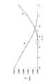
- FIG. 9is a diagram showing the powers of the totally reflected rays and the refracted rays with respect to the taper value.
- FIG. 10Ais a diagram showing transmitted rays, refracted rays, and total reflected rays when the central thickness of the lens body of the phakic intraocular lens according to the second embodiment is 0.53 mm.
- FIG. 10Ais a diagram showing transmitted rays, refracted rays, and total reflected rays when the central thickness of the lens body of the phakic intraocular lens according to the second embodiment is 0.53 mm.
- FIG. 10Bis a diagram showing transmitted rays, refracted rays, and total reflected rays when the central thickness of the lens body is 0.25 mm.
- FIG. 11is a diagram showing stray light intensity of refracted rays and total reflected rays with respect to the center thickness of the lens body of the phakic intraocular lens according to the second embodiment.
- FIG. 12Ais a diagram showing a hole in the lens body of the phakic intraocular lens according to the third embodiment, which is tapered and has a light absorbing film coated on the inner peripheral surface.
- FIG. 12Bis a diagram showing how stray light is absorbed by the light absorbing film applied to the holes shown in FIG. 12A.
- FIG. 13Ais a diagram showing a hole in the lens body of the phakic intraocular lens according to the fourth embodiment, which is tapered and has a light diffusing film formed on the inner peripheral surface.
- FIG. 13Bis a diagram showing how stray light is diffused by processing the light diffusing film formed in the holes shown in FIG. 13A or a fine uneven surface.
- FIG. 1is a diagram showing a configuration of a phakic intraocular lens according to a first embodiment of the present invention.
- the phakic intraocular lens 1 according to Example 1 of the present inventionis made of collagen copolymer material, Collamer, and is implanted between the iris and the crystalline lens.
- the phakic intraocular lens 1includes a lens body 5 arranged at the center and a support portion 3 arranged outside the lens body 5 and supporting the lens body 5.
- 4a and 4bare markings of the phakic intraocular lens and are provided on the outside of the lens body 5.
- One small circular hole 6is formed in the center of the lens body 5.
- FIG. 2is a cross-sectional side view of an eye having a phakic intraocular lens according to the first embodiment of the present invention.
- the eye 8has a cornea 9, a crystalline lens 10, an iris 11, anterior chamber 13, and posterior chamber 14.
- the phakic intraocular lens 1is implanted between the iris 11 and the crystalline lens 10.
- a gap 12is provided between the phakic intraocular lens 1 and the crystalline lens 10.
- the aqueous humor in the posterior chamber 14flows through the gap 12 and the hole 6 in the lens body 5 to the anterior chamber 13.
- FIG. 3is a diagram showing transmitted rays, refracted rays, and total reflected rays when the incident light is incident on the hole 6 of the lens body 5 from the anterior chamber 13.
- the lens body 5is composed of a concave lens, and the incident light to the hole 6 is totally reflected by the transmitted ray 21 that passes through the hole 6 as it is, the refracted ray 22 that is refracted by the hole 6, and the hole 6. It is divided into the total reflected light beam 23.
- the refracted ray 22 and the reflected ray 23are stray light.
- the refractive index n0 of the cornea 9is, for example, 1.376.
- the refractive index n1 of the aqueous humoris, for example, 1.337.
- the refractive index n2 of the lens body 5is, for example, 1.46.
- the refractive index n3 of the crystalline lens 10is, for example, 1.336.
- the off-axisis, for example, 3 °, and the number of rays is, for example, 5,000,000.
- the refracted ray 22 and the reflected ray 23 shown in FIG. 3can be understood by the explanation of the refracted ray shown in FIG. 4A and the explanation of the reflected ray shown in FIG. 4B.
- the bunch of water having a refractive index n1 and the lens body 5 having a refractive index n2come into contact with each other, and the incident light is transferred from the bunch of water having a refractive index n1 to the hole 6 of the lens body 5 having a refractive index n2. It is incident on the upper surface 6A.
- the refractive index n2 of the lens body 5is larger than the refractive index n1 of the bunch of water, the emission angle ⁇ t is smaller than the incident angle ⁇ i, and the refracted ray 22 is refracted.
- the incident lightis incident on the lower surface 6B of the hole 6 of the lens body 5 having the refractive index n2 from the aqueous humor having the refractive index n1.
- the refractive index n2 of the lens body 5is larger than the refractive index n1 of the bunch of water, the incident light is reflected by the lower surface 6B of the hole 6, and the reflected light beam 23 emits substantially the same as the incident angle ⁇ i. It emits at an angle ⁇ r.
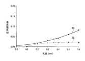
- FIG. 5is a diagram showing the stray light intensity of the refracted light ray and the stray light intensity of the total reflected light ray with respect to the pore diameter.
- the radiant poweris, for example, 1 W.
- the stray light intensity of the refracted ray 22 and the stray light intensity of the total reflected ray 23increase.
- the stray light intensity of the total internal reflection rayis larger than the stray light intensity of the refracted ray.
- the hole diameteris, for example, 0.1 mm to 1.0 mm.
- the stray light intensityis 0.01%.
- the stray light intensityis 0.04%. Therefore, the diameter of the hole 6 is preferably 0.1 mm to 0.2 mm.
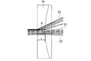
- FIG. 6Ais a diagram showing holes formed in a tapered shape so that the hole diameter on the incident side of the phakic intraocular lens according to the first embodiment is larger than the hole diameter on the exit side.
- the hole 60 of the lens body 5 shown in FIG. 6Ais formed in a tapered shape so that the hole diameter d1 on the incident side of the incident light is larger than the hole diameter d2 on the exit side.
- This tapermay be linearly inclined, may be a curved line such as a parabola, or may be inclined in an arbitrary shape.
- the ratio of the hole diameter d2 to the hole diameter d1, that is, (d2 / d1)is defined as the taper ratio.
- FIG. 6Bis a diagram showing a transmitted ray 21, a refracted ray 22, and a total reflected ray 23 in a hole having a taper ratio of 1.0.
- the incident lightis refracted and reflected near the entrance of the hole 6 to become a refracted ray 22 and a total reflected ray 23. Therefore, the total number of totally reflected light rays 23 increases within a predetermined range.
- FIG. 7Ashows the spots on the retinal surface of the transmitted ray 21 and the total reflected ray 23 of the hole 6 having a taper ratio of 1.0.
- the X directionis -1 mm to 1 mm and the Y direction is -1 mm to 1 mm.
- the X direction and the Y directionare set in the incident surface of the lens body 5, and the thickness direction of the hole 60, that is, the direction in which the transmitted light ray 21 travels is set in the Z direction.
- the totally reflected light beam 23appears in a circle within a predetermined range.
- the incident lightis refracted from substantially the center of the hole 60 in the thickness direction to the exit side in the upper surface taper 60a of the hole 60. Since the refracting rays 22 are used, the number of refracting rays 22 is smaller than that of the refracting rays 22 of the hole 6 having a taper ratio of 1.0.
- the incident lightis totally reflected at the lower surface taper 60b of the hole 60 while changing the angle due to the inclination of the lower surface taper 60b as it goes from the incident end to the exit end of the hole 60. Therefore, the reflected light rays 23 are dispersed in the radial direction, and as shown in FIG. 7B, the spots due to the total reflected light rays are within a predetermined range (for example, -1 mm to 1 mm in the X direction and -1 mm to 1 mm in the Y direction). It disappears completely, and only a few small spots appear even outside the specified range. That is, by setting the taper ratio of the holes 60 to 0.85, stray light can be significantly reduced.
- a predetermined rangefor example, -1 mm to 1 mm in the X direction and -1 mm to 1 mm in the Y direction. It disappears completely, and only a few small spots appear even outside the specified range. That is, by setting the taper ratio of the holes 60 to 0.85,
- FIG. 8Ais a diagram showing a hole 61 formed in a tapered shape so that the hole diameter d1 on the incident side of the phakic intraocular lens according to the first embodiment is smaller than the hole diameter d2 on the exit side.
- FIG. 8Bis a diagram showing a refracted ray and a totally reflected ray in a hole having a taper ratio of, for example, 1.2.
- FIG. 8Cis a diagram showing a refracted ray 22 and a total reflected ray 23 in a hole having a taper ratio of 1.2.
- the upper surface taper 61a and the lower surface taper 61b of the hole 61spread from the incident end to the emitted end, so that the incident light is substantially near the center in the thickness direction of the hole 61.
- the total reflectionis caused by the inclination of the tapers 61a and 61b. Therefore, the dispersion of the total reflected light rays 23 in the radial direction becomes small.
- the spot due to the total reflection ray 23does not appear within the predetermined range, but a large circular spot due to the total reflection ray 23 appears outside the predetermined range. Therefore, it is inappropriate to set the taper ratio to 1.2.
- FIG. 9is a diagram showing the powers of the totally reflected light rays 23 and the refracted rays 22 with respect to the taper value. From FIG. 9, the taper ratio in which the total reflection ray 23 is not generated and the refracted ray 22 is smaller, that is, the optimum taper ratio is 0.85. Even if the taper ratio is 0.8 to 0.9, almost no total reflected light rays are generated, so the taper ratio may be set in this range.
- the hole 60is formed in a tapered shape so that the hole diameter d1 on the incident side of the lens body 5 is larger than the hole diameter d2 on the exit side.
- the taper ratio of the holes 60is not limited to 0.85, and even if the taper ratio is 0.8 to 0.9, stray light can be significantly reduced.
- FIG. 10Ais a diagram showing a transmitted ray 21, a refracted ray 22, and a total reflected ray 23 when the center thickness t of the lens body 5 of the phakic intraocular lens according to the second embodiment is, for example, 0.53 mm.
- FIG. 10Bis a diagram showing a transmitted ray 21, a refracted ray 22, and a total reflected ray 23 when the central thickness of the lens body is, for example, 0.25 mm.
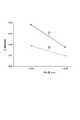
- FIG. 11is a diagram showing the stray light intensity of the refracted ray 22 and the total reflected ray 23 with respect to the center thickness of the lens body 5 of the phakic intraocular lens according to the second embodiment.
- the stray light intensity at which the center thickness of the lens body 5 is 0.25 mmis smaller than the stray light intensity at which the center thickness is 0.53 mm.
- the stray light intensity of the refracted ray 22is about 0.01%
- the stray light intensity of the total reflected ray 23is about 0.018%.
- the taper ratio of the holesis set to, for example, 0.85 and the center thickness of the lens body 5 is set to, for example, 0.2 mm, the stray light intensity is further reduced. Therefore, it is preferable to set the taper ratio of the holes to 0.85 and set the center thickness of the lens body 5 to 0.2 to 0.3 mm.
- the taper ratio of the holesis set to, for example, 0.85 and the hole diameter of the lens body 5 is set to, for example, 0.2 mm, the stray light intensity is further reduced. Therefore, it is preferable to set the taper ratio of the holes to 0.85 and set the hole diameter of the lens body 5 to 0.1 to 0.2 mm.
- the phakic intraocular lens according to the third embodiment shown in FIG. 12Ais different from the phakic intraocular lens according to the first embodiment shown in FIG. 6A in that a light absorbing film 71 is added. The details will be described below.
- the holes 62are formed in a tapered shape so that the hole diameter d1 on the incident side of the incident light is larger than the hole diameter d2 on the exit side.
- the taper ratio of the holes 62is, for example, 0.85.
- a light absorbing film 71is coated on the inner peripheral surfaces of the upper surface taper 61a and the lower surface taper 61b.
- black fine particles or a black dyeare mixed in the light absorption film 71.
- black fine particles or a black dyeare mixed in the light absorption film 71.
- aniline black, cyanine black, carbon, titanium black, black iron oxide, chromium oxide, manganese oxide and the likeare mixed with the resin.
- the taper ratio of the holes 62is set to 0.85, and the light absorbing film 71 is coated on the inner peripheral surfaces of the upper surface taper 61a and the lower surface taper 61b.
- the 71can absorb the refracted rays 22 and the totally reflected rays 23 generated by the upper surface taper 61a and the lower surface taper 61b. Therefore, the stray light generated by the hole 62 can be further reduced.
- FIG. 13Ais different from the phakic intraocular lens according to the fourth embodiment in that a light diffusing film 72 is added to the phakic intraocular lens according to the first embodiment shown in FIG. 6A. The details will be described below.
- the holes 63are formed in a tapered shape so that the hole diameter d1 on the incident side of the incident light is larger than the hole diameter d2 on the exit side.
- the taper ratio of the hole 63is, for example, 0.85.
- a light diffusing film 72is coated on the inner peripheral surfaces of the upper surface taper 61a and the lower surface taper 61b.
- Examples of the light diffusion film 72include white inorganic particles such as titanium dioxide, zinc sulfide, zinc oxide, alumina, magnesium oxide, calcium carbonate and barium sulfate, and white organic particles such as fluorine particles.
- the taper ratio of the holes 63is set to 0.85, and the light diffusing film 72 is applied to the inner peripheral surfaces of the upper surface taper 61a and the lower surface taper 61b.
- the 72can diffuse the refracted rays 22 and the totally reflected rays 23 generated by the upper surface taper 61a and the lower surface taper 61b. Therefore, the stray light generated by the hole 63 can be further reduced.
- the present inventionis not limited to the phakic intraocular lens according to the first to fourth embodiments.
- the phakic intraocular lens according to the first to fourth embodimentsonly the inner peripheral surface of the hole is tapered, but the edge portion of the hole may also be tapered.
- a holeis provided in the center of the lens body 5, but the hole is not limited to this, and a hole other than the center of the lens body 5 is provided. May be provided.
- the present inventionis applicable to an intraocular lens implanted between the iris and the crystalline lens.
Landscapes
- Health & Medical Sciences (AREA)
- Ophthalmology & Optometry (AREA)
- Cardiology (AREA)
- Oral & Maxillofacial Surgery (AREA)
- Transplantation (AREA)
- Engineering & Computer Science (AREA)
- Biomedical Technology (AREA)
- Heart & Thoracic Surgery (AREA)
- Vascular Medicine (AREA)
- Life Sciences & Earth Sciences (AREA)
- Animal Behavior & Ethology (AREA)
- General Health & Medical Sciences (AREA)
- Public Health (AREA)
- Veterinary Medicine (AREA)
- Prostheses (AREA)
Abstract
Description
Translated fromJapanese本発明は、有水晶体眼内レンズに関する。The present invention relates to a phakic intraocular lens.
有水晶体眼内レンズは、眼鏡やコンタクトレンズ以外の視覚の疾患を補正する一つの手段として認識されている。この有水晶体眼内レンズとしては、虹彩と水晶体との間に移植されるレンズが知られている(特許文献1~4)。The phakic intraocular lens is recognized as a means of correcting visual disorders other than spectacles and contact lenses. As this phakic intraocular lens, a lens implanted between the iris and the crystalline lens is known (
有水晶体眼内レンズは、平らな縁を有し、ある条件下では、網膜上に入射光を屈折、反射、散乱させ、ハロー、リング又は円弧のような望ましくはない光学像(迷光)を作る。物理的に形成されるこの光像は、不快感や物の見えづらさを伴うまぶしさの主観的な感覚であるグレアの原因となる。このグレアは、眼内レンズの露出された縁で屈折、反射し又は散乱したとき、この光線により生じる。特許文献1-3には、グレアを低減する眼内レンズが開示されている。A phakic intraocular lens has a flat edge that, under certain conditions, refracts, reflects, and scatters incident light on the retina, creating an unwanted optical image (stray light) such as a halo, ring, or arc. .. This physically formed light image causes glare, a subjective sensation of glare with discomfort and obscurity. This glare is caused by this ray when it is refracted, reflected or scattered at the exposed edge of the intraocular lens. Patent Document 1-3 discloses an intraocular lens that reduces glare.
特許文献4に記載された有水晶体眼内レンズは、虹彩と水晶体との間に移植され、レンズ中央部に配置された回折格子に同心円状に溝を形成し、回折格子の外側に配置された支持部が回折格子を支持し、回折格子の中心に孔を形成している。The crystalline intraocular lens described in
しかしながら、特許文献4に記載された有水晶体眼内レンズや現行の眼内レンズでは、レンズの中心に孔が形成されているため、入射光が孔を通ってそのまま透過光線として網膜に出力される。また、一部の入射光は、孔で反射や屈折されて迷光が発生する。このため、ハロー、グレアが発生する。However, in the phakic intraocular lens described in
本発明は、孔により発生する迷光を低減することができる有水晶体眼内レンズを提供することを目的とする。An object of the present invention is to provide a phakic intraocular lens capable of reducing stray light generated by a hole.
上記の課題を解決するために、本発明に係る有水晶体眼内レンズは、虹彩と水晶体との間に移植される有水晶体眼内レンズであって、中央部に配置され、孔が形成されたレンズ本体と、前記レンズ本体の外側に配置され前記レンズ本体を支持する支持部とを備え、前記孔は、入射光が入射される入射側の孔径が出射側の孔径よりも大きくなるようにテーパ状に形成されている。In order to solve the above problems, the phakic intraocular lens according to the present invention is a phakic intraocular lens implanted between the iris and the crystalline lens, and is arranged in the central portion to form a hole. A lens body and a support portion arranged outside the lens body to support the lens body are provided, and the hole is tapered so that the hole diameter on the incident side where the incident light is incident is larger than the hole diameter on the exit side. It is formed in a shape.
以下、本発明のいくつかの実施形態に係る有水晶体眼内レンズを、図面を参照しながら詳細に説明する。Hereinafter, the phakic intraocular lens according to some embodiments of the present invention will be described in detail with reference to the drawings.
(第1の実施形態)
図1は本発明の第1の実施形態に係る有水晶体眼内レンズの構成を示す図である。本発明の実施例1に係る有水晶体眼内レンズ1は、コラーゲンの共重合体素材、コラマー(Collamer)からなり、虹彩と水晶体との間に移植される。有水晶体眼内レンズ1は、中央部に配置されたレンズ本体5と、レンズ本体5の外側に配置され且つレンズ本体5を支持する支持部3とを備えている。(First Embodiment)
FIG. 1 is a diagram showing a configuration of a phakic intraocular lens according to a first embodiment of the present invention. The phakic
4a,4bは、有水晶体眼内レンズのマーキングであり、レンズ本体5の外側に設けられている。レンズ本体5の中心には1つの円状の小さい孔6が形成されている。4a and 4b are markings of the phakic intraocular lens and are provided on the outside of the
図2は本発明の実施例1に係る有水晶体眼内レンズを有する眼の断面側面図である。図2に示すように、眼8は、角膜9、水晶体10、虹彩11、前房13、後房14を有している。有水晶体眼内レンズ1は、虹彩11と水晶体10との間に移植される。有水晶体眼内レンズ1と水晶体10との間には、ギャップ12が設けられている。後房14に有する房水は、ギャップ12とレンズ本体5の孔6とを通り前房13に流れる。FIG. 2 is a cross-sectional side view of an eye having a phakic intraocular lens according to the first embodiment of the present invention. As shown in FIG. 2, the
図3は入射光が前房13からレンズ本体5の孔6に入射されたときの透過光線と屈折光線と全反射光線を示す図である。レンズ本体5は、図3に示すように凹レンズからなり、孔6への入射光は、孔6をそのまま透過する透過光線21と、孔6で屈折される屈折光線22と、孔6で全反射する全反射光線23とに分かれる。屈折光線22と反射光線23とが迷光である。FIG. 3 is a diagram showing transmitted rays, refracted rays, and total reflected rays when the incident light is incident on the
ここで、角膜9の屈折率n0は、例えば1.376である。房水の屈折率n1は、例えば1.337である。レンズ本体5の屈折率n2は、例えば1.46である。水晶体10の屈折率n3は、例えば1.336である。軸外は例えば、3°であり、光線本数は、例えば5,000,000である。Here, the refractive index n0 of the
図3に示す屈折光線22と反射光線23は、図4Aに示す屈折光線の説明と図4Bに示す反射光線の説明によって理解できる。The refracted
図3及び図4Aに示すように、屈折率n1の房水と屈折率n2のレンズ本体5とが接触し、入射光が屈折率n1の房水から屈折率n2のレンズ本体5の孔6の上面6Aに入射する。このとき、レンズ本体5の屈折率n2の方が房水の屈折率n1よりも大きいため、入射角度θiより出射角度θtが小さくなって屈折光線22は屈折する。As shown in FIGS. 3 and 4A, the bunch of water having a refractive index n1 and the
また、図3及び図4Bに示すように、入射光が屈折率n1の房水から屈折率n2のレンズ本体5の孔6の下面6Bに入射する。このとき、レンズ本体5の屈折率n2の方が房水の屈折率n1よりも大きいため、入射光は、孔6の下面6Bで反射して、反射光線23は、入射角度θiとほぼ同じ出射角度θrで出射する。Further, as shown in FIGS. 3 and 4B, the incident light is incident on the
図5は、孔径に対する屈折光線の迷光強度と全反射光線の迷光強度を示す図である。ここで、放射パワーは例えば1Wである。FIG. 5 is a diagram showing the stray light intensity of the refracted light ray and the stray light intensity of the total reflected light ray with respect to the pore diameter. Here, the radiant power is, for example, 1 W.
図5に示すように、孔6の孔径(直径)が大きくなるほど、屈折光線22の迷光強度と全反射光線23の迷光強度とが大きくなる。特に、屈折光線の迷光強度よりも全反射光線の迷光強度の方が大きいことがわかる。As shown in FIG. 5, as the hole diameter (diameter) of the
孔径は、例えば、0.1mm~1.0mmである。孔径が0.1mmである場合、迷光強度は、0.01%である。孔径が0.36mmである場合、迷光強度は、0.04%である。このため、孔6の直径は、0.1mm~0.2mmであることが好ましい。The hole diameter is, for example, 0.1 mm to 1.0 mm. When the pore diameter is 0.1 mm, the stray light intensity is 0.01%. When the pore diameter is 0.36 mm, the stray light intensity is 0.04%. Therefore, the diameter of the
(第1の実施形態の迷光対策)
図6Aは第1の実施形態に係る有水晶体眼内レンズの入射側の孔径が出射側の孔径よりも大きくなるようにテーパ状に形成された孔を示す図である。図6Aに示すレンズ本体5の孔60は、入射光の入射側の孔径d1が出射側の孔径d2よりも大きくなるようにテーパ状に形成されている。このテーパは、直線的に傾斜するものであっても良く、放物線等の曲線、あるいは任意形状で傾斜したものでもよい。孔径d1に対する孔径d2の比、即ち、(d2/d1)をテーパ比と定義する。(Countermeasures against stray light in the first embodiment)
FIG. 6A is a diagram showing holes formed in a tapered shape so that the hole diameter on the incident side of the phakic intraocular lens according to the first embodiment is larger than the hole diameter on the exit side. The
図6Bはテーパ比が1.0の孔での透過光線21と屈折光線22と全反射光線23を示す図である。テーパ比が1.0の孔6の場合、入射光は、孔6の入口付近で屈折及び反射して屈折光線22と全反射光線23となる。このため、全反射光線23が所定範囲内で多くなる。FIG. 6B is a diagram showing a transmitted
図7Aにテーパ比が1.0の孔6の透過光線21と全反射光線23の網膜面におけるスポットを示す。所定の範囲内は、図7Aに示すように、例えば、X方向が-1mm~1mm,Y方向が-1mm~1mmである。ここで、X方向及びY方向はレンズ本体5の入射面内に設定され、孔60の厚み方向、即ち透過光線21が進む方向がZ方向に設定される。図7Aに示すように、所定範囲内に全反射光線23が円状に現れる。FIG. 7A shows the spots on the retinal surface of the transmitted
これに対して、図6Cに示すテーパ比が例えば0.85の孔60の場合、入射光は、孔60の上面テーパ60aにおいて、孔60の厚み方向の略中央付近から出射側まで屈折して屈折光線22となるため、テーパ比が1.0の孔6の屈折光線22よりも屈折光線22が少なくなる。On the other hand, in the case of the
また、入射光は、孔60の下面テーパ60bにおいて、孔60の入射端から出射端に行くに従って、下面テーパ60bの傾斜により角度を変えながら全反射していく。このため、反射光線23が半径方向に分散していき、図7Bに示すように、全反射光線によるスポットが所定の範囲内(例えばX方向-1mm~1mm,Y方向-1mm~1mm)には完全になくなり、所定の範囲外でも点状の小さいスポットがわずかに現れるのみである。即ち、孔60のテーパ比を0.85にすることで、迷光を大幅に低減することができる。Further, the incident light is totally reflected at the
図8Aは第1の実施形態に係る有水晶体眼内レンズの入射側の孔径d1が出射側の孔径d2よりも小さくなるようにテーパ状に形成された孔61を示す図である。図8Bはテーパ比が例えば1.2の孔での屈折光線と全反射光線を示す図である。図8Cはテーパ比が1.2の孔での屈折光線22と全反射光線23を示す図である。FIG. 8A is a diagram showing a
テーパ比が1.2の孔61の場合、孔61の上面テーパ61aと下面テーパ61bは、入射端から出射端に行くに従って広がっているため、入射光は、孔61の厚み方向の略中央付近からテーパ61a,61bの傾斜により全反射していく。このため、全反射光線23の半径方向への分散が小さくなる。In the case of the
この場合には、図8Cに示すように、全反射光線によるスポットが所定の範囲内では現れないが、所定の範囲外で全反射光線23による円状の大きなスポットが現れる。このため、テーパ比を1.2に設定することは、不適切である。In this case, as shown in FIG. 8C, the spot due to the
図9はテーパの値に対する全反射光線23と屈折光線22のパワーを示す図である。図9から全反射光線23が発生せず且つ屈折光線22がより小さいテーパ比、即ち最適なテーパ比は、0.85である。なお、テーパ比は、0.8~0.9でも全反射光線がほとんど発生しないので、この範囲に設定してもよい。FIG. 9 is a diagram showing the powers of the totally reflected
このように第1の実施形態に係る有水晶体眼内レンズ1によれば、レンズ本体5の入射側の孔径d1が出射側の孔径d2よりも大きくなるようにテーパ状に孔60を形成し、孔60のテーパ比を0.85にすることで、迷光を大幅に低減することができる。また、孔60のテーパ比は、0.85に限定されず、テーパ比は、0.8~0.9であっても迷光を大幅に低減することができる。As described above, according to the phakic
(第2の実施形態)
図10Aは第2の実施形態に係る有水晶体眼内レンズのレンズ本体5の中心厚tが例えば0.53mmの場合の透過光線21と屈折光線22と全反射光線23を示す図である。図10Bはレンズ本体の中心厚が例えば0.25mmの場合の透過光線21と屈折光線22と全反射光線23を示す図である。図11は第2の実施形態に係る有水晶体眼内レンズのレンズ本体5の中心厚に対する屈折光線22と全反射光線23の迷光強度を示す図である。(Second Embodiment)
FIG. 10A is a diagram showing a transmitted
図11に示すように、レンズ本体5の中心厚が0.25mmの迷光強度は、中心厚が0.53mmの迷光強度よりも小さいことがわかる。中心厚が0.25mmの場合、屈折光線22の迷光強度が約0.01%であり、全反射光線23の迷光強度が約0.018%である。As shown in FIG. 11, it can be seen that the stray light intensity at which the center thickness of the
また、孔のテーパ比を例えば0.85に設定し、レンズ本体5の中心厚が例えば0.2mmにした場合には迷光強度がさらに小さくなる。このため、孔のテーパ比を0.85に設定し、レンズ本体5の中心厚を0.2~0.3mmにするのが良い。Further, when the taper ratio of the holes is set to, for example, 0.85 and the center thickness of the
また、孔のテーパ比を例えば0.85に設定し、レンズ本体5の孔径を例えば0.2mmにした場合には、迷光強度がさらに小さくなる。このため、孔のテーパ比を0.85に設定し、レンズ本体5の孔径を0.1~0.2mmにするのが良い。Further, when the taper ratio of the holes is set to, for example, 0.85 and the hole diameter of the
(第3の実施形態)
図12Aに示す第3の実施形態に係る有水晶体眼内レンズは、図6Aに示す第1の実施形態に係る有水晶体眼内レンズに対して、光吸収膜71を追加した点が異なる。以下にその詳細を説明する。(Third Embodiment)
The phakic intraocular lens according to the third embodiment shown in FIG. 12A is different from the phakic intraocular lens according to the first embodiment shown in FIG. 6A in that a
図12Aに示すレンズ本体5において、孔62は、入射光の入射側の孔径d1が出射側の孔径d2よりも大きくなるようにテーパ状に形成されている。この場合、孔62のテーパ比は例えば0.85である。上面テーパ61aと下面テーパ61bには内周面に光吸収膜71が塗布されている。In the
光吸収膜71には、例えば、黒色微粒子または黒色の染料を混合されている。例えば、アニリンブラック、シアニンブラック、炭素、チタンブラック、黒色酸化鉄、酸化クロム、または酸化マンガン等が樹脂に混合される。For example, black fine particles or a black dye are mixed in the
このように孔62のテーパ比を0.85に設定し、上面テーパ61aと下面テーパ61bには内周面に光吸収膜71が塗布されているので、図11Bに示すように、光吸収膜71により上面テーパ61aと下面テーパ61bで発生する屈折光線22と全反射光線23とを吸収することができる。従って、孔62により発生する迷光をさらに、低減することができる。In this way, the taper ratio of the
(第4の実施形態)
図13Aは第4の実施形態に係る有水晶体眼内レンズは、図6Aに示す第1の実施形態に係る有水晶体眼内レンズに対して、光拡散膜72を追加した点が異なる。以下にその詳細を説明する。(Fourth Embodiment)
FIG. 13A is different from the phakic intraocular lens according to the fourth embodiment in that a
図13Aに示すレンズ本体5において、孔63は、入射光の入射側の孔径d1が出射側の孔径d2よりも大きくなるようにテーパ状に形成されている。この場合、孔63のテーパ比は例えば0.85である。上面テーパ61aと下面テーパ61bには内周面に光拡散膜72が塗布されている。In the
光拡散膜72には、例えば、二酸化チタン、硫化亜鉛、酸化亜鉛、アルミナ、酸化マグネシウム、炭酸カルシウム、硫酸バリウム等の白色無機粒子やフッ素粒子等の白色有機粒子が挙げられる。Examples of the
このように孔63のテーパ比を0.85に設定し、上面テーパ61aと下面テーパ61bには内周面に光拡散膜72が塗布されているので、図13Bに示すように、光拡散膜72により上面テーパ61aと下面テーパ61bで発生する屈折光線22と全反射光線23とを拡散することができる。従って、孔63により発生する迷光をさらに、低減することができる。In this way, the taper ratio of the
また、光拡散膜72の代わりに、内周面に対して微細な凹凸面への加工を施しても、光拡散膜72の効果と同様の効果を得ることができる。Further, even if the inner peripheral surface is processed into a fine uneven surface instead of the
なお、本発明は、第1の実施形態乃至第4の実施形態に係る有水晶体眼内レンズに限定されるものではない。第1の実施形態乃至第4の実施形態に係る有水晶体眼内レンズでは、孔の内周面のみをテーパ状としたが、孔のエッジ部分もテーパ状にしても良い。The present invention is not limited to the phakic intraocular lens according to the first to fourth embodiments. In the phakic intraocular lens according to the first to fourth embodiments, only the inner peripheral surface of the hole is tapered, but the edge portion of the hole may also be tapered.
また、第1の実施形態乃至第4の実施形態に係る有水晶体眼内レンズでは、レンズ本体5の中心に孔を設けたが、これに限定されることなく、レンズ本体5の中心以外に孔を設けてもよい。Further, in the phakic intraocular lens according to the first to fourth embodiments, a hole is provided in the center of the
本発明は、虹彩と水晶体との間に移植される眼内レンズに適用可能である。The present invention is applicable to an intraocular lens implanted between the iris and the crystalline lens.
Claims (6)
Translated fromJapanese中央部に配置され、孔が形成されたレンズ本体と、
前記レンズ本体の外側に配置され前記レンズ本体を支持する支持部とを備え、
前記孔は、入射光が入射される入射側の孔径が出射側の孔径よりも大きくなるようにテーパ状に形成されている有水晶体眼内レンズ。A phakic intraocular lens that is implanted between the iris and the crystalline lens.
The lens body, which is located in the center and has holes,
It is provided with a support portion that is arranged on the outside of the lens body and supports the lens body.
The hole is a phakic intraocular lens formed in a tapered shape so that the hole diameter on the incident side where the incident light is incident is larger than the hole diameter on the exit side.
Priority Applications (3)
| Application Number | Priority Date | Filing Date | Title |
|---|---|---|---|
| PCT/JP2020/003617WO2021152815A1 (en) | 2020-01-31 | 2020-01-31 | Phakic intraocular lens |
| JP2021523528AJP7088589B2 (en) | 2020-01-31 | 2021-01-20 | Phakic intraocular lens |
| PCT/JP2021/001888WO2021153381A1 (en) | 2020-01-31 | 2021-01-20 | Phakic intraocular lens |
Applications Claiming Priority (1)
| Application Number | Priority Date | Filing Date | Title |
|---|---|---|---|
| PCT/JP2020/003617WO2021152815A1 (en) | 2020-01-31 | 2020-01-31 | Phakic intraocular lens |
Publications (1)
| Publication Number | Publication Date |
|---|---|
| WO2021152815A1true WO2021152815A1 (en) | 2021-08-05 |
Family
ID=77078128
Family Applications (2)
| Application Number | Title | Priority Date | Filing Date |
|---|---|---|---|
| PCT/JP2020/003617CeasedWO2021152815A1 (en) | 2020-01-31 | 2020-01-31 | Phakic intraocular lens |
| PCT/JP2021/001888CeasedWO2021153381A1 (en) | 2020-01-31 | 2021-01-20 | Phakic intraocular lens |
Family Applications After (1)
| Application Number | Title | Priority Date | Filing Date |
|---|---|---|---|
| PCT/JP2021/001888CeasedWO2021153381A1 (en) | 2020-01-31 | 2021-01-20 | Phakic intraocular lens |
Country Status (2)
| Country | Link |
|---|---|
| JP (1) | JP7088589B2 (en) |
| WO (2) | WO2021152815A1 (en) |
Citations (3)
| Publication number | Priority date | Publication date | Assignee | Title |
|---|---|---|---|---|
| US20050149184A1 (en)* | 2003-12-15 | 2005-07-07 | Theo Bogaert | Phakic intraocular lens with improved fluid circulation properties |
| JP2010525884A (en)* | 2007-04-30 | 2010-07-29 | アルコン,インコーポレイティド | Intraocular lens with peripheral area designed to reduce negative abnormal optical vision |
| US20160067035A1 (en)* | 2014-09-09 | 2016-03-10 | Staar Surgical Company | Intraocular Lens With Central Hole For Improved Fluid Flow And Minimized Light Scattering |
Family Cites Families (3)
| Publication number | Priority date | Publication date | Assignee | Title |
|---|---|---|---|---|
| JPS62210440A (en)* | 1986-03-12 | 1987-09-16 | Dainippon Printing Co Ltd | Lens sheet for transmissive projection screen |
| CA2770735C (en)* | 2009-08-13 | 2017-07-18 | Acufocus, Inc. | Masked intraocular implants and lenses |
| EP3173050B1 (en)* | 2014-07-25 | 2020-02-19 | Musashino Lens Research, Inc. | Phakic intraocular lens |
- 2020
- 2020-01-31WOPCT/JP2020/003617patent/WO2021152815A1/ennot_activeCeased
- 2021
- 2021-01-20WOPCT/JP2021/001888patent/WO2021153381A1/ennot_activeCeased
- 2021-01-20JPJP2021523528Apatent/JP7088589B2/enactiveActive
Patent Citations (3)
| Publication number | Priority date | Publication date | Assignee | Title |
|---|---|---|---|---|
| US20050149184A1 (en)* | 2003-12-15 | 2005-07-07 | Theo Bogaert | Phakic intraocular lens with improved fluid circulation properties |
| JP2010525884A (en)* | 2007-04-30 | 2010-07-29 | アルコン,インコーポレイティド | Intraocular lens with peripheral area designed to reduce negative abnormal optical vision |
| US20160067035A1 (en)* | 2014-09-09 | 2016-03-10 | Staar Surgical Company | Intraocular Lens With Central Hole For Improved Fluid Flow And Minimized Light Scattering |
Also Published As
| Publication number | Publication date |
|---|---|
| JPWO2021153381A1 (en) | 2021-08-05 |
| JP7088589B2 (en) | 2022-06-21 |
| WO2021153381A1 (en) | 2021-08-05 |
Similar Documents
| Publication | Publication Date | Title |
|---|---|---|
| RU2009144093A (en) | Intraocular lens with a peripheral area, designed to reduce negative dysfotopsia | |
| US7252683B2 (en) | Intraocular lens for inhibiting cell growth and reducing glare | |
| JP5290253B2 (en) | IOL suppresses cell growth and reduces flicker | |
| EP2152202B1 (en) | Iol peripheral surface designs to reduce negative dysphotopsia | |
| US20080269885A1 (en) | IOL Peripheral Surface Designs to Reduce Negative Dysphotopsia | |
| US20080269884A1 (en) | Graduated blue filtering intraocular lens | |
| JP2007535783A (en) | Optical device with stepped lens | |
| JP6589675B2 (en) | Light source unit | |
| JP2005235744A (en) | Fresnel lens spotlight for joining and changing spacing of optical element | |
| US11567348B2 (en) | Tear shaping for refractive correction | |
| JP4482728B2 (en) | Light diffusing element | |
| WO2021152815A1 (en) | Phakic intraocular lens | |
| US20190307555A1 (en) | Hybrid optical edge for an intraocular lens (iol) | |
| JP2015118818A (en) | Lighting appliance | |
| JP7541882B2 (en) | Eyeglass lenses and their design method | |
| CN223183925U (en) | Lens assembly and light feeding equipment | |
| CN120215141A (en) | Implantable contact lenses | |
| KR20250126129A (en) | Ophthalmic lenses with a transition light scattering center for myopia management | |
| CN120178531A (en) | Optical lenses | |
| CN115542577A (en) | Vision Control Lenses & Glasses | |
| EP0433834A1 (en) | Contact glass for transsclerotic/transchoroidal ophthalmotherapy with lightbeams, particularly laserbeams | |
| JPH03136633A (en) | Ophthalmic lighting device | |
| CN119084863A (en) | A soft light lens and its production process | |
| CN118938512A (en) | Myopia prevention and control lens | |
| TWM557336U (en) | Lamp module |
Legal Events
| Date | Code | Title | Description |
|---|---|---|---|
| 121 | Ep: the epo has been informed by wipo that ep was designated in this application | Ref document number:20917040 Country of ref document:EP Kind code of ref document:A1 | |
| NENP | Non-entry into the national phase | Ref country code:DE | |
| 32PN | Ep: public notification in the ep bulletin as address of the adressee cannot be established | Free format text:NOTING OF LOSS OF RIGHTS PURSUANT TO RULE 112(1) EPC (EPO FORM 1205A DATED 19/10/2022) | |
| NENP | Non-entry into the national phase | Ref country code:JP | |
| 122 | Ep: pct application non-entry in european phase | Ref document number:20917040 Country of ref document:EP Kind code of ref document:A1 |