WO2021152752A1 - Treatment system and control parameter calculation method - Google Patents
Treatment system and control parameter calculation methodDownload PDFInfo
- Publication number
- WO2021152752A1 WO2021152752A1PCT/JP2020/003279JP2020003279WWO2021152752A1WO 2021152752 A1WO2021152752 A1WO 2021152752A1JP 2020003279 WJP2020003279 WJP 2020003279WWO 2021152752 A1WO2021152752 A1WO 2021152752A1
- Authority
- WO
- WIPO (PCT)
- Prior art keywords
- treatment
- completion time
- inspection
- intensity
- processor
- Prior art date
- Legal status (The legal status is an assumption and is not a legal conclusion. Google has not performed a legal analysis and makes no representation as to the accuracy of the status listed.)
- Ceased
Links
Images


Classifications
- A—HUMAN NECESSITIES
- A61—MEDICAL OR VETERINARY SCIENCE; HYGIENE
- A61B—DIAGNOSIS; SURGERY; IDENTIFICATION
- A61B18/00—Surgical instruments, devices or methods for transferring non-mechanical forms of energy to or from the body
- A61B18/04—Surgical instruments, devices or methods for transferring non-mechanical forms of energy to or from the body by heating
- A61B18/08—Surgical instruments, devices or methods for transferring non-mechanical forms of energy to or from the body by heating by means of electrically-heated probes
- A61B18/082—Probes or electrodes therefor
- A61B18/085—Forceps, scissors
- A—HUMAN NECESSITIES
- A61—MEDICAL OR VETERINARY SCIENCE; HYGIENE
- A61B—DIAGNOSIS; SURGERY; IDENTIFICATION
- A61B17/00—Surgical instruments, devices or methods
- A61B17/32—Surgical cutting instruments
- A61B17/320068—Surgical cutting instruments using mechanical vibrations, e.g. ultrasonic
- A61B17/320092—Surgical cutting instruments using mechanical vibrations, e.g. ultrasonic with additional movable means for clamping or cutting tissue, e.g. with a pivoting jaw
- A—HUMAN NECESSITIES
- A61—MEDICAL OR VETERINARY SCIENCE; HYGIENE
- A61B—DIAGNOSIS; SURGERY; IDENTIFICATION
- A61B17/00—Surgical instruments, devices or methods
- A61B17/28—Surgical forceps
- A61B17/29—Forceps for use in minimally invasive surgery
- A—HUMAN NECESSITIES
- A61—MEDICAL OR VETERINARY SCIENCE; HYGIENE
- A61B—DIAGNOSIS; SURGERY; IDENTIFICATION
- A61B18/00—Surgical instruments, devices or methods for transferring non-mechanical forms of energy to or from the body
- A61B18/04—Surgical instruments, devices or methods for transferring non-mechanical forms of energy to or from the body by heating
- A61B18/08—Surgical instruments, devices or methods for transferring non-mechanical forms of energy to or from the body by heating by means of electrically-heated probes
- A61B18/10—Power sources therefor
- A—HUMAN NECESSITIES
- A61—MEDICAL OR VETERINARY SCIENCE; HYGIENE
- A61B—DIAGNOSIS; SURGERY; IDENTIFICATION
- A61B18/00—Surgical instruments, devices or methods for transferring non-mechanical forms of energy to or from the body
- A61B18/04—Surgical instruments, devices or methods for transferring non-mechanical forms of energy to or from the body by heating
- A61B18/12—Surgical instruments, devices or methods for transferring non-mechanical forms of energy to or from the body by heating by passing a current through the tissue to be heated, e.g. high-frequency current
- A61B18/1206—Generators therefor
- A—HUMAN NECESSITIES
- A61—MEDICAL OR VETERINARY SCIENCE; HYGIENE
- A61B—DIAGNOSIS; SURGERY; IDENTIFICATION
- A61B18/00—Surgical instruments, devices or methods for transferring non-mechanical forms of energy to or from the body
- A61B18/04—Surgical instruments, devices or methods for transferring non-mechanical forms of energy to or from the body by heating
- A61B18/12—Surgical instruments, devices or methods for transferring non-mechanical forms of energy to or from the body by heating by passing a current through the tissue to be heated, e.g. high-frequency current
- A61B18/14—Probes or electrodes therefor
- A61B18/1442—Probes having pivoting end effectors, e.g. forceps
- A61B18/1445—Probes having pivoting end effectors, e.g. forceps at the distal end of a shaft, e.g. forceps or scissors at the end of a rigid rod
- G—PHYSICS
- G16—INFORMATION AND COMMUNICATION TECHNOLOGY [ICT] SPECIALLY ADAPTED FOR SPECIFIC APPLICATION FIELDS
- G16H—HEALTHCARE INFORMATICS, i.e. INFORMATION AND COMMUNICATION TECHNOLOGY [ICT] SPECIALLY ADAPTED FOR THE HANDLING OR PROCESSING OF MEDICAL OR HEALTHCARE DATA
- G16H20/00—ICT specially adapted for therapies or health-improving plans, e.g. for handling prescriptions, for steering therapy or for monitoring patient compliance
- G16H20/40—ICT specially adapted for therapies or health-improving plans, e.g. for handling prescriptions, for steering therapy or for monitoring patient compliance relating to mechanical, radiation or invasive therapies, e.g. surgery, laser therapy, dialysis or acupuncture
- G—PHYSICS
- G16—INFORMATION AND COMMUNICATION TECHNOLOGY [ICT] SPECIALLY ADAPTED FOR SPECIFIC APPLICATION FIELDS
- G16H—HEALTHCARE INFORMATICS, i.e. INFORMATION AND COMMUNICATION TECHNOLOGY [ICT] SPECIALLY ADAPTED FOR THE HANDLING OR PROCESSING OF MEDICAL OR HEALTHCARE DATA
- G16H40/00—ICT specially adapted for the management or administration of healthcare resources or facilities; ICT specially adapted for the management or operation of medical equipment or devices
- G16H40/40—ICT specially adapted for the management or administration of healthcare resources or facilities; ICT specially adapted for the management or operation of medical equipment or devices for the management of medical equipment or devices, e.g. scheduling maintenance or upgrades
- G—PHYSICS
- G16—INFORMATION AND COMMUNICATION TECHNOLOGY [ICT] SPECIALLY ADAPTED FOR SPECIFIC APPLICATION FIELDS
- G16H—HEALTHCARE INFORMATICS, i.e. INFORMATION AND COMMUNICATION TECHNOLOGY [ICT] SPECIALLY ADAPTED FOR THE HANDLING OR PROCESSING OF MEDICAL OR HEALTHCARE DATA
- G16H40/00—ICT specially adapted for the management or administration of healthcare resources or facilities; ICT specially adapted for the management or operation of medical equipment or devices
- G16H40/60—ICT specially adapted for the management or administration of healthcare resources or facilities; ICT specially adapted for the management or operation of medical equipment or devices for the operation of medical equipment or devices
- G16H40/63—ICT specially adapted for the management or administration of healthcare resources or facilities; ICT specially adapted for the management or operation of medical equipment or devices for the operation of medical equipment or devices for local operation
- A—HUMAN NECESSITIES
- A61—MEDICAL OR VETERINARY SCIENCE; HYGIENE
- A61B—DIAGNOSIS; SURGERY; IDENTIFICATION
- A61B17/00—Surgical instruments, devices or methods
- A61B2017/00017—Electrical control of surgical instruments
- A61B2017/00022—Sensing or detecting at the treatment site
- A61B2017/00026—Conductivity or impedance, e.g. of tissue
- A61B2017/0003—Conductivity or impedance, e.g. of tissue of parts of the instruments
- A—HUMAN NECESSITIES
- A61—MEDICAL OR VETERINARY SCIENCE; HYGIENE
- A61B—DIAGNOSIS; SURGERY; IDENTIFICATION
- A61B17/00—Surgical instruments, devices or methods
- A61B2017/00017—Electrical control of surgical instruments
- A61B2017/00115—Electrical control of surgical instruments with audible or visual output
- A61B2017/00119—Electrical control of surgical instruments with audible or visual output alarm; indicating an abnormal situation
- A—HUMAN NECESSITIES
- A61—MEDICAL OR VETERINARY SCIENCE; HYGIENE
- A61B—DIAGNOSIS; SURGERY; IDENTIFICATION
- A61B17/00—Surgical instruments, devices or methods
- A61B2017/00017—Electrical control of surgical instruments
- A61B2017/00132—Setting operation time of a device
- A—HUMAN NECESSITIES
- A61—MEDICAL OR VETERINARY SCIENCE; HYGIENE
- A61B—DIAGNOSIS; SURGERY; IDENTIFICATION
- A61B17/00—Surgical instruments, devices or methods
- A61B2017/00681—Aspects not otherwise provided for
- A61B2017/00725—Calibration or performance testing
- A—HUMAN NECESSITIES
- A61—MEDICAL OR VETERINARY SCIENCE; HYGIENE
- A61B—DIAGNOSIS; SURGERY; IDENTIFICATION
- A61B17/00—Surgical instruments, devices or methods
- A61B17/32—Surgical cutting instruments
- A61B17/320068—Surgical cutting instruments using mechanical vibrations, e.g. ultrasonic
- A61B17/320092—Surgical cutting instruments using mechanical vibrations, e.g. ultrasonic with additional movable means for clamping or cutting tissue, e.g. with a pivoting jaw
- A61B2017/320094—Surgical cutting instruments using mechanical vibrations, e.g. ultrasonic with additional movable means for clamping or cutting tissue, e.g. with a pivoting jaw additional movable means performing clamping operation
- A—HUMAN NECESSITIES
- A61—MEDICAL OR VETERINARY SCIENCE; HYGIENE
- A61B—DIAGNOSIS; SURGERY; IDENTIFICATION
- A61B18/00—Surgical instruments, devices or methods for transferring non-mechanical forms of energy to or from the body
- A61B2018/00636—Sensing and controlling the application of energy
- A61B2018/00642—Sensing and controlling the application of energy with feedback, i.e. closed loop control
- A—HUMAN NECESSITIES
- A61—MEDICAL OR VETERINARY SCIENCE; HYGIENE
- A61B—DIAGNOSIS; SURGERY; IDENTIFICATION
- A61B18/00—Surgical instruments, devices or methods for transferring non-mechanical forms of energy to or from the body
- A61B2018/00636—Sensing and controlling the application of energy
- A61B2018/00773—Sensed parameters
- A61B2018/00791—Temperature
- A—HUMAN NECESSITIES
- A61—MEDICAL OR VETERINARY SCIENCE; HYGIENE
- A61B—DIAGNOSIS; SURGERY; IDENTIFICATION
- A61B18/00—Surgical instruments, devices or methods for transferring non-mechanical forms of energy to or from the body
- A61B2018/00636—Sensing and controlling the application of energy
- A61B2018/00773—Sensed parameters
- A61B2018/00886—Duration
Definitions
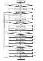
- FIG. 1is a diagram showing a treatment system 1 according to the first embodiment.
- FIG. 2is a block diagram showing the configuration of the treatment system 1.
- the treatment system 1treats the target site by applying ultrasonic energy and high frequency energy to the target site (hereinafter referred to as the target site) in the living tissue.
- the proceduremeans, for example, coagulation and incision of the target site.
- the treatment system 1includes a treatment tool 2, a generator 3, and an inspection sheet 4 (see FIG. 4).
- the sheath 6has a substantially cylindrical shape as a whole. Then, the sheath 6 is attached to the holding case 5 by inserting a part of the proximal end side Ar2 from the distal end side Ar1 of the holding case main body 51 into the inside of the holding case main body 51.
- the processor 15calculates the control parameter (treatment drive current) as shown below.
- the processor 15inspects the ultrasonic vibrator 82 supplied in steps S7 to S11 based on the treatment completion time measured in steps S8 to S12 and the characteristic data stored in the first memory 16. It is possible to grasp how much vibration amplitude (hereinafter, referred to as vibration amplitude at the time of inspection) actually vibrates in the treatment unit 91 by the driving current.
- the processor 15since the treatment completion time measured in steps S8 to S12 is 5 [s], the processor 15 has 90 [ ⁇ m] corresponding to the 5 [s] on the curve CL0 as the vibration amplitude at the time of inspection. Know that there is.
- the points of the treatment completion time and the vibration amplitude during the inspection measured in steps S8 to S12are indicated by points P0.
- FIG. 10is a diagram illustrating step S13A.
- FIG. 10is a diagram in which the vibration amplitude [ ⁇ m] of the ultrasonic vibration is on the horizontal axis and the treatment completion time [s] is on the vertical axis, as in FIG. 7.
- a plurality of characteristic dataare stored in the first memory 16.
- the plurality of characteristic dataare characteristic data corresponding to a plurality of different gripping forces by the jaw 7 and the treatment unit 91, and in the example of FIG. 10, they are the data shown by the curves CL1 to CL3, respectively.
- the characteristic data shown by the curve CL1 in FIG. 10is characteristic data corresponding to the case where the gripping force is 15 [N]. Further, the characteristic data shown by the curve CL2 in FIG.
- the processor 15has a first treatment completion time in which the first layer 41 is incised by the vibration amplitude of ultrasonic vibration corresponding to the first inspection drive current, and a second inspection.
- the reference temperature stored in the first memory 16is a temperature that serves as a reference value for the treatment surface temperature.
- the reference temperatureis a temperature set to reduce the load on the treatment tool 2 due to heat to a specific load or less.
- the reference temperature TH3is set to 290 [° C.].
- the relationship between the heater resistance and the treated surface temperatureis a linear relationship.
- the second slope information stored in the first memory 16is the ratio of the fluctuation amount of the treatment surface temperature to the fluctuation amount of the heater resistance in the linear relationship (the linear relationship). Information indicating the slope in the relationship).
Landscapes
- Health & Medical Sciences (AREA)
- Engineering & Computer Science (AREA)
- Surgery (AREA)
- Life Sciences & Earth Sciences (AREA)
- Public Health (AREA)
- General Health & Medical Sciences (AREA)
- Medical Informatics (AREA)
- Biomedical Technology (AREA)
- Nuclear Medicine, Radiotherapy & Molecular Imaging (AREA)
- Animal Behavior & Ethology (AREA)
- Veterinary Medicine (AREA)
- Molecular Biology (AREA)
- Heart & Thoracic Surgery (AREA)
- Physics & Mathematics (AREA)
- Plasma & Fusion (AREA)
- Otolaryngology (AREA)
- Epidemiology (AREA)
- Primary Health Care (AREA)
- General Business, Economics & Management (AREA)
- Business, Economics & Management (AREA)
- Dentistry (AREA)
- Mechanical Engineering (AREA)
- Urology & Nephrology (AREA)
- Ophthalmology & Optometry (AREA)
- Surgical Instruments (AREA)
Abstract
Description
Translated fromJapanese本発明は、処置システム及び制御パラメータ算出方法に関する。The present invention relates to a treatment system and a control parameter calculation method.
従来、生体組織における処置の対象となる部位(以下、対象部位と記載)に対して処置エネルギを付与することによって当該対象部位を処置する処置システムが知られている(例えば、特許文献1参照)。
特許文献1に記載の処置システム(超音波手術装置)では、処置エネルギとして、超音波エネルギを採用している。すなわち、当該処置システムでは、対象部位に対して超音波振動を付与することによって当該対象部位を処置している。また、当該処置システムでは、シェルフライフ等によって当該超音波振動の振動振幅が出荷時から変化してしまう課題に対して、キャビテーションを利用することによってキャリブレーションを行っている。Conventionally, a treatment system for treating a target site in a living tissue by applying treatment energy to a target site (hereinafter referred to as a target site) has been known (see, for example, Patent Document 1). ..
The treatment system (ultrasonic surgical apparatus) described in
しかしながら、特許文献1に記載の処置システムでは、キャリブレーションを行ったとしても、実際に対象部位を処置する際の処置エネルギの強度に関する制御パラメータ(実際に対象部位を処置する際に当該対象部位に付与する超音波振動の振動振幅を規定する駆動電流)は不明なままである。このため、所望の処置性能を得ることが難しい、という問題がある。However, in the treatment system described in
本発明は、上記に鑑みてなされたものであって、所望の処置性能を得ることができる処置システム及び制御パラメータ算出方法を提供することを目的とする。The present invention has been made in view of the above, and an object of the present invention is to provide a treatment system and a control parameter calculation method capable of obtaining desired treatment performance.
上述した課題を解決し、目的を達成するために、本発明に係る処置システムは、供給された電力に応じて発生した処置エネルギを生体組織に対して付与する処置具と、ジェネレータと、を備え、前記処置具は、前記処置エネルギを前記生体組織に対して付与する第1の把持部材と、前記第1の把持部材との間で前記生体組織を把持する第2の把持部材と、を有し、前記ジェネレータは、前記処置具に対して前記電力を供給する電源回路と、前記第1の把持部材及び前記第2の把持部材の間に把持され、前記第1の把持部材から前記処置エネルギが付与された検査部材の処置状態を示す指標値を検出する検出回路と、前記指標値に基づいて、前記検査部材に対する前記処置エネルギの付与が開始されてから前記検査部材における特定の処置が完了するまでの処置完了時間を測定するプロセッサと、を有し、前記処置具及び前記ジェネレータの少なくとも一方は、前記検査部材の特性を示すデータであって、前記検査部材に対して付与される前記処置エネルギの強度と前記処置完了時間との関係を示す特性データを記憶する第1のメモリをさらに有し、前記プロセッサは、測定した前記処置完了時間と、前記検査部材に対して付与した前記処置エネルギの強度と、前記特性データとに基づいて、前記生体組織を処置する際の前記処置エネルギの強度に関する制御パラメータを算出する。In order to solve the above-mentioned problems and achieve the object, the treatment system according to the present invention includes a treatment tool and a generator that apply treatment energy generated according to the supplied electric power to the living tissue. The treatment tool includes a first gripping member that applies the treatment energy to the living body tissue, and a second gripping member that grips the living body tissue between the first gripping member. Then, the generator is gripped between the power supply circuit that supplies the electric power to the treatment tool, the first grip member, and the second grip member, and the treatment energy is obtained from the first grip member. Based on the detection circuit that detects the index value indicating the treatment state of the inspection member to which is given, and the index value, the specific treatment in the inspection member is completed after the application of the treatment energy to the inspection member is started. It has a processor for measuring the treatment completion time until the treatment is completed, and at least one of the treatment tool and the generator is data indicating the characteristics of the inspection member, and the treatment given to the inspection member. The processor further has a first memory for storing characteristic data indicating the relationship between the energy intensity and the treatment completion time, and the processor has measured the treatment completion time and the treatment energy given to the inspection member. Based on the intensity of the above and the characteristic data, a control parameter relating to the intensity of the treatment energy when treating the living tissue is calculated.
また、本発明に係る制御パラメータ算出方法は、ジェネレータのプロセッサが実行する制御パラメータ算出方法であって、第1の把持部材及び第2の把持部材の間に把持され前記第1の把持部材から処置エネルギが付与された検査部材の処置状態を示す指標値に基づいて、前記検査部材に対する前記処置エネルギの付与が開始されてから前記検査部材における特定の処置が完了するまでの処置完了時間を測定し、測定した前記処置完了時間と、前記検査部材に対して付与した前記処置エネルギの強度と、前記検査部材の特性を示すデータであって、前記検査部材に対して付与される前記処置エネルギの強度と前記処置完了時間との関係を示す特性データとに基づいて、生体組織を処置する際の前記処置エネルギの強度に関する制御パラメータを算出し、前記特性データは、前記検査部材に対して付与される前記処置エネルギの強度と前記処置完了時間との関係を示すデータである。Further, the control parameter calculation method according to the present invention is a control parameter calculation method executed by the processor of the generator, and is gripped between the first grip member and the second grip member and treated from the first grip member. Based on the index value indicating the treatment state of the inspection member to which the energy is applied, the treatment completion time from the start of applying the treatment energy to the inspection member to the completion of the specific treatment in the inspection member is measured. Data showing the measured treatment completion time, the intensity of the treatment energy applied to the inspection member, and the characteristics of the inspection member, the intensity of the treatment energy applied to the inspection member. Based on the characteristic data indicating the relationship between the treatment completion time and the treatment completion time, control parameters relating to the intensity of the treatment energy when treating the biological tissue are calculated, and the characteristic data is given to the inspection member. It is data which shows the relationship between the intensity of the treatment energy and the treatment completion time.
本発明に係る処置システム及び制御パラメータ算出方法によれば、所望の処置性能を得ることができる。According to the treatment system and the control parameter calculation method according to the present invention, desired treatment performance can be obtained.
以下に、図面を参照しつつ、本発明を実施するための形態(以下、実施の形態)について説明する。なお、以下に説明する実施の形態によって本発明が限定されるものではない。さらに、図面の記載において、同一の部分には同一の符号を付している。Hereinafter, embodiments for carrying out the present invention (hereinafter referred to as embodiments) will be described with reference to the drawings. The present invention is not limited to the embodiments described below. Further, in the description of the drawings, the same parts are designated by the same reference numerals.
(実施の形態1)
〔処置システムの概略構成〕
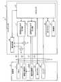
図1は、実施の形態1に係る処置システム1を示す図である。図2は、処置システム1の構成を示すブロック図である。
処置システム1は、生体組織における処置の対象となる部位(以下、対象部位と記載)に対して超音波エネルギ及び高周波エネルギを付与することによって、当該対象部位を処置する。当該処置とは、例えば、対象部位の凝固及び切開を意味する。この処置システム1は、図1または図2に示すように、処置具2と、ジェネレータ3と、検査シート4(図4参照)とを備える。(Embodiment 1)
[Outline configuration of treatment system]
FIG. 1 is a diagram showing a
The
〔処置具の構成〕
なお、以下では、処置具2の構成を説明するにあたって、シース6の中心軸Ax(図1)に沿う一方側を先端側Ar1と記載し、他方側を基端側Ar2と記載する。
処置具2は、例えば、腹壁を通した状態で対象部位を処置する医療用処置具であり、電気ケーブルCによってジェネレータ3に対して着脱自在に接続される。この処置具2は、図1または図2に示すように、保持ケース5と、シース6と、ジョー7と、振動子ユニット8と、振動伝達部材9とを備える。
保持ケース5は、処置具2全体を支持する。この保持ケース5は、図1に示すように、中心軸Axと同軸となる略円筒状の保持ケース本体51と、当該保持ケース本体51から図1中、下方側に延在し、術者等の操作者によって把持される固定ハンドル52とを備える。[Structure of treatment tool]
In the following description of the configuration of the
The
The
この保持ケース5には、図1に示すように、可動ハンドル53と、スイッチ54とが設けられている。
可動ハンドル53は、術者等の操作者による開閉操作を受け付ける部分であり、固定ハンドル52に対して近接及び離間する各方向にそれぞれ移動可能に設けられている。
スイッチ54は、術者等の操作者による出力開始操作を受け付ける部分である。そして、スイッチ54は、電気ケーブルCを経由することによって、当該出力開始操作に応じた操作信号をジェネレータ3に対して出力する。As shown in FIG. 1, the
The
The
また、保持ケース5の内部には、第2のメモリ55(図2)が設けられている。
第2のメモリ55は、ジェネレータ3による制御パラメータの算出履歴(制御パラメータの算出回数等)を示す履歴情報、及びジェネレータ3によって算出された制御パラメータ等を記憶する。当該制御パラメータの詳細については後述する。A second memory 55 (FIG. 2) is provided inside the
The
シース6は、全体略円筒形状を有する。そして、シース6は、基端側Ar2の一部が保持ケース本体51における先端側Ar1から当該保持ケース本体51の内部に挿入されることによって、保持ケース5に対して取り付けられる。The
図3は、ジョー7の構成を示す図である。具体的に、図3は、中心軸Axに直交する平面によってジョー7及び振動伝達部材9を切断した断面図である。
ジョー7は、シース6における先端側Ar1の端部に対して回転可能に取り付けられ、振動伝達部材9における先端側Ar1の端部(処置部91(図1))との間で対象部位を把持する。なお、上述した保持ケース本体51及びシース6の内部には、術者等の操作者による可動ハンドル53への開閉操作に応じて、処置部91に対してジョー7を開閉させる開閉機構(図示略)が設けられている。このジョー7は、図3に示すように、導電性材料によって構成され、シース6に対して回転可能に取り付けられるジョー本体71と、当該ジョー本体71における振動伝達部材9に対向する面に取り付けられた樹脂製のパッド72とを備える。当該パッド72は、絶縁性を有するため、対象部位の切開が完了し、ジョー7が振動伝達部材9に対して当接した状態となっても、ジョー本体71と振動伝達部材9とが短絡することを防止する機能を有する。また、当該パッド72は、対象部位の切開が完了し、ジョー7が振動伝達部材9に対して当接した状態となっても、超音波振動している振動伝達部材9がジョー本体71に衝突することによって破損することを防止する機能も有する。
そして、ジョー7は、本発明に係る第2の把持部材に相当する。FIG. 3 is a diagram showing the configuration of the
The
The
振動子ユニット8は、図1または図2に示すように、振動子ケース81(図1)と、超音波振動子82(図2)とを備える。
振動子ケース81は、中心軸Axに沿って直線状に延在し、先端側Ar1の端部が保持ケース本体51における基端側Ar2から当該保持ケース本体51の内部に挿入されることによって、保持ケース5に対して取り付けられる。
超音波振動子82は、振動子ケース81の内部に収納され、当該振動子ケース81が保持ケース5に対して取り付けられた状態で、ホーン(図示略)を経由することによって、振動伝達部材9における基端側Ar2の端部に対して機械的に接続される。この超音波振動子82は、ジェネレータ3による制御の下、超音波振動を発生させる。本実施の形態1では、当該超音波振動は、中心軸Axに沿う方向に振動する縦振動である。この超音波振動子82は、具体的な図示は省略したが、中心軸Axに沿って積層された複数の圧電素子を備えたBLT(ボルト締めランジュバン型振動子)によって構成されている。As shown in FIG. 1 or 2, the
The
The
振動伝達部材9は、導電性材料によって構成され、中心軸Axに沿って直線状に延在する長尺形状を有し、図1に示すように、処置部91が外部に突出した状態でシース6の内部に挿通される。また、振動伝達部材9における基端側Ar2の端部は、ホーン(図示略)を経由することによって、超音波振動子82に対して機械的に接続する。そして、振動伝達部材9は、超音波振動子82が発生させた超音波振動を基端側Ar2の端部から処置部91まで伝達し、当該処置部91から対象部位に対して当該超音波振動を付与することによって当該対象部位を処置する。言い換えれば、振動伝達部材9は、処置部91から対象部位に対して超音波エネルギを付与することによって当該対象部位を処置する。すなわち、振動伝達部材9は、本発明に係る第1の把持部材に相当する。また、当該超音波エネルギは、本発明に係る処置エネルギに相当する。The
〔ジェネレータの構成〕
ジェネレータ3は、電気ケーブルCを経由することによって、処置具2の動作を統括的に制御する。このジェネレータ3は、図2に示すように、超音波エネルギ出力部10と、高周波エネルギ出力部11と、電圧検出部12と、電流検出部13と、検出回路14と、プロセッサ15と、第1のメモリ16と、報知部17とを備える。[Generator configuration]
The
超音波エネルギ出力部10は、電気ケーブルCによってジェネレータ3に対して処置具2が接続されると、当該電気ケーブルCを構成する一対の第1の電流経路C1,C1´(図2)を経由することによって超音波振動子82に対して電気的に接続される。そして、超音波エネルギ出力部10は、プロセッサ15による制御の下、一対の電流経路C1,C1´を経由することによって、超音波振動子82に対して交流電力(処置部91の振動振幅を規定する駆動電流)を供給する。これによって、超音波振動子82は、超音波振動を発生させる。そして、処置部91は、当該駆動電流に応じた振動振幅で振動する。すなわち、超音波エネルギ出力部10は、本発明に係る電源回路に相当する。When the
高周波エネルギ出力部11は、電気ケーブルCによってジェネレータ3に対して処置具2が接続されると、当該電気ケーブルCを構成する一対の第2の電流経路C2,C2´(図2)を経由することによってジョー本体71及び振動伝達部材9に対して電気的に接続される。そして、高周波エネルギ出力部11は、プロセッサ15による制御の下、一対の第2の電流経路C2,C2´を経由することによって、ジョー本体71及び振動伝達部材9との間に高周波電圧及び高周波電流を供給する。これによって、ジョー本体71と処置部91との間に把持された対象部位には、高周波電流が流れる。言い換えれば、当該対象部位には、高周波エネルギが付与される。すなわち、ジョー本体71と振動伝達部材9とは、高周波電極としても機能する。When the
電圧検出部12は、一対の第2の電流経路C2,C2´を経由することによって高周波エネルギ出力部11からジョー本体71及び振動伝達部材9に対して供給されている高周波電圧を順次、検出する。そして、電圧検出部12は、当該検出した高周波電圧に応じたHF電圧信号を検出回路14に対して出力する。
電流検出部13は、一対の第2の電流経路C2,C2´を経由することによって高周波エネルギ出力部11からジョー本体71及び振動伝達部材9に対して供給されている高周波電流を順次、検出する。そして、電流検出部13は、当該検出した高周波電流に応じたHF電流信号を検出回路14に対して出力する。The
The
検出回路14は、電圧検出部12から出力されるHF電圧信号と電流検出部13から出力されるHF電流信号とに基づいて、ジョー7と振動伝達部材9における先端側Ar1の部位との間に把持された対象部位や検査シート4のインピーダンス値(以下、HFインピーダンスと記載)を検出する。当該HFインピーダンスは、本発明に係る「検査部材の処置状態を示す指標値」に相当する。そして、検出回路14は、検出したHFインピーダンスをプロセッサ15に対して出力する。The
プロセッサ15は、例えば、CPU(Central Processing Unit)やFPGA(Field-Programmable Gate Array)等であり、第1のメモリ16に記憶されたプログラムにしたがって、処置システム1全体の動作を制御する。なお、プロセッサ15の詳細な機能については、後述する「制御パラメータ算出方法」において説明する。
第1のメモリ16は、プロセッサ15が実行するプログラムや、プロセッサ15の処理に必要な情報等を記憶する。当該プロセッサ15の処理に必要な情報としては、検査シート4の特性を示す特性データと、基準完了時間と、基準振幅と、第1のスロープ情報とを例示することができる。なお、当該特性データ、当該基準完了時間、当該基準振幅、及び当該第1のスロープ情報の詳細については、後述する「制御パラメータ算出方法」において説明する。The
The
報知部17は、プロセッサ15による制御の下、所定の情報を報知する。この報知部17としては、例えば、点灯や点滅、あるいは、点灯した際の色によって所定の情報を報知するLED(Light Emitting Diode)、所定の情報を表示する表示装置、所定の情報を音声によって出力するスピーカ等を例示することができる。The notification unit 17 notifies predetermined information under the control of the
〔検査シートの構成〕
図4は、検査シート4の構成を示す図である。
検査シート4は、後述する制御パラメータ算出方法において、制御パラメータを算出する際に用いられる。当該制御パラメータは、対象部位を処置する際に当該対象部位に対して付与する処置エネルギの強度に関する制御パラメータである。本実施の形態1では、当該制御パラメータは、対象部位を処置する際に当該対象部位に対して付与する超音波振動の振動振幅(処置部91の振動振幅)を規定する駆動電流(対象部位を処置する際に超音波振動子82に対して供給する駆動電流(以下、処置用駆動電流と記載))である。すなわち、当該制御パラメータは、超音波振動の振動振幅に関するパラメータであり、本発明に係る超音波パラメータに相当する。
この検査シート4は、図4に示すように、第1の層41と、第2の層42とが積層されたシートによって構成されている。[Structure of inspection sheet]
FIG. 4 is a diagram showing the configuration of the
The
As shown in FIG. 4, the
第1の層41は、高耐熱(例えば、融点:270℃以上)の熱可塑性樹脂によって構成されている。なお、第1の層41は、付与される超音波エネルギに対して、実際に処置を行う対象部位と同等の特性を有する。
第2の層42は、アルミ箔等の導電性材料によって構成されている。なお、第2の層42としては、メッキによって構成してもよく、あるいは、高耐熱(例えば、融点:400℃)の導電性ゴムによって構成しても構わない。The
The
〔制御パラメータ算出方法〕
次に、プロセッサ15が実行する制御パラメータ算出方法について説明する。
なお、以下において説明する制御パラメータ算出方法は、実際に処置具2が用いられる病院等の現地において実行されるものである。
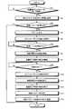
図5は、制御パラメータ算出方法を示すフローチャートである。
先ず、プロセッサ15は、電気ケーブルCによって処置具2がジェネレータ3に対して接続されたか否かを常時、監視する(ステップS1)。
処置具2が接続されたと判定した場合(ステップS1:Yes)には、プロセッサ15は、電気ケーブルCを経由することによって、第2のメモリ55に記憶された情報を参照する(ステップS2)。[Control parameter calculation method]
Next, the control parameter calculation method executed by the
The control parameter calculation method described below is executed at a site such as a hospital where the
FIG. 5 is a flowchart showing a control parameter calculation method.
First, the
When it is determined that the
ステップS2の後、プロセッサ15は、第2のメモリ55に記憶された情報を参照した結果、当該第2のメモリ55に制御パラメータが記憶されているか否か、すなわち、既に制御パラメータを算出済であるか否かを判定する(ステップS3)。
制御パラメータを算出済であると判定した場合(ステップS3:Yes)には、プロセッサ15は、本制御フローを終了する。
一方、制御パラメータを算出済ではないと判定した場合(ステップS3:No)には、プロセッサ15は、報知部17の動作を制御し、処置具2によって検査シート4を把持する旨を当該報知部17から報知(アラーム出力)させる(ステップS4)。After step S2, as a result of referring to the information stored in the
When it is determined that the control parameters have been calculated (step S3: Yes), the
On the other hand, when it is determined that the control parameters have not been calculated (step S3: No), the
そして、術者等の操作者は、当該報知に応じて、処置具2を手で持ち、可動ハンドル53に対して開閉操作を行う。これによって、検査シート4は、第1の層41が振動伝達部材9側に位置し、第2の層42がジョー7側に位置する姿勢でジョー7と処置部91との間に把持される。Then, the operator such as the operator holds the
ステップS4の後、プロセッサ15は、高周波エネルギ出力部11の動作を制御することによって、ジョー本体71及び振動伝達部材9に対して一定の高周波電力を供給する。当該一定の高周波電力とは、検査シート4が熱変性しない程度の電力である。そして、プロセッサ15は、検出回路14の動作を制御し、HFインピーダンスの検出を開始させる(ステップS5)。After step S4, the
ステップS5の後、プロセッサ15は、検出回路14によって検出されたHFインピーダンスに基づいて、処置具2によって検査シート4が把持されたか否かを常時、監視する(ステップS6)。
検査シート4が把持されたと判定した場合(ステップS6:Yes)には、プロセッサ15は、超音波エネルギ出力部10の動作を制御することによって、超音波振動子82に対して検査用電力(検査用駆動電流)の供給を開始する(ステップS7)。これによって、超音波振動子82は、超音波振動を発生させる。そして、処置部91は、当該検査用駆動電流に応じた振動振幅で振動する。なお、当該検査用駆動電流は、本発明に係る「検査部材に対して付与した処置エネルギの強度」に相当する。そして、検査シート4に対して処置部91から当該超音波振動が付与されることによって第1の層41の切開が開始される。
また、プロセッサ15は、ステップS7と同時に、第1の層41の切開が完了する時間(以下、処置完了時間と記載)の測定を開始する(ステップS8)。After step S5, the
When it is determined that the
Further, the
ステップS8の後、プロセッサ15は、第1の層41の切開が完了したか否かを常時、監視する(ステップS9)。第1の層41の切開は、本発明に係る「検査部材における特定の処置」に相当する。
図6は、ステップS9を説明する図である。具体的に、図6は、ステップS7,S8以降におけるHFインピーダンスの挙動を示す図である。
ここで、ステップS7,S8以降におけるHFインピーダンスは、図6に示すように、第1の層41が徐々に薄くなっていくことに伴って、徐々に減少していく。そして、第1の層41が切開されると、第2の層42によってジョー本体71と振動伝達部材9とは導通する。すなわち、HFインピーダンスは、第1の層41が切開されると(図6に示す時間T1の時点)、急激に減少する。
本実施の形態1では、プロセッサ15は、ステップS9において、検出回路14によって検出されたHFインピーダンスに上述した挙動(急激な減少)が生じた場合に、第1の層41の切開が完了したと判定する。After step S8, the
FIG. 6 is a diagram illustrating step S9. Specifically, FIG. 6 is a diagram showing the behavior of the HF impedance in steps S7 and S8 and thereafter.
Here, as shown in FIG. 6, the HF impedance in steps S7 and S8 and thereafter gradually decreases as the
In the first embodiment, the
第1の層41の切開が完了したと判定した場合(ステップS9:Yes)には、プロセッサ15は、高周波エネルギ出力部11及び検出回路14の動作を停止し、HFインピーダンスの検出を終了する(ステップS10)。
また、プロセッサ15は、ステップS10と同時に、超音波エネルギ出力部10の動作を停止し、超音波振動子82への検査用電力の供給を終了する(ステップS11)。
さらに、プロセッサ15は、ステップS10,S11と同時に、処置完了時間の測定を終了する(ステップS12)。When it is determined that the incision of the
Further, at the same time as step S10, the
Further, the
ステップS12の後、プロセッサ15は、ステップS8~S12において測定した処置完了時間と、ステップS7~S11において超音波振動子82に対して供給した検査用駆動電流と、第1のメモリ16に記憶された特性データ、基準完了時間、基準振幅、及び第1のスロープ情報とに基づいて、制御パラメータ(処置用駆動電流)を算出する(ステップS13)。
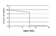
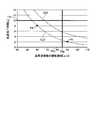
図7は、ステップS13を説明する図である。具体的に、図7は、超音波振動の振動振幅[μm]を横軸とし、処置完了時間[s]を縦軸とした図である。
ここで、第1のメモリ16に記憶された特性データは、図7の例では、曲線CL0によって示されるデータである。具体的に、当該特性データは、検査シート4に対して付与される超音波振動の振動振幅と当該振動振幅の超音波振動を当該検査シート4に対して付与してから当該検査シート4の第1の層41が切開されるまでの処置完了時間との関係を示すデータである。図7の曲線CL0では、振動振幅が100[μm]の超音波振動を検査シート4に対して付与すると、当該検査シート4の第1の層41は、4[s]の処置完了時間で切開されることを示している。また、図7の曲線CL0では、振動振幅が60[μm]の超音波振動を検査シート4に対して付与すると、当該検査シート4の第1の層41は、12[s]の処置完了時間で切開されることを示している。After step S12, the
FIG. 7 is a diagram illustrating step S13. Specifically, FIG. 7 is a diagram in which the vibration amplitude [μm] of ultrasonic vibration is on the horizontal axis and the treatment completion time [s] is on the vertical axis.
Here, the characteristic data stored in the
また、第1のメモリ16に記憶された基準完了時間は、処置完了時間の基準値となる時間である。なお、当該基準完了時間は、少なくとも当該基準完了時間以下で処置を完了したいというユーザの要望に応じた時間である。図7の例では、当該基準完了時間TH1は、10[s]に設定されている。
さらに、第1のメモリ16に記憶された基準振幅は、処置部91の振動振幅の基準値となる振動振幅である。なお、当該基準振幅は、超音波振動による処置具2への負荷を特定の負荷以下とするために設定された振動振幅である。図7の例では、当該基準振幅TH2は、85[μm]に設定されている。
また、超音波振動子82に対して供給する駆動電流と処置部91の振動振幅との関係は、線形の関係である。そして、第1のメモリ16に記憶された第1のスロープ情報は、当該線形の関係において、駆動電流の変動量に対する処置部91の振動振幅の変動量の比率(当該線形の関係における傾き)を示す情報である。Further, the reference completion time stored in the
Further, the reference amplitude stored in the
Further, the relationship between the drive current supplied to the
そして、プロセッサ15は、ステップS13において、以下に示すように、制御パラメータ(処置用駆動電流)を算出する。
先ず、プロセッサ15は、ステップS8~S12において測定した処置完了時間と、第1のメモリ16に記憶された特性データとに基づいて、ステップS7~S11において超音波振動子82に対して供給した検査用駆動電流によって、実際に処置部91がどの程度の振動振幅(以下、検査時振動振幅と記載)で振動したかを把握する。図7の例では、ステップS8~S12において測定した処置完了時間が5[s]であるため、プロセッサ15は、曲線CL0における当該5[s]に対応する90[μm]が検査時振動振幅であると把握する。図7の例では、ステップS8~S12において測定した処置完了時間及び当該検査時振動振幅の点を点P0によって示している。Then, in step S13, the
First, the
次に、プロセッサ15は、第1のメモリ16に記憶された特性データ、基準完了時間、及び基準振幅に基づいて、対象部位を処置する際での処置部91の振動振幅(以下、処置時振動振幅と記載)を設定する。具体的に、プロセッサ15は、特性データを示す曲線CL0における基準完了時間以下の処置完了時間に対応する振動振幅であって、基準振幅以下となる振動振幅を処置時振動振幅に設定する。図7の例では、曲線CL0における基準完了時間TH1である10[s]に対応する68[μm]以上、基準振幅TH2である85[μm]以下の範囲である例えば80[μm]を処置時振動振幅TA1とする。Next, the
そして、プロセッサ15は、ステップS7~S11において超音波振動子82に対して供給した検査用駆動電流と上記のように把握した検査時振動振幅との対応関係と、第1のメモリ16に記憶された第1のスロープ情報(駆動電流の変動量に対する処置部91の振動振幅の変動量の比率を示す情報)とに基づいて、上記のように設定した処置時振動振幅TA1を得るために必要な処置用駆動電流(制御パラメータ)を算出する。Then, the
ステップS13の後、プロセッサ15は、電気ケーブルCを経由することによって、ステップS12において算出した制御パラメータ(処置用駆動電流)を第2のメモリ55に記憶するとともに、当該第2のメモリ55に記憶された履歴情報を更新する(ステップS14)。この後、プロセッサ15は、本制御フローを終了する。After step S13, the
そして、プロセッサ15は、術者等の操作者によるスイッチ54への出力開始操作に応じて対象部位を処置する際には、第2のメモリ55に記憶された制御パラメータ(処置用駆動電流)を参照し、当該処置用駆動電流を超音波振動子82に対して供給させる。これによって、処置部91は、処置時振動振幅TA1で超音波振動し、当該超音波振動を対象部位に対して付与することになる。Then, when the
以上説明した処置システム1を構成する処置具2は、1回の使用後に処分される構成としてもよいし、複数回繰り返し使用される構成としても構わない。当該複数回繰り返し使用される構成とする場合には、例えば、図8に示すリプロセス方法による再製造が必要となる。The
〔リプロセス方法〕
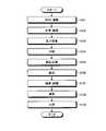
図8は、リプロセス方法を示すフローチャートである。
先ず、再製造を行う製造販売者は、処置に使用した後の使用済み処置具2を回収し、工場等に運搬する(工程S101)。次に、製造販売者は、回収、運搬された使用済みの処置具2を洗浄・滅菌し(工程S102)、受入検査を行う(工程S103)。次に、製造販売者は、処置具2を分解するとともに(工程S104)、特定の部品(処置により消耗した部品、または、汚れが付着した部品)を新品に交換する作業が行われる(工程S105)。その後、製造販売者は、各部品を再び組み立て(工程S106)、検査・試験(工程S107)及び滅菌(工程S108)を経た後、再び出荷される(工程S109)。
なお、再製造後は、第2のメモリ55に記憶されていた制御パラメータ(処置用駆動電流)は、消去される。[Reprocess method]
FIG. 8 is a flowchart showing the reprocess method.
First, the manufacturer / seller who remanufactures collects the used
After the remanufacturing, the control parameters (treatment drive current) stored in the
以上説明した本実施の形態1によれば、以下の効果を奏する。
本実施の形態1に係る処置システム1を構成するジェネレータ3は、ジョー7及び処置部91の間に把持された検査シート4に対して当該処置部91から超音波エネルギを付与しつつ、当該検査シート4の処置状態を示す指標値(HFインピーダンス)を検出する。また、ジェネレータ3を構成するプロセッサ15は、当該指標値に基づいて、検査シート4における特定の処置が完了するまでの処置完了時間を測定する。そして、プロセッサ15は、測定した処置完了時間と、検査用駆動電流と、第1のメモリ16に記憶された特性データとに基づいて、対象部位を処置する際の超音波エネルギの強度に関する制御パラメータ(超音波振動の振動振幅を規定する駆動電流)を算出する。
したがって、対象部位を処置する際に当該制御パラメータを用いれば、所望の処置完了時間で当該対象部位を処置することができ、所望の処置性能を得ることができる。According to the first embodiment described above, the following effects are obtained.
The
Therefore, if the control parameter is used when treating the target site, the target site can be treated in a desired treatment completion time, and the desired treatment performance can be obtained.
また、処置システム1を構成する処置具2は、制御パラメータの算出履歴を示す履歴情報を記憶する第2のメモリ55を備える。
したがって、処置具2の再製造を行う製造販売者は、工程S103において、当該履歴情報を参照すれば、再製造回数を把握することができる。すなわち、製造販売者は、当該履歴情報を参照すれば、上限となる最大再製造回数を超えた処置具2であるか否かを判別することができる。また、実際に処置具2が用いられる病院等の現地において制御パラメータ算出方法が実行されるため、リプロセス方法を構成する例えば工程S107の検査・試験等を簡略化することも可能となる。Further, the
Therefore, the manufacturer / seller who remanufactures the
(実施の形態2)
次に、本実施の形態2について説明する。
以下の説明では、上述した実施の形態1と同様の構成には同一符号を付し、その詳細な説明は省略または簡略化する。
図9は、実施の形態2に係る制御パラメータ算出方法を示すフローチャートである。
本実施の形態2では、図9に示すように、上述した実施の形態1に対して、制御パラメータ算出方法が異なる。(Embodiment 2)
Next, the second embodiment will be described.
In the following description, the same components as those in the first embodiment will be designated by the same reference numerals, and detailed description thereof will be omitted or simplified.
FIG. 9 is a flowchart showing a control parameter calculation method according to the second embodiment.
In the second embodiment, as shown in FIG. 9, the control parameter calculation method is different from that of the first embodiment described above.
本実施の形態2に係る制御パラメータ算出方法では、図9に示すように、上述した実施の形態1において説明した制御パラメータ算出方法(図5)に対して、ステップS15が追加されているとともに、ステップS13の代わりにステップS13Aが採用されている。このため、以下では、ステップS15,S13Aを主に説明する。In the control parameter calculation method according to the second embodiment, as shown in FIG. 9, step S15 is added to the control parameter calculation method (FIG. 5) described in the above-described first embodiment, and step S15 is added. Step S13A is adopted instead of step S13. Therefore, in the following, steps S15 and S13A will be mainly described.
ステップS15は、ステップS12の後に実行される。
プロセッサ15は、ステップS15において、ステップS4~S12のループを2回、行ったか否かを判定する。
具体的に、本実施の形態2では、付与される超音波エネルギに対して互いに同一の特性を有する2枚の検査シート4を用いる(ステップS4~S12の1回目のループにおいて2枚の検査シート4のうち一方の検査シート4を用い、2回目のループにおいて他方の検査シート4を用いる)。また、超音波振動子82に対して異なる値の検査用駆動電流を供給し、当該2枚の検査シート4に対して異なる振動振幅の超音波振動をそれぞれ付与する。そして、当該2枚の検査シート4の各第1の層41が切開されるまでの各処置完了時間をそれぞれ測定する。Step S15 is executed after step S12.
In step S15, the
Specifically, in the second embodiment, two
以下では、ステップS4~S12の1回目のループ中、ステップS7~S11において超音波振動子82に対して供給した検査用駆動電流を第1の検査用駆動電流と記載し、ステップS8~S12において測定した処置完了時間を第1の処置完了時間と記載する。また、ステップS4~S12の2回目のループ中、ステップS7~S11において超音波振動子82に対して供給した検査用駆動電流を第2の検査用駆動電流と記載し、ステップS8~S12において測定した処置完了時間を第2の処置完了時間と記載する。ここで、第1の検査用駆動電流は、本発明に係る第1の強度に相当する。また、第2の検査用駆動電流は、本発明に係る第2の強度に相当する。In the following, the inspection drive current supplied to the
ステップS13Aは、ステップS15においてステップS4~S12のループを2回、行ったと判定された場合に実行される。
具体的に、プロセッサ15は、ステップS13Aにおいて、第1,第2の処置完了時間と、第1,第2の検査用駆動電流と、第1のメモリ16に記憶された複数の特性データ、基準完了時間、基準振幅、及び第1のスロープ情報とに基づいて、制御パラメータ(処置用駆動電流)を算出する。この後、プロセッサ15は、ステップS14に移行する。Step S13A is executed when it is determined in step S15 that the loop of steps S4 to S12 has been performed twice.
Specifically, in step S13A, the
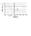
図10は、ステップS13Aを説明する図である。具体的に、図10は、図7と同様に、超音波振動の振動振幅[μm]を横軸とし、処置完了時間[s]を縦軸とした図である。
本実施の形態2では、第1のメモリ16には、特性データが複数、記憶されている。当該複数の特性データは、ジョー7と処置部91とによる互いに異なる複数の把持力にそれぞれ対応した特性データであり、図10の例では、曲線CL1~CL3によってそれぞれ示すデータである。図10の曲線CL1で示す特性データは、当該把持力を15[N]とした場合に対応した特性データである。また、図10の曲線CL2で示す特性データは、当該把持力を20[N]とした場合に対応した特性データである。さらに、図10の曲線CL3で示す特性データは、当該把持力を25[N]とした場合に対応した特性データである。曲線CL1~CL3から分かるように、検査シート4に対して付与する超音波振動の振動振幅が同一であっても当該把持力が異なれば処置完了時間が異なるものとなる(当該把持力が大きいほど処置完了時間が短くなる)ことが分かる。FIG. 10 is a diagram illustrating step S13A. Specifically, FIG. 10 is a diagram in which the vibration amplitude [μm] of the ultrasonic vibration is on the horizontal axis and the treatment completion time [s] is on the vertical axis, as in FIG. 7.
In the second embodiment, a plurality of characteristic data are stored in the
そして、プロセッサ15は、ステップS13Aにおいて、以下に示すように、制御パラメータ(処置用駆動電流)を算出する。
先ず、プロセッサ15は、第1の処置完了時間と、第1の検査用駆動電流と、第2の処置完了時間と、第2の検査用駆動電流と、第1のメモリ16に記憶された複数の特性データ及び第1のスロープ情報とに基づいて、ジョー7と処置部91とによる把持力がどの程度の把持力になっているか、第1の検査用駆動電流によって実際に処置部91がどの程度の振動振幅(以下、第1の検査時振動振幅と記載)で振動したか、及び、第2の検査用駆動電流によって実際に処置部91がどの程度の振動振幅(以下、第2の検査時振動振幅と記載)で振動したかを把握する。図10の例では、第1の処置完了時間が4[s]であり、第2の処置完了時間が9.5[s]であり、当該第1,第2の処置完了時間の変動量(5.5[s])と、第1,第2の検査用駆動電流の変動量及び第1のスロープ情報から推定される第1,第2の検査時振動振幅の変動量とから、プロセッサ15は、第1の処置完了時間及び推定される第1の検査時振動振幅の点と、第2の処置完了時間及び推定される第2の検査時振動振幅の点とが曲線CL3上に位置すること、すなわち、ジョー7と処置部91とによる把持力が25[N]になっていると把握する。また、プロセッサ15は、曲線CL3における第1の処置完了時間である4[s]に対応する90[μm]が第1の検査時振動振幅であると把握する。さらに、プロセッサ15は、曲線CL3における第2の処置完了時間である9.5[s]に対応する60[μm]が第2の検査時振動振幅であると把握する。図7の例では、第1の処置完了時間及び第1の検査時振動振幅の点を点P1によって示し、第2の処置完了時間及び第2の検査時振動振幅の点を点P2によって示している。Then, in step S13A, the
First, the
次に、プロセッサ15は、第1のメモリ16に記憶された複数の特性データのうち上記のように把握した把持力に対応する特性データ(図10の例では曲線CL3の特性データ)、基準完了時間、及び基準振幅に基づいて、処置時振動振幅を設定する。具体的に、プロセッサ15は、当該特性データを示す曲線CL3における基準完了時間以下の処置完了時間に対応する振動振幅であって、基準振幅以下となる振動振幅を処置時振動振幅に設定する。図10の例では、曲線CL3における基準完了時間TH1である10[s]に対応する58[μm]以上、基準振幅TH2である85[μm]以下の範囲である例えば80[μm]を処置時振動振幅TA1とする。Next, the
そして、プロセッサ15は、第1の検査用駆動電流及び上記のように把握した第1の検査時振動振幅の対応関係、または、第2の検査用駆動電流及び上記のように把握した第2の検査時振動振幅の対応関係と、第1のメモリ16に記憶された第1のスロープ情報とに基づいて、上記のように設定した処置時振動振幅TA1を得るために必要な処置用駆動電流(制御パラメータ)を算出する。Then, the
以上説明した本実施の形態2によれば、上述した実施の形態1と同様の効果の他、以下の効果を奏する。
図10に示したように、ジョー7と処置部91とによる把持力が異なった場合には、検査シート4に対して付与する超音波振動の振動振幅が同一であっても処置完了時間が異なるものとなる。そして、当該把持力は、シェルフライフ等によって出荷時から変化してしまう場合がある。
本実施の形態2では、プロセッサ15は、第1の検査用駆動電流に応じた超音波振動の振動振幅によって第1の層41が切開される第1の処置完了時間と、第2の検査用駆動電流に応じた超音波振動の振動振幅によって第1の層41が切開される第2の処置完了時間とをそれぞれ測定する。そして、プロセッサ15は、第1,第2の処置完了時間と、第1,第2の検査用駆動電流と、第1のメモリ16に記憶された特性データとに基づいて、制御パラメータを算出する。
したがって、シェルフライフ等によって把持力が出荷時から変化していた場合であっても、当該変化後の把持力に対応した適切な制御パラメータを算出することができる。According to the second embodiment described above, in addition to the same effects as those of the first embodiment described above, the following effects are obtained.
As shown in FIG. 10, when the gripping force between the
In the second embodiment, the
Therefore, even if the gripping force has changed from the time of shipment due to the shelf life or the like, it is possible to calculate an appropriate control parameter corresponding to the gripping force after the change.
(実施の形態3)
次に、本実施の形態3について説明する。
以下の説明では、上述した実施の形態1,2と同様の構成には同一符号を付し、その詳細な説明は省略または簡略化する。
図11は、実施の形態3に係る制御パラメータ算出方法を示すフローチャートである。
本実施の形態3では、図11に示すように、上述した実施の形態1,2に対して、制御パラメータ算出方法が異なる。(Embodiment 3)
Next, the third embodiment will be described.
In the following description, the same components as those in the first and second embodiments described above will be designated by the same reference numerals, and detailed description thereof will be omitted or simplified.
FIG. 11 is a flowchart showing a control parameter calculation method according to the third embodiment.
In the third embodiment, as shown in FIG. 11, the control parameter calculation method is different from the above-described first and second embodiments.
本実施の形態3に係る制御パラメータ算出方法では、図11に示すように、上述した実施の形態2において説明した制御パラメータ算出方法(図9)に対して、ステップS16が追加されているとともに、ステップS13Aの代わりにステップS13Bが採用されている。このため、以下では、ステップS16,S13Bを主に説明する。In the control parameter calculation method according to the third embodiment, as shown in FIG. 11, step S16 is added to the control parameter calculation method (FIG. 9) described in the second embodiment described above, and step S16 is added. Step S13B is adopted instead of step S13A. Therefore, in the following, steps S16 and S13B will be mainly described.
ステップS16は、ステップS15においてステップS4~S12のループを2回、行ったと判定された場合に実行される。
図12は、ステップS16を説明する図である。具体的に、図12は、図7及び図10と同様に、超音波振動の振動振幅[μm]を横軸とし、処置完了時間[s]を縦軸とした図である。
本実施の形態3では、第1のメモリ16には、上述した実施の形態1と同様に、曲線CL0(図12)によって示される特性データが1つのみ記憶されている。
そして、プロセッサ15は、ステップS16において、第1,第2の処置完了時間と、第1,第2の検査用駆動電流と、第1のメモリ16に記憶された第1のスロープ情報とに基づいて、第1のメモリ16に記憶された曲線CL0によって示される特性データを補正する。図12の例では、第1の処置完了時間が2[s]であり、第2の処置完了時間が8[s]であり、当該第1,第2の処置完了時間の変動量(6[s])と、第1,第2の検査用駆動電流の変動量及び第1のスロープ情報から推定される第1,第2の検査時振動振幅の変動量とから、プロセッサ15は、第1の処置完了時間及び推定される第1の検査時振動振幅の点と第2の処置完了時間及び推定される第2の検査時振動振幅の点とが曲線CL0の移動後の曲線CL0´(図12)上に位置するまで、当該曲線CL0を縦軸に沿う方向または横軸に沿う方向に移動させる。そして、プロセッサ15は、当該曲線CL0´を補正後の特性データとする。Step S16 is executed when it is determined in step S15 that the loop of steps S4 to S12 has been performed twice.
FIG. 12 is a diagram illustrating step S16. Specifically, FIG. 12 is a diagram in which the vibration amplitude [μm] of the ultrasonic vibration is on the horizontal axis and the treatment completion time [s] is on the vertical axis, as in FIGS. 7 and 10.
In the third embodiment, as in the first embodiment described above, only one characteristic data indicated by the curve CL0 (FIG. 12) is stored in the
Then, in step S16, the
ステップS16の後、プロセッサ15は、第1,第2の処置完了時間と、第1,第2の検査用駆動電流と、ステップS16において補正した特性データと、第1のメモリ16に記憶された基準完了時間、基準振幅、及び第1のスロープ情報とに基づいて、制御パラメータ(処置用駆動電流)を算出する。この後、プロセッサ15は、ステップS14に移行する。
先ず、プロセッサ15は、第1の処置完了時間と、ステップS16において補正した特性データ(図12の例では、曲線CL0´によって示される特性データ)とに基づいて、第1の検査時振動振幅を把握する。図12の例では、プロセッサ15は、曲線CL0´における第1の処置完了時間である2[s]に対応する90[μm]が第1の検査時振動振幅であると把握する。また、プロセッサ15は、第2の処置完了時間と、ステップS16において補正した特性データとに基づいて、第2の検査時振動振幅を把握する。図12の例では、プロセッサ15は、曲線CL0´における第2の処置完了時間である8[s]に対応する60[μm]が第2の検査時振動振幅であると把握する。図12の例では、第1の処置完了時間及び第1の検査時振動振幅の点を点P3によって示し、第2の処置完了時間及び第2の検査時振動振幅の点を点P4によって示している。After step S16, the
First, the
次に、プロセッサ15は、ステップS16において補正した特性データ(図12の例では、曲線CL0´によって示される特性データ)と、第1のメモリ16に記憶された基準完了時間及び基準振幅に基づいて、処置時振動振幅を設定する。具体的に、プロセッサ15は、当該特性データを示す曲線CL0´における基準完了時間以下の処置完了時間に対応する振動振幅であって、基準振幅以下となる振動振幅を処置時始動振幅に設定する。図12の例では、曲線CL0´における基準完了時間TH1である10[s]に対応する55[s]以上、基準振幅TH2である85[μm]以下の範囲である例えば80[μm]を処置時振動振幅TA1とする。Next, the
そして、プロセッサ15は、第1の検査用駆動電流及び上記のように把握した第1の検査時振動振幅の対応関係、または、第2の検査用駆動電流及び上記のように把握した第2の検査時振動振幅の対応関係と、第1のメモリ16に記憶された第1のスロープ情報とに基づいて、上記のように設定した処置時振動振幅TA1を得るために必要な処置時駆動電流(制御パラメータ)を算出する。Then, the
以上説明した本実施の形態3によれば、上述した実施の形態1,2と同様の効果の他、以下の効果を奏する。
本実施の形態3では、プロセッサ15は、第1,第2の処置完了時間と、第1,第2の検査用駆動電流とに基づいて、特性データを補正する。そして、プロセッサ15は、第1,第2の処置完了時間と、第1,第2の検査用駆動電流と、補正後の特性データとに基づいて、制御パラメータを算出する。
したがって、第1のメモリ16に複数の特性データを記憶する必要がない。また、シェルフライフ等によって当該複数の特性データに対応する把持力以外の把持力に変化していた場合であっても、当該変化後の把持力に対応した適切な制御パラメータを算出することができる。According to the third embodiment described above, in addition to the same effects as those of the first and second embodiments described above, the following effects are exhibited.
In the third embodiment, the
Therefore, it is not necessary to store a plurality of characteristic data in the
(実施の形態4)
次に、本実施の形態4について説明する。
以下の説明では、上述した実施の形態1と同様の構成には同一符号を付し、その詳細な説明は省略または簡略化する。
図13は、実施の形態4に係る処置システム1Cを示すブロック図である。
本実施の形態4に係る処置システム1Cでは、本発明に係る処置エネルギとして超音波エネルギを採用していた上述した実施の形態1に係る処置システム1に対して、本発明に係る処置エネルギとして熱エネルギを採用している。(Embodiment 4)
Next, the fourth embodiment will be described.
In the following description, the same components as those in the first embodiment will be designated by the same reference numerals, and detailed description thereof will be omitted or simplified.
FIG. 13 is a block diagram showing the
In the
具体的に、処置システム1Cを構成する処置具2Cでは、図13に示すように、上述した実施の形態1において説明した処置具2に対して、振動伝達部材9の代わりに、ジョー18と、ブレード19と、ヒータ20とを採用している。なお、以下では、ジョー7,18を識別するために、ジョー7を第1のジョー7と記載し、ジョー18を第2のジョー18と記載する。
第2のジョー18は、第1のジョー7に対向した状態でシース6における先端側Ar1の端部に固定されている。そして、ヒータ20及びブレード19は、第2のジョー18における第1のジョー7に対向する面上にヒータ20及びブレード19の順に積層されている。すなわち、第1のジョー7の開閉動作に応じて、対象部位は、第1のジョー7とブレード19との間に把持される。Specifically, in the
The
ブレード19は、例えば、銅の薄板である。そして、ブレード19は、ヒータ20からの熱を対象部位に伝達する。また、ブレード19には、第2の電流経路C2´(図13)を経由することによって高周波エネルギ出力部11に対して電気的に接続する。そして、高周波エネルギ出力部11は、プロセッサ15による制御の下、一対の第2の電流経路C2,C2´を経由することによって、ジョー本体71とブレード19との間に高周波電圧及び高周波電流を供給する。これによって、ジョー本体71とブレード19との間に把持された対象部位には、高周波電流が流れる。すなわち、ブレード19は、高周波電極としても機能する。The
ヒータ20は、例えば、シートヒータである。このヒータ20は、具体的な図示は省略したが、ポリイミド等の絶縁材料によって構成されたシート状の基板に電気抵抗パターンが蒸着等によって形成されたものである。
当該電気抵抗パターンは、例えば、ヒータ20の外縁形状に倣うU字状に形成されている。また、当該電気抵抗パターンの両端は、電気ケーブルCによってジェネレータ3Cに対して処置具2Cが接続されると、当該電気ケーブルCを構成する一対の第3の電流経路C3,C3´を経由することによってジェネレータ3Cを構成する熱エネルギ出力部21(図13)に対して電気的に接続する。
以上説明した第2のジョー18、ブレード19、及びヒータ20は、本発明に係る第1の把持部材に相当する。The
The electric resistance pattern is formed in a U shape, for example, following the shape of the outer edge of the
The
また、処置システム1Cを構成するジェネレータ3Cでは、図13に示すように、上述した実施の形態1において説明したジェネレータ3に対して、超音波エネルギ出力部10の代わりに、熱エネルギ出力部21を採用している。
熱エネルギ出力部21は、プロセッサ15による制御の下、一対の第3の電流経路C3,C3´を経由することによって、ヒータ20(電気抵抗パターン)に対して電力を供給する。これによって、当該電気抵抗パターンは発熱する。そして、ジョー本体71とブレード19との間に把持された対象部位には、当該電気抵抗パターンの熱が当該ブレード19から付与される。言い換えれば、当該対象部位には、熱エネルギが付与される。Further, in the generator 3C constituting the
The thermal
なお、プロセッサ15は、ヒータ20(電気抵抗パターン)に対して供給している投入電力の電圧値及び電流値から、例えば電圧降下法を用いてヒータ20(電気抵抗パターン)の抵抗(以下、ヒータ抵抗と記載)を計測する。そして、プロセッサ15は、ブレード19の温度(以下、処置面温度と記載)を目標温度に到達させるために、ヒータ20(電気抵抗パターン)に対して供給する電力を変更しながら、当該ヒータ抵抗を目標抵抗に到達させる制御を実行する。すなわち、目標温度の熱が対象部位に対して伝達される。The
次に、プロセッサ15が実行する制御パラメータ算出方法について説明する。
図14は、制御パラメータ算出方法を示すフローチャートである。
本実施の形態4では、当該制御パラメータ算出方法によって算出される制御パラメータは、対象部位を処置する際の処置面温度を規定するヒータ抵抗(上述した目標抵抗)である。すなわち、当該制御パラメータは、処置面温度に関するパラメータであり、本発明に係る温度パラメータに相当する。Next, the control parameter calculation method executed by the
FIG. 14 is a flowchart showing a control parameter calculation method.
In the fourth embodiment, the control parameter calculated by the control parameter calculation method is a heater resistance (the target resistance described above) that defines the treatment surface temperature when treating the target site. That is, the control parameter is a parameter related to the treated surface temperature and corresponds to the temperature parameter according to the present invention.
本実施の形態4に係る制御パラメータ算出方法では、図14に示すように、上述した実施の形態1において説明した制御パラメータ算出方法(図5)に対して、ステップS7,S11,S13の代わりにステップS7C,S11C,S13Cが採用されている。このため、以下では、ステップS7C,S11C,S13Cを主に説明する。
ステップS7Cは、ステップS6において検査シート4が把持されたと判定された場合(ステップS6:Yes)に実行される。
具体的に、プロセッサ15は、ステップS7Cにおいて、熱エネルギ出力部21の動作を制御することによって、ヒータ20(電気抵抗パターン)に対して検査用電力の供給を開始し、ヒータ抵抗を検査用抵抗に設定する。なお、当該検査用抵抗は、本発明に係る「検査部材に対して付与した処置エネルギの強度」に相当する。そして、検査シート4に対して当該電気抵抗パターンの熱がブレード19から付与されることによって第1の層41の切開が開始される。
プロセッサ15は、ステップS7Cと同時にステップS8を実行した後、ステップS9に移行する。In the control parameter calculation method according to the fourth embodiment, as shown in FIG. 14, the control parameter calculation method (FIG. 5) described in the above-described first embodiment is performed instead of steps S7, S11, and S13. Steps S7C, S11C, and S13C are adopted. Therefore, in the following, steps S7C, S11C, and S13C will be mainly described.
Step S7C is executed when it is determined in step S6 that the
Specifically, in step S7C, the
The
ステップS11Cは、ステップS10,S12と同時に実行される。
具体的に、プロセッサ15は、ステップS11Cにおいて、熱エネルギ出力部21の動作を停止し、ヒータ20(電気抵抗パターン)への検査用電力の供給を終了する。Step S11C is executed at the same time as steps S10 and S12.
Specifically, in step S11C, the
ステップS13Cは、ステップS10,S11C,S12の後に、実行される。
具体的に、プロセッサ15は、ステップS8~S10,S11C,S12において測定した処置完了時間と、ステップS7C,S8~S10,S11Cにおいて設定した検査用抵抗と、第1のメモリ16に記憶された特性データ、基準完了時間、基準温度、及び第2のスロープ情報とに基づいて、制御パラメータ(目標抵抗)を算出する(ステップS13C)。
図15は、ステップS13Cを説明する図である。具体的に、図15は、処置面温度[℃]を横軸とし、処置完了時間[s]を縦軸とした図である。
ここで、本実施の形態4では、第1のメモリ16に記憶された特性データは、図15の例では、曲線CL4によって示されるデータである。具体的に、当該特性データは、検査シート4(第1の層41)を加熱する処置面温度と当該処置面温度の熱を当該検査シート4に対して付与してから当該検査シート4の第1の層41が切開されるまでの処置完了時間との関係を示すデータである。図15の曲線CL4では、処置面温度が320[℃]の熱を検査シート4に対して付与すると、当該検査シート4の第1の層41は、約4[s]の処置完了時間で切開されることを示している。Step S13C is executed after steps S10, S11C, and S12.
Specifically, the
FIG. 15 is a diagram illustrating step S13C. Specifically, FIG. 15 is a diagram in which the treatment surface temperature [° C.] is on the horizontal axis and the treatment completion time [s] is on the vertical axis.
Here, in the fourth embodiment, the characteristic data stored in the
また、第1のメモリ16に記憶された基準温度は、処置面温度の基準値となる温度である。なお、当該基準温度は、熱による処置具2への負荷を特定の負荷以下とするために設定された温度である。図15の例では、当該基準温度TH3は、290[℃]に設定されている。
さらに、ヒータ抵抗と処置面温度との関係は、線形の関係である。そして、本実施の形態4では、第1のメモリ16に記憶された第2のスロープ情報は、当該線形の関係において、当該ヒータ抵抗の変動量に対する処置面温度の変動量の比率(当該線形の関係における傾き)を示す情報である。The reference temperature stored in the
Furthermore, the relationship between the heater resistance and the treated surface temperature is a linear relationship. Then, in the fourth embodiment, the second slope information stored in the
そして、プロセッサ15は、ステップS13Cにおいて、以下に示すように、制御パラメータ(目標抵抗)を算出する。
先ず、プロセッサ15は、ステップS8~S10,S11C,S12において測定した処置完了時間と、第1のメモリ16に記憶された特性データとに基づいて、ステップS7C,S8~S10,S11Cにおいてヒータ抵抗を検査用抵抗に設定することによって、実際にブレード19がどの程度の温度(以下、検査時温度と記載)になったかを把握する。図15の例では、ステップS8~S10,S11C,S12において測定した処置完了時間が5[s]であるため、プロセッサ15は、曲線CL4における当該5[s]に対応する300[℃]が検査時温度であると把握する。図15の例では、ステップS8~S10,S11C,S12において測定した処置完了時間及び当該検査時温度の点を点P5によって示している。Then, in step S13C, the
First, the
次に、プロセッサ15は、第1のメモリ16に記憶された特性データ、基準完了時間、及び基準温度に基づいて、対象部位を処置する際での処置面温度(以下、処置時温度と記載)を設定する。具体的に、プロセッサ15は、特性データを示す曲線CL4における基準完了時間以下の処置完了時間に対応する処置面温度であって、基準温度以下となる処置面温度を処置時温度に設定する。図15の例では、曲線CL4における基準完了時間TH1である10[s]に対応する273[℃]以上、基準温度TH3である290[℃]以下の範囲である例えば280[℃]を処置時温度TA2とする。Next, the
そして、プロセッサ15は、ステップS7C,S8~S10,S11Cにおいて設定した検査用抵抗と上記のように把握した検査時温度との対応関係と、第1のメモリ16に記憶された第2のスロープ情報(ヒータ抵抗の変動量に対する処置面温度の変動量の比率を示す情報)とに基づいて、上記のように設定した処置時温度TA2を得るために必要な目標抵抗(制御パラメータ)を算出する。
プロセッサ15は、ステップS13Cの後、ステップS14に移行する。Then, the
The
そして、プロセッサ15は、術者等の操作者によるスイッチ54への出力開始操作に応じて対象部位を処置する際には、第2のメモリ55に記憶された制御パラメータ(目標抵抗)を参照し、ヒータ20に対してヒータ抵抗が目標抵抗となる投入電力を供給させる。これによって、ブレード19は、処置時温度TA2で加熱され、当該処置時温度TA2の熱を対象部位に対して付与することになる。Then, when the
以上説明した本実施の形態4のように本発明に係る処置エネルギを熱エネルギに変更した場合であっても、上述した実施の形態1と同様の効果を奏する。Even when the treatment energy according to the present invention is changed to thermal energy as in the fourth embodiment described above, the same effect as that of the first embodiment described above is obtained.
(その他の実施形態)
ここまで、本発明を実施するための形態を説明してきたが、本発明は上述した実施の形態1~4によってのみ限定されるべきものではない。
上述した実施の形態1~4では、本発明に係る第1のメモリ16は、ジェネレータ3に設けられていたが、これに限らず、処置具2に設けても構わない。(Other embodiments)
Although the embodiments for carrying out the present invention have been described so far, the present invention should not be limited only to the above-described
In the above-described first to fourth embodiments, the
上述した実施の形態1~4では、対象部位を処置するために、超音波エネルギ及び高周波エネルギの双方を当該対象部位に付与する構成(実施の形態1~3)、または、高周波エネルギ及び熱エネルギの双方を当該対象部位に付与する構成(実施の形態4)を例示していたが、これに限らない。
例えば、上述した実施の形態4において、対象部位に対して熱エネルギのみを付与することによって当該対象部位を処置する構成を採用しても構わない。この際、ステップS9において第1の層41の切開が完了したか否かを判定する切開検知方法としては、以下の方法を例示することができる。In the above-described first to fourth embodiments, in order to treat the target portion, both ultrasonic energy and high frequency energy are applied to the target portion (the first to third embodiments), or the high frequency energy and the thermal energy are applied. The configuration (Embodiment 4) in which both of the above are applied to the target site has been illustrated, but the present invention is not limited to this.
For example, in the fourth embodiment described above, a configuration in which the target portion is treated by applying only thermal energy to the target portion may be adopted. At this time, the following method can be exemplified as an incision detection method for determining whether or not the incision of the
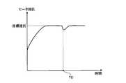
図16ないし図19は、切開検知方法の変形例1を示す図である。具体的に、図16及び図17では、第1の層41が切開された場合のヒータ抵抗及び投入電力の挙動をそれぞれ示している。また、図18及び図19では、第1の層41が切開されなかった場合のヒータ抵抗及び投入電力の挙動をそれぞれ示している。
ヒータ20(電気抵抗パターン)への投入電力は、図17または図19に示すように、ヒータ抵抗を目標抵抗に到達させる制御により、ピークを1つ持つ挙動となる。16 to 19 are views showing a
As shown in FIGS. 17 or 19, the power input to the heater 20 (electrical resistance pattern) has a behavior of having one peak by controlling the heater resistance to reach the target resistance.
ここで、図16及び図17と図18及び図19とを比較して分かるように、時間TC(図16,図17)において第1の層41が切開された場合には、ヒータ抵抗及び投入電力の挙動に不連続な変化が起こる。
具体的に、第1の層41が切開された場合には、第2の層42によってジョー本体71とブレード19とは熱的に接続される。そして、ブレード19の熱が第2の層42を経由することによってジョー本体71に奪われるため、ブレード19の温度低下をもたらす。当該ブレード19の温度低下は、ヒータ20の温度低下をもたらし、すなわち、ヒータ抵抗の低下をもたらす。当該ヒータ抵抗を目標抵抗に維持しようとすると、投入電力を増加させることになり、時刻TC以降、一時的に、投入電力が増加する。以上のことから、時刻TCにおいて、ヒータ抵抗及び投入電力の挙動に不連続な変化が起こる。
そして、プロセッサ15は、ステップS9において、ヒータ抵抗及び投入電力の挙動に不連続な変化が起こった場合には、第1の層41の切開が完了したと判定する。すなわち、当該ヒータ抵抗及び当該投入電力は、本発明に係る「検査部材の処置状態を示す指標値」に相当する。Here, as can be seen by comparing FIGS. 16 and 17 with FIGS. 18 and 19, when the
Specifically, when the
Then, when the behavior of the heater resistance and the input power changes discontinuously in step S9, the
また、例えば、上述した実施の形態1~3において、対象部位に対して超音波エネルギのみを付与することによって当該対象部位を処置する構成を採用しても構わない。この際、ステップS9において第1の層41の切開が完了したか否かを判定する切開検知方法としては、以下の方法を例示することができる。
図20は、切開検知方法の変形例2を示す図である。具体的に、図20は、超音波インピーダンスの挙動を示す図である。当該超音波インピーダンスは、超音波エネルギ出力部10から超音波振動子82に対して供給されている交流電力の電圧値及び電流値に基づいて算出されるインピーダンス値である。
ここで、処置部91から超音波振動が付与されることによって第1の層41が徐々に薄くなっていくと、振動伝達部材9への応力増加によって、超音波インピーダンスは、図20に示すように、増加していく。そして、第1の層41が切開されると、ジョー7と振動伝達部材9とが接触し、超音波振動によってパッド72が溶けはじめると、超音波インピーダンスは、下がる。
そして、プロセッサ15は、ステップS9において、超音波インピーダンスが上述した挙動となった場合に、第1の層41の切開が完了したと判定する。すなわち、当該超音波インピーダンスは、本発明に係る「検査部材の処置状態を示す指標値」に相当する。Further, for example, in the above-described first to third embodiments, a configuration may be adopted in which the target portion is treated by applying only ultrasonic energy to the target portion. At this time, the following method can be exemplified as an incision detection method for determining whether or not the incision of the
FIG. 20 is a diagram showing a
Here, when the
Then, in step S9, the
1,1C 処置システム
2,2C 処置具
3,3C ジェネレータ
4 検査シート
5 保持ケース
6 シース
7 ジョー(第1のジョー)
8 振動子ユニット
9 振動伝達部材
10 超音波エネルギ出力部
11 高周波エネルギ出力部
12 電圧検出部
13 電流検出部
14 検出回路
15 プロセッサ
16 第1のメモリ
17 報知部
18 第2のジョー
19 ブレード
20 ヒータ
21 熱エネルギ出力部
41 第1の層
42 第2の層
51 保持ケース本体
52 固定ハンドル
53 可動ハンドル
54 スイッチ
55 第2のメモリ
71 ジョー本体
72 パッド
81 振動子ケース
82 超音波振動子
91 処置部
Ar1 先端側
Ar2 基端側
Ax 中心軸
C 電気ケーブル
C1,C1´ 第1の電流経路
C2,C2´ 第2の電流経路
C3,C3´ 第3の電流経路
CL0,CL0´,CL1~CL4 曲線
P0~P5 点
T1 時間
TA1 処置時振動振幅
TA2 処置時温度
TC 時間
TH1 基準完了時間
TH2 基準振幅
TH3 基準温度1,
8
Claims (8)
Translated fromJapaneseジェネレータと、を備え、
前記処置具は、
前記処置エネルギを前記生体組織に対して付与する第1の把持部材と、
前記第1の把持部材との間で前記生体組織を把持する第2の把持部材と、を有し、
前記ジェネレータは、
前記処置具に対して前記電力を供給する電源回路と、
前記第1の把持部材及び前記第2の把持部材の間に把持され、前記第1の把持部材から前記処置エネルギが付与された検査部材の処置状態を示す指標値を検出する検出回路と、
前記指標値に基づいて、前記検査部材に対する前記処置エネルギの付与が開始されてから前記検査部材における特定の処置が完了するまでの処置完了時間を測定するプロセッサと、を有し、
前記処置具及び前記ジェネレータの少なくとも一方は、
前記検査部材の特性を示すデータであって、前記検査部材に対して付与される前記処置エネルギの強度と前記処置完了時間との関係を示す特性データを記憶する第1のメモリをさらに有し、
前記プロセッサは、
測定した前記処置完了時間と、前記検査部材に対して付与した前記処置エネルギの強度と、前記特性データとに基づいて、前記生体組織を処置する際の前記処置エネルギの強度に関する制御パラメータを算出する処置システム。A treatment tool that applies treatment energy generated according to the supplied electric power to living tissue, and
With a generator,
The treatment tool
A first gripping member that applies the treatment energy to the living tissue,
It has a second gripping member that grips the living tissue between the first gripping member and the living tissue.
The generator
A power supply circuit that supplies the power to the treatment tool,
A detection circuit that detects an index value indicating a treatment state of an inspection member gripped between the first gripping member and the second gripping member and to which the treatment energy is applied from the first gripping member.
Based on the index value, the processor has a processor that measures the treatment completion time from the start of applying the treatment energy to the inspection member to the completion of a specific treatment in the inspection member.
At least one of the treatment tool and the generator
It further has a first memory for storing characteristic data showing the characteristics of the inspection member and showing the relationship between the intensity of the treatment energy applied to the inspection member and the treatment completion time.
The processor
Based on the measured treatment completion time, the intensity of the treatment energy applied to the inspection member, and the characteristic data, control parameters relating to the intensity of the treatment energy when treating the biological tissue are calculated. Treatment system.
第1の強度の前記処置エネルギを前記検査部材に対して付与した際の前記処置完了時間である第1の処置完了時間と、前記第1の強度とは異なる第2の強度の前記処置エネルギを前記検査部材に対して付与した際の前記処置完了時間である第2の処置完了時間とをそれぞれ測定し、
前記第1の処置完了時間と、前記第2の処置完了時間と、前記第1の強度と、前記第2の強度と、前記特性データとに基づいて、前記制御パラメータを算出する、請求項1に記載の処置システム。The processor
The first treatment completion time, which is the treatment completion time when the treatment energy of the first intensity is applied to the inspection member, and the treatment energy of the second intensity different from the first intensity are combined. The second treatment completion time, which is the treatment completion time when applied to the inspection member, was measured, respectively.
1. The control parameter is calculated based on the first treatment completion time, the second treatment completion time, the first intensity, the second intensity, and the characteristic data. The treatment system described in.
前記第1の把持部材と前記第2の把持部材とによる互いに異なる複数の把持力にそれぞれ対応した複数の前記特性データを記憶し、
前記プロセッサは、
前記第1の処置完了時間と、前記第2の処置完了時間と、前記第1の強度と、前記第2の強度と、前記複数の特性データとに基づいて、前記制御パラメータを算出する、請求項2に記載の処置システム。The first memory is
A plurality of the characteristic data corresponding to a plurality of different gripping forces by the first gripping member and the second gripping member are stored.
The processor
A claim for calculating the control parameter based on the first treatment completion time, the second treatment completion time, the first intensity, the second intensity, and the plurality of characteristic data. Item 2. The treatment system according to item 2.
前記第1の処置完了時間と、前記第2の処置完了時間と、前記第1の強度と、前記第2の強度とに基づいて、前記特性データを補正し、
前記第1の処置完了時間と、前記第2の処置完了時間と、前記第1の強度と、前記第2の強度と、補正後の前記特性データとに基づいて、前記制御パラメータを算出する、請求項2に記載の処置システム。The processor
The characteristic data is corrected based on the first treatment completion time, the second treatment completion time, the first intensity, and the second intensity.
The control parameter is calculated based on the first treatment completion time, the second treatment completion time, the first intensity, the second intensity, and the corrected characteristic data. The treatment system according to claim 2.
供給された前記電力に応じて前記処置エネルギである超音波振動を発生する超音波振動子を備え、
前記第1の把持部材は、
前記超音波振動を前記生体組織に対して伝達する振動伝達部材を備え、
前記特性データは、
前記超音波振動の振動振幅に関する超音波パラメータと前記処置完了時間との関係を示すデータであり、
前記制御パラメータは、
前記生体組織を処置する際の前記超音波パラメータである、請求項1に記載の処置システム。The treatment tool
It is provided with an ultrasonic vibrator that generates ultrasonic vibration, which is the treatment energy, according to the supplied electric power.
The first gripping member is
A vibration transmission member that transmits the ultrasonic vibration to the living tissue is provided.
The characteristic data is
Data showing the relationship between the ultrasonic parameters related to the vibration amplitude of the ultrasonic vibration and the treatment completion time.
The control parameters are
The treatment system according to claim 1, which is the ultrasonic parameter for treating the living tissue.
供給された前記電力に応じて前記処置エネルギである熱を発生するヒータと、
前記ヒータに発生した熱を前記生体組織に対して伝達するブレードとを備え、
前記特性データは、
前記ブレードの温度に関する温度パラメータと前記処置完了時間との関係を示すデータであり、
前記制御パラメータは、
前記生体組織を処置する際の前記温度パラメータである、請求項1に記載の処置システム。The first gripping member is
A heater that generates heat, which is the treatment energy, according to the supplied electric power.
It is provided with a blade that transfers the heat generated in the heater to the living tissue.
The characteristic data is
It is data which shows the relationship between the temperature parameter about the temperature of the blade and the treatment completion time.
The control parameters are
The treatment system according to claim 1, which is the temperature parameter when treating the living tissue.
前記制御パラメータの算出履歴を示す履歴情報を記憶する第2のメモリをさらに有し、
前記プロセッサは、
前記制御パラメータを算出した後、前記第2のメモリの前記履歴情報を更新する、請求項1に記載の処置システム。The treatment tool
It further has a second memory for storing history information indicating the calculation history of the control parameter.
The processor
The treatment system according to claim 1, wherein after calculating the control parameters, the history information in the second memory is updated.
第1の把持部材及び第2の把持部材の間に把持され前記第1の把持部材から処置エネルギが付与された検査部材の処置状態を示す指標値に基づいて、前記検査部材に対する前記処置エネルギの付与が開始されてから前記検査部材における特定の処置が完了するまでの処置完了時間を測定し、
測定した前記処置完了時間と、前記検査部材に対して付与した前記処置エネルギの強度と、前記検査部材の特性を示すデータであって、前記検査部材に対して付与される前記処置エネルギの強度と前記処置完了時間との関係を示す特性データとに基づいて、生体組織を処置する際の前記処置エネルギの強度に関する制御パラメータを算出する制御パラメータ算出方法。It is a control parameter calculation method executed by the processor of the generator.
The treatment energy for the inspection member is based on an index value indicating the treatment state of the inspection member gripped between the first grip member and the second grip member and the treatment energy is applied from the first grip member. The treatment completion time from the start of granting to the completion of a specific treatment on the inspection member is measured.
The measured treatment completion time, the intensity of the treatment energy applied to the inspection member, and the data showing the characteristics of the inspection member, the intensity of the treatment energy applied to the inspection member. A control parameter calculation method for calculating a control parameter relating to the intensity of the treatment energy when treating a living tissue based on characteristic data showing a relationship with the treatment completion time.
Priority Applications (2)
| Application Number | Priority Date | Filing Date | Title |
|---|---|---|---|
| PCT/JP2020/003279WO2021152752A1 (en) | 2020-01-29 | 2020-01-29 | Treatment system and control parameter calculation method |
| US17/852,911US12440259B2 (en) | 2022-06-29 | Treatment system and control parameter calculation method |
Applications Claiming Priority (1)
| Application Number | Priority Date | Filing Date | Title |
|---|---|---|---|
| PCT/JP2020/003279WO2021152752A1 (en) | 2020-01-29 | 2020-01-29 | Treatment system and control parameter calculation method |
Related Child Applications (1)
| Application Number | Title | Priority Date | Filing Date |
|---|---|---|---|
| US17/852,911ContinuationUS12440259B2 (en) | 2022-06-29 | Treatment system and control parameter calculation method |
Publications (1)
| Publication Number | Publication Date |
|---|---|
| WO2021152752A1true WO2021152752A1 (en) | 2021-08-05 |
Family
ID=77078792
Family Applications (1)
| Application Number | Title | Priority Date | Filing Date |
|---|---|---|---|
| PCT/JP2020/003279CeasedWO2021152752A1 (en) | 2020-01-29 | 2020-01-29 | Treatment system and control parameter calculation method |
Country Status (1)
| Country | Link |
|---|---|
| WO (1) | WO2021152752A1 (en) |
Citations (1)
| Publication number | Priority date | Publication date | Assignee | Title |
|---|---|---|---|---|
| WO2018047352A1 (en)* | 2016-09-12 | 2018-03-15 | オリンパス株式会社 | Energy control device and treatment system |
- 2020
- 2020-01-29WOPCT/JP2020/003279patent/WO2021152752A1/ennot_activeCeased
Patent Citations (1)
| Publication number | Priority date | Publication date | Assignee | Title |
|---|---|---|---|---|
| WO2018047352A1 (en)* | 2016-09-12 | 2018-03-15 | オリンパス株式会社 | Energy control device and treatment system |
Also Published As
| Publication number | Publication date |
|---|---|
| US20220323136A1 (en) | 2022-10-13 |
Similar Documents
| Publication | Publication Date | Title |
|---|---|---|
| US9808305B2 (en) | Energy treatment apparatus | |
| US10194972B2 (en) | Managing tissue treatment | |
| JP4734058B2 (en) | Medical treatment device | |
| EP3397182B1 (en) | Surgical instrument with staged application of electrosurgical and ultrasonic energy | |
| JP5259883B2 (en) | High frequency surgical device and surgical device | |
| CN105451677B (en) | Biological tissue joining system | |
| JP5031395B2 (en) | Energy-based treatment system and method | |
| JP5911650B2 (en) | Grasping treatment device | |
| US9597106B2 (en) | Ultrasonic treatment apparatus | |
| JP2016537129A (en) | Ultrasonic surgical instrument with electrosurgical features | |
| CN102497827A (en) | Electrosurgery generator for ultrasonic surgical instruments | |
| US20150196782A1 (en) | Ultrasonic probe and ultrasonic treatment device | |
| WO2021152752A1 (en) | Treatment system and control parameter calculation method | |
| JP6665300B2 (en) | Energy control device, treatment system, and method of operating energy control device | |
| US12440259B2 (en) | Treatment system and control parameter calculation method | |
| US10314636B2 (en) | Treatment apparatus and method for controlling the same | |
| JP2021030092A (en) | Ultrasonic system and method with tissue resistance sensing | |
| WO2023007548A1 (en) | Energy treatment system | |
| US20210000530A1 (en) | Cordless surgical device and control method | |
| WO2022049644A1 (en) | Treatment tool and treatment system | |
| WO2017149765A1 (en) | Energy control device and energy treatment tool |
Legal Events
| Date | Code | Title | Description |
|---|---|---|---|
| 121 | Ep: the epo has been informed by wipo that ep was designated in this application | Ref document number:20916652 Country of ref document:EP Kind code of ref document:A1 | |
| NENP | Non-entry into the national phase | Ref country code:DE | |
| 122 | Ep: pct application non-entry in european phase | Ref document number:20916652 Country of ref document:EP Kind code of ref document:A1 | |
| NENP | Non-entry into the national phase | Ref country code:JP |