WO2021143622A1 - Tissue clipping device and use method therefor - Google Patents
Tissue clipping device and use method thereforDownload PDFInfo
- Publication number
- WO2021143622A1 WO2021143622A1PCT/CN2021/070878CN2021070878WWO2021143622A1WO 2021143622 A1WO2021143622 A1WO 2021143622A1CN 2021070878 WCN2021070878 WCN 2021070878WWO 2021143622 A1WO2021143622 A1WO 2021143622A1
- Authority
- WO
- WIPO (PCT)
- Prior art keywords
- clip
- tube
- sleeve
- seat
- outer tube
- Prior art date
- Legal status (The legal status is an assumption and is not a legal conclusion. Google has not performed a legal analysis and makes no representation as to the accuracy of the status listed.)
- Ceased
Links
Images


Classifications
- A—HUMAN NECESSITIES
- A61—MEDICAL OR VETERINARY SCIENCE; HYGIENE
- A61B—DIAGNOSIS; SURGERY; IDENTIFICATION
- A61B17/00—Surgical instruments, devices or methods
- A61B17/12—Surgical instruments, devices or methods for ligaturing or otherwise compressing tubular parts of the body, e.g. blood vessels or umbilical cord
- A61B17/128—Surgical instruments, devices or methods for ligaturing or otherwise compressing tubular parts of the body, e.g. blood vessels or umbilical cord for applying or removing clamps or clips
- A61B17/1285—Surgical instruments, devices or methods for ligaturing or otherwise compressing tubular parts of the body, e.g. blood vessels or umbilical cord for applying or removing clamps or clips for minimally invasive surgery
- A—HUMAN NECESSITIES
- A61—MEDICAL OR VETERINARY SCIENCE; HYGIENE
- A61F—FILTERS IMPLANTABLE INTO BLOOD VESSELS; PROSTHESES; DEVICES PROVIDING PATENCY TO, OR PREVENTING COLLAPSING OF, TUBULAR STRUCTURES OF THE BODY, e.g. STENTS; ORTHOPAEDIC, NURSING OR CONTRACEPTIVE DEVICES; FOMENTATION; TREATMENT OR PROTECTION OF EYES OR EARS; BANDAGES, DRESSINGS OR ABSORBENT PADS; FIRST-AID KITS
- A61F2/00—Filters implantable into blood vessels; Prostheses, i.e. artificial substitutes or replacements for parts of the body; Appliances for connecting them with the body; Devices providing patency to, or preventing collapsing of, tubular structures of the body, e.g. stents
- A61F2/02—Prostheses implantable into the body
- A61F2/24—Heart valves ; Vascular valves, e.g. venous valves; Heart implants, e.g. passive devices for improving the function of the native valve or the heart muscle; Transmyocardial revascularisation [TMR] devices; Valves implantable in the body
- A61F2/2442—Annuloplasty rings or inserts for correcting the valve shape; Implants for improving the function of a native heart valve
- A61F2/246—Devices for obstructing a leak through a native valve in a closed condition
- A—HUMAN NECESSITIES
- A61—MEDICAL OR VETERINARY SCIENCE; HYGIENE
- A61B—DIAGNOSIS; SURGERY; IDENTIFICATION
- A61B17/00—Surgical instruments, devices or methods
- A61B17/12—Surgical instruments, devices or methods for ligaturing or otherwise compressing tubular parts of the body, e.g. blood vessels or umbilical cord
- A61B17/122—Clamps or clips, e.g. for the umbilical cord
- A—HUMAN NECESSITIES
- A61—MEDICAL OR VETERINARY SCIENCE; HYGIENE
- A61F—FILTERS IMPLANTABLE INTO BLOOD VESSELS; PROSTHESES; DEVICES PROVIDING PATENCY TO, OR PREVENTING COLLAPSING OF, TUBULAR STRUCTURES OF THE BODY, e.g. STENTS; ORTHOPAEDIC, NURSING OR CONTRACEPTIVE DEVICES; FOMENTATION; TREATMENT OR PROTECTION OF EYES OR EARS; BANDAGES, DRESSINGS OR ABSORBENT PADS; FIRST-AID KITS
- A61F2/00—Filters implantable into blood vessels; Prostheses, i.e. artificial substitutes or replacements for parts of the body; Appliances for connecting them with the body; Devices providing patency to, or preventing collapsing of, tubular structures of the body, e.g. stents
- A61F2/02—Prostheses implantable into the body
- A61F2/24—Heart valves ; Vascular valves, e.g. venous valves; Heart implants, e.g. passive devices for improving the function of the native valve or the heart muscle; Transmyocardial revascularisation [TMR] devices; Valves implantable in the body
- A61F2/2442—Annuloplasty rings or inserts for correcting the valve shape; Implants for improving the function of a native heart valve
- A61F2/2466—Delivery devices therefor
Definitions
- the inventionbelongs to the technical field of medical devices, and specifically relates to a device for tissue clamping and a method of use thereof.
- Heart valvular diseaseis one of the most common heart diseases in my country, among which valve damage is mainly caused by rheumatic fever; in recent years, with the development of the aging population, valve degeneration (including calcification and mucous degeneration) and metabolic disorders valves Damage is also increasing in our country.
- the characteristic of mitral regurgitationis the retrograde flow of blood from the left ventricle of the heart to the left atrium through the malfunctioning mitral valve.
- the mitral valveacts as a check valve to prevent oxygenated blood from flowing back into the left atrium, so that oxygenated blood is pumped through the aortic valve to the aorta and then to the whole body.
- Mitral regurgitationcan significantly reduce the pumping efficiency of the heart, thereby putting the patient at severe and progressive risk of heart failure.
- the most common treatment of mitral regurgitationrelies on valve replacement or repair, including leaflet and annulus remodeling, the latter of which is generally called valvuloplasty. Although all these techniques are very effective, because they rely on thoracotomy, the surgical trauma is large and the patient recovers slowly.
- Abbott’s Mitraclipa valve clamping device through percutaneous venous intervention, has also appeared internationally, but its complicated operation has brought trouble to doctors.
- Patent documentssuch as the patent document with publication number CN107595435A disclose a valve clamp, including a first clamping part, a second clamping part, and a connecting part.
- the first clamping parthas at least two first clamping parts.
- the second clamping memberhas a corresponding number of second clamping arms, and each of the first clamping arms and its corresponding second clamping arm can be combined into a set of clamps, but its operation is not Convenient and unstable release, which affects the success rate of surgery.
- the present inventionprovides a device for tissue splicing and a method of use thereof.
- a device for tissue clampingincluding a handle, an inner tube, an inner clamp, an outer tube seat, an outer tube, a sleeve, an outer clamp, and a release mechanism; the front end of the outer tube is connected with the sleeve, and the rear end is connected with the outer tube Seat connection;
- the outer cliphas an outer clip seat and two open-shaped outer clips located on the outer clip seat, the outer clip seat is sleeved in the casing and the two outer clips leak out of one end of the casing mouth, So that the outer clamp seat can move in the casing along the direction of the sleeve, the outer clamp is driven by the sleeve mouth to clamp; the inner tube passes through the outer tube seat, the outer tube, the sleeve, and the outer clamp seat is sleeved in the outer tube in turn , The front end of the inner tube is connected with the inner clip, and the rear end is connected with the handle, so that the handle drives the inner tube and the inner clip to move in the outer tube along
- the inner clip piece and the outer clip pieceare combined to form a clamp when they are in conflict;
- the release mechanismis sleeved at the connection between the front end of the outer tube and the sleeve, and is used to lock or unlock the connection between the outer tube and the sleeve.
- the release mechanismincludes a release tube and a release tube seat, the front end of the release tube has an inner cavity and a boss, the sleeve is embedded in the inner cavity and the outer side is provided with a grooved convex wall, the belt The groove convex wall is matched with the boss to form a rotating clamping structure; one end of the release pipe seat is connected with the rear end of the release pipe for rotating the release pipe.
- the release tube socketis further provided with an emptying port for surgical emptying, the other end of the release tube socket is provided with a sealing element; the end of the outer tube socket is provided with a luer interface.
- the diameter of the inner tubeis 0.5-2.5 mm
- the diameter of the outer tubeis 2.6-5 mm
- the opening angle of the two outer clipsis 100-160 degrees.
- the diameter of the casing tubeis smaller than the diameter of the outer tube so that the casing can be inserted into the outer tube, and the outer tube has a limiting step inside, and the limiting step is used to abut the bottom of the casing.
- the front end of the outer tubefurther has a limiting groove
- the sleevehas a limiting protrusion
- the limiting groove and the limiting protrusionare matched to restrict the sleeve from moving in the circumferential direction of the outer tube.
- a number of holesare provided on the sleeve wall of the sleeve for accelerating endothelialization of the sleeve implantation.
- the abutting surface sides of the inner clip and the outer clipare respectively provided with clamping teeth, and the outer bottom end of the outer clip is also provided with a clamping protrusion.
- the end of the mouth of the inner cavity of the sleeveis provided with an internal thread
- the outer side of the outer clamp seatis provided with an external thread adapted to the internal thread
- a method for using a device for tissue clampingis implemented by a device for tissue clamping, and includes the following steps:
- the present inventionhas the following beneficial effects:
- the device for tissue clamping and its use method of the present inventioncan be operated more conveniently, accurately and safely, and the operation requirements for doctors are reduced. At the same time, if the clamping position of the mitral valve leaflets is not good, the clamping can be repeated, and then the operation is released.
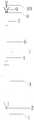
- Figure 1is a schematic diagram of the overall structure of the device for tissue clamping according to the first embodiment of the present invention
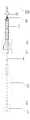
- FIG. 2is a schematic diagram of the overall cross-sectional structure of the device for tissue splicing according to the first embodiment of the present invention
- Fig. 3is a schematic diagram of the operating state of the device for tissue clamping according to the first embodiment of the present invention
- FIG. 4is a schematic diagram of the internal and external clamps of the device for tissue clamping according to the first embodiment of the present invention after being released;
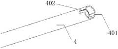
- Fig. 5is a schematic diagram of the outer tube structure of the device for tissue splicing according to the first embodiment of the present invention
- FIG. 6is a schematic diagram of a cross-sectional structure of the release tube of the device for tissue clamping according to the first embodiment of the present invention
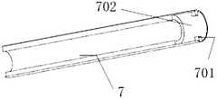
- Figure 7is a schematic diagram of the sleeve structure of the device for tissue clamping according to the first embodiment of the present invention.
- Fig. 8is a schematic structural view of the valve leaflets of the outer clamping part of the device for tissue clamping according to the first embodiment of the present invention
- FIG. 9is a schematic structural view of the valve leaflets of the inner clamping part of the device for tissue clamping according to the first embodiment of the present invention.
- a device system and method for tissue clamping of this embodimentincludes a handle 1, an inner tube 2, an outer tube seat 3, an outer tube 4, a release mechanism, and a sleeve 8 , Outer clip 9, inner clip 10.
- the front section of the inner tube 2is connected with the inner clip 10, and the rear end is connected with the handle 1.
- the front section of the outer tube 4is connected with the sleeve 8, and the rear end is connected with the outer tube socket 3.
- the inner cavity 702 of the front section of the release tube 7has a boss 701.
- the sleeve 8is fixed on the outer tube 4, and the release mechanism is released. Fall off from the outer tube 4.
- the front end of the outer tube 4is connected with the sleeve 8, and the rear end is connected with the outer tube base 3 by threaded connection or adhesive fixation.
- the diameter of the sleeve 8is smaller than the diameter of the outer tube 4 so that the sleeve 8 can be inserted into the outer tube.
- Tube 4the outer tube 4 has a limiting step 402 inside, the limiting step 402 abuts the bottom of the sleeve 8, the front end of the outer tube 4 also has a limiting groove 401, the sleeve 8 has a limiting protrusion 801, a limiting recess
- the groove 401is matched with the limiting protrusion 801 to restrict the sleeve 8 from moving in the circumferential direction of the outer tube 4;
- the outer clamp 9has an outer clamp seat 902 and two outer clamp pieces 901 which are open on the outer clamp seat 902,
- the clamp seat 902is sleeved in the sleeve 8 and the two outer clamp pieces 901 leak out from one end of the sleeve 8 port, so that the outer clamp seat 902 can move in the sleeve 8 along the direction of the sleeve 8 and is driven by the sleeve 8 port.
- the external clampis clamped, the end of the inner cavity of the sleeve 8 is provided with internal threads, and the outside of the outer clamp seat 902 is provided with external threads that match the internal threads.
- the outer clamp seat 902can be clamped first. Screw into the thread of the sleeve 8 to avoid arbitrary movement of the outer clamp seat 902.
- the outer bottom end of the outer clamp 901is also provided with a clamping protrusion.
- the clamping protrusionis clamped on the inner cavity port of the sleeve 8
- the inner tube 2penetrates through the outer tube socket 3, the outer tube 4, the sleeve 8, and the outer clamp seat 902 in sequence, and is sleeved in the outer tube 4, and the front end of the inner tube 2 is connected with the inner clamp seat 102 through threads.
- the rear end and the handle 1are connected by threaded connection or adhesive fixation, so that the handle 1 drives the inner tube 2 and the inner clip 10 to move in the outer tube 4 along the direction of the outer tube 4; the inner clip 10 has an inner clip seat 102 and two
- the inner clip 101is located on the inner clip seat 102 in an open shape.
- the inner clip seat 102has abutting protrusions so that when the inner clip seat 102 is in contact with the outer clip seat 902, the outer clip seat 902 is driven to move along the tube direction of the sleeve 8 ,
- the outer clamp seat 902is also provided with non-circular grooves such as square, triangle, special-shaped, etc., and the shape of the groove end is inserted into the groove against the front end of the protrusion to match the groove, so that the inner clamp seat 102 can also drive the outer clamp seat 902 rotates along the circumferential direction of the sleeve 8;
- the inner clip 101is adapted to the outer clip 901, so that the inner clip 101 and the outer clip 901 are combined to form a fixture when the inner clip 101 and the outer clip 901 collide, and the inner clip 101 and the outer clip 901 are both It is arc-shaped, and the side of the contact surface is respectively provided with barbed gripping teeth to strengthen the clamping force;
- the release mechanismis sleeved at
- the front end of the release tube 7has an inner cavity 702 and a boss 701.
- the sleeve 8is embedded in the inner cavity 702 and the outer side is provided with a grooved convex wall 802 with grooves.
- the convex wall 802is adapted to the boss 701 to form a rotary clamping structure. Specifically, the boss 701 can pass through the groove of the grooved convex wall 802 and rotate and move at the concave wall to be clamped at the convex wall.
- the release pipe socket 6is connected with the rear end of the release pipe 7 by screwing or glueing, and is used to hold the rotating release pipe socket 6 Drive the release tube 7 to rotate; the release tube seat 6 is also provided with an emptying port for surgical discharge
- the other end of the release tube socket 6is provided with a sealing element.
- the sealing elementcan be a sealing screw, a gasket, etc., which can enhance the drainage and sealing performance.
- the release mechanismcan also be two semicircular clamps sandwiching each other.
- the bottom end of the sheetcan be opened to release and unlock the connection between the sleeve 8 and the outer tube 4, or the sleeve 8 has an L-shaped groove, and the release tube 7 has a protrusion that is adapted to the L-shaped groove to complete the locking or unlocking, etc.
- the specific structure of the release mechanismis not limited; the end of the outer tube base 3 is designed with a standard Luer interface thread, which can be easily connected to standard Luer interface devices and enhance functionality.
- the handle 1can be made of polymer materials such as PP, ABS, and metal materials.
- the structureis not limited and easy to operate; the diameter of the inner tube 2 is preferably 0.5-2.5mm, and the material of the outer tube 4 is selected for use in surgical operations.
- High polymer materialssuch as PP, ABS, PE, etc.
- metal materialssuch as stainless steel, nickel-titanium, etc., with a diameter of 2.6-5mm.
- the front end and the inner clamp 10are connected by threads, the rear end and the handle 1 can be fixed with positive and negative threads, holes are inserted with rivets, and can be disassembled on site;
- the outer tube base 3is made of polymer materials, such as PP, ABS, etc., and the release tube is sealed
- the part 5selects the sealing screw and the release tube base 6 as an integrated device, the material is polymer material, metal material, and the sealing gasket is added under the sealing screw, and the release tube 7 is made of polymer material and metal material, such as PP, ABS, PE and Stainless steel, etc.
- the casing 8is made of polymer materials, metal materials or alloy materials.
- the limiting protrusion 801 of the casing 8can be one or more, preferably 2-3, corresponding to the limit of the adapting casing 8.
- the number of grooves 401, the position of the limiting protrusion 801 and the limiting groove 401can be interchanged, the length of the sleeve 8 inserted into the outer tube 4 is preferably 1-3mm, and the sleeve 8 with grooves and convex walls 802 is the outer ring
- the outer ringis 0.5-2mm wide, the number of grooves is preferably 2-3, and the number of bosses 701 of the release tube 7 is adapted to the number of holes 803 on the wall of the sleeve 8 to accelerate the endothelialization process after implantation in the human body;
- the outer clip 9is made of nickel-titanium material, and the two clips are arc-shaped.
- the angle of the two clipsreaches 100-160 degrees, which is convenient for capturing the mitral valve leaflets;
- the inner clip 10is made of nickel-titanium material, two
- the clip pieceis arc-shaped and matches the outer clip 9.
- a method of using a device for tissue clampingincludes the following steps:
- Send the device for tissue clamping to the heart valvefor example, send the device from the apex of the heart to the ventricular valve by surgery, control the inner tube 2 to move back and forth through the handle 1, and adjust the position of the inner clip 10 to make the outer
- the position of the clip 901 and the inner clip 101are respectively located on the inner and outer sides of the prolapsed valve leaflet;
- the embodiments of the present inventionare described in terms of repairing mitral valve regurgitation. Those skilled in the art can understand that the repairing mitral valve regurgitation disclosed in the present invention can also be used for other devices or to deliver other devices. To the corresponding position of the body. The present invention is not limited to one method for repairing mitral valve regurgitation.
Landscapes
- Health & Medical Sciences (AREA)
- Cardiology (AREA)
- Life Sciences & Earth Sciences (AREA)
- General Health & Medical Sciences (AREA)
- Veterinary Medicine (AREA)
- Biomedical Technology (AREA)
- Heart & Thoracic Surgery (AREA)
- Vascular Medicine (AREA)
- Engineering & Computer Science (AREA)
- Animal Behavior & Ethology (AREA)
- Public Health (AREA)
- Surgery (AREA)
- Transplantation (AREA)
- Oral & Maxillofacial Surgery (AREA)
- Reproductive Health (AREA)
- Nuclear Medicine, Radiotherapy & Molecular Imaging (AREA)
- Medical Informatics (AREA)
- Molecular Biology (AREA)
- Surgical Instruments (AREA)
- Prostheses (AREA)
Abstract
Description
Translated fromChinese本发明属于医疗器械技术领域,具体涉及一种用于组织夹合的装置及其使用方法。The invention belongs to the technical field of medical devices, and specifically relates to a device for tissue clamping and a method of use thereof.
心脏瓣膜病是我国最常见的心脏病之一,其中主要为风湿热导致的瓣膜损害;近年来随着人口老龄化的发展,瓣膜退行性变(包括钙化和粘液变性等)以及代谢障碍性瓣膜损害在我国也日益增多。二尖瓣反流的特征是血液通过机能不健全的二尖瓣从心脏的左心室到左心房的逆行流动。在正常的心脏收缩周期期间,二尖瓣作为止回阀,防止含氧血液回流进左心房,如此,含氧血液通过主动脉瓣泵送到主动脉,然后至全身。二尖瓣反流会显著降低心脏的泵送效率,从而将患者置于严重的、渐进的心脏衰竭风险。最常见的二尖瓣反流治疗依赖瓣膜置换或修复,包括瓣叶和环重塑,后者一般称为瓣膜成形术。尽管所有这些技术非常有效,但因为其依赖开胸,手术创伤大,患者恢复慢。近年来,国际上也出现了雅培公司的Mitraclip,一种通过经皮静脉介入的瓣膜钳夹装置,但其复杂的操作给医生带来了困扰。专利文献如公开号为CN107595435A的专利文献公开了一种瓣膜夹合器,包括第一夹合部件、第二夹合部件和连接部,所述第一夹合部件具有至少两个第一夹合臂,所述第二夹合部件具有相应数量的第二夹合臂,每个所述第一夹合臂同其相应的所述第二夹合臂可组合成为一组夹具,但其操作不便捷,释放不稳定,影响手术成功率。Heart valvular disease is one of the most common heart diseases in my country, among which valve damage is mainly caused by rheumatic fever; in recent years, with the development of the aging population, valve degeneration (including calcification and mucous degeneration) and metabolic disorders valves Damage is also increasing in our country. The characteristic of mitral regurgitation is the retrograde flow of blood from the left ventricle of the heart to the left atrium through the malfunctioning mitral valve. During the normal systolic cycle, the mitral valve acts as a check valve to prevent oxygenated blood from flowing back into the left atrium, so that oxygenated blood is pumped through the aortic valve to the aorta and then to the whole body. Mitral regurgitation can significantly reduce the pumping efficiency of the heart, thereby putting the patient at severe and progressive risk of heart failure. The most common treatment of mitral regurgitation relies on valve replacement or repair, including leaflet and annulus remodeling, the latter of which is generally called valvuloplasty. Although all these techniques are very effective, because they rely on thoracotomy, the surgical trauma is large and the patient recovers slowly. In recent years, Abbott’s Mitraclip, a valve clamping device through percutaneous venous intervention, has also appeared internationally, but its complicated operation has brought trouble to doctors. Patent documents such as the patent document with publication number CN107595435A disclose a valve clamp, including a first clamping part, a second clamping part, and a connecting part. The first clamping part has at least two first clamping parts. The second clamping member has a corresponding number of second clamping arms, and each of the first clamping arms and its corresponding second clamping arm can be combined into a set of clamps, but its operation is not Convenient and unstable release, which affects the success rate of surgery.
针对现有相关技术的上述缺点,需要一种新的装置系统和方法。In view of the above-mentioned shortcomings of the existing related technologies, a new device system and method is needed.
发明内容Summary of the invention
基于现有技术中存在的上述不足,本发明提供一种用于组织夹合的装置及 其使用方法。Based on the above-mentioned shortcomings in the prior art, the present invention provides a device for tissue splicing and a method of use thereof.
为了达到上述发明目的,本发明采用以下技术方案:In order to achieve the above-mentioned purpose of the invention, the present invention adopts the following technical solutions:
一种用于组织夹合的装置,包括手柄、内管、内夹、外管座、外管、套管、外夹、释放机构;所述外管前端与套管连接,后端与外管座连接;所述外夹具有外夹座及两片位于外夹座上呈开口状的外夹片,所述外夹座套设于套管内且两片外夹片漏出于套管口一端,以使外夹座可以在套管内沿套管方向活动,由套管口带动外夹片夹合;所述内管依次贯穿外管座、外管、套管、外夹座套设于外管内,所述内管前端与内夹连接,后端与手柄连接,以使手柄依次带动内管、内夹沿外管方向在外管内活动;所述内夹具有内夹座及两片位于内夹座上呈开口状的内夹片,所述内夹座具有抵靠凸起,以使内夹座抵触外夹座时带动外夹座活动,所述内夹片与外夹片相适配,以使内夹片与外夹片抵触时组合为夹具;所述释放机构套设于外管前端与套管连接处,用于锁定或解锁外管与套管的连接。A device for tissue clamping, including a handle, an inner tube, an inner clamp, an outer tube seat, an outer tube, a sleeve, an outer clamp, and a release mechanism; the front end of the outer tube is connected with the sleeve, and the rear end is connected with the outer tube Seat connection; the outer clip has an outer clip seat and two open-shaped outer clips located on the outer clip seat, the outer clip seat is sleeved in the casing and the two outer clips leak out of one end of the casing mouth, So that the outer clamp seat can move in the casing along the direction of the sleeve, the outer clamp is driven by the sleeve mouth to clamp; the inner tube passes through the outer tube seat, the outer tube, the sleeve, and the outer clamp seat is sleeved in the outer tube in turn , The front end of the inner tube is connected with the inner clip, and the rear end is connected with the handle, so that the handle drives the inner tube and the inner clip to move in the outer tube along the direction of the outer tube in turn; the inner clip has an inner clip seat and two pieces located on the inner clip seat The upper is an open-shaped inner clip, the inner clip seat has abutting protrusions, so that when the inner clip seat is in contact with the outer clip seat, the outer clip seat is driven to move, and the inner clip is matched with the outer clip. The inner clip piece and the outer clip piece are combined to form a clamp when they are in conflict; the release mechanism is sleeved at the connection between the front end of the outer tube and the sleeve, and is used to lock or unlock the connection between the outer tube and the sleeve.
作为优选方案,所述释放机构包括释放管、释放管座,所述释放管前端具有内腔和凸台,所述套管嵌设于内腔且外侧设有带凹槽凸壁,所述带凹槽凸壁与凸台相适配以形成旋转卡接结构;所述释放管座一端与释放管后端连接,用于旋转释放管。As a preferred solution, the release mechanism includes a release tube and a release tube seat, the front end of the release tube has an inner cavity and a boss, the sleeve is embedded in the inner cavity and the outer side is provided with a grooved convex wall, the belt The groove convex wall is matched with the boss to form a rotating clamping structure; one end of the release pipe seat is connected with the rear end of the release pipe for rotating the release pipe.
作为优选方案,所述释放管座上还设有排空口,用于手术排空,所述释放管座另一端设有密封件;所述外管座尾端设有鲁尔接口。As a preferred solution, the release tube socket is further provided with an emptying port for surgical emptying, the other end of the release tube socket is provided with a sealing element; the end of the outer tube socket is provided with a luer interface.
作为优选方案,所述内管直径为0.5-2.5mm,所述外管直径为2.6-5mm,所述两片外夹片开口角度为100-160度。As a preferred solution, the diameter of the inner tube is 0.5-2.5 mm, the diameter of the outer tube is 2.6-5 mm, and the opening angle of the two outer clips is 100-160 degrees.
作为优选方案,所述套管管直径小于外管直径以使套管插接入外管,所述外管内部具有限位台阶,所述限位台阶用于抵靠套管底部。As a preferred solution, the diameter of the casing tube is smaller than the diameter of the outer tube so that the casing can be inserted into the outer tube, and the outer tube has a limiting step inside, and the limiting step is used to abut the bottom of the casing.
作为优选方案,所述外管前端还具有限位凹槽,所述套管具有限位凸起,所述限位凹槽与限位凸起相适配限制套管沿外管周向活动。As a preferred solution, the front end of the outer tube further has a limiting groove, the sleeve has a limiting protrusion, and the limiting groove and the limiting protrusion are matched to restrict the sleeve from moving in the circumferential direction of the outer tube.
作为优选方案,所述套管的套管壁上设有若干孔洞,用于加速套管植入内 皮化。As a preferred solution, a number of holes are provided on the sleeve wall of the sleeve for accelerating endothelialization of the sleeve implantation.
作为优选方案,所述内夹片和外夹片抵触面侧分别设有夹齿,所述外夹片外侧底端还设有卡接凸起。As a preferred solution, the abutting surface sides of the inner clip and the outer clip are respectively provided with clamping teeth, and the outer bottom end of the outer clip is also provided with a clamping protrusion.
作为优选方案,所述套管内腔管口端部设有内螺纹,所述外夹座外侧设有与内螺纹相适配的外螺纹。As a preferred solution, the end of the mouth of the inner cavity of the sleeve is provided with an internal thread, and the outer side of the outer clamp seat is provided with an external thread adapted to the internal thread.
一种用于组织夹合的装置使用方法,通过一种用于组织夹合的装置实现,包括如下步骤:A method for using a device for tissue clamping is implemented by a device for tissue clamping, and includes the following steps:
S1.将用于组织夹合的装置送至心脏瓣膜处,通过手柄控制内管前后移动,调节内夹的位置,使外夹片和内夹片位置分别位于脱垂的瓣叶内外两侧;S1. Send the device for tissue clamping to the heart valve, control the inner tube to move back and forth through the handle, and adjust the position of the inner clip so that the positions of the outer clip and the inner clip are located on the inner and outer sides of the prolapsed valve leaflet;
S2.抽动手柄将内夹和外夹收入到套管内,夹合瓣膜;S2. Twitch the handle to collect the inner clip and the outer clip into the sleeve and clamp the valve;
S3.解开内管和内夹的连接,调整释放机构,解锁外管与套管的连接,释放套管及内外夹。S3. Unlock the connection between the inner tube and the inner clamp, adjust the release mechanism, unlock the connection between the outer tube and the sleeve, and release the sleeve and the inner and outer clamps.
本发明与现有技术相比,有益效果是:Compared with the prior art, the present invention has the following beneficial effects:
本发明的一种用于组织夹合的装置及其使用方法能更加方便准确和安全地进行操作,降低了对医者的操作要求。同时,如果二尖瓣瓣叶夹合位置不佳时,可重复夹合,再操作释放。The device for tissue clamping and its use method of the present invention can be operated more conveniently, accurately and safely, and the operation requirements for doctors are reduced. At the same time, if the clamping position of the mitral valve leaflets is not good, the clamping can be repeated, and then the operation is released.
图1是本发明实施例一的用于组织夹合的装置的整体结构示意图;Figure 1 is a schematic diagram of the overall structure of the device for tissue clamping according to the first embodiment of the present invention;
图2是本发明实施例一的用于组织夹合的装置的整体剖面结构示意;2 is a schematic diagram of the overall cross-sectional structure of the device for tissue splicing according to the first embodiment of the present invention;
图3是本发明实施例一的用于组织夹合的装置的手术中使用状态示意图;Fig. 3 is a schematic diagram of the operating state of the device for tissue clamping according to the first embodiment of the present invention;
图4是本发明实施例一的用于组织夹合的装置的内外夹释放后示意图;4 is a schematic diagram of the internal and external clamps of the device for tissue clamping according to the first embodiment of the present invention after being released;
图5是本发明实施例一的用于组织夹合的装置的外管结构示意图;Fig. 5 is a schematic diagram of the outer tube structure of the device for tissue splicing according to the first embodiment of the present invention;
图6是本发明实施例一的用于组织夹合的装置的释放管剖面结构示意图;6 is a schematic diagram of a cross-sectional structure of the release tube of the device for tissue clamping according to the first embodiment of the present invention;
图7是本发明实施例一的用于组织夹合的装置的套管结构示意图;Figure 7 is a schematic diagram of the sleeve structure of the device for tissue clamping according to the first embodiment of the present invention;
图8是本发明实施例一的用于组织夹合的装置的外夹部分瓣叶闭合时结 构示意图;Fig. 8 is a schematic structural view of the valve leaflets of the outer clamping part of the device for tissue clamping according to the first embodiment of the present invention;
图9是本发明实施例一的用于组织夹合的装置的内夹部分瓣叶闭合时结构示意图;9 is a schematic structural view of the valve leaflets of the inner clamping part of the device for tissue clamping according to the first embodiment of the present invention;
其中:1.手柄;2.内管;3.外管座;4.外管;401.限位凹槽;402.限位台阶;5.释放管密封件;6.释放管座;7.释放管;701.凸台;702.内腔;8.套管;801.限位凸起;802.带凹槽凸壁;803.孔洞;9.外夹;901.外夹片;902.外夹座;10.内夹;101.内夹片;102.内夹座。Among them: 1. Handle; 2. Inner tube; 3. Outer tube seat; 4. Outer tube; 401. Limit groove; 402. Limit step; 5. Release tube seal; 6. Release tube seat; 7. Release tube; 701. Boss; 702. Inner cavity; 8. Casing; 801. Limiting protrusion; 802. Convex wall with groove; 803. Hole; 9. Outer clip; 901. Outer clip; 902. Outer clamp seat; 10. Inner clamp; 101. Inner clamp piece; 102. Inner clamp seat.
为了更清楚地说明本发明实施例,下面将对照附图说明本发明的具体实施方式。显而易见地,下面描述中的附图仅仅是本发明的实施例,对于本领域普通技术人员来讲,在不付出创造性劳动的前提下,还可以根据这些附图获得其他的附图,并获得其他的实施方式。In order to explain the embodiments of the present invention more clearly, the specific embodiments of the present invention will be described below with reference to the accompanying drawings. Obviously, the drawings in the following description are only embodiments of the present invention. For those of ordinary skill in the art, without creative work, other drawings can be obtained based on these drawings, and others can be obtained.的实施方式。
实施例一:Example one:
如图1-9所示,本实施例的一种用于组织夹合的装置系统和方法,其装置包括手柄1、内管2、外管座3、外管4、释放机构、套管8、外夹9、内夹10。内管2前段与内夹10相连,后端与手柄1相连。外管4前段与套管8相连,后端与外管座3相连,释放管7前段内腔702有凸台701,将套管8固定在外管4上,释放机构释放,套管8才可从外管4上脱落。通过手柄1控制内管2前后移动,调节内夹10的位置,使其夹合脱垂的瓣叶,如若位置不合适,还可重复调整,合适后,将内夹10和外夹9收入到套管8内,解开内管2和内夹10的连接,然后调整释放机构,释放套管8及内外夹9,完成快速稳定的操作,操作简单便捷。As shown in Figures 1-9, a device system and method for tissue clamping of this embodiment includes a
具体的,外管4前端与套管8连接,后端与外管座3通过螺纹连接或胶粘固定等方式连接,套管8管直径小于外管4直径以使套管8插接入外管4,外管4内部具有限位台阶402,限位台阶402抵靠住套管8底部,外管4前端还 具有限位凹槽401,套管8具有限位凸起801,限位凹槽401与限位凸起801相适配限制套管8沿外管4周向活动;外夹9具有外夹座902及两片位于外夹座902上呈开口状的外夹片901,外夹座902套设于套管8内且两片外夹片901漏出于套管8口一端,以使外夹座902可以在套管8内沿套管8方向活动,由套管8口带动外加片夹合,套管8内腔管口端部设有内螺纹,外夹座902外侧设有与内螺纹相适配的外螺纹,在装置未使用状态下,可以先将外夹座902螺入套管8螺纹处避免外夹座902任意活动,外夹片901外侧底端还设有卡接凸起,闭合外夹片901时,卡接凸起卡接在套管8口内腔端口处,稳固夹合动作;内管2依次贯穿外管座3、外管4、套管8、外夹座902套设于外管4内,内管2前端与内夹座102通过螺纹连接,后端与手柄1通过螺纹连接或胶粘固定等方式连接,以使手柄1依次带动内管2、内夹10沿外管4方向在外管4内活动;内夹10具有内夹座102及两片位于内夹座102上呈开口状的内夹片101,内夹座102具有抵靠凸起,以使内夹座102抵触外夹座902时带动外夹座902沿套管8管向活动,外夹座902内还设有方形、三角形、异形等非圆形的凹槽,抵靠凸起前端插入凹槽端形状与凹槽相适配,使内夹座102还能带动外夹座902沿套管8周向旋转活动;内夹片101与外夹片901相适配,使内夹片101与外夹片901抵触时组合为夹具,且内夹片101和外夹片901都呈弧形,抵触面侧分别设有倒刺状夹齿,加强夹持力;释放机构套设于外管4前端与套管8连接处,用于锁定或解锁外管4与套管8的连接,释放机构包括释放管7、释放管座6,释放管7前端具有内腔702和凸台701,套管8嵌设于内腔702且外侧设有带凹槽凸壁802,带凹槽凸壁802与凸台701相适配以形成旋转卡接结构,具体的,凸台701可以穿过带凹槽凸壁802的凹槽并在凹壁处旋转活动卡在凸壁处,当凸台701再次旋转到和凹槽重合的位置时,可以穿出凹槽脱离卡接;释放管座6一端与释放管7后端通过螺纹连接或胶粘固定连接,用于手持旋转释放管座6带动释放管7旋转;释放管座6上还设有排空口,用于手术排空,释放管座6另一端设有密封件,密封件可以为密封螺 钉、密封垫等等可以加强排空密封性的器件,当然释放机构还可以是两个半圆相互夹合的夹片,夹片底端可以张开释放解锁套管8和外管4的连接、或者套管8具有L形凹槽、释放管7具有与L形凹槽适配的凸起旋转卡接完成锁定或解锁等等,不限制释放机构的具体结构;外管座3尾端以鲁尔接口标准螺纹设计,可方便连接标准鲁尔接口器械,增强功能性。Specifically, the front end of the
进一步的,手柄1选用高分子材料如PP、ABS、金属材料均可,结构不限,便于操作即可;内管2直径优选在0.5-2.5mm,外管4的材质,选用使用于手术操作的高分子材料(如PP、ABS、PE等)或不锈钢、镍钛等金属材料,直径在2.6-5mm。前端与内夹10以螺纹连接,后端与手柄1可以以正反螺纹、孔插入以铆钉固定,并可现场拆解;外管座3采用高分子材料,如PP、ABS等,释放管密封件5选用密封螺钉和释放管座6为一体配合器件,材质为高分子材料、金属材料,密封螺钉下增设密封垫,释放管7材质采用高分子材料和金属材料,如PP、ABS、PE和不锈钢等,套管8材质采用高分子材料、金属材料或者合金材料,套管8的限位凸起801可以为1个或多个,优选为2-3个,对应适配套管8限位凹槽401数量,限位凸起801和限位凹槽401位置可以互换,套管8插入到外管4的长度优选在1-3mm,套管8带凹槽凸壁802的为外环状,外环宽0.5-2mm,凹槽数量优选为2-3个,相适配释放管7凸台701数量,套管8壁上设有数量孔洞803,加速植入人体后内皮化进程;外夹9采用镍钛材质,两片夹片是圆弧形,经过热处理后,两片夹片的角度达到100-160度,便于捕获二尖瓣瓣叶;内夹10采用镍钛材质,两片夹片呈圆弧形,与外夹9相匹配,内夹10两片夹片前端上有一排倒刺状夹齿,在于外夹9夹合后,可刺入到瓣叶中,以防止内外夹9夹合瓣叶后脱落。Further, the
一种用于组织夹合的装置的使用方法,包括如下步骤:A method of using a device for tissue clamping includes the following steps:
S1.将用于组织夹合的装置送至心脏瓣膜处,比如:通过手术从心尖处将装置送入心室瓣膜处,通过手柄1控制内管2前后移动,调节内夹10的位置,使外夹片901和内夹片101位置分别位于脱垂的瓣叶内外两侧;S1. Send the device for tissue clamping to the heart valve, for example, send the device from the apex of the heart to the ventricular valve by surgery, control the
S2.抽动手柄1将内夹10和外夹9收入到套管8内,夹合瓣膜;当然使用前先旋转手柄1依次带动内管2、内夹座102、外夹座902使外夹座902脱离套管8螺纹区,然后抽动手柄1依次带动内管2、内夹座102,内夹座102带动外夹座902收入套管8内,套管8口收合内夹10和外夹9从而夹合住待夹瓣叶,同时,如果二尖瓣瓣叶夹合位置不佳时,可重复夹合,最后将外夹片901外侧底端的卡接凸起卡入套管8口,稳固夹合动作;S2. Twitch the
S3.通过旋转手柄1带动内管2旋转,解开内管2和内夹10的螺纹连接,调整释放机构,即旋转释放管座6带动释放管7旋转,当释放管7的凸台701与套管8的带凹槽凸壁802的凹槽重合时,抽离释放管7解锁外管4与套管8的连接,释放套管8及内外夹9,完成手术。S3. Drive the
应该理解,在本发明实施例的描述中,“后端”是指接近输送系统的操作者的一端,“前端”是指离开输送系统的操作者的一端。It should be understood that in the description of the embodiments of the present invention, the "rear end" refers to the end close to the operator of the conveying system, and the "front end" refers to the end leaving the operator of the conveying system.
本发明实施例为以修复二尖瓣瓣膜返流所作的描述,本领域技术人员可以理解的是本发明公开的修复二尖瓣瓣膜返流外还可以将其用于其他或者输送其他装置置入到身体的相应位置。本发明不局限于用于修复二尖瓣瓣膜返流一种方式。The embodiments of the present invention are described in terms of repairing mitral valve regurgitation. Those skilled in the art can understand that the repairing mitral valve regurgitation disclosed in the present invention can also be used for other devices or to deliver other devices. To the corresponding position of the body. The present invention is not limited to one method for repairing mitral valve regurgitation.
应当说明的是,以上所述仅是对本发明的优选实施例及原理进行了详细说明,对本领域的普通技术人员而言,依据本发明提供的思想,在具体实施方式上会有改变之处,而这些改变也应视为本发明的保护范围。It should be noted that the above is only a detailed description of the preferred embodiments and principles of the present invention. For those of ordinary skill in the art, according to the ideas provided by the present invention, there will be changes in specific implementations. These changes should also be regarded as the protection scope of the present invention.
Claims (10)
Translated fromChinesePriority Applications (1)
| Application Number | Priority Date | Filing Date | Title |
|---|---|---|---|
| DE112021000533.2TDE112021000533T5 (en) | 2020-01-14 | 2021-01-08 | DEVICE FOR TISSUE CLAMPING AND METHODS OF USE SAME |
Applications Claiming Priority (2)
| Application Number | Priority Date | Filing Date | Title |
|---|---|---|---|
| CN202010036631.4ACN111110312B (en) | 2020-01-14 | 2020-01-14 | Device for tissue clamping and application method thereof |
| CN202010036631.4 | 2020-01-14 |
Publications (1)
| Publication Number | Publication Date |
|---|---|
| WO2021143622A1true WO2021143622A1 (en) | 2021-07-22 |
Family
ID=70490447
Family Applications (1)
| Application Number | Title | Priority Date | Filing Date |
|---|---|---|---|
| PCT/CN2021/070878CeasedWO2021143622A1 (en) | 2020-01-14 | 2021-01-08 | Tissue clipping device and use method therefor |
Country Status (3)
| Country | Link |
|---|---|
| CN (1) | CN111110312B (en) |
| DE (1) | DE112021000533T5 (en) |
| WO (1) | WO2021143622A1 (en) |
Cited By (2)
| Publication number | Priority date | Publication date | Assignee | Title |
|---|---|---|---|---|
| CN116421315A (en)* | 2023-06-14 | 2023-07-14 | 中南大学 | A connection device and surgical navigation system |
| CN119908789A (en)* | 2025-04-07 | 2025-05-02 | 华融科创生物科技(天津)有限公司 | Degradable nested anastomotic device |
Families Citing this family (5)
| Publication number | Priority date | Publication date | Assignee | Title |
|---|---|---|---|---|
| CN111110312B (en)* | 2020-01-14 | 2024-07-16 | 科凯(南通)生命科学有限公司 | Device for tissue clamping and application method thereof |
| CN112237497B (en)* | 2020-10-27 | 2023-02-28 | 科凯(南通)生命科学有限公司 | Tissue clamping device in wire control mode |
| CN112535552A (en)* | 2020-12-22 | 2021-03-23 | 科凯(南通)生命科学有限公司 | Valve repair clamp and application thereof |
| CN116784920A (en)* | 2022-03-18 | 2023-09-22 | 南微医学科技股份有限公司 | Medical device |
| CN114886491B (en)* | 2022-04-21 | 2024-11-22 | 上海翰凌医疗器械有限公司 | Medical rivet and implantation device |
Citations (8)
| Publication number | Priority date | Publication date | Assignee | Title |
|---|---|---|---|---|
| CN106175986A (en)* | 2016-07-26 | 2016-12-07 | 复旦大学附属中山医院 | A valve clamp |
| CN107595435A (en)* | 2017-10-19 | 2018-01-19 | 上海捍宇医疗科技有限公司 | A kind of valve clamping machine of adjustable clamping position |
| CN207545580U (en)* | 2017-04-08 | 2018-06-29 | 张咏 | A kind of children's apparatus of oxygen supply |
| US10159570B1 (en)* | 2018-01-09 | 2018-12-25 | Edwards Lifesciences Corporation | Native valve repair devices and procedures |
| CN208799504U (en)* | 2017-09-06 | 2019-04-30 | 关照 | A kind of anti-detachment flushing needle |
| CN109875725A (en)* | 2017-12-06 | 2019-06-14 | 北京领健医疗科技有限公司 | a clip device |
| CN110664515A (en)* | 2019-10-15 | 2020-01-10 | 北京航天卡迪技术开发研究所 | Transverse and vertical clamping mitral valve clamp and conveying system |
| CN111110312A (en)* | 2020-01-14 | 2020-05-08 | 科凯(南通)生命科学有限公司 | Device for tissue clamping and use method thereof |
Family Cites Families (9)
| Publication number | Priority date | Publication date | Assignee | Title |
|---|---|---|---|---|
| CN102727276B (en)* | 2012-07-05 | 2014-04-23 | 安瑞医疗器械(杭州)有限公司 | A tissue hemostatic clamping device |
| CN107072668B (en)* | 2015-08-14 | 2020-07-17 | 杭州安杰思医学科技股份有限公司 | Soft tissue clamp |
| CN107280723B (en)* | 2017-06-12 | 2020-06-23 | 南微医学科技股份有限公司 | Medical tissue clamp releasing device |
| CN208851717U (en)* | 2017-08-14 | 2019-05-14 | 上海纽脉医疗科技有限公司 | A kind of mitral valve stent delivery system |
| CN107822743A (en)* | 2017-10-20 | 2018-03-23 | 北京迈迪顶峰医疗科技有限公司 | A kind of system that leaflet reparation is carried out for Minimally Invasive Surgery |
| CN109953779B (en)* | 2017-12-26 | 2021-08-31 | 先健科技(深圳)有限公司 | Clamping device and system for securing tissue |
| CN110495972B (en)* | 2018-05-17 | 2025-04-25 | 杭州德晋医疗科技有限公司 | Valve clip and valve clip system |
| CN108635017A (en)* | 2018-06-01 | 2018-10-12 | 潘世伟 | Valve clamping device |
| CN211534633U (en)* | 2020-01-14 | 2020-09-22 | 科凯(南通)生命科学有限公司 | Device for tissue clamping |
- 2020
- 2020-01-14CNCN202010036631.4Apatent/CN111110312B/enactiveActive
- 2021
- 2021-01-08DEDE112021000533.2Tpatent/DE112021000533T5/enactivePending
- 2021-01-08WOPCT/CN2021/070878patent/WO2021143622A1/ennot_activeCeased
Patent Citations (8)
| Publication number | Priority date | Publication date | Assignee | Title |
|---|---|---|---|---|
| CN106175986A (en)* | 2016-07-26 | 2016-12-07 | 复旦大学附属中山医院 | A valve clamp |
| CN207545580U (en)* | 2017-04-08 | 2018-06-29 | 张咏 | A kind of children's apparatus of oxygen supply |
| CN208799504U (en)* | 2017-09-06 | 2019-04-30 | 关照 | A kind of anti-detachment flushing needle |
| CN107595435A (en)* | 2017-10-19 | 2018-01-19 | 上海捍宇医疗科技有限公司 | A kind of valve clamping machine of adjustable clamping position |
| CN109875725A (en)* | 2017-12-06 | 2019-06-14 | 北京领健医疗科技有限公司 | a clip device |
| US10159570B1 (en)* | 2018-01-09 | 2018-12-25 | Edwards Lifesciences Corporation | Native valve repair devices and procedures |
| CN110664515A (en)* | 2019-10-15 | 2020-01-10 | 北京航天卡迪技术开发研究所 | Transverse and vertical clamping mitral valve clamp and conveying system |
| CN111110312A (en)* | 2020-01-14 | 2020-05-08 | 科凯(南通)生命科学有限公司 | Device for tissue clamping and use method thereof |
Cited By (3)
| Publication number | Priority date | Publication date | Assignee | Title |
|---|---|---|---|---|
| CN116421315A (en)* | 2023-06-14 | 2023-07-14 | 中南大学 | A connection device and surgical navigation system |
| CN116421315B (en)* | 2023-06-14 | 2023-09-05 | 中南大学 | Connecting device and operation navigation system |
| CN119908789A (en)* | 2025-04-07 | 2025-05-02 | 华融科创生物科技(天津)有限公司 | Degradable nested anastomotic device |
Also Published As
| Publication number | Publication date |
|---|---|
| CN111110312A (en) | 2020-05-08 |
| CN111110312B (en) | 2024-07-16 |
| DE112021000533T5 (en) | 2022-11-03 |
Similar Documents
| Publication | Publication Date | Title |
|---|---|---|
| WO2021143622A1 (en) | Tissue clipping device and use method therefor | |
| CN110338857B (en) | Clamp holder for repairing valve leaflet | |
| RU2747036C1 (en) | Valve clamping device | |
| CN117752467B (en) | Precisely positioned regurgitant heart valve delivery device and delivery system | |
| TWI826961B (en) | Implantable co-pulsatile epi-ventricular circulatory support system with sutureless flow cannula assembly | |
| CN106175986B (en) | A kind of valve clamping machine | |
| CN105852916B (en) | A kind of bicuspid valve flexibility closure plate occluder and method for implantation being implanted into through the apex of the heart | |
| WO2019114448A1 (en) | Artificial chordae tendineae fixing assembly capable of adjusting multiple times and intervention method thereof | |
| CN112237497B (en) | Tissue clamping device in wire control mode | |
| CN108635017A (en) | Valve clamping device | |
| CN106794294A (en) | Connector ring clamp and related methods of use | |
| CN115429492A (en) | Valve clamping device and valve clamping system | |
| CN115517826A (en) | Mitral valve clamping device and mitral valve clamping system | |
| CN205019201U (en) | Artificial heart valve conveyor's inner tube moving mechanism | |
| CN219963181U (en) | Delivery devices and medical systems | |
| CN116327444A (en) | Valve leaflet extension prosthetic devices | |
| WO2020134539A1 (en) | Conveyor and conveyor system | |
| CN115153967B (en) | Transfemoral mitral clip delivery device | |
| CN116999210A (en) | An artificial valve delivery system | |
| CN111588516A (en) | A kind of inner clip arm control mechanism, mitral valve repair equipment and control handle thereof | |
| CN211534633U (en) | Device for tissue clamping | |
| CN115252228A (en) | Tricuspid valve prosthesis fixed on ventricular septum for preventing valve perivalvular leakage | |
| CN210871757U (en) | Clamp holder for valve leaflet repair | |
| CN216168098U (en) | A diastolic assist system implanted through the apex | |
| CN216754731U (en) | Capture device for heart valve repair clamp |
Legal Events
| Date | Code | Title | Description |
|---|---|---|---|
| 121 | Ep: the epo has been informed by wipo that ep was designated in this application | Ref document number:21741574 Country of ref document:EP Kind code of ref document:A1 | |
| 122 | Ep: pct application non-entry in european phase | Ref document number:21741574 Country of ref document:EP Kind code of ref document:A1 |