WO2021139608A1 - Connecting line - Google Patents
Connecting lineDownload PDFInfo
- Publication number
- WO2021139608A1 WO2021139608A1PCT/CN2020/142590CN2020142590WWO2021139608A1WO 2021139608 A1WO2021139608 A1WO 2021139608A1CN 2020142590 WCN2020142590 WCN 2020142590WWO 2021139608 A1WO2021139608 A1WO 2021139608A1
- Authority
- WO
- WIPO (PCT)
- Prior art keywords
- wire
- connector
- electrode
- connection
- rotating
- Prior art date
- Legal status (The legal status is an assumption and is not a legal conclusion. Google has not performed a legal analysis and makes no representation as to the accuracy of the status listed.)
- Ceased
Links
Images


Classifications
- H—ELECTRICITY
- H01—ELECTRIC ELEMENTS
- H01R—ELECTRICALLY-CONDUCTIVE CONNECTIONS; STRUCTURAL ASSOCIATIONS OF A PLURALITY OF MUTUALLY-INSULATED ELECTRICAL CONNECTING ELEMENTS; COUPLING DEVICES; CURRENT COLLECTORS
- H01R13/00—Details of coupling devices of the kinds covered by groups H01R12/70 or H01R24/00 - H01R33/00
- H01R13/62—Means for facilitating engagement or disengagement of coupling parts or for holding them in engagement
- H01R13/622—Screw-ring or screw-casing
- H—ELECTRICITY
- H01—ELECTRIC ELEMENTS
- H01R—ELECTRICALLY-CONDUCTIVE CONNECTIONS; STRUCTURAL ASSOCIATIONS OF A PLURALITY OF MUTUALLY-INSULATED ELECTRICAL CONNECTING ELEMENTS; COUPLING DEVICES; CURRENT COLLECTORS
- H01R27/00—Coupling parts adapted for co-operation with two or more dissimilar counterparts
- H01R27/02—Coupling parts adapted for co-operation with two or more dissimilar counterparts for simultaneous co-operation with two or more dissimilar counterparts
- A—HUMAN NECESSITIES
- A61—MEDICAL OR VETERINARY SCIENCE; HYGIENE
- A61N—ELECTROTHERAPY; MAGNETOTHERAPY; RADIATION THERAPY; ULTRASOUND THERAPY
- A61N1/00—Electrotherapy; Circuits therefor
- A61N1/18—Applying electric currents by contact electrodes
- A61N1/32—Applying electric currents by contact electrodes alternating or intermittent currents
- A61N1/36—Applying electric currents by contact electrodes alternating or intermittent currents for stimulation
- A61N1/372—Arrangements in connection with the implantation of stimulators
- A61N1/375—Constructional arrangements, e.g. casings
- H—ELECTRICITY
- H01—ELECTRIC ELEMENTS
- H01R—ELECTRICALLY-CONDUCTIVE CONNECTIONS; STRUCTURAL ASSOCIATIONS OF A PLURALITY OF MUTUALLY-INSULATED ELECTRICAL CONNECTING ELEMENTS; COUPLING DEVICES; CURRENT COLLECTORS
- H01R11/00—Individual connecting elements providing two or more spaced connecting locations for conductive members which are, or may be, thereby interconnected, e.g. end pieces for wires or cables supported by the wire or cable and having means for facilitating electrical connection to some other wire, terminal, or conductive member, blocks of binding posts
- H01R11/03—Individual connecting elements providing two or more spaced connecting locations for conductive members which are, or may be, thereby interconnected, e.g. end pieces for wires or cables supported by the wire or cable and having means for facilitating electrical connection to some other wire, terminal, or conductive member, blocks of binding posts characterised by the relationship between the connecting locations
- H01R11/05—Individual connecting elements providing two or more spaced connecting locations for conductive members which are, or may be, thereby interconnected, e.g. end pieces for wires or cables supported by the wire or cable and having means for facilitating electrical connection to some other wire, terminal, or conductive member, blocks of binding posts characterised by the relationship between the connecting locations the connecting locations having different types of direct connections
- H—ELECTRICITY
- H01—ELECTRIC ELEMENTS
- H01R—ELECTRICALLY-CONDUCTIVE CONNECTIONS; STRUCTURAL ASSOCIATIONS OF A PLURALITY OF MUTUALLY-INSULATED ELECTRICAL CONNECTING ELEMENTS; COUPLING DEVICES; CURRENT COLLECTORS
- H01R2201/00—Connectors or connections adapted for particular applications
- H01R2201/12—Connectors or connections adapted for particular applications for medicine and surgery
Definitions
- the inventionbelongs to the technical field of medical devices, and particularly relates to a connecting wire.
- a cardiac pacemakeris an electronic therapy instrument implanted in the body.
- the pulse generatoremits electrical pulses powered by the battery. Through the conduction of the lead electrodes, it stimulates the myocardium contacted by the electrodes, excites and contracts the heart, thereby achieving treatment
- the purpose of cardiac dysfunction caused by certain arrhythmiaamong them, one end of the lead wire is the electrode terminal, which is used to connect the pacemaker, and the other end is the screw-in terminal, which is used to implant the patient's heart, the electrode terminal and the screw-in terminal Both are provided with a cathode and an anode; since the anode at the electrode end has a ring structure, it is also called an anode ring.
- the electrode end of the electrode leadneeds to be connected to the ECG monitoring analyzer and the pacemaker program controller at the same time; the electrode lead and the ECG monitoring analyzer are connected through the alligator clip of the connecting wire and another patch cord.
- one end of the patch cordis inserted into the signal junction box in the cavity of the ECG monitoring analyzer, and then the insulation coating on the other end of the patch cord is peeled off to expose the metal, and then the alligator clip of the cord is clamped on the stripped metal ,
- the alligator clip on the connecting wire of the strapis clamped on the stripped metal of the transfer cable to realize the connection between the motor wire, the connecting wire and the pacemaker program controller; however, this connection method is extremely vulnerable to the outside world because there is no outer skin barrier.
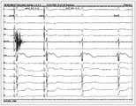
- the signal interference and the signal transmission of the connecting lineare very unstable, which affects the detection accuracy of the ECG monitoring analyzer (as shown in HIS 5-6 in Figure 20), making it difficult for the surgeon to accurately determine whether the screw-in end has reached the appropriate point. .
- the inventionprovides a connection line with stable signal transmission.
- a connecting wirecomprising a wire and a wire connector connected to the wire; further comprising a connector provided on the wire, the connector can be connected to at least two Device connection; through the setting of the connector, it can be connected to multiple devices at the same time, without additional temporary processing of the connection line, to avoid excessive contact between the wires of the connection line and the outside world, and reduce the interference of external signals on the signal transmission of the connection line.
- the ECG monitoring analyzercan timely and accurately monitor the intracavitary ECG and electrode impedance changes, and ensure that the electrode lead can be safely and accurately screwed into the patient's heart, so that the operation can be completed better and more safely.
- the connecting pieceincludes a connecting portion connected to the wire, a first connecting portion connected to the connecting portion, and a second connecting portion connected to the connecting portion;
- Each deviceis connected separately to avoid being connected in one place at the same time and causing signal interference, and further ensuring that the connection line can transmit signals in a timely and stable manner and ensure the accuracy of signal transmission.
- the first connecting partis provided with an exposed part for conducting electricity; the provision of the exposed part on the first connecting part facilitates the connection, clamping and fixing of the alligator clip, and reduces the screwing of the screw-in end of the electrode wire.
- the connection between the alligator clip and the first connection partis relatively rotated or displaced and then disconnected, which further ensures the stable transmission of the signal of the connection line.
- the second connecting partis provided with a plug slot; through the setting of the plug slot, it is convenient to quickly plug the connecting wire into the pacemaker programming instrument, and it is convenient for the devices to be quickly connected and fixed through the connecting wire. Therefore, the convenience of connection and replacement of the connecting wire is improved.
- itis inserted into the terminal of the pacemaker programming device through the socket, reducing the contact area with the outside world, thereby further reducing the external signal to the transmission signal in the connecting wire. The interference to ensure that the connection line can transmit signals in a timely and stable manner and ensure the accuracy of signal transmission.
- the first connecting portion on the connecting piececan form a plug-in fit with the plug groove on the adjacent connecting piece; through the plug-in fitting arrangement of the connecting piece, the signals of multiple devices can be simultaneously connected to In the same port, it is convenient for the operation of a specific program and the synchronization control of the corresponding equipment. At the same time, it is convenient for the surgeon to test the equipment according to the operation of the specific program, so as to ensure the normal operation of the equipment during the operation, so that the operation can be completed safely and accurately.
- a connecting rodis provided in the insertion groove, and a connecting hole that matches with the connecting rod is provided on the first connecting portion; through the setting of the connecting rod and the connecting hole, the adjacent connecting pieces It can quickly and accurately locate and connect with each other to improve the convenience of using the cable and the stability of the connection.
- the electrode leadis used to connect with the lead connector; when the electrode lead rotates, at least part of the lead connector can rotate with the rotation of the electrode lead; the arrangement of the lead connector makes the electrode lead The extreme end can be connected with the lead connector, so that when the surgeon rotates the electrode lead during the operation, at least part of the lead connector can rotate synchronously with the rotation of the electrode lead, so that the electrode lead will not be tangled.
- the surgeondoes not need to remove the electrode end from the alligator clip to untie the knotted part, and does not need an assistant to assist in rotating the electrode end connected to the alligator clip.
- the operationis more convenient and the wire connector can ensure that the electrical signal can be real-time, continuous and stable.
- the wire connectorincludes a rotating head that can rotate back and forth and a rotating connection part for connecting with the electrode lead.
- the rotating connection partis provided on the rotating head; the arrangement of the above structure enables the electrode lead to rotate through
- the connecting partis connected with the rotor on the wire joint, so that when the electrode wire rotates, the rotor can rotate with the rotation of the electrode wire, thereby achieving the purpose of preventing the electrode wire from being tangled and knotted.
- the wire connectoralso includes an elastic piece matched with the electrode wire; making the connection more stable and ensuring a more stable transmission of electrical signals, so that it can be displayed on the electrocardiogram monitoring analyzer and the pacemaker program controller The data is more accurate, which in turn enables the surgeon to better control the situation and make the operation more smoothly.
- the wire connectoralso includes a connector for connecting the rotor and the wire; to ensure the stable transmission of electrical signals, so that the surgeon can better monitor the patient's condition, and can more quickly and accurately Find the right spot.
- the present inventionmakes the electrode lead not entangled and knotted through the arrangement of the lead connector, so that during the operation, the ECG and electrode impedance changes can be continuously and accurately detected in real time, so that the surgeon can more smoothly Complete the operation, the risk is lower, the success rate is higher.
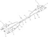
- FIG. 1is a schematic diagram of the three-dimensional structure of Embodiment 1 of the present invention.
- Figure 2is a schematic diagram of the three-dimensional structure of the mating of the wire connector and the wire in Figure 1;
- FIG. 3is a schematic diagram of a three-dimensional cross-sectional view of the mating of the wire connector and the wire in FIG. 1;
- Fig. 4is an enlarged schematic diagram of C in Fig. 3;
- Figure 5is a schematic diagram of the exploded structure of the coordination of the wire connector and the wire in Figure 1;
- Fig. 6is an enlarged schematic diagram of D in Fig. 5;
- Fig. 7is a perspective sectional view of the structure of the housing in Fig. 1;
- Fig. 8is a schematic diagram of the three-dimensional structure of the connector in Fig. 1;
- Embodiment 9is a schematic diagram of the three-dimensional structure of Embodiment 2 of the present invention.
- Embodiment 3 of the present inventionis a schematic diagram of the three-dimensional structure of Embodiment 3 of the present invention.
- FIG. 11is a schematic diagram of the three-dimensional structure of Embodiment 4 of the present invention.
- Figure 12is a schematic diagram of the mating structure of the connector and the wire in Figure 11;
- Fig. 13is a schematic diagram of the mating structure of the connector and the wire in Fig. 11 from another perspective;
- Fig. 14is an intracavity electrocardiogram displayed by an electrocardiogram monitoring analyzer in the mode of Fig. 11;
- Embodiment 15is a schematic diagram of the three-dimensional structure of Embodiment 5 of the present invention.
- FIG. 16is a schematic diagram of a three-dimensional structure of Embodiment 6 of the present invention.
- a connecting wireincludes a wire connector 2, an alligator clip 3, and a wire 1.
- the wire 1includes a first wire 11, a second wire 12, a third wire 13, a hub connector 14, and a wire connector.
- the first wireincludes a conductive core 111 and an insulating layer 112, the conductive core is made of copper or other conductive
- the materialis made of material.
- the material used in this embodimentis 60/0.08TC (tinned copper wire).
- the insulating layer 112is wrapped on the outside of the conductive core.
- the wire sleeve 17which is made of silicone material or other materials meeting medical standards. Because the wire sleeve fills the gap between the outer wall of the wire and the inner wall of the connecting ring, and the wire sleeve is made of silicone and the insulating layer is made of PVC material, the friction between the two is relatively large, so when When the wire is pulled away from the alligator clip by an external force, the wire sleeve plays the role of sharing the external force of the wire, so that the connection between the wire and the alligator clip is not easily damaged, and the two always maintain a stable electrical connection. Status, thereby improving the stability of data transmission, making the detected data more accurate, and making the operation safer and more successful.
- the hub connector 14is installed on the outside of the first wire, the second wire, and the third wire, and functions to bundle the three wires into one unit, so that the three wires and the alligator clips connected to the three wires are combined with each other.
- the wire connectoris not easy to twist and knot, and it is more convenient to use, avoid the problem of wasting time in arranging the wires, race against time for the operation, and further improve the success rate of the operation;
- the hub connectoris made of 25P black PVC material, which is in line with environmental protection RHOS;
- the tube 15is made of wear-resistant medical PVC material.
- first, second, and third wiresIt is sheathed on the outside of the bundled first, second, and third wires, and is preferably injection molded directly on the outside of the wires, which also prevents wires and alligators.
- the function of the clamp and the wire connector to tie the knot; the label sleeveis set on the outside of the hub, so that it is convenient to make some logos or other prompt texts on it.
- first wire 11is electrically connected to the crocodile clip 3, and the other end is electrically connected to the wire connector 2; both ends of the second wire 12 and the third wire 13 are electrically connected to the crocodile clip 3; the first wire 11
- the lead connector 2 on the upper leadis used to connect to the electrode lead of the pacemaker, and the alligator clip on the other end of the first lead is used to connect to the ECG monitoring analyzer and/or the pacemaker programmer; and the second lead 12 is in it
- the crocodile clip 3 on one endis used to hold the patient’s skin as an anode, and the crocodile clip on the other end is connected to the ECG monitor and/or pacing programmer; the crocodile clips at both ends of the third lead 13 are used as spares.
- the wire segments of the first wire 11 and the third wire 13 located in the header 15are integrated into one, so that the electrical signals of the two can communicate with each other; that is, the first wire 11 and the third wire 13 can be formed by Two strands or four thread ends of the same wire.
- the insulation layer of the three wires, the cover on the alligator clip and the outer skin on the wire connectorare produced in different colors during production.
- the first wire and the wire connector and alligator clip on itare all black; the second wire It is white, and the alligator clip on it is yellow; the third wire and the alligator clip on it are both red.
- the wire connector 2includes an outer skin 21, a shell 22, a rotor 23, a connector 24, and a middle sleeve 25;
- the shell 22is made of metal material, has conductive properties, is opened in a hollow cylindrical structure, and one end is opened There is a socket 221, a receiving cavity 222 is formed in the middle, and an interface 223 is formed at the other end;
- the rotor 23is made of conductive metal material, and copper material is used in this embodiment.
- the rotoris opened in a cylindrical structure, and the rotor is installed In the accommodating cavity 222, the rotor can be rotated in the accommodating cavity, and the outer surface of the rotor is always in contact with the cavity wall of the accommodating cavity, so as to realize the rotation and electrical connection between the rotor and the housing; the rotor is close to the socket 221
- the rotating connection part 231is a slot; preferably, the inner diameter of the rotating connection part 231 is the same as the inner diameter of the socket 221, so that the electrode lead is connected to the pacemaker.
- the extreme endcan pass through the socket 221 to be connected to the rotating connecting portion 231, and the edge of the socket can play a role in auxiliary fixing of the electrode end, preventing the electrode end from deflection, and the installation is more stable.
- an elastic piece 26is installed in the rotating connection portion 231, the elastic piece is made of metal material and has a certain degree of elasticity. In this embodiment, brass is used. In other embodiments, other conductive properties can also be used. And elastic metal material; the elastic piece includes a first fixing portion 261 and a second fixing portion 262, the first fixing portion is opened in a ring structure, and its outer diameter is slightly larger than the inner diameter of the rotating connecting portion 231, so that the elastic piece is installed in the rotating connection After the inner part, the first fixing part can form an interference fit with the rotating connection part, and the installation is more stable.
- the second fixing partis formed by at least part of the surface of the side of the first fixing part extending outwards, opening in an arc-shaped sheet structure, and the second fixing part The diameter gradually decreases from the end close to the first fixing part to the end far away from the first fixing part.
- a plurality of second fixing partsare arranged in a claw-like structure; when installing the elastic sheet, the second fixing part faces the rotating connection part, and then the elastic sheet It is placed in the rotating connection part, so that when the electrode end of the electrode wire is inserted into the rotating connection part, the second fixing part can be tightly attached to the surface of the electrode end, so that the electrode end can be affected by the elastic force of the second fixing part.
- the connectionis more stable, not easy to fall off, and at the same time, it can ensure that the electrode end and the rotor can always maintain the electrical connection state, thereby making the transmission of electrical signals more stable and accurate, providing the surgeon Reliable data support; and the electrode end is not easy to rotate relative to the shrapnel, to avoid the electrode end from being worn, and to ensure that the electrode end is connected to the pacemaker more stable, so that the pacemaker and electrode lead can always be stable to assist the patient Perform cardiac pacing; when the rotor is accidentally stuck and cannot rotate relative to the housing, because the elastic piece is elastic, the electrode end can rotate relative to the elastic piece, thereby avoiding damage to the rotor or the electrode wire; in the elastic piece 26 After being installed in the rotating connecting part 231, the rotating connecting part is closed, thereby forming a closed edge 233 at the edge of the socket, thereby fixing the elastic piece in the rotating connecting part to prevent the elastic piece from coming out with the electrode end pulled out .
- a third fixing portionis further provided on the elastic piece 26, and the third fixing portion is a convex portion formed by at least part of the surface of the inner side of the elastic piece, so as to make the contact between the elastic piece and the electrode end closer, and The fixing and anti-dropping effect of the electrode end is better.
- connection head 24includes a connection post 241, a connection groove 242 and a connection protrusion 243.
- the connection post 241is made of a metal material with good electrical conductivity. Thread, so that the connector can be installed in the interface to realize the threaded connection between the connector and the housing; the connecting groove 242 is opened on one end of the connecting column and is opened in a straight structure, which can facilitate the screwing of the connecting column into the interface , It also facilitates the electrical connection between the connector and the wire 1; the connecting protrusion 243 is opened at the other end of the connecting column, and is formed by extending at least part of the surface of the connecting column end; the end of the rotating head 23 close to the interface 223 is A rotating groove 232 is provided.
- the connecting protrusion 243is just inserted into the rotating groove 232, and the two fit with each other, and the connecting protrusion can rotate in the rotating groove, and The outer surface of the connecting convex part is always in contact with the groove wall of the rotating groove, so as to realize the rotating electrical coupling between the connecting head and the rotating head.
- the rotating grooveis opened in a flared structure, so that part of the outer surface of the connecting convex part can always contact with the groove wall of the rotating groove, and the rotating head is fixed in the accommodating cavity 222, and the connecting convex part and the rotating groove There is a gap between them to prevent the rotor from moving in the axial direction of the housing, so that the connection between the rotor and the electrode end of the electrode lead is more stable, and the fixing force of the connector to the rotor can be easily adjusted, so that The rotor can be installed stably without affecting the rotation of the rotor; and the contact area between the connecting protrusion and the rotor is always constant, which makes the data transmission more stable, thereby making the operation center electricity and electrode impedance
- the changes in the heart ratecan be accurately transmitted to the ECG monitoring analyzer and the programming instrument in real time, so that the surgeon can understand the various data parameters in the operation more clearly and accurately, so that the surgeon can better control the operation status Reduce the risk of surgery and increase the success rate of surgery
- the middle sleeve 25is sleeved on the outside of the first wire 11 on the side where the first wire is connected to the wire connector 2 instead of the wire sleeve 17.
- the middle sleeve 25is made of plastic material and has a certain degree of elasticity. Compared with rubber, the hardness is higher; when the first wire is electrically connected and fixed to the connector 24, the middle sleeve is pushed along the first wire into the flared section 224 formed on the housing 22, so that the first wire
- the connection with the connectoris not easy to move with the movement of the wire connector, thereby ensuring the stability of the connection between the first wire and the connector, and making the transmission of electrical signals more stable.
- the outer skin 21is made of medical silicone material or other insulating materials.
- the outer skinincludes a first segment body 211, a second segment body 212, and a third segment body 213.
- the first segment body 211covers the outside of the housing 22,
- the second section body 212is wrapped around the outer side of the middle sleeve 25, and the third section body is used to connect the first section body and the second section body, so that the middle sleeve is stably installed in the flaring section, and the middle sleeve is not It rotates relative to the housing, so that the connecting head can be fixed at a preset position, and there will be no loosening problem with the rotation of the rotating head, which further ensures the stability of the connection between the rotating head and the connecting head.
- the difference between this embodiment and Embodiment 1is that the first wire 11 and the third wire 13 are combined into a single wire, which is called the bus bar 18.
- One end of the bus baris divided into the first sub-line 181 and the first sub-line 181 and the second sub-line.
- Two sub-lines 182, the first sub-lineis connected with a wire connector 2, the second sub-line is connected with an alligator clip 3, and the other end of the bus bar is a third sub-line 183, and the third sub-line is connected with an alligator clip 3.
- the electric wire 1further includes a fourth wire 19, the fourth wire is also wrapped by the hub connector 14 and the hub 15, and one end of the fourth wire is connected with The other end of the wire connector 2 is connected with an alligator clip 3; that is, the first wire and the fourth wire are connected with the same parts, and the second wire and the third wire are connected with the same parts, which cooperate with each other to form two groups, which is convenient for the use of the two-electrode method.
- the difference between this embodiment and the first embodimentis that in order to make the connection more convenient in use, the three alligator clips 3 on the side where the wire connector 2 of the cable is not installed are replaced with the connector 4
- the connector 4includes a wiring portion 43, a first connecting portion 41 and a second connecting portion 42; the second connecting portion can be directly connected to the intracavity signal junction box of the ECG monitoring and analyzing instrument, and the second connecting portion is programmed with the pacemaker Instrument connection; through the setting of the first connection part and the second connection part, it can be connected to two devices at the same time, without additional temporary secondary processing of the connection line, reducing the excessive contact between the wire of the connection line and the outside world, and reducing the external environment
- the signalinterferes with the signal transmission of the connecting wire, so that the electrocardiogram monitoring analyzer can timely and accurately monitor the intracavitary electrocardiogram and the change of electrode impedance, and ensure that the electrode wire can be safely and accurately screwed into the patient's heart, so that the operation can be
- the connector 4is covered with a housing 48, which is made of insulating material, which can be plastic, silica gel or other materials; through the setting of the insulating housing, the conductive material in the connector can be separated from the outside world. Isolation, reduce external signal interference, the connection line can transmit signals in a timely and stable manner and ensure the accuracy of signal transmission.
- insulating materialwhich can be plastic, silica gel or other materials
- connection part, the first connection part and the second connection partare integrally consolidated and arranged in a "T" shape.
- the first connection part and the second connection partare respectively arranged on both sides of the connection part and are connected to the wires in the connection part. Connection; the arrangement of the first connection part and the second connection part on both sides of the connection part, while facilitating the connection, avoiding mutual interference of signals between the two first connection parts and the second connection part, and further ensuring that the connection line can be timely Stable signal transmission and ensure the accuracy of signal transmission.
- two exposed holes 411are opened on the side wall of the housing 48 at the first connecting portion 41, so that an exposed portion 44 is formed on the first connecting portion 41 to expose the internal metal so that the alligator clip can be directly clamped Hold at the exposed part to form an electrical connection with the exposed metal; the end of the first connecting part is provided with a connecting hole 47; the alligator clip on the lead of the pacemaker programmer can be clamped on the exposed part, It can facilitate the connection of the connecting cable and the pacemaker program controller, and further ensure the stable transmission of the signal of the connecting cable.
- the second connecting portion 42is provided with a plug-in slot 45, and a connecting rod 46 is provided in the plug-in slot, so that the second connection portion can be directly connected with the intracavity signal junction box on the ECG monitoring analyzer without
- the patch cordis convenient and fast, while reducing external interference, further reducing the interference of external signals on the transmission signal in the connection line, ensuring that the connection line can transmit signals in a timely and stable manner and ensuring the accuracy of signal transmission.
- first connecting portion on the connecting piecemay also form a plug fit with the second connecting portion of another adjacent connecting piece. Specifically, the first connecting portion is correspondingly inserted into the plug slot of the other connecting piece. At the same time, the connecting rod 46 can be inserted into the connecting hole 47, which makes it possible to meet different usage requirements and has stronger practicability.
- the difference between this embodiment and the fourth embodimentis that the first wire 11 and the third wire 13 are combined into a single wire, which is called the bus bar 18.
- One end of the bus baris divided into the first sub-line 181 and the first sub-line 181 and the third wire.
- the difference between this embodiment and the fourth embodimentis that: the electric wire 1 further includes a fourth wire 19, the fourth wire is also wrapped by the hub connector 14 and the hub 15, and one end of the fourth wire is connected with The other end of the wire connector 2 is connected with a connector 4; that is, the first wire and the fourth wire are connected by the same parts, and the second wire and the third wire are connected by the same parts, which cooperate with each other to form two groups, which is convenient for the use of the two-electrode method.
Landscapes
- Health & Medical Sciences (AREA)
- Engineering & Computer Science (AREA)
- Biomedical Technology (AREA)
- Nuclear Medicine, Radiotherapy & Molecular Imaging (AREA)
- Radiology & Medical Imaging (AREA)
- Life Sciences & Earth Sciences (AREA)
- Animal Behavior & Ethology (AREA)
- General Health & Medical Sciences (AREA)
- Public Health (AREA)
- Veterinary Medicine (AREA)
- Electrotherapy Devices (AREA)
Abstract
Description
Translated fromChinese本发明属于医疗器械技术领域,尤其是涉及一种连接线。The invention belongs to the technical field of medical devices, and particularly relates to a connecting wire.
心脏起搏器是一种植入于体内的电子治疗仪器,通过脉冲发生器发放由电池提供能量的电脉冲,通过导线电极的传导,刺激电极所接触的心肌,使心脏激动和收缩,从而达到治疗由于某些心律失常所致的心脏功能障碍的目的;其中,电极导线一端为电极端,用于连接起搏器,另一端为旋入端,用于植入病人心脏,电极端和旋入端均设有阴极和阳极;由于所述电极端阳极为环状结构,因此又称为阳极环。A cardiac pacemaker is an electronic therapy instrument implanted in the body. The pulse generator emits electrical pulses powered by the battery. Through the conduction of the lead electrodes, it stimulates the myocardium contacted by the electrodes, excites and contracts the heart, thereby achieving treatment The purpose of cardiac dysfunction caused by certain arrhythmia; among them, one end of the lead wire is the electrode terminal, which is used to connect the pacemaker, and the other end is the screw-in terminal, which is used to implant the patient's heart, the electrode terminal and the screw-in terminal Both are provided with a cathode and an anode; since the anode at the electrode end has a ring structure, it is also called an anode ring.
术者在手术过程中,将电极导线的旋入端送入病人心脏并贴壁心肌内膜后,需要通过转动电极导线将电极导线的螺旋头阴极旋入心肌;而在旋入端拧入的过程中,需要用心电监测分析仪与起搏器程控仪随时监测起搏或非起搏状态下旋入阴极端的腔内心电图以及电极阻抗变化情况,透过这些参数变化的观测,使得术者能够更准确地把控电极旋入深度,以便手术能够更好、更安全地完成。During the operation, after the surgeon sends the screw-in end of the electrode lead into the patient’s heart and adheres to the endocardium, he needs to screw the screw head cathode of the electrode lead into the myocardium by rotating the electrode lead; and the screw-in end is screwed in. During the process, it is necessary to use an electrocardiogram monitoring analyzer and a pacemaker programmer to monitor the changes in the electrocardiogram and the electrode impedance of the cavity screwed into the cathode in the pacing or non-pacing state at any time. Through the observation of the changes in these parameters, the surgeon The control electrode can be screwed into the depth more accurately, so that the operation can be completed better and more safely.
现有技术中,电极导线的电极端需要与心电监测分析仪和起搏器程控仪同时连接;电极导线与心电监测分析仪是通过连接线的鳄鱼夹和另一根转接线连接的,具体的,转接线一端插入到心电监测分析仪的腔内信号接线盒上,再将转接线另一端上的绝缘外皮剥落,露出金属,然后将连接线的鳄鱼夹夹持在该剥皮金属上,实现鳄鱼夹与转接线的连接,再将电极导线与连接线相连,使得心腔内心电信号通过集 成的腔内信号接线盒与心电监测分析仪相连;再将起搏器程控仪上自带的连接线上的鳄鱼夹夹持在转接线的剥皮金属上,实现电机导线、连接线及起搏器程控仪之间的连接;但是该种连接方式由于没有外皮的阻隔,极易受到外界信号的干扰,连接线的信号传递很不稳定,影响心电监测分析仪的检测精度(如图20中HIS 5-6所示),致使术者难以准确把握旋入端是否抵达合适的位点。In the prior art, the electrode end of the electrode lead needs to be connected to the ECG monitoring analyzer and the pacemaker program controller at the same time; the electrode lead and the ECG monitoring analyzer are connected through the alligator clip of the connecting wire and another patch cord. Specifically, one end of the patch cord is inserted into the signal junction box in the cavity of the ECG monitoring analyzer, and then the insulation coating on the other end of the patch cord is peeled off to expose the metal, and then the alligator clip of the cord is clamped on the stripped metal , To realize the connection between the alligator clip and the patch cord, and then connect the electrode lead to the connecting line, so that the ECG signal in the heart cavity is connected to the ECG monitoring analyzer through the integrated intracavity signal junction box; The alligator clip on the connecting wire of the strap is clamped on the stripped metal of the transfer cable to realize the connection between the motor wire, the connecting wire and the pacemaker program controller; however, this connection method is extremely vulnerable to the outside world because there is no outer skin barrier. The signal interference and the signal transmission of the connecting line are very unstable, which affects the detection accuracy of the ECG monitoring analyzer (as shown in HIS 5-6 in Figure 20), making it difficult for the surgeon to accurately determine whether the screw-in end has reached the appropriate point. .
发明内容Summary of the invention
本发明提供了一种信号传递稳定的连接线。The invention provides a connection line with stable signal transmission.
为了实现上述目的,本发明采用以下技术方案:一种连接线,包括电线和与所述电线相连的导线接头;还包括设于所述电线上的连接件,该连接件可同时与至少两个设备相连;通过连接件的设置,可同时与多个设备进行连接,无需额外对连接线进行临时加工,避免连接线的导线与外界过多接触,降低外界信号对连接线信号传递的干扰,从而使心电监测分析仪能及时准确的监测到腔内心电图以及电极阻抗变化情况,保证电极导线能安全准确旋入到病人心脏中,以便手术能够更好、更安全地完成。In order to achieve the above objective, the present invention adopts the following technical solutions: a connecting wire, comprising a wire and a wire connector connected to the wire; further comprising a connector provided on the wire, the connector can be connected to at least two Device connection; through the setting of the connector, it can be connected to multiple devices at the same time, without additional temporary processing of the connection line, to avoid excessive contact between the wires of the connection line and the outside world, and reduce the interference of external signals on the signal transmission of the connection line. The ECG monitoring analyzer can timely and accurately monitor the intracavitary ECG and electrode impedance changes, and ensure that the electrode lead can be safely and accurately screwed into the patient's heart, so that the operation can be completed better and more safely.
进一步的,所述连接件包括与所述电线相连的接线部、与所述接线部相连的第一连接部及与所述接线部相连的第二连接部;通过连接件的设置,可将多个设备分别连接,避免同时连接在一处以至产生信号干扰,进一步保证连接线能及时稳定的传递信号并保证信号传递的准确性。Further, the connecting piece includes a connecting portion connected to the wire, a first connecting portion connected to the connecting portion, and a second connecting portion connected to the connecting portion; Each device is connected separately to avoid being connected in one place at the same time and causing signal interference, and further ensuring that the connection line can transmit signals in a timely and stable manner and ensure the accuracy of signal transmission.
进一步的,所述第一连接部上设有用于导电的裸露部;通过第一 连接部上的裸露部的设置,可方便鳄鱼夹的连接夹持和固定,降低当电极导线的旋入端旋入时鳄鱼夹与第一连接部的连接处产生相对旋转或位移后断开的情况发生,进一步保证连接线的信号的稳定传输。Further, the first connecting part is provided with an exposed part for conducting electricity; the provision of the exposed part on the first connecting part facilitates the connection, clamping and fixing of the alligator clip, and reduces the screwing of the screw-in end of the electrode wire. When entering, the connection between the alligator clip and the first connection part is relatively rotated or displaced and then disconnected, which further ensures the stable transmission of the signal of the connection line.
进一步的,所述第二连接部上设有插接槽;通过插接槽的设置,可便于将连接线快速插接在起搏器程控仪上,方便设备间通过连接线进行快速连接固定,从而提高连接线的使用连接和更换的便捷性同时通过插接槽插接入所述起搏器程控仪的接线端内,减少与外界的接触面积,从而进一步减少外界信号对连接线内传输信号的干扰,保证连接线能及时稳定的传递信号并保证信号传递的准确性。Further, the second connecting part is provided with a plug slot; through the setting of the plug slot, it is convenient to quickly plug the connecting wire into the pacemaker programming instrument, and it is convenient for the devices to be quickly connected and fixed through the connecting wire. Therefore, the convenience of connection and replacement of the connecting wire is improved. At the same time, it is inserted into the terminal of the pacemaker programming device through the socket, reducing the contact area with the outside world, thereby further reducing the external signal to the transmission signal in the connecting wire. The interference to ensure that the connection line can transmit signals in a timely and stable manner and ensure the accuracy of signal transmission.
进一步的,所述连接件上的第一连接部可与相邻所述连接件上的插接槽形成插接配合;通过连接件的插接配合设置,可同时将多个设备的信号连接于同一端口内,方便对特定程序的运行和相应设备的同步控制,同时方便术者根据特定程序的运行情况对设备进行测试,从而保证设备在术中的正常运行,以便手术能够安全准确地完成。Further, the first connecting portion on the connecting piece can form a plug-in fit with the plug groove on the adjacent connecting piece; through the plug-in fitting arrangement of the connecting piece, the signals of multiple devices can be simultaneously connected to In the same port, it is convenient for the operation of a specific program and the synchronization control of the corresponding equipment. At the same time, it is convenient for the surgeon to test the equipment according to the operation of the specific program, so as to ensure the normal operation of the equipment during the operation, so that the operation can be completed safely and accurately.
进一步的,所述插接槽内设有连接杆,所述第一连接部上设有与所述连接杆相配合的连接孔;通过连接杆和连接孔的设置,使相邻的连接件之间能快速准确的定位和连接配合,提高连接线使用的便捷性和连接的稳固性。Further, a connecting rod is provided in the insertion groove, and a connecting hole that matches with the connecting rod is provided on the first connecting portion; through the setting of the connecting rod and the connecting hole, the adjacent connecting pieces It can quickly and accurately locate and connect with each other to improve the convenience of using the cable and the stability of the connection.
进一步的,所述电极导线用于与所述导线接头相连;当电极导线转动时,所述导线接头的至少部分可以随着电极导线的转动而转动;通过导线接头的设置,使得电极导线的电极端能够与导线接头相连,从而使得当术者在手术过程中转动电极导线时,导线接头的至少部分 能够随着电极导线的转动而同步转动,从而使得电极导线不会出现缠绕打结的情况,术者无需将电极端从鳄鱼夹上取下来解开缠绕打结的部分,也无需助手辅助转动与鳄鱼夹相连的电极端,操作更为方便,保证导线接头能够将电信号实时、持续、稳定、准确的传导到心电监测分析仪和起搏器程控仪上,进而保证术者能够实时掌握心电和电极阻抗的变化,使得术者能够准确的把握旋入端是否抵达位点或拧入时是否突破间隔,保证拧入位点的准确,减轻患者的痛苦,使得手术更为快速的完成,且手术成功率更高;同时由于电极端不再被鳄鱼夹夹持固定,所以不会对电极端造成损伤,从而使得电极导线与起搏器相连时,连接更为稳定,进而保证起搏器始终能够稳定的起到辅助患者心脏起搏的作用。Further, the electrode lead is used to connect with the lead connector; when the electrode lead rotates, at least part of the lead connector can rotate with the rotation of the electrode lead; the arrangement of the lead connector makes the electrode lead The extreme end can be connected with the lead connector, so that when the surgeon rotates the electrode lead during the operation, at least part of the lead connector can rotate synchronously with the rotation of the electrode lead, so that the electrode lead will not be tangled. The surgeon does not need to remove the electrode end from the alligator clip to untie the knotted part, and does not need an assistant to assist in rotating the electrode end connected to the alligator clip. The operation is more convenient and the wire connector can ensure that the electrical signal can be real-time, continuous and stable. 、Accurately conduct to the ECG monitoring analyzer and the pacemaker programming instrument, thus ensuring that the surgeon can grasp the changes of the ECG and electrode impedance in real time, so that the surgeon can accurately grasp whether the screw-in end has reached the position or screwed in Whether to break through the interval, ensure the accuracy of the screw-in site, reduce the pain of the patient, make the operation more quickly completed, and the success rate of the operation is higher; at the same time, because the electrode end is no longer clamped and fixed by the alligator clip, it will not be correct. The electrode end is damaged, so that when the electrode lead is connected to the pacemaker, the connection is more stable, thereby ensuring that the pacemaker can always stably play a role in assisting the patient's cardiac pacing.
进一步的,所述导线接头包括可来回转动的转头和用于与电极导线相连的转动连接部,该转动连接部设于所述转头上;通过上述结构的设置,使得电极导线能够通过转动连接部与导线接头上的转头相连,从而使得电极导线转动时,转头能够随着电极导线的转动而转动,从而实现了防止电极导线缠绕打结的目的。Further, the wire connector includes a rotating head that can rotate back and forth and a rotating connection part for connecting with the electrode lead. The rotating connection part is provided on the rotating head; the arrangement of the above structure enables the electrode lead to rotate through The connecting part is connected with the rotor on the wire joint, so that when the electrode wire rotates, the rotor can rotate with the rotation of the electrode wire, thereby achieving the purpose of preventing the electrode wire from being tangled and knotted.
进一步的,所述导线接头还包括与所述电极导线相配合的弹片;使得连接更为稳定,保证电信号能够更为稳定的传输,从而使得显示在心电监测分析仪和起搏器程控仪上的数据更为准确,进而使得术者能够更好的掌控局面,使得手术进行的更为顺利。Further, the wire connector also includes an elastic piece matched with the electrode wire; making the connection more stable and ensuring a more stable transmission of electrical signals, so that it can be displayed on the electrocardiogram monitoring analyzer and the pacemaker program controller The data is more accurate, which in turn enables the surgeon to better control the situation and make the operation more smoothly.
进一步的,所述导线接头还包括用于连接所述转头和所述电线的连接头;保证电信号的稳定传输,使得术者能够更好的监控患者的状 况,能够更为快速和准确的找到正确的位点。Further, the wire connector also includes a connector for connecting the rotor and the wire; to ensure the stable transmission of electrical signals, so that the surgeon can better monitor the patient's condition, and can more quickly and accurately Find the right spot.
综上所述,本发明通过导线接头的设置,使得电极导线不会缠绕打结,从而使得在手术过程中,能够实时持续准确的检测心电与电极阻抗变化,进而使得术者能够更顺利的完成手术,风险更低,成功率更高。To sum up, the present invention makes the electrode lead not entangled and knotted through the arrangement of the lead connector, so that during the operation, the ECG and electrode impedance changes can be continuously and accurately detected in real time, so that the surgeon can more smoothly Complete the operation, the risk is lower, the success rate is higher.
图1为本发明实施例1的立体结构示意图;FIG. 1 is a schematic diagram of the three-dimensional structure of
图2为图1中导线接头与电线的配合立体结构示意图;Figure 2 is a schematic diagram of the three-dimensional structure of the mating of the wire connector and the wire in Figure 1;
图3为图1中导线接头与电线的配合立体剖视结构示意图;3 is a schematic diagram of a three-dimensional cross-sectional view of the mating of the wire connector and the wire in FIG. 1;
图4为图3中C处的放大示意图;Fig. 4 is an enlarged schematic diagram of C in Fig. 3;
图5为图1中导线接头与电线的配合爆炸结构示意图;Figure 5 is a schematic diagram of the exploded structure of the coordination of the wire connector and the wire in Figure 1;
图6为图5中D处的放大示意图;Fig. 6 is an enlarged schematic diagram of D in Fig. 5;
图7为图1中壳体的立体剖视结构示意图;Fig. 7 is a perspective sectional view of the structure of the housing in Fig. 1;
图8为图1中连接头的立体结构示意图;Fig. 8 is a schematic diagram of the three-dimensional structure of the connector in Fig. 1;
图9为本发明实施例2的立体结构示意图;9 is a schematic diagram of the three-dimensional structure of
图10为本发明实施例3的立体结构示意图;10 is a schematic diagram of the three-dimensional structure of
图11为本发明实施例4的立体结构示意图;11 is a schematic diagram of the three-dimensional structure of
图12为图11中连接件与电线的配合结构示意图;Figure 12 is a schematic diagram of the mating structure of the connector and the wire in Figure 11;
图13为图11中连接件与电线另一个视角的配合结构示意图;Fig. 13 is a schematic diagram of the mating structure of the connector and the wire in Fig. 11 from another perspective;
图14为图11方式下心电监测分析仪显示的腔内心电图;Fig. 14 is an intracavity electrocardiogram displayed by an electrocardiogram monitoring analyzer in the mode of Fig. 11;
图15为本发明实施例5的立体结构示意图;15 is a schematic diagram of the three-dimensional structure of Embodiment 5 of the present invention;
图16为本发明实施例6的立体结构示意图。FIG. 16 is a schematic diagram of a three-dimensional structure of Embodiment 6 of the present invention.
实施例1:Example 1:
如图1-8所示,一种连接线,包括导线接头2、鳄鱼夹3及电线1,其中电线1包括第一导线11、第二导线12、第三导线13、集线接头14、集线管15、标套16及线套17;第一导线11直径为1mm-2mm,优选为1.5mm±0.05mm;第一导线包括导电芯111和绝缘层112,该导电芯由铜或其他导电材料制成,本实施例中采用的材料为60/0.08TC(镀锡铜丝),绝缘层112包覆在导电芯外侧,呈管状结构开设,由PVC材料制成;第二导线12和第三导线13的尺寸、结构与第一导线11的尺寸、结构相同;第一导线、第二导线及第三导线上均套设有线套17,该线套由硅胶材料或其他满足医用标准的材料制成;由于线套将导线外壁与连接环内壁之间的间隙给填充满了,且线套由硅胶制成,绝缘层由PVC材料制成,两者之间的摩擦力较大,所以当导线受到外力而被往远离鳄鱼夹的方向拉扯时,线套起到了分担导线受到的外力的作用,从而使得导线与鳄鱼夹之间的连接固定不易被损坏,保证两者始终保持稳定的电连状态,进而提高了数据传输的稳定性,使得检测到的数据更为准确,进而使得手术的安全性和成功率更高。As shown in Figure 1-8, a connecting wire includes a
进一步的,集线接头14安装在第一导线、第二导线及第三导线的外侧,起到将三根导线收束成为一股的作用,从而使得三根导线以及连接在三根导线上的鳄鱼夹和导线接头不易缠绕、打结,使用更为方便,避免整理导线浪费时间的问题,为手术争分夺秒,进一步提高 手术的成功率;该集线接头由25P黑色PVC材料制成,符合环保RHOS;集线管15由耐磨医疗PVC材料制成,其套设被收束后的第一导线、第二导线及第三导线的外侧,优选为直接注塑成型在导线的外侧,同样起到防止导线、鳄鱼夹及导线接头打结的作用;标套套设在集线管的外侧,方便在其上做一些标识或其他提示文字。Further, the
进一步的,第一导线11的一端与鳄鱼夹3电连,另一端与导线接头2电连;第二导线12和第三导线13的两端则均与鳄鱼夹3电连;第一导线11上的导线接头2用于与起搏器的电极导线相连,第一导线另一端上的鳄鱼夹则用于与心电监测分析仪和/或起搏器程控仪相连;而第二导线12其中一端上的鳄鱼夹3用于夹持患者的皮肤,作为阳极,另一端上的鳄鱼夹则与心电监测分析仪和/或起搏程控仪相连;第三导线13两端的鳄鱼夹作为备用,监测过程中,根据不同情况,可以选择将第三导线一端上的鳄鱼夹夹在电极端的阳极环上,另一端上的鳄鱼夹与心电监测分析仪和起搏程控仪相连,从而获得更多的植入参数。Further, one end of the
于其他实施例中,第一导线11和第三导线13位于集线管15内的导线段集成为一根,使得两者的电信号互通;即第一导线11和第三导线13可以是由同一根导线分出来的两股子线或四个线头。In other embodiments, the wire segments of the
为了便于区分,生产时将三根导线的绝缘层、鳄鱼夹上的夹罩以及导线接头上的外皮生产为不同颜色,其中第一导线及其上的导线接头和鳄鱼夹均呈黑色;第二导线呈白色,其上的鳄鱼夹呈黄色;第三导线及其上的鳄鱼夹均呈红色。In order to facilitate the distinction, the insulation layer of the three wires, the cover on the alligator clip and the outer skin on the wire connector are produced in different colors during production. The first wire and the wire connector and alligator clip on it are all black; the second wire It is white, and the alligator clip on it is yellow; the third wire and the alligator clip on it are both red.
具体的,导线接头2包括外皮21、壳体22、转头23、连接头24及中套25;壳体22由金属材料制成,具有导电性能,呈中空的圆柱体结构开设,其一端开设有插口221,中部形成有容纳腔222,另一端形成有接口223;转头23由导电金属材料制成,本实施例中采用的是铜材料,该转头呈圆柱体结构开设,转头安装在容纳腔222内,转头可以在容纳腔内转动,且转头的外表面始终与容纳腔的腔壁相接触,实现转头与壳体之间的转动电连配合;转头靠近插口221的一端开设有转动连接部231,本实施例中,该转动连接部为一个插槽;优选的,转动连接部231的内径与插口221的内径相同,从而使得电极导线与起搏器相连的电极端能够穿过插口221与转动连接部231相连,同时插口的边缘能够起到对电极端的辅助固定作用,防止电极端发生偏转,安装更为稳定。Specifically, the
进一步的,在转动连接部231内安装了一个弹片26,该弹片由金属材料制成,具有一定的弹性,本实施例中采用的是黄铜,于其他实施例中也可采用其他具有导电性能和弹性的金属材料制成;弹片包括第一固定部261和第二固定部262,第一固定部呈环形结构开设,其外径略大于转动连接部231的内径,从而使得弹片安装入转动连接部内后,第一固定部能够与转动连接部形成过盈配合,安装更为稳定,且电极导线的电极端插入后,在电极导线旋转时,能够带动弹片和转头一起旋转,而弹片却难以相对于转头转动,从而使得电信号传输更为稳定;第二固定部则由第一固定部侧面的至少部分表面向外延伸形成,呈弧形的片状结构开设,且第二固定部的直径从靠近第一固定部 的一端往远离第一固定部的一端逐渐减小,多个第二固定部呈爪状结构布设;安装弹片时,将第二固定部朝向转动连接部,然后将弹片置入转动连接部内,从而使得当电极导线的电极端插入转动连接部内后,第二固定部能够紧贴在电极端的表面上,使得电极端能够在第二固定部的弹性力作用下,被夹持固定在转动连接部内,连接更为稳定,不易脱落,同时又能够保证电极端和转头之间始终能够保持电连状态,进而使得电信号的传输更为稳定且准确,为术者提供可靠的数据支持;而且电极端也不易相对于弹片转动,避免电极端被磨损,进而保证电极端与起搏器连接时连接较为稳定,使得起搏器和电极导线始终能够稳定的起到辅助患者进行心脏起搏的作用;而当转头意外卡住而无法相对于壳体转动时,则由于弹片具有弹性,电极端又可以相对于弹片转动,从而避免转头或电极导线损坏;在弹片26安装入转动连接部231内后,对转动连接部做收口处理,从而在插口的口沿处形成了收口边233,从而将弹片固定在转动连接部内,防止弹片随着电极端的拔出而脱出。Further, an
优选的,在弹片26上还开设有第三固定部,该第三固定部由弹片内侧的至少部分表面向外延伸形成的凸部,从而使得弹片与电极端之间的接触更为紧密,且对电极端的固定防脱效果更好。Preferably, a third fixing portion is further provided on the
进一步的,连接头24包括连接柱241、连接槽242及连接凸部243,连接柱241由导电性能好的金属材料制成,其外表面开设有外螺纹,接口223内开设有相对应的内螺纹,从而使得连接头能够安装到接口内,实现连接头与壳体的螺纹连接;连接槽242开设在连接柱 的一端上,呈一字型结构开设,既能够方便将连接柱旋入接口内,也方便连接头与电线1之间的电连;连接凸部243则开设在连接柱的另一端,由连接柱端部的至少部分表面向外延伸形成;转头23靠近接口223的一端则开设有转槽232,当转头安装在壳体内且连接头与壳体螺接后,连接凸部243正好嵌入转槽232内,两者相互契合,连接凸部可在转槽内转动,且连接凸部的外表面始终与转槽的槽壁相贴合,从而实现连接头与转头之间的转动电连配合。Further, the
优选的,转槽呈扩口状结构开设,从而使得连接凸部始终又部分外表面能够与转槽的槽壁相接触,并将转头固定在容纳腔222内,且连接凸部与转槽之间留有空隙,防止转头沿壳体的轴向方向移动,使得转头与电极导线的电极端之间的连接更为稳定,并且能够方便的调节连接头对转头的固定力,使得转头能够安装稳定的同时,又不会影响到转头的转动;而且连接凸部与转头之间的接触面积始终较为恒定,使得数据的传输更为稳定,从而使得手术中心电与电极阻抗的变化能够实时精准的输送至心电监测分析仪和程控仪上,进而使得术者对手术中的各项数据参数了解的更为清楚精准,使得术者能够更好的把控手术状况,从而降低手术风险,提高手术的成功率。Preferably, the rotating groove is opened in a flared structure, so that part of the outer surface of the connecting convex part can always contact with the groove wall of the rotating groove, and the rotating head is fixed in the
进一步的,中套25套设在第一导线11的外侧,位于第一导线与导线接头2连接的一侧,替代线套17,该中套25由塑料材料制成,具有一定弹性的同时,相较于橡胶来说硬度更高;当第一导线与连接头24电连固定后,将中套沿第一导线推入形成与壳体22上的扩口段224内,从而使得第一导线与连接头的连接处不易随着导线接头的移 动而移动,进而保证了第一导线与连接头之间连接的稳定性,使得电信号的传输更为稳定。Further, the
进一步的,外皮21由医用硅胶材料或其他绝缘材料制成,外皮包括第一段体211、第二段体212及第三段体213,第一段体211包覆在壳体22的外侧,第二段体212包覆在中套25的外侧,第三段体则用于连接第一段体和第二段体,从而使得中套被稳定的安装在扩口段内,并且中套不会相对于壳体发生转动,从而使得连接头能够被固定在预设位置上,不会随着转头的转动而出现松动的问题,进一步保证了转头与连接头之间连接的稳定性。Further, the
实施例2:Example 2:
如图9所示,本实施例与实施例1的区别在于:将第一导线11和第三导线13合并为一根导线,称之为母线18,母线一端分出第一子线181和第二子线182,第一子线连接有导线接头2,第二子线连接有鳄鱼夹3,而母线的另一端为第三子线183,第三子线连接有一个鳄鱼夹3。As shown in Figure 9, the difference between this embodiment and
实施例3:Example 3:
如图10所示,本实施例与实施例1的区别在于:电线1还包括第四导线19,第四导线也被集线接头14和集线管15包裹在内,第四导线一端连接有导线接头2,另一端连接有鳄鱼夹3;即第一导线和第四导线连接的部件相同,第二导线与第三导线连接的部件相同,相互配合形成两组,方便双电极法的使用。As shown in Fig. 10, the difference between this embodiment and the first embodiment is: the
实施例4:Example 4:
如图11-14所示,本实施例与实施例1的区别在于:为了使用时的连接更为方便,将本连接线未安装导线接头2一侧的三个鳄鱼夹3替换为连接件4;连接件4包括接线部43、第一连接部41及第二连接部42;第二连接部可以直接与心电监测分析仪的腔内信号接线盒连接,第二连接部与起搏器程控仪连接;通过第一连接部和第二连接部的设置,可同时与两个设备进行连接,无需额外对连接线进行临时的二次加工,减少连接线的导线与外界过多接触,降低外界信号对连接线信号传递的干扰,从而使心电监测分析仪能及时准确的监测到腔内心电图以及电极阻抗变化情况,保证电极导线能安全准确旋入到病人心脏中,以便手术能够更好、更安全地完成。As shown in Figures 11-14, the difference between this embodiment and the first embodiment is that in order to make the connection more convenient in use, the three
进一步的,连接件4上包覆有外壳48,外壳为绝缘材料制成,可以为塑料,也可以是硅胶或其他材料制成;通过绝缘外壳的设置,可将连接件内的导电材质与外界隔离,减少外界的信号干扰,连接线能及时稳定的传递信号并保证信号传递的准确性。Further, the
进一步的,接线部、第一连接部及第二连接部一体固结并呈“T”形设置,第一连接部和第二连接部分别设置于接线部的两侧,与接线部中的电线连接;第一连接部和第二连接部分布于接线部两侧的设置,方便连接的同时,避免两个第一连接部和第二连接部之间信号的相互干扰,进一步保证连接线能及时稳定的传递信号并保证信号传递的准确性。Further, the connection part, the first connection part and the second connection part are integrally consolidated and arranged in a "T" shape. The first connection part and the second connection part are respectively arranged on both sides of the connection part and are connected to the wires in the connection part. Connection; the arrangement of the first connection part and the second connection part on both sides of the connection part, while facilitating the connection, avoiding mutual interference of signals between the two first connection parts and the second connection part, and further ensuring that the connection line can be timely Stable signal transmission and ensure the accuracy of signal transmission.
进一步的,第一连接部41处的外壳48侧壁上开设有两个裸露孔411,从而在第一连接部41上形成了裸露部44,将内部的金属裸露 出来,使得鳄鱼夹能够直接夹持在裸露部处,与裸露出的金属形成电连接;第一连接部的端部上开设有连接孔47;起搏器程控仪自带的导线上的鳄鱼夹可夹持于裸露部上,可方便连接线与起搏器程控仪的连接,进一步保证连接线的信号的稳定传输。Further, two exposed
进一步的,第二连接部42上开设有插接槽45,插接槽内开设有连接杆46,从而使得第二连接部可以直接与心电监测分析仪上的腔内信号接线盒连接,无需转接线,方便快捷的同时,降低了外部干扰,进一步减少外界信号对连接线内传输信号的干扰,保证连接线能及时稳定的传递信号并保证信号传递的准确性。Further, the second connecting
进一步的,连接件上的第一连接部也可与相邻的另一个连接件的第二连接部形成插接配合,具体为,第一连接部对应插接入另一个连接件的插接槽45内,同时连接杆46可以插入连接孔47内,使得可以应对不同的使用需求,实用性更强。Further, the first connecting portion on the connecting piece may also form a plug fit with the second connecting portion of another adjacent connecting piece. Specifically, the first connecting portion is correspondingly inserted into the plug slot of the other connecting piece. At the same time, the connecting
实施例5:Example 5:
如图15所示,本实施例与实施例4的区别在于:将第一导线11和第三导线13合并为一根导线,称之为母线18,母线一端分出第一子线181和第二子线182,第一子线连接有导线接头2,第二子线连接有鳄鱼夹3,而母线的另一端为第三子线183,第三子线连接有一个连接件4。As shown in FIG. 15, the difference between this embodiment and the fourth embodiment is that the
实施例6:Example 6:
如图16所示,本实施例与实施例4的区别在于:电线1还包括第四导线19,第四导线也被集线接头14和集线管15包裹在内,第 四导线一端连接有导线接头2,另一端连接有连接件4;即第一导线和第四导线连接的部件相同,第二导线与第三导线连接的部件相同,相互配合形成两组,方便双电极法的使用。As shown in Figure 16, the difference between this embodiment and the fourth embodiment is that: the
Claims (10)
Translated fromChinesePriority Applications (1)
| Application Number | Priority Date | Filing Date | Title |
|---|---|---|---|
| US17/859,042US12272901B2 (en) | 2020-01-07 | 2022-07-07 | Connecting with a wire joint having rotatable head |
Applications Claiming Priority (4)
| Application Number | Priority Date | Filing Date | Title |
|---|---|---|---|
| CN202020024478.9 | 2020-01-07 | ||
| CN202020024478.9UCN212547970U (en) | 2020-01-07 | 2020-01-07 | A kind of connecting wire for pacemaker implantation test |
| CN202023031905.5 | 2020-12-16 | ||
| CN202023031905.5UCN215343280U (en) | 2020-12-16 | 2020-12-16 | a connecting line |
Related Child Applications (1)
| Application Number | Title | Priority Date | Filing Date |
|---|---|---|---|
| US17/859,042Continuation-In-PartUS12272901B2 (en) | 2020-01-07 | 2022-07-07 | Connecting with a wire joint having rotatable head |
Publications (1)
| Publication Number | Publication Date |
|---|---|
| WO2021139608A1true WO2021139608A1 (en) | 2021-07-15 |
Family
ID=76787455
Family Applications (1)
| Application Number | Title | Priority Date | Filing Date |
|---|---|---|---|
| PCT/CN2020/142590CeasedWO2021139608A1 (en) | 2020-01-07 | 2020-12-31 | Connecting line |
Country Status (2)
| Country | Link |
|---|---|
| US (1) | US12272901B2 (en) |
| WO (1) | WO2021139608A1 (en) |
Cited By (1)
| Publication number | Priority date | Publication date | Assignee | Title |
|---|---|---|---|---|
| CN115347413A (en)* | 2022-10-18 | 2022-11-15 | 国网浙江省电力有限公司宁波供电公司 | Quick connect joint for grounding wire |
Families Citing this family (2)
| Publication number | Priority date | Publication date | Assignee | Title |
|---|---|---|---|---|
| US11944828B2 (en) | 2020-09-24 | 2024-04-02 | Medtronic, Inc. | Rotatable adapter for connecting implantable medical leads to test devices |
| WO2025107033A1 (en)* | 2023-11-22 | 2025-05-30 | Chapman Darius | Systems, devices, and methods for rotatable electrical connection with a pacemaker |
Citations (4)
| Publication number | Priority date | Publication date | Assignee | Title |
|---|---|---|---|---|
| US20130021040A1 (en)* | 2011-07-21 | 2013-01-24 | Pacesetter, Inc. | Connector sleeve for a lead of an internal pulse generator |
| CN205646265U (en)* | 2016-04-21 | 2016-10-12 | 东莞市宝铼珀塑胶电子有限公司 | Mobile phone transmission port data signal hub switching device |
| CN109529195A (en)* | 2019-01-24 | 2019-03-29 | 宁波市第二医院 | A kind of cathode inner-rotary type Pacemaker implantation p-wire |
| CN209848150U (en)* | 2019-01-24 | 2019-12-27 | 宁波市第二医院 | Pacemaker implantation test wire with cathode and anode capable of rotating simultaneously |
Family Cites Families (26)
| Publication number | Priority date | Publication date | Assignee | Title |
|---|---|---|---|---|
| US5882228A (en)* | 1996-12-17 | 1999-03-16 | The Whitaker Corporation | Self-terminating electrical connector assembly |
| US6829779B1 (en)* | 1998-09-16 | 2004-12-07 | Webtv Networks, Inc. | User interface for entertainment system setup |
| US6169879B1 (en)* | 1998-09-16 | 2001-01-02 | Webtv Networks, Inc. | System and method of interconnecting and using components of home entertainment system |
| TW563943U (en)* | 2003-02-27 | 2003-11-21 | Tatung Co | IEEE-1394 adaptor cable |
| US7285021B2 (en)* | 2004-02-04 | 2007-10-23 | Oqo, Inc. | Docking cable |
| US20060013410A1 (en)* | 2004-04-20 | 2006-01-19 | Wurtz Michael J | Mobile-telephone adapters for automatic-noise-reduction headphones |
| TWM271291U (en)* | 2004-10-04 | 2005-07-21 | Inventec Multimedia & Telecom | Connector |
| US7057108B1 (en)* | 2005-08-03 | 2006-06-06 | Briggs & Stratton Power Products Group, Llc | Dual input plug apparatus |
| JP4864609B2 (en)* | 2006-08-28 | 2012-02-01 | ルネサスエレクトロニクス株式会社 | Data communication adapter and wireless communication module |
| KR100893937B1 (en)* | 2007-02-14 | 2009-04-21 | 삼성전자주식회사 | Integrated connection |
| CN101420072A (en)* | 2007-10-26 | 2009-04-29 | 鸿富锦精密工业(深圳)有限公司 | USB transmission apparatus |
| US8376782B2 (en)* | 2008-07-30 | 2013-02-19 | Snap-On Incorporated | Power strip with input plug |
| US8033860B2 (en)* | 2009-01-02 | 2011-10-11 | Gur Yitzhak Milstein | Stack able patch cable for splitting an electrical signal |
| US20100215186A1 (en)* | 2009-02-25 | 2010-08-26 | Belkin International, Inc. | Shareable headphone system with detachable earbuds |
| US8210868B1 (en)* | 2009-04-02 | 2012-07-03 | Robling Jason O | Daisy chain cable |
| US8382533B2 (en)* | 2010-07-02 | 2013-02-26 | Lear Corporation | Electrically conducting terminal |
| US8517772B2 (en)* | 2011-03-31 | 2013-08-27 | Sung-Chiang Wu | Cable having adaptor assembly |
| US8298003B2 (en)* | 2011-03-31 | 2012-10-30 | Sung-Chiang Wu | Multi-functional adaptation winder |
| US8513554B2 (en)* | 2011-09-27 | 2013-08-20 | I-Sin Peng | Waterproof switch structure |
| US8550856B2 (en)* | 2011-12-06 | 2013-10-08 | Po-Hsun Lin | Transfer plug assembly |
| CN203631759U (en)* | 2013-11-20 | 2014-06-04 | 富士康(昆山)电脑接插件有限公司 | Data line |
| US9257758B2 (en)* | 2014-05-26 | 2016-02-09 | Nudl Innovations, Llc | Integrated cord tie and signal conducting device |
| US9515442B2 (en)* | 2014-10-27 | 2016-12-06 | Connext, Llc | Interchangeable cable connection system |
| US10027080B2 (en)* | 2016-06-28 | 2018-07-17 | Kurt Solland | Cable with multiple electrical connectors |
| US10168441B1 (en)* | 2017-06-19 | 2019-01-01 | Sercel | Seismic streamer connecting module and method |
| WO2021208368A1 (en)* | 2020-04-15 | 2021-10-21 | 深圳市科秀科技有限公司 | Data cable |
- 2020
- 2020-12-31WOPCT/CN2020/142590patent/WO2021139608A1/ennot_activeCeased
- 2022
- 2022-07-07USUS17/859,042patent/US12272901B2/enactiveActive
Patent Citations (4)
| Publication number | Priority date | Publication date | Assignee | Title |
|---|---|---|---|---|
| US20130021040A1 (en)* | 2011-07-21 | 2013-01-24 | Pacesetter, Inc. | Connector sleeve for a lead of an internal pulse generator |
| CN205646265U (en)* | 2016-04-21 | 2016-10-12 | 东莞市宝铼珀塑胶电子有限公司 | Mobile phone transmission port data signal hub switching device |
| CN109529195A (en)* | 2019-01-24 | 2019-03-29 | 宁波市第二医院 | A kind of cathode inner-rotary type Pacemaker implantation p-wire |
| CN209848150U (en)* | 2019-01-24 | 2019-12-27 | 宁波市第二医院 | Pacemaker implantation test wire with cathode and anode capable of rotating simultaneously |
Cited By (1)
| Publication number | Priority date | Publication date | Assignee | Title |
|---|---|---|---|---|
| CN115347413A (en)* | 2022-10-18 | 2022-11-15 | 国网浙江省电力有限公司宁波供电公司 | Quick connect joint for grounding wire |
Also Published As
| Publication number | Publication date |
|---|---|
| US20220336998A1 (en) | 2022-10-20 |
| US12272901B2 (en) | 2025-04-08 |
Similar Documents
| Publication | Publication Date | Title |
|---|---|---|
| US12272901B2 (en) | Connecting with a wire joint having rotatable head | |
| EP1427477B1 (en) | Medical lead connector | |
| US8147486B2 (en) | Medical device with flexible printed circuit | |
| US6466824B1 (en) | Bi-atrial and/or bi-ventricular patient safety cable and methods regarding same | |
| US3474791A (en) | Multiple conductor electrode | |
| JP2624440B2 (en) | Pulse generator with diagnostic connector port | |
| US6254425B1 (en) | Electrical connector for cardiac devices | |
| US6743055B1 (en) | Adapter integrated into a lead body | |
| US20030120327A1 (en) | Medical lead adaptor assembly with retainer | |
| US20200179685A1 (en) | Contacting method and system | |
| US20040267328A1 (en) | Electrode selection system for medical electrical leads | |
| US8692559B2 (en) | Connector sleeve for a lead of an internal pulse generator | |
| US20080148550A1 (en) | Medical electrical lead connector ring | |
| CN212038601U (en) | An implantable nerve electrical signal acquisition and functional electrical stimulation electrode | |
| US7174211B2 (en) | Header for implantable medical for use with both unipolar and bipolar leads | |
| CN216169392U (en) | Switching device | |
| JPH03193063A (en) | Pace-maker lead with electrode for auxiliary stimulation | |
| CN212547970U (en) | A kind of connecting wire for pacemaker implantation test | |
| US6217369B1 (en) | Electrical connector for cardiac devices | |
| US20200188679A1 (en) | Contacting method and system | |
| CN111244705B (en) | A test connecting wire for implantation of artificial cardiac pacemaker | |
| CN215343280U (en) | a connecting line | |
| CN113457016B (en) | Electrode wires and medical equipment | |
| CN215841225U (en) | Electrode lead and medical equipment | |
| CN216455041U (en) | Electrode connecting device and nerve stimulator |
Legal Events
| Date | Code | Title | Description |
|---|---|---|---|
| 121 | Ep: the epo has been informed by wipo that ep was designated in this application | Ref document number:20912119 Country of ref document:EP Kind code of ref document:A1 | |
| NENP | Non-entry into the national phase | Ref country code:DE | |
| 122 | Ep: pct application non-entry in european phase | Ref document number:20912119 Country of ref document:EP Kind code of ref document:A1 |