WO2021135270A1 - Integrated anchor and anchoring system - Google Patents
Integrated anchor and anchoring systemDownload PDFInfo
- Publication number
- WO2021135270A1 WO2021135270A1PCT/CN2020/110302CN2020110302WWO2021135270A1WO 2021135270 A1WO2021135270 A1WO 2021135270A1CN 2020110302 WCN2020110302 WCN 2020110302WWO 2021135270 A1WO2021135270 A1WO 2021135270A1
- Authority
- WO
- WIPO (PCT)
- Prior art keywords
- tube
- base
- lock
- proximal end
- distal end
- Prior art date
- Legal status (The legal status is an assumption and is not a legal conclusion. Google has not performed a legal analysis and makes no representation as to the accuracy of the status listed.)
- Ceased
Links
Images


Classifications
- A—HUMAN NECESSITIES
- A61—MEDICAL OR VETERINARY SCIENCE; HYGIENE
- A61B—DIAGNOSIS; SURGERY; IDENTIFICATION
- A61B17/00—Surgical instruments, devices or methods
- A—HUMAN NECESSITIES
- A61—MEDICAL OR VETERINARY SCIENCE; HYGIENE
- A61F—FILTERS IMPLANTABLE INTO BLOOD VESSELS; PROSTHESES; DEVICES PROVIDING PATENCY TO, OR PREVENTING COLLAPSING OF, TUBULAR STRUCTURES OF THE BODY, e.g. STENTS; ORTHOPAEDIC, NURSING OR CONTRACEPTIVE DEVICES; FOMENTATION; TREATMENT OR PROTECTION OF EYES OR EARS; BANDAGES, DRESSINGS OR ABSORBENT PADS; FIRST-AID KITS
- A61F2/00—Filters implantable into blood vessels; Prostheses, i.e. artificial substitutes or replacements for parts of the body; Appliances for connecting them with the body; Devices providing patency to, or preventing collapsing of, tubular structures of the body, e.g. stents
- A61F2/02—Prostheses implantable into the body
- A61F2/24—Heart valves ; Vascular valves, e.g. venous valves; Heart implants, e.g. passive devices for improving the function of the native valve or the heart muscle; Transmyocardial revascularisation [TMR] devices; Valves implantable in the body
Definitions
- the inventionrelates to the technical field of medical devices, in particular to an integrated anchoring piece and an anchoring system.
- mitral regurgitationmitral regurgitation
- MRmitral regurgitation
- Traditional surgical proceduresare traumatic and high-risk.
- mitral regurgitation surgerythere is a great demand for minimally invasive mitral regurgitation surgery in clinical practice.
- Interventional minimally invasive treatment of mitral regurgitationhas the advantages of less trauma and fewer complications.
- Artificial chordal implantationis a kind of interventional mitral valve repair. The operating principle is: the suture is fed into the left ventricle through the catheter, so that one end of the suture is fixed to the mitral valve leaflet, and the other suture One end is connected with the left ventricular myocardial wall or papillary muscle through an anchor to form an artificial chordae.
- the anchors used for artificial chordal implantationhave a single function, and are generally only used to anchor the ventricular wall or papillary muscles. Later, additional instruments need to be introduced to lock the artificial chords and anchors. , And introduce additional equipment to cut the artificial tendon, that is, when the existing anchor is used for transcatheter tendon repair, the anchoring of the anchor, the locking of the artificial tendon and the anchor, and the cutting of the artificial tendon are respectively Separate instruments are required for implementation. Therefore, different instruments need to be replaced and introduced during the operation. The operation is more complicated, the number of instruments to be used is large, and the cost is higher.
- one aspect of the present applicationprovides an integrated anchor.
- an integrated anchorincluding an anchor portion, a base fixedly connected to the proximal end of the anchor portion, and a lock core installed in the base;
- the lock coreincludes two oppositely arranged elastic arms, and the two elastic arms are provided with a lock wire structure that cooperates with each other
- the blade portionprovided at the proximal end of the lock wire structure, the artificial tendon is inserted between the two elastic arms; the two elastic arms move distally relative to the diameter-changing section so that the diameter-changing section gradually squeezes
- the wire locking structuregradually merges from its distal end to its proximal end to lock the artificial chords until the blade cuts the artificial chords.
- Another aspect of the present applicationprovides an anchoring system.
- an anchoring systemincluding the above-mentioned integrated anchor and a conveyor; the conveyor at least includes a torsion component, a release component, and a locking and cutting component; the torsion component and the release component
- the torsion componentis used to move axially relative to the release component so that the distal end of the release component is connected to the base of the integrated anchor or released from the base of the integrated anchor , And drive the release assembly and the base to rotate so that the integrated anchoring portion connected with the base is anchored into the target tissue
- the locking and cutting assemblyis movably installed in the release assembly and placed in the When the distal end of the release assembly is connected to the base of the integrated anchor, it is connected to the lock core of the integrated anchor, and the lock and cut assembly is used to drive the two elastic arms of the lock core relative to the The variable diameter section moves to the distal end to lock and cut the artificial chordae.
- the integrated anchor provided by the present applicationis provided with an anchoring part, a base fixedly connected to the proximal end of the anchoring part, and a lock core installed in the base. Diameter section, the diameter of the variable diameter section gradually decreases from its proximal end to its distal end.
- the two elastic arms on the lock cylinderare provided with a matching lock wire structure and a blade located at the proximal end of the lock wire structure.
- the tendonis inserted between the two elastic arms; the two elastic arms move to the distal end relative to the variable diameter section, so that the variable diameter section gradually squeezes the two elastic arms, and the locking wire structure gradually merges from the distal end to the proximal end to lock the artificial tendon
- the artificial tendon cordis cut up to the blade, that is, the integrated anchor of the present application integrates the functions of anchoring, locking and cutting the artificial tendon cord, while the conveyor in the anchoring system of the present application has a torsion component , Release component, and lock cutting component, the three cooperate with each other.
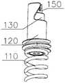
- FIG. 1is a schematic diagram of a three-dimensional structure of an integrated anchor provided by the first embodiment of the present invention.
- Figure 2is a side view of the integrated anchor in Figure 1.
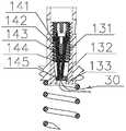
- Fig. 3is a three-dimensional exploded view of the integrated anchor in Fig. 1.
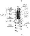
- Fig. 4is a cross-sectional view of an integrated anchoring element wearing an artificial tendon cord provided by the first embodiment of the present invention.
- Fig. 5is a cross-sectional view of an integrated anchor locking and cutting artificial tendons according to the first embodiment of the present invention.
- FIG. 6is a schematic diagram of a three-dimensional structure of an integrated anchor provided by the second embodiment of the present invention.
- Fig. 7is a cross-sectional view of the integrated anchor in Fig. 6.
- FIG. 8is a schematic diagram of a three-dimensional structure of an anchoring system provided by an embodiment of the present invention.
- Fig. 9is a cross-sectional view of the conveyor in Fig. 8.
- Fig. 10is a partial enlarged view of part M in Fig. 9.
- Fig. 11is a perspective exploded view of the conveyor in Fig. 8.
- Figure 12ais a structural schematic diagram of the lock buckle and the connecting position mating and docking.
- Figure 12bis a schematic diagram of the structure where the lock buckle and the connection position are separated.
- Fig. 12cis a schematic diagram of the structure when the sleeve protects the mating part of the base and the joint.
- Fig. 13ais a schematic diagram of the structure of the first snap ring and the second snap ring separated.
- Fig. 13bis a schematic diagram of the docking structure of the first snap ring and the second snap ring.
- Fig. 14is a schematic diagram of the three-dimensional structure of the handle part of the conveyor in Fig. 8.
- Figure 15is a schematic cross-sectional structure diagram of the integrated anchor installed in the conveyor.
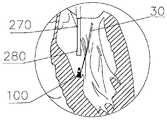
- Fig. 16is a schematic diagram of the anchoring system in the embodiment of the present invention being introduced into the left ventricle along the artificial chordae.
- Figure 17is a schematic diagram of the anchoring system reaching the left ventricle in an embodiment of the present invention.
- Fig. 18is a schematic diagram of the integrated anchoring member in the anchoring system in the embodiment of the present invention being anchored into the ventricular wall and locking the artificial chordae.
- Fig. 19is a schematic diagram of the withdrawal of the transporter from the left ventricle in the anchoring system in the embodiment of the present invention.
- orientation near the operatoris usually defined as the proximal end, and the orientation far away from the operator is defined as the distal end.
- the radial directionrefers to the direction along the diameter or radius
- the axial directionrefers to the direction along the central axis.
- the direction, the radial direction and the axial directionare perpendicular to each other
- the circumferential directionrefers to the circumferential direction around the central axis.
- the first embodiment of the present inventionprovides an integrated anchor 100, which includes an anchor portion 110, a base 120 fixedly connected to the proximal end of the anchor portion 110, and a base 120 installed on the base.
- the base 120is a hollow structure, and the lock core 140 is installed in the inner cavity 121 of the base 120.
- the base 120is cylindrical.
- the base 120has a diameter-reducing section 160 (as shown in FIG. 4).
- the diameter of the diameter-reducing section 160gradually decreases from its proximal end J to its distal end Y.
- the lock cylinder 140includes two oppositely arranged elastic arms 142, two
- the elastic arm 142is provided with a lock line structure 144 that cooperates with each other and a blade 143 provided at the proximal end of the lock line structure 144, and the artificial tendon 30 is inserted between the two elastic arms 142 (as shown in Figure 4);
- the elastic arm 142moves to the distal end relative to the diameter-reducing section 160 so that the diameter-reducing section 160 gradually squeezes the two elastic arms 142, and the locking wire structure 144 gradually merges from its distal end to its proximal end to lock the artificial chord 30 until the blade
- the part 143cuts the artificial chord 30 (as shown in FIG. 5).
- the diameter-reducing section 160may be directly arranged on the inner surface of the base 120, or by adding a lock shell 130, the diameter-reducing section 160 may be provided in the lock shell 130.
- the anchoring portion 110is used for anchoring into the tissue.
- the anchoring portion 110is a spiral nail, and the proximal end of the anchoring portion 110 and the base 120 are fixed by laser welding.
- the diameter reducing section 160is preferably a truncated cone hole.
- the artificial chord 30is preferably a medical suture, and other wires, threads, ropes, etc. that can be used as artificial chords can also be used.
- the integrated anchor 100 provided by the present inventionintegrates the functions of anchoring, locking and cutting the artificial tendon cord 30.
- the anchoring, locking and cutting operationscan be carried out by using the same conveyor, without the need to replace equipment, and the structure is simple and the operation is simple. Convenient, shorten the operation time and reduce the cost.
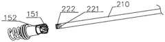
- the integrated anchor 100further includes a first snap ring 150, the first snap ring 150 is fixedly connected to the proximal end of the lock cylinder 140, and the first snap ring 150 includes a plurality of first centers arranged at intervals. 151 and a first bottom pointed groove 152 (as shown in FIG. 3) arranged between two adjacent first centers 151, the first center 151 faces the proximal end of the first snap ring 150, and the first bottom pointed groove 152 faces The distal end of the first snap ring 150.
- the proximal end of the first retaining ring 150 and the lock cylinder 140are fixed by laser welding.
- the first snap ring 150is used to connect with a driving device (such as the conveyor 200 described below). After the driving mechanism is connected to the first snap ring 150, the first snap ring 150 is driven to rotate and move to the distal end, thereby driving and The lock core 140 connected to the first snap ring 150 rotates and moves distally, so that the two elastic arms 142 of the lock core 140 move distally relative to the diameter reducing section 160 to realize the function of locking and cutting the artificial chord 30.
- a driving devicesuch as the conveyor 200 described below.
- the anchor portion 110, the base 120, the lock core 140, and the first snap ring 150are convenient for laser welding and can be used as implant materials, and they are all made of stainless steel.
- the proximal end of the base 120is provided with a connecting position 122 recessed into the base 120 and extending toward the distal end of the base 120 (as shown in FIG. 3).
- the contour shape of the connecting portion 122 along the axis from the proximal end to the distal end thereofis substantially a "Z" shape.
- the connecting position 122can be formed by cutting the proximal end of the base 120, and the outline shape of the connecting position 122 is roughly a "Z" shape.
- the driving mechanismis provided with a structure that is adapted to the connecting position 122. With this structure, when the driving mechanism is retracted backward, the connection with the connecting position 122 can be released without first moving in the direction perpendicular to the axial direction, and the operation is simple.
- the base 120also has a spiral section 170, the spiral section 170 is connected to the proximal end of the variable diameter section 160, the proximal end of the lock cylinder 140 is provided with a spiral seat 141, and the spiral seat 141 penetrates the spiral section 170.
- the inner and spiral seat 141is screwed to the spiral section 170; the rotation of the spiral seat 141 in the spiral section 170 causes the two elastic arms 142 to move distally relative to the diameter reducing section 160.
- the lock core 140rotates through the threads in the base 120 and moves to the distal end along the axial direction.
- the integrated anchor 100further includes a lock shell 130 (as shown in FIG. 1) fixedly inserted into the base 120, a variable diameter section 160 is provided at the distal end of the lock shell 130, and a spiral section 170 is opened in the lock housing 130 and communicates with the proximal end of the variable diameter section 160, and the minor diameter of the spiral section 170 is greater than or equal to the maximum diameter of the variable diameter section 160.
- the minor diameterrefers to the diameter of an imaginary cylinder tangent to the crest of the internal thread in the spiral section 170.
- the minor diameter of the spiral section 170is greater than or equal to the maximum diameter of the variable diameter section 160, so that when the elastic wall 142 does not enter the variable diameter
- the diameter section 160does not hinder the rotation and axial movement of the lock cylinder 140 in the spiral section 170.
- the variable diameter section 160 and the spiral section 170are opened in the lock housing 130.
- the variable diameter section 160 and the spiral section 170may be directly provided on the inner wall of the base 120.
- the lock shell 130 and the base 120are fixed by laser welding, and are made of materials that can be implanted in tissues, preferably stainless steel.
- the distal ends of the two elastic arms 142are provided with protrusions 145 protruding outwards.
- the protrusions 145 and the inner wall of the diameter reducing section 160Contact (as shown in Figure 5).
- the outer diameter of the boss 145is larger than the outer diameter of the two elastic arms 142, so that the boss 145 is squeezed when contacting the inner wall of the diameter reducing section 160, and the two elastic arms 142 The artificial tendon 30 is squeezed in the middle to lock and cut it.
- the lock line structure 144includes a plurality of smooth protrusions 1421 provided on one elastic wall 142 and a plurality of smooth protrusions 1421 provided on the other elastic wall 142, which are arranged opposite to and adapted to the plurality of protrusions 1421 Sleek depression 1422 (shown in Figure 3).
- the blade 143includes two blade tips arranged opposite to each other on the two elastic walls 142.
- the anchoring portion 110is a spiral nail.
- the distal end of the spiral nailhas a sharp tip 111 so that the spiral nail can be quickly anchored into the tissue.
- the proximal end of the outer peripheral surface of the base 120is provided with an external thread 123.
- the external thread 123is used to fit the driving device.
- the operation process of the integrated anchor 100 in this embodimentis as follows:
- the artificial tendon 30is put on the integrated anchor 100.
- the first snap ring 150is rotated forward, and the lock core 140 rotates along the same time.
- the boss 145 provided on the lock core 140contacts the frustum-shaped diameter reducing section 160 provided on the lock shell 130.
- the diameter reducing sectionThe conical surface of 160 will gradually squeeze the boss 145, so that the two opposite elastic arms 142 provided on the lock cylinder 140 will be elastically deformed, so that the two elastic walls 142 of the lock cylinder 140 are provided with a wave-shaped sleek lock with embedding concaves and convexes.
- the wire structure 144 and the opposite sharp blade 143gradually squeeze the artificial tendon 30, thereby locking and cutting the artificial tendon 30. Because the blade 143 provided on the lock core 140 is set more than the lock wire structure 144 It is far away from the proximal end of the boss 145, so the thread locking structure 144 squeezes the suture before the blade 143. After the thread locking structure 144 bites and locks the artificial tendon 30, continue to rotate the first snap ring 150 and the lock core 140, The blade 143 only begins to squeeze the artificial tendon 30 and finally cut the artificial tendon 30. It can be seen that the integrated anchor 100 in the present application integrates the functions of anchoring into the tissue, locking the artificial tendon cord, and cutting the artificial tendon cord. The structure is simple, and the locking of the artificial tendon cord and the cutting of the artificial tendon cord can be performed simultaneously. The operation is convenient and quick.
- the second embodiment of the present inventionprovides an integrated anchor 100a.
- the anchor portion 110 in the integrated anchor 100aincludes an anchor portion The main body 112 and the sub-anchor 113 arranged in the circumferential direction of the anchor body 112, and the distal end of the anchor body 112 is provided with a tip 111.
- the sub-anchor 113expands in the circumferential direction of the anchor body 112.
- the integrated anchor 100a in this embodimentdoes not need to be rotated in the process of anchoring into the tissue, and can be directly pushed into the tissue distally.
- an embodiment of the present inventionalso provides an anchoring system 10, which includes the integrated anchor 100 and the conveyor 200 described in any of the above embodiments.
- the conveyor 200includes at least a torsion component 203, a release component 202, and a locking and cutting component 201 (as shown in FIG. 11); the torsion component 203 cooperates with the release component 202, and the torsion component 203 is used for axial movement relative to the release component 202 So that the distal end of the release assembly 202 is connected to the base 120 of the integrated anchor 100 or released from the base 120 of the integrated anchor 100, and drives the release assembly 202 and the base 120 to rotate so as to connect with the base 120
- the anchoring portion 110 of the anchoris anchored into the target tissue; the locking and cutting assembly 201 is movably installed in the release assembly 202, and is connected with the integrated anchor 100 when the distal end of the release assembly 202 is connected to the base 120 of the integrated anchor 100
- the lock core 140is connected, and the lock cutting assembly 201 is used to drive the two elastic arms 142 of the lock core 120 to move distally relative to the diameter reducing section 160 to lock and cut the artificial tendon 30.
- the distal end of the release component 202is connected to the base 120 of the integrated anchor 100.
- the torsion component 203is relative to the release component 202 along the After moving axially to the proximal end, the distal end of the release assembly 202 is released from the base 120 of the integrated anchor 100.
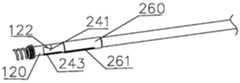
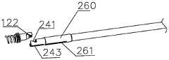
- the release assembly 202includes a release tube 230, and a joint 240 fixedly connected to the distal end of the release tube 230, and the joint 240 cooperates with the base 120 of the integrated anchor 100 (as shown in FIG. 12a);
- the torsion assembly 203includes a torsion tube 250 and a sleeve 260 fixedly connected to the distal end of the torsion tube 250; the release tube 230 is movably inserted in the torsion tube 250, the joint 240 is movably inserted in the sleeve 260, and the joint 240 and Limiting structures (243, 261) are provided between the sleeves 260 to limit the relative movement of the two in the axial direction; when the joint 240 is received in the sleeve 260, the joint 240 is connected to the base 120 of the integrated anchor 100, When the joint 240 is exposed to the outside of the sleeve 260, the joint 240 is released from the base 120 of the integrated anchor 100.
- the release tube 230adopts a metal hypotube, which has good compliance and can provide a good supporting force in the axial direction.
- the torsion tube 250adopts a metal hypotube, which has good compliance and torsion control. When the torsion tube 250 is rotated, the torsion force can be transmitted to the integrated anchor 100 at the maximum ratio, which improves the anchoring efficiency.
- the joint 240 and the release tube 230are both metal materials and can be fixed by laser welding.
- the sleeve 260 and the torsion tube 250are bonded and fixed by medical glue.
- the connector 240is a cylindrical hollow structure, and the distal end of the connector 240 is provided with a lock 241 recessed into the connector 240 and extending toward the proximal end of the connector 240.
- the outline shape of the lock catch 241 from the proximal end to the distal end thereof in the axial directionis substantially a "Z" shape.
- the shape of the lock 241matches the shape of the connection site 122 at the proximal end of the base 120 in the integrated anchor 100 (as shown in FIG. 12a). With this structure, when the conveyor 200 is directed The connection between the lock catch 241 and the connecting position 122 can be released by retreating, without first moving in the direction perpendicular to the axial direction, and the operation is simple.
- the lock catch 241may be formed by cutting the distal end of the circumferential surface 242 of the joint 240.
- the base 120 and the joint 240are relatively fixed, and vice versa.
- the joint 240can be relatively movable.
- the limiting structureincludes a rib 243 (as shown in FIG. 11) extending along the axial direction of the release tube 230 provided on the outer peripheral surface of the joint 240, and an upper edge provided on the wall of the sleeve 260
- the through groove 261 extending in the axial direction of the torsion tube 250 and the convex rib 243are adapted to the through groove 261.
- the limit structuremakes the torsion tube 250 and the release tube 230 only maintain relative axial movement and cannot rotate relative to each other. When the torsion tube 250 rotates, the release tube 230 rotates with the torsion tube 250.
- the locking and cutting assembly 201includes a locking and cutting tube 210 and a second retaining ring 220 fixedly connected to the distal end of the locking and cutting tube 210, the locking and cutting tube 210 is inserted in the release tube 230; the joint 240 and the integrated
- the second snap ring 220is connected to the lock core 140 of the integrated anchor 100, and the rotation of the lock cutting tube 210 drives the second snap ring 220 and the lock core 140 to rotate to drive the lock
- the two elastic arms 142 of the core 140move distally relative to the diameter reducing section 160; when the joint 240 and the base 120 of the integrated anchor 100 are released, the second snap ring 220 and the lock core 140 are released.
- the lock-cutting tube 210adopts a metal hypotube, which has good compliance and torsion control. When the lock-cutting tube 210 is rotated, the torsion force can be transmitted to the integrated anchor 100 at the maximum ratio, which improves the locking reliability.
- the distal end of the lock cylinder 140is provided with a first snap ring 150, and the first snap ring 150 is adapted to the second snap ring 220.
- the second snap ring 220includes a plurality of second centers 222 arranged at intervals and a second bottom tip groove provided between two adjacent second centers 222 221, the second center 222 faces the distal end of the second snap ring 220, and the second bottom tip groove 221 faces the proximal end of the second snap ring 220.
- the first center 151 and the second center 222are respectively formed by the intersection of two inclined surfaces. The inclined surfaces have a guiding effect, so that the first center 151 can be smoothly inserted into the second bottom tip groove 221, and the second center 222 can be smoothly inserted into the second bottom groove 221.
- a bottom tip groove 152is respectively formed by the intersection of two inclined surfaces. The inclined surfaces have a guiding effect, so that the first center 151 can be smoothly inserted into the second bottom tip groove 221, and the second center 222 can be smoothly inserted into the second bottom groove 221.
- the first snap ring 150 and the second snap ring 220are separated and connected.
- the first center 151 and the first bottom tip groove 152are provided on the first snap ring 150
- the second The second center point 222 and the second bottom point groove 221 provided on the snap ring 220have the same index on the circumference and are adapted to each other. Due to the guiding effect of the first center point 151 and the second center point 222, the first snap ring The 150 and the second snap ring 220 can be docked and separated at any angle and position in the circumferential direction. There is no need to deliberately align during the docking, and the docking can be realized by blind push, which saves time and effort.
- the first snap ring 150can be driven to rotate by rotating the lock cutting tube 210. Since the first snap ring 150 and the lock cylinder 140 are fixedly connected, the lock cylinder can be controlled. The rotation of 140 realizes locking and cutting off the artificial chordae.
- the integrated anchor 100further includes a handle 300 (as shown in FIG. 11); the torsion assembly 203 also includes a torsion tube base 350 fixedly connected to the proximal end of the torsion tube 250, and the release assembly 202 also includes The release tube base 340 fixedly connected to the proximal end of the release tube 230, and the locking and cutting assembly 201 further includes a knob 330 fixedly connected to the proximal end of the locking and cutting tube 210.
- the handle 300is provided with an axial limit groove 360, the torsion tube base 350 is slidably connected to the axial limit groove 360; the knob 330 extends out of the proximal end of the handle 300, and the knob 330 rotates to connect to the handle 330
- the release tube base 340is fixed in the handle 300 and is located between the torsion tube base 350 and the knob 330.
- the handle 300includes a handle shell 320, and the axial limiting groove 360 is axially opened on the handle shell 320. Rotating the knob 330 can drive the lock cutting tube 210 to rotate, which in turn drives the second snap ring 220 to rotate.
- an operating member 310is further provided on the handle 300, the operating member 310 passes through the axial limiting groove 360 and is rotatably connected to the torsion tube base 350.
- the torsion tube base 350is provided with a pin hole 351 (as shown in FIG. 10), and the operating member 310 includes a connecting member 311 inserted into the pin hole 351, that is, the operating member 310 and the torsion tube base 350
- the pin hole 351 and the connecting member 311are rotationally connected.
- the proximal end of the axial limiting groove 360communicates with a vertical stopping groove 370 (as shown in FIG. 14); the movement of the operating member 310 along the axial limiting groove 360 drives the torsion tube base 350 to move in the axial direction, and the operating member 310 rotates into the stop groove 370 to define the axial position of the torsion tube base 350.
- the torsion tube base 350when the operating member 310 is moved proximally along the axial limit groove 360, the torsion tube base 350 can be driven to move proximally in the axial direction, and the torsion tube 250 and the sleeve 260 can be driven to move proximally.
- the torsion tube base 350can be driven to move to the distal end in the axial direction, thereby driving the torsion tube 250 and the sleeve 260 to the distal end Move to protect the joint 240 in the sleeve 260.
- the operating member 310is rotated into the stop groove 370 to define the axial position of the torsion tube base 350, so that the joint 240 is kept in the sleeve 260.
- rotating the handle housing 320can drive the torsion base 350 connected with the handle housing 320 to rotate, thereby driving the torsion tube 250 and the sleeve 260 to rotate. Since the sleeve 260 and the joint 240 have a limiting structure, The joint 240 can follow the sleeve 260 to rotate, and then can drive the integrated anchor 100 connected to the joint 240 to rotate, so that the anchor portion 110 of the integrated anchor 100 is screw anchored into the tissue to complete the anchoring operation.
- the integrated anchor 100further includes a support assembly 204 (as shown in FIG. 11).
- the support assembly 204includes a support tube 270, connected to the proximal end of the support tube 270 and movably sleeved on the distal end of the handle 300.
- the reinforcing tube 360 on the end and the sheath 280fixedly connected to the distal end of the support tube 270, the torsion tube 250 is movably inserted in the support tube 270 and the reinforcement tube 360, and the sleeve 260 is movably inserted in the sheath 280.
- the support tube 270adopts a polymer material composite tube with a braided mesh structure, which has good compliance performance and can be pushed freely in a tortuous lumen, and can provide a better supporting force in the axial direction.
- the sheath 280surrounds the tip of the spiral portion 110 of the integrated anchor 100, so that the integrated anchor 100 can be smoothly pushed along the outer sheath without scraping the inner wall of the outer sheath; the sheath 280 also It can protect the native chordae and avoid scratching or even cutting the chordae when the integrated anchor 100 is screwed into the myocardial tissue.
- the sheath 280is a rigid material, which can provide a good supporting force when the integrated anchor 100 penetrates the myocardial tissue, so as to improve the anchoring accuracy.
- a limiting ribis provided between the proximal end of the reinforced tube 360 and the distal end of the handle 300, and the two limiting ribs partially overlap in the radial direction.
- an internal thread 281is provided in the sheath 280.
- the internal thread 281 in the sheath 280fits with the external thread 123 outside the base 120 in the integrated anchor 100 (as shown in FIG. 15).
- the sheath 280 and the base 120are screwed and transmitted, so that the conveyor 200 can stably support the integrated anchor 100.
- the assembly process of the anchoring system 10 in this embodimentis as follows:
- the integrated anchor 100is first loaded into the conveyor 200, specifically, the reinforcing tube 360 is driven to move proximally to expose the sleeve 260, and then the operating member 310 is driven to move proximally.
- the torsion component 203moves proximally to expose the joint 240, and the joint 240 is docked with the base 120 of the integrated anchor 110, the first snap ring 150 and the second snap ring 220 are docked, and then push to the distal end in turn.
- the member 310drives the torsion assembly 203 to move distally so that the sleeve 260 covers the joint 240 and the base 120 of the integrated anchor 100, and the reinforcing tube 360 is driven distally so that the sheath 280 covers the integrated anchor 100
- the distal end; finally, the free end of the artificial chord 30 (the artificial chord 30 has been sewn to the valve leaflet) extending out of the bodyis passed through the integrated anchor 100 and the lock cutting tube 210 in turn, until the proximal end of the knob 330 Pierce out.
- the working process of the anchoring system 10 in this embodimentis as follows:
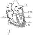
- the transporter 200is introduced into the left ventricle LV along the artificial chordae 30.
- the handle housing 320is first rotated and the torsion assembly 203 connected to the handle housing 320 rotates.
- There is a sleeve 260 and a joint 240 between The axial limit structuremakes the joint 240 rotate together with the sleeve 260, thereby rotating the integrated anchor 100 connected to the joint 240, so that the anchor portion 110 of the integrated anchor 100 is anchored during the rotation.
- On the papillary muscle 40(as shown in Figure 18).
- the driving knob 330is then rotated to make the integrated anchor member 100 lock the artificial tendon cord 30 and cut the artificial tendon cord 30.
- the driving operating member 310is moved back in the axial direction to expose the joint 240 from the sleeve 260.
- the handle housing 320 and the support rod 360are driven to withdraw the corresponding pipe bodies and the parts connected with the pipe bodies to the outside of the body.
Landscapes
- Health & Medical Sciences (AREA)
- Life Sciences & Earth Sciences (AREA)
- Veterinary Medicine (AREA)
- Animal Behavior & Ethology (AREA)
- Engineering & Computer Science (AREA)
- Biomedical Technology (AREA)
- Heart & Thoracic Surgery (AREA)
- Cardiology (AREA)
- Public Health (AREA)
- Surgery (AREA)
- General Health & Medical Sciences (AREA)
- Molecular Biology (AREA)
- Nuclear Medicine, Radiotherapy & Molecular Imaging (AREA)
- Medical Informatics (AREA)
- Oral & Maxillofacial Surgery (AREA)
- Transplantation (AREA)
- Vascular Medicine (AREA)
- Prostheses (AREA)
Abstract
Description
Translated fromChinese本发明涉及医疗器械技术领域,具体涉及一种集成式锚定件及锚定系统。The invention relates to the technical field of medical devices, in particular to an integrated anchoring piece and an anchoring system.
在治疗二尖瓣反流(mitral regurgitation,MR)的修复手术中,传统外科手术创伤大、风险高,现在临床上对微创修复二尖瓣反流的手术有很大的需求。二尖瓣反流介入微创治疗技术具有创伤小、并发症少等优势。人工腱索植入是介入式二尖瓣修复术的一种,其手术原理是:将缝线经导管途径送入左心室,使得缝线的一端与二尖瓣瓣叶固定,缝线的另一端通过锚钉与左心室心肌壁或乳头肌连接,形成人工腱索。但目前还存在着以下技术问题:人工腱索植入所用到的锚钉功能单一,一般仅用于锚入心室壁或乳头肌,后续还需要导入额外的器械将人工腱索与锚钉锁紧、以及导入额外的器械将人工腱索切断,即使用现有的锚钉实施经导管途径腱索修复时,锚钉的锚入、人工腱索与锚钉的锁紧、人工腱索的切断分别需要单独的器械实施,因此手术过程中需要更换及导入不同的器械,操作较复杂,需使用的器械数量较多,成本较高。In the treatment of mitral regurgitation (mitral regurgitation, MR) repair surgery, traditional surgical procedures are traumatic and high-risk. Nowadays, there is a great demand for minimally invasive mitral regurgitation surgery in clinical practice. Interventional minimally invasive treatment of mitral regurgitation has the advantages of less trauma and fewer complications. Artificial chordal implantation is a kind of interventional mitral valve repair. The operating principle is: the suture is fed into the left ventricle through the catheter, so that one end of the suture is fixed to the mitral valve leaflet, and the other suture One end is connected with the left ventricular myocardial wall or papillary muscle through an anchor to form an artificial chordae. However, there are still the following technical problems: the anchors used for artificial chordal implantation have a single function, and are generally only used to anchor the ventricular wall or papillary muscles. Later, additional instruments need to be introduced to lock the artificial chords and anchors. , And introduce additional equipment to cut the artificial tendon, that is, when the existing anchor is used for transcatheter tendon repair, the anchoring of the anchor, the locking of the artificial tendon and the anchor, and the cutting of the artificial tendon are respectively Separate instruments are required for implementation. Therefore, different instruments need to be replaced and introduced during the operation. The operation is more complicated, the number of instruments to be used is large, and the cost is higher.
发明内容Summary of the invention
为解决上述技术问题,本申请一方面提供一种集成式锚定件。In order to solve the above technical problems, one aspect of the present application provides an integrated anchor.
具体技术方案为:一种集成式锚定件,包括锚定部、固定连接所述锚定部的近端的基座、及装设于所述基座内的锁芯;所述基座内具有变径段,所述变径段的直径自其近端向其远端逐渐减小,所述锁芯包括相对设置的两弹性臂,所述两弹性臂上设有相互配合的锁线结构及设于所述锁线结构的近端的刃部,人工腱索穿装在所述两弹性臂之间;所述两弹性臂相对所述变径段向远端移动使得所述变径段逐渐挤压所述两弹性臂,所述锁线结构自其远端至其近端逐渐对合以锁紧所述人工腱索,直至所述刃部切断所述人工腱索。The specific technical solution is: an integrated anchor, including an anchor portion, a base fixedly connected to the proximal end of the anchor portion, and a lock core installed in the base; There is a variable-diameter section, the diameter of the variable-diameter section gradually decreases from its proximal end to its distal end, the lock core includes two oppositely arranged elastic arms, and the two elastic arms are provided with a lock wire structure that cooperates with each other And the blade portion provided at the proximal end of the lock wire structure, the artificial tendon is inserted between the two elastic arms; the two elastic arms move distally relative to the diameter-changing section so that the diameter-changing section gradually squeezes By pressing the two elastic arms, the wire locking structure gradually merges from its distal end to its proximal end to lock the artificial chords until the blade cuts the artificial chords.
本申请另一方面提供一种锚定系统。Another aspect of the present application provides an anchoring system.
具体技术方案为:一种锚定系统,包括如上述的集成式锚定件及输送器;所述输送器至少包括扭转组件、解脱组件、及锁切组件;所述扭转组件与所述解脱组件配合,所述扭转组件用于相对所述解脱组件做轴向移动以使得所述解脱组件的远端连接所述集成式锚定件的基座或与所述集成式锚定件的基座解脱,以及带动所述解脱组件及所述基座旋转以使得与所述基座连接的集成式锚定部锚入目标组织;所述锁切组件活动穿装在所述解脱组件内,并在所述解脱组件的远端连接所述集成式锚定件的基座时与所述集成式锚定件的锁芯连接,所述锁切组件用于驱动所述锁芯的两弹性臂相对所述变径段向远端移动,以锁紧及切断所述人工腱索。The specific technical solution is: an anchoring system, including the above-mentioned integrated anchor and a conveyor; the conveyor at least includes a torsion component, a release component, and a locking and cutting component; the torsion component and the release component In cooperation, the torsion component is used to move axially relative to the release component so that the distal end of the release component is connected to the base of the integrated anchor or released from the base of the integrated anchor , And drive the release assembly and the base to rotate so that the integrated anchoring portion connected with the base is anchored into the target tissue; the locking and cutting assembly is movably installed in the release assembly and placed in the When the distal end of the release assembly is connected to the base of the integrated anchor, it is connected to the lock core of the integrated anchor, and the lock and cut assembly is used to drive the two elastic arms of the lock core relative to the The variable diameter section moves to the distal end to lock and cut the artificial chordae.
本申请的有益效果:本申请提供的集成式锚定件,设置有锚定部、固定连接锚定部的近端的基座、及装设于基座内的锁芯,基座内具有变径段,变径段的直径自其近端向其远端逐渐减小,锁芯上的两弹性臂上设有相互配合的锁线结构及设于锁线结构的近端的刃部,人工腱索穿装在两弹性臂之间;两弹性臂相对变径段向远端移动使得变径段逐渐挤压两弹性臂,锁线结构自其远端至其近端逐渐对合以锁紧人工腱索,直至刃部切断人工腱索,即本申请的集成式锚定件集成了锚定、锁紧以及切断人工腱索的功能,而本申请中的锚定系统中的输送器中具有扭转组件、解脱组件、及锁切组件,三者相互协作,将本申请的集成式锚定件应用于介入式人工腱索植入术时,仅需通过一个本发明中的输送器便可完成导入锚钉、锚定、锁紧人工腱索及切断人工腱索的操作,从而简化了操作步骤,减少了器械数量,降低了成本。The beneficial effects of the present application: the integrated anchor provided by the present application is provided with an anchoring part, a base fixedly connected to the proximal end of the anchoring part, and a lock core installed in the base. Diameter section, the diameter of the variable diameter section gradually decreases from its proximal end to its distal end. The two elastic arms on the lock cylinder are provided with a matching lock wire structure and a blade located at the proximal end of the lock wire structure. The tendon is inserted between the two elastic arms; the two elastic arms move to the distal end relative to the variable diameter section, so that the variable diameter section gradually squeezes the two elastic arms, and the locking wire structure gradually merges from the distal end to the proximal end to lock the artificial tendon The artificial tendon cord is cut up to the blade, that is, the integrated anchor of the present application integrates the functions of anchoring, locking and cutting the artificial tendon cord, while the conveyor in the anchoring system of the present application has a torsion component , Release component, and lock cutting component, the three cooperate with each other. When the integrated anchor of the present application is applied to the interventional artificial chordal implant surgery, only one conveyor of the present invention can be used to complete the introduction of the anchor The operation of nailing, anchoring, locking the artificial tendon cord and cutting off the artificial tendon cord, thereby simplifying the operation steps, reducing the number of instruments and reducing the cost.
为了更清楚地说明本发明实施例中的技术方案,下面将对实施例中所需要使用的附图作简单地介绍,显而易见地,下面描述中的附图仅仅是本发明的一些实施例,对于本领域普通技术人员来讲,在不付出创造性劳动性的前提下,还可以根据这些附图获得其他的附 图。In order to explain the technical solutions in the embodiments of the present invention more clearly, the following will briefly introduce the drawings that need to be used in the embodiments. Obviously, the drawings in the following description are only some embodiments of the present invention. For those of ordinary skill in the art, without creative labor, other drawings can be obtained from these drawings.
图1为本发明第一实施例提供的一种集成式锚定件的立体结构示意图。FIG. 1 is a schematic diagram of a three-dimensional structure of an integrated anchor provided by the first embodiment of the present invention.
图2为图1中集成式锚定件的侧视图。Figure 2 is a side view of the integrated anchor in Figure 1.
图3为图1中集成式锚定件的立体分解图。Fig. 3 is a three-dimensional exploded view of the integrated anchor in Fig. 1.
图4为本发明第一实施例提供的一种集成式锚定件穿装人工腱索的剖面图。Fig. 4 is a cross-sectional view of an integrated anchoring element wearing an artificial tendon cord provided by the first embodiment of the present invention.
图5为本发明第一实施例提供的一种集成式锚定件锁紧及切断人工腱索的剖面图。Fig. 5 is a cross-sectional view of an integrated anchor locking and cutting artificial tendons according to the first embodiment of the present invention.
图6为本发明第二实施例提供的一种集成式锚定件的立体结构示意图。6 is a schematic diagram of a three-dimensional structure of an integrated anchor provided by the second embodiment of the present invention.
图7为图6中集成式锚定件的剖面图。Fig. 7 is a cross-sectional view of the integrated anchor in Fig. 6.
图8为本发明实施例提供的一种锚定系统的立体结构示意图。FIG. 8 is a schematic diagram of a three-dimensional structure of an anchoring system provided by an embodiment of the present invention.
图9为图8中输送器的剖面图。Fig. 9 is a cross-sectional view of the conveyor in Fig. 8.
图10为图9中M部分的局部放大图。Fig. 10 is a partial enlarged view of part M in Fig. 9.
图11为图8中输送器的立体分解图。Fig. 11 is a perspective exploded view of the conveyor in Fig. 8.
图12a为锁扣和连接位配合对接的结构示意图。Figure 12a is a structural schematic diagram of the lock buckle and the connecting position mating and docking.
图12b为锁扣和连接位分开的结构示意图。Figure 12b is a schematic diagram of the structure where the lock buckle and the connection position are separated.
图12c为套筒将基座和接头配合处护住时的结构示意图。Fig. 12c is a schematic diagram of the structure when the sleeve protects the mating part of the base and the joint.
图13a为第一卡环和第二卡环分离的结构示意图。Fig. 13a is a schematic diagram of the structure of the first snap ring and the second snap ring separated.
图13b为第一卡环和第二卡环对接的结构示意图。Fig. 13b is a schematic diagram of the docking structure of the first snap ring and the second snap ring.
图14为图8中输送器中手柄部分的立体结构示意图。Fig. 14 is a schematic diagram of the three-dimensional structure of the handle part of the conveyor in Fig. 8.
图15为将集成式锚定件安装在输送器中的剖面结构示意图。Figure 15 is a schematic cross-sectional structure diagram of the integrated anchor installed in the conveyor.
图16为本发明实施例中的锚定系统沿人工腱索导入左心室的示意图。Fig. 16 is a schematic diagram of the anchoring system in the embodiment of the present invention being introduced into the left ventricle along the artificial chordae.
图17为本发明实施例中的锚定系统达到左心室的示意图。Figure 17 is a schematic diagram of the anchoring system reaching the left ventricle in an embodiment of the present invention.
图18为本发明实施例中的锚定系统中集成式锚定件锚入心室壁并锁紧人工腱索的示意图。Fig. 18 is a schematic diagram of the integrated anchoring member in the anchoring system in the embodiment of the present invention being anchored into the ventricular wall and locking the artificial chordae.
图19为本发明实施例中的锚定系统中输送器撤出左心室的示意图。Fig. 19 is a schematic diagram of the withdrawal of the transporter from the left ventricle in the anchoring system in the embodiment of the present invention.
下面将结合本发明实施例中的附图,对本发明实施例中的技术方案进行清楚、完整地描述,显然,所描述的实施例仅是本发明一部分实施例,而不是全部的实施例。基于本发明中的实施例,本领域普通技术人员在没有做出创造性劳动前提下所获得的所有其他实施例,都属于本发明保护的范围。The following will clearly and completely describe the technical solutions in the embodiments of the present invention with reference to the accompanying drawings in the embodiments of the present invention. Obviously, the described embodiments are only a part of the embodiments of the present invention, rather than all the embodiments. Based on the embodiments of the present invention, all other embodiments obtained by those of ordinary skill in the art without creative work shall fall within the protection scope of the present invention.
本发明的说明书和权利要求书及所述附图中的术语“第一”、“第二”等是用于区别不同对象,而不是用于描述特定顺序。此外,术语“包括”和“具有”以及它们任何变形,意图在于覆盖不排他的包含。例如包含了一系列步骤或单元的过程、方法、系统、产品或设备没有限定于已列出的步骤或单元,而是可选地还包括没有列出的步骤或单元,或可选地还包括对于这些过程、方法、产品或设备固有的其它步骤或单元。The terms "first", "second", etc. in the specification and claims of the present invention and the drawings are used to distinguish different objects, rather than to describe a specific sequence. In addition, the terms "including" and "having" and any variations of them are intended to cover non-exclusive inclusions. For example, a process, method, system, product, or device that includes a series of steps or units is not limited to the listed steps or units, but optionally includes unlisted steps or units, or optionally also includes Other steps or units inherent to these processes, methods, products or equipment.
在本文中提及“实施例”意味着,结合实施例描述的特定特征、结构或特性可以包含在本发明的至少一个实施例中。在说明书中的各个位置出现该短语并不一定均是指相同的实施例,也不是与其它实施例互斥的独立的或备选的实施例。本领域技术人员显式地和隐式地理解的是,本文所描述的实施例可以与其它实施例相结合。Reference to "embodiments" herein means that a specific feature, structure, or characteristic described in conjunction with the embodiments may be included in at least one embodiment of the present invention. The appearance of the phrase in various places in the specification does not necessarily refer to the same embodiment, nor is it an independent or alternative embodiment mutually exclusive with other embodiments. Those skilled in the art clearly and implicitly understand that the embodiments described herein can be combined with other embodiments.
方位定义:在医疗器械技术领域,通常将靠近操作者的方位定义为近端,远离操作者的方位定义为远端,径向是指沿直径或半径的方向,轴向是指沿中心轴线的方向,径向与轴向相互垂直,周向是指绕中心轴线的圆周方向。除非另有定义,本发明所使用的所有的技术和科学术语与属于本发明的技术领域的技术人员通常理解的含义相同。本发明在说明书中所使用的惯用术语只是为了描述具体实施例的目的,并不能理解为对本发明的限制。Definition of orientation: In the field of medical device technology, the orientation near the operator is usually defined as the proximal end, and the orientation far away from the operator is defined as the distal end. The radial direction refers to the direction along the diameter or radius, and the axial direction refers to the direction along the central axis. The direction, the radial direction and the axial direction are perpendicular to each other, and the circumferential direction refers to the circumferential direction around the central axis. Unless otherwise defined, all technical and scientific terms used in the present invention have the same meaning as commonly understood by those skilled in the technical field of the present invention. The conventional terms used in the specification of the present invention are only for the purpose of describing specific embodiments, and should not be construed as limiting the present invention.
如图1至图5所示,本发明第一实施例提供一种集成式锚定件100,包括锚定部110、固定连接锚定部110的近端的基座120、及装设于基座120内的锁芯140。所述基座120为中空结构,所述锁芯140装设于所述基座120的内腔121中。在本实施例中,所述基座120为圆筒形。As shown in FIGS. 1 to 5, the first embodiment of the present invention provides an
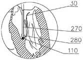
基座120内具有变径段160(如图4所示),变径段160的直径自其近端J向其远端Y逐渐减 小,锁芯140包括相对设置的两弹性臂142,两弹性臂142上设有相互配合的锁线结构144及设于锁线结构144的近端的刃部143,人工腱索30穿装在两弹性臂142之间(如图4所示);两弹性臂142相对变径段160向远端移动使得变径段160逐渐挤压两弹性臂142,锁线结构144自其远端至其近端逐渐对合以锁紧人工腱索30,直至刃部143切断人工腱索30(如图5所示)。The
其中所述变径段160可直接设置在所述基座120的内表面,也可以通过增加一个锁壳130,在锁壳130内设置变径段160。The diameter-reducing
锚定部110用于锚入组织内,在本实施例中,锚定部110为螺旋钉,锚定部110的近端与基座120采用激光焊接固定。所述变径段160优选为锥台孔。人工腱索30优选医用缝线,其它可用作人工腱索的丝、线、绳等也可采用。The anchoring
本发明提供的集成式锚定件100集锚定、锁紧以及切断人工腱索30功能为一体,使用同一输送器即可实施锚定、锁紧及切断操作,无需更换器械,结构简单、操作便捷,缩短手术时间,降低成本。The
在进一步的实施例中,集成式锚定件100还包括第一卡环150,第一卡环150与锁芯140的近端固定连接,第一卡环150包括多个间隔设置的第一顶尖151以及设于相邻两个第一顶尖151之间的第一底尖槽152(如图3所示),第一顶尖151朝向第一卡环150的近端,第一底尖槽152朝向第一卡环150的远端。本实施例中,第一卡环150与锁芯140的近端采用激光焊接固定。In a further embodiment, the
第一卡环150用于与驱动器械(如下面所述的输送器200)连接,驱动机械与第一卡环150连接后,驱动第一卡环150旋转并向远端移动,进而可以带动与第一卡环150连接的锁芯140旋转并向远端移动,以使锁芯140的两弹性臂142相对变径段160向远端移动,进而实现锁紧以及切断人工腱索30功能。The
在本实施例中,所述锚定部110、基座120、锁芯140以及第一卡环150为便于激光焊接,且能作为植入材料,均优选不锈钢材质。In this embodiment, the
在进一步的实施例中,基座120的近端设有向基座120内凹陷并向基座120的远端延伸的 连接位122(如图3所示)。In a further embodiment, the proximal end of the
在进一步的实施例中,连接位122沿轴自其近端向远端的轮廓形状大致呈“Z”形。In a further embodiment, the contour shape of the connecting
本实施例中,所述连接位122可通过切割基座120近端形成,连接位122的轮廓形状大致呈“Z”形,驱动机械中设有与所述连接位122适配的结构,采用这种结构,当驱动机械向后撤即可解除与连接位122的连接,无需先在垂直于轴向的方向移动,操作简单。In this embodiment, the connecting
在进一步的实施例中,基座120内还具有螺旋段170,螺旋段170连通变径段160的近端,锁芯140的近端设有螺旋座141,螺旋座141穿装于螺旋段170内且螺旋座141与螺旋段170螺接;螺旋座141于螺旋段170内的旋转使得两弹性臂142相对变径段160向远端移动。在本实施例中,锁芯140在基座120内通过螺纹进行旋转并沿轴向向远端移动。In a further embodiment, the
在进一步的实施例中,集成式锚定件100还包括固定穿装于基座120内的锁壳130(如图1所示),变径段160开设在锁壳130的远端,螺旋段170开设在锁壳130内并连通变径段160的近端,螺旋段170的小径大于或等于变径段160的最大直径。其中所述小径是指与螺旋段170中的内螺纹牙顶相切的假想圆柱的直径,将螺旋段170的小径大于或等于变径段160的最大直径,以使当弹性壁142未进入变径段160时不阻碍锁芯140在螺旋段170内旋转及轴向移动。在本实施例中,所述变径段160和螺旋段170开设在锁壳130内。在其他实施例中,所述变径段160和螺旋段170可直接开设在基座120的内壁上。所述锁壳130与所述基座120采用激光焊接固定,且采用能作为植入组织内的材料,优选采用不锈钢材质。In a further embodiment, the
在进一步的实施例中,两弹性臂142的远端设有向外突出的凸台145,当两弹性臂142相对变径段160向远端移动时,凸台145与变径段160的内壁接触(如图5所示)。在本实施例中,所述凸台145的外径大于所述两弹性臂142的外径,使得凸台145在与变径段160的内壁接触时被挤压,进而使两弹性臂142向中间挤压位于其中的人工腱索30,以将其锁住和切断。In a further embodiment, the distal ends of the two
在进一步的实施例中,锁线结构144包括设于一弹性壁142上的数个圆滑的凸起1421及设于另一弹性壁142上与数个凸起1421相对设置并适配的数个圆滑的凹陷1422(如图3所示)。当两弹性臂142被挤压时,凸起1421置于凹陷1422中,使得两弹性臂142相互咬合。刃部143 包括于两弹性壁142上相对设置的两个刃尖。In a further embodiment, the
在进一步的实施例中,锚定部110为螺旋钉。所述螺旋钉的远端具有尖锐的尖端111,以使螺旋钉能够快速的锚入组织中。基座120的外周面的近端上设有外螺纹123。所述外螺纹123用于与驱动器械适配,当旋转集成式锚定件100使得锚定部110锚入组织时,驱动器械与所述外螺纹123之间的螺接结构能够为锚定部110提供支撑。In a further embodiment, the anchoring
本实施例中的集成式锚定件100的操作过程如下:The operation process of the
如图4和图5所示,人工腱索30穿装在集成式锚定件100中,在锚定部110锚入组织后,正向旋转第一卡环150,锁芯140旋转的同时沿轴向向远端移动,直至锁芯140上设有的凸台145和锁壳130上设有的锥台型的变径段160接触,随着锁芯140逐渐向远端移动,变径段160的圆锥面会逐渐挤压凸台145,使锁芯140上设有的两相对的弹性臂142发生弹性变形,使锁芯140的两弹性壁142上设置的凹凸相嵌的波浪形的圆滑锁线结构144和相对设置的尖锐的刃部143逐渐挤压人工腱索30,从而将人工腱索30锁紧和剪断,由于锁芯140上设有的刃部143设置在比锁线结构144更远离凸台145的近端,所以锁线结构144比刃部143先挤压缝线,当锁线结构144咬合锁固住人工腱索30后,继续旋转第一卡环150及锁芯140,刃部143才开始挤压人工腱索30并最终将人工腱索30剪断。可见本申请中的集成式锚定件100将锚入组织、锁固人工腱索及切断人工腱索的功能集成于一体,结构简单,且锁固人工腱索与切断人工腱索可同步进行,操作方便快捷。As shown in Figures 4 and 5, the
如图6和图7所示,本发明第二实施例提供一种集成式锚定件100a,与第一实施例不同的是,集成式锚定件100a中的锚定部110包括锚定部本体112以及沿锚定部本体112周向设置的子锚定件113,所述锚定部本体112的远端设有尖端111。子锚定件113沿锚定部本体112周向展开。本实施例中的集成式锚定件100a在锚入组织的过程中无需旋转,可直接向远端推进组织中。As shown in FIGS. 6 and 7, the second embodiment of the present invention provides an
如图8至图11所示,本发明实施例还提供一种锚定系统10,包括如上面任一项实施例所述的集成式锚定件100及输送器200。As shown in FIGS. 8 to 11, an embodiment of the present invention also provides an
其中,输送器200至少包括扭转组件203、解脱组件202、及锁切组件201(如图11所示);扭转组件203与解脱组件202配合,扭转组件203用于相对解脱组件202做轴向移动以使得解脱组件202的远端连接集成式锚定件100的基座120或与集成式锚定件100的基座120解脱,以及带动解脱组件202及基座120旋转以使得与基座120连接的锚定部110锚入目标组织;锁切组件201活动穿装在解脱组件202内,并在解脱组件202的远端连接集成式锚定件100的基座120时与集成式锚定件100的锁芯140连接,锁切组件201用于驱动锁芯120的两弹性臂142相对变径段160向远端移动,以锁紧及切断人工腱索30。Wherein, the
在本实施例中,当扭转组件203相对解脱组件202沿轴向向远端移动后,解脱组件202的远端连接集成式锚定件100的基座120,当扭转组件203相对解脱组件202沿轴向向近端移动后,解脱组件202的远端与集成式锚定件100的基座120解脱。In this embodiment, when the
在进一步的实施例中,解脱组件202包括解脱管230、以及固定连接解脱管230的远端的接头240,接头240与集成式锚定件100的基座120配合(如图12a所示);扭转组件203包括扭转管250、以及固定连接于扭转管250的远端的套筒260;解脱管230活动穿设于扭转管250中,接头240活动穿设在套筒260内,且接头240与套筒260之间设有限位结构(243、261)以限定二者在轴向上相对移动;接头240被收入套筒260内时,接头240与集成式锚定件100的基座120连接,接头240被暴露于套筒260外时,接头240与集成式锚定件100的基座120解脱。In a further embodiment, the
所述解脱管230采用金属海波管,具有良好的顺应性并在轴向能提供较好的支撑力。扭转管250采用金属海波管,具有良好的顺应性和扭控性,旋转扭转管250时保证扭转力能最大比的传递到集成式锚定件100,提高锚定效率。The
在本实施例中,所述接头240与所述解脱管230均为金属材料,可以通过激光焊接固定。所述套筒260与扭转管250采用医用胶水粘接固定。In this embodiment, the joint 240 and the
在进一步的实施例中,接头240为圆柱中空结构,接头240的远端的设有向接头240内凹陷并向接头240的近端延伸的锁扣241。In a further embodiment, the
在进一步的实施例中,锁扣241沿轴向自其近端向远端的轮廓形状大致呈“Z”形。所述锁扣241的形状与所述集成式锚定件100中的基座120近端的连接位122的形状相适配(如图12a所示),采用这种结构,当输送器200向后撤即可解除锁扣241与连接位122的连接,无需先在垂直于轴向的方向移动,操作简单。所述锁扣241可以是将接头240的圆周面242的远端切割形成。In a further embodiment, the outline shape of the
如图12a至图12c所示,当锁扣241和连接位122配合并当套筒260将基座120和接头240配合处护住时,基座120和接头240相对固定,反之基座120和接头240可以相对活动。As shown in Figures 12a to 12c, when the
在进一步的实施例中,限位结构包括设于接头240的外周面上沿解脱管230的轴向延伸的凸筋243(如图11所示),以及开设于套筒260的筒壁上沿扭转管250的轴向延伸的通槽261,凸筋243与通槽261适配。限位结构使得扭转管250与解脱管230只能保持相对轴向运动,不能相对旋转,当扭转管250旋转时,解脱管230跟随扭转管250旋转。In a further embodiment, the limiting structure includes a rib 243 (as shown in FIG. 11) extending along the axial direction of the
在进一步的实施例中,锁切组件201包括锁切管210以及固定连接于锁切管210的远端的第二卡环220,锁切管210穿设在解脱管230内;接头240与集成式锚定件100的基座120连接时,第二卡环220连接集成式锚定件100的锁芯140,锁切管210的旋转带动第二卡环220及锁芯140旋转,以驱动锁芯140的两弹性臂142相对变径段160向远端移动;接头240与集成式锚定件100的基座120解脱时,第二卡环220与锁芯140解脱。In a further embodiment, the locking and cutting
锁切管210采用金属海波管,具有良好的顺应性和扭控性,旋转锁切管210时保证扭转力能最大比的传递到集成式锚定件100,提高锁紧可靠性。The lock-cutting
如图13a和图13b所示,在本实施例中,锁芯140的远端设有第一卡环150,所述第一卡环150与第二卡环220相适配。As shown in FIGS. 13a and 13b, in this embodiment, the distal end of the
如图11和图13a所示,在进一步的实施例中,第二卡环220包括多个间隔设置的第二顶尖222以及设于相邻两个第二顶尖222之间的第二底尖槽221,第二顶尖222朝向第二卡环220的远端,第二底尖槽221朝向第二卡环220的近端。所述第一顶尖151和第二顶尖222分别由两斜面相交形成,斜面具有导向作用,而使第一顶尖151能够顺利的插入第二底尖槽221, 以及使第二顶尖222顺利的插入第一底尖槽152中。As shown in FIGS. 11 and 13a, in a further embodiment, the
如图13a和图13b所示,为第一卡环150和第二卡环220分离和对接状态视图,第一卡环150上设有的第一顶尖151和第一底尖槽152、第二卡环220上设有的第二顶尖222和第二底尖槽221由于在圆周上具有相同的分度并相互适配,由于第一顶尖151和第二顶尖222的导向作用,第一卡环150和第二卡环220可以在周向上的任意角度、任意位置实现对接和分离,对接时不必刻意对准,通过盲推即可以实现对接,省时省力。当第一卡环150和第二卡环220形成对接后,可以通过旋转锁切管210来驱动第一卡环150旋转,由于第一卡环150和锁芯140固定连接,因此可以控制锁芯140的旋转,从而实现锁紧以及切断人工腱索。As shown in Figures 13a and 13b, the
在进一步的实施例中,集成式锚定件100还包括手柄300(如图11所示);扭转组件203还包括固定连接于扭转管250的近端的扭转管座350,解脱组件202还包括固定连接于解脱管230的近端的解脱管座340,锁切组件201还包括固定连接于锁切管210的近端的旋钮330。In a further embodiment, the
如图9和图10所示,手柄300上设置轴向限位槽360,扭转管座350滑动连接轴向限位槽360;旋钮330伸出手柄300的近端,且旋钮330转动连接手柄330;解脱管座340固定于手柄300内,且位于扭转管座350与旋钮330之间。As shown in Figures 9 and 10, the
所述手柄300包括手柄壳320,所述轴向限位槽360轴向开设在手柄壳320上。旋转旋钮330,可带动锁切管210旋转,进而带动第二卡环220旋转。The
在进一步的实施例中,手柄300上还设有操作件310,操作件310穿过轴向限位槽360并转动连接扭转管座350。具体的,所述扭转管座350上设有销孔351(如图10所示),所述操作件310包括插入所述销孔351中的连接件311,即操作件310与扭转管座350通过销孔351和连接件311进行转动连接。轴向限位槽360的近端连通一与其垂直的止挡槽370(如图14所示);操作件310沿轴向限位槽360的移动带动扭转管座350沿轴向移动,操作件310旋转至止挡槽370内以限定扭转管座350的轴向位置。In a further embodiment, an operating
在本实施例中,将操作件310沿轴向限位槽360向近端移动时,可带动扭转管座350沿轴向向近端移动,进而带动扭转管250和套筒260向近端移动,以暴露出接头240;将操作件310 沿轴向限位槽360向远端移动时,可带动扭转管座350沿轴向向远端移动,进而带动扭转管250和套筒260向远端移动,以将接头240护在套筒260内,此时将操作件310旋转至止挡槽370内以限定扭转管座350的轴向位置,使接头240保持在套筒260内。In this embodiment, when the operating
在本实施例中,旋转手柄壳320,可以带动与手柄壳320连接的扭转座350旋转,进而带动扭转管250和套筒260旋转,由于套筒260与接头240之间具有限位结构,因此接头240可跟随套筒260旋转,进而可驱动与接头240连接的集成式锚定件100旋转,以使集成式锚定件100的锚定部110螺旋锚入组织内,完成锚定操作。In this embodiment, rotating the
在进一步的实施例中,集成式锚钉100还包括支撑组件204(如图11所示),支撑组件204包括支撑管270、连接于支撑管270的近端并活动套设于手柄300的远端上的加强管360以及固定连接于支撑管270的远端的护套280,扭转管250活动穿设在支撑管270及加强管360内,套筒260活动穿设在护套280内。In a further embodiment, the
其中,支撑管270采用带编织网结构的高分子材料复合管,具有良好的顺应性能在迂曲的管腔内自由推送,并在轴向能提供较好的支撑力。所述护套280包围集成式锚定件100的螺旋部110的尖端,使集成式锚定件100能沿着外鞘管顺利推送而不会刮蹭外鞘管内壁;所述护套280还可以保护原生腱索,避免集成式锚定件100螺旋锚入心肌组织时刮伤甚至割断腱索。在本实施例中,护套280为刚性材料,能在集成式锚定件100刺入心肌组织的时候提供良好的支撑力,以提高锚定精度。Among them, the
在本实施例中,所述加强管360的近端与所述手柄300的远端之间设有限位凸肋,两限位凸肋在径向上部分重叠,加强管360和手柄300相接触时能够防止加强管360从手柄300上掉落。In this embodiment, a limiting rib is provided between the proximal end of the reinforced
在进一步的实施例中,护套280内设有内螺纹281。所述护套280中的内螺纹281与集成式锚定件100中基座120外面的外螺纹123适配(如图15所示),当集成式锚定件100需要旋转锚入组织时,护套280与基座120之间通过螺纹连接及传动,以此来使输送器200稳定支撑集成式锚定件100。In a further embodiment, an
本实施例中的锚定系统10的组装过程如下:The assembly process of the
请参阅图15和图11,先将集成式锚定件100装入输送器200,具体地,驱动加强管360向近端移动以暴露出套筒260,然后驱动操作件310向近端移动带动扭转组件203向近端移动以暴露出接头240,将接头240与集成式锚定件110的基座120对接,第一卡环150和第二卡环220对接,接下来依次向远端推送操作件310带动扭转组件203向远端移动以使套筒260包住接头240与集成式锚定件100的基座120,向远端驱动加强管360使得护套280包住集成式锚定件100远端;最后将伸出体外的人工腱索30(人工腱索30已缝至瓣叶上)的自由端依次穿过集成式锚定件100、锁切管210,直至从旋钮330的近端穿出。15 and 11, the
本实施例中的锚定系统10的工作过程如下:The working process of the
如图16至图18所示,将输送器200沿人工腱索30导入左心室LV,先旋转驱动手柄壳320,与手柄壳320连接的扭转组件203旋转,套筒260与接头240之间具有轴向限位结构,使得接头240跟随套筒260一起旋转,进而使得与接头240连接的集成式锚定件100旋转,使集成式锚定件100的锚定部110在旋转过程中锚定在乳头肌40上(如图18所示)。As shown in Figures 16 to 18, the
如图19所示,然后旋转驱动旋钮330使集成式锚钉件100锁住人工腱索30并剪断人工腱索30,驱动操作件310沿轴向后退使接头240从套筒260中暴露出来,以使集成式锚定件100和接头240解脱,然后驱动手柄壳体320和支撑杆360将相应的各管体以及和各管体相连接的部件一起撤出至体外。As shown in Fig. 19, the driving
以上所述实施例仅表达了本发明的几种实施方式,其描述较为具体和详细,但并不能因此而理解为对本发明专利范围的限制。应当指出的是,对于本领域的普通技术人员来说,在不脱离本发明构思的前提下,还可以做出若干变形和改进,这些都属于本发明的保护范围。因此,本发明专利的保护范围应以所附权利要求为准。The above-mentioned embodiments only express several implementation modes of the present invention, and their description is relatively specific and detailed, but they should not be understood as a limitation on the patent scope of the present invention. It should be pointed out that for those of ordinary skill in the art, without departing from the concept of the present invention, several modifications and improvements can be made, and these all fall within the protection scope of the present invention. Therefore, the protection scope of the patent of the present invention should be subject to the appended claims.
Claims (20)
Translated fromChineseApplications Claiming Priority (4)
| Application Number | Priority Date | Filing Date | Title |
|---|---|---|---|
| CN201922500885.2 | 2019-12-31 | ||
| CN201911424938.5 | 2019-12-31 | ||
| CN201922500885.2UCN212346608U (en) | 2019-12-31 | 2019-12-31 | Integrated anchor and anchoring system |
| CN201911424938.5ACN113116427B (en) | 2019-12-31 | 2019-12-31 | Integrated anchor and anchoring system |
Publications (1)
| Publication Number | Publication Date |
|---|---|
| WO2021135270A1true WO2021135270A1 (en) | 2021-07-08 |
Family
ID=76686380
Family Applications (1)
| Application Number | Title | Priority Date | Filing Date |
|---|---|---|---|
| PCT/CN2020/110302CeasedWO2021135270A1 (en) | 2019-12-31 | 2020-08-20 | Integrated anchor and anchoring system |
Country Status (1)
| Country | Link |
|---|---|
| WO (1) | WO2021135270A1 (en) |
Citations (12)
| Publication number | Priority date | Publication date | Assignee | Title |
|---|---|---|---|---|
| WO2000060995A2 (en)* | 1999-04-09 | 2000-10-19 | Evalve, Inc. | Methods and apparatus for cardiac valve repair |
| WO2006135536A2 (en)* | 2005-06-09 | 2006-12-21 | The University Of Miami | Papillary muscle attachement for left ventricular reduction |
| CN102348419A (en)* | 2009-01-14 | 2012-02-08 | 詹姆斯·隆格里亚 | artificial tendon |
| CN104367351A (en)* | 2014-12-03 | 2015-02-25 | 李鸿雁 | Artificial tendon intervention apparatus |
| CN106573129A (en)* | 2014-06-19 | 2017-04-19 | 4科技有限公司 | Cardiac tissue cinching |
| US20180000587A1 (en)* | 2010-04-27 | 2018-01-04 | Medtronic, Inc. | Prosthetic heart valve devices and methods of valve repair |
| CN107569301A (en)* | 2017-07-31 | 2018-01-12 | 天之纬医疗科技(上海)有限公司 | Artificial cords and its artificial cords implant system |
| DE102017002976A1 (en)* | 2017-03-28 | 2018-10-04 | Immanuel Diakonie Gmbh | Minimally invasive implantable device for the removal of mitral valve insufficiency in the beating heart |
| US20180289480A1 (en)* | 2017-04-06 | 2018-10-11 | University Of Maryland, Baltimore | Distal anchor apparatus and methods for mitral valve repair |
| CN109498216A (en)* | 2018-12-25 | 2019-03-22 | 乐普(北京)医疗器械股份有限公司 | A puller wire locking catheter for valve repair |
| WO2019126465A1 (en)* | 2017-12-20 | 2019-06-27 | W. L. Gore & Associates, Inc. | Artificial chordae tendineae repair devices and delivery thereof |
| CN110325125A (en)* | 2016-12-30 | 2019-10-11 | 管道医疗技术股份有限公司 | Methods and devices for transvascular implantation of new chordae tendineae |
- 2020
- 2020-08-20WOPCT/CN2020/110302patent/WO2021135270A1/ennot_activeCeased
Patent Citations (12)
| Publication number | Priority date | Publication date | Assignee | Title |
|---|---|---|---|---|
| WO2000060995A2 (en)* | 1999-04-09 | 2000-10-19 | Evalve, Inc. | Methods and apparatus for cardiac valve repair |
| WO2006135536A2 (en)* | 2005-06-09 | 2006-12-21 | The University Of Miami | Papillary muscle attachement for left ventricular reduction |
| CN102348419A (en)* | 2009-01-14 | 2012-02-08 | 詹姆斯·隆格里亚 | artificial tendon |
| US20180000587A1 (en)* | 2010-04-27 | 2018-01-04 | Medtronic, Inc. | Prosthetic heart valve devices and methods of valve repair |
| CN106573129A (en)* | 2014-06-19 | 2017-04-19 | 4科技有限公司 | Cardiac tissue cinching |
| CN104367351A (en)* | 2014-12-03 | 2015-02-25 | 李鸿雁 | Artificial tendon intervention apparatus |
| CN110325125A (en)* | 2016-12-30 | 2019-10-11 | 管道医疗技术股份有限公司 | Methods and devices for transvascular implantation of new chordae tendineae |
| DE102017002976A1 (en)* | 2017-03-28 | 2018-10-04 | Immanuel Diakonie Gmbh | Minimally invasive implantable device for the removal of mitral valve insufficiency in the beating heart |
| US20180289480A1 (en)* | 2017-04-06 | 2018-10-11 | University Of Maryland, Baltimore | Distal anchor apparatus and methods for mitral valve repair |
| CN107569301A (en)* | 2017-07-31 | 2018-01-12 | 天之纬医疗科技(上海)有限公司 | Artificial cords and its artificial cords implant system |
| WO2019126465A1 (en)* | 2017-12-20 | 2019-06-27 | W. L. Gore & Associates, Inc. | Artificial chordae tendineae repair devices and delivery thereof |
| CN109498216A (en)* | 2018-12-25 | 2019-03-22 | 乐普(北京)医疗器械股份有限公司 | A puller wire locking catheter for valve repair |
Similar Documents
| Publication | Publication Date | Title |
|---|---|---|
| CN113116427B (en) | Integrated anchor and anchoring system | |
| JP7387731B2 (en) | Annuloplasty system and its locking tools | |
| CN212346608U (en) | Integrated anchor and anchoring system | |
| CN113331995A (en) | Anchor with locking function, anchor component and ring-retracting system | |
| US8968393B2 (en) | System and method for percutaneous mitral valve repair | |
| CN109498216A (en) | A puller wire locking catheter for valve repair | |
| CN111374799A (en) | A single-window guided valve ring retraction system | |
| CN212490016U (en) | Forward-pushing releasing type suture locking device | |
| US20220125427A1 (en) | Locking nail for locking sutures and interventional remote suture locking device | |
| CN113116430A (en) | Anti-entanglement anchor and anchor conveyor | |
| CN110313951B (en) | Suture shackle and suture locking system | |
| CN111374800A (en) | A valve ring retraction system | |
| CN212346607U (en) | Direct-drive suture locking device | |
| CN211934163U (en) | Insertion type locking device | |
| US12239530B2 (en) | Delivery catheter and delivery device for artificial valve | |
| CN113317832B (en) | Adjustable seam lock buckle | |
| CN115399821B (en) | Lock knot device and handle control system | |
| CN209916301U (en) | Single-window guided valve ring-contracting system | |
| CN211934162U (en) | Driving conversion type locking device | |
| CN119184764B (en) | Medical locking assembly | |
| WO2021135270A1 (en) | Integrated anchor and anchoring system | |
| CN212346606U (en) | Pulling force driving type locking device | |
| CN113491547A (en) | Forward-pushing releasing type suture locking device | |
| US12279764B2 (en) | Forward-pushing for releasing suture locking device | |
| CN119055407A (en) | Heart anchor and heart anchor system |
Legal Events
| Date | Code | Title | Description |
|---|---|---|---|
| 121 | Ep: the epo has been informed by wipo that ep was designated in this application | Ref document number:20909730 Country of ref document:EP Kind code of ref document:A1 | |
| NENP | Non-entry into the national phase | Ref country code:DE | |
| 122 | Ep: pct application non-entry in european phase | Ref document number:20909730 Country of ref document:EP Kind code of ref document:A1 |