WO2021132820A1 - Variable extrusion molding device - Google Patents
Variable extrusion molding deviceDownload PDFInfo
- Publication number
- WO2021132820A1 WO2021132820A1PCT/KR2020/007821KR2020007821WWO2021132820A1WO 2021132820 A1WO2021132820 A1WO 2021132820A1KR 2020007821 WKR2020007821 WKR 2020007821WWO 2021132820 A1WO2021132820 A1WO 2021132820A1
- Authority
- WO
- WIPO (PCT)
- Prior art keywords
- hopper
- extrusion molding
- molding apparatus
- variable
- screw
- Prior art date
- Legal status (The legal status is an assumption and is not a legal conclusion. Google has not performed a legal analysis and makes no representation as to the accuracy of the status listed.)
- Ceased
Links
Images


Classifications
- B—PERFORMING OPERATIONS; TRANSPORTING
- B29—WORKING OF PLASTICS; WORKING OF SUBSTANCES IN A PLASTIC STATE IN GENERAL
- B29C—SHAPING OR JOINING OF PLASTICS; SHAPING OF MATERIAL IN A PLASTIC STATE, NOT OTHERWISE PROVIDED FOR; AFTER-TREATMENT OF THE SHAPED PRODUCTS, e.g. REPAIRING
- B29C48/00—Extrusion moulding, i.e. expressing the moulding material through a die or nozzle which imparts the desired form; Apparatus therefor
- B29C48/25—Component parts, details or accessories; Auxiliary operations
- B29C48/256—Exchangeable extruder parts
- B29C48/2561—Mounting or handling of the screw
- B—PERFORMING OPERATIONS; TRANSPORTING
- B29—WORKING OF PLASTICS; WORKING OF SUBSTANCES IN A PLASTIC STATE IN GENERAL
- B29C—SHAPING OR JOINING OF PLASTICS; SHAPING OF MATERIAL IN A PLASTIC STATE, NOT OTHERWISE PROVIDED FOR; AFTER-TREATMENT OF THE SHAPED PRODUCTS, e.g. REPAIRING
- B29C48/00—Extrusion moulding, i.e. expressing the moulding material through a die or nozzle which imparts the desired form; Apparatus therefor
- B29C48/25—Component parts, details or accessories; Auxiliary operations
- B29C48/36—Means for plasticising or homogenising the moulding material or forcing it through the nozzle or die
- B29C48/50—Details of extruders
- B29C48/68—Barrels or cylinders
- B—PERFORMING OPERATIONS; TRANSPORTING
- B29—WORKING OF PLASTICS; WORKING OF SUBSTANCES IN A PLASTIC STATE IN GENERAL
- B29C—SHAPING OR JOINING OF PLASTICS; SHAPING OF MATERIAL IN A PLASTIC STATE, NOT OTHERWISE PROVIDED FOR; AFTER-TREATMENT OF THE SHAPED PRODUCTS, e.g. REPAIRING
- B29C48/00—Extrusion moulding, i.e. expressing the moulding material through a die or nozzle which imparts the desired form; Apparatus therefor
- B29C48/25—Component parts, details or accessories; Auxiliary operations
- B29C48/78—Thermal treatment of the extrusion moulding material or of preformed parts or layers, e.g. by heating or cooling
- B29C48/80—Thermal treatment of the extrusion moulding material or of preformed parts or layers, e.g. by heating or cooling at the plasticising zone, e.g. by heating cylinders
- B29C48/802—Heating
Definitions
- the present inventionrelates to a variable extrusion molding apparatus, and more particularly, to a variable extrusion molding apparatus capable of extruding various materials in one extruder by adjusting the position of the extruder hopper and selectively mounting screws accordingly.
- the extruderis a device that forms products such as rods, pipes, or sheets by applying heat and pressure to the raw material supplied through the hopper, melting it, and then passing the die through the rotation of the screw.
- the extruderneeds to have a different ratio of screw diameter and effective length depending on the material, so there is a problem in that a different extruder is required for each material, thereby increasing equipment cost and installation area.
- the present inventionprovides a variable extrusion molding apparatus capable of molding a plurality of materials with one extruder by varying the position of the hopper in response to each material.
- the present inventionprovides a variable extrusion molding apparatus capable of accommodating various materials with one extrusion molding apparatus by having screws of different lengths depending on the material.
- variable extrusion molding apparatusincludes a hopper 120 having a plurality of openings 111 formed on the upper portion of the barrel 110 and movable to any one position of the plurality of openings according to the material, and materials from the hopper.
- Extrusion molding apparatusby changing the hopper according to the material, including a plurality of screws 130 prepared differently in the ratio of the diameter and effective length of each section according to the material, and selecting the screw of the length according to the received and pressurized advance toward the die It is characterized in that it is mounted on the
- the hopperis characterized in that the position is changed by the transfer means 140, and the screw is selected and used accordingly.
- the plurality of opening and closing openingsare characterized in that the opening and closing means.
- the conveying meansis coupled to the roller coupled to the lower end of the hopper in the form of a rail rod and is characterized in that it is formed to slide in the transverse direction.
- the outer circumferential surface of the barrelis characterized in that the heating means is divided into predetermined regions and selectively heated according to the material.
- the present inventioncan reduce the investment cost by controlling the position of the hopper of the extruder, and by providing a screw according to the material to form various materials, thereby reducing the number of equipment investment and reducing the installation area.
- FIG. 1is a cross-sectional view showing a variable extrusion molding apparatus according to the present invention.
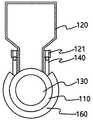
- FIG. 2is a cross-sectional view illustrating a portion A of FIG. 1 .
- FIG. 3is a view showing in detail the structure of the screw according to the present invention.
- (a)is a cross-linked polyethylene screw, (b) a polymer screw, and (c) a rubber screw.
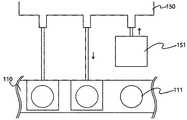
- FIG. 5is a plan view showing the opening and closing means of the present invention.
- FIG. 6is a block diagram illustrating an operation control system of the present invention.
- the variable extrusion molding apparatus 100includes a hopper 120 in which a plurality of openings 111 are formed on the upper portion of the barrel 110 and movable to any one position among the plurality of openings 111 depending on the material, and the material from the hopper
- a plurality of screws 130prepared to receive and advance pressurized toward the die, and to have different ratios of diameters and effective lengths of each section according to materials, are included.
- FIG. 1is a cross-sectional view illustrating a variable extrusion molding apparatus 100 according to the present invention
- FIG. 2is a cross-sectional view illustrating part A of FIG. 1 .
- the extrusion molding apparatus 100is rotated by inserting a screw 130 into the barrel 110 and receiving the driving force of the driving means 170 .
- the barrel 110has a cylindrical shape, and a plurality of opening and closing openings 111 are formed on one side of the upper portion so that a material can be introduced, and the hopper 120 connected to the opening and closing opening 111 is the inside of the barrel 110 . supply the material with The screw 130 receives the material from the hopper 120 and discharges the material toward the die.
- the opening/closing opening 111can use multiple sections at the same time, and materials can be directly fed without the hopper 120 .
- the effective length of the screw 130is the same as the position of the opening 111, and the ratio of the diameter and the effective length of each section is different depending on the material.
- FIG 3is a view showing the structure of the screw 130 in detail.
- the hopper 120is varied according to the material, and the screw 130 of the required length is selected and mounted on the extrusion molding apparatus.
- the screw 130forms a supply part, a compression part, and a metering part.
- the supply partreceives the material from the hopper 120 and is transferred, and the depth of the thread is deep
- the compression partis a section where the material received from the supply part is melted and compressed while the valley depth is gradually lowered.
- the metering sectionis a section in which the melted and kneaded raw material is transported, and is formed to have the lowest depth of the valley.
- (a)is a cross-linked polyethylene screw
- (b)is a polymer screw
- (c)is a rubber screw.
- the control unit 180may control the conveying unit 140 , the driving unit 170 , and the heating unit 160 .
- the transfer means 140transfers the hopper 120 to the corresponding opening 111 according to the material.
- the method of transporting the hopper 120is to raise the hopper 120 equipped with the roller 121 to the rail rod-shaped transfer means 140 fixed to the upper portion of the barrel 110 and move it in the transverse direction along the rail rod. .
- the heating means 160is divided into predetermined zones in a form surrounding the outer peripheral surface of the barrel 110, and only a necessary zone is selectively heated as much as the effective length of the inserted screw 130, thereby reducing power wastage.
- FIG. 6is a plan view showing the opening and closing means of the present invention, the plurality of openings and closing openings are opened and closed by the opening and closing means.
- the opening/closing means 150is installed above the opening/closing opening 111 to close the area in which the hopper 120 moved according to the control of the control unit 180 is not located.
- the present inventioncan be used for variable extrusion equipment that can control the position of the hopper of the extruder and can mold various materials by providing a screw suitable for the material.
Landscapes
- Engineering & Computer Science (AREA)
- Mechanical Engineering (AREA)
- Physics & Mathematics (AREA)
- Thermal Sciences (AREA)
- Extrusion Moulding Of Plastics Or The Like (AREA)
Abstract
Description
Translated fromKorean본 발명은 가변 압출 성형장치에 관한 것으로, 상세하게는 압출기 호퍼의 위치를 조절하고 그에 따른 스크루를 선택 장착하여 하나의 압출기에서 다양한 재료를 압출 성형할 수 있는 가변 압출 성형장치에 관한 것이다.The present invention relates to a variable extrusion molding apparatus, and more particularly, to a variable extrusion molding apparatus capable of extruding various materials in one extruder by adjusting the position of the extruder hopper and selectively mounting screws accordingly.
압출기는 호퍼를 통해 공급된 원료에 열과 압력을 가하여 용융시킨 후 스크루의 회전에 의해 금형(die)을 통과시킴으로써 봉, 파이프 또는 시트형상 등의 제품을 성형하는 장치이다.The extruder is a device that forms products such as rods, pipes, or sheets by applying heat and pressure to the raw material supplied through the hopper, melting it, and then passing the die through the rotation of the screw.
압출기는 일반적으로 재료에 따라 스크루의 직경과 유효길이의 비율이 달라져야 하므로 재료별로 다른 압출기가 필요하여 설비 비용과 설치 면적이 늘어나는 문제점이 있다.In general, the extruder needs to have a different ratio of screw diameter and effective length depending on the material, so there is a problem in that a different extruder is required for each material, thereby increasing equipment cost and installation area.
종래의 기술은 다수의 공급 포트를 갖춘 용융 혼련 장치를 사용하여 조성물을 제조하기 위한 방법에 관하여 개시되어 있지만, 기다란 원통형 배럴을 구간마다 연결하여 장시간에 걸쳐 안정적으로 작동하는 것에 문제점이 있다.Although the prior art has been disclosed with respect to a method for preparing a composition using a melt-kneading apparatus equipped with a plurality of supply ports, there is a problem in stably operating over a long period of time by connecting an elongated cylindrical barrel at each section.
상기와 같은 문제점을 해결하기 위하여 본 발명은 각각의 재료에 대응하여 호퍼의 위치를 가변하여 하나의 압출기로 복수의 재료를 성형할 수 있는 가변 압출 성형장치를 제공한다.In order to solve the above problems, the present invention provides a variable extrusion molding apparatus capable of molding a plurality of materials with one extruder by varying the position of the hopper in response to each material.
본 발명은 재료에 따라 다른 길이의 스크루를 구비하여 하나의 압출 성형장치로 다양한 재료를 수용할 수 있는 가변 압출 성형장치를 제공한다.The present invention provides a variable extrusion molding apparatus capable of accommodating various materials with one extrusion molding apparatus by having screws of different lengths depending on the material.
본 발명에 따른 가변 압출 성형장치는, 배럴(110) 상부에 복수의 개폐구(111)가 형성되어 재료에 따라 상기 복수의 개폐구 중 어느 하나의 위치로 이동 가능한 호퍼(120) 및 상기 호퍼로부터 재료를 전달받아 다이 쪽으로 가압 전진시키고, 재료에 따라 각 구간의 직경과 유효길이의 비율이 다르게 준비된 복수의 스크루(130)를 포함하여 재료에 따라 호퍼를 가변시키고 그에 따른 길이의 스크루를 선택하여 압출 성형장치에 장착하는 것을 특징으로 한다.The variable extrusion molding apparatus according to the present invention includes a
상기 호퍼는 이송수단(140)에 의하여 위치가 가변되고 그에 따른 스크루를 선택 사용하는 것을 특징으로 한다.The hopper is characterized in that the position is changed by the transfer means 140, and the screw is selected and used accordingly.
상기 복수의 개폐구는 개폐수단에 의하여 개폐되는 것을 특징으로 한다.The plurality of opening and closing openings are characterized in that the opening and closing means.
상기 이송수단은 레일봉 형태로 상기 호퍼의 하단부에 결합된 롤러와 상기 롤러와 결합되어 횡방향으로 슬라이드되도록 형성된 것을 특징으로 한다.The conveying means is coupled to the roller coupled to the lower end of the hopper in the form of a rail rod and is characterized in that it is formed to slide in the transverse direction.
상기 배럴 외주면은 가열수단이 소정 구역으로 나뉘어져 있어 재료에 따라 선택적으로 가열되는 것을 특징으로 한다.The outer circumferential surface of the barrel is characterized in that the heating means is divided into predetermined regions and selectively heated according to the material.
본 발명은 압출기의 호퍼 위치를 조절하고, 재료에 따른 스크루를 구비하여 다양한 재료를 성형할 수 있기 때문에 설비 투자 대수 감소와 설치 면적을 줄일 수 있어 투자비용을 절감할 수 있다.The present invention can reduce the investment cost by controlling the position of the hopper of the extruder, and by providing a screw according to the material to form various materials, thereby reducing the number of equipment investment and reducing the installation area.
또한, 하나의 압출 장비를 사용하므로 가동률을 높여 생산 단가를 낮출 수 있다.In addition, since a single extrusion equipment is used, the production cost can be lowered by increasing the utilization rate.
도 1은 본 발명에 따른 가변 압출 성형장치를 도시한 단면도이다.1 is a cross-sectional view showing a variable extrusion molding apparatus according to the present invention.
도 2는 도 1의 A 부분을 도시한 단면도이다.FIG. 2 is a cross-sectional view illustrating a portion A of FIG. 1 .
도 3은 본 발명에 따른 스크루의 구조를 상세하게 나타낸 도면이다.3 is a view showing in detail the structure of the screw according to the present invention.
도 4는 재료에 따른 유효길이를 다르게 형성한 실시예로 (a)는 가교폴리에틸렌용, (b)는 폴리머용 스크루, (c)는 고무용 스크루를 도시한 도면이다.4 is an embodiment in which the effective length is formed differently according to the material. (a) is a cross-linked polyethylene screw, (b) a polymer screw, and (c) a rubber screw.
도 5는 본 발명의 개폐수단을 도시한 평면도이다.5 is a plan view showing the opening and closing means of the present invention.
도 6은 본 발명의 동작 제어 시스템을 도시한 블록도이다.6 is a block diagram illustrating an operation control system of the present invention.
가변 압출 성형장치(100)는 배럴(110) 상부에 복수의 개폐구(111)가 형성되어 재료에 따라 상기 복수의 개폐구(111) 중 어느 하나의 위치로 이동 가능한 호퍼(120)와 상기 호퍼로부터 재료를 전달받아 다이(die) 쪽으로 가압 전진시키고, 재료에 따라 각 구간의 직경과 유효길이의 비율이 다르게 준비된 복수의 스크루(130)를 포함한다.The variable
도 1은 본 발명에 따른 가변 압출 성형장치(100)를 도시한 단면도이며, 도 2는 도 1의 A 부분을 도시한 단면도이다.FIG. 1 is a cross-sectional view illustrating a variable
상기 압출 성형장치(100)는 배럴(110) 내부에 스크루(130)가 삽입되고 구동수단(170)의 구동력을 전달받아 회전한다. 상기 배럴(110)은 원통 형상을 하며, 일측 상부에는 재료가 투입될 수 있도록 복수의 개폐구(111)가 형성되고, 여기에서 상기 개폐구(111)와 연결되는 호퍼(120)는 배럴(110) 내부로 재료를 공급한다. 상기 스크루(130)는 호퍼(120)로부터 재료를 전달받아 다이 쪽으로 재료가 배출된다.The
상기 개폐구(111)는 다구간을 동시에 사용할 수 있으며 호퍼(120)없이 직접 재료가 투입될 수 있다.The opening/
상기 스크루(130)의 유효길이는 개폐구(111)의 위치와 동일하며, 재료에 따라 각 구간의 직경(diameter)과 유효길이(length)의 비율을 다르게 형성한다.The effective length of the
도 3은 스크루(130)의 구조를 상세하게 나타낸 도면이다. 재료에 따라 호퍼(120)를 가변시키고 필요한 길이의 스크루(130)를 선택하여 압출 성형장치에 장착한다.3 is a view showing the structure of the
상기 스크루(130)는 공급부, 압축부, 계량부를 형성한다. 상기 공급부는 호퍼(120)로부터 재료를 전달받아 이송되는 부분으로 나사산의 깊이가 깊고, 압축부는 공급부에서 전달받은 재료가 녹으면서 압축되는 구간으로 골 깊이가 점차 낮아진다. 계량부는 녹아서 혼련된 원료가 이송되는 구간으로 골 깊이가 가장 낮도록 형성된다.The
도 4는 재료에 따른 유효길이를 다르게 형성한 실시예로 (a)는 가교폴리에틸렌용 스크루, (b)는 폴리머용 스크루를 (c)는 고무용 스크루를 도시한 도면이다.4 is an embodiment in which the effective length is formed differently according to the material. (a) is a cross-linked polyethylene screw, (b) is a polymer screw, and (c) is a rubber screw.
도 5는 본 발명의 동작 제어 시스템을 도시한 블록도이다. 제어수단(180)은 이송수단(140)과 구동수단(170) 및 가열수단(160)을 제어할 수 있다.5 is a block diagram illustrating an operation control system of the present invention. The
상기 이송수단(140)은 재료에 따라 해당 개폐구(111)로 상기 호퍼(120)를 이송한다. 호퍼(120)를 이송하는 방법은 배럴(110) 상부에 고정된 레일봉 형태의 이송수단(140)에 롤러(121)를 장착한 호퍼(120)를 올리고 레일봉을 따라 횡방향으로 이동되도록 한다.The transfer means 140 transfers the
상기 가열수단(160)은 배럴(110)의 외주면을 둘러싼 형태로 소정 구역으로 나뉘어져 있으며, 삽입된 스크루(130)의 유효길이만큼 필요한 구역만 선택적으로 가열되어 전력 낭비를 줄일 수 있다.The heating means 160 is divided into predetermined zones in a form surrounding the outer peripheral surface of the
도 6은 본 발명의 개폐수단을 도시한 평면도로, 상기 복수의 개폐구는 개폐수단에 의하여 개폐된다.6 is a plan view showing the opening and closing means of the present invention, the plurality of openings and closing openings are opened and closed by the opening and closing means.
상기 개폐수단(150)은 개폐구(111) 상부로 설치되어 제어수단(180)의 제어에 따라 이동된 호퍼(120)가 위치하지 않는 영역은 폐쇄한다.The opening/
본 발명은 압출기의 호퍼 위치를 조절하고, 재료에 적합한 스크루를 구비하여 다양한 재료를 성형할 수 있는 가변 압출 장비에 사용할 수 있다.The present invention can be used for variable extrusion equipment that can control the position of the hopper of the extruder and can mold various materials by providing a screw suitable for the material.
Claims (5)
Translated fromKoreanApplications Claiming Priority (2)
| Application Number | Priority Date | Filing Date | Title |
|---|---|---|---|
| KR1020190175037AKR102112988B1 (en) | 2019-12-26 | 2019-12-26 | Changeable extruder |
| KR10-2019-0175037 | 2019-12-26 |
Publications (1)
| Publication Number | Publication Date |
|---|---|
| WO2021132820A1true WO2021132820A1 (en) | 2021-07-01 |
Family
ID=70919804
Family Applications (1)
| Application Number | Title | Priority Date | Filing Date |
|---|---|---|---|
| PCT/KR2020/007821CeasedWO2021132820A1 (en) | 2019-12-26 | 2020-06-17 | Variable extrusion molding device |
Country Status (2)
| Country | Link |
|---|---|
| KR (1) | KR102112988B1 (en) |
| WO (1) | WO2021132820A1 (en) |
Families Citing this family (1)
| Publication number | Priority date | Publication date | Assignee | Title |
|---|---|---|---|---|
| KR102112988B1 (en)* | 2019-12-26 | 2020-05-20 | 김도상 | Changeable extruder |
Citations (6)
| Publication number | Priority date | Publication date | Assignee | Title |
|---|---|---|---|---|
| JPH03211027A (en)* | 1990-01-17 | 1991-09-13 | Hitachi Chem Co Ltd | Injection molding machine |
| KR930001616Y1 (en)* | 1990-10-11 | 1993-04-08 | 김기호 | Extruding machine |
| JP2010158644A (en)* | 2009-01-09 | 2010-07-22 | Yanmar Co Ltd | Sorter |
| KR20120093659A (en)* | 2011-02-15 | 2012-08-23 | (주)삼박 | Forming system and method of fiber reinforced thermoplastic composite material |
| KR20130084598A (en)* | 2010-05-28 | 2013-07-25 | 코헤이 사와 | Kneading extrusion device |
| KR102112988B1 (en)* | 2019-12-26 | 2020-05-20 | 김도상 | Changeable extruder |
Family Cites Families (2)
| Publication number | Priority date | Publication date | Assignee | Title |
|---|---|---|---|---|
| JPS59230734A (en)* | 1983-06-14 | 1984-12-25 | Mitsui Toatsu Chem Inc | Screw type extrusion molding equipment for thermosetting resin |
| JP4224894B2 (en) | 1999-06-04 | 2009-02-18 | チッソ株式会社 | Method for producing composite reinforced polyolefin resin composition and apparatus for producing the same |
- 2019
- 2019-12-26KRKR1020190175037Apatent/KR102112988B1/enactiveActive
- 2020
- 2020-06-17WOPCT/KR2020/007821patent/WO2021132820A1/ennot_activeCeased
Patent Citations (6)
| Publication number | Priority date | Publication date | Assignee | Title |
|---|---|---|---|---|
| JPH03211027A (en)* | 1990-01-17 | 1991-09-13 | Hitachi Chem Co Ltd | Injection molding machine |
| KR930001616Y1 (en)* | 1990-10-11 | 1993-04-08 | 김기호 | Extruding machine |
| JP2010158644A (en)* | 2009-01-09 | 2010-07-22 | Yanmar Co Ltd | Sorter |
| KR20130084598A (en)* | 2010-05-28 | 2013-07-25 | 코헤이 사와 | Kneading extrusion device |
| KR20120093659A (en)* | 2011-02-15 | 2012-08-23 | (주)삼박 | Forming system and method of fiber reinforced thermoplastic composite material |
| KR102112988B1 (en)* | 2019-12-26 | 2020-05-20 | 김도상 | Changeable extruder |
Also Published As
| Publication number | Publication date |
|---|---|
| KR102112988B1 (en) | 2020-05-20 |
Similar Documents
| Publication | Publication Date | Title |
|---|---|---|
| US4906171A (en) | Directed flow die assembly | |
| EP2428347B1 (en) | Device and method for producing oval plastic containers | |
| EP3022040B1 (en) | Device for producing films stretched in-line | |
| US10427347B2 (en) | Ram extruding thin panels of UHMW polymers | |
| WO2021132820A1 (en) | Variable extrusion molding device | |
| CN104441541A (en) | Wood-plastic composite material production unit | |
| EP2173533A2 (en) | Method for producing blow-moulded hollow bodies | |
| EP0885108A1 (en) | Electromechanical drive assembly for an accumulator head | |
| CN203198226U (en) | Pipe extrusion die | |
| CN207224417U (en) | A kind of extrusion device with adjustable pre-coating film longitudinal uniformity | |
| JPH06509033A (en) | Accumulator head for extrusion blow molding machine | |
| CN110154352A (en) | A kind of PVC pipe production technology | |
| US11292172B2 (en) | Ram extruding thin panels of UHMW polymers | |
| CN103935001A (en) | Plastic extruder | |
| KR101134945B1 (en) | A extrusion die unit | |
| SK6552002A3 (en) | Extruder for preparation of rubber mixtures | |
| CN104057597B (en) | Self-circulating oil heating reaction type extruder, and working method and application thereof | |
| US3212132A (en) | Apparatus for extrusion molding of thermoplastic rods | |
| US3245116A (en) | Plastic molding machine | |
| CN102039657B (en) | Extrusion moulding apparatus for large-scale macromolecular product and process thereof | |
| CN205343733U (en) | Braided bag production of material system | |
| KR20220132822A (en) | Continuous Extrusion Molding Apparatus capable of speed control | |
| KR20130008269A (en) | Drying apparatus for ceramic extrusion molded body | |
| CN103817161B (en) | A kind of manufacture warm cold-extruded forging pipe drawing device | |
| CN119502302B (en) | Adjustable extrusion type plastic hose forming machine for cables |
Legal Events
| Date | Code | Title | Description |
|---|---|---|---|
| 121 | Ep: the epo has been informed by wipo that ep was designated in this application | Ref document number:20904581 Country of ref document:EP Kind code of ref document:A1 | |
| NENP | Non-entry into the national phase | Ref country code:DE | |
| 122 | Ep: pct application non-entry in european phase | Ref document number:20904581 Country of ref document:EP Kind code of ref document:A1 |