WO2021131670A1 - Work machine - Google Patents
Work machineDownload PDFInfo
- Publication number
- WO2021131670A1 WO2021131670A1PCT/JP2020/045664JP2020045664WWO2021131670A1WO 2021131670 A1WO2021131670 A1WO 2021131670A1JP 2020045664 WJP2020045664 WJP 2020045664WWO 2021131670 A1WO2021131670 A1WO 2021131670A1
- Authority
- WO
- WIPO (PCT)
- Prior art keywords
- roof
- work
- support frame
- height
- machine according
- Prior art date
- Legal status (The legal status is an assumption and is not a legal conclusion. Google has not performed a legal analysis and makes no representation as to the accuracy of the status listed.)
- Ceased
Links
Images


Classifications
- A—HUMAN NECESSITIES
- A01—AGRICULTURE; FORESTRY; ANIMAL HUSBANDRY; HUNTING; TRAPPING; FISHING
- A01B—SOIL WORKING IN AGRICULTURE OR FORESTRY; PARTS, DETAILS, OR ACCESSORIES OF AGRICULTURAL MACHINES OR IMPLEMENTS, IN GENERAL
- A01B69/00—Steering of agricultural machines or implements; Guiding agricultural machines or implements on a desired track
- A—HUMAN NECESSITIES
- A01—AGRICULTURE; FORESTRY; ANIMAL HUSBANDRY; HUNTING; TRAPPING; FISHING
- A01C—PLANTING; SOWING; FERTILISING
- A01C11/00—Transplanting machines
- A01C11/02—Transplanting machines for seedlings
- B—PERFORMING OPERATIONS; TRANSPORTING
- B62—LAND VEHICLES FOR TRAVELLING OTHERWISE THAN ON RAILS
- B62D—MOTOR VEHICLES; TRAILERS
- B62D25/00—Superstructure or monocoque structure sub-units; Parts or details thereof not otherwise provided for
- B62D25/06—Fixed roofs
- G—PHYSICS
- G05—CONTROLLING; REGULATING
- G05D—SYSTEMS FOR CONTROLLING OR REGULATING NON-ELECTRIC VARIABLES
- G05D1/00—Control of position, course, altitude or attitude of land, water, air or space vehicles, e.g. using automatic pilots
- G05D1/20—Control system inputs
- G05D1/24—Arrangements for determining position or orientation
- G05D1/246—Arrangements for determining position or orientation using environment maps, e.g. simultaneous localisation and mapping [SLAM]
- G—PHYSICS
- G05—CONTROLLING; REGULATING
- G05D—SYSTEMS FOR CONTROLLING OR REGULATING NON-ELECTRIC VARIABLES
- G05D1/00—Control of position, course, altitude or attitude of land, water, air or space vehicles, e.g. using automatic pilots
- G05D1/20—Control system inputs
- G05D1/24—Arrangements for determining position or orientation
- G05D1/247—Arrangements for determining position or orientation using signals provided by artificial sources external to the vehicle, e.g. navigation beacons
- G05D1/248—Arrangements for determining position or orientation using signals provided by artificial sources external to the vehicle, e.g. navigation beacons generated by satellites, e.g. GPS
- B—PERFORMING OPERATIONS; TRANSPORTING
- B60—VEHICLES IN GENERAL
- B60Y—INDEXING SCHEME RELATING TO ASPECTS CROSS-CUTTING VEHICLE TECHNOLOGY
- B60Y2200/00—Type of vehicle
- B60Y2200/20—Off-Road Vehicles
- B60Y2200/22—Agricultural vehicles
- G—PHYSICS
- G05—CONTROLLING; REGULATING
- G05D—SYSTEMS FOR CONTROLLING OR REGULATING NON-ELECTRIC VARIABLES
- G05D2105/00—Specific applications of the controlled vehicles
- G05D2105/15—Specific applications of the controlled vehicles for harvesting, sowing or mowing in agriculture or forestry
- G—PHYSICS
- G05—CONTROLLING; REGULATING
- G05D—SYSTEMS FOR CONTROLLING OR REGULATING NON-ELECTRIC VARIABLES
- G05D2107/00—Specific environments of the controlled vehicles
- G05D2107/20—Land use
- G05D2107/21—Farming, e.g. fields, pastures or barns
Definitions
- the present inventionrelates to a working machine such as a riding type rice transplanter and a riding type direct seeding machine.
- some work machinesthat work and run in a field that is a work site perform work while automatically running on a preset running route.
- Such a work machinetravels on a preset travel route of a work site while specifying the position of the vehicle while traveling by a satellite signal.
- the work machinemay collide with ridges or perform unnecessary work on the adjacent work place. Therefore, it is required to more accurately detect whether or not the work machine exists in the work site.
- the second object of the present inventionis to accurately detect whether or not the working machine exists in the working area.
- the opening of the rooffaces in the direction along the upper surface of the roof, not upward.
- the roofis supported by the support frame and the opening faces forward so that the front portion of the roof is in a forward leaning posture lower than the rear portion of the roof in a side view. Is suitable.
- the roofwhen a strong wind blows from the front side toward the aircraft, the roof is in a forward leaning posture so that the roof is pressed downward, and a part of the strong wind. It is advantageous in terms of preventing damage to the roof, because it is possible to obtain a state in which the roof escapes from the opening of the roof through a continuous passage to the lower side of the roof.
- the roofwhen a strong wind blows from the rear side toward the aircraft, the roof is in a forward leaning posture, so that the strong wind blows into the lower side of the roof.
- the state in which the roof is liftedis weakened, which is advantageous in terms of preventing damage to the roof. ..
- the opening of the rooffaces the front direction, which is the direction along the upper surface of the roof, when a strong wind blows from the rear side toward the aircraft as described above, a part of the strong wind is on the roof. Since it can be smoothly pulled out from the opening in the forward direction, it is advantageous in terms of preventing damage to the roof.
- a plurality of divided roof portionsare provided on the roof so as to be arranged side by side along the front-rear direction, and in the roof portions adjacent in the front-rear direction, the rear portion of the front roof portion. Is arranged so that the rear portion of the front roof portion and the front portion of the rear roof portion are overlapped with each other so as to be located below the front portion of the rear roof portion.
- a portionis provided in which the rear portion of the front roof portion and the front portion of the rear roof portion are separated from each other in the vertical direction. It is preferable that the connecting passage is provided.
- a plurality of divided roof portionsare provided, and one roof portion is relatively small, so that the roof portion is easy to handle and easy to produce. It becomes a thing.
- Thisis advantageous in terms of improving productivity as compared with a configuration in which a large roof that is not divided into a plurality of roof portions is handled.
- a cushioning materialis provided between the rear portion of the front roof portion and the front portion of the rear roof portion.
- a first support frame that supports one of the front and rear parts of the roof and a second support frame that supports the other of the front and rear parts of the roofare provided, and the navigation satellite is provided with a second support frame.
- a positioning unit that outputs positioning data indicating the position of the aircraft based on the positioning signalis supported by the first support frame so as to be located at the same height as one of the front part and the rear part of the roof in a side view. It is preferable that the roof is used.
- the positioning unitis supported by the first support frame, so that the first support frame can be used. It is used for both roof support and positioning unit support, which is advantageous in terms of structural simplification.
- a recess into which the positioning unit can enteris provided in one of the front portion and the rear portion of the roof in a plan view.
- the left-right width of the recessis set to be larger than the left-right width of the positioning unit.
- the work equipmentmay be equipped with another device for communication or the like.
- the left-right width of the recess of the roofis set to be larger than the left-right width of the positioning unit, so that another device in addition to the positioning unit is placed in the support frame so as to enter the recess of the roof. It can be easily supported.
- the first and second support framesare set to the first work height and the second work height, the roof is set to the work position, and the roof is set to the first by the connecting mechanism. It is connected to the support frame of 1.
- the height of the second support frameis changed from the second working height to the second non-working height lower than the second working height by the second height changing mechanism, and the second supporting frame is changed.
- the roof supported by the roofis also set at a low position together with the second support frame. At this time, by setting the roof to a non-working position by the support mechanism, the roof is separated from the first support frame.
- a right front-rear drainage channel having a concave cross sectionis provided along the front-rear direction on the right portion of the upper surface of the roof
- a left front-rear drainage channel having a concave cross sectionis provided on the left portion of the upper surface of the roof in the front-rear direction.
- a plurality of left and right drainage channels having a concave cross sectionare provided along the left and right directions on the upper surface of the roof and are connected to the front and rear drainage channels, and rainwater is drained from the front and rear drainage channels on the right and left sides. It is preferable to be done.
- front and rear drainage channels and left and right drainage channelsare provided on the upper surface of the roof, and rainwater is mainly drained from the front and rear drainage channels.
- the front and rear drainage channels having a concave cross section and the left and right drainage channels having a concave cross sectionare arranged on the upper surface of the roof so as to intersect each other, the front and rear drainage channels and the left and right drainage channels function as reinforcing portions of the roof. , The rigidity of the roof can be improved.
- the working deviceis supported by the rear part of the machine body and rainwater is drained from the front part of the front and rear drainage channels on the right and left sides.
- the work machineis a work machine that runs on the work site according to the work instruction value, and is a satellite that receives a satellite signal from the satellite.
- the work instruction valueis input to each of an antenna, a satellite positioning module that outputs positioning data corresponding to the position of the own vehicle based on the satellite signal, and a mesh-shaped section associated with the work site.
- Own vehicle position determinationfor determining whether or not the own vehicle position is within the work site according to the storage unit for storing the work plan map and the work instruction value input to the section corresponding to the own vehicle position. It has a part.
- the work machine that identifies the position of the own vehicle based on the satellite signal from the satelliteruns while checking the position of the own vehicle in the work area by associating the work area map and the position of the own vehicle with the position of the own vehicle. Even in such a work machine, the work machine may deviate from the work place due to a malfunction of the work place map, a malfunction of a positioning unit such as a satellite antenna, a detection error of the position of the own vehicle, or the like.
- the work instruction valueincludes a non-work value for not performing the work
- the own vehicle position determination unitindicates that the own vehicle position is outside the work area when the work instruction value is the non-work value. It may be determined that there is.
- the work instruction value for determining that the vehicle position is outside the work areais clarified, and it is possible to more easily determine whether or not the vehicle position is inside the work area. It is possible to accurately confirm whether or not the position is within the work area.
- a map correction unit for modifying the work plan mapis provided, and the work instruction value for performing the work is a work value in a predetermined range larger than the non-work value.
- the work area map showncan be referred to, and the map correction unit may correct the work value of the section corresponding to the outer peripheral position to a value between the non-work value and the work value.
- a notification unitthat notifies a warning when the vehicle position is determined to be outside the work site by the vehicle position determination unit.
- the driver and the workercan recognize that the position of the own vehicle is outside the work area, and can be an opportunity to take an appropriate response.
- a notification unitmay be provided to notify a warning when the vehicle position is determined by the vehicle position determination unit to be outside the work area and the vehicle is in a working state.
- the workmay be performed with the reference work value.
- the standard work value for such a specific workis set in advance, and when the work deviates from the work site and the work is carried out, the work can be automatically performed at the standard work value, which is efficient. It is possible to carry out work running.
- the work related to the work runningis a fertilizer application work
- the work instruction valuemay be the amount of fertilizer to be fertilized.
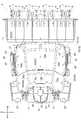
- the spare seedling support frame and support frame at the front of the machinewere set to the first non-working height, the support frame at the rear of the machine was set to the second non-working height, and the roof was set to the non-working position. It is a left side view of the state.
- FIGS. 1 to 13show a passenger-type rice transplanter, which is an example of a working machine.
- Findicates a forward direction
- Bindicates a backward direction
- Uindicates an upward direction
- Dindicates a downward direction
- Rindicates a right direction
- Lindicates a left direction. ..
- the passenger-type rice transplantermoves the link mechanism 3 and the link mechanism 3 up and down to the rear part of the machine body 11 provided with the right and left front wheels 1 and the right and left rear wheels 2.
- a hydraulic cylinder 4is provided, a seedling planting device 5 (corresponding to a working device) is supported at the rear of the link mechanism 3, and the seedling planting device 5 is supported at the rear of the machine body 11.
- a planting arm 8, a float 9, a seedling stand 10 and the like supported at both endsare provided.
- a fertilizer application device 12(corresponding to a work device) is supported over the rear part of the machine body 11 and the seedling planting device 5, and the fertilizer application device 12 includes a hopper 13, a feeding portion 14, a blower 15, a groove making device 16, and a hose. 17 etc. are provided.
- the driver's seat 18is supported at the rear of the aircraft 11.
- a hopper 13 for storing fertilizer and a feeding portion 14are provided in a portion on the rear side of the driver's seat 18 in the machine body 11, and a blower 15 is provided on the lateral outer side on the left side of the feeding portion 14. .
- a grooving device 16is attached to the float 9, and a hose 17 is connected to the feeding portion 14 and the grooving device 16.
- the planting arm 8(rotary case 7) is rotationally driven while the seedling stand 10 is reciprocally driven laterally, and the planting arm 8 transfers seedlings from the lower part of the seedling stand 10. Take it out and plant it on the rice field.
- the fertilizer of the hopper 13is fed out by the feeding portion 14, and is supplied to the groove making device 16 through the hose 17 by the transport wind of the blower 15. While doing so, fertilizer is supplied from the groove making device 16 to the groove on the rice field.
- FIGS. 1, 2 and 3Structure of the front part of the aircraft
- an engine(not shown) is supported at the front portion of the airframe 11, a bonnet 19 covering the engine is provided, and a steering handle 20 for steering and operating the front wheel 1 is provided. It is provided at the rear of the bonnet 19.
- Right and left steps 21 for getting on and offare provided on the right and left sides of the bonnet 19.
- the right and left spare seedling cradle frames 22(corresponding to the first support frame) are connected to the lower part of the front part of the machine body 11 and extend laterally outward, and the lateral outer side of the right and left step 21 is upward. It has been extended to.
- the spare seedling stand frame 22is formed in an arch shape (bifurcated shape) in a side view, and three spare seedling stand frames 23 are supported by the spare seedling stand frame 22.
- the central reserve seedling pedestal 23is supported by the preliminary seedling pedestal frame 22, and the front sapling pedestal 23 is located at the front of the central preliminary seedling pedestal 23. It is supported so as to be swingable in the front-rear direction, and the rear spare seedling stand 23 is supported so as to be swingable in the front-rear direction at the rear portion of the central spare seedling stand 23.
- the front spare seedling stand 23is operated to the rear side and the rear spare seedling stand 23 is operated to the front side with respect to the center spare seedling stand 23.
- the front and rear spare seedling pedestals 23are stacked on the upper part of the central spare seedling pedestal 23.
- the front spare seedling pedestal 23is operated to the front side and the rear spare seedling pedestal 23 is operated to the rear side with respect to the central reserve seedling pedestal 23.
- the three spare seedling pedestals 23can be set in a state of being unfolded in a row.
- an arch-shaped support frame 24(corresponding to the first support frame) is provided in a front view.
- the support frame 24is formed by bending a round pipe, and is provided with a horizontal portion 24a along the left-right direction, a right and left vertical portion 24b, and a right and left front-rear facing portion 24c.
- a channel-shaped bracket 22ais connected to the upper part of the right and left spare seedling stand frames 22, and the end portion of the front-rear facing portion 24c of the support frame 24 swings around the axis P1 along the left-right direction. It is possible to be supported by the bracket 22a of the spare seedling stand frame 22.
- the support frame 24(vertical portion 24b) faces upward with respect to the bracket 22a of the spare seedling stand frame 22, and the spare seedling stand frame 22 And the support frame 24 is in a state of being set to the first working height H11.
- the support frame 24can be fixed at the first working height H11 by attaching a fixing member (not shown) over the bracket 22a of the spare seedling rest frame 22 and the front-rear facing portion 24c of the support frame 24. it can.
- the vertical portion 24b of the support frame 24is turned downward and is spared.
- the seedling rest frame 22 and the support frame 24can be set to the first non-working height H12, which is lower than the first working height H11.
- the support frame 24can be fixed at the first non-working height H12 by attaching the removed fixing member over the bracket 22a of the spare seedling base frame 22 and the front-rear facing portion 24c of the support frame 24.
- the first height changing mechanism 31is provided so that the height of the spare seedling rest frame 22 and the support frame 24 can be changed over the first working height H11 and the first non-working height H12. There is.
- the first height changing mechanism 31is provided with a bracket 22a of the spare seedling stand frame 22, a front-rear facing portion 24c of the support frame 24, a fixing member, and the like.
- the positioning unit 25is attached to the left-right center portion of the lateral portion 24a of the support frame 24. As described above (configuration of the first support frame at the front part of the machine body), the reserve seedling stand frame 22 and the support frame 24 extend over the first working height H11 and the first non-working height H12. When the height is changed, the positioning unit 25 moves integrally with the support frame 24.
- the positioning unit 25is provided with a receiving device (not shown) for acquiring position information by a satellite positioning system and an inertial measurement unit (not shown) for detecting the inclination (pitch angle, roll angle) of the airframe 11.
- the positioning unit 25outputs positioning data indicating the position of the machine body 11.
- GNSSGlobal Navigation Satellite System
- GPSGlobal Positioning System
- airframe 11a positioning target
- the right and left support frames 26(corresponding to the second support frame) are connected to the lower part of the rear part of the machine body 11 and extend laterally outward, and laterally to the hopper 13. The outside is extended upward.
- the right and left connecting portions 29are connected to the upper part of the support frame 26.
- the right and left support frames 27are connected to the connection portion 29 and extend upward.
- the reinforcing frame 28is connected to the lower portion of the rear portion of the machine body 11 and the support frame 26.
- the connecting portion 29is formed by bending a plate material, is provided with a notch portion 29a and a connecting hole 29b, and is provided with an opening 29c having a diameter larger than that of the connecting hole 29b. Has been done.
- a bracket 30is connected to a portion of the connecting portion 29 facing the opening 29c, and a round pipe-shaped guide member 33 is connected to the bracket 30.
- a fixing member 34 in which the round bar member is bent in a channel shapeis provided, and the fixing member 34 can swing around the shaft core P2 along the front-rear direction of the guide member 33 and slide along the shaft core P2. It is supported by the guide member 33.
- the spring 35is attached to the spring receiving portion 34b fixed to the fixing member 34 and the bracket 30 while being passed through the opening 29c of the connecting portion 29.
- the fixing member 34is urged by the spring 35 on the side where the end portion 34a of the fixing member 34 enters the connection hole 29b of the connecting portion 29.
- connection pin 27a and a connection hole 27bare provided in the lower part of the support frame 27, and a connection pin 27c and a connection hole 27d are provided in the upper and lower middle portions of the support frame 27.
- the states shown in FIGS. 1, 3, 5, 6 and 11are states in which the support frames 26 and 27 are set to the second working height H21.
- the connection pin 27a of the support frame 27is inserted into the notch 29a of the connection portion 29 from above, the support frame 27 is inserted inside the connection portion 29, and the end portion 34a of the fixing member 34 is the support frame 27 and the connection portion.
- the support frame 27is connected to the connection portion 29 by being inserted over the connection holes 27b, 29b of the 29, and the support frames 26, 27 are set to the second working height H21.
- the states shown in FIGS. 12 and 13are states in which the support frames 26 and 27 are set to the second non-working height H22, which is lower than the second working height H21.
- the connection pin 27c of the support frame 27is inserted into the notch 29a of the connection portion 29 from above, the support frame 27 is inserted inside the connection portion 29, and the end portion 34a of the fixing member 34 is the support frame 27 and the connection portion.
- the support frame 27is connected to the connection portion 29 by being inserted over the connection holes 27d and 29b of the 29, and the support frames 26 and 27 are set to the second non-working height H22.
- the second height changing mechanism 32is provided so that the heights of the support frames 26 and 27 can be changed over the second working height H21 and the second non-working height H22.
- the second height changing mechanism 32is provided with connection pins 27a and 27c of the support frame 27, connection holes 27b and 27d, a connection portion 29, a fixing member 34, a spring 35, and the like.
- a roof 36is provided, and the spare seedling stand frame 22 and the support frame 24, and the support frame 24, so that the roof 36 covers the upper part of the machine body 11 including the driver's seat 18. It is supported by the support frames 26 and 27.
- the roof 36has a frame-shaped portion 37 made of a metal round pipe-shaped member and an elongated plate material, and two roof portions 38, 39 made of synthetic resin. Is provided, and the frame-shaped portion 37 and the roof portions 38 and 39 are connected by bolts.
- brackets 45are upwardly connected to the front portion 40, the horizontal portion 41, the rear portion 42, the intermediate portion 43, and the left and right portions 44.
- the connecting brackets 47 and 48are downwardly connected to the rear portion and the front-rear intermediate portion of the right and left lateral portions 41.
- the connecting bracket 46is forwardly connected to the right and left portions of the front portion 40.
- the portion between the right and left connecting brackets 46 in the front portion 40is bent to the rear side to form a recess 40a opened to the front side.
- the two divided roof portions 38 and 39are provided on the roof 36 so as to be arranged side by side in the front-rear direction.
- the front roof portion 38is integrally composed of synthetic resin.
- a recess 38c opened to the front sideis provided in the front portion of the roof portion 38 (roof 36), and the rear portion 38d of the front roof portion 38 is formed in a flat shape.
- a right front-rear drainage channel 38a having a concave cross sectionis provided along the front-rear direction on the right portion of the upper surface of the front roof portion 38 (roof 36), and a left front-rear drainage channel having a concave cross section is provided.
- a road 38ais provided along the front-rear direction on the left portion of the upper surface of the front roof portion 38 (roof 36).
- Two left and right drainage channels 38b having a concave cross sectionare provided on the upper surface of the front roof portion 38 (roof 36) along the left-right direction and are connected to the front and rear drainage channels 38a on the right and left sides.
- the rear roof portion 39is integrally composed of synthetic resin.
- the right front and rear drainage channels 39a having a concave cross sectionare provided along the front-rear direction on the right side of the upper surface of the rear roof portion 39 (roof 36), and the left front and rear drainage channels 39a having a concave cross section are the rear roof. It is provided on the left side of the upper surface of the portion 39 (roof 36) along the front-rear direction.
- Left and right drainage channels 39b having a concave cross sectionare provided on the upper surface of the rear roof portion 39 (roof 36) along the left-right direction and are connected to the right and left front and rear drainage channels 39a.
- the rear portion 38d of the front roof portion 38 and the rear portion 38d of the front roof portion 38are located below the front portion 39c of the rear roof portion 39.
- the front portion 39c of the rear roof portion 39is in contact with and overlapped with each other. In this state, the right and left front and rear drainage channels 38a of the front roof portion 38 and the right and left front and rear drainage channels 39a of the rear roof portion 39 are connected.
- the portion between the right and left front and rear drainage channels 39a in the front portion 39c of the rear roof portion 39is on the upper side. It is raised, and a portion is provided in which the rear portion 38d of the front roof portion 38 and the front portion 39c of the rear roof portion 39 are separated from each other in the vertical direction.
- front and rear roof portions 38, 39 (roof 36)are provided with front and rear roof portions 38, 39 (roof 36), which are lower than the front and rear roof portions 38, 39 (roof 36).
- Communication passages 50 that communicate the area and the opening 49are provided in the front and rear roof portions 38 and 39 (roof 36).
- front and rear roof portions 38 and 39With the front and rear roof portions 38 and 39 arranged as described above, the front and rear roof portions 38 and 39 are connected to the bracket 45 of the frame-shaped portion 37 with bolts.
- a cushioning material 51such as rubber or a slightly hard sponge is sandwiched between the rear portion 38d of the front roof portion 38 and the portion between the right and left front and rear drainage channels 39a in the front portion 39c of the rear roof portion 39. It is provided so that it can be used.
- the connecting bracket 24dis connected to the right and left portions of the lateral portion 24a of the support frame 24.
- a fixing member(not shown) is attached over the connecting bracket 46 of the roof 36 and the connecting bracket 24d of the support frame 24.
- the connecting bracket 46 of the roof 36 and the connecting bracket 24d of the support frame 24are connected.
- the connecting bracket 46 of the roof 36is removed from the connecting bracket 24d of the support frame 24.
- the connecting mechanism 53capable of connecting and disconnecting the spare seedling rest frame 22 and the support frame 24 and the roof 36 is provided.
- the connecting mechanism 53is provided with a connecting bracket 46 for the roof 36, a connecting bracket 24d for the support frame 24, a fixing member, and the like.
- a support portion 54 formed by bending a plate materialis connected to the upper portion of the support frame 27, and a connecting hole 54a is provided in the support portion 54.
- a fixing member 55 in which the round bar member is bent in a channel shapeis provided, and the fixing member 55 can swing around the shaft core P3 along the left-right direction of the support portion 54, and can slide along the shaft core P3. It is supported by the support portion 54.
- the spring 56is attached over the spring receiving portion 55b fixed to the fixing member 55 and the supporting portion 54, and the fixing member is on the side where the end portion 55a of the fixing member 55 enters the connecting hole 54a of the supporting portion 54. 55 is urged by the spring 56.
- the connecting brackets 47 and 48are provided with connecting holes 47a and 48a along the left-right direction.
- the connecting brackets 47 and 48 of the roof 36With the connecting brackets 47 and 48 of the roof 36 inserted into the support portion 54, the end portion 55a of the fixing member 55 extends over the connecting holes 54a of the supporting portion 54 and the connecting holes 47a and 48a of the connecting brackets 47 and 48.
- the roof 36 (connecting brackets 47, 48)is connected to the support frame 27 (support portion 54).
- the fixing member 55By removing the fixing member 55, the roof 36 (connecting brackets 47 and 48) is removed from the support frame 27 (support portion 54).
- the roof 36is located at the working position A1.
- the connecting bracket 46 of the roof 36 and the connecting bracket 24d of the support frame 24can be connected by the connecting mechanism 53.
- the roof 36is located at the non-working position A2. With the roof 36 located at the non-working position A2, the roof 36 separates from the spare seedling rest frame 22, the support frame 24, and the positioning unit 25 in the front-rear direction.
- the spare seedling resting frame 22 and the support frame 24 and the roof 36can be connected to each other by the connecting mechanism 53 at the working position A1 and the connecting mechanism 53 is released.
- a support mechanism 57 capable of supporting the roof 36 in the support frames 26 and 27is provided over the non-working position A2 separated from the frame 24 and the positioning unit 25 in the front-rear direction.
- the support mechanism 57is provided with a support portion 54, a fixing member 55, a spring 56, connecting brackets 47, 48, and the like.
- FIGS. 1, 2, 3 and 11are the states in which the spare seedling rest frame 22 and the support frame 24 are set to the first working height H11, and the support frames 26 and 27 are the second working height H21. It is in the state set to.
- the front part of the roof 36is supported by the reserve seedling stand frame 22 and the support frame 24 so that the front part of the roof 36 is in a forward leaning posture lower than the rear part of the roof 36 in the side view.
- the rear part of the roof 36is supported by the support frames 26 and 27.
- the front part of the roof 36is supported by the reserve seedling stand frame 22 and the support frame 24 so that the positioning unit 25 is located at the same height as the front part of the roof 36 in the side view.
- the positioning unit 25is inserted into the recess 38c of the roof portion 38 in front of the roof 36 and the recess 40a of the front portion 40 in a plan view, and the recesses 38c and 40a into which the positioning unit 25 can enter in a plan view are the roof 36. It is in a state of being provided at the front part of. In this case, the left-right width of the recess 38c of the roof portion 38 in front of the roof 36 and the recess 40a of the front portion 40 is set to be larger than the left-right width of the positioning unit 25.
- the roof 36overlaps the driver's seat 18, the rear of the bonnet 19 and the steering handle 20, the hopper 13 and the feeding portion 14 of the fertilizer application device 12, and the driver's seat 18, the rear of the bonnet 19 and the steering handle 20 overlap.
- the roof 36covers the upper part of the region of the machine body 11 including the hopper 13 and the feeding portion 14 of the fertilizer application device 12.
- rainwater that has fallen on the upper surface of the roof 36may flow into the front and rear drainage channels 38a and 39a of the roof 36, or may flow from the left and right drainage channels 38b and 39b of the roof 36 into the front and rear drainage channels 38a and 39a. It is mainly collected in the front and rear drainage channels 38a and 39a of 36. Since the roof 36 is in a forward leaning posture, the rainwater collected in the front and rear drainage channels 38a and 39a of the roof 36 flows forward along the front and rear drainage channels 38a and 39a of the roof 36, and the front and rear drainage channels 38a of the roof 36. It is drained from the front part of the roof and falls on the reserve seedling stand 23.
- the height of the roof 36 and the likecan be lowered by performing the operation as described below from the above-mentioned (supported state by the first and second support frames on the roof) and the state shown in FIG. ..
- the connecting mechanism 53is set to the released state, and the connecting bracket 46 of the roof 36 is removed from the connecting bracket 24d of the support frame 24.
- the fixing member 55 of the support mechanism 57is removed, and the connecting bracket 47 of the roof 36 is removed from the support portion 54.
- the roof 36is removed from the spare seedling rest frame 22, the support frame 24, and the support frames 26 and 27.
- the preliminary seedling rest frame 22, the support frame 24, and the positioning unit 25are provided by the first height changing mechanism 31. Is set to the first non-working height H12. As described above (configuration of the second support frame at the rear of the machine body) and FIG. 12, the support frames 26 and 27 are set to the second non-working height H22 by the second height changing mechanism 32. ..
- the connecting bracket 48 of the roof 36is connected to the support portion 54, and the roof 36 is positioned at the non-working position A2.
- the roof 36is separated from the spare seedling rest frame 22, the support frame 24, and the positioning unit 25 to the rear side in the front-rear direction, so that the front part of the roof 36 is separated. It does not interfere with the spare seedling stand frame 22, the support frame 24, or the positioning unit 25.
- a fixing membersuch as a belt or a rod may be attached to the front portion of the roof 36 and the steering handle 20 so that the roof 36 does not swing back and forth.
- Embodiment 1In the front and rear roof portions 38 and 39 of the roof 36, the front roof portion 38 is located above the front portion 39c of the rear roof portion 39 so that the rear portion 38d of the front roof portion 38 is located above the front portion 39c of the rear roof portion 39.
- the rear portion 38d and the front portion 39c of the rear roof portion 39may be arranged in contact with each other and overlapped with each other.
- roof portions 38, 39are provided and configured as shown in FIGS. 8, 9 and 10, or as described above (the first alternative embodiment of the first embodiment). It may be configured.
- a plurality of openings 49 facing forwardwhich is a direction along the upper surface of the roof 36
- a plurality of openings 49 facing backwardwhich is a direction along the upper surface of the roof 36.
- the opening 49 facing in the front direction and the opening 49 facing in the rear directionmay be provided in a mixed manner on the roof 36.
- the rice transplanteris provided with a passenger-type, four-wheel drive type traveling machine (hereinafter, referred to as machine 101).
- the machine body 101includes a parallel quadruple link type link mechanism 111 connected to the rear part of the machine body 101 so as to be able to move up and down, a hydraulic lifting cylinder 111a for swinging the link mechanism 111, and a rear end region of the link mechanism 111.
- a seedling planting device 103that is rotatably connected to the seedling planting device 103, and a fertilizer application device 104 that is erected from the rear end region of the machine body 101 to the seedling planting device 103 are provided.
- the seedling planting device 103 and the fertilizer application device 104are examples of working devices.
- the seedling planting device 103is configured as an 8-row planting type as an example.
- the seedling planting device 103includes a seedling stand 131, a planting mechanism 132 for eight rows, and the like.
- the seedling planting device 103can be changed to a type such as 2-row planting, 4-row planting, 6-row planting, etc. by controlling each row clutch (not shown).
- the seedling pedestal 131is a pedestal on which eight mat-shaped seedlings are placed.
- the seedling stand 131reciprocates in the left-right direction with a constant stroke corresponding to the left-right width of the mat-shaped seedling, and the vertical feed mechanism 133 moves on the seedling stand 131 each time the seedling stand 131 reaches the left and right stroke ends.
- Each mat-shaped seedlingis vertically fed at a predetermined pitch toward the lower end of the seedling stand 131.
- the eight planting mechanisms 132are rotary type and are arranged in the left-right direction at regular intervals corresponding to the planting rows.
- each planting mechanism 132cuts one seedling from the lower end of each mat-shaped seedling placed on the seedling stand 131 by the power from the machine body 101, and plants the seedling in the mud portion after leveling.
- the seedlingscan be taken out from the mat-shaped seedlings placed on the seedling stand 131 and planted in the mud portion of the paddy field.
- the fertilizer application device 104includes a horizontally long hopper 141, a feeding mechanism 142, an electric blower 143, a plurality of fertilizer application hoses 144, and a groove making device 145 provided for each row.
- the hopper 141stores granular or powdered fertilizer.
- the feeding mechanism 142is operated by the power transmitted from the engine 113, and feeds two rows of fertilizer from the hopper 141 in predetermined amounts.
- the blower 143is operated by electric power from a battery (not shown) mounted on the machine body 101, and generates a transport wind for transporting the fertilizer delivered by each feeding mechanism 142 toward the mud surface of the field.
- the fertilizer application device 104can switch between an operating state in which a predetermined amount of fertilizer stored in the hopper 141 is supplied to the field and a non-operating state in which the supply is stopped by an intermittent operation of the blower 143 or the like.
- Each fertilizer hose 144guides the fertilizer transported by the transport wind to each groove grooving device 145.
- Each groover 145is deployed on each leveling float 115. Then, each groove maker 145 moves up and down together with each leveling float 115, and forms a fertilizer groove in the mud portion of the paddy field to guide the fertilizer into the fertilizer groove during the work running when each leveling float 115 touches the ground.
- the steering wheel 121is connected to the front wheels 112A via a steering mechanism (not shown), and the steering angle of the front wheels 112A is adjusted by rotating the steering wheel 121.
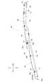
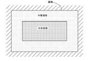
- the traveling route used in the seedling planting work (an example of field work) by this rice transplanterwill be described below. As shown in FIG. 15, the field is divided into an outer peripheral region in which the orbital travel route is set and a central region in which the reciprocating travel route is set. The rice transplanter first performs seedling planting work on the central region along the reciprocating travel route, and then performs seedling planting operation on the outer peripheral region along the circular travel route.
- FIG. 16shows a circuit traveling route.
- the orbital travel routeconsists of an orbital straight route that extends parallel to the field boundary (shore) and a direction change route that incorporates forward and reverse directions to connect the orbital straight routes.
- the code R1is assigned to the circular straight path
- the code R2is assigned to the direction change path.
- FIG. 17shows a round-trip travel route.
- the reciprocating travel pathconsists of a large number of reciprocating paths that are substantially parallel to each other and a turning path (U-turn path) that connects the reciprocating paths.
- R3is assigned to the reciprocating path
- the symbol R5is assigned to the turning path.
- reference numeral R4is assigned to the transition route for transitioning from the reciprocating travel route to the orbital travel route.
- the transition pathis similar to the turning path.
- the working width of the rice transplanteris indicated by reference numeral W, and the entrance / exit GA of the rice transplanter to the field is drawn with diagonal lines.
- FIG. 17shows a start guide route (with reference numeral R6) from the entrance / exit GA to the travel start position S of the reciprocating travel route.
- the turning path R5the turning path R2, the starting guide path R6, and the shifting path R4
- the rice transplantertravels without any work, so these routes are indicated by dotted lines.
- the circular straight route R1 and the round-trip route R3the rice transplanter travels while performing work, so these routes are shown by solid lines.
- Signals from the positioning unit 108, the automatic changeover switch 127, the traveling sensor group 128, and the work sensor group 129are input to the control unit 106, which forms the core of the control system of the rice transplanter.
- a control signalis output from the control unit 106 to the traveling equipment group 101A, the working equipment group 101B, the general-purpose terminal 109, and the notification unit 110.
- the automatic changeover switch 127is provided in the driving unit 120 and is a switch for selecting between an automatic traveling mode in which the aircraft 101 is automatically traveled and a manual traveling mode in which the aircraft 101 is manually traveled.
- the travel sensor group 128includes various sensors that detect states such as the steering angle, the operating position of the main shift lever 122 and the auxiliary shift lever 123, the vehicle speed, the engine speed, and the set values for them.
- the work sensor group 129includes various sensors that detect the state of the link mechanism 111, the seedling planting device 103, and the fertilizer application device 104, and set values for them.
- the traveling device group 101Aincludes, for example, a front wheel 112A and a continuously variable transmission 114.
- the steering angle of the front wheels 112Ais controlled based on the control signal from the control unit 106, and the vehicle speed is controlled by operating the continuously variable transmission 114.
- the travel route setting unit 164sets a travel route, which is a target travel route in automatic driving, and gives it to the automatic travel control unit 611.
- the amount of fertilizer to be applied to the corresponding field areais input.
- a fertilizer application amount of 40 kg / a or more and 100 kg / a or lessis input as a working value.
- the fertilizer application amount of 100 kg / ais input to the region where the sunlight is poor and the soil condition is poor, and the fertilizer application amount of 50 kg / a is input to the region where the sunlight is good and the soil condition is excellent.
- Appropriate values of fertilizer application amountare input for other areas according to the conditions.
- the amount of fertilizer appliedmay be determined according to the distribution of the yield of grains last year, or may be determined by the worker from experience, and is determined by an arbitrary method.
- "0" corresponding to the non-working valueis input as the fertilizer application amount to the section corresponding to the outside of the field.
- the work parameter setting unit 165reads the amount of fertilizer applied to the section corresponding to the position of the own vehicle when the machine 101 is working in the field, and determines the set value according to the read amount of fertilizer to apply fertilizer.
- the feeding mechanism 142 of the device 104is controlled to control the amount of fertilizer applied.
- the fertilizer application plan map 150is also used for determining whether or not the position of the own vehicle (the position of the aircraft 101) is in the field.
- the fertilizer application amountis input to the area inside the field, and “0” corresponding to the non-work value is input as the fertilizer application amount because the fertilizer application work is not performed in the area outside the field. Therefore, the own vehicle position determination unit 167 can determine whether the own vehicle position (position of the aircraft 101) is inside the field or outside the field by checking the fertilizer application plan map 150.
- the own vehicle position determination unit 167acquires the own vehicle position from the own vehicle position calculation unit 163, and reads out the fertilizer application amount input to the section of the fertilizer application plan map 150 corresponding to the own vehicle position. Then, when the read fertilizer application amount is "0", the own vehicle position determination unit 167 determines that the own vehicle position (position of the machine body 101) is outside the field.
- the non-working valueis not limited to "0", and may be a numerical value in an arbitrary range, an arbitrary character string, a blank, or the like.
- the own vehicle position determination unit 167can easily determine that the vehicle is traveling on the outer peripheral portion of the field, and notifies the automatic travel control unit 611 to that effect.
- the notification unit 110 or the likecan notify the fact. As a result, it is possible to take measures such as reducing the traveling speed by the automatic traveling control unit 611 in the automatic traveling and by the operation of the driver in the manual driving. As a result, the aircraft 101 can be easily avoided from obstacles.
- the warningis given when the own vehicle position determination unit 167 determines that the own vehicle position (position of the machine 101) is outside the field and the fertilizer application work is continued. You may be broken.
- the work control unit 162acquires the state of whether or not the fertilizer application work is in progress from the fertilizer application device 104, and transmits that fact to the notification unit 110 during the fertilizer application work. Then, in addition to receiving a notification from the own vehicle position determination unit 167 that the own vehicle position (position of the machine 101) is outside the field, the notification unit 110 indicates that fertilization work is being performed from the work control unit 162. Warn when notified.
- the rice transplantermay deviate from the field when replenishing seedlings or refueling, and the field is also moved.
- the problem of deviating from the fieldis when deviating from the field while performing fertilization work.
- a warningis given when replenishing seedlings, refueling, or moving a field, it is troublesome and may cause the necessary warning to be overlooked. Therefore, it is preferable that a warning is given when the person deviates from the field only during the fertilization work, which actually requires a warning.
- the fertilizer application plan map 150not only the fertilizer application plan map 150 but also any work plan map may be used. That is, it can be applied not only to rice transplanters but also to various work machines that perform work other than fertilization work.
- the work plan mapmesh-shaped sections are assumed corresponding to the work area, and work values for adjusting the amount of work are input to each section in the work area.
- the fertilizer application plan map 150corresponds to the field to be worked on. Therefore, the fertilizer application plan map 150 (work plan map) may be applied to any map which is map information indicating the position and coordinates of the field (work site). Such a map may be an existing general-purpose map. As a result, even if the determined own vehicle position deviates from the actual position due to a malfunction of the positioning unit 108 or the like, the rice transplanter is located inside or outside the field from the work instruction value of the fertilizer application plan map 150. You can decide whether to do it.
- the fertilizer application plan map 150may be shared with the yield map associated with the taste and yield acquired by the combine (harvester) that performs the harvesting work in the same field. Rice transplanters and combines work continuously on the same field. Therefore, it is preferable that the yield map generated by the combine and the fertilizer application plan map 150 used by the rice transplanter are associated with each other. This makes it possible to plan more systematic and precise farm work.
- the section of the yield map generated by the combinemay be the same as the section of the fertilization plan map 150 used by the rice transplanter, or may be smaller than the section of the fertilizer plan map 150.
- the work machine of the present inventionis not limited to a rice transplanter, but may be an agricultural work machine that performs work while traveling on a work site such as a tractor, and is applied to various work machines that perform work while traveling on a specific work site. You can also do it.
- Seedling planting device(working device) 11 Aircraft 12 Fertilizer application device (working device) 18 Driver's seat 22 Spare seedling stand frame (support frame, first support frame) 24 Support frame (first support frame) 26 Support frame (second support frame) 25 Positioning unit 27 Support frame (second support frame) 31 1st height change mechanism 32 2nd height change mechanism 36 Roof 38 Roof part 38a Front and rear drainage channels 38b Left and right drainage channels 38c Recesses 38d Rear 39 Roof parts 39a Front and rear drainage channels 39b Left and right drainage channels 39c Front 40a Recessions 49 Openings 50 consecutive passages 51 cushioning material 53 connecting mechanism 57 support mechanism A1 working position A2 non-working position 108A satellite positioning module 110 notification unit 150 fertilizer application plan map (work plan map) 166 Storage unit 167 Vehicle position determination unit 168 Map correction unit H11 1st work height H12 1st non-work height H21 2nd work height H22 2nd non-work height
Landscapes
- Engineering & Computer Science (AREA)
- Life Sciences & Earth Sciences (AREA)
- Mechanical Engineering (AREA)
- Environmental Sciences (AREA)
- Soil Sciences (AREA)
- Physics & Mathematics (AREA)
- Automation & Control Theory (AREA)
- General Physics & Mathematics (AREA)
- Remote Sensing (AREA)
- Radar, Positioning & Navigation (AREA)
- Aviation & Aerospace Engineering (AREA)
- Chemical & Material Sciences (AREA)
- Combustion & Propulsion (AREA)
- Transportation (AREA)
- Body Structure For Vehicles (AREA)
- Fertilizing (AREA)
Abstract
Description
Translated fromJapanese本発明は、乗用型田植機や乗用型直播機等の作業機に関する。The present invention relates to a working machine such as a riding type rice transplanter and a riding type direct seeding machine.
作業機の一例である乗用型田植機では、特許文献1に開示されているように、機体から上側に延出された支持フレームに、合成樹脂製の屋根が支持されて、屋根により運転座席を含む機体の上方を覆うように構成されたものがある。In a passenger-type rice transplanter, which is an example of a working machine, as disclosed in Patent Document 1, a synthetic resin roof is supported by a support frame extending upward from the machine body, and the driver's seat is provided by the roof. Some are configured to cover the top of the including aircraft.
また、特許文献2に開示されるように、作業地である圃場を作業走行する作業機(農作業機)には、あらかじめ設定された走行経路を自動走行しながら作業を行うものがある。この様な作業機は、衛星信号により走行中の自車位置を特定しながら、あらかじめ設定された作業地の走行経路を走行する。Further, as disclosed in
さらに、特許文献3に示すように、作業機には、施肥計画マップを作成し、作業地内の各領域に施肥する肥料の量を施肥計画マップに基づいて決定する作業機もある。Further, as shown in Patent Document 3, there is also a working machine that creates a fertilizer application plan map and determines the amount of fertilizer to be applied to each area in the work site based on the fertilizer application plan map.
特許文献1のように、屋根により運転座席を含む機体の上方を覆うように構成すると、屋根が比較的大きなものになる。これによって、例えば強風が屋根の下側に吹き込んだ場合、屋根が持ち上げられるような状態となるので、屋根の破損防止の面で改善の余地がある。As in Patent Document 1, if the roof is configured to cover the upper part of the aircraft including the driver's seat, the roof becomes relatively large. As a result, for example, when a strong wind blows under the roof, the roof is lifted, so there is room for improvement in terms of preventing damage to the roof.
本発明は、運転座席を含む機体の上方を覆う屋根が備えられた作業機において、強風が屋根の下側に吹き込んだ場合の屋根の破損防止を図ることを第1の目的としている。The first object of the present invention is to prevent damage to the roof when a strong wind blows under the roof in a working machine provided with a roof that covers the upper part of the machine body including the driver's seat.
作業機が目的の作業地から逸脱すると、作業機が畦等と衝突したり、隣接する作業地に不要な作業を行ってしまう場合がある。そのため、作業機が作業地内に存在するか否かをより精度良く検知することが求められている。If the work machine deviates from the target work place, the work machine may collide with ridges or perform unnecessary work on the adjacent work place. Therefore, it is required to more accurately detect whether or not the work machine exists in the work site.
本発明は、作業機が作業地内に存在するか否かを精度良く検知すること第2の目的とする。The second object of the present invention is to accurately detect whether or not the working machine exists in the working area.
上記第1の目的を達成するために、本発明の一実施形態に係る作業機は、機体に支持された運転座席と、前記機体から上側に延出された支持フレームと、前記運転座席を含む前記機体の上方を覆うように、前記支持フレームに支持された屋根とが備えられ、前記屋根に、前記屋根の上面に沿った方向に向いた開口部と、前記屋根に対して下側の領域と前記開口部とを連通させる連通路とが設けられている。In order to achieve the first object, the working machine according to the embodiment of the present invention includes a driver's seat supported by the machine body, a support frame extending upward from the machine body, and the driver's seat. A roof supported by the support frame is provided so as to cover the upper part of the airframe, and the roof has an opening oriented in a direction along the upper surface of the roof and an area below the roof. A communication passage is provided to communicate the opening with the opening.
このような構成によると、例えば強風が屋根の下側に吹き込んだ場合、強風の一部が屋根の連通路を通り開口部から屋根の上側に抜け出る状態を得ることができる。これにより、屋根が持ち上げられるような状態が弱められるのであり、屋根の破損防止の面で有利である。According to such a configuration, for example, when a strong wind blows into the lower side of the roof, it is possible to obtain a state in which a part of the strong wind passes through the continuous passage of the roof and escapes from the opening to the upper side of the roof. As a result, the state in which the roof is lifted is weakened, which is advantageous in terms of preventing damage to the roof.
このような構成によると、屋根の開口部が、屋根の上面に沿った方向に向いており、上に向いていない。これにより、雨天において、雨水が屋根の開口部に入り込む可能性は小さく、雨水が屋根の開口部から連通路を通って機体に落ちるようなことは少ない。According to such a configuration, the opening of the roof faces in the direction along the upper surface of the roof, not upward. As a result, in rainy weather, it is unlikely that rainwater will enter the opening of the roof, and it is unlikely that rainwater will fall from the opening of the roof through the passageway to the aircraft.
本発明において、側面視で、前記屋根の前部が前記屋根の後部よりも低くなる前傾姿勢となるように、前記屋根が前記支持フレームに支持され、前記開口部が前方向に向いていると好適である。In the present invention, the roof is supported by the support frame and the opening faces forward so that the front portion of the roof is in a forward leaning posture lower than the rear portion of the roof in a side view. Is suitable.
このような構成によると、例えば強風が前側から機体に向けて吹いた場合、屋根が前傾姿勢であることによって、屋根が下側に押し付けられるような状態となる点、及び、強風の一部が屋根の開口部から連通路を通り屋根の下側に抜け出る状態を得ることができる点により、屋根の破損防止の面で有利である。According to such a configuration, for example, when a strong wind blows from the front side toward the aircraft, the roof is in a forward leaning posture so that the roof is pressed downward, and a part of the strong wind. It is advantageous in terms of preventing damage to the roof, because it is possible to obtain a state in which the roof escapes from the opening of the roof through a continuous passage to the lower side of the roof.
例えば強風が後側から機体に向けて吹いた場合、屋根が前傾姿勢であることにより、強風が屋根の下側に吹き込む状態となる。しかしながら、強風の一部が屋根の連通路を通り開口部から屋根の上側に抜け出る状態を得ることができるので、屋根が持ち上げられるような状態が弱められ、屋根の破損防止の面で有利である。
この場合、屋根の開口部が屋根の上面に沿った方向である前方向に向いていることにより、前述のように強風が後側から機体に向けて吹いた場合、強風の一部が屋根の開口部から前方向に円滑に抜け出るようになるので、屋根の破損防止の面で有利である。For example, when a strong wind blows from the rear side toward the aircraft, the roof is in a forward leaning posture, so that the strong wind blows into the lower side of the roof. However, since it is possible to obtain a state in which a part of the strong wind passes through the continuous passage of the roof and escapes from the opening to the upper side of the roof, the state in which the roof is lifted is weakened, which is advantageous in terms of preventing damage to the roof. ..
In this case, since the opening of the roof faces the front direction, which is the direction along the upper surface of the roof, when a strong wind blows from the rear side toward the aircraft as described above, a part of the strong wind is on the roof. Since it can be smoothly pulled out from the opening in the forward direction, it is advantageous in terms of preventing damage to the roof.
本発明において、分割された複数個の屋根部分が、前後方向に沿って並んで配置されるように、前記屋根に設けられ、前後方向で隣接する前記屋根部分において、前の前記屋根部分の後部が、後の前記屋根部分の前部に対して下側に位置するように、前の前記屋根部分の後部と後の前記屋根部分の前部とが重ねて配置され、前の前記屋根部分の後部と後の前記屋根部分の前部とが重なる部分において、前の前記屋根部分の後部と後の前記屋根部分の前部とが上下方向に沿って離れる部分が設けられて、前記開口部と前記連通路とが設けられていると好適である。In the present invention, a plurality of divided roof portions are provided on the roof so as to be arranged side by side along the front-rear direction, and in the roof portions adjacent in the front-rear direction, the rear portion of the front roof portion. Is arranged so that the rear portion of the front roof portion and the front portion of the rear roof portion are overlapped with each other so as to be located below the front portion of the rear roof portion. In the portion where the rear portion and the front portion of the rear roof portion overlap, a portion is provided in which the rear portion of the front roof portion and the front portion of the rear roof portion are separated from each other in the vertical direction. It is preferable that the connecting passage is provided.
このような構成によると、複数個の分割された屋根部分が設けられており、1個の屋根部分は比較的小さいものとなるので、屋根部分は、取り扱いが容易なものとなり、生産も容易なものとなる。これにより、複数個の屋根部分に分割されていない大きな屋根を取り扱う構成に比べて、生産性の向上の面で有利である。According to such a configuration, a plurality of divided roof portions are provided, and one roof portion is relatively small, so that the roof portion is easy to handle and easy to produce. It becomes a thing. This is advantageous in terms of improving productivity as compared with a configuration in which a large roof that is not divided into a plurality of roof portions is handled.
このような構成によると、前述のように複数個の分割された屋根部分が設けられた場合に、前後方向で隣接する屋根部分において、前の屋根部分の後部と後の屋根部分の前部とが重ねられ、前の屋根部分の後部と後の屋根部分の前部とが上下方向に沿って離れる部分が設けられて、屋根の開口部及び連通路が設けられている。
この場合、前の屋根部分の後部が後の屋根部分の前部の下側に位置するように重ねられるので、前方向に向く屋根の開口部が容易に構成される。According to such a configuration, when a plurality of divided roof portions are provided as described above, in the roof portions adjacent to each other in the front-rear direction, the rear portion of the front roof portion and the front portion of the rear roof portion , And a portion is provided in which the rear portion of the front roof portion and the front portion of the rear roof portion are separated from each other in the vertical direction, and an opening of the roof and a connecting passage are provided.
In this case, since the rear portion of the front roof portion is overlapped so as to be located below the front portion of the rear roof portion, the opening of the roof facing forward is easily constructed.
前述のように、前の屋根部分の後部が後の屋根部分の前部の下側に位置するように重ねられた場合、屋根が前傾状態に支持されているので、前の屋根部分の後部と後の屋根部分の前部との間に、雨水が入っても、雨水が前の屋根部分の後端部に達して機体に落ちるようなことは少ない。As mentioned above, when the rear part of the front roof part is stacked so as to be located below the front part of the rear roof part, the roof is supported in a forward leaning state, so that the rear part of the front roof part is supported. Even if rainwater enters between the front part of the roof part and the front part of the rear roof part, it is unlikely that the rainwater will reach the rear end part of the front roof part and fall on the aircraft.
本発明において、前の前記屋根部分の後部と後の前記屋根部分の前部との間に、緩衝材が設けられていると好適である。In the present invention, it is preferable that a cushioning material is provided between the rear portion of the front roof portion and the front portion of the rear roof portion.
このような構成によると、走行時の機体の振動等により、前の屋根部分や後の屋根部分が振動しても、前の屋根部分の後部と後の屋根部分の前部との衝突が、緩衝材により抑えられるので、前の屋根部分の後部と後の屋根部分の前部との衝突音が抑えられる。According to such a configuration, even if the front roof part and the rear roof part vibrate due to the vibration of the aircraft during traveling, the collision between the rear part of the front roof part and the front part of the rear roof part can occur. Since it is suppressed by the cushioning material, the collision noise between the rear part of the front roof part and the front part of the rear roof part is suppressed.
本発明において、前記屋根の前部及び後部の一方を支持する第1の前記支持フレームと、前記屋根の前部及び後部の他方を支持する第2の前記支持フレームとが設けられ、航法衛星の測位信号に基づいて前記機体の位置を示す測位データを出力する測位ユニットが、側面視で前記屋根の前部及び後部の一方と同じ高さに位置するように、第1の前記支持フレームに支持されていると好適である。In the present invention, a first support frame that supports one of the front and rear parts of the roof and a second support frame that supports the other of the front and rear parts of the roof are provided, and the navigation satellite is provided with a second support frame. A positioning unit that outputs positioning data indicating the position of the aircraft based on the positioning signal is supported by the first support frame so as to be located at the same height as one of the front part and the rear part of the roof in a side view. It is preferable that the roof is used.
作業機では、航法衛星の測位信号に基づいて機体の位置を示す測位データを出力する測位ユニットを装備して、機体の位置をディスプレイに表示したり、測位データに基づいて機体の自動運転が行われるように構成することがある。The work equipment is equipped with a positioning unit that outputs positioning data indicating the position of the aircraft based on the positioning signal of the navigation satellite, displays the position of the aircraft on the display, and automatically operates the aircraft based on the positioning data. May be configured to be
このような構成によると、屋根の前部及び後部の一方及び他方を支持する第1及び第2の支持フレームにおいて、測位ユニットが第1の支持フレームに支持されるので、第1の支持フレームが屋根の支持用と測位ユニットの支持用に兼用されて、構造の簡素化の面で有利になる。According to such a configuration, in the first and second support frames supporting one and the other of the front part and the rear part of the roof, the positioning unit is supported by the first support frame, so that the first support frame can be used. It is used for both roof support and positioning unit support, which is advantageous in terms of structural simplification.
このような構成によると、測位ユニットが側面視で屋根の前部及び後部の一方と同じ高さに位置するように支持されるので、測位ユニットが屋根の前部及び後部の一方から上側や下側に大きく突出することがなく、測位ユニットと屋根とがコンパクトに支持される。According to such a configuration, the positioning unit is supported so as to be positioned at the same height as one of the front part and the rear part of the roof in a side view, so that the positioning unit is above or below one of the front part and the rear part of the roof. The positioning unit and the roof are compactly supported without protruding significantly to the side.
本発明において、平面視で前記測位ユニットが入り込み可能な凹部が、前記屋根の前部及び後部の一方に設けられていると好適である。In the present invention, it is preferable that a recess into which the positioning unit can enter is provided in one of the front portion and the rear portion of the roof in a plan view.
このような構成によると、測位ユニットが屋根の前部から前側に大きく突出することがないので(測位ユニットが屋根の後部から後側に大きく突出することがないので)、測位ユニットと屋根とがコンパクトに支持される。With such a configuration, the positioning unit and the roof do not protrude significantly from the front of the roof to the front (because the positioning unit does not protrude significantly from the rear to the rear of the roof). It is supported compactly.
本発明において、前記凹部の左右幅が、前記測位ユニットの左右幅よりも大きなものに設定されていると好適である。In the present invention, it is preferable that the left-right width of the recess is set to be larger than the left-right width of the positioning unit.
作業機では、測位ユニットを装備することに加えて、通信用等の別の機器を装備することがある。
このような構成によると、屋根の凹部の左右幅が測位ユニットの左右幅よりも大きなものに設定されているので、測位ユニットに加えて別の機器を、屋根の凹部に入り込むように支持フレームに支持させることが容易に行える。In addition to being equipped with a positioning unit, the work equipment may be equipped with another device for communication or the like.
According to such a configuration, the left-right width of the recess of the roof is set to be larger than the left-right width of the positioning unit, so that another device in addition to the positioning unit is placed in the support frame so as to enter the recess of the roof. It can be easily supported.
本発明において、第1の前記支持フレームと前記屋根とを連結及び解除可能な連結機構と、第1の前記支持フレームと前記屋根とが前記連結機構により連結可能になる作業位置、並びに、前記連結機構の解除状態で前記測位ユニットから前後方向に沿って離れた非作業位置に亘って、前記屋根を位置変更可能に第2の前記支持フレームに支持可能な支持機構と、前記屋根が前記作業位置に位置した状態で、第1の前記支持フレームと前記屋根とが前記連結機構により連結可能な第1作業高さ、並びに、前記第1作業高さよりも低い第1非作業高さに亘って、第1の前記支持フレームを高さ変更可能な第1高さ変更機構と、前記屋根が前記作業位置に位置した状態で、第1の前記支持フレームと前記屋根とが前記連結機構により連結可能な第2作業高さ、並びに、前記第2作業高さよりも低い第2非作業高さに亘って、第2の前記支持フレームを高さ変更可能な第2高さ変更機構とが備えられていると好適である。In the present invention, a connecting mechanism capable of connecting and disconnecting the first support frame and the roof, a working position where the first support frame and the roof can be connected by the connecting mechanism, and the connection. A support mechanism capable of repositioning the roof over a non-working position separated from the positioning unit in the front-rear direction in the released state of the mechanism, and a support mechanism capable of supporting the roof on the second support frame, and the roof being the working position. The first working height at which the first support frame and the roof can be connected by the connecting mechanism and the first non-working height lower than the first working height in the state of being located at The first height changing mechanism capable of changing the height of the first support frame and the first support frame and the roof can be connected by the connecting mechanism while the roof is located at the working position. A second height changing mechanism capable of changing the height of the second support frame over a second working height and a second non-working height lower than the second working height is provided. Is suitable.
このような構成によると、例えば作業機をトラックの荷台に載せて運搬する場合や、作業機を倉庫等に保管する場合、以下の説明のような操作を行うことにより、第1及び第2の支持フレーム、測位ユニットや屋根の高さを低くすることができる。According to such a configuration, for example, when the work machine is carried on a truck bed or when the work machine is stored in a warehouse or the like, the first and second operations are performed as described below. The height of the support frame, positioning unit and roof can be lowered.
作業機により通常の作業を行う場合、第1及び第2の支持フレームは第1作業高さ及び第2作業高さに設定され、屋根は、作業位置に設定されて、連結機構により屋根が第1の支持フレームに連結されている。When performing normal work with a work machine, the first and second support frames are set to the first work height and the second work height, the roof is set to the work position, and the roof is set to the first by the connecting mechanism. It is connected to the support frame of 1.
前述の状態において、連結機構が解除状態に操作されて、屋根が第1の支持フレームから外される。つまり、第1の支持フレームの高さを、第1高さ変更機構により第1作業高さから、第1作業高さよりも低い第1非作業高さに変更するのであり、第1の支持フレームに支持された測位ユニットも、第1の支持フレームと一緒に低い位置に設定される。In the above-mentioned state, the connecting mechanism is operated in the released state, and the roof is removed from the first support frame. That is, the height of the first support frame is changed from the first working height to the first non-working height lower than the first working height by the first height changing mechanism, and the first supporting frame The positioning unit supported by the above is also set at a low position together with the first support frame.
また、第2の支持フレームの高さを、第2高さ変更機構により第2作業高さから、第2作業高さよりも低い第2非作業高さに変更するのであり、第2の支持フレームに支持された屋根も、第2の支持フレームと一緒に低い位置に設定される。
この際、屋根を支持機構により非作業位置に設定しておくことにより、屋根が第1の支持フレームから離れる。Further, the height of the second support frame is changed from the second working height to the second non-working height lower than the second working height by the second height changing mechanism, and the second supporting frame is changed. The roof supported by the roof is also set at a low position together with the second support frame.
At this time, by setting the roof to a non-working position by the support mechanism, the roof is separated from the first support frame.
以上のように、第1及び第2の支持フレーム、測位ユニットや屋根の高さを低くすることができるのであり、例えば作業機をトラックの荷台に載せての運搬や、作業機の倉庫等での保管が、無理なく行える。As described above, the heights of the first and second support frames, the positioning unit, and the roof can be lowered. For example, in the case of transporting a work machine on a truck bed, carrying a work machine in a warehouse, or the like. Can be stored without difficulty.
本発明において、断面凹状の右の前後排水路が、前記屋根の上面の右部に前後方向に沿って設けられ、断面凹状の左の前後排水路が、前記屋根の上面の左部に前後方向に沿って設けられ、断面凹状の複数の左右排水路が、前記屋根の上面に左右方向に沿って設けられて、前記前後排水路に接続され、雨水が右及び左の前記前後排水路から排水されると好適である。In the present invention, a right front-rear drainage channel having a concave cross section is provided along the front-rear direction on the right portion of the upper surface of the roof, and a left front-rear drainage channel having a concave cross section is provided on the left portion of the upper surface of the roof in the front-rear direction. A plurality of left and right drainage channels having a concave cross section are provided along the left and right directions on the upper surface of the roof and are connected to the front and rear drainage channels, and rainwater is drained from the front and rear drainage channels on the right and left sides. It is preferable to be done.
このような構成によると、屋根の上面に前後排水路及び左右排水路が設けられ、雨水は主に前後排水路から排水される。
この場合、断面凹状の前後排水路及び断面凹状の左右排水路が、互いに交差するように屋根の上面に配置されるので、前後排水路及び左右排水路が屋根の補強部として機能することになり、屋根の剛性を向上させることができる。According to such a configuration, front and rear drainage channels and left and right drainage channels are provided on the upper surface of the roof, and rainwater is mainly drained from the front and rear drainage channels.
In this case, since the front and rear drainage channels having a concave cross section and the left and right drainage channels having a concave cross section are arranged on the upper surface of the roof so as to intersect each other, the front and rear drainage channels and the left and right drainage channels function as reinforcing portions of the roof. , The rigidity of the roof can be improved.
本発明において、作業装置が前記機体の後部に支持され、雨水が右及び左の前記前後排水路の前部から排水されると好適である。In the present invention, it is preferable that the working device is supported by the rear part of the machine body and rainwater is drained from the front part of the front and rear drainage channels on the right and left sides.
乗用型田植機や乗用型直播機等の作業機では、苗植付装置や播種装置、施肥装置等の作業装置が機体に後部に支持されることが多い。
上記構成によると、雨水が屋根の右及び左の前後排水路の前部から排水されるので、前後排水路からの雨水が作業装置に掛かることは少ない。
雨水が屋根の右及び左の前後排水路の前部から排水されることにより、屋根の前部の左右中央部から落ちる雨水が少なくなるので、運転座席の作業者の前方視界の確保の面で有利である。In working machines such as riding-type rice transplanters and riding-type direct sowing machines, working devices such as seedling planting devices, sowing devices, and fertilizer application devices are often supported by the machine body at the rear.
According to the above configuration, since rainwater is drained from the front part of the front and rear drainage channels on the right and left sides of the roof, it is unlikely that rainwater from the front and rear drainage channels will be applied to the work equipment.
By draining rainwater from the front of the front and rear drainage channels on the right and left of the roof, less rainwater falls from the left and right center of the front of the roof, so in terms of ensuring the front visibility of the driver's seat worker. It is advantageous.
上記第2の目的を達成するために、本発明の一実施形態に係る作業機は、作業指示値に応じて作業地を作業走行する作業機であって、衛星からの衛星信号を受信する衛星アンテナと、前記衛星信号に基づいて自車位置に対応する測位データを出力する衛星測位モジュールと、前記作業地に対応付けられてメッシュ状に区切られた区画毎に前記作業指示値が入力される作業計画マップを保存する記憶部と、前記自車位置に対応する前記区画に入力された前記作業指示値に応じて前記自車位置が前記作業地内であるか否かを判定する自車位置判定部とを備える。In order to achieve the second object, the work machine according to the embodiment of the present invention is a work machine that runs on the work site according to the work instruction value, and is a satellite that receives a satellite signal from the satellite. The work instruction value is input to each of an antenna, a satellite positioning module that outputs positioning data corresponding to the position of the own vehicle based on the satellite signal, and a mesh-shaped section associated with the work site. Own vehicle position determination for determining whether or not the own vehicle position is within the work site according to the storage unit for storing the work plan map and the work instruction value input to the section corresponding to the own vehicle position. It has a part.
衛星からの衛星信号に基づいて自車位置を特定する作業機は、作業地マップ等と自車位置とを対応付けて作業地中の自車位置を確認しながら作業走行する。このような作業機においても、作業地マップの不具合や衛星アンテナ等の測位ユニットの誤動作、自車位置の検出誤差等により、作業機は作業地を逸脱して走行する場合もある。The work machine that identifies the position of the own vehicle based on the satellite signal from the satellite runs while checking the position of the own vehicle in the work area by associating the work area map and the position of the own vehicle with the position of the own vehicle. Even in such a work machine, the work machine may deviate from the work place due to a malfunction of the work place map, a malfunction of a positioning unit such as a satellite antenna, a detection error of the position of the own vehicle, or the like.
上記構成では、作業計画マップのいずれの区画に自車位置が対応するかを確認し、その区画に入力された作業指示値から、自車位置が作業地内であるか否かを判定する。そのため、作業地マップ等に対応した自車位置の確認に加えて、作業計画マップにおける自車位置に対応する区画に入力された作業指示値に基づいて、自車位置が作業地内であるか否かを判定することにより、自車位置が作業地内であるか否かを二重に確認できる。その結果、作業地マップに不具合がある場合や、自車位置に多少の誤差がある場合であっても、自車位置が作業地内であるか否かを精度良く確認することができる。In the above configuration, it is confirmed which section of the work plan map the own vehicle position corresponds to, and whether or not the own vehicle position is within the work area is determined from the work instruction value input to that section. Therefore, in addition to confirming the position of the own vehicle corresponding to the work site map, whether or not the position of the own vehicle is within the work area based on the work instruction value input to the section corresponding to the position of the own vehicle in the work plan map. By determining whether or not the vehicle is located within the work area, it is possible to double-check whether or not the vehicle is located within the work area. As a result, even if there is a problem in the work area map or there is some error in the position of the own vehicle, it is possible to accurately confirm whether or not the position of the own vehicle is within the work area.
また、前記作業指示値は作業を行わないための非作業値を含み、前記自車位置判定部は、前記作業指示値が前記非作業値である場合に前記自車位置が前記作業地外であると判定しても良い。Further, the work instruction value includes a non-work value for not performing the work, and the own vehicle position determination unit indicates that the own vehicle position is outside the work area when the work instruction value is the non-work value. It may be determined that there is.
このような構成により、自車位置が作業地外であると判定される作業指示値が明確となり、自車位置が作業地内であるか否かの判定をより容易に行うことができ、自車位置が作業地内であるか否かを精度良く確認することができる。With such a configuration, the work instruction value for determining that the vehicle position is outside the work area is clarified, and it is possible to more easily determine whether or not the vehicle position is inside the work area. It is possible to accurately confirm whether or not the position is within the work area.
また、前記作業計画マップを修正するマップ修正部を備え、作業を行う前記作業指示値は前記非作業値より大きい所定の範囲の作業値であり、前記マップ修正部は、作業地の外周位置が示される作業地マップを参照可能であり、前記マップ修正部は、前記外周位置に対応する前記区画の前記作業値を前記非作業値と前記作業値との間の値に修正しても良い。Further, a map correction unit for modifying the work plan map is provided, and the work instruction value for performing the work is a work value in a predetermined range larger than the non-work value. The work area map shown can be referred to, and the map correction unit may correct the work value of the section corresponding to the outer peripheral position to a value between the non-work value and the work value.
このような構成により、自車が畔等の作業地の外周領域の近傍を走行していることが、自車位置に対応する区画に入力された作業指示値から容易に確認される。その結果、畔等の作業地の外周領域の近傍を走行する際に適切な走行を行う契機とすることができ、作業地から逸脱することを容易に回避することが可能となる。With such a configuration, it can be easily confirmed from the work instruction value input to the section corresponding to the position of the own vehicle that the own vehicle is traveling in the vicinity of the outer peripheral region of the work area such as the shore. As a result, when traveling in the vicinity of the outer peripheral region of the work site such as a shore, it can be used as an opportunity to perform appropriate travel, and it is possible to easily avoid deviating from the work site.
また、前記自車位置判定部により前記自車位置が前記作業地外であると判定された場合に警告を報知する報知部を備えることが好ましい。Further, it is preferable to provide a notification unit that notifies a warning when the vehicle position is determined to be outside the work site by the vehicle position determination unit.
このような構成により、運転者や作業者は、自車位置が作業地外であることを認知でき、適切な対応を行う契機とすることができる。With such a configuration, the driver and the worker can recognize that the position of the own vehicle is outside the work area, and can be an opportunity to take an appropriate response.
また、前記自車位置判定部により前記自車位置が前記作業地外であると判定され、かつ作業状態である場合に警告を報知する報知部を備えても良い。Further, a notification unit may be provided to notify a warning when the vehicle position is determined by the vehicle position determination unit to be outside the work area and the vehicle is in a working state.
作業走行中は、資材や燃料の補給等のため、作業地を逸脱して走行する場合もあり、この走行は問題がない。作業地外を走行して問題となるのは、作業地外を走行しているにもかかわらず、作業が継続されている場合である。作業地外で作業を行うと、作業装置が畔等に衝突して破損したり、隣接する作業地等に不適切な作業を行ってしまったりする。During work driving, there may be cases where the vehicle deviates from the work site due to replenishment of materials and fuel, etc., and this driving is not a problem. The problem of traveling outside the work area is when the work is continued even though the vehicle is traveling outside the work area. If the work is performed outside the work area, the work device may collide with the shore or the like and be damaged, or the work may be inappropriately performed on the adjacent work area or the like.
上記構成によると、作業走行しながら作業地を逸脱して初めて警告が行われるため、不要な警告を抑制し、より適切な警告のみを行うことができる。その結果、適切な警告に応じて、適切な対処を行うことができ、効率的に作業走行を行うことができる。According to the above configuration, since the warning is given only after deviating from the work place while working, it is possible to suppress unnecessary warnings and give only more appropriate warnings. As a result, it is possible to take appropriate measures in response to an appropriate warning, and it is possible to carry out work traveling efficiently.
また、前記作業指示値には、所定の基準作業値が定められ、前記警告が報知された後、作業状態が継続する場合は、前記基準作業値で作業を行っても良い。Further, if a predetermined reference work value is set for the work instruction value and the work state continues after the warning is notified, the work may be performed with the reference work value.
作業地を逸脱しても作業走行を継続する必要がある状況は、あらかじめ決まった特定の作業を行う場合が多い。上記構成によると、このような特定の作業における基準作業値をあらかじめ定めておき、作業地を逸脱して作業走行する場合は、自動的に基準作業値にて作業を行うことができるため、効率的に作業走行を行うことができる。In situations where it is necessary to continue working even after deviating from the work site, it is often the case that specific work is performed in advance. According to the above configuration, the standard work value for such a specific work is set in advance, and when the work deviates from the work site and the work is carried out, the work can be automatically performed at the standard work value, which is efficient. It is possible to carry out work running.
また、前記作業走行に係る作業は施肥作業であり、前記作業指示値は施肥する肥料の量であっても良い。Further, the work related to the work running is a fertilizer application work, and the work instruction value may be the amount of fertilizer to be fertilized.
このような構成により、施肥作業を行う作業走行においても、自車位置が作業地内であるかの判定を精度良く行うことができる。With such a configuration, it is possible to accurately determine whether or not the position of the own vehicle is within the work area even during work running where fertilization work is performed.
(実施形態1)
図1~図13に、作業機の一例である乗用型田植機が示されている。図1~図13において、Fは前方向を示し、Bは後方向を示し、Uは上方向を示し、Dは下方向を示し、Rは右方向を示し、Lは左方向を示している。(Embodiment 1)
1 to 13 show a passenger-type rice transplanter, which is an example of a working machine. In FIGS. 1 to 13, F indicates a forward direction, B indicates a backward direction, U indicates an upward direction, D indicates a downward direction, R indicates a right direction, and L indicates a left direction. ..
(乗用型田植機の全体構成)
図1及び図2に示すように、乗用型田植機は、右及び左の前輪1、右及び左の後輪2を備えた機体11の後部に、リンク機構3及びリンク機構3を昇降操作する油圧シリンダ4が備えられ、リンク機構3の後部に苗植付装置5(作業装置に相当)が支持されて、苗植付装置5が機体11の後部に支持されている。(Overall configuration of passenger rice transplanter)
As shown in FIGS. 1 and 2, the passenger-type rice transplanter moves the link mechanism 3 and the link mechanism 3 up and down to the rear part of the
苗植付装置5に、左右方向に所定間隔を置いて配置された植付伝動ケース6、植付伝動ケース6の右部及び左部に回転可能に支持された回転ケース7、回転ケース7の両端に支持された植付アーム8、フロート9、苗のせ台10等が設けられている。A
機体11の後部及び苗植付装置5に亘って、施肥装置12(作業装置に相当)が支持されており、施肥装置12に、ホッパー13、繰り出し部14、ブロア15、作溝器16及びホース17等が設けられている。A fertilizer application device 12 (corresponding to a work device) is supported over the rear part of the
運転座席18が、機体11の後部に支持されている。施肥装置12において、機体11における運転座席18の後側の部分に、肥料を貯留するホッパー13及び繰り出し部14が設けられており、繰り出し部14の左の横外側にブロア15が設けられている。フロート9に作溝器16が取り付けられており、繰り出し部14と作溝器16とに亘ってホース17が接続されている。The driver's
苗植付装置5において、苗のせ台10が往復横送り駆動されながら、植付アーム8(回転ケース7)が回転駆動されるのであり、植付アーム8が苗のせ台10の下部から苗を取り出して田面に植え付ける。In the
施肥装置12において、ホッパー13の肥料が繰り出し部14により繰り出されて、ブロア15の搬送風によりホース17を通って作溝器16に供給されるのであり、作溝器16により田面に溝が形成されながら、作溝器16から田面の溝に肥料が供給される。In the
(機体の前部の構成)
図1,2,3に示すように、機体11の前部に、エンジン(図示せず)が支持され、エンジンを覆うボンネット19が設けられており、前輪1を操向操作する操縦ハンドル20がボンネット19の後部に設けられている。ボンネット19の右側及び左側に、乗降用の右及び左のステップ21が設けられている。(Structure of the front part of the aircraft)
As shown in FIGS. 1, 2 and 3, an engine (not shown) is supported at the front portion of the
右及び左の予備苗のせ台フレーム22(第1の支持フレームに相当)が、機体11の前部の下部に連結されて横外側に延出され、右及び左のステップ21の横外側を上側に延出されている。予備苗のせ台フレーム22は、側面視でアーチ状(二股状)に構成されており、3個の予備苗のせ台23が予備苗のせ台フレーム22に支持されている。The right and left spare seedling cradle frames 22 (corresponding to the first support frame) are connected to the lower part of the front part of the
3個の予備苗のせ台23のうち、中央の予備苗のせ台23が予備苗のせ台フレーム22に支持されており、前の予備苗のせ台23が中央の予備苗のせ台23の前部に前後方向に揺動可能に支持され、後の予備苗のせ台23が中央の予備苗のせ台23の後部に前後方向に揺動可能に支持されている。Of the three spare seedling pedestals 23, the central
図1,2,3に示す状態は、中央の予備苗のせ台23に対して、前の予備苗のせ台23が後側に操作され、後の予備苗のせ台23が前側に操作されて、中央の予備苗のせ台23の上部に前及び後の予備苗のせ台23が積み重ねられた状態である。In the state shown in FIGS. 1, 2 and 3, the front spare seedling stand 23 is operated to the rear side and the rear spare seedling stand 23 is operated to the front side with respect to the center
図1,2,3に示す状態から、中央の予備苗のせ台23に対して、前の予備苗のせ台23が前側に操作され、後の予備苗のせ台23が後側に操作されることにより、3個の予備苗のせ台23が一列状に展開された状態に設定することができる。From the state shown in FIGS. 1, 2 and 3, the front
(機体の前部の第1の支持フレームの構成)
図1~図4に示すように、正面視でアーチ状の支持フレーム24(第1の支持フレームに相当)が設けられている。支持フレーム24は、丸パイプが折り曲げられて構成されており、左右方向に沿った横向き部24a、右及び左の縦向き部24b、右及び左の前後向き部24cが設けられている。(Structure of the first support frame at the front of the aircraft)
As shown in FIGS. 1 to 4, an arch-shaped support frame 24 (corresponding to the first support frame) is provided in a front view. The
右及び左の予備苗のせ台フレーム22の上部に、チャンネル状のブラケット22aが連結されており、支持フレーム24の前後向き部24cの端部が、左右方向に沿った軸芯P1周りに揺動可能に、予備苗のせ台フレーム22のブラケット22aに支持されている。A channel-shaped
図1,2,3,11に示す状態は、予備苗のせ台フレーム22のブラケット22aに対して、支持フレーム24(縦向き部24b)が上側に向いた状態であり、予備苗のせ台フレーム22及び支持フレーム24が第1作業高さH11に設定された状態である。予備苗のせ台フレーム22のブラケット22aと支持フレーム24の前後向き部24cとに亘って、固定部材(図示せず)を取り付けることにより、支持フレーム24を第1作業高さH11で固定することができる。In the states shown in FIGS. 1, 2, 3 and 11, the support frame 24 (
固定部材を取り外して、支持フレーム24を軸芯P1周りに後側に揺動させることによって、図12及び図13に示すように、支持フレーム24の縦向き部24bが下側に向けて、予備苗のせ台フレーム22及び支持フレーム24を、第1作業高さH11よりも低い第1非作業高さH12に設定することができる。By removing the fixing member and swinging the
第1非作業高さH12において、支持フレーム24の縦向き部24bが予備苗のせ台フレーム22の後部に当たるので、支持フレーム24は図12及び図13に示す状態から前側に揺動することはできない。取り外した固定部材を、予備苗のせ台フレーム22のブラケット22aと支持フレーム24の前後向き部24cとに亘って取り付けることにより、支持フレーム24を第1非作業高さH12で固定することができる。At the first non-working height H12, since the
以上のように、予備苗のせ台フレーム22及び支持フレーム24を、第1作業高さH11及び第1非作業高さH12に亘って高さ変更可能な第1高さ変更機構31が設けられている。第1高さ変更機構31に、予備苗のせ台フレーム22のブラケット22a、支持フレーム24の前後向き部24c及び固定部材等が設けられている。As described above, the first
(測位ユニットの構成)
図1~図4に示すように、支持フレーム24の横向き部24aの左右中央部に、測位ユニット25が取り付けられている。前述の(機体の前部の第1の支持フレームの構成)に記載のように、予備苗のせ台フレーム22及び支持フレーム24が第1作業高さH11及び第1非作業高さH12に亘って高さ変更されると、測位ユニット25は支持フレーム24と一体で移動する。(Positioning unit configuration)
As shown in FIGS. 1 to 4, the
測位ユニット25に、衛星測位システムにより位置情報を取得する受信装置(図示せず)と、機体11の傾き(ピッチ角、ロール角)を検出する慣性計測装置(図示せず)とが設けられており、測位ユニット25は機体11の位置を示す測位データを出力する。The
前述の衛星測位システム(GNSS:Global Navigation Satellite System)には、代表的なものとしてGPS(Global Positioning System)がある。GPSは、地球の上空を周回する複数のGPS衛星や、GPS衛星の追跡と管制を行う管制局や、測位を行う対象(機体11)が備える受信装置を使用して、受信装置の位置を計測するものである。The above-mentioned satellite positioning system (GNSS: Global Navigation Satellite System) has GPS (Global Positioning System) as a typical example. GPS measures the position of a receiving device by using a plurality of GPS satellites orbiting the earth, a control station that tracks and controls GPS satellites, and a receiving device provided in a positioning target (airframe 11). To do.
(機体の後部の第2の支持フレームの構成)
図1,3,5に示すように、右及び左の支持フレーム26(第2の支持フレームに相当)が、機体11の後部の下部に連結されて横外側に延出され、ホッパー13の横外側を上側に延出されている。右及び左の接続部29が、支持フレーム26の上部に連結されている。(Structure of the second support frame at the rear of the fuselage)
As shown in FIGS. 1, 3 and 5, the right and left support frames 26 (corresponding to the second support frame) are connected to the lower part of the rear part of the
右及び左の支持フレーム27(第2の支持フレームに相当)が、接続部29に接続されて上側に延出されている。補強フレーム28が、機体11の後部の下部と支持フレーム26とに亘って連結されている。The right and left support frames 27 (corresponding to the second support frame) are connected to the
図5及び図6に示すように、接続部29は、板材が折り曲げられて構成されており、切り欠き部29a及び接続孔29bが設けられ、接続孔29bよりも大径の開口部29cが設けられている。接続部29の開口部29cに対向する部分に、ブラケット30が連結されており、丸パイプ状の案内部材33がブラケット30に連結されている。As shown in FIGS. 5 and 6, the connecting
丸棒材がチャンネル状に折り曲げられた固定部材34が設けられ、固定部材34が案内部材33の前後方向に沿った軸芯P2周りに揺動可能、及び軸芯P2に沿ってスライド可能に、案内部材33に支持されている。A fixing
バネ35が、接続部29の開口部29cに通されながら、固定部材34に固定されたバネ受け部34bとブラケット30とに亘って取り付けられている。固定部材34の端部34aが接続部29の接続孔29bに入る側に、固定部材34がバネ35により付勢されている。The
図5に示すように、支持フレーム27の下部に、接続ピン27a及び接続孔27bが設けられており、支持フレーム27の上下中間部に、接続ピン27c及び接続孔27dが設けられている。As shown in FIG. 5, a
図1,3,5,6,11に示す状態は、支持フレーム26,27が第2作業高さH21に設定された状態である。
支持フレーム27の接続ピン27aが、接続部29の切り欠き部29aに上側から挿入され、支持フレーム27が接続部29の内部に入れられ、固定部材34の端部34aが支持フレーム27及び接続部29の接続孔27b,29bに亘って挿入されることにより、支持フレーム27が接続部29に接続されるのであり、支持フレーム26,27が第2作業高さH21に設定される。The states shown in FIGS. 1, 3, 5, 6 and 11 are states in which the support frames 26 and 27 are set to the second working height H21.
The
図12及び図13に示す状態は、支持フレーム26,27が第2作業高さH21よりも低い第2非作業高さH22に設定された状態である。
支持フレーム27の接続ピン27cが、接続部29の切り欠き部29aに上側から挿入され、支持フレーム27が接続部29の内部に入れられ、固定部材34の端部34aが支持フレーム27及び接続部29の接続孔27d,29bに亘って挿入されることにより、支持フレーム27が接続部29に接続されるのであり、支持フレーム26,27が第2非作業高さH22に設定される。The states shown in FIGS. 12 and 13 are states in which the support frames 26 and 27 are set to the second non-working height H22, which is lower than the second working height H21.
The
以上のように、支持フレーム26,27を、第2作業高さH21及び第2非作業高さH22に亘って高さ変更可能な第2高さ変更機構32が設けられている。第2高さ変更機構32に、支持フレーム27の接続ピン27a,27c及び接続孔27b,27d、接続部29、固定部材34及びバネ35等が設けられている。As described above, the second
(屋根の全体構成)
図1,2,3に示すように、屋根36が設けられており、屋根36が、運転座席18を含む機体11の上方を覆うように、予備苗のせ台フレーム22及び支持フレーム24、並びに、支持フレーム26,27に支持されている。(Overall composition of the roof)
As shown in FIGS. 1, 2 and 3, a
図8,9,10に示すように、屋根36に、金属製の丸パイプ状の部材及び細長い板材により構成された枠状部分37と、合成樹脂により構成された2個の屋根部分38,39とが設けられており、枠状部分37と屋根部分38,39とがボルトで連結されている。As shown in FIGS. 8, 9 and 10, the
(屋根における枠状部分の構成)
図9及び図10に示すように、枠状部分37において、丸パイプ状の前部分40と、丸パイプ状の右及び左の横部分41と、丸パイプ状の後部分42とが、連結されて枠状の部材が構成されている。丸パイプ状の中間部分43が、前部分40と後部分42とに亘って連結されている。細長い板材状の前及び後の左右部分44が、横部分41の前部及び中間部分43の前部に亘って連結され、横部分41の後部及び中間部分43の後部に亘って連結されている。(Structure of frame-shaped part on the roof)
As shown in FIGS. 9 and 10, in the frame-shaped
枠状部分37において、多数のブラケット45が、前部分40、横部分41、後部分42、中間部分43及び左右部分44に、上向きに連結されている。連結ブラケット47,48が、右及び左の横部分41の後部及び前後中間部に、下向きに連結されている。In the frame-shaped
連結ブラケット46が、前部分40の右部及び左部に、前向きに連結されている。前部分40における右及び左の連結ブラケット46の間の部分が後側に折り曲げられて、前側に開放された凹部40aが構成されている。The connecting
(屋根における屋根部分の構成)
図8,9,10に示すように、分割された2個の屋根部分38,39が、前後方向に沿って並んで配置されるように、屋根36に設けられている。(Structure of the roof part in the roof)
As shown in FIGS. 8, 9 and 10, the two divided
前の屋根部分38は、合成樹脂により一体的に構成されている。前側に開放された凹部38cが、屋根部分38(屋根36)の前部に設けられ、前の屋根部分38の後部38dが平面状に構成されている。The
前の屋根部分38において、断面凹状の右の前後排水路38aが、前の屋根部分38(屋根36)の上面の右部に前後方向に沿って設けられており、断面凹状の左の前後排水路38aが、前の屋根部分38(屋根36)の上面の左部に前後方向に沿って設けられている。断面凹状の2個の左右排水路38bが、前の屋根部分38(屋根36)の上面に左右方向に沿って設けられて、右及び左の前後排水路38aに接続されている。In the
後の屋根部分39は、合成樹脂により一体的に構成されている。断面凹状の右の前後排水路39aが、後の屋根部分39(屋根36)の上面の右部に前後方向に沿って設けられており、断面凹状の左の前後排水路39aが、後の屋根部分39(屋根36)の上面の左部に前後方向に沿って設けられている。断面凹状の左右排水路39bが、後の屋根部分39(屋根36)の上面に左右方向に沿って設けられて、右及び左の前後排水路39aに接続されている。The
前及び後の屋根部分38,39において、前の屋根部分38の後部38dが、後の屋根部分39の前部39cに対して下側に位置するように、前の屋根部分38の後部38dと後の屋根部分39の前部39cとが、接触して重ねて配置されている。この状態で、前の屋根部分38の右及び左の前後排水路38aと、後の屋根部分39の右及び左の前後排水路39aとが接続される。In the front and
前の屋根部分38の後部38dと後の屋根部分39の前部39cとが重なる部分において、後の屋根部分39の前部39cにおける右及び左の前後排水路39aの間の部分が、上側に盛り上げられており、前の屋根部分38の後部38dと後の屋根部分39の前部39cとが上下方向に沿って離れる部分が設けられている。In the portion where the
前の屋根部分38の後部38dと、後の屋根部分39の前部39cにおける右及び左の前後排水路39aの間の部分とにおいて、前の屋根部分38(屋根36)の上面に沿った方向である前方向に向いた開口部49が、前及び後の屋根部分38,39(屋根36)に設けられており、前及び後の屋根部分38,39(屋根36)に対して下側の領域と開口部49とを連通させる連通路50が、前及び後の屋根部分38,39(屋根36)に設けられている。Direction along the upper surface of the front roof portion 38 (roof 36) at the portion between the
前述のように前及び後の屋根部分38,39が配置された状態で、枠状部分37のブラケット45に、前及び後の屋根部分38,39がボルトで連結されている。
前の屋根部分38の後部38dと、後の屋根部分39の前部39cにおける右及び左の前後排水路39aの間の部分との間に、ゴムや少し硬いスポンジ等の緩衝材51が、挟み込まれるようにして設けられている。With the front and
A cushioning
(屋根を第1の支持フレームに支持させる為の構成)
図1,3,4に示すように、支持フレーム24の横向き部24aの右部及び左部に、連結ブラケット24dが連結されている。(Structure for supporting the roof by the first support frame)
As shown in FIGS. 1, 3 and 4, the connecting
屋根36の連結ブラケット46が支持フレーム24の連結ブラケット24dに挿入された状態で、屋根36の連結ブラケット46と支持フレーム24の連結ブラケット24dとに亘って、固定部材(図示せず)が取り付けられることにより、屋根36の連結ブラケット46と支持フレーム24の連結ブラケット24dとが連結される。固定部材が取り外されることにより、屋根36の連結ブラケット46が支持フレーム24の連結ブラケット24dから取り外される。With the connecting
以上のように、予備苗のせ台フレーム22及び支持フレーム24と、屋根36とを連結及び解除可能な連結機構53が設けられている。連結機構53に、屋根36の連結ブラケット46、支持フレーム24の連結ブラケット24d及び固定部材等が設けられている。As described above, the connecting
(屋根を第2の支持フレームに支持させる為の構成)
図5及び図7に示すように、板材が折り曲げられて構成された支持部54が、支持フレーム27の上部に連結されており、連結孔54aが支持部54に設けられている。丸棒材がチャンネル状に折り曲げられた固定部材55が設けられ、固定部材55が支持部54の左右方向に沿った軸芯P3周りに揺動可能、及び軸芯P3に沿ってスライド可能に、支持部54に支持されている。(Structure for supporting the roof by the second support frame)
As shown in FIGS. 5 and 7, a
バネ56が、固定部材55に固定されたバネ受け部55bと支持部54とに亘って取り付けられており、固定部材55の端部55aが支持部54の連結孔54aに入る側に、固定部材55がバネ56により付勢されている。屋根36において、連結ブラケット47,48に、左右方向に沿った連結孔47a,48aが設けられている。The
屋根36の連結ブラケット47,48が支持部54に挿入された状態で、固定部材55の端部55aが支持部54の連結孔54aと、連結ブラケット47,48の連結孔47a,48aとに亘って挿入されることにより、屋根36(連結ブラケット47,48)が支持フレーム27(支持部54)に連結される。固定部材55が取り外されることにより、屋根36(連結ブラケット47,48)が支持フレーム27(支持部54)から取り外される。With the connecting
図11に示すように、屋根36の連結ブラケット47が支持部54に連結された状態において、屋根36が作業位置A1に位置した状態となる。
屋根36が作業位置A1に位置した状態において、前述の(屋根を第1の支持フレームに支持させる為の構成)に記載のように、屋根36の連結ブラケット46と支持フレーム24の連結ブラケット24dとが、連結機構53により連結可能となる。As shown in FIG. 11, in a state where the connecting
In the state where the
図13に示すように、連結機構53の解除状態で、屋根36の連結ブラケット48が支持部54に連結された状態において、屋根36が非作業位置A2に位置した状態となる。屋根36が非作業位置A2に位置した状態で、屋根36は、予備苗のせ台フレーム22及び支持フレーム24、測位ユニット25から前後方向に沿って後側に離れる。As shown in FIG. 13, in the state where the connecting
以上のように、予備苗のせ台フレーム22及び支持フレーム24と屋根36とが連結機構53により連結可能になる作業位置A1、並びに、連結機構53の解除状態で、予備苗のせ台フレーム22及び支持フレーム24、測位ユニット25から前後方向に沿って離れた非作業位置A2に亘って、屋根36を位置変更可能に支持フレーム26,27に支持可能な支持機構57が設けられている。支持機構57に、支持部54、固定部材55及びバネ56、連結ブラケット47,48等が設けられている。As described above, the spare
(屋根における第1及び第2の支持フレームでの支持状態)
図1,2,3,11に示す状態が、予備苗のせ台フレーム22及び支持フレーム24が第1作業高さH11に設定された状態であり、支持フレーム26,27が第2作業高さH21に設定された状態である。(Supported state by the first and second support frames on the roof)
The states shown in FIGS. 1, 2, 3 and 11 are the states in which the spare
図1,2,3,11に示す状態において、屋根36の連結ブラケット46と支持フレーム24の連結ブラケット24dとが、連結機構53により連結され、屋根36の連結ブラケット47が支持部54に連結されて、屋根36が作業位置A1に設定されている。In the state shown in FIGS. 1, 2, 3 and 11, the connecting
前述の状態において、側面視で、屋根36の前部が屋根36の後部よりも低くなる前傾姿勢となるように、屋根36の前部が、予備苗のせ台フレーム22及び支持フレーム24に支持され、屋根36の後部が、支持フレーム26,27に支持されている。
測位ユニット25が側面視で屋根36の前部と同じ高さに位置するように、屋根36の前部が、予備苗のせ台フレーム22及び支持フレーム24に支持されている。In the above-mentioned state, the front part of the
The front part of the
平面視で、屋根36の前の屋根部分38の凹部38c及び前部分40の凹部40aに、測位ユニット25が入り込んでおり、平面視で測位ユニット25が入り込み可能な凹部38c,40aが、屋根36の前部に設けられた状態となっている。この場合、屋根36の前の屋根部分38の凹部38c及び前部分40の凹部40aの左右幅が、測位ユニット25の左右幅よりも大きなものに設定されている。The
平面視で、屋根36と、運転座席18、ボンネット19の後部及び操縦ハンドル20、施肥装置12のホッパー13及び繰り出し部14とが重複しており、運転座席18、ボンネット19の後部及び操縦ハンドル20、施肥装置12のホッパー13及び繰り出し部14を含む機体11の領域の上方が、屋根36により覆われている。In a plan view, the
図8,9,10に示すように、例えば強風が屋根36の下側に吹き込んだ場合に、強風の一部が屋根36の連通路50を通り開口部49から屋根36の上側に抜け出るようになる。As shown in FIGS. 8, 9 and 10, for example, when a strong wind blows to the lower side of the
雨天時において、屋根36の上面に落ちた雨水は、屋根36の前後排水路38a,39aに流れ込んだり、屋根36の左右排水路38b,39bから前後排水路38a,39aに流れ込んだりして、屋根36の前後排水路38a,39aに主に集められる。
屋根36が前傾姿勢であることにより、屋根36の前後排水路38a,39aに集められた雨水は、屋根36の前後排水路38a,39aに沿って前側に流れ、屋根36の前後排水路38aの前部から排水されて、予備苗のせ台23に落ちる。In rainy weather, rainwater that has fallen on the upper surface of the
Since the
(例えば乗用型田植機をトラックの荷台に載せて運搬する場合や、乗用型田植機を倉庫等に保管する場合の状態)
前述の(屋根における第1及び第2の支持フレームでの支持状態)及び図11に示す状態から、以下の説明のような操作を行うことにより、屋根36等の高さを低くすることができる。(For example, when the passenger-type rice transplanter is placed on the truck bed for transportation, or when the passenger-type rice transplanter is stored in a warehouse, etc.)
The height of the
図11に示す状態において、連結機構53が解除状態に設定されて、屋根36の連結ブラケット46が支持フレーム24の連結ブラケット24dから取り外される。支持機構57の固定部材55が取り外されて、屋根36の連結ブラケット47が支持部54から取り外される。これにより、屋根36が、予備苗のせ台フレーム22及び支持フレーム24、並びに、支持フレーム26,27から取り外される。In the state shown in FIG. 11, the connecting
次に、前述の(機体の前部の第1の支持フレームの構成)及び図12に示すように、第1高さ変更機構31により、予備苗のせ台フレーム22及び支持フレーム24、測位ユニット25が、第1非作業高さH12に設定される。
前述の(機体の後部の第2の支持フレームの構成)及び図12に示すように、第2高さ変更機構32により、支持フレーム26,27が、第2非作業高さH22に設定される。Next, as described above (configuration of the first support frame at the front portion of the machine body) and FIG. 12, the preliminary
As described above (configuration of the second support frame at the rear of the machine body) and FIG. 12, the support frames 26 and 27 are set to the second non-working height H22 by the second
次に図13に示すように、取り外していた屋根36において、屋根36の連結ブラケット48が、支持部54に連結されて、屋根36が非作業位置A2に位置される。屋根36が非作業位置A2に位置した状態において、屋根36は、予備苗のせ台フレーム22及び支持フレーム24、測位ユニット25から前後方向に沿って後側に離れるので、屋根36の前部が、予備苗のせ台フレーム22及び支持フレーム24や測位ユニット25に干渉することはない。
この場合、屋根36が前後に揺れないように、屋根36の前部と操縦ハンドル20とに亘って、ベルトやロッド等の固定部材(図示せず)を取り付けておくとよい。Next, as shown in FIG. 13, in the removed
In this case, a fixing member (not shown) such as a belt or a rod may be attached to the front portion of the
(実施形態1の別実施形態)
(1)屋根36の前及び後の屋根部分38,39において、前の屋根部分38の後部38dが後の屋根部分39の前部39cに対して上側に位置するように、前の屋根部分38の後部38dと後の屋根部分39の前部39cとが、接触して重ねて配置されてもよい。(Another Embodiment of Embodiment 1)
(1) In the front and
この構成によると、前の屋根部分38の後部38dと後の屋根部分39の前部39cとが重なる部分において、前の屋根部分38の後部38dに、上側に盛り上がる部分が設けられて、後の屋根部分39(屋根36)の上面に沿った方向である後方向に向いた開口部49が、前及び後の屋根部分38,39(屋根36)に設けられる。According to this configuration, in the portion where the
(2)屋根36において、3個以上の屋根部分38,39が設けられて、図8,9,10に示すように構成されたり、前述の(実施形態1の第1別形態)のように構成されてもよい。(2) In the
この構成によると、屋根36の上面に沿った方向である前方向に向いた複数個の開口部49や、屋根36の上面に沿った方向である後方向に向いた複数個の開口部49が、屋根36に設けられる。
前方向に向いた開口部49と、後方向に向いた開口部49とが、屋根36に混在して設けられるように構成することもできる。According to this configuration, a plurality of
The
(3)屋根36に分割された屋根部分38,39を設けるのではなく、1個の屋根36が一体的に構成されてもよい。
この構成によると、1個又は複数個の開口部49を、屋根36の上面に沿った方向である前方向や後方向、右方向や左方向に向けて設けることができる。(3) One
According to this configuration, one or
(4)前の屋根部分38の後部38dと後の屋根部分39の前部39cとが接触して重ねて配置された部分に、薄いシート状の緩衝材51が、挟み込まれるようにして設けられてもよい。(4) A thin sheet-shaped
(5)予備苗のせ台フレーム22及び支持フレーム24(第1の支持フレーム)、測位ユニット25、第1高さ変更機構31の構成が、機体11の後部に設けられ、支持フレーム26,27(第2の支持フレーム)及び第2高さ変更機構32の構成が、機体11の前部に設けられてもよい。(5) The configuration of the spare
この構成によると、屋根36の後部が第1の支持フレームに支持され、屋根36の前部が第2の支持フレームに支持される。
測位ユニット25が、側面視で屋根36の後部と同じ高さに位置するように支持され、平面視で測位ユニット25が入り込み可能な凹部が、屋根36の後部に設けられる。
支持機構57において、屋根36が、作業位置A1と、予備苗のせ台フレーム22及び支持フレーム24、測位ユニット25から前後方向に沿って前側に離れた非作業位置A2とに亘って、位置変更可能に支持される。According to this configuration, the rear portion of the
The
In the
(6)支持機構57において、屋根36の横部分41が支持部54に前後方向に沿ってスライド可能に支持されることにより、屋根36が作業位置A1と非作業位置A2とに亘って位置変更可能に支持されるように構成されてもよい。(6) In the
(7)屋根36において、3個以上の前後排水路38a,39aが設けられてもよく、4個以上の左右排水路38b,39bが設けられてもよい。(7) The
(実施形態2)
以下、本発明の作業機の実施形態2として、圃場(「作業地」に相当)を作業走行する田植機を例に説明する。また、この田植機は、施肥計画マップ(「作業計画マップ」に相当)に基づいて、圃場に施肥を行う。(Embodiment 2)
Hereinafter, as the second embodiment of the working machine of the present invention, a rice transplanter that runs in a field (corresponding to a “working area”) will be described as an example. In addition, this rice transplanter applies fertilizer to the field based on the fertilizer application plan map (corresponding to the "work plan map").
(全体構造)
図14に示すように、田植機は、乗用型で四輪駆動形式の走行機体(以下、機体101と称する)を備えている。機体101は、機体101の後部に昇降揺動可能に連結された平行四連リンク形式のリンク機構111、リンク機構111を揺動駆動する油圧式の昇降シリンダ111a、リンク機構111の後端部領域にローリング可能に連結される苗植付装置103、および、機体101の後端部領域から苗植付装置103にわたって架設されている施肥装置104等を備えている。苗植付装置103および施肥装置104は、作業装置の一例である。(Overall structure)
As shown in FIG. 14, the rice transplanter is provided with a passenger-type, four-wheel drive type traveling machine (hereinafter, referred to as machine 101). The
機体101は、走行のための機構として車輪112、エンジン113、および油圧式の無段変速装置114を備えている。車輪112は、操舵可能な左右の前輪112Aと、操舵不能な左右の後輪112Bとを有する。エンジン113および無段変速装置114は、機体101の前部に搭載されている。エンジン113からの動力は、無段変速装置114等を介して前輪112A、後輪112B、作業装置等に供給される。The
苗植付装置103は、一例として8条植え形式に構成されている。苗植付装置103は、苗載せ台131、8条分の植付機構132等を備えている。なお、この苗植付装置103は、図示されていない各条クラッチの制御により、2条植え、4条植え、6条植え等の形式に変更可能である。The
苗載せ台131は、8条分のマット状苗を載置する台座である。苗載せ台131は、マット状苗の左右幅に対応する一定ストロークで左右方向に往復移動し、縦送り機構133は、苗載せ台131が左右のストローク端に達するごとに、苗載せ台131上の各マット状苗を苗載せ台131の下端に向けて所定ピッチで縦送りする。8個の植付機構132は、ロータリ式で、植え付け条間に対応する一定間隔で左右方向に配置されている。そして、各植付機構132は、機体101からの動力により、苗載せ台131に載置された各マット状苗の下端から一株分の苗を切り取って、整地後の泥土部に植え付ける。これにより、苗植付装置103の作動状態では、苗載せ台131に載置されたマット状苗から苗を取り出して水田の泥土部に植え付けることができる。The
図14に示すように、施肥装置104は、横長のホッパー141、繰出機構142、電動式のブロワ143、複数の施肥ホース144、および、条毎に備えられた作溝器145を備えている。ホッパー141は、粒状または粉状の肥料を貯留する。繰出機構142は、エンジン113から伝達される動力で作動し、ホッパー141から2条分の肥料を所定量ずつ繰り出す。As shown in FIG. 14, the
ブロワ143は、機体101に搭載されたバッテリ(図示せず)からの電力で作動し、各繰出機構142により繰り出された肥料を圃場の泥面に向けて搬送する搬送風を発生させる。施肥装置104は、ブロワ143等の断続操作により、ホッパー141に貯留した肥料を所定量ずつ圃場に供給する作動状態と、供給を停止する非作動状態とに切り換えることができる。The
各施肥ホース144は、搬送風で搬送される肥料を各作溝器145に案内する。各作溝器145は、各整地フロート115に配備されている。そして、各作溝器145は、各整地フロート115と共に昇降し、各整地フロート115が接地する作業走行時に、水田の泥土部に施肥溝を形成して肥料を施肥溝内に案内する。Each
図14に示すように、機体101は、その後部側領域に運転部120を備えている。運転部120は、前輪操舵用のステアリングホイール121、無段変速装置114の変速操作を行うことで車速を調節する主変速レバー122、副変速装置の変速操作を可能にする副変速レバー123、苗植付装置103の昇降操作と作動状態の切り換え等を可能にする作業操作レバー125、各種の情報を表示(報知)してオペレータに報知(出力)すると共に、各種の情報の入力を受け付けるタッチパネルを有する汎用端末109、および、オペレータ(運転者)用の運転座席116等を備えている。さらに、運転部120の前方に、予備苗を収容する予備苗フレーム117が設けられている。As shown in FIG. 14, the
ステアリングホイール121は、非図示の操舵機構を介して前輪112Aと連結されており、ステアリングホイール121の回転操作を通じて、前輪112Aの操舵角が調節される。The
(走行経路)
この田植機による苗植付作業(圃場作業の一例)において用いられる走行経路を以下に説明する。図15に示すように、圃場は、周回走行経路が設定される外周領域と、往復走行経路が設定される中央領域とに区分けされる。田植機は、最初に往復走行経路に沿って中央領域に対する苗植付作業を行い、その後に、周回走行経路に沿って外周領域に対する苗植付作業を行う。(Driving route)
The traveling route used in the seedling planting work (an example of field work) by this rice transplanter will be described below. As shown in FIG. 15, the field is divided into an outer peripheral region in which the orbital travel route is set and a central region in which the reciprocating travel route is set. The rice transplanter first performs seedling planting work on the central region along the reciprocating travel route, and then performs seedling planting operation on the outer peripheral region along the circular travel route.
図16には周回走行経路が示されている。周回走行経路は、圃場境界線(畔)に平行に延びる周回直線経路と、周回直線経路どうしをつなぐために前進と後進とを取り入れた方向転換経路とからなる。なお、図16において、周回直線経路には符号R1が付与され、方向転換経路には符号R2が付与されている。図17には往復走行経路が示されている。往復走行経路は、多数の互いに略平行な往復経路と、往復経路どうしをつなぐ旋回経路(Uターン経路)からなる。なお、図17において、往復経路にはR3が付与され、旋回経路には符号R5が付与されている。図16および図17において、往復走行経路から周回走行経路に移行するための移行経路には符号R4が付与されている。ここでの例では、移行経路は、旋回経路と類似している。さらに、図16および図17には、田植機の作業幅が符号Wで示され、田植機の圃場への出入口GAが斜線で描かれている。図17には、出入口GAから往復走行経路の走行開始位置Sまでの開始案内経路(符号R6が付与されている)が示されている。旋回経路R5、方向転換経路R2、開始案内経路R6、移行経路R4では、田植機は作業を行わずに走行するので、これらの経路は点線で示される。周回直線経路R1および往復経路R3では、田植機は作業を行いながら走行するので、これらの経路は実線で示される。FIG. 16 shows a circuit traveling route. The orbital travel route consists of an orbital straight route that extends parallel to the field boundary (shore) and a direction change route that incorporates forward and reverse directions to connect the orbital straight routes. In FIG. 16, the code R1 is assigned to the circular straight path, and the code R2 is assigned to the direction change path. FIG. 17 shows a round-trip travel route. The reciprocating travel path consists of a large number of reciprocating paths that are substantially parallel to each other and a turning path (U-turn path) that connects the reciprocating paths. In FIG. 17, R3 is assigned to the reciprocating path, and the symbol R5 is assigned to the turning path. In FIGS. 16 and 17, reference numeral R4 is assigned to the transition route for transitioning from the reciprocating travel route to the orbital travel route. In the example here, the transition path is similar to the turning path. Further, in FIGS. 16 and 17, the working width of the rice transplanter is indicated by reference numeral W, and the entrance / exit GA of the rice transplanter to the field is drawn with diagonal lines. FIG. 17 shows a start guide route (with reference numeral R6) from the entrance / exit GA to the travel start position S of the reciprocating travel route. In the turning path R5, the turning path R2, the starting guide path R6, and the shifting path R4, the rice transplanter travels without any work, so these routes are indicated by dotted lines. In the circular straight route R1 and the round-trip route R3, the rice transplanter travels while performing work, so these routes are shown by solid lines.
(制御系)
次に、図14を参照しながら図18を用いて、田植機の制御系について説明する。(Control system)
Next, the control system of the rice transplanter will be described with reference to FIG.
田植機の制御系の中核をなす制御ユニット106は、測位ユニット108、自動切換スイッチ127、走行センサ群128、作業センサ群129からの信号が入力されている。制御ユニット106から走行機器群101Aと作業機器群101Bと汎用端末109と報知部110とに制御信号が出力される。Signals from the
測位ユニット108は、機体101の位置および方位を算出するための測位データを出力する。測位ユニット108には、全地球航法衛星システム(GNSS)の衛星からの電波を受信する衛星測位モジュール108Aと、機体101の三軸の傾きや加速度を検出する慣性計測モジュール108Bが含まれている。The
自動切換スイッチ127は運転部120に設けられ、機体101を自動で走行させる自動走行モードと手動で走行させる手動走行モードとを選択するスイッチである。走行センサ群128には、操舵角、主変速レバー122や副変速レバー123の操作位置、車速、エンジン回転数等の状態およびそれらに対する設定値を検出する各種センサが含まれている。作業センサ群129には、リンク機構111、苗植付装置103、施肥装置104の状態およびそれらに対する設定値を検出する各種センサが含まれている。The automatic changeover switch 127 is provided in the
走行機器群101Aには、例えば、前輪112Aや無段変速装置114が含まれる。制御ユニット106からの制御信号に基づいて、前輪112Aの操舵角が制御されると共に、無段変速装置114が操作されることで車速が制御される。The traveling
作業機器群101Bには、例えば、昇降シリンダ111aや苗植付装置103や施肥装置104が含まれている。制御ユニット106からの制御信号に基づいて、苗植付装置103の苗取り量が調節されると共に、施肥装置104が施肥する施肥量が調節される。The
制御ユニット106は、走行制御部161、作業制御部162、自車位置算出部163、走行経路設定部164、作業パラメータ設定部165、記憶部166、自車位置判定部167を備える。制御ユニット106は、ECUやCPU等のプロセッサを含んで構成される。The
自車位置算出部163は、測位ユニット108から逐次送られてくる衛星測位データに基づいて、機体101の地図座標(自車位置)を算出する。The own vehicle
この田植機は、自動走行と手動走行とが可能である。そのため、走行制御部161は、自動切換スイッチ127による指令に基づいて、自動走行が行われる自動走行モード、または手動走行が行われる手動走行モードでの制御を行う。走行制御部161は自動走行制御部611および手動走行制御部612を備え、自動走行モードでは自動走行制御部611が動作し、手動走行モードでは手動走行制御部612が動作する。自動走行モードにおいて、自動走行制御部611は、自車位置と目標走行経路とを比較して算出された横偏差および方位偏差に基づいて、横偏差および方位偏差が縮小するように、操舵制御量を演算する。操舵制御量に基づいて、前輪112Aの操舵角が調節される。手動走行モードにおいて、手動走行制御部612は、ステアリングホイール121の操作量に基づいて、前輪112Aの操舵角を調節する。手動走行制御部612は、主変速レバー122や副変速レバー123の操作位置に応じた走行速度で走行するように無段変速装置114等を制御する。This rice transplanter is capable of automatic driving and manual driving. Therefore, the
走行経路設定部164は、自動走行における目標走行経路である走行経路を設定し、自動走行制御部611に与える。The travel
作業パラメータ設定部165は、植付機構132の調節量を設定し、作業制御部162に送信する。植付機構132の調節量は、自動走行モードにおいては目標走行経路の走行位置に応じて設定された作業機器群101Bが行う作業に応じて設定され、手動走行モードにおいては作業センサ群129で検出された設定値に応じて設定される。作業制御部162は、作業パラメータ設定部165から受信した信号に基づいて、苗植付装置103の植付機構132を制御する。The work
また、作業パラメータ設定部165は、後述の施肥計画マップ150と自車位置に基づいて、施肥装置104が施肥する施肥量を設定し、作業制御部162に送信する。作業パラメータ設定部165は、自車位置に対応する施肥計画マップ150の区画を確認し、その区画に入力された施肥量に応じた繰出機構142の設定値を決定する。決定された設定値は、作業制御部162に送信される。作業制御部162は、作業パラメータ設定部165から受信した信号に基づいて、施肥装置104の繰出機構142を制御して施肥量を制御する。Further, the work
記憶部166は、後述の施肥計画マップ150を記憶する。自車位置判定部167は、後述のように、自車位置が属する施肥計画マップ150の区画の施肥量に基づいて、自車位置(機体101の位置)が圃場内であるか否かを判定する。自車位置(機体101の位置)が圃場外である場合、自車位置判定部167は、報知部110に警告を行わせることもできる。The
(施肥計画マップ)
次に、図14,図18を参照しながら図19を用いて、自動走行における走行制御について説明する。(Fertilization plan map)
Next, traveling control in automatic traveling will be described with reference to FIGS. 14 and 18 with reference to FIG. 19.
圃場において、日当たりその他の気象条件、土壌の状態等により、圃場の領域毎に作物の発育状態が一定ではない。作物の十分な発育を促し、圃場内での作物の発育を一定とするために、圃場の領域毎に施肥量が調節される。そのために、圃場毎に施肥計画マップ150が作成され、施肥計画マップ150に基づいて施肥作業が行われる。In the field, the growth state of crops is not constant for each area of the field due to sunlight and other weather conditions, soil conditions, etc. The amount of fertilizer applied is adjusted for each area of the field in order to promote the sufficient growth of the crop and to keep the growth of the crop constant in the field. Therefore, a fertilizer
施肥計画マップ150は、任意の大きさの矩形の区画がマトリクス状に並んだ構成である。施肥計画マップ150は作業対象となる圃場に対応しており、各区画は圃場の特定の領域に対応する。言い換えると、圃場はマトリクス状の領域に区切られ、それぞれの圃場の領域が施肥計画マップ150の区画と一対一で対応付けられる。The fertilizer
施肥計画マップ150の区画には、対応する圃場の領域に施肥すべき肥料の施肥量が入力される。例えば、施肥が実施される区画における施肥量は、作業値として40kg/a以上100kg/a以下の施肥量が入力される。日当たりが悪く、土壌条件も劣る領域には、100kg/aの施肥量が入力され、日当たりが良く、土壌条件も優れる領域には、50kg/aの施肥量が入力される。その他の領域も条件に応じて適切な値の施肥量が入力される。In the section of the
また、施肥量は、昨年の穀粒の収穫量の分布に応じて求められても良いし、作業者が経験から決定しても良く、任意の方法で定められる。なお、圃場外に相当する区画には施肥量として非作業値に相当する“0”が入力される。作業パラメータ設定部165は、機体101が圃場を作業走行する際に、自車位置に対応する区画に入力された施肥量を読み込み、読み込んだ施肥量に応じて設定値を決定することにより、施肥装置104の繰出機構142を制御して施肥量を制御する。In addition, the amount of fertilizer applied may be determined according to the distribution of the yield of grains last year, or may be determined by the worker from experience, and is determined by an arbitrary method. In addition, "0" corresponding to the non-working value is input as the fertilizer application amount to the section corresponding to the outside of the field. The work
さらに、施肥計画マップ150は、自車位置(機体101の位置)が圃場内であるか否かの判定にも用いられる。施肥計画マップ150は、圃場内の領域には施肥量が入力され、圃場外の領域には施肥作業が行われないため施肥量として非作業値に相当する“0”が入力される。そのため、自車位置判定部167は、施肥計画マップ150を確認することにより、自車位置(機体101の位置)が圃場内であるか、圃場外であるかを判定することができる。具体的には、自車位置判定部167は、自車位置算出部163から自車位置を取得し、自車位置に対応する施肥計画マップ150の区画に入力された施肥量を読み出す。そして、自車位置判定部167は、読みだした施肥量が“0”である場合には自車位置(機体101の位置)が圃場外であると判定する。なお、非作業値は“0”に限らず、任意の範囲の数値や任意の文字列、あるいは空白等であっても良い。Further, the fertilizer
自車位置算出部163が算出した自車位置と圃場マップとを比較すると共に、あるいは、これとは別に、上記のように、自車位置算出部163が算出した自車位置に対応する区画に入力された施肥量を確認することにより、機体101が圃場の外にいるか圃場内にいるかを判定することができる。これにより、自車位置(機体101の位置)が圃場外であるか否かを、容易かつ精度良く検知することができる。Compare the vehicle position calculated by the vehicle
(実施形態2の別実施形態)
(1)上記田植機は、自動走行に限らず、手動走行においても実現可能である。手動走行においては、自車位置判定部167からの通知によって報知部110から警告が行われ、運転者は警告に応じて機体101を停車させ、圃場に戻る操作を行うことができる。なお、自動走行においては、必ずしも報知部110は必要ではなく、自動走行制御部611により必要な制御が行われれば良い。(Another Embodiment of Embodiment 2)
(1) The rice transplanter can be realized not only in automatic driving but also in manual driving. In manual driving, a warning is given from the
(2)上記各実施形態において、施肥計画マップ150は、畦等の圃場の外周辺Lが含まれる領域に対応する区画には、外周部分であることが認識できる値が入力されても良い。この際、制御ユニット106はマップ修正部168をさらに備え、マップ修正部168は、圃場マップと比較して、圃場の外周部分に相当する区画の値を修正する構成としても良い。例えば、この区画には、非作業値と作業値との間の値、例えば“20”が入力される。(2) In each of the above embodiments, in the fertilizer
圃場の外周部分には水口等の障害物が存在する場合がある。施肥計画マップ150にこのような値を入力することにより、自車位置判定部167は、圃場の外周部分を走行していることを容易に判定でき、自動走行制御部611にその旨を通知したり、報知部110等によりその旨を報知したりすることができる。これにより、自動走行においては自動走行制御部611により、手動走行においては運転者の操作により、走行速度を低減させる等の処置を行うことができる。その結果、機体101を障害物から容易に回避させることが可能となる。There may be obstacles such as water outlets on the outer circumference of the field. By inputting such a value into the fertilizer
(3)上記各実施形態において、警告は、自車位置判定部167が自車位置(機体101の位置)が圃場外であると判定したことに加え、施肥作業が継続されている際に行われても良い。この様な構成においては、作業制御部162は施肥装置104から施肥作業中であるか否かの状態を取得し、施肥作業中にはその旨を報知部110に送信する。そして、報知部110は、自車位置判定部167から自車位置(機体101の位置)が圃場外である旨の通知を受信することに加え、作業制御部162から施肥作業中である旨の通知を受けている際に警告を行う。(3) In each of the above embodiments, the warning is given when the own vehicle
田植機は、苗の補給や燃料の補給等の際に圃場から逸脱することがあり、圃場の移動等も行われる。圃場から逸脱して問題となるのは、施肥作業を行いながら圃場から逸脱する場合である。逆に、苗の補給や燃料の補給、圃場の移動の際に警告が行われると煩わしく、必要な警告を見逃す原因ともなる。そのため、実際に警告を要する、施肥作業中のみに圃場を逸脱した際に警告が行われることが好ましい。The rice transplanter may deviate from the field when replenishing seedlings or refueling, and the field is also moved. The problem of deviating from the field is when deviating from the field while performing fertilization work. On the contrary, if a warning is given when replenishing seedlings, refueling, or moving a field, it is troublesome and may cause the necessary warning to be overlooked. Therefore, it is preferable that a warning is given when the person deviates from the field only during the fertilization work, which actually requires a warning.
(4)上記各実施形態において、施肥計画マップ150に限らず、任意の作業計画マップが用いられても良い。つまり、田植機に限らず、施肥作業以外の作業を行う、種々の作業機に適用することができる。作業計画マップは、作業地に対応してメッシュ状の区画が想定され、作業地内の各区画に作業量を調整する作業値が入力される。(4) In each of the above embodiments, not only the fertilizer
(5)上記各実施形態において、報知部110を設けず、汎用端末109から警告が行われても良い。これにより、報知部110を設けず、汎用端末109を流用して、簡単な構成で警告を行うことができる。(5) In each of the above embodiments, a warning may be issued from the general-
(6)上述されるように、施肥計画マップ150は作業対象となる圃場に対応する。そのため、施肥計画マップ150(作業計画マップ)は、圃場(作業地)の位置・座標を示す地図情報である、任意のマップにあてはめられても良い。このようなマップは、既存の汎用マップであっても良い。これにより、測位ユニット108の誤動作等により、判定された自車位置が実際の位置からずれていいたとしても、施肥計画マップ150の作業指示値から田植機が圃場の内部に位置するのか外部に位置するのかを判断することができる。(6) As described above, the fertilizer
(7)また、施肥計画マップ150(作業計画マップ)は、同じ圃場の収穫作業を行うコンバイン(収穫機)が取得する食味や収量が関連付けられた収量マップと共用されても良い。田植機やコンバインは、同じ圃場に対して継続的に作業を行う。そのため、コンバインが生成する収量マップと、田植機が用いる施肥計画マップ150が対応付けられることが好ましい。これにより、より計画的で精密な農作業の計画を行うことが可能となる。なお、コンバインが生成する収量マップの区画は、田植機が用いる施肥計画マップ150の区画と同等、または施肥計画マップ150の区画より小さくても良い。(7) Further, the fertilizer application plan map 150 (work plan map) may be shared with the yield map associated with the taste and yield acquired by the combine (harvester) that performs the harvesting work in the same field. Rice transplanters and combines work continuously on the same field. Therefore, it is preferable that the yield map generated by the combine and the fertilizer
(8)制御ユニット106が備える、走行制御部161、作業制御部162、自車位置算出部163、走行経路設定部164、作業パラメータ設定部165、自車位置判定部167、マップ修正部168は、このような機能ブロックに分割されても良いが、これらのうちの1または複数の機能を備える機能ブロックがまとめられても良く、複数の機能ブロックに分割されても良い。また、制御ユニット106の機能の全部または一部は、ソフトウェアで実現されても良い。ソフトウェア(プログラム)は、記憶部166または図示しない任意の記憶部に記憶され、制御ユニット106が備えるプロセッサまたは他のプロセッサにより実行される。(8) The
本発明の作業機は、田植機に限らず、トラクター等の作業地を走行しながら作業を行う農作業機であっても良く、特定の作業地を走行しながら作業を行う種々の作業機に適用することもできる。The work machine of the present invention is not limited to a rice transplanter, but may be an agricultural work machine that performs work while traveling on a work site such as a tractor, and is applied to various work machines that perform work while traveling on a specific work site. You can also do it.
5 苗植付装置(作業装置)
11 機体
12 施肥装置(作業装置)
18 運転座席
22 予備苗のせ台フレーム(支持フレーム、第1の支持フレーム)
24 支持フレーム(第1の支持フレーム)
26 支持フレーム(第2の支持フレーム)
25 測位ユニット
27 支持フレーム(第2の支持フレーム)
31 第1高さ変更機構
32 第2高さ変更機構
36 屋根
38 屋根部分
38a 前後排水路
38b 左右排水路
38c 凹部
38d 後部
39 屋根部分
39a 前後排水路
39b 左右排水路
39c 前部
40a 凹部
49 開口部
50 連通路
51 緩衝材
53 連結機構
57 支持機構
A1 作業位置
A2 非作業位置
108A 衛星測位モジュール
110 報知部
150 施肥計画マップ(作業計画マップ)
166 記憶部
167 自車位置判定部
168 マップ修正部
H11 第1作業高さ
H12 第1非作業高さ
H21 第2作業高さ
H22 第2非作業高さ
5 Seedling planting device (working device)
11
18 Driver's
24 Support frame (first support frame)
26 Support frame (second support frame)
25
31 1st
166
Claims (17)
Translated fromJapanese前記運転座席を含む前記機体の上方を覆うように、前記支持フレームに支持された屋根とが備えられ、
前記屋根に、前記屋根の上面に沿った方向に向いた開口部と、前記屋根に対して下側の領域と前記開口部とを連通させる連通路とが設けられている作業機。A driver's seat supported by the aircraft, a support frame extending upward from the aircraft, and
A roof supported by the support frame is provided so as to cover the upper part of the aircraft including the driver's seat.
A working machine provided with an opening in the roof facing in a direction along the upper surface of the roof and a communication passage for communicating a region below the roof and the opening.
前記開口部が前方向に向いている請求項1に記載の作業機。The roof is supported by the support frame so that, in a side view, the front portion of the roof is in a forward leaning position lower than the rear portion of the roof.
The working machine according to claim 1, wherein the opening faces in the forward direction.
前後方向で隣接する前記屋根部分において、前の前記屋根部分の後部が、後の前記屋根部分の前部に対して下側に位置するように、前の前記屋根部分の後部と後の前記屋根部分の前部とが重ねて配置され、
前の前記屋根部分の後部と後の前記屋根部分の前部とが重なる部分において、前の前記屋根部分の後部と後の前記屋根部分の前部とが上下方向に沿って離れる部分が設けられて、前記開口部と前記連通路とが設けられている請求項2に記載の作業機。A plurality of divided roof portions are provided on the roof so as to be arranged side by side in the front-rear direction.
In the roof portion adjacent in the front-rear direction, the rear portion of the front roof portion and the rear roof of the front roof portion are located below the front portion of the rear roof portion so that the rear portion of the front roof portion is located below the front portion of the rear roof portion. The front part of the part is placed on top of each other,
In the portion where the rear portion of the front roof portion and the front portion of the rear roof portion overlap, a portion is provided in which the rear portion of the front roof portion and the front portion of the rear roof portion are separated from each other in the vertical direction. The working machine according to claim 2, wherein the opening and the connecting passage are provided.
航法衛星の測位信号に基づいて前記機体の位置を示す測位データを出力する測位ユニットが、側面視で前記屋根の前部及び後部の一方と同じ高さに位置するように、第1の前記支持フレームに支持されている請求項1から4のうちのいずれか一項に記載の作業機。A first support frame that supports one of the front and rear parts of the roof and a second support frame that supports the other of the front and rear parts of the roof are provided.
The first support so that the positioning unit that outputs positioning data indicating the position of the aircraft based on the positioning signal of the navigation satellite is located at the same height as one of the front part and the rear part of the roof in side view. The working machine according to any one of claims 1 to 4, which is supported by a frame.
第1の前記支持フレームと前記屋根とが前記連結機構により連結可能になる作業位置、並びに、前記連結機構の解除状態で前記測位ユニットから前後方向に沿って離れた非作業位置に亘って、前記屋根を位置変更可能に第2の前記支持フレームに支持可能な支持機構と、
前記屋根が前記作業位置に位置した状態で、第1の前記支持フレームと前記屋根とが前記連結機構により連結可能な第1作業高さ、並びに、前記第1作業高さよりも低い第1非作業高さに亘って、第1の前記支持フレームを高さ変更可能な第1高さ変更機構と、
前記屋根が前記作業位置に位置した状態で、第1の前記支持フレームと前記屋根とが前記連結機構により連結可能な第2作業高さ、並びに、前記第2作業高さよりも低い第2非作業高さに亘って、第2の前記支持フレームを高さ変更可能な第2高さ変更機構とが備えられている請求項5から7のうちのいずれか一項に記載の作業機。A connecting mechanism capable of connecting and disconnecting the first support frame and the roof,
The work position at which the first support frame and the roof can be connected by the connecting mechanism, and a non-working position separated from the positioning unit in the front-rear direction in the disengaged state of the connecting mechanism. A support mechanism that can support the roof on the second support frame so that the roof can be repositioned,
With the roof positioned at the work position, the first work height at which the first support frame and the roof can be connected by the connecting mechanism, and the first non-work that is lower than the first work height. A first height changing mechanism capable of changing the height of the first support frame over the height,
With the roof positioned at the work position, the second work height at which the first support frame and the roof can be connected by the connecting mechanism, and the second non-work that is lower than the second work height. The working machine according to any one of claims 5 to 7, further comprising a second height changing mechanism capable of changing the height of the second support frame over the height.
断面凹状の左の前後排水路が、前記屋根の上面の左部に前後方向に沿って設けられ、
断面凹状の複数の左右排水路が、前記屋根の上面に左右方向に沿って設けられて、前記前後排水路に接続され、
雨水が右及び左の前記前後排水路から排水される請求項1から8のうちのいずれか一項に記載の作業機。Right front and rear drainage channels with a concave cross section are provided along the front and rear direction on the right side of the upper surface of the roof.
A left front and rear drainage channel having a concave cross section is provided on the left side of the upper surface of the roof along the front and rear direction.
A plurality of left and right drainage channels having a concave cross section are provided on the upper surface of the roof along the left-right direction and connected to the front-rear drainage channels.
The working machine according to any one of claims 1 to 8, wherein rainwater is drained from the front and rear drainage channels on the right and left.
雨水が右及び左の前記前後排水路の前部から排水される請求項9に記載の作業機。The working device is supported by the rear part of the machine,
The working machine according to claim 9, wherein rainwater is drained from the front portion of the front and rear drainage channels on the right and left sides.
衛星からの衛星信号を受信する衛星アンテナと、
前記衛星信号に基づいて自車位置に対応する測位データを出力する衛星測位モジュールと、
前記作業地に対応付けられてメッシュ状に区切られた区画毎に前記作業指示値が入力される作業計画マップを保存する記憶部と、
前記自車位置に対応する前記区画に入力された前記作業指示値に応じて前記自車位置が前記作業地内であるか否かを判定する自車位置判定部とを備える作業機。It is a work machine that runs on the work site according to the work instruction value.
A satellite antenna that receives satellite signals from satellites, and
A satellite positioning module that outputs positioning data corresponding to the vehicle position based on the satellite signal, and
A storage unit for storing a work plan map in which the work instruction value is input for each section associated with the work area and divided into meshes.
A work machine including a vehicle position determination unit that determines whether or not the vehicle position is within the work area according to the work instruction value input to the section corresponding to the vehicle position.
前記自車位置判定部は、前記作業指示値が前記非作業値である場合に前記自車位置が前記作業地外であると判定する請求項11に記載の作業機。The work instruction value includes a non-work value for not performing work, and includes
The work machine according to claim 11, wherein the own vehicle position determination unit determines that the own vehicle position is outside the work site when the work instruction value is the non-work value.
作業を行う前記作業指示値は前記非作業値より大きい所定の範囲の作業値であり、
前記マップ修正部は、作業地の外周位置が示される作業地マップを参照可能であり、
前記マップ修正部は、前記外周位置に対応する前記区画の前記作業値を前記非作業値と前記作業値との間の値に修正する請求項12に記載の作業機。It is equipped with a map correction unit that corrects the work plan map.
The work instruction value for performing the work is a work value in a predetermined range larger than the non-work value, and is
The map correction unit can refer to a work site map showing the outer peripheral position of the work site.
The work machine according to claim 12, wherein the map correction unit corrects the work value of the section corresponding to the outer peripheral position to a value between the non-work value and the work value.
前記警告が報知された後、作業状態が継続する場合は、前記基準作業値で作業を行う請求項14または15に記載の作業機。A predetermined reference work value is set as the work instruction value.
The work machine according to claim 14 or 15, wherein when the work state continues after the warning is notified, the work is performed with the reference work value.
The work machine according to any one of claims 11 to 16, wherein the work related to the work running is a fertilizer application work, and the work instruction value is the amount of fertilizer to be applied.
Priority Applications (2)
| Application Number | Priority Date | Filing Date | Title |
|---|---|---|---|
| CN202080084809.0ACN114786463A (en) | 2019-12-25 | 2020-12-08 | Working machine |
| KR1020227019112AKR20220116164A (en) | 2019-12-25 | 2020-12-08 | working machine |
Applications Claiming Priority (4)
| Application Number | Priority Date | Filing Date | Title |
|---|---|---|---|
| JP2019234767AJP7191004B2 (en) | 2019-12-25 | 2019-12-25 | work machine |
| JP2019-234767 | 2019-12-25 | ||
| JP2020-003699 | 2020-01-14 | ||
| JP2020003699AJP7325344B2 (en) | 2020-01-14 | 2020-01-14 | work machine |
Publications (1)
| Publication Number | Publication Date |
|---|---|
| WO2021131670A1true WO2021131670A1 (en) | 2021-07-01 |
Family
ID=76575252
Family Applications (1)
| Application Number | Title | Priority Date | Filing Date |
|---|---|---|---|
| PCT/JP2020/045664CeasedWO2021131670A1 (en) | 2019-12-25 | 2020-12-08 | Work machine |
Country Status (3)
| Country | Link |
|---|---|
| KR (1) | KR20220116164A (en) |
| CN (1) | CN114786463A (en) |
| WO (1) | WO2021131670A1 (en) |
Cited By (4)
| Publication number | Priority date | Publication date | Assignee | Title |
|---|---|---|---|---|
| US11529920B2 (en)* | 2018-12-20 | 2022-12-20 | Kubota Corporation | Work vehicle |
| EP4140821A1 (en)* | 2021-08-31 | 2023-03-01 | Yanmar Holdings Co., Ltd. | Work vehicle |
| US20230365072A1 (en)* | 2022-05-12 | 2023-11-16 | Yanmar Holdings Co., Ltd. | Work Vehicle |
| WO2025052717A1 (en)* | 2023-09-08 | 2025-03-13 | 株式会社クボタ | Field work machine |
Citations (5)
| Publication number | Priority date | Publication date | Assignee | Title |
|---|---|---|---|---|
| JPS53114716U (en)* | 1977-02-21 | 1978-09-12 | ||
| JPH10297545A (en)* | 1997-04-25 | 1998-11-10 | Iseki & Co Ltd | Simple cabin for moving vehicles |
| JP2005178777A (en)* | 2005-02-03 | 2005-07-07 | Wise Gear:Kk | Roof device of small vehicle for low-speed traveling |
| JP2017184640A (en)* | 2016-04-01 | 2017-10-12 | 株式会社トプコン | Fertilization map creation method, fertilization map creation system, fertilization map creation device and fertilization map creation program |
| JP2019085058A (en)* | 2017-11-10 | 2019-06-06 | ヤンマー株式会社 | Spray implement |
Family Cites Families (14)
| Publication number | Priority date | Publication date | Assignee | Title |
|---|---|---|---|---|
| CN2356542Y (en)* | 1998-12-18 | 2000-01-05 | 游清泉 | Improved Umbrella Structure |
| CN2383385Y (en)* | 1999-06-02 | 2000-06-21 | 游清泉 | Combined wind-proof umbrella |
| CN2380080Y (en)* | 1999-06-18 | 2000-05-31 | 游清泉 | Master-slave wind-proof umbrella |
| CN1264560A (en)* | 2000-01-12 | 2000-08-30 | 张鸿辉 | Umbrella able to resist strong wind |
| KR100366715B1 (en)* | 2000-04-15 | 2003-01-14 | 강성찬 | Plastic house |
| JP4027575B2 (en)* | 2000-06-22 | 2007-12-26 | 鬼怒川ゴム工業株式会社 | Water drainage structure for roof side weather strip |
| JP3666488B2 (en)* | 2003-02-28 | 2005-06-29 | 株式会社ワイズギア | Roof device for small vehicle for low speed running |
| JP2005315070A (en)* | 2005-05-30 | 2005-11-10 | Takashi Suzuki | Outside tent |
| KR100802501B1 (en)* | 2007-02-23 | 2008-02-13 | 박스칸 | Removable coffee beans |
| KR20100131132A (en)* | 2009-06-05 | 2010-12-15 | 주식회사 경호엔지니어링 종합건축사사무소 | Pedestrian Road Block |
| CN203120592U (en)* | 2012-09-01 | 2013-08-14 | 山西农业大学 | Stepped one-span-multi-row viticulture rain-proof shed |
| JP2014150749A (en) | 2013-02-06 | 2014-08-25 | Kubota Corp | Sulky rice transplanter |
| JP6408265B2 (en)* | 2014-06-26 | 2018-10-17 | 株式会社クボタ | Paddy field machine |
| JP2019176801A (en) | 2018-03-30 | 2019-10-17 | 株式会社クボタ | Field work vehicle |
- 2020
- 2020-12-08CNCN202080084809.0Apatent/CN114786463A/enactivePending
- 2020-12-08WOPCT/JP2020/045664patent/WO2021131670A1/ennot_activeCeased
- 2020-12-08KRKR1020227019112Apatent/KR20220116164A/enactivePending
Patent Citations (5)
| Publication number | Priority date | Publication date | Assignee | Title |
|---|---|---|---|---|
| JPS53114716U (en)* | 1977-02-21 | 1978-09-12 | ||
| JPH10297545A (en)* | 1997-04-25 | 1998-11-10 | Iseki & Co Ltd | Simple cabin for moving vehicles |
| JP2005178777A (en)* | 2005-02-03 | 2005-07-07 | Wise Gear:Kk | Roof device of small vehicle for low-speed traveling |
| JP2017184640A (en)* | 2016-04-01 | 2017-10-12 | 株式会社トプコン | Fertilization map creation method, fertilization map creation system, fertilization map creation device and fertilization map creation program |
| JP2019085058A (en)* | 2017-11-10 | 2019-06-06 | ヤンマー株式会社 | Spray implement |
Cited By (7)
| Publication number | Priority date | Publication date | Assignee | Title |
|---|---|---|---|---|
| US11529920B2 (en)* | 2018-12-20 | 2022-12-20 | Kubota Corporation | Work vehicle |
| EP4140821A1 (en)* | 2021-08-31 | 2023-03-01 | Yanmar Holdings Co., Ltd. | Work vehicle |
| US20230076382A1 (en)* | 2021-08-31 | 2023-03-09 | Yanmar Holdings Co., Ltd. | Work vehicle |
| JP2023034968A (en)* | 2021-08-31 | 2023-03-13 | ヤンマーホールディングス株式会社 | work vehicle |
| JP7658858B2 (en) | 2021-08-31 | 2025-04-08 | ヤンマーホールディングス株式会社 | Work vehicles |
| US20230365072A1 (en)* | 2022-05-12 | 2023-11-16 | Yanmar Holdings Co., Ltd. | Work Vehicle |
| WO2025052717A1 (en)* | 2023-09-08 | 2025-03-13 | 株式会社クボタ | Field work machine |
Also Published As
| Publication number | Publication date |
|---|---|
| KR20220116164A (en) | 2022-08-22 |
| CN114786463A (en) | 2022-07-22 |
Similar Documents
| Publication | Publication Date | Title |
|---|---|---|
| WO2021131670A1 (en) | Work machine | |
| KR20200096503A (en) | Slip determination system, travel path generation system, and pavement vehicle | |
| JP6253538B2 (en) | Work vehicle | |
| JP7191004B2 (en) | work machine | |
| JP2015112070A (en) | Field work machine | |
| JP2020110108A (en) | Management system for agricultural material supplementation | |
| JP7678042B2 (en) | agricultural vehicle | |
| JP7664996B2 (en) | Agricultural vehicle | |
| JP2018117563A (en) | Agricultural work vehicle | |
| JP2023113947A (en) | field work machine | |
| JP7044477B2 (en) | Automatic steering control device | |
| JP6694017B2 (en) | Rice transplanter | |
| JP6519614B2 (en) | Work vehicle | |
| KR102539946B1 (en) | Agricultural working vehicle | |
| JP7344453B2 (en) | work vehicle | |
| JP7515260B2 (en) | Agricultural vehicle | |
| KR20190104311A (en) | Combine harvesters, harvesters, and automatic steering systems | |
| JP7074794B2 (en) | Field work machine | |
| JP7612561B2 (en) | Farm Work Vehicle | |
| JP7660492B2 (en) | Autopilot System | |
| JP7325344B2 (en) | work machine | |
| JP7641834B2 (en) | Paddy field farming machine | |
| JP7591998B2 (en) | Automatic driving control system and farm work vehicle | |
| JP2025085464A (en) | Work vehicle | |
| JP2025085463A (en) | Driving control system, work vehicle, and driving control method |
Legal Events
| Date | Code | Title | Description |
|---|---|---|---|
| 121 | Ep: the epo has been informed by wipo that ep was designated in this application | Ref document number:20905672 Country of ref document:EP Kind code of ref document:A1 | |
| NENP | Non-entry into the national phase | Ref country code:DE | |
| 122 | Ep: pct application non-entry in european phase | Ref document number:20905672 Country of ref document:EP Kind code of ref document:A1 |