WO2021131575A1 - Coil, stator comprising same, and motor - Google Patents
Coil, stator comprising same, and motorDownload PDFInfo
- Publication number
- WO2021131575A1 WO2021131575A1PCT/JP2020/045040JP2020045040WWO2021131575A1WO 2021131575 A1WO2021131575 A1WO 2021131575A1JP 2020045040 WJP2020045040 WJP 2020045040WWO 2021131575 A1WO2021131575 A1WO 2021131575A1
- Authority
- WO
- WIPO (PCT)
- Prior art keywords
- coil
- lead portion
- viewed
- motor
- lead
- Prior art date
- Legal status (The legal status is an assumption and is not a legal conclusion. Google has not performed a legal analysis and makes no representation as to the accuracy of the status listed.)
- Ceased
Links
Images


Classifications
- H—ELECTRICITY
- H02—GENERATION; CONVERSION OR DISTRIBUTION OF ELECTRIC POWER
- H02K—DYNAMO-ELECTRIC MACHINES
- H02K3/00—Details of windings
- H02K3/04—Windings characterised by the conductor shape, form or construction, e.g. with bar conductors
- H02K3/18—Windings for salient poles
- H—ELECTRICITY
- H02—GENERATION; CONVERSION OR DISTRIBUTION OF ELECTRIC POWER
- H02K—DYNAMO-ELECTRIC MACHINES
- H02K3/00—Details of windings
- H02K3/04—Windings characterised by the conductor shape, form or construction, e.g. with bar conductors
- H02K3/12—Windings characterised by the conductor shape, form or construction, e.g. with bar conductors arranged in slots
- H—ELECTRICITY
- H02—GENERATION; CONVERSION OR DISTRIBUTION OF ELECTRIC POWER
- H02K—DYNAMO-ELECTRIC MACHINES
- H02K1/00—Details of the magnetic circuit
- H02K1/06—Details of the magnetic circuit characterised by the shape, form or construction
- H02K1/12—Stationary parts of the magnetic circuit
- H02K1/14—Stator cores with salient poles
- H02K1/146—Stator cores with salient poles consisting of a generally annular yoke with salient poles
- H02K1/148—Sectional cores
- H—ELECTRICITY
- H02—GENERATION; CONVERSION OR DISTRIBUTION OF ELECTRIC POWER
- H02K—DYNAMO-ELECTRIC MACHINES
- H02K1/00—Details of the magnetic circuit
- H02K1/06—Details of the magnetic circuit characterised by the shape, form or construction
- H02K1/12—Stationary parts of the magnetic circuit
- H02K1/16—Stator cores with slots for windings
- H—ELECTRICITY
- H02—GENERATION; CONVERSION OR DISTRIBUTION OF ELECTRIC POWER
- H02K—DYNAMO-ELECTRIC MACHINES
- H02K1/00—Details of the magnetic circuit
- H02K1/06—Details of the magnetic circuit characterised by the shape, form or construction
- H02K1/22—Rotating parts of the magnetic circuit
- H—ELECTRICITY
- H02—GENERATION; CONVERSION OR DISTRIBUTION OF ELECTRIC POWER
- H02K—DYNAMO-ELECTRIC MACHINES
- H02K7/00—Arrangements for handling mechanical energy structurally associated with dynamo-electric machines, e.g. structural association with mechanical driving motors or auxiliary dynamo-electric machines
- H02K7/003—Couplings; Details of shafts
- H—ELECTRICITY
- H02—GENERATION; CONVERSION OR DISTRIBUTION OF ELECTRIC POWER
- H02K—DYNAMO-ELECTRIC MACHINES
- H02K15/00—Processes or apparatus specially adapted for manufacturing, assembling, maintaining or repairing of dynamo-electric machines
- H02K15/04—Processes or apparatus specially adapted for manufacturing, assembling, maintaining or repairing of dynamo-electric machines of windings prior to their mounting into the machines
- H02K15/043—Processes or apparatus specially adapted for manufacturing, assembling, maintaining or repairing of dynamo-electric machines of windings prior to their mounting into the machines winding flat conductive wires or sheets
- H02K15/0431—Concentrated windings
Definitions
- the present inventionrelates to a coil, particularly a molded coil, and a stator and a motor provided with the coil.
- Patent Document 1As a method for improving the space factor of the coil, a configuration in which a cast coil using a copper material is arranged in a slot has been proposed (see, for example, Patent Document 1).
- the positions of the winding start portion and the winding end portion of the coilare different in the radial direction of the motor. Therefore, the lead portion extending from the winding start portion and the lead portion extending from the winding end portion are not located at equal distances from the center of the motor, in other words, they are not located on the same circumference.
- connection workhas become complicated.
- the welding methodit is difficult to frequently move the welding head between the lead portions having a narrow interval to accurately move the welding head to the welding position.
- the equipment for that purposehas become large and complicated. Therefore, there is a risk that the assembly cost of the motor will increase.
- An object of the present inventionis to provide a coil capable of easily performing connection work with other members, and a stator and a motor provided with the coil.
- the coil according to the present inventionis a coil mounted on a motor in which the rotor rotates with the axis of rotation as the center of rotation, and is described as described above when viewed from the radial direction of the motor orthogonal to the axis.
- a second lead portion extending from the nth turnis provided, and the winding portion includes a first coil end located on one side in the axial direction in which the axial line extends, and the other in the axial direction.
- the first lead portionhas a second coil end located on the side, and the first lead portion is bent so as to extend to the nth turn along a surface of the first coil end located on the one side.
- the height of the end of the first lead portion and the end of the second lead portion from a surface of the first coil end located on one side of the first coil end when viewed from the radial direction.Are the same, and the distance from the nth turn when viewed from the axial direction is the same.
- the stator according to the present inventionhas an annular yoke, a plurality of teeth connected to the inner circumference of the yoke, and a plurality of coils wound around each of the plurality of teeth, and the plurality of coils.
- Each of the above-described coils according to the present invention, and the first lead portions provided in each of the plurality of coilsare arranged at equal intervals in the circumferential direction of the motor, and the plurality of coils are arranged at equal intervals.
- the second lead portions provided in each of the aboveare arranged at equal intervals along the circumferential direction, and the end portion of the first lead portion is the end portion of the second lead portion when viewed from the radial direction.
- the end portion of the first lead portion and the end portion of the second lead portionare the same circle centered on the axial center of the yoke. It is located on the circumference.
- the motor according to the present inventionincludes at least a rotor having an output shaft as an axis and a stator provided coaxially with the rotor and at a predetermined distance from the rotor.
- connection processcan be standardized.
- adjacent or separated coilscan be easily connected.
- connection processcan be standardized.
- the assembly process of the statorcan be standardized. Moreover, the assembly cost can be reduced.
- FIG. 1It is a schematic diagram of the motor which concerns on embodiment of this invention. It is a perspective view of the coil seen from the 1st turn side. It is a perspective view of the coil seen from the nth turn side. It is the figure which looked at the main part of the stator from the top. It is the figure which looked at the main part of the stator from the inside in the radial direction. It is an enlarged view of the main part of a plate material. It is an enlarged view of other main parts of a plate material. It is an enlarged view of the other main part of the plate material. It is a perspective view of the coil which concerns on modification 1. FIG. It is a perspective view of another coil which concerns on modification 1. FIG. It is a perspective view of the coil which concerns on modification 2. FIG.
- FIG. 6is a schematic cross-sectional view taken along the line VIB-VIB of FIG. 6A. It is a perspective view of the coil which concerns on the modification 3. It is a schematic diagram which looked at the winding part of the coil which concerns on modification 4 from the radial direction.
- FIG. 1is a schematic view of a motor 1000 according to an embodiment of the present invention.
- the radial direction of the motor 1000is the "diameter direction”
- the outer peripheral directionis the “circumferential direction”
- the axial direction of the output shaft 210 of the motor 1000(the direction perpendicular to the paper surface in FIG. 1) is the "axis”.
- the axial side of the motor 1000may be referred to as a radial inner side
- the outer peripheral sidemay be referred to as a radial outer side.
- the first lead portion 41 and the second lead portion 42 of the coil 40which will be described later, are not shown.
- the axis of the motor 1000coincides with the axis of the output shaft 210.
- the motor 1000has a stator 100 and a rotor 200.
- the motor 1000has components other than these, such as a motor case and bearings that support the output shaft, but the illustration and description thereof will be omitted for convenience of explanation.
- the stator 100has an annular yoke 20, a plurality of teeth 10, a slot 30, and a coil 40.
- the plurality of teeth 10are connected to the inner circumference of the yoke 20 and are provided at equal intervals along the inner circumference.
- the slots 30are provided between the teeth 10 adjacent to each other in the circumferential direction.
- the coil 40is housed in the slot 30.
- the stator 100is arranged on the outer side of the rotor 200 in the radial direction at regular intervals from the rotor 200.
- the teeth 10 and the yoke 20are formed by, for example, laminating an electromagnetic steel sheet containing silicon or the like and then punching it.
- the coil 40is attached to each of the plurality of teeth 10 with the insulator 50 (see FIG. 3B) interposed therebetween, and is housed in the slot 30.
- the shape of the coil 40will be described in detail later.
- the coilsmay be referred to as coils U1 to U4, V1 to V4, W1 to W4, respectively, depending on the phase of the current flowing through the coil 40.
- the rotor 200is embedded inside the output shaft 210, the rotor core 220 having the output shaft 210 at the axis, and the rotor core 220, and the north and south poles are alternately opposed to the stator 100 along the outer peripheral direction of the output shaft. It has a plurality of magnets 230 arranged in. The material, shape, and material of the magnet 230 can be appropriately changed according to the output of the motor 1000 and the like.
- the rotor core 220is formed, for example, by laminating an electromagnetic steel sheet containing silicon or the like and then punching it.
- Coil U1 to U4, V1 to V4, W1 to W4are connected in series, respectively.
- Three phases of U, V, and W, which have a phase difference of 120 ° in electrical angle from each other,are supplied to and excited by the coils U1 to U4, V1 to V4, and W1 to W4, respectively, and a rotating magnetic field is generated in the stator 100. To do. An interaction occurs between this rotating magnetic field and the magnetic field generated by the magnet 230 provided in the rotor 200 to generate torque, and the output shaft 210 rotates while being supported by a bearing (not shown).
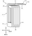
- FIG. 2Ais a perspective view of the coil as seen from the first turn side.
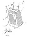
- FIG. 2Bis a perspective view of the coil as seen from the nth turn side.
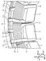
- FIG. 3Ais a top view of the main part of the stator.
- FIG. 3Bis a view of the main part of the stator as viewed from the inside in the radial direction.
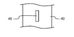
- FIG. 3Cis an enlarged view of a main part of the plate material.
- FIG. 3Dis an enlarged view of another main part of the plate material.
- FIG. 3Eis an enlarged view of still another main part of the plate material.
- the coil 40has a first lead portion 41, a second lead portion 42, and a winding portion 43.
- the coil 40is a molded coil formed by molding a conducting wire made of copper or the like having a quadrangular cross section.
- An insulating coating(not shown) is provided on the surface of the conducting wire constituting the coil 40.
- an insulating membersuch as an insulator or insulating paper is provided between the teeth 10 and the coil 40 shown in FIGS. 3A and 3B.
- the "molded coil" in the present specificationdoes not include a coil in which a conducting wire having a constant width and thickness is simply wound in a spiral shape.
- the forming coilis formed, for example, by preparing a plurality of rectangular plates having different lengths, widths or thicknesses, pressing these plates, and joining them by cold pressure welding, welding, or other methods.
- the material of the plate materialis a low resistance material such as copper or aluminum.
- a plate material having a different shapecan be prepared by performing the following processing. For example, as shown in FIG. 3C or FIG. 3D, a slit 46 or a hole 47 is formed in the plate material. Alternatively, as shown in FIG. 3E, a notch 48 is formed in the plate material.
- the molding coilmay be formed by so-called casting in which copper or the like is melted and poured into a mold.
- a molded coilmay be formed by bending a plate-shaped conducting wire having a width and a thickness different in the middle at a predetermined position.
- a plate-shaped conductor having a constant width and thicknessmay be rolled at a predetermined portion, the width and thickness may be changed in the middle, and then spirally wound to form a forming coil.
- the forming coilis formed by adding another process other than winding the conductor, or by a method different from simply winding the conductor.
- the winding portion 43has first to nth turns 431 to 43n in which the conducting wire is spirally wound.
- nis an integer of 2 or more.
- the first to nth turns 431 to 43nare stacked in this order from the center side to the outer peripheral side of the motor 1000, and are housed in the slot 30.
- Each shape of the first to nth turns 431 to 43nis a square ring having four sides when viewed from the radial direction.
- the winding portion 43has a first coil end 44 and a second coil end 45.
- the first coil end 44corresponds to the upper end side portion in the axial direction among the four side portions of the first to nth turns 431 to 43n.
- the second coil end 45corresponds to the lower end side portion in the axial direction among the four side portions of the first to nth turns 431 to 43n.
- the first lead portion 41is continuous with the end portion of the first turn 431.
- the first reed portion 41is bent at the end of the first turn 431 and extends along the upper surface of the first coil end 44 to the nth turn 43n. Further, it is bent upward in the vicinity of the nth turn 43n.
- the second lead portion 42is continuous with the nth turn 43n, is bent in the middle of the nth turn 43n, and extends above the first coil end 44.
- the end portion 41a of the first lead portion 41(hereinafter, simply referred to as the end portion 41a) and the end portion 42a of the second lead portion 42 (hereinafter, simply referred to as the end portion 42a).
- the predetermined distanceis shorter than the circumferential length of the portion of the first coil end 44 corresponding to the nth turn 43n.
- the end portion 41a and the end portion 42aare arranged at positions equidistant from the center of the motor 1000 when viewed from the axial direction. Specifically, when viewed from above, the end portions 41a and the end portions 42a are arranged on the same circumference centered on the axis of the yoke 20 corresponding to the center of the motor 1000. In other words, when viewed from the axial direction, the end portion 41a and the end portion 42a are arranged so that the outermost circumference of the first coil end 44, that is, the radial distance from the nth turn 43n is the same. There is.
- the end portion 41a and the end portion 42aare arranged so that the heights from the upper surface of the first coil end 44 are the same when viewed from the radial direction. Specifically, the length extending upward in the axial direction from the upper surface of the first coil end 44 is the same for the first lead portion 41 and the second lead portion 42.
- the first lead portion 41 and the second lead portion 42have the same shape in the portion extending from the nth turn 43n. Specifically, the width of the first lead portion 41 and the width of the second lead portion 42 are the same. The thickness of the first lead portion 41 and the thickness of the second lead portion 42 are the same.
- the width of the slot 30 in the circumferential directionis wider on the side closer to the yoke 20 than on the side closer to the rotor 200.
- the width of the nth turn 43n in the winding portion 43 of the coil 40becomes wider than the width of the first turn 431.
- the first lead portion 41is formed so as to have the same width as the first turn 431.
- the second lead portion 42is formed so as to have the same width as the first lead portion 41 so that the width is narrower than that of the nth turn 43n.
- the plurality of coils 40are arranged at equal intervals along the inner circumference of the yoke 20 according to the arrangement of the plurality of teeth 10.
- the first lead portions 41 provided on the plurality of coils 40are arranged at equal intervals along the circumferential direction.
- the second lead portions 42 provided on the plurality of coils 40are arranged at equal intervals along the circumferential direction. The distance between the first lead portion 41 and the second lead portion 42 along the circumferential direction in each coil 40 is the same.
- the end portion 41a provided on each of the plurality of coils 40 and the end portion 42a provided on each of the plurality of coils 40are located at the same height.
- each of the plurality of end portions 41a and end portion 42ais located at the same height with respect to the upper surface of the first coil end 44.
- the first lead portion 41 and the second lead portion 42 provided in the one coil 40each function as a connection portion with another coil 40. Alternatively, it functions as a connection portion between the bus bars 61 to 63 (see FIG. 3B) and the wiring.
- bus bars 61 to 63are connected to the first lead portion 41 and the second lead portion 42 provided in the respective coils 40 (FIG. 6). 3B) or the wiring is welded respectively. Therefore, the insulating film is removed from the portion of the first lead portion 41 including the end portion 41a. Similarly, the insulating coating is removed from the portion of the second lead portion 42 including the end portion 42a.
- the winding portion 43functions as a magnetic field generating portion when a current flows.
- the coil 40 according to the present embodimentis mounted on the motor 1000.
- the coil 40has a first lead portion 41, a second lead portion 42, and a winding portion 43.
- the winding portion 43is composed of first to nth (n is an integer of 2 or more) turns 431 to 43n laminated in this order from the center side to the outer peripheral side of the motor 1000 when viewed from the radial direction.
- the winding portion 43has a first coil end 44 located on the upper side in the axial direction and a second coil end 45 located on the lower side in the axial direction.
- the first lead portion 41extends from the first turn 431.
- the second lead portion 42extends from the nth turn 43n.
- the first lead portion 41is bent along the upper surface of the first coil end 44 so as to extend to the nth turn 43n.
- the end portion 41a and the end portion 42ahave the same height from the upper surface of the first coil end 44 when viewed from the radial direction, and are the outermost circumference of the first coil end 44 when viewed from the axial direction, that is, the first coil end 44.
- the distance from n-turn 43nis the same.
- the coil 40is the above-mentioned molded coil formed by molding a conducting wire.
- the coil 40By configuring the coil 40 in this way, it is possible to easily connect the plurality of coils 40.
- the end portion 41a and the end portion 42aare at the same position when viewed from the radial direction and the axial direction, when connecting between a plurality of coils 40 by welding or the like, There is no need to move jigs and the like in a complicated manner. In addition, there is no need to manually route the conductor to the welding position. As a result, the equipment for connection and the assembly process of the motor 1000 can be standardized, and the assembly cost of the motor 1000 can be reduced.
- the degree of freedom in shape designcan be increased.
- the first reed portion 41 and the second reed portion 42, and thus the end portion 41a and the end portion 42acan be arranged at appropriate positions according to the shapes of the stator 100 and the motor 1000, and between the coils 40. Can be easily connected.
- the second lead portion 42extends upward along the axial direction, and the end portion 42a is located above the first coil end 44.
- the first lead portion 41is further bent upward in the vicinity of the nth turn 43n.
- the first lead portion 41 and the second lead portion 42which are connection portions, can be arranged above the coil 40. Further, when connecting the coils 40, the jig, the welding head, and the like can be easily moved. As a result, the connection between the coils 40 can be easily performed.
- first lead portion 41 and the second lead portion 42have the same shape in the portion extending from the nth turn 43n.
- the thickness of the first reed portion 41is the same as the thickness of the second reed portion 42 in the portion extending from the nth turn 43n.
- the width of the first lead portion 41in this case, the width in the circumferential direction is preferably the same as the width of the second lead portion 42.
- the stator 100has at least an annular yoke 20, a plurality of teeth 10 connected to the inner circumference of the yoke 20, and a plurality of coils 40 wound around each of the plurality of teeth 10.
- the first lead portions 41 provided in each of the plurality of coils 40are arranged at equal intervals along the circumferential direction.
- the second lead portions 42 provided in each of the plurality of coils 40are arranged at equal intervals along the circumferential direction.
- the end portion 41ais located at the same height as the end portion 42a.
- the end portion 41a and the end portion 42aare located on the same circumference centered on the axial center of the yoke 20.
- the reference position of the heights of the ends 41a and 42ais the axial upper end surface of the insulator 50 or the insulating paper (not shown) mounted on the teeth 10. As described above, the axis of the yoke 20 corresponds to the center of the motor 1000.
- stator 100By configuring the stator 100 in this way, the positions of the first lead portion 41 and the second lead portion 42 in the stator 100 are regularly fixed. This makes it possible to easily connect between different coils 40 or between the coils 40 and the bus bars 61 to 63. In addition, the connection process can be standardized.
- stator 100is rotatably held with respect to the axis of the yoke 20
- stator 100is rotated at equal intervals, in this case, at each arrangement pitch of the coils 40, and between different coils 40 or between the coils 40 and the bus bar 61.
- Welding work with 63is performed. As a result, the welding work can be greatly simplified.
- the positions of the first lead portion 41 and the second lead portion 42 in the stator 100are regularly fixed, it is possible to easily mask a portion other than the connection portion during the connection work.
- a portion other than the connection portionFor example, in the welding work between the first reed portion 41 or the second reed portion 42 and the bus bars 61 to 63, by covering the parts other than the welded portion with a cover or the like (not shown), spatter or the like generated during welding is scattered around. , It is possible to prevent the insulating coating of the coil 40 from being damaged. It is possible to prevent an unintended short circuit between the coils 40, the coil 40 and the teeth 10, or the yoke 20 and suppress an initial failure of the stator 100. As a result, the assembly cost of the stator 100 can be reduced. Moreover, the quality of the stator 100 can be maintained.
- the connection work between the adjacent coils 40can be easily performed.
- welding between adjacent coils 40can be easily performed. Therefore, the assembly work of the stator 100 can be simplified.
- the motor 1000includes at least a rotor 200 having an output shaft 210 as an axis, and a stator 100 provided coaxially with the rotor 200 and at a predetermined distance from the rotor 200.
- connection work between the coils 40 or between the coils 40 and the bus bars 61 to 63 and the likecan be easily performed, and the connection process can be standardized.
- the assembly cost of the stator 100 and, by extension, the motor 1000can be reduced.
- the quality of the motor 1000can be maintained.
- the coil 40 of the present embodimentis a coil 40 mounted on the motor 1000 in which the rotor 200 rotates about the axis of rotation, and the motor 1000 is viewed from the radial direction of the motor 1000 orthogonal to the axis.
- a winding portion 43composed of first to nth (n is an integer of 2 or more) turns laminated in this order from the center side to the outer peripheral side, and a first lead portion 41 extending from the first turn.
- a second lead portion 42 extending from the nth turnis provided.
- the winding portion 43has a first coil end 44 located on one side in the axial direction in which the axial line extends, and a second coil end 45 located on the other side in the axial direction.
- the first lead portion 41is bent so as to extend to the nth turn along a surface located on one side of the first coil end 44, and the end portions 41a and the second lead portion 41 of the first lead portion 41
- the end portion 42a of the lead portion 42has the same height from the surface located on one side of the first coil end 44 when viewed from the radial direction, and the distance from the nth turn when viewed from the axial direction is the same. It is the same.
- connection processcan be standardized.
- the second lead portion 42extends to one side along the axial direction, and its end portion is located on one side of the first coil end 44, and the first lead portion 41 is nth. It is preferable that it is further bent to one side in the vicinity of the turn.
- the second lead portion 42is bent toward the outer peripheral side of the motor 1000 in the vicinity of the surface located on one side of the first coil end 44.
- the thickness of the first lead portion 41is the same as the thickness of the second lead portion 42, and the width of the first lead portion 41 is the same as the width of the second lead portion 42. ..
- the stator 100 of the present embodimentincludes an annular yoke 20, a plurality of teeth 10 connected to the inner circumference of the yoke 20, and a plurality of coils 40 wound around each of the plurality of teeth 10.
- Each of the plurality of coils 40is the coil 40 of the present embodiment described above, and the first lead portion 41 provided in each of the plurality of coils 40 extends in the circumferential direction of the motor 1000 and the like.
- the second lead portions 42 arranged at intervals and provided in each of the plurality of coils 40are arranged at equal intervals along the circumferential direction, and are arranged at equal intervals along the circumferential direction, and the end portion 41a of the first lead portion 41 is arranged when viewed from the radial direction.
- the end portion 41a of the first lead portion 41 and the end portion 42a of the second lead portion 42are It is located on the same circumference centered on the axis of the yoke 20.
- connection processcan be standardized.
- first lead portion 41 and the second lead portion 42are arranged at equal intervals with each other.
- the motor 1000 of the present embodimentincludes a rotor 200 having an output shaft 210 as an axis, and a stator 100 of the present embodiment provided coaxially with the rotor 200 and at a predetermined distance from the rotor 200. , At least.
- FIG. 4is a perspective view of the coil according to the first modification.
- FIG. 5is a perspective view of another coil according to the first modification.
- the same reference numeralsare given to the same parts as those in the embodiment, and detailed description thereof will be omitted.
- the second lead portion 42is bent in the middle of the nth turn 43n and extends outward in the radial direction.
- the first reed portion 41is bent at the end of the first turn 431 and extends along the upper surface of the first coil end 44 to the radial outside of the nth turn 43n.
- Both the first lead portion 41 and the second lead portion 42extend along the radial direction, and the end portion 41a and the end portion 42a are on the same circumference centered on the axis of the yoke 20. It is in. In this case, the end portion 41a and the end portion 42a are at the same position on the radial outer side of the coil 40. As shown in FIG. 4, the end portion 41a and the end portion 42a are at substantially the same height when viewed from the axial direction. In this case, the end portion 41a and the end portion 42a are located at the same position closer to the upper surface of the first coil end 44 than in the configuration shown in the embodiment.
- the height of the end portion 41a and the end portion 42acan be made lower than the configuration shown in the embodiment when viewed from the radial direction. As a result, the height of the coil 40 including the connection portion can be reduced.
- the end portion 41a and the end portion 42aBy arranging the end portion 41a and the end portion 42a radially outside the nth turn 43n of the coil 40, a space can be secured above the first coil end 44. This allows wiring and busbars (not shown) to be placed above the first coil end 44. Therefore, the coil 40 including the wiring and the bus bar can be reduced in height and size.
- this modificationis used.
- the configuration shownis effective in reducing the height and size of the coil 40.
- the first lead portion 41 extending radially outward from the nth turn 43nmay be bent downward in the middle.
- a plurality of first reed portions 41 extending radially outward of the nth turn 43nmay be further bent along the upper surface of the first coil end 44. That is, when viewed from the axial direction, the first lead portion 41 and the second lead portion 42 are bent downward, then extend outward in the radial direction, and are further bent upward in the axial direction.
- the end portion 41ais located at the same height as the upper surface of the first coil end 44 when viewed from the radial direction.
- the end portion 42ais located at the same height as the end portion 41a when viewed from the radial direction.
- the height of the end portion 41a and the end portion 42acan be made even lower than the configuration shown in the modification 1 when viewed from the radial direction. Therefore, the height can be suppressed for welding in the axial direction. As a result, the height of the coil 40 including the connection portion can be reduced.
- the end portion 41a and the end portion 42aBy arranging the end portion 41a and the end portion 42a radially outside the nth turn 43n of the coil 40, a space can be secured above the first coil end 44. As a result, wiring and a bus bar (not shown) can be arranged above the first coil end 44. Therefore, the coil 40 including the wiring and the bus bar can be reduced in height and size.
- this modificationis used.
- the configuration shownis effective in reducing the height and size of the coil 40.
- the end portion 41amay be located flush with or below the upper surface of the first coil end 44 when viewed from the radial direction.
- the second lead portion 42is bent downward from the end portion of the nth turn 43n and extends outward in the radial direction. You may do so.
- the first reed portion 41may extend to the outside of the nth turn when viewed from the radial direction, and may be bent a plurality of times outside the nth turn.
- FIG. 6Ais a perspective view of the coil according to the second modification.
- FIG. 6Bis a schematic cross-sectional view taken along the line VIB-VIB of FIG. 6A.
- the configuration shown in this modificationdiffers from the configuration shown in the embodiment in the following points.
- the corners 44a of the first coil ends 44 facing each otherare chamfered.
- the first reed portion 41extends through the corner portions 44a of the first coil end 44 to the nth turn 43n and is bent upward in the vicinity of the nth turn 43n.
- the height of the end portion 41acan be made even lower than the configuration shown in the embodiment when viewed from the radial direction. As a result, the height of the coil 40 including the connection portion can be reduced.
- the wiring and the bus barcan be arranged above the first coil end 44, and the coil 40 including the wiring and the bus bar can be reduced in height and size.
- the corner portion 44a of the first coil end 44has a larger cross-sectional area than the other portions of the first to nth turns 431 to 43n. Therefore, even if the corner portion 44a is chamfered.
- the resistance of the coil 40hardly increases, and it is possible to suppress an increase in loss when a current flows through the coil 40.
- the corner portion 44a of the first coil end 44may have a linear chamfered shape as shown in FIG. 6A. However, the corner portion 44a of the first coil end 44 may have, for example, an R chamfered shape. In the latter case, since the corner portion 44a has a rounded shape, for example, damage to the insulating coating of the first lead portion 41 can be suppressed. Further, the stress concentration on the corner portion 44a can be relaxed.
- stator 100is configured by mounting the plurality of coils 40 shown in the present modification on the plurality of teeth 10 shown in FIG.
- the coil 40is reduced in height and size. Therefore, the stator 100 itself can be miniaturized in the axial direction.
- the corner portion 44a of the first coil end 44has an R chamfered shape, damage to the insulating coating of the first lead portion 41 can be suppressed. Therefore, the leakage current from the coil 40 to the teeth 10 or the yoke 20 can be suppressed. As a result, it is possible to suppress a decrease in the strength of the rotating magnetic field generated in the stator 100.
- the corners 44a of the first coil ends 44 facing each otherare chamfered, and the first coil ends 44 facing each other have a chamfered shape.
- a first lead portion 41may be accommodated between the corner portions 44a and extends to the nth turn or its radial outer side.
- FIG. 7is a perspective view of the coil according to the modified example 3.
- the configuration shown in this modificationdiffers from the configuration shown in the embodiment in the following points.
- the first lead portion 41is bent on the upper surface of the first coil end 44 in the circumferential direction and the radial direction, respectively, and is located diagonally to the end portion of the first turn 431 when viewed from the axial direction. ..
- the second lead portion 42is arranged at a predetermined distance from the first lead portion 41 in the circumferential direction when viewed from the axial direction.
- the positions of the end portion 41a and the end portion 42a in the coil 40can be exchanged as compared with the coil 40 shown in the embodiment.
- Thismakes it possible to increase the degree of freedom regarding the connection between the coils 40 in the stator 100. For example, when it is desired to connect the first lead portions 41 to each other between adjacent coils 40, the two first lead portions 41 can be brought close to each other. Therefore, the connection work becomes easy. Further, it is possible to increase the degree of freedom in routing the wiring and the bus bar connecting the coils 40. Therefore, the design cost of the motor 1000 can be reduced.
- the first lead portion 41is a surface located on one side of the first coil end 44, and is bent in the circumferential direction and the radial direction around the axis, respectively.
- the second lead portion 42is located diagonally to the end of the first turn when viewed from the axial direction, and the second lead portion 42 is spaced apart from the first lead portion 41 in the circumferential direction when viewed from the axial direction. May be arranged apart from each other.
- FIG. 8is a schematic view of the winding portion of the coil according to the modified example 4 as viewed from the radial direction.
- the first lead portion 41 and the second lead portion 42are not shown.
- the configuration shown in this modificationis the embodiment in that the height of the first coil end 44, in this case, the height A in the axial direction is lower than the height B of the second coil end 45. It is different from the configuration shown.
- the coil 40particularly the winding portion 43 in this way, the height of the end portion 41a and the end portion 42a with respect to the upper surface of the first coil end 44 is not changed, and the first lead portion 41 And the axial length of the second lead portion 42 can be made longer than the configuration shown in the embodiment.
- the coil 40By configuring the coil 40, particularly the winding portion 43 in this way, the axial lengths of the first lead portion 41 and the second lead portion 42 with respect to the upper surface of the first coil end 44 can be changed. If not, the positions of the end 41a and the end 42a can be lower than in the configuration shown in the embodiment. As a result, the height and size of the coil 40 can be reduced.
- the axial height of the first coil end 44may be lower than the axial height of the second coil end 45 ”.
- each component shown in the above-mentioned modification and embodimentcan be appropriately combined to form a new embodiment.
- the winding portion 43 shown in the modified example 4may be applied to the embodiment or the configuration shown in the modified examples 1 to 3.
- the cross-sectional shape of the conducting wire constituting the coil 40is not particularly limited to a quadrangle, and may be another shape. For example, it may be an m-square (m is an integer of 3 or more).
- wiring or connection with the bus barmay be performed below the coil 40.
- the first reed portion 41is bent along the lower surface of the second coil end 45 so as to extend to the nth turn 43n.
- the end portion 41a and the end portion 42ahave the same height from the upper surface of the first coil end 44 when viewed from the radial direction, and the distance from the nth turn 43n when viewed from the axial direction. Will be the same. By doing so, it is possible to obtain the same effect as that of the configuration shown in the embodiment.
- the coil of the present inventioncan be easily connected between coils or with a bus bar, and is useful for application to a motor.
Landscapes
- Engineering & Computer Science (AREA)
- Power Engineering (AREA)
- Insulation, Fastening Of Motor, Generator Windings (AREA)
- Windings For Motors And Generators (AREA)
Abstract
Description
Translated fromJapanese本発明は、コイル、特に成形コイル、及びそれを備えたステータ及びモータに関する。The present invention relates to a coil, particularly a molded coil, and a stator and a motor provided with the coil.
近年、産業、車載用途でモータの需要は高まっている。その中で、モータの効率向上、低コスト化が要望されている。In recent years, the demand for motors has been increasing for industrial and in-vehicle applications. Among them, improvement of motor efficiency and cost reduction are required.
モータの効率向上手法の一つとして、ステータのスロット内に配置されるコイルの占積率を向上させることが知られている。コイルの占積率を向上させることで、モータの駆動時に、コイルに流れる電流に起因する損失を抑制できる。It is known to improve the space factor of the coil arranged in the slot of the stator as one of the methods for improving the efficiency of the motor. By improving the space factor of the coil, it is possible to suppress the loss caused by the current flowing through the coil when the motor is driven.
コイルの占積率を向上させる手法として、銅材を用いた鋳造コイルをスロット内に配置する構成が提案されている(例えば特許文献1を参照)。As a method for improving the space factor of the coil, a configuration in which a cast coil using a copper material is arranged in a slot has been proposed (see, for example, Patent Document 1).
ところで、一般的なエッジワイズコイル、及び、特許文献1に開示されたコイルでは、コイルの巻き始め部分と巻き終わり部分との位置が、モータの半径方向でそれぞれ異なっていた。このため、巻き始め部分から延びるリード部と巻き終わり部分から延びるリード部とが、モータの中心から等距離の位置にない、言い換えると同じ円周上に位置していなかった。By the way, in the general edgewise coil and the coil disclosed in Patent Document 1, the positions of the winding start portion and the winding end portion of the coil are different in the radial direction of the motor. Therefore, the lead portion extending from the winding start portion and the lead portion extending from the winding end portion are not located at equal distances from the center of the motor, in other words, they are not located on the same circumference.
しかし、このような場合、異なるコイル間を直接、あるいはバスバー等を介して接続する際に、治具及び接続用設備を頻繁に動かす必要があった。したがって、接続作業が煩雑になっていた。特に、接続工法として溶接工法を用いる場合、間隔が狭いリード部の間で溶接ヘッドを頻繁に動かして溶接位置に正確に移動させることは難しかった。コイルまたはステータ自体を移動させようとすると、そのための設備が大型化、複雑化していた。このため、モータの組立コストが増加してしまうおそれがあった。However, in such a case, it is necessary to frequently move the jig and the connecting equipment when connecting different coils directly or via a bus bar or the like. Therefore, the connection work has become complicated. In particular, when the welding method is used as the connection method, it is difficult to frequently move the welding head between the lead portions having a narrow interval to accurately move the welding head to the welding position. When trying to move the coil or the stator itself, the equipment for that purpose has become large and complicated. Therefore, there is a risk that the assembly cost of the motor will increase.
本発明はかかる点に鑑みてなされたものである。本発明の目的は、他の部材との接続作業を簡便に行うことのできるコイル及びそれを備えたステータ及びモータを提供することにある。The present invention has been made in view of this point. An object of the present invention is to provide a coil capable of easily performing connection work with other members, and a stator and a motor provided with the coil.
上記の目的を達成するために、本発明に係るコイルは、軸線を回転中心としてロータが回転するモータに装着されるコイルであって、前記軸線と直交する前記モータの半径方向から見て、前記モータの中心側から外周側に向けてこの順で積層された第1~第n(nは2以上の整数)ターンからなる巻線部と、前記第1ターンから延びる第1のリード部と、前記第nターンから延びる第2のリード部と、を備え、前記巻線部は、前記軸線が延伸する方向である軸方向の一方側に位置する第1のコイルエンドと、前記軸方向の他方側に位置する第2のコイルエンドとを有しており、前記第1のリード部は、前記第1のコイルエンドの前記一方側に位置する面に沿って前記第nターンまで延びるように折り曲げられており、前記第1のリード部の端部と前記第2のリード部の端部とは、前記径方向から見て前記第1のコイルエンドの前記一方側に位置する面からの高さが同じであるとともに、前記軸方向から見て前記第nターンからの距離が同じである。In order to achieve the above object, the coil according to the present invention is a coil mounted on a motor in which the rotor rotates with the axis of rotation as the center of rotation, and is described as described above when viewed from the radial direction of the motor orthogonal to the axis. A winding portion composed of first to nth (n is an integer of 2 or more) turns laminated in this order from the center side to the outer peripheral side of the motor, and a first lead portion extending from the first turn. A second lead portion extending from the nth turn is provided, and the winding portion includes a first coil end located on one side in the axial direction in which the axial line extends, and the other in the axial direction. It has a second coil end located on the side, and the first lead portion is bent so as to extend to the nth turn along a surface of the first coil end located on the one side. The height of the end of the first lead portion and the end of the second lead portion from a surface of the first coil end located on one side of the first coil end when viewed from the radial direction. Are the same, and the distance from the nth turn when viewed from the axial direction is the same.
本発明に係るステータは、環状のヨークと、前記ヨークの内周に接続された複数のティースと、前記複数のティースのそれぞれに巻回された複数のコイルと、を有し、前記複数のコイルの各々は、上記の本発明に係るコイルであり、前記複数のコイルのそれぞれに設けられた前記第1のリード部は、前記モータの周方向に亘って等間隔に配置され、前記複数のコイルのそれぞれに設けられた前記第2のリード部は、周方向に沿って等間隔に配置され、前記半径方向から見て、前記第1のリード部の端部は、前記第2のリード部の端部と同じ高さに位置し、前記軸方向から見て、前記第1のリード部の端部と前記第2のリード部の端部とは、前記ヨークの軸心を中心とする同じ円周上に位置している。The stator according to the present invention has an annular yoke, a plurality of teeth connected to the inner circumference of the yoke, and a plurality of coils wound around each of the plurality of teeth, and the plurality of coils. Each of the above-described coils according to the present invention, and the first lead portions provided in each of the plurality of coils are arranged at equal intervals in the circumferential direction of the motor, and the plurality of coils are arranged at equal intervals. The second lead portions provided in each of the above are arranged at equal intervals along the circumferential direction, and the end portion of the first lead portion is the end portion of the second lead portion when viewed from the radial direction. Located at the same height as the end portion, when viewed from the axial direction, the end portion of the first lead portion and the end portion of the second lead portion are the same circle centered on the axial center of the yoke. It is located on the circumference.
本発明に係るモータは、出力軸を軸心に有するロータと、前記ロータと同軸にかつ前記ロータと所定の間隔をあけて設けられた前記ステータと、を少なくとも備える。The motor according to the present invention includes at least a rotor having an output shaft as an axis and a stator provided coaxially with the rotor and at a predetermined distance from the rotor.
本発明のコイルによれば、コイル間及びコイルとバスバー等とを簡便に接続できる。また、接続工程を標準化できる。本発明のステータによれば、隣接する、あるいは離間したコイル間を簡便に接続できる。また、接続工程を標準化できる。本発明のモータによれば、ステータの組立工程を標準化できる。また、組立コストを低減できる。According to the coil of the present invention, it is possible to easily connect between the coils and between the coil and the bus bar or the like. In addition, the connection process can be standardized. According to the stator of the present invention, adjacent or separated coils can be easily connected. In addition, the connection process can be standardized. According to the motor of the present invention, the assembly process of the stator can be standardized. Moreover, the assembly cost can be reduced.
以下、本発明の実施形態を図面に基づいて詳細に説明する。以下の好ましい実施形態の説明は、本質的に例示に過ぎず、本発明、その適用物或いはその用途を制限することを意図するものでは全くない。Hereinafter, embodiments of the present invention will be described in detail with reference to the drawings. The following description of preferred embodiments is merely exemplary and is not intended to limit the present invention, its applications or its uses.
(実施形態)
[モータの構成]
図1は、本発明の実施形態に係るモータ1000の模式図である。なお、以降の説明において、モータ1000の半径方向を「径方向」と、外周方向を「周方向」と、モータ1000の出力軸210の軸線方向(図1における紙面と垂直な方向)を「軸方向」とそれぞれ呼ぶことがある。径方向において、モータ1000の軸心側を径方向内側と、外周側を径方向外側と呼ぶことがある。図1において、後で述べるコイル40の第1のリード部41と、第2のリード部42については、図示を省略している。なお、軸方向から見て、モータ1000の軸心は、出力軸210の軸線に一致する。(Embodiment)
[Motor configuration]
FIG. 1 is a schematic view of a
モータ1000は、ステータ100とロータ200とを有している。なお、モータ1000は、これら以外の構成部品、例えば、モータケース及び出力軸を軸支する軸受等の部品を有しているが、説明の便宜上、その図示及び説明を省略する。The
ステータ100は、円環状のヨーク20と、複数のティース10と、スロット30と、コイル40とを有している。複数のティース10は、ヨーク20の内周に接続され、当該内周に沿って等間隔に設けられている。スロット30は、周方向に隣り合うティース10の間にそれぞれ設けられている。コイル40は、スロット30内に収容されている。ステータ100は、ロータ200の径方向外側に、ロータ200と一定の間隔をあけて配置されている。The
ティース10とヨーク20は、それぞれ、例えば、ケイ素等を含有した電磁鋼板を積層後に打ち抜き加工して形成される。コイル40は、インシュレータ50(図3Bを参照)を挟んで複数のティース10のそれぞれに装着されて、スロット30内に収容されている。なお、コイル40の形状については、後で詳述する。The
コイル40に流れる電流の位相に応じて、コイルをコイルU1~U4,V1~V4,W1~W4とそれぞれ呼ぶことがある。The coils may be referred to as coils U1 to U4, V1 to V4, W1 to W4, respectively, depending on the phase of the current flowing through the
ロータ200は、出力軸210と、出力軸210を軸心に有するロータコア220と、ロータコア220の内部に埋設され、ステータ100に対向してN極、S極が出力軸の外周方向に沿って交互に配置された複数の磁石230とを有している。磁石230の材料、形状、及び材質については、モータ1000の出力等に応じて適宜変更しうる。ロータコア220は、例えば、ケイ素等を含有した電磁鋼板を積層後に打ち抜き加工して形成される。The
コイルU1~U4,V1~V4,W1~W4はそれぞれ直列に接続されている。互いに電気角で120°の位相差を有するU,V,W相の3相の電流がそれぞれコイルU1~U4,V1~V4,W1~W4に供給されて励磁され、ステータ100に回転磁界が発生する。この回転磁界と、ロータ200に設けられた磁石230が発生する磁界との間で相互作用を生じてトルクが発生し、出力軸210が図示しない軸受に支持されて回転する。Coil U1 to U4, V1 to V4, W1 to W4 are connected in series, respectively. Three phases of U, V, and W, which have a phase difference of 120 ° in electrical angle from each other, are supplied to and excited by the coils U1 to U4, V1 to V4, and W1 to W4, respectively, and a rotating magnetic field is generated in the
[コイル及びステータの要部の構成]
図2Aは、第1ターン側から見たコイルの斜視図である。図2Bは、第nターン側から見たコイルの斜視図である。図3Aは、ステータの要部を上から見た図である。図3Bは、ステータの要部を径方向内側から見た図である。また、図3Cは、板材の要部拡大図である。図3Dは、板材の他の要部拡大図である。図3Eは、板材のさらに他の要部拡大図である。[Structure of main parts of coil and stator]
FIG. 2A is a perspective view of the coil as seen from the first turn side. FIG. 2B is a perspective view of the coil as seen from the nth turn side. FIG. 3A is a top view of the main part of the stator. FIG. 3B is a view of the main part of the stator as viewed from the inside in the radial direction. Further, FIG. 3C is an enlarged view of a main part of the plate material. FIG. 3D is an enlarged view of another main part of the plate material. FIG. 3E is an enlarged view of still another main part of the plate material.
図2A、図2Bに示すように、コイル40は、第1のリード部41と第2のリード部42と巻線部43とを有している。コイル40は、断面が四角形の銅等からなる導線が成形されてなる成形コイルである。コイル40を構成する導線の表面には、図示しない絶縁被膜が設けられている。同様に、図3A、図3Bに示すティース10とコイル40との間には、図示しない、インシュレータあるいは絶縁紙などの絶縁部材が設けられている。As shown in FIGS. 2A and 2B, the
なお、本願明細書における「成形コイル」は、幅及び厚さが一定の導線が螺旋状に巻回されただけのコイルを含まない。Note that the "molded coil" in the present specification does not include a coil in which a conducting wire having a constant width and thickness is simply wound in a spiral shape.
成形コイルは、例えば、長さ、幅あるいは厚みが異なる複数の長方形の板材を準備し、これらの板材をプレスすること、及び、冷間圧接、溶接、またはその他の方法で接合することで形成される。板材の材質は、銅またはアルミニウム等の低抵抗材料である。板材は、つぎのような加工を施すことにより、一部の形状が異なるものを準備することができる。例えば、図3Cまたは図3Dに示すように、板材には、スリット46または穴47が形成される。あるいは、図3Eに示すように、板材には、切欠き48が形成される。The forming coil is formed, for example, by preparing a plurality of rectangular plates having different lengths, widths or thicknesses, pressing these plates, and joining them by cold pressure welding, welding, or other methods. To. The material of the plate material is a low resistance material such as copper or aluminum. A plate material having a different shape can be prepared by performing the following processing. For example, as shown in FIG. 3C or FIG. 3D, a
あるいは、成形コイルは、銅等を溶融して鋳型に流し込む、いわゆる鋳造により形成されてもよい。幅や厚さを予め途中で異なるように形成した板状の導線を所定の位置で曲げ加工することで、成形コイルが形成されてもよい。あるいは、幅及び厚さが一定の板状の導線を所定の部位で圧延加工して、途中で幅及び厚さを変更した後に螺旋状に巻回して、成形コイルが形成されてもよい。要するに、導線を巻回する以外にさらに別の加工を加えるか、あるいは、単に巻き回すのとは異なる工法で成形コイルは形成される。Alternatively, the molding coil may be formed by so-called casting in which copper or the like is melted and poured into a mold. A molded coil may be formed by bending a plate-shaped conducting wire having a width and a thickness different in the middle at a predetermined position. Alternatively, a plate-shaped conductor having a constant width and thickness may be rolled at a predetermined portion, the width and thickness may be changed in the middle, and then spirally wound to form a forming coil. In short, the forming coil is formed by adding another process other than winding the conductor, or by a method different from simply winding the conductor.
巻線部43は、導線が螺旋状に巻回されてなる第1~第nターン431~43nを有している。ここで、nは2以上の整数である。第1~第nターン431~43nは、モータ1000の中心側から外周側に向けてこの順で積層されて、スロット30内に収容される。第1~第nターン431~43nの各々の形状は、径方向から見て4つの辺部を有する四角環状である。The winding
巻線部43は、第1のコイルエンド44と第2のコイルエンド45とを有している。第1のコイルエンド44は、第1~第nターン431~43nの4つの辺部のうち軸方向の上端辺部に相当する。また、第2のコイルエンド45は、第1~第nターン431~43nの4つの辺部のうち軸方向の下端辺部に相当する。The winding
第1のリード部41は、第1ターン431の端部に連続している。第1のリード部41は、第1ターン431の端部で折り曲げられて、第1のコイルエンド44の上面に沿って、第nターン43nまで延びている。また、第nターン43nの近傍で上方に折り曲げられている。The
第2のリード部42は、第nターン43nに連続しており、第nターン43nの途中で折り曲げられて第1のコイルエンド44の上方に延びている。The
図2Aから図3Bに示すように、第1のリード部41の端部41a(以下、単に端部41aという)と、第2のリード部42の端部42a(以下、単に端部42aという)とは、周方向に沿って所定の距離をあけて配置されている。この場合、所定の距離は、第1のコイルエンド44のうち、第nターン43nに対応する部分の周方向の長さよりも短い。As shown in FIGS. 2A to 3B, the
一方、端部41aと端部42aとは、軸方向から見て、モータ1000の中心から等距離の位置に配置されている。具体的には、上から見て、モータ1000の中心に相当するヨーク20の軸心を中心とした同じ円周上に端部41aと端部42aとが配置されている。言い換えると、軸方向から見て、端部41aと端部42aとは、第1のコイルエンド44の最外周、つまり、第nターン43nからの径方向の距離が同じになるように配置されている。On the other hand, the
端部41aと端部42aとは、径方向から見て、第1のコイルエンド44の上面からの高さが同じになるように配置されている。具体的には、第1のコイルエンド44の上面から軸方向の上方に延びる長さが、第1のリード部41と第2のリード部42とで同じである。The
なお、本願明細書において、「同じ」、「等しい」、「同一」とは、モータ1000を構成する各部品の製造公差または組立公差を含む意であり、比較対象同士が厳密な意味で同じ、または等しい、あるいは同一であることまでを意味するものではない。In the specification of the present application, "same", "equal", and "same" mean to include manufacturing tolerances or assembly tolerances of each component constituting the
第nターン43nから延びた部分において、第1のリード部41と第2のリード部42とは、同じ形状である。具体的には、第1のリード部41の幅と第2のリード部42の幅とは同じである。第1のリード部41の厚さと第2のリード部42の厚さとは同じである。The
一般に、スロット30の周方向の幅は、ロータ200に近い側よりもヨーク20に近い側が広い。スロット30の形状に応じて、コイル40の巻線部43において、第nターン43nの幅は、第1ターン431の幅よりも広くなる。Generally, the width of the
第1のリード部41は、第1ターン431と幅が同じになるように形成されている。第2のリード部42は、第nターン43nよりも幅が狭くなるように、前述の通り、第1のリード部41と幅が同じになるように形成されている。The
また、図1及び図3A、図3Bに示すように、複数のコイル40は、複数のティース10の配置に応じて、ヨーク20の内周に沿って等間隔に配置されている。この配置関係に応じて、複数のコイル40にそれぞれ設けられた第1のリード部41は、周方向に沿って等間隔で配置される。同様に、複数のコイル40にそれぞれ設けられた第2のリード部42は、周方向に沿って等間隔で配置される。各コイル40内での周方向に沿った第1のリード部41と第2のリード部42との間隔は、いずれも同じである。Further, as shown in FIGS. 1 and 3A and 3B, the plurality of
径方向から見て、複数のコイル40にそれぞれ設けられた端部41aと、複数のコイル40にそれぞれ設けられた端部42aとは、同じ高さに位置している。例えば、複数の端部41a及び端部42aのそれぞれが、第1のコイルエンド44の上面を基準として同じ高さに位置している。When viewed from the radial direction, the
一のコイル40に設けられた第1のリード部41と第2のリード部42とは、それぞれ、他のコイル40との結線部として機能する。あるいは、バスバー61~63(図3Bを参照)及び配線との結線部として機能する。例えば、前述した同じU相のコイル40の間を溶接により接続する際に、それぞれのコイル40に設けられた第1のリード部41と第2のリード部42とに、バスバー61~63(図3Bを参照)または配線がそれぞれ溶接される。このため、第1のリード部41のうち端部41aを含む部分では、絶縁被膜が除去されている。同様に、第2のリード部42のうち端部42aを含む部分では、絶縁被膜が除去されている。一方、巻線部43は、電流が流れることで、磁界発生部として機能する。The
[効果等]
以上説明したように、本実施形態に係るコイル40は、モータ1000に装着される。コイル40は、第1のリード部41と第2のリード部42と巻線部43とを有している。[Effects, etc.]
As described above, the
巻線部43は、径方向から見て、モータ1000の中心側から外周側に向けてこの順で積層された第1~第n(nは2以上の整数)ターン431~43nからなる。巻線部43は、軸方向の上側に位置する第1のコイルエンド44と、軸方向の下側に位置する第2のコイルエンド45とを有している。The winding
第1のリード部41は、第1ターン431から延びている。第2のリード部42は、第nターン43nから延びている。The
第1のリード部41は、第1のコイルエンド44の上面に沿って、第nターン43nまで延びるように折り曲げられている。端部41aと端部42aとは、径方向から見て第1のコイルエンド44の上面からの高さが同じであるとともに、軸方向から見て第1のコイルエンド44の最外周、つまり第nターン43nからの距離が同じである。コイル40は、導線を成形してなる前述の成形コイルである。The
コイル40をこのように構成することで、複数のコイル40間の接続を容易に行うことができる。特に、端部41aと端部42aとが、径方向から見て、また、軸方向から見て、それぞれ同じ位置にあることで、溶接等により、複数のコイル40間の接続を行う際に、治具等を複雑に移動させる必要がない。また、手作業で溶接位置まで導線を引き回す必要がない。このことにより、接続用の設備及びモータ1000の組立工程を標準化でき、また、モータ1000の組立コストを低減できる。By configuring the
また、コイル40として成形コイルを用いることにより、その形状設計の自由度を高められる。このことにより、第1のリード部41及び第2のリード部42、ひいては、端部41a及び端部42aを、ステータ100やモータ1000の形状に応じて、適切な位置に配置でき、コイル40間の接続を簡便に行うことができる。Further, by using a molded coil as the
第2のリード部42は、軸方向に沿って上方に延びて、端部42aが第1のコイルエンド44の上方に位置している。第1のリード部41は、第nターン43nの近傍で上方にさらに折り曲げられている。The
コイル40をこのように構成することで、コイル40の上方に、結線部である第1のリード部41及び第2のリード部42を配置することができる。また、コイル40間の接続時に、治具や溶接ヘッド等の移動が容易となる。このことにより、コイル40間の接続を容易に行うことができる。By configuring the
第nターン43nから延びた部分において、第1のリード部41と第2のリード部42とは、同じ形状であることが好ましい。具体的には、第nターン43nから延びた部分において、第1のリード部41の厚さは、第2のリード部42の厚さと同じであることが好ましい。第1のリード部41の幅、この場合、周方向の幅は、第2のリード部42の幅と同じであることが好ましい。It is preferable that the
このようにすることで、バスバー61~63または配線との接続時に、第1のリード部41と第2のリード部42とで治具や設備配置等を変更する必要がなく、接続工程を標準化できる。また、溶接により、バスバー61~63または配線と第1のリード部41または第2のリード部42とを接続する際に、溶接条件を同じにでき、溶接工程の標準化が図れる。By doing so, when connecting to the bus bars 61 to 63 or the wiring, it is not necessary to change the jig, equipment arrangement, etc. between the
ステータ100は、環状のヨーク20と、ヨーク20の内周に接続された複数のティース10と、複数のティース10のそれぞれに巻回された複数のコイル40とを少なくとも有している。The
複数のコイル40のそれぞれに設けられた第1のリード部41は、周方向に沿って等間隔に配置されている。複数のコイル40のそれぞれに設けられた第2のリード部42は、周方向に沿って等間隔に配置されている。径方向から見て、端部41aは、端部42aと同じ高さに位置している。軸方向から見て、端部41aと端部42aとは、ヨーク20の軸心を中心とする同じ円周上に位置している。The
なお、端部41a,42aの高さの基準位置は、ティース10に装着されたインシュレータ50または絶縁紙(図示せず)の軸方向の上端面である。前述した通り、ヨーク20の軸心はモータ1000の中心に相当する。The reference position of the heights of the
ステータ100をこのように構成することで、ステータ100内での第1のリード部41及び第2のリード部42の位置が規則的に固定される。このことにより、異なるコイル40間またはコイル40とバスバー61~63との接続を簡便に行うことができる。また、接続工程を標準化できる。By configuring the
特に、ヨーク20の軸心に関してステータ100を回転可能に保持した状態で、ステータ100を等間隔、この場合、コイル40の配置ピッチ毎に回転させながら、異なるコイル40間またはコイル40とバスバー61~63との溶接作業を行う。これにより、溶接作業を大幅に簡素化できる。In particular, while the
ステータ100内での第1のリード部41及び第2のリード部42の位置が規則的に固定されているため、接続作業時に、接続部位以外の箇所を簡便にマスキングできる。例えば、第1のリード部41または第2のリード部42とバスバー61~63の溶接作業において、溶接個所以外を図示しないカバー等で覆うことで、溶接時に発生するスパッタ等が周囲に飛散して、コイル40の絶縁被膜が損傷するのを防止できる。コイル40間、コイル40とティース10、またはやヨーク20との意図しない短絡を防止でき、ステータ100の初期不良を抑制できる。これらのことにより、ステータ100の組立コストを低減できる。また、ステータ100の品質を維持できる。Since the positions of the
本実施形態のステータ100によれば、隣接するコイル40の間での接続作業を簡便に行うことができる。このことにより、例えば、モータ1000がデルタ結線方式である場合、隣接するコイル40間での溶接を簡便に行うことができる。よって、ステータ100の組立作業を簡素化できる。According to the
本実施形態に係るモータ1000は、出力軸210を軸心に有するロータ200と、ロータ200と同軸にかつロータ200と所定の間隔をあけて設けられたステータ100と、を少なくとも備えている。The
本実施形態のモータ1000によれば、コイル40間またはコイル40とバスバー61~63等との接続作業を簡便に行え、また、接続工程を標準化できる。このことにより、ステータ100、ひいてはモータ1000の組立コストを低減できる。また、モータ1000の品質を維持できる。According to the
以上のように、本実施形態のコイル40は、軸線を回転中心としてロータ200が回転するモータ1000に装着されるコイル40であって、軸線と直交するモータ1000の半径方向から見て、モータ1000の中心側から外周側に向けてこの順で積層された第1~第n(nは2以上の整数)ターンからなる巻線部43と、第1ターンから延びる第1のリード部41と、第nターンから延びる第2のリード部42と、を備える。巻線部43は、軸線が延伸する方向である軸方向の一方側に位置する第1のコイルエンド44と、軸方向の他方側に位置する第2のコイルエンド45とを有している。第1のリード部41は、第1のコイルエンド44の一方側に位置する面に沿って第nターンまで延びるように折り曲げられており、第1のリード部41の端部41aと第2のリード部42の端部42aとは、半径方向から見て第1のコイルエンド44の一方側に位置する面からの高さが同じであるとともに、軸方向から見て第nターンからの距離が同じである。As described above, the
これにより、コイル間及びコイルとバスバー等とを簡便に接続できる。また、接続工程を標準化できる。This makes it possible to easily connect the coils and the coils to the bus bar or the like. In addition, the connection process can be standardized.
また、第2のリード部42は、軸方向に沿って一方側に延びて、その端部が第1のコイルエンド44の一方側に位置しており、第1のリード部41は、第nターンの近傍で一方側にさらに折り曲げられていると好ましい。Further, the
また、第2のリード部42は、第1のコイルエンド44の一方側に位置する面近傍でモータ1000の外周側に向けて折り曲げられていると好ましい。Further, it is preferable that the
また、第1のリード部41の厚さは、第2のリード部42の厚さと同じであり、第1のリード部41の幅は、第2のリード部42の幅と同じであると好ましい。Further, it is preferable that the thickness of the
また、本実施の形態のステータ100は、環状のヨーク20と、ヨーク20の内周に接続された複数のティース10と、複数のティース10のそれぞれに巻回された複数のコイル40と、を有し、複数のコイル40の各々は、上記の本実施の形態のコイル40であり、複数のコイル40のそれぞれに設けられた第1のリード部41は、モータ1000の周方向に亘って等間隔に配置され、複数のコイル40のそれぞれに設けられた第2のリード部42は、周方向に沿って等間隔に配置され、半径方向から見て、第1のリード部41の端部41aは、第2のリード部42の端部42aと同じ高さに位置し、軸方向から見て、第1のリード部41の端部41aと第2のリード部42の端部42aとは、ヨーク20の軸心を中心とする同じ円周上に位置している。Further, the
これにより、隣接する、あるいは離間したコイル間を簡便に接続できる。また、接続工程を標準化できる。This makes it possible to easily connect adjacent or separated coils. In addition, the connection process can be standardized.
また、第1のリード部41及び第2のリード部42は、互いに等間隔に配置されていると好ましい。Further, it is preferable that the
また、本実施の形態のモータ1000は、出力軸210を軸心に有するロータ200と、ロータ200と同軸にかつロータ200と所定の間隔をあけて設けられた上記の本実施形態のステータ100と、を少なくとも備える。Further, the
これにより、ステータの組立工程を標準化できる。また、組立コストを低減できる。This makes it possible to standardize the stator assembly process. Moreover, the assembly cost can be reduced.
<変形例1>
図4は、変形例1に係るコイルの斜視図である。図5は、変形例1に係る別のコイルの斜視図である。なお、図4,図5及び以降に示す各図面において、実施形態と同様の個所については同一の符号を付して詳細な説明を省略する。<Modification example 1>
FIG. 4 is a perspective view of the coil according to the first modification. FIG. 5 is a perspective view of another coil according to the first modification. In addition, in each drawing shown in FIGS. 4, 5, and the following, the same reference numerals are given to the same parts as those in the embodiment, and detailed description thereof will be omitted.
本変形例に示す構成は、以下の点で実施形態に示す構成と異なる。The configuration shown in this modification differs from the configuration shown in the embodiment in the following points.
第2のリード部42が、第nターン43nの途中で折り曲げられて、径方向外側に延びている。第1のリード部41が、第1ターン431の端部で折り曲げられて、第1のコイルエンド44の上面に沿って、第nターン43nの径方向外側まで延びている。The
第1のリード部41と第2のリード部42とは、いずれも径方向に沿って延びており、端部41aと端部42aとは、ヨーク20の軸心を中心とする同じ円周上にある。この場合、端部41aと端部42aとは、コイル40よりも径方向外側の同じ位置にある。図4に示すように、端部41aと端部42aとは、軸方向から見て、ほぼ同じ高さにある。この場合は、端部41aと端部42aとは、実施形態に示す構成よりも、第1のコイルエンド44の上面に近い同じ位置にある。Both the
コイル40をこのように構成することで、径方向から見て、端部41aと端部42aとの高さを実施形態に示す構成よりも低くすることができる。このことにより、結線部を含むコイル40を低背化できる。By configuring the
端部41aと端部42aをコイル40の第nターン43nよりも径方向外側に配置することで、第1のコイルエンド44の上方に空間を確保できる。このことにより、図示しない配線及びバスバーを第1のコイルエンド44の上方に配置することができる。したがって、配線及びバスバーを含めたコイル40を低背化、小型化できる。By arranging the
特に、コイル40の径方向最外側にあたる第nターン43nとヨーク20、またはステータ100及びロータ200を収容するモータケース(図示せず)との間のスペースに余裕があるときは、本変形例に示す構成は、コイル40を低背化、小型化する上で有効である。In particular, when there is a margin between the
なお、軸方向から見て、第1のコイルエンド44の最外周である第nターン43nから端部41a及び端部42aまで径方向の距離がそれぞれで厳密に同じになるようにしたい場合は、例えば、第nターン43nから径方向外側に延びる第1のリード部41を途中で下方に折り曲げるようにすればよい。図5に示すように、第1のコイルエンド44の上面に沿って、第nターン43nの径方向外側まで延びた第1のリード部41が、さらに複数回折り曲げられるようにしてもよい。すなわち、軸方向から見て、第1のリード部41及び第2のリード部42は、下方に折り曲げられた後、径方向外側に延びて、さらに軸方向の上方に折り曲げられている。If you want the radial distances from the
端部41aは、径方向から見て、第1のコイルエンド44の上面と同じ高さに位置している。端部42aは、径方向から見て、端部41aと同じ高さに位置している。The
コイル40をこのように構成することで、径方向から見て、端部41aと端部42aとの高さを変形例1に示す構成よりもさらに低くすることができる。よって、軸方向の溶接について、高さを抑制できる。このことにより、結線部を含むコイル40を低背化できる。By configuring the
端部41aと端部42aをコイル40の第nターン43nよりも径方向外側に配置することで、第1のコイルエンド44の上方に空間を確保できる。このことにより、図示しない配線やバスバーを第1のコイルエンド44の上方に配置することができる。したがって、配線やバスバーを含めたコイル40を低背化、小型化できる。By arranging the
特に、コイル40の径方向最外側にあたる第nターン43nとヨーク20、またはステータ100及びロータ200を収容するモータケース(図示せず)との間のスペースに余裕があるときは、本変形例に示す構成は、コイル40を低背化、小型化する上で有効である。In particular, when there is a margin between the
なお、端部41aが、径方向から見て、第1のコイルエンド44の上面と面一か、あるいはこれよりも下方に位置するようにしてもよい。この場合、径方向から見て、端部42aを端部41aと同じ高さにするため、第2のリード部42が、第nターン43nの端部から下方に折り曲げられて径方向外側に延びるようにしてもよい。Note that the
以上のように、本変形例のコイル40において、第1のリード部41は、半径方向から見て第nターンの外側に延びるとともに、第nターンの外側で複数回折り曲げられていてもよい。As described above, in the
<変形例2>
図6Aは、変形例2に係るコイルの斜視図である。図6Bは、図6AのVIB-VIB線での断面模式図である。本変形例に示す構成は、以下の点で実施形態に示す構成と異なる。<Modification 2>
FIG. 6A is a perspective view of the coil according to the second modification. FIG. 6B is a schematic cross-sectional view taken along the line VIB-VIB of FIG. 6A. The configuration shown in this modification differs from the configuration shown in the embodiment in the following points.
周方向で互いに隣り合うコイル40において、対向する第1のコイルエンド44の角部44aが面取りされた形状となっている。第1のコイルエンド44の角部44aの間を通って、第1のリード部41が第nターン43nまで延びており、第nターン43nの近傍で上方に折り曲げられている。In the
コイル40をこのように構成することで、径方向から見て、端部41aの高さを実施形態に示す構成よりもさらに低くすることができる。このことにより、結線部を含むコイル40を低背化できる。By configuring the
また、第1のリード部41を周方向に対向する第1のコイルエンド44の角部44aの間に配置することで、第1のコイルエンド44の上方に空間を確保できる。このことにより、配線及びバスバーを第1のコイルエンド44の上方に配置することができ、配線及びバスバーを含めたコイル40を低背化、小型化できる。Further, by arranging the
第1のコイルエンド44の角部44aは、第1~第nターン431~43nの他の部分に比べて、断面積が大きくなっている、よって、角部44aを面取りされた形状としても、コイル40の抵抗は、ほとんど増加せず、コイル40に電流が流れた場合の損失が増加するのを抑制できる。The
なお、第1のコイルエンド44の角部44aは、図6Aに示すように、直線的に面取りされた形状としてもよい。しかし、第1のコイルエンド44の角部44aは、例えば、R面取りされた形状としてもよい。後者の場合、角部44aが丸められた形状となるため、例えば、第1のリード部41の絶縁被膜の損傷等を抑制できる。また、角部44aへの応力集中を緩和できる。The
また、図1に示す複数のティース10に、本変形例に示す複数のコイル40が装着されることで、ステータ100が構成される。Further, the
本変形例によれば、コイル40が低背化、小型化されている。このため、ステータ100自体を軸方向に小型化できる。第1のコイルエンド44の角部44aがR面取りされた形状である場合、第1のリード部41の絶縁被膜の損傷等を抑制できる。このため、コイル40からティース10またはヨーク20への漏れ電流を抑制できる。このことにより、ステータ100で発生する回転磁界の強度が低下するのを抑制できる。According to this modification, the
以上のように、本変形例のステータ100において、互いに隣り合うコイル40では、対向する第1のコイルエンド44の角部44aが面取りされた形状になっており、対向する第1のコイルエンド44の角部44aの間に、第1のリード部41が収容されて第nターンまたはその径方向外側まで延びていてもよい。As described above, in the
<変形例3>
図7は、変形例3に係るコイルの斜視図である。本変形例に示す構成は、以下の点で実施形態に示す構成と異なる。<Modification example 3>
FIG. 7 is a perspective view of the coil according to the modified example 3. The configuration shown in this modification differs from the configuration shown in the embodiment in the following points.
第1のリード部41は、第1のコイルエンド44の上面で、周方向及び径方向にそれぞれ折り曲げられて、軸方向から見て、第1ターン431の端部の対角に位置している。第2のリード部42は、軸方向から見て、第1のリード部41と周方向に所定の間隔をあけて配置されている。The
本変形例によれば、実施形態に示すコイル40と比較して、コイル40内での端部41aと端部42aとの位置を入れ替えることができる。このことにより、ステータ100内でのコイル40間の接続に関する自由度を高めることができる。例えば、隣接するコイル40の間で、第1のリード部41同士を接続したい場合、2つの第1のリード部41を近接させることができる。したがって、接続作業が容易となる。また、コイル40間を接続する配線やバスバーの引き回しの自由度を高めることができる。したがって、モータ1000の設計コストを低減できる。According to this modification, the positions of the
以上のように、本変形例のコイル40において、第1のリード部41は、第1のコイルエンド44の一方側に位置する面で、軸線を中心とする周方向及び半径方向にそれぞれ折り曲げられて、軸方向から見て、第1ターンの端部の対角に位置しており、第2のリード部42は、軸方向から見て、第1のリード部41と周方向に所定の間隔をあけて配置されていてもよい。As described above, in the
<変形例4>
図8は、変形例4に係るコイルの巻線部を径方向から見た模式図である。図8において、第1のリード部41及び第2のリード部42の図示を省略する。<Modification example 4>
FIG. 8 is a schematic view of the winding portion of the coil according to the modified example 4 as viewed from the radial direction. In FIG. 8, the
本変形例に示す構成は、第1のコイルエンド44の高さ、この場合、軸方向の高さAが、第2のコイルエンド45の高さBよりも低くなっている点で実施形態に示す構成と異なる。The configuration shown in this modification is the embodiment in that the height of the
コイル40、特に巻線部43をこのように構成することで、第1のコイルエンド44の上面を基準とした端部41a及び端部42aの高さを変えずに、第1のリード部41及び第2のリード部42の軸方向の長さを実施形態に示す構成よりも長くとることができる。By configuring the
このようにすることで、第1のリード部41及び第2のリード部42と他の部材、例えば、バスバーとを接続する際に、治具または溶接ヘッドを配置可能な空間を広くとることができる。したがって、接続作業を容易に行える。By doing so, when connecting the
コイル40、特に巻線部43をこのように構成することで、第1のコイルエンド44の上面を基準とした第1のリード部41及び第2のリード部42の軸方向の長さを変えない場合は、端部41a及び端部42aの位置を実施形態に示す構成よりも低くできる。このことにより、コイル40の低背化、小型化が図れる。By configuring the
以上のように、本変形例のコイル40において、第1のコイルエンド44の軸方向の高さは、第2のコイルエンド45」の軸方向の高さよりも低くてもよい。As described above, in the
(その他の実施形態)
なお、上述の変形例及び実施形態に示した各構成要素を適宜組み合わせて新たな実施形態とすることもできる。例えば、変形例4に示す巻線部43を実施形態や変形例1~3に示す構成に適用するようにしてもよい。(Other embodiments)
In addition, each component shown in the above-mentioned modification and embodiment can be appropriately combined to form a new embodiment. For example, the winding
コイル40を構成する導線の断面形状は四角形に特に限定されず、他の形状であってもよい。例えば、m角形(mは3以上の整数)であってもよい。The cross-sectional shape of the conducting wire constituting the
モータ1000及びステータ100の仕様によっては、コイル40の下方で配線またはバスバーとの接続を行うこともある。その場合は、例えば、第1のリード部41は、第2のコイルエンド45の下面に沿って、第nターン43nまで延びるように折り曲げられる。この場合においても、端部41aと端部42aとが、径方向から見て第1のコイルエンド44の上面からの高さが同じであるとともに、軸方向から見て第nターン43nからの距離が同じになる。このようにすることで、実施形態に示す構成が奏するのと同様の効果を奏することができる。Depending on the specifications of the
本発明のコイルは、コイル間またはバスバーとの接続を簡便に行え、モータに適用する上で有用である。The coil of the present invention can be easily connected between coils or with a bus bar, and is useful for application to a motor.
10 ティース
20 ヨーク
30 スロット
40 コイル
41 第1のリード部
41a 端部
42 第2のリード部
42a 端部
43 巻線部
44 第1のコイルエンド
44a 角部
45 第2のコイルエンド
46 スリット
47 穴
48 切欠き
50 インシュレータ
61~63 バスバー
100 ステータ
200 ロータ
210 出力軸
220 ロータコア
230 磁石
1000 モータ10
Claims (11)
Translated fromJapanese前記軸線と直交する前記モータの半径方向から見て、前記モータの中心側から外周側に向けてこの順で積層された第1~第n(nは2以上の整数)ターンからなる巻線部と、
前記第1ターンから延びる第1のリード部と、
前記第nターンから延びる第2のリード部と、を備え、
前記巻線部は、前記軸線が延伸する方向である軸方向の一方側に位置する第1のコイルエンドと、前記軸方向の他方側に位置する第2のコイルエンドとを有しており、
前記第1のリード部は、前記第1のコイルエンドの前記一方側に位置する面に沿って前記第nターンまで延びるように折り曲げられており、
前記第1のリード部の端部と前記第2のリード部の端部とは、前記半径方向から見て前記第1のコイルエンドの前記一方側に位置する面からの高さが同じであるとともに、前記軸方向から見て前記第nターンからの距離が同じであるコイル。A coil mounted on a motor in which the rotor rotates around the axis of rotation.
A winding portion composed of first to nth (n is an integer of 2 or more) turns laminated in this order from the center side to the outer peripheral side of the motor when viewed from the radial direction of the motor orthogonal to the axis line. When,
The first lead portion extending from the first turn and
A second lead portion extending from the nth turn is provided.
The winding portion has a first coil end located on one side in the axial direction in which the axial line extends, and a second coil end located on the other side in the axial direction.
The first lead portion is bent so as to extend to the nth turn along the one-sided surface of the first coil end.
The end portion of the first lead portion and the end portion of the second lead portion have the same height from the surface of the first coil end located on the one side when viewed from the radial direction. A coil having the same distance from the nth turn when viewed from the axial direction.
前記第2のリード部は、前記軸方向に沿って前記一方側に延びて、その端部が前記第1のコイルエンドの前記一方側に位置しており、
前記第1のリード部は、前記第nターンの近傍で前記一方側にさらに折り曲げられているコイル。In the coil according to claim 1,
The second lead portion extends to the one side along the axial direction, and its end portion is located on the one side of the first coil end.
The first reed portion is a coil that is further bent to one side in the vicinity of the nth turn.
前記第2のリード部は、前記第1のコイルエンドの前記一方側に位置する面近傍で前記モータの外周側に向けて折り曲げられているコイル。In the coil according to claim 1,
The second lead portion is a coil that is bent toward the outer peripheral side of the motor in the vicinity of a surface of the first coil end located on one side of the coil end.
前記第1のリード部は、前記半径方向から見て前記第nターンの外側に延びるとともに、前記第nターンの外側で複数回折り曲げられているコイル。In the coil according to claim 3,
The first reed portion is a coil that extends to the outside of the nth turn when viewed from the radial direction and is bent a plurality of times outside the nth turn.
前記第1のリード部は、前記第1のコイルエンドの前記一方側に位置する面で、前記軸線を中心とする周方向及び前記半径方向にそれぞれ折り曲げられて、前記軸方向から見て、前記第1ターンの端部の対角に位置しており、
前記第2のリード部は、前記軸方向から見て、前記第1のリード部と前記周方向に所定の間隔をあけて配置されているコイル。In the coil according to any one of claims 1 to 4.
The first reed portion is a surface of the first coil end located on one side of the coil end, and is bent in a circumferential direction about the axis and a radial direction, respectively, and is viewed from the axial direction. It is located diagonally to the end of the first turn and
The second lead portion is a coil arranged at a predetermined distance in the circumferential direction from the first lead portion when viewed from the axial direction.
前記第1のコイルエンドの前記軸方向の高さは、前記第2のコイルエンドの前記軸方向の高さよりも低いコイル。In the coil according to any one of claims 1 to 5.
The axial height of the first coil end is lower than the axial height of the second coil end.
前記第1のリード部の厚さは、前記第2のリード部の厚さと同じであり、前記第1のリード部の幅は、前記第2のリード部の幅と同じであるコイル。In the coil according to any one of claims 1 to 6.
A coil in which the thickness of the first reed portion is the same as the thickness of the second reed portion, and the width of the first reed portion is the same as the width of the second reed portion.
前記ヨークの内周に接続された複数のティースと、
前記複数のティースのそれぞれに巻回された複数のコイルと、を有し、
前記複数のコイルの各々は、請求項1~7のいずれか1項に記載のコイルであり、
前記複数のコイルのそれぞれに設けられた前記第1のリード部は、前記モータの周方向に亘って等間隔に配置され、
前記複数のコイルのそれぞれに設けられた前記第2のリード部は、周方向に沿って等間隔に配置され、
前記半径方向から見て、前記第1のリード部の端部は、前記第2のリード部の端部と同じ高さに位置し、
前記軸方向から見て、前記第1のリード部の端部と前記第2のリード部の端部とは、前記ヨークの軸心を中心とする同じ円周上に位置しているステータ。With a ring-shaped yoke,
With a plurality of teeth connected to the inner circumference of the yoke,
It has a plurality of coils wound around each of the plurality of teeth, and has a plurality of coils.
Each of the plurality of coils is the coil according to any one of claims 1 to 7.
The first reed portions provided in each of the plurality of coils are arranged at equal intervals in the circumferential direction of the motor.
The second lead portions provided in each of the plurality of coils are arranged at equal intervals along the circumferential direction.
When viewed from the radial direction, the end portion of the first lead portion is located at the same height as the end portion of the second lead portion.
When viewed from the axial direction, the end portion of the first lead portion and the end portion of the second lead portion are stators located on the same circumference centered on the axial center of the yoke.
互いに隣り合うコイルでは、対向する前記第1のコイルエンドの角部が面取りされた形状になっており、
対向する前記第1のコイルエンドの角部の間に、前記第1のリード部が収容されて前記第nターンまたはその径方向外側まで延びているステータ。In the stator according to claim 8 or 9,
In the coils adjacent to each other, the corners of the first coil ends facing each other are chamfered.
A stator in which the first lead portion is housed between the corner portions of the first coil ends facing each other and extends to the nth turn or its radial outer side.
前記ロータと同軸にかつ前記ロータと所定の間隔をあけて設けられた請求項8~10のいずれか1項に記載のステータと、を備えたモータ。A rotor having an output shaft at the center of the shaft and
A motor comprising the stator according to any one of claims 8 to 10, which is provided coaxially with the rotor and at a predetermined distance from the rotor.
Priority Applications (4)
| Application Number | Priority Date | Filing Date | Title |
|---|---|---|---|
| CN202080090263.XACN114846728A (en) | 2019-12-27 | 2020-12-03 | Coil, stator provided with same, and motor |
| JP2021567133AJPWO2021131575A1 (en) | 2019-12-27 | 2020-12-03 | |
| US17/757,714US12212198B2 (en) | 2019-12-27 | 2020-12-03 | Coil, stator comprising same, and motor |
| EP20907104.2AEP4084299A4 (en) | 2019-12-27 | 2020-12-03 | Coil, stator comprising same, and motor |
Applications Claiming Priority (2)
| Application Number | Priority Date | Filing Date | Title |
|---|---|---|---|
| JP2019237731 | 2019-12-27 | ||
| JP2019-237731 | 2019-12-27 |
Publications (1)
| Publication Number | Publication Date |
|---|---|
| WO2021131575A1true WO2021131575A1 (en) | 2021-07-01 |
Family
ID=76573912
Family Applications (1)
| Application Number | Title | Priority Date | Filing Date |
|---|---|---|---|
| PCT/JP2020/045040CeasedWO2021131575A1 (en) | 2019-12-27 | 2020-12-03 | Coil, stator comprising same, and motor |
Country Status (5)
| Country | Link |
|---|---|
| US (1) | US12212198B2 (en) |
| EP (1) | EP4084299A4 (en) |
| JP (1) | JPWO2021131575A1 (en) |
| CN (1) | CN114846728A (en) |
| WO (1) | WO2021131575A1 (en) |
Cited By (2)
| Publication number | Priority date | Publication date | Assignee | Title |
|---|---|---|---|---|
| US20210249924A1 (en)* | 2018-09-14 | 2021-08-12 | Panasonic Intellectual Property Management Co., Ltd. | Motor, and coil used for same |
| US11611255B2 (en)* | 2021-01-27 | 2023-03-21 | Hamilton Sundstrand Corporation | High-speed edge-wound rotor |
Families Citing this family (1)
| Publication number | Priority date | Publication date | Assignee | Title |
|---|---|---|---|---|
| US20240055922A1 (en)* | 2021-03-02 | 2024-02-15 | Panasonic Intellectual Property Management Co., Ltd. | Coil and motor provided with same |
Citations (4)
| Publication number | Priority date | Publication date | Assignee | Title |
|---|---|---|---|---|
| WO2009011459A1 (en)* | 2007-07-19 | 2009-01-22 | Toyota Jidosha Kabushiki Kaisha | Connecting wire used in stator of electric motor, stator having the connecting wire and bending method of the connecting wire |
| JP2009089456A (en)* | 2007-09-27 | 2009-04-23 | Toyota Motor Corp | Stator structure |
| DE102012212637A1 (en) | 2012-07-18 | 2014-01-23 | Fraunhofer-Gesellschaft zur Förderung der angewandten Forschung e.V. | Casting electrical coil |
| JP2014057403A (en)* | 2012-09-11 | 2014-03-27 | Mitsubishi Electric Corp | Stator for rotary electric machine, and method for manufacturing the stator |
Family Cites Families (10)
| Publication number | Priority date | Publication date | Assignee | Title |
|---|---|---|---|---|
| JP2000197294A (en)* | 1998-12-24 | 2000-07-14 | Toyota Motor Corp | Concentrated winding coil and winding manufacturing equipment |
| JP2002064028A (en)* | 2000-08-16 | 2002-02-28 | Toyota Motor Corp | Coil, lead forming apparatus and lead forming method |
| JP4840259B2 (en)* | 2007-06-13 | 2011-12-21 | トヨタ自動車株式会社 | Insulating material |
| DE102008022170A1 (en)* | 2008-05-05 | 2009-11-12 | Brose Fahrzeugteile GmbH & Co. Kommanditgesellschaft, Würzburg | Coil for an electric machine and method of manufacturing a coil |
| JP5306411B2 (en)* | 2011-05-23 | 2013-10-02 | 三菱電機株式会社 | Rotating electric machine |
| JP2013005541A (en) | 2011-06-14 | 2013-01-07 | Toyota Motor Corp | Molding method of bus bar, and bus bar |
| JP5631345B2 (en)* | 2012-02-28 | 2014-11-26 | アイシン・エィ・ダブリュ株式会社 | Coil manufacturing method |
| JP5909789B2 (en)* | 2012-06-01 | 2016-04-27 | 株式会社安川電機 | Rotating electric machine, rotating electric stator and vehicle |
| WO2018154944A1 (en)* | 2017-02-21 | 2018-08-30 | パナソニックIpマネジメント株式会社 | Motor |
| JP7257602B2 (en)* | 2018-04-18 | 2023-04-14 | パナソニックIpマネジメント株式会社 | coil |
- 2020
- 2020-12-03WOPCT/JP2020/045040patent/WO2021131575A1/ennot_activeCeased
- 2020-12-03CNCN202080090263.XApatent/CN114846728A/enactivePending
- 2020-12-03JPJP2021567133Apatent/JPWO2021131575A1/jaactivePending
- 2020-12-03EPEP20907104.2Apatent/EP4084299A4/enactivePending
- 2020-12-03USUS17/757,714patent/US12212198B2/enactiveActive
Patent Citations (4)
| Publication number | Priority date | Publication date | Assignee | Title |
|---|---|---|---|---|
| WO2009011459A1 (en)* | 2007-07-19 | 2009-01-22 | Toyota Jidosha Kabushiki Kaisha | Connecting wire used in stator of electric motor, stator having the connecting wire and bending method of the connecting wire |
| JP2009089456A (en)* | 2007-09-27 | 2009-04-23 | Toyota Motor Corp | Stator structure |
| DE102012212637A1 (en) | 2012-07-18 | 2014-01-23 | Fraunhofer-Gesellschaft zur Förderung der angewandten Forschung e.V. | Casting electrical coil |
| JP2014057403A (en)* | 2012-09-11 | 2014-03-27 | Mitsubishi Electric Corp | Stator for rotary electric machine, and method for manufacturing the stator |
Non-Patent Citations (1)
| Title |
|---|
| See also references ofEP4084299A4 |
Cited By (3)
| Publication number | Priority date | Publication date | Assignee | Title |
|---|---|---|---|---|
| US20210249924A1 (en)* | 2018-09-14 | 2021-08-12 | Panasonic Intellectual Property Management Co., Ltd. | Motor, and coil used for same |
| US12095323B2 (en)* | 2018-09-14 | 2024-09-17 | Panasonic Intellectual Property Management Co., Ltd. | Motor, and coil used for same |
| US11611255B2 (en)* | 2021-01-27 | 2023-03-21 | Hamilton Sundstrand Corporation | High-speed edge-wound rotor |
Also Published As
| Publication number | Publication date |
|---|---|
| EP4084299A4 (en) | 2023-06-21 |
| CN114846728A (en) | 2022-08-02 |
| US20230019262A1 (en) | 2023-01-19 |
| JPWO2021131575A1 (en) | 2021-07-01 |
| EP4084299A1 (en) | 2022-11-02 |
| US12212198B2 (en) | 2025-01-28 |
Similar Documents
| Publication | Publication Date | Title |
|---|---|---|
| US20150311760A1 (en) | Brushless motor | |
| US10992191B2 (en) | Rotating electrical machine | |
| CN107078565A (en) | Stators for rotating electrical machines | |
| WO2017183162A1 (en) | Electric motor and air conditioner | |
| JP4665454B2 (en) | motor | |
| WO2021131575A1 (en) | Coil, stator comprising same, and motor | |
| US8410657B2 (en) | Mounting-structure of stator core adapted to rotating electrical machine | |
| CN111095740A (en) | Insulator, stator including the same, and motor including the same | |
| JPWO2021131575A5 (en) | ||
| WO2018180720A1 (en) | Electric motor and method for producing same | |
| JP2007336624A (en) | Multiphase claw teeth type permanent magnet motor | |
| JP2015057012A (en) | Rotating electric machine | |
| WO2022059789A1 (en) | Stator and motor | |
| US11223246B2 (en) | Stator | |
| JP5376262B2 (en) | Stator for rotating electric machine and method for manufacturing the same | |
| US10720799B2 (en) | Stator of rotary electric machine | |
| CN112272913B (en) | Motor and coil for the same | |
| JP7150171B2 (en) | Rotating electric machine stator, terminal block and rotating electric machine | |
| JP2015027175A (en) | Rotating electrical machine and method of manufacturing rotating electrical machine | |
| JP2018125993A (en) | Rotary electric machine | |
| JP2010154648A (en) | Motor | |
| WO2014203849A1 (en) | Rotating electric machine and rotating electric machine manufacturing method | |
| WO2021117320A1 (en) | Coil and motor comprising same | |
| JP2007274787A (en) | Stator, electric motor, and stator manufacturing method | |
| JP2020171095A (en) | Stator |
Legal Events
| Date | Code | Title | Description |
|---|---|---|---|
| 121 | Ep: the epo has been informed by wipo that ep was designated in this application | Ref document number:20907104 Country of ref document:EP Kind code of ref document:A1 | |
| ENP | Entry into the national phase | Ref document number:2021567133 Country of ref document:JP Kind code of ref document:A | |
| NENP | Non-entry into the national phase | Ref country code:DE | |
| ENP | Entry into the national phase | Ref document number:2020907104 Country of ref document:EP Effective date:20220727 |