WO2021131547A1 - Work machine, measurement method, and system including work machine - Google Patents
Work machine, measurement method, and system including work machineDownload PDFInfo
- Publication number
- WO2021131547A1 WO2021131547A1PCT/JP2020/044803JP2020044803WWO2021131547A1WO 2021131547 A1WO2021131547 A1WO 2021131547A1JP 2020044803 WJP2020044803 WJP 2020044803WWO 2021131547 A1WO2021131547 A1WO 2021131547A1
- Authority
- WO
- WIPO (PCT)
- Prior art keywords
- load
- boom
- bucket
- work machine
- pressure
- Prior art date
- Legal status (The legal status is an assumption and is not a legal conclusion. Google has not performed a legal analysis and makes no representation as to the accuracy of the status listed.)
- Ceased
Links
Images


Classifications
- G—PHYSICS
- G01—MEASURING; TESTING
- G01G—WEIGHING
- G01G19/00—Weighing apparatus or methods adapted for special purposes not provided for in the preceding groups
- G01G19/08—Weighing apparatus or methods adapted for special purposes not provided for in the preceding groups for incorporation in vehicles
- G01G19/083—Weighing apparatus or methods adapted for special purposes not provided for in the preceding groups for incorporation in vehicles lift truck scale
- E—FIXED CONSTRUCTIONS
- E02—HYDRAULIC ENGINEERING; FOUNDATIONS; SOIL SHIFTING
- E02F—DREDGING; SOIL-SHIFTING
- E02F3/00—Dredgers; Soil-shifting machines
- E02F3/04—Dredgers; Soil-shifting machines mechanically-driven
- E02F3/28—Dredgers; Soil-shifting machines mechanically-driven with digging tools mounted on a dipper- or bucket-arm, i.e. there is either one arm or a pair of arms, e.g. dippers, buckets
- E—FIXED CONSTRUCTIONS
- E02—HYDRAULIC ENGINEERING; FOUNDATIONS; SOIL SHIFTING
- E02F—DREDGING; SOIL-SHIFTING
- E02F9/00—Component parts of dredgers or soil-shifting machines, not restricted to one of the kinds covered by groups E02F3/00 - E02F7/00
- E02F9/26—Indicating devices
- E02F9/264—Sensors and their calibration for indicating the position of the work tool
- E02F9/265—Sensors and their calibration for indicating the position of the work tool with follow-up actions (e.g. control signals sent to actuate the work tool)
- E—FIXED CONSTRUCTIONS
- E02—HYDRAULIC ENGINEERING; FOUNDATIONS; SOIL SHIFTING
- E02F—DREDGING; SOIL-SHIFTING
- E02F3/00—Dredgers; Soil-shifting machines
- E02F3/04—Dredgers; Soil-shifting machines mechanically-driven
- E02F3/28—Dredgers; Soil-shifting machines mechanically-driven with digging tools mounted on a dipper- or bucket-arm, i.e. there is either one arm or a pair of arms, e.g. dippers, buckets
- E02F3/36—Component parts
- E02F3/42—Drives for dippers, buckets, dipper-arms or bucket-arms
- E02F3/425—Drive systems for dipper-arms, backhoes or the like
- E—FIXED CONSTRUCTIONS
- E02—HYDRAULIC ENGINEERING; FOUNDATIONS; SOIL SHIFTING
- E02F—DREDGING; SOIL-SHIFTING
- E02F3/00—Dredgers; Soil-shifting machines
- E02F3/04—Dredgers; Soil-shifting machines mechanically-driven
- E02F3/28—Dredgers; Soil-shifting machines mechanically-driven with digging tools mounted on a dipper- or bucket-arm, i.e. there is either one arm or a pair of arms, e.g. dippers, buckets
- E02F3/36—Component parts
- E02F3/42—Drives for dippers, buckets, dipper-arms or bucket-arms
- E02F3/43—Control of dipper or bucket position; Control of sequence of drive operations
- E02F3/431—Control of dipper or bucket position; Control of sequence of drive operations for bucket-arms, front-end loaders, dumpers or the like
- E—FIXED CONSTRUCTIONS
- E02—HYDRAULIC ENGINEERING; FOUNDATIONS; SOIL SHIFTING
- E02F—DREDGING; SOIL-SHIFTING
- E02F3/00—Dredgers; Soil-shifting machines
- E02F3/04—Dredgers; Soil-shifting machines mechanically-driven
- E02F3/28—Dredgers; Soil-shifting machines mechanically-driven with digging tools mounted on a dipper- or bucket-arm, i.e. there is either one arm or a pair of arms, e.g. dippers, buckets
- E02F3/36—Component parts
- E02F3/42—Drives for dippers, buckets, dipper-arms or bucket-arms
- E02F3/43—Control of dipper or bucket position; Control of sequence of drive operations
- E02F3/435—Control of dipper or bucket position; Control of sequence of drive operations for dipper-arms, backhoes or the like
- E—FIXED CONSTRUCTIONS
- E02—HYDRAULIC ENGINEERING; FOUNDATIONS; SOIL SHIFTING
- E02F—DREDGING; SOIL-SHIFTING
- E02F9/00—Component parts of dredgers or soil-shifting machines, not restricted to one of the kinds covered by groups E02F3/00 - E02F7/00
- E02F9/26—Indicating devices
- E02F9/264—Sensors and their calibration for indicating the position of the work tool
- E—FIXED CONSTRUCTIONS
- E02—HYDRAULIC ENGINEERING; FOUNDATIONS; SOIL SHIFTING
- E02F—DREDGING; SOIL-SHIFTING
- E02F9/00—Component parts of dredgers or soil-shifting machines, not restricted to one of the kinds covered by groups E02F3/00 - E02F7/00
- E02F9/20—Drives; Control devices
- E02F9/2025—Particular purposes of control systems not otherwise provided for
- E02F9/205—Remotely operated machines, e.g. unmanned vehicles
Definitions
- This disclosurerelates to work machines, weighing methods, and systems including work machines.
- Patent Document 1Japanese Unexamined Patent Publication No. 2001-99701 proposes a technique for measuring the weight of a load loaded on a load loading unit in a wheel loader.
- the hydraulic pressure of the hydraulic cylinder that raises the boomis sampled over a predetermined sampling time, and this sampling is repeated a plurality of times, and the product is loaded onto the cargo loading unit based on the boom angle and the average value of the sampled hydraulic pressure in the sampling time. It is stated that the sampling weight is obtained and the loading weight is calculated by averaging the sampling weights for each of a plurality of samplings.
- the sampling weight for each of a plurality of samplingsvaries. Therefore, in order to eliminate this variation and calculate the loaded weight accurately, it is necessary to take a long-term average.
- a system including a work machine, a weighing method, and a work machine that can accurately measure the load in the bucket in a short timeis proposed.
- a work machine equipped with a bucket and a controlleris provided.
- the controllerdetermines the period by which the load-related parameters in the bucket fluctuate over time.
- the controlleraverages the loads at multiple times in the cycle to calculate the average load.
- a weighing method for weighing the load in a bucket of a work machine equipped with a bucketincludes a step of determining a period in which the load-related parameters in the bucket fluctuate with time, and a step of averaging the loads at a plurality of times in the period to calculate the average load. ..
- a systemincluding a work machine including a work machine having a bucket and a controller is provided.
- the controllerdetermines the period by which the load-related parameters in the bucket fluctuate over time.
- the controlleraverages the loads at multiple times in the cycle to calculate the average load.
- the load in the bucketcan be accurately weighed in a short time.
- FIG. 1is a side view of a wheel loader 1 as an example of a work machine based on an embodiment.
- the wheel loader 1includes a vehicle body frame 2, a working machine 3, a traveling device 4, and a cab 5.
- the vehicle body (working machine body) of the wheel loader 1is composed of the vehicle body frame 2, the cab 5, and the like.
- a work machine 3 and a traveling device 4are attached to the vehicle body of the wheel loader 1.
- the traveling device 4travels the vehicle body of the wheel loader 1, and includes traveling wheels 4a and 4b.
- the wheel loader 1is a wheeled vehicle having traveling wheels 4a and 4b as traveling rotating bodies on both sides of the vehicle body in the left-right direction.
- the wheel loader 1can self-propell by rotating the traveling wheels 4a and 4b, and can perform a desired work by using the working machine 3.
- the direction in which the wheel loader 1 travels straightis referred to as the front-rear direction of the wheel loader 1.
- the front-rear direction of the wheel loader 1the side on which the work machine 3 is arranged with respect to the vehicle body frame 2 is the front direction, and the side opposite to the front direction is the rear direction.
- the left-right direction of the wheel loader 1is a direction orthogonal to the front-rear direction when the wheel loader 1 on a flat ground is viewed in a plan view. Looking forward, the right and left sides of the left and right directions are the right direction and the left direction, respectively.
- the vertical direction of the wheel loader 1is a direction orthogonal to the plane defined by the front-rear direction and the left-right direction. In the vertical direction, the side with the ground is the lower side, and the side with the sky is the upper side.
- the body frame 2includes a front frame 2a and a rear frame 2b.
- the front frame 2a and the rear frame 2bconstitute a vehicle body frame 2 having an articulated structure.
- a work machine 3 and a pair of left and right traveling wheels (front wheels) 4aare attached to the front frame 2a.
- the work machine 3is arranged in front of the vehicle body and is supported by the vehicle body of the wheel loader 1.
- the work machine 3is driven by hydraulic oil from the work machine pump 25 (see FIG. 2).
- the work machine pump 25is a hydraulic pump that is driven by the engine 20 and operates the work machine 3 by the hydraulic oil discharged.
- the work machine 3includes a boom 14 and a bucket 6 which is a work tool.
- the bucket 6is arranged at the tip of the working machine 3.
- the base end portion of the boom 14is rotatably attached to the front frame 2a by the boom pin 9.
- the bucket 6is rotatably attached to the boom 14 by a bucket pin 17 located at the tip of the boom 14.
- the front frame 2a and the boom 14are connected by a pair of boom cylinders 16.
- the boom cylinder 16is a hydraulic cylinder.
- the base end of the boom cylinder 16is attached to the front frame 2a.
- the tip of the boom cylinder 16is attached to the boom 14.
- the boom 14moves up and down as the boom cylinder 16 expands and contracts due to the hydraulic oil from the work equipment pump 25 (see FIG. 2).
- the boom cylinder 16rotationally drives the boom 14 up and down around the boom pin 9. As the boom 14 moves up and down, the bucket 6 attached to the tip of the boom 14 also moves up and down.
- the working machine 3further includes a bucket cylinder 19.
- the bucket cylinder 19is a hydraulic cylinder and is a work tool cylinder for driving the bucket 6 which is a work tool.
- the bucket cylinder 19expands and contracts due to the hydraulic oil from the work equipment pump 25 (see FIG. 2), so that the bucket 6 rotates up and down.
- the bucket cylinder 19rotationally drives the bucket 6 around the bucket pin 17.
- a cab 5 and a pair of left and right traveling wheels (rear wheels) 4bare attached to the rear frame 2b.
- the cab 5is located behind the boom 14.
- the cab 5is mounted on the vehicle body frame 2.
- a seat on which the operator sits and an operation device described laterare arranged.
- FIG. 2is a schematic block diagram showing the configuration of the entire system including the wheel loader 1 according to the embodiment.
- the wheel loader 1includes an engine 20, a power extraction unit 22, a power transmission mechanism 23, a cylinder drive unit 24, a first angle detector 29, a second angle detector 48, and a first processing device 30 (controller). ..
- the engine 20is, for example, a diesel engine.
- the engine 20is housed in a storage space covered with an engine hood 7 (FIG. 1).
- the output of the engine 20is controlled by adjusting the amount of fuel injected into the cylinder of the engine 20.
- the engine 20is provided with a rotation sensor 32.
- the rotation sensor 32detects the rotation speed of the rotation shaft inside the engine 20.
- the rotation sensor 32outputs a detection signal indicating the rotation speed to the first processing device 30.
- the power take-out unit 22is a device that distributes the output of the engine 20 to the power transmission mechanism 23 and the cylinder drive unit 24.
- the power transmission mechanism 23is a mechanism that transmits the driving force from the engine 20 to the front wheels 4a and the rear wheels 4b, and is, for example, a transmission.
- both the front wheels 4a attached to the front frame 2a and the rear wheels 4b attached to the rear frame 2bform driving wheels for running the wheel loader 1 by receiving a driving force. ..
- the power transmission mechanism 23shifts the rotation of the input shaft 21 and outputs it to the output shaft 23a.
- the cylinder drive unit 24has a work machine pump 25 and a control valve 26.
- the output of the engine 20is transmitted to the work equipment pump 25 via the power take-out unit 22.
- the hydraulic oil discharged from the work machine pump 25is supplied to the boom cylinder 16 and the bucket cylinder 19 via the control valve 26.
- the boom cylinder 16is equipped with first hydraulic detectors 28a and 28b for detecting the oil pressure (cylinder pressure) in the oil chamber of the boom cylinder 16.
- the wheel loader 1includes first oil pressure detectors 28a and 28b.
- the first oil pressure detectors 28a and 28bcorrespond to the cylinder pressure detecting unit of the embodiment that detects the cylinder pressure of the boom cylinder 16.
- the first oil pressure detectors 28a and 28binclude, for example, a pressure sensor 28a for detecting the head pressure and a pressure sensor 28b for detecting the bottom pressure.
- the pressure sensor 28ais attached to the head side of the boom cylinder 16 (the side where the piston rod of the boom cylinder 16 comes out).
- the pressure sensor 28acan detect the pressure (head pressure) of the hydraulic oil in the oil chamber on the cylinder head side of the boom cylinder 16.
- the pressure sensor 28aoutputs a detection signal indicating the head pressure of the boom cylinder 16 to the first processing device 30.
- the pressure sensor 28bis attached to the bottom side of the boom cylinder 16 (the side where the piston rod of the boom cylinder 16 does not come out).
- the pressure sensor 28bcan detect the pressure (bottom pressure) of the hydraulic oil in the oil chamber on the bottom side of the cylinder bottom of the boom cylinder 16.
- the pressure sensor 28boutputs a detection signal indicating the bottom pressure of the boom cylinder 16 to the first processing device 30.
- the first angle detector 29is, for example, a potentiometer attached to the boom pin 9.
- the first angle detector 29detects the boom angle representing the lifting angle of the boom 14.
- the first angle detector 29outputs a detection signal indicating the boom angle to the first processing device 30.
- the boom reference line Ais a straight line passing through the center of the boom pin 9 and the center of the bucket pin 17.
- the boom angle ⁇ 1is an angle formed by the horizontal line H extending forward from the center of the boom pin 9 and the boom reference line A.
- the boom angle ⁇ 1is positive.
- the boom angle ⁇ 1is negative.
- the first angle detector 29may be a stroke sensor arranged on the boom cylinder 16.
- the first angle detector 29corresponds to the boom angle detection unit of the embodiment that detects the boom angle ⁇ 1 representing the angle of the boom 14 with respect to the vehicle body of the wheel loader 1.
- the second angle detector 48is, for example, a potentiometer.
- the second angle detector 48detects a bucket angle representing the angle of the bucket 6 with respect to the boom 14.
- the second angle detector 48outputs a detection signal indicating the bucket angle to the first processing device 30.
- the second angle detector 48may be a proximity switch.
- the second angle detector 48may be a stroke sensor arranged in the bucket cylinder 19.
- the wheel loader 1includes an operating device 49 in the cab 5.
- the operation device 49includes an operation member 49a operated by the operator and a detection sensor 49b that detects the position of the operation member 49a and outputs the detection result to the first processing device 30.
- the operating device 49switches between forward and reverse of the vehicle, sets the target rotation speed of the engine 20, operates the deceleration force of the wheel loader 1, raises and lowers the boom 14, and outputs from the input shaft 21 of the power transmission mechanism 23. It is operated by an operator to control the shift to the shaft 23a, tilt and dump the bucket 6, and bend (articulate) the front frame 2a to the rear frame 2b.
- the first processing device 30is composed of a storage device such as a RAM (Random Access Memory) and a ROM (Read Only Memory), and a microcomputer including a computing device such as a CPU (Central Processing Unit).
- the first processing device 30is a part of the function of the controller of the wheel loader 1 that controls the operations of the engine 20, the working machine 3 (boom cylinder 16, bucket cylinder 19, etc.), the power transmission mechanism 23, the display unit 40, and the like. It may be realized.
- the first processing device 30includes a boom angle ⁇ 1 signal detected by the first angle detector 29, a bucket angle signal detected by the second angle detector 48, and a boom cylinder detected by the pressure sensor 28a.
- the signal of the head pressure of 16 and the signal of the bottom pressure of the boom cylinder 16 detected by the pressure sensor 28bare mainly input.
- the first processing device 30has a storage unit 30j.
- the storage unit 30jstores programs for controlling various operations of the wheel loader 1.
- the first processing device 30executes various processes for controlling the operation of the wheel loader 1 based on the program stored in the storage unit 30j.
- the storage unit 30jis a non-volatile memory and is provided as an area for storing necessary data.
- the wheel loader 1includes a display unit 40.
- the display unit 40is a monitor that is arranged in the cab 5 and is visually recognized by the operator.
- the display unit 40displays information.
- the display unit 40displays, for example, information regarding the weight of the load in the bucket 6 calculated by the first processing device 30.
- the first processing device 30 shown in FIG. 2has a function of calculating the boom pressure, that is, the differential pressure between the head pressure detected by the pressure sensor 28a and the bottom pressure detected by the pressure sensor 28b.
- the first processing device 30has a function of calculating the instantaneous load in the bucket 6 based on the boom pressure and the boom angle ⁇ 1. Further, the first processing device 30 has a function of calculating the weight of the load in the bucket 6 by averaging the instantaneous loads.
- FIG. 3is a diagram showing a functional block in the first processing device 30.
- the first processing device 30includes a pressure acquisition unit 30a, an angle acquisition unit 30b, an instantaneous load calculation unit 30c, a cycle determination unit 30d, an average load calculation unit 30e, and a load output unit. It mainly has a storage unit 30f and a storage unit 30j.
- the pressure acquisition unit 30areceives an output of a detection signal indicating the head pressure of the boom cylinder 16 from the pressure sensor 28a.
- the pressure acquisition unit 30areceives an output of a detection signal indicating the bottom pressure of the boom cylinder 16 from the pressure sensor 28b.
- the pressure acquisition unit 30aoutputs a signal indicating the acquired head pressure and bottom pressure of the boom cylinder 16 to the cycle determination unit 30d. Further, the pressure acquisition unit 30a calculates the differential pressure (boom pressure) between the head pressure and the bottom pressure of the boom cylinder 16.
- the pressure acquisition unit 30aoutputs the calculated boom pressure signal to the instantaneous load calculation unit 30c.
- the angle acquisition unit 30breceives an output of a detection signal indicating the boom angle ⁇ 1 from the first angle detector 29.
- the angle acquisition unit 30boutputs a signal indicating the acquired boom angle ⁇ 1 to the instantaneous load calculation unit 30c.
- the instantaneous load calculation unit 30ccalculates the instantaneous load in the bucket 6 based on the signal indicating the boom angle ⁇ 1 output from the angle acquisition unit 30b and the signal indicating the boom pressure output from the pressure acquisition unit 30a. ..
- the method of calculating the instantaneous load in the instantaneous load calculation unit 30cwill be described in detail later with reference to FIGS. 4 and 5.
- the signal indicating the instantaneous load in the bucket 6 calculated by the instantaneous load calculation unit 30cis output to the cycle determination unit 30d and also output to the average load calculation unit 30e.
- the cycle determination unit 30dspecifies the variation of the instantaneous load calculated by the instantaneous load calculation unit 30c or the boom pressure calculated by the pressure acquisition unit 30a with respect to time.
- the cycle determination unit 30ddetermines the period of variation with respect to time based on the specified variation.
- the cycle determination unit 30dplots the boom pressure calculated at each time on a graph in which the horizontal axis is time and the vertical axis is boom pressure.
- the cycle determination unit 30ddetermines the period in which the boom pressure fluctuates with respect to time from the transition of the boom pressure with respect to time. For example, when the boom pressure shows a waveform with damping vibration, the period from the maximum value of the waveform to the next maximum value can be set as the period of fluctuation of the boom pressure.
- the cycle determination unit 30doutputs the period determined in this way to the average load calculation unit 30e.
- the average load calculation unit 30ecalculates the average load by averaging the instantaneous loads at a plurality of times within the cycle determined by the cycle determination unit 30d.
- the average load calculation unit 30eoutputs the calculated average load to the storage unit 30j and the load output unit 30f.
- the storage unit 30jstores the average load output from the average load calculation unit 30e.
- the load output unit 30foutputs the average load output from the average load calculation unit 30e to the display unit 40.
- the display unit 40displays the average load on a screen or the like.
- FIG. 4is a graph showing an example of the relationship between the boom angle ⁇ 1 and the boom pressure P ⁇ for each instantaneous load.
- the horizontal axisis the boom angle ⁇ 1
- the vertical axisis the boom pressure P ⁇ .
- curves A, B, and Cshow the case where the bucket 6 is empty, 1/2 loaded, and full loaded, respectively.
- the graph of the relationship between the instantaneous load and the boom pressure P ⁇ for each boom angle ⁇ 1is shown. You can ask.
- the horizontal axisis the boom pressure P ⁇
- the vertical axisis the load W.
- the instantaneous load WN at the time mkcan be determined by performing linear interpolation.
- the method of calculating the instantaneous load in the bucket 6is not limited to the examples shown in FIGS. 4 and 5.
- the instantaneous load in the bucket 6is calculated by calculating the differential pressure between the head pressure and the bottom pressure of the bucket cylinder 19, the bucket angle, the dimensions of the working machine 3, and the like. Can be considered as a parameter for.
- the wheel loader 1 of the embodimenthas an excavation operation of scooping an excavation object 100 such as earth and sand into a bucket 6, and transports a load L (excavation object 100) in the bucket 6 to a dump truck bed (loading object) or the like. Performs loading operations and loading operations on the machine.
- the wheel loader 1excavates the excavation object 100 by repeating the excavation operation and the loading operation, and loads the excavation object 100 into a transport machine such as a dump truck.
- FIG. 6is a schematic view showing an example of the excavation operation of the wheel loader 1 based on the embodiment.
- the wheel loader 1advances toward the excavation object 100.
- the operatoroperates the boom cylinder 16 and the bucket cylinder 19 to put the work machine 3 in an excavation posture in which the tip of the boom 14 is at a low position and the bottom surface of the bucket 6 faces horizontally. Is advanced toward the excavation object 100.
- the operatoradvances the wheel loader 1 until the cutting edge 6a (FIG. 1) of the bucket 6 bites into the excavation object 100.
- the operatoroperates the boom cylinder 16 to raise the bucket 6 and operates the bucket cylinder 19 to tilt back the bucket 6.
- the excavation object 100is scooped into the bucket 6.
- the bucket 6 after the completion of scoopingis in a state where the height is equal to or higher than a predetermined height, for example, the bucket 6 is in a fully raised state, and the excavation is completed.
- the current work process of the wheel loader 1is the excavation process and the work machine 3 is in the excavation work, or whether the current work process is not the excavation process and the work machine is in the excavation work, for example, before and after the wheel loader 1.
- the determinationcan be made by using a combination of the operator's operation for advancing, the operator's operation for the work machine 3, and the judgment conditions for the current hydraulic pressure of the cylinder of the work machine 3.
- the wheel loader 1 of the present embodimentmeasures the weight of the load L loaded in the bucket 6 in the above excavation operation, and outputs the measured weight of the load L (displayed on the display unit 40). For example, the load L in the bucket 6 may be weighed while the wheel loader 1 is running after the excavation is completed. For example, the load L in the bucket 6 may be weighed while the boom 14 is ascending. While the wheel loader 1 is stopped running, the boom 14 may be raised to perform weighing.
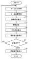
- FIG. 7is a flow chart showing a weighing method for weighing the load in the bucket 6 based on the embodiment.
- the boom pressure P ⁇is acquired (step S1).
- the pressure acquisition unit 30areceives an output of a detection signal indicating the head pressure of the boom cylinder 16 from the pressure sensor 28a.
- the pressure acquisition unit 30areceives an output of a detection signal indicating the bottom pressure of the boom cylinder 16 from the pressure sensor 28b.
- the pressure acquisition unit 30acalculates the differential pressure (boom pressure P ⁇ ) between the head pressure and the bottom pressure of the boom cylinder 16.
- the pressure acquisition unit 30aoutputs the calculated boom pressure P ⁇ signal to the instantaneous load calculation unit 30c.
- the angle acquisition unit 30breceives an output of a detection signal indicating the boom angle ⁇ 1 from the first angle detector 29.
- the angle acquisition unit 30boutputs a signal indicating the acquired boom angle ⁇ 1 to the instantaneous load calculation unit 30c.
- the instantaneous loadis calculated (step S3).
- the instantaneous load calculation unit 30chas a boom angle ⁇ 1 output from the angle acquisition unit 30b when the bucket 6 is empty, the bucket 6 is fully loaded, and the bucket 6 is halved.
- the boom pressure P ⁇ in the case ofis obtained.
- the instantaneous load calculation unit 30cdetermines the load WA when the bucket 6 is empty, the load WC when the bucket 6 is fully loaded, and the instantaneous load when the bucket 6 is 1/2 loaded.
- the instantaneous load W in the bucket 6 corresponding to the boom pressure P ⁇ output from the pressure acquisition unit 30ais calculated by performing linear interpolation as appropriate.
- step S4the period in which the parameters related to the instantaneous load W fluctuate with time is determined (step S4).
- the parameter related to the instantaneous load W in the embodimentrefers to the instantaneous load W itself or the boom pressure P ⁇ .
- FIG. 8is a graph showing the fluctuation of the instantaneous load with time.
- the horizontal axisis time and the vertical axis is the instantaneous load W.
- the cycle determination unit 30dcreates the graph shown in FIG. 8 by plotting the instantaneous load W calculated at each time.
- the instantaneous load Wfluctuates periodically with time.
- the instantaneous load Wfluctuates so as to fluctuate at regular intervals.
- the cycle determination unit 30ddetermines the time T1 from the first peak point PK1 at which the instantaneous load W becomes maximum to the second peak point PK2 at which the instantaneous load W becomes maximum as the period of fluctuation of the instantaneous load W with respect to time.
- the average load calculation unit 30ecalculates the average load (average load AV1 shown in FIG. 8) by averaging the instantaneous loads W at a plurality of times within the cycle determined in the previous step S4. Even if the average load calculation unit 30e calculates the average load by averaging the instantaneous load W calculated within the time T1 from the first peak point PK1 to the second peak point PK2 shown in FIG. Good.
- step S4even if the instantaneous load W calculated at each time is plotted on a graph in which the horizontal axis is time and the vertical axis is boom pressure P ⁇ , the period of fluctuation of the instantaneous load W with respect to time is determined. Good.
- the average loadmay be calculated by averaging the boom pressure P ⁇ calculated within the determined cycle.
- FIG. 5shows a load value in the bucket 6 corresponding to the average value of the boom pressure P ⁇ calculated within the time T1 from the first peak point PK1 to the second peak point PK2 shown in FIG. It may be calculated as an average load by linear interpolation using the graph.
- step S6the provisional load value is displayed (step S6).
- the average load calculation unit 30eoutputs the average load calculated in step S5 to the load output unit 30f as a provisional load value.
- the load output unit 30foutputs the provisional load value output from the average load calculation unit 30e to the display unit 40.
- the display unit 40displays the provisional load value on a screen or the like.
- step S7it is determined whether or not the weighing is completed.
- a third peak point PK3, a fourth peak point PK4, and a fifth peak point PK5are shown. If the time when the fifth peak point PK5 is seen has already passed at the time of the determination in step S7, the average load for four cycles corresponding to the time between the five peak points has already been calculated. It is judged that the measurement is completed by calculating the average load for 4 cycles.
- the weighing of the load L in the bucket 6can be completed in a short time because the productivity of the excavation and loading operation by the wheel loader 1 can be increased.
- the measurementis completed by the determination in step S7. For example, if the average load in the first cycle and the average load in the second cycle match, or if they do not exactly match but the difference is small enough, the calculation of the average load for two cycles is sufficient accuracy. It may be determined that the average load has been obtained, and the weighing may be completed. Further, for example, the weight of the load L may be determined with an average load of only one cycle, and the weighing may be completed.
- step S7If it is determined in step S7 that the weighing has not been completed yet (NO in step S7), the processes of steps S1 to S6 are repeated.
- the time T2 from the second peak point PK2 to the third peak point PK3is determined as the second cycle.
- the timeis calculated by averaging the instantaneous load W calculated within the time T2, calculating the load corresponding to the average value of the boom pressure P ⁇ calculated within the time T2, and the like.
- the average load in T2(average load AV2 shown in FIG. 8) is calculated. Further, the average load AV1 in the time T1 and the average load AV2 in the time T2 are averaged to obtain a provisional load value at this time.
- the time T3 from the third peak point PK3 to the fourth peak point PK4is determined as the third cycle.
- the timeis calculated by averaging the instantaneous load W calculated within the time T3, calculating the load corresponding to the average value of the boom pressure P ⁇ calculated within the time T3, and the like.
- the average load in T3(average load AV3 shown in FIG. 8) is calculated. Further, the average load AV1 in the time T1, the average load AV2 in the time T2, and the average load AV3 in the time T3 are averaged to obtain a provisional load value at this time.
- the time T4 from the fourth peak point PK4 to the fifth peak point PK5is determined as the fourth cycle.
- the timeis calculated by averaging the instantaneous load W calculated within the time T4, calculating the load corresponding to the average value of the boom pressure P ⁇ calculated within the time T4, and the like.
- the average load in T4(average load AV4 shown in FIG. 8) is calculated. Further, the average load AV1 in the time T1, the average load AV2 in the time T2, the average load AV3 in the time T3, and the average load AV4 in the time T4 are averaged to obtain the provisional load value at this time. To do.
- step S7if it is determined that the weighing is completed, the process proceeds to step S8 and the load confirmation value is displayed.
- the load output unit 30foutputs the provisional load value at the time when it is determined that the measurement is completed to the display unit 40 as the final load value.
- the display unit 40displays the load determination value on a screen or the like.
- the display unit 40can display the provisional load value and the final load value differently.
- the display unit 40may display the provisional load value and the final load value in different colors.
- the display unit 40may blink the provisional load value and continuously display the fixed load value.
- the wheel loader 1includes a first processing device 30 (controller).
- the first processing device 30includes an instantaneous load calculation unit 30c, a cycle determination unit 30d, and an average load calculation unit 30e.
- the instantaneous load calculation unit 30ccalculates the instantaneous load in the bucket 6.
- the cycle determination unit 30ddetermines the period in which the parameters related to the instantaneous load fluctuate with time.
- the average load calculation unit 30ecalculates the average load by averaging the instantaneous loads at a plurality of times in the cycle.
- the period for calculating the average load by averaging the instantaneous loads in the bucket 6correspond to the cycle of the parameter that fluctuates with time, the variation in the average load for each calculated period is reduced. It is not necessary to take an average for a long time in order to eliminate the variation in the average load, and the load in the bucket 6 can be accurately weighed by the processing in a short time.
- the cycle determination unit 30ddetermines the period from the peak of the parameter related to the instantaneous load to the next peak as the period of fluctuation.
- the average load calculation unit 30ecalculates the average load by averaging the instantaneous loads in the period from the peak of the parameter to the next peak. This makes it possible to easily determine the period in which the parameters related to the instantaneous load fluctuate with time.
- the cycle determination unit 30ddetermines a plurality of cycles in which the parameters related to the instantaneous load fluctuate with time.
- the average load calculation unit 30ecalculates a plurality of average loads by averaging the instantaneous loads at a plurality of times in each cycle, and further averages the plurality of average loads calculated for each of the plurality of cycles. By doing so, the accuracy of the average load can be improved, so that the load in the bucket 6 can be weighed more accurately.
- the pressure sensors 28a and 28bdetect the pressure of the hydraulic oil in the oil chamber of the boom cylinder 16.
- the cycle determination unit 30duses the pressure detected by the pressure sensors 28a and 28b as a time-varying parameter related to the instantaneous load in the bucket 6. As a result, the cycle determination unit 30d can accurately determine the period in which the oil pressure in the oil chamber of the boom cylinder 16 fluctuates with time.
- the time-varying parameters related to the instantaneous load in the bucket 6are not limited to the above pressure.
- the instantaneous load itself calculated based on the cylinder pressure detected by the pressure sensors 28a and 28b and the boom angle ⁇ 1 detected by the first angle detector 29may be used as a parameter.
- the angular velocity of the boom 14may be used as a parameter.
- the angular velocity of the boom 14can be calculated by differentiating the boom angle ⁇ 1 detected by the first angle detector 29 with respect to time.
- an angular velocity sensortypified by an IMU (Inertial Measurement Unit) may be attached to the boom 14, and the angular velocity sensor may directly detect the angular velocity of the boom 14.
- IMUInertial Measurement Unit
- the boom 14rises while the wheel loader 1 is running or stopped after the excavation is completed as shown in FIG.
- the instantaneous load in the bucket 6may be calculated during the ascent of the boom 14.
- the wheel loader 1travels toward a transport machine such as a dump truck with the load L loaded in the bucket 6.
- the instantaneous load in the bucket 6may be calculated while the wheel loader 1 is running.
- the vehicle body frame 2is provided with traveling wheels (front wheels 4a, rear wheels 4b) attached to the vehicle body frame 2, and the bucket 6 is attached to a wheel loader 1 arranged in front of the vehicle body frame 2 by the above-mentioned weighing method. By applying this, the load L in the bucket 6 of the wheel loader 1 can be accurately measured.
- the cycle of parameter variationmay be determined by other methods. For example, the period from the maximum value to the minimum value of the parameter that fluctuates with time, or the period from the minimum value to the maximum value is determined, and twice the determined period is determined as the period of fluctuation. You may.
- the extreme value (peak) of the fluctuationit is not always necessary to use the extreme value (peak) of the fluctuation in order to determine the cycle of the fluctuation of the parameter. For example, from the time when the instantaneous load that fluctuates with time becomes larger than the load value set as the provisional load value to the time when it becomes smaller than the provisional load value, then it becomes larger than the provisional load value.
- the period up to the point in timemay be determined as the period of fluctuation.
- the average loadwas calculated by averaging the instantaneous loads at a plurality of times within the cycle in which the parameters fluctuate.
- the plurality of instantaneous loads averaged to calculate the average loadmay be those calculated at a specific time.
- the average loadmay be calculated by averaging the instantaneous loads calculated at these two measurement points, with the time when the fluctuating parameter becomes maximum and the time when the variable parameter becomes minimum next as measurement points.
- the calculation of the plurality of instantaneous loadsmay be performed continuously with respect to time by shortening the time interval of calculation, or may be performed discretely with respect to time by making the time interval of calculation relatively long. Good.
- the wheel loader 1is provided with the first processing device 30 and the first processing device 30 mounted on the wheel loader 1 controls to weigh the load in the bucket 6
- the controller that controls the weighing of the load in the bucket 6does not necessarily have to be mounted on the wheel loader 1.
- FIG. 9is a schematic view of the system including the wheel loader 1.
- An external controller 130provided separately from the first processing device 30 mounted on the wheel loader 1 may configure a system for controlling the weighing of the load in the bucket 6.
- the controller 130may be arranged at the work site of the wheel loader 1 or may be arranged at a remote location away from the work site of the wheel loader 1.
- the wheel loader 1may be an unmanned vehicle.
- the wheel loader 1may not be provided with a cab for the operator to board and operate the wheel loader 1.
- the wheel loader 1does not have to be equipped with a maneuvering function by the operator on board.
- the wheel loader 1may be a work machine dedicated to remote control.
- the wheel loader 1may be operated by a radio signal from the remote control device.
- 1 wheel loader2 body frame, 2a front frame, 2b rear frame, 3 work machine, 4 traveling device, 4a front wheel, 4b rear wheel, 6 bucket, 14 boom, 16 boom cylinder, 19 bucket cylinder, 20 engine, 24 cylinder Drive unit, 25 work machine pump, 26 control valve, 28a, 28b first oil pressure detector, 29 first angle detector, 30 first processing device, 30a pressure acquisition unit, 30b angle acquisition unit, 30c instantaneous load calculation unit, 30d cycle determination unit, 30e average load calculation unit, 30f load output unit, 30j storage unit, 40 display unit, 48 second angle detector, 100 excavation target, 200 dump truck, L load, P boom pressure, PK1 to PK5 Peak point.
Landscapes
- Engineering & Computer Science (AREA)
- Mechanical Engineering (AREA)
- Mining & Mineral Resources (AREA)
- Civil Engineering (AREA)
- General Engineering & Computer Science (AREA)
- Structural Engineering (AREA)
- Physics & Mathematics (AREA)
- General Physics & Mathematics (AREA)
- Operation Control Of Excavators (AREA)
- Component Parts Of Construction Machinery (AREA)
Abstract
Description
Translated fromJapanese本開示は、作業機械、計量方法、および作業機械を含むシステムに関する。This disclosure relates to work machines, weighing methods, and systems including work machines.
特許文献1(特開2001-99701号公報)には、ホイールローダにおいて、積荷積載部に積載された荷の重量を計測する技術が提案されている。Patent Document 1 (Japanese Unexamined Patent Publication No. 2001-99701) proposes a technique for measuring the weight of a load loaded on a load loading unit in a wheel loader.
上記文献には、ブームを上昇させる油圧シリンダの油圧を所定サンプリング時間にわたってサンプリングし、このサンプリングを複数回繰り返し、ブーム角と、サンプリングした油圧のサンプリング時間における平均値とに基づいて積荷積載部に積載されたサンプリング重量を求め、複数回のサンプリングごとのサンプリング重量を平均して積載重量を算出する、と記載されている。In the above document, the hydraulic pressure of the hydraulic cylinder that raises the boom is sampled over a predetermined sampling time, and this sampling is repeated a plurality of times, and the product is loaded onto the cargo loading unit based on the boom angle and the average value of the sampled hydraulic pressure in the sampling time. It is stated that the sampling weight is obtained and the loading weight is calculated by averaging the sampling weights for each of a plurality of samplings.
上記文献に記載の手法では、複数回のサンプリングごとのサンプリング重量にバラツキが生じるため、このバラツキを解消して積載重量を精度よく算出するためには長時間平均を取る必要があった。In the method described in the above document, the sampling weight for each of a plurality of samplings varies. Therefore, in order to eliminate this variation and calculate the loaded weight accurately, it is necessary to take a long-term average.
本開示では、バケット内の荷を短時間で精度よく計量できる、作業機械、計量方法、および作業機械を含むシステムが提案される。In this disclosure, a system including a work machine, a weighing method, and a work machine that can accurately measure the load in the bucket in a short time is proposed.
本開示のある局面に従うと、バケットと、コントローラとを備える作業機械が提供される。コントローラは、バケット内の荷重に関連するパラメータが時間に対して変動する周期を決定する。コントローラは、周期内の複数の時刻における荷重を平均して、平均荷重を算出する。According to certain aspects of this disclosure, a work machine equipped with a bucket and a controller is provided. The controller determines the period by which the load-related parameters in the bucket fluctuate over time. The controller averages the loads at multiple times in the cycle to calculate the average load.
本開示のある局面に従うと、バケットを備える作業機械の、バケット内の荷を計量する計量方法が提供される。計量方法は、バケット内の荷重に関連するパラメータが時間に対して変動する周期を決定するステップと、周期内の複数の時刻における荷重を平均して平均荷重を算出するステップと、を備えている。According to certain aspects of this disclosure, a weighing method for weighing the load in a bucket of a work machine equipped with a bucket is provided. The weighing method includes a step of determining a period in which the load-related parameters in the bucket fluctuate with time, and a step of averaging the loads at a plurality of times in the period to calculate the average load. ..
本開示のある局面に従うと、バケットを有する作業機械と、コントローラとを備える、作業機械を含むシステムが提供される。コントローラは、バケット内の荷重に関連するパラメータが時間に対して変動する周期を決定する。コントローラは、周期内の複数の時刻における荷重を平均して、平均荷重を算出する。According to certain aspects of the present disclosure, a system including a work machine including a work machine having a bucket and a controller is provided. The controller determines the period by which the load-related parameters in the bucket fluctuate over time. The controller averages the loads at multiple times in the cycle to calculate the average load.
本開示に従えば、バケット内の荷を短時間で精度よく計量することができる。According to this disclosure, the load in the bucket can be accurately weighed in a short time.
以下、実施形態について図に基づいて説明する。以下の説明では、同一部品には、同一の符号を付している。それらの名称および機能も同じである。したがって、それらについての詳細な説明は繰り返さない。Hereinafter, the embodiment will be described with reference to the figure. In the following description, the same parts are designated by the same reference numerals. Their names and functions are the same. Therefore, the detailed description of them will not be repeated.
<全体構成>
実施形態においては、作業機械の一例としてホイールローダ1について説明する。図1は、実施形態に基づく作業機械の一例としてのホイールローダ1の側面図である。<Overall configuration>
In the embodiment, the
図1に示されるように、ホイールローダ1は、車体フレーム2と、作業機3と、走行装置4と、キャブ5とを備えている。車体フレーム2、キャブ5などからホイールローダ1の車体(作業機械本体)が構成されている。ホイールローダ1の車体には、作業機3および走行装置4が取り付けられている。As shown in FIG. 1, the
走行装置4は、ホイールローダ1の車体を走行させるものであり、走行輪4a、4bを含んでいる。ホイールローダ1は、車体の左右方向の両側に走行用回転体として走行輪4a、4bを備える装輪車両である。ホイールローダ1は、走行輪4a、4bが回転駆動されることにより自走可能であり、作業機3を用いて所望の作業を行うことができる。The
本明細書中において、ホイールローダ1が直進走行する方向を、ホイールローダ1の前後方向という。ホイールローダ1の前後方向において、車体フレーム2に対して作業機3が配置されている側を前方向とし、前方向と反対側を後方向とする。ホイールローダ1の左右方向とは、平坦な地面上にあるホイールローダ1を平面視したときに前後方向と直交する方向である。前方向を見て左右方向の右側、左側が、それぞれ右方向、左方向である。ホイールローダ1の上下方向とは、前後方向および左右方向によって定められる平面に直交する方向である。上下方向において地面のある側が下側、空のある側が上側である。In this specification, the direction in which the
車体フレーム2は、前フレーム2aと後フレーム2bとを含んでいる。前フレーム2aと後フレーム2bとにより、アーティキュレート構造の車体フレーム2が構成されている。The
前フレーム2aには、作業機3および左右一対の走行輪(前輪)4aが取り付けられている。作業機3は、車体の前方に配設されており、ホイールローダ1の車体によって支持されている。作業機3は、作業機ポンプ25(図2参照)からの作動油によって駆動される。作業機ポンプ25は、エンジン20により駆動され、吐出する作動油によって作業機3を作動させる油圧ポンプである。作業機3は、ブーム14と、作業具であるバケット6とを含んでいる。バケット6は、作業機3の先端に配置されている。A
ブーム14の基端部は、ブームピン9によって前フレーム2aに回転自在に取付けられている。バケット6は、ブーム14の先端に位置するバケットピン17によって、回転自在にブーム14に取付けられている。The base end portion of the
前フレーム2aとブーム14とは、一対のブームシリンダ16により連結されている。ブームシリンダ16は、油圧シリンダである。ブームシリンダ16の基端は、前フレーム2aに取り付けられている。ブームシリンダ16の先端は、ブーム14に取り付けられている。ブームシリンダ16が作業機ポンプ25(図2参照)からの作動油によって伸縮することによって、ブーム14が昇降する。ブームシリンダ16は、ブーム14を、ブームピン9を中心として上下に回転駆動する。ブーム14の昇降に伴って、ブーム14の先端に取り付けられたバケット6も昇降する。The
作業機3は、バケットシリンダ19をさらに含んでいる。バケットシリンダ19は、油圧シリンダであり、作業具であるバケット6を駆動する作業具シリンダである。バケットシリンダ19が作業機ポンプ25(図2参照)からの作動油によって伸縮することによって、バケット6が上下に回動する。バケットシリンダ19は、バケット6を、バケットピン17を中心として回転駆動する。The working
後フレーム2bには、キャブ5および左右一対の走行輪(後輪)4bが取り付けられている。キャブ5は、ブーム14の後方に配置されている。キャブ5は、車体フレーム2上に載置されている。キャブ5内には、オペレータが着座するシートおよび後述する操作装置などが配置されている。A
図2は、実施形態に従うホイールローダ1を含む全体システムの構成を示す概略ブロック図である。FIG. 2 is a schematic block diagram showing the configuration of the entire system including the
ホイールローダ1は、エンジン20、動力取り出し部22、動力伝達機構23、シリンダ駆動部24、第一角度検出器29、第二角度検出器48、および第1処理装置30(コントローラ)を備えている。The
エンジン20は、たとえばディーゼルエンジンである。エンジン20は、エンジンフード7(図1)に覆われた収納空間内に収納されている。エンジン20の出力は、エンジン20のシリンダ内に噴射する燃料量を調整することにより制御される。エンジン20には、回転センサ32が設けられている。回転センサ32は、エンジン20内部の回転軸の回転数を検出する。回転センサ32は、回転数を示す検出信号を第1処理装置30に出力する。The
動力取り出し部22は、エンジン20の出力を、動力伝達機構23とシリンダ駆動部24とに振り分ける装置である。動力伝達機構23は、エンジン20からの駆動力を前輪4aおよび後輪4bに伝達する機構であり、たとえばトランスミッションである。ホイールローダ1においては、前フレーム2aに取り付けられた前輪4aと、後フレーム2bに取り付けられた後輪4bとの両方が、駆動力を受けてホイールローダ1を走行させる駆動輪を構成している。動力伝達機構23は、入力軸21の回転を変速して出力軸23aに出力する。The power take-out
シリンダ駆動部24は、作業機ポンプ25および制御弁26を有している。エンジン20の出力は、動力取り出し部22を介して、作業機ポンプ25に伝達される。作業機ポンプ25から吐出された作動油は、制御弁26を介して、ブームシリンダ16およびバケットシリンダ19に供給される。The
ブームシリンダ16には、ブームシリンダ16の油室内の油圧(シリンダ圧力)を検出するための第一油圧検出器28a、28bが取り付けられている。ホイールローダ1は、第一油圧検出器28a、28bを含んでいる。第一油圧検出器28a、28bは、ブームシリンダ16のシリンダ圧力を検知する、実施形態のシリンダ圧力検知部に相当する。第一油圧検出器28a、28bは、たとえばヘッド圧検出用の圧力センサ28aと、ボトム圧検出用の圧力センサ28bとを有している。The
圧力センサ28aは、ブームシリンダ16のヘッド側(ブームシリンダ16のピストンロッドが出ている側)に取り付けられている。圧力センサ28aは、ブームシリンダ16のシリンダヘッド側油室内の作動油の圧力(ヘッド圧)を検出することができる。圧力センサ28aは、ブームシリンダ16のヘッド圧を示す検出信号を第1処理装置30に出力する。The
圧力センサ28bは、ブームシリンダ16のボトム側(ブームシリンダ16のピストンロッドが出ていない側)に取り付けられている。圧力センサ28bは、ブームシリンダ16のシリンダボトム側油室内の作動油の圧力(ボトム圧)を検出することができる。圧力センサ28bは、ブームシリンダ16のボトム圧を示す検出信号を第1処理装置30に出力する。The
第一角度検出器29は、たとえば、ブームピン9に取り付けられたポテンショメータである。第一角度検出器29は、ブーム14の持ち上がり角度を表すブーム角度を検出する。第一角度検出器29は、ブーム角度を示す検出信号を第1処理装置30に出力する。The
具体的には、図1に示すように、ブーム基準線Aは、ブームピン9の中心とバケットピン17の中心とを通る直線である。ブーム角度θ1は、ブームピン9の中心から前方に延びる水平線Hと、ブーム基準線Aとの成す角度である。ブーム基準線Aが水平である場合をブーム角度θ1=0°と定義する。ブーム基準線Aが水平線Hよりも上方にある場合にブーム角度θ1を正とする。ブーム基準線Aが水平線Hよりも下方にある場合にブーム角度θ1を負とする。Specifically, as shown in FIG. 1, the boom reference line A is a straight line passing through the center of the boom pin 9 and the center of the
第一角度検出器29は、ブームシリンダ16に配置されたストロークセンサであってもよい。第一角度検出器29は、ホイールローダ1の車体に対するブーム14の角度を表すブーム角度θ1を検知する、実施形態のブーム角度検知部に相当する。The
第二角度検出器48は、たとえばポテンショメータである。第二角度検出器48は、ブーム14に対するバケット6の角度を表すバケット角度を検出する。第二角度検出器48は、バケット角度を示す検出信号を第1処理装置30に出力する。第二角度検出器48は、近接スイッチであってもよい。または第二角度検出器48は、バケットシリンダ19に配置されたストロークセンサであってもよい。The
図2に示されるように、ホイールローダ1は、キャブ5内に、操作装置49を備えている。操作装置49は、オペレータによって操作される操作部材49aと、操作部材49aの位置を検出して検出結果を第1処理装置30に出力する検出センサ49bとを含んでいる。操作装置49は、車両の前進および後進の切り換え、エンジン20の目標回転速度の設定、ホイールローダ1の減速力の操作、ブーム14の上げ動作および下げ動作、動力伝達機構23における入力軸21から出力軸23aへの変速の制御、バケット6のチルト動作およびダンプ動作、前フレーム2aの後フレーム2bに対する屈曲(アーティキュレート)などを指示するために、オペレータによって操作される。As shown in FIG. 2, the
第1処理装置30は、RAM(Random Access Memory)、ROM(Read Only Memory)などの記憶装置と、CPU(Central Processing Unit)などの演算装置を含むマイクロコンピュータで構成されている。第1処理装置30は、エンジン20、作業機3(ブームシリンダ16、バケットシリンダ19など)、動力伝達機構23、表示部40などの動作を制御する、ホイールローダ1のコントローラの機能の一部として実現されてもよい。The
第1処理装置30には、第一角度検出器29によって検出されるブーム角度θ1の信号と、第二角度検出器48によって検出されるバケット角度の信号と、圧力センサ28aによって検出されるブームシリンダ16のヘッド圧の信号と、圧力センサ28bによって検出されるブームシリンダ16のボトム圧の信号と、が主に入力される。The
第1処理装置30は、記憶部30jを有している。記憶部30jは、ホイールローダ1の各種の動作を制御するためのプログラムを格納する。第1処理装置30は、記憶部30jに格納されているプログラムに基づいて、ホイールローダ1の動作を制御するための各種処理を実行する。記憶部30jは、不揮発性のメモリであり、必要なデータを記憶する領域として設けられている。The
ホイールローダ1は、表示部40を備えている。表示部40は、キャブ5に配置された、オペレータが視認するモニタである。表示部40は、情報を表示する。表示部40はたとえば、第1処理装置30によって算出されたバケット6内の荷の重量に関する情報を表示する。The
<第1処理装置30内の機能ブロック>
図2に示される第1処理装置30は、ブーム圧力、すなわち、圧力センサ28aにより検出されたヘッド圧と圧力センサ28bにより検出されたボトム圧との差圧を算出する機能を有する。第1処理装置30は、ブーム圧力およびブーム角度θ1に基づいて、バケット6内の瞬時荷重を算出する機能を有する。また第1処理装置30は、瞬時荷重を平均することにより、バケット6内の荷の重量を算出する機能を有する。以下、上記機能を有する第1処理装置30の機能ブロックについて説明する。<Functional block in the
The
図3は、第1処理装置30内の機能ブロックを示す図である。図3に示されるように、第1処理装置30は、圧力取得部30aと、角度取得部30bと、瞬時荷重算出部30cと、周期決定部30dと、平均荷重算出部30eと、荷重出力部30fと、記憶部30jとを主に有している。FIG. 3 is a diagram showing a functional block in the
圧力取得部30aは、圧力センサ28aから、ブームシリンダ16のヘッド圧を示す検出信号の出力を受ける。圧力取得部30aは、圧力センサ28bから、ブームシリンダ16のボトム圧を示す検出信号の出力を受ける。圧力取得部30aは、取得したブームシリンダ16のヘッド圧およびボトム圧を示す信号を、周期決定部30dへ出力する。また圧力取得部30aは、ブームシリンダ16のヘッド圧とボトム圧との差圧(ブーム圧力)を算出する。圧力取得部30aは、その算出したブーム圧力の信号を、瞬時荷重算出部30cへ出力する。The pressure acquisition unit 30a receives an output of a detection signal indicating the head pressure of the
角度取得部30bは、第一角度検出器29から、ブーム角度θ1を示す検出信号の出力を受ける。角度取得部30bは、取得したブーム角度θ1を示す信号を、瞬時荷重算出部30cへ出力する。The
瞬時荷重算出部30cは、角度取得部30bから出力されたブーム角度θ1を示す信号と、圧力取得部30aから出力されたブーム圧力を示す信号とに基づいて、バケット6内の瞬時荷重を算出する。瞬時荷重算出部30cにおける瞬時荷重の算出方法は、図4および図5を用いて後に詳細に説明する。瞬時荷重算出部30cにおいて算出されたバケット6内の瞬時荷重を示す信号は、周期決定部30dへ出力され、また平均荷重算出部30eへ出力される。The instantaneous load calculation unit 30c calculates the instantaneous load in the
周期決定部30dは、瞬時荷重算出部30cにおいて算出された瞬時荷重、または、圧力取得部30aにおいて算出されたブーム圧力の、時間に対する変動を特定する。周期決定部30dは、当該特定した変動に基づいて、時間に対する変動の周期を決定する。The
たとえば周期決定部30dは、横軸を時間、縦軸をブーム圧力とするグラフに、各時刻において算出されたブーム圧力をプロットする。周期決定部30dは、ブーム圧力の時間に対する推移から、ブーム圧力が時間に対して変動する周期を決定する。たとえば、ブーム圧力が減衰振動する波形を示す場合に、その波形の極大値から次の極大値までの期間を、ブーム圧力の変動の周期とすることができる。For example, the
周期決定部30dは、このようにして決定した周期を、平均荷重算出部30eへ出力する。The
平均荷重算出部30eは、周期決定部30dにおいて決定された周期内の、複数の時刻における瞬時荷重を平均して、平均荷重を算出する。平均荷重算出部30eは、算出した平均荷重を、記憶部30jおよび荷重出力部30fへ出力する。The average load calculation unit 30e calculates the average load by averaging the instantaneous loads at a plurality of times within the cycle determined by the
記憶部30jは、平均荷重算出部30eから出力された平均荷重を記憶する。荷重出力部30fは、平均荷重算出部30eから出力された平均荷重を、表示部40に出力する。表示部40は、平均荷重を画面などに表示する。The
<瞬時荷重の算出方法>
次に、瞬時荷重の算出方法の一例について説明する。<Calculation method of instantaneous load>
Next, an example of a method for calculating the instantaneous load will be described.
図4は、瞬時荷重ごとのブーム角度θ1とブーム圧力Pτとの関係の一例を示すグラフである。図4のグラフにおける横軸はブーム角度θ1、縦軸はブーム圧力Pτである。図4において、カーブA、B、Cはそれぞれ、バケット6が空、1/2積載、満杯積載の場合を示している。予め計測された2個以上の瞬時荷重におけるブーム角度θ1とブーム圧力Pτとの関係のグラフに基づき、図4に示すように、ブーム角度θ1ごとの瞬時荷重とブーム圧力Pτとの関係のグラフを求めることができる。FIG. 4 is a graph showing an example of the relationship between the boom angle θ1 and the boom pressure Pτ for each instantaneous load. In the graph of FIG. 4, the horizontal axis is the boom angle θ1, and the vertical axis is the boom pressure Pτ. In FIG. 4, curves A, B, and C show the case where the
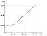
ある時刻におけるブーム角度θ1とブーム圧力Pτとが判明すると、その時刻での瞬時荷重を求めることができる。たとえば、図4に示されるように、ある時刻mkにおいてブーム角度θ1=θk、ブーム圧力Pτ=Pτkであったとすると、図5からその時刻mkにおける瞬時荷重WNを求めることが可能となる。図5は、ブーム角度θ1=θkにおける、ブーム圧力Pτと荷重Wとの関係を示すグラフである。図5のグラフにおける横軸はブーム圧力Pτ、縦軸は荷重Wである。Once the boom angle θ1 and boom pressure Pτ at a certain time are known, the instantaneous load at that time can be obtained. For example, as shown in FIG. 4, if the boom angle θ1 = θk and the boom pressure Pτ = Pτk at a certain time mk, it is possible to obtain the instantaneous load WN at that time mk from FIG. FIG. 5 is a graph showing the relationship between the boom pressure Pτ and the load W at the boom angle θ1 = θk. In the graph of FIG. 5, the horizontal axis is the boom pressure Pτ, and the vertical axis is the load W.
図4に示されるように、PτAとは、ブーム角度θ1=θkにおける、バケット6が空の場合のブーム圧力である。PτCとは、ブーム角角度θ1=θkにおける、バケット6が満杯積載の場合のブーム圧力である。図5に示されるWAとは、ブーム角度θ1=θkにおける、バケット6が空の場合の荷重である。またWCとは、ブーム角度θ1=θkにおける、バケット6が満杯積載の場合の荷重である。As shown in FIG. 4, PτA is the boom pressure when the
図5に示されるように、PτkがPτAとPτCとの間に位置する場合、線形補間を行うことにより、時刻mkにおける瞬時荷重WNを決定することができる。または、このような関係を予め記憶した数値テーブルに基づいて、瞬時荷重WNを求めることも可能である。As shown in FIG. 5, when Pτk is located between PτA and PτC, the instantaneous load WN at the time mk can be determined by performing linear interpolation. Alternatively, it is also possible to obtain the instantaneous load WN based on a numerical table in which such a relationship is stored in advance.
バケット6内の瞬時荷重の算出方法は、図4,5に示される例に限られない。ブーム圧力およびブーム角度θ1に加えて、またはこれらに代えて、バケットシリンダ19のヘッド圧とボトム圧との差圧、バケット角度、作業機3の寸法などを、バケット6内の瞬時荷重を算出するためのパラメータとして考慮することができる。これらのパラメータを考慮してバケット6内の瞬時荷重を算出することにより、より精度の高い荷重の算出が可能になる。The method of calculating the instantaneous load in the
<掘削動作>
実施形態のホイールローダ1は、土砂などの掘削対象物100をバケット6に掬い取る掘削動作と、バケット6内の荷L(掘削対象物100)をダンプトラックの荷台(被積込み対象)などの運搬機械に積み込む積込動作とを実行する。ホイールローダ1は、掘削動作と積込動作とを繰り返して、掘削対象物100を掘削し、ダンプトラックなどの運搬機械に掘削対象物100を積み込んでいる。図6は、実施形態に基づくホイールローダ1の掘削動作の例を示す模式図である。<Excavation operation>
The
図6(A)に示されるように、ホイールローダ1は、掘削対象物100に向かって前進する。この前進工程において、オペレータは、ブームシリンダ16およびバケットシリンダ19を操作して、作業機3をブーム14の先端が低い位置にありバケット6の底面が水平を向いた掘削姿勢にして、ホイールローダ1を掘削対象物100に向けて前進させる。As shown in FIG. 6A, the
図6(B)に示されるように、バケット6の刃先6a(図1)が掘削対象物100に食い込むまで、オペレータはホイールローダ1を前進させる。その後オペレータは、ブームシリンダ16を操作してバケット6を上昇させるとともに、バケットシリンダ19を操作してバケット6をチルトバックさせる。この掘削工程により、バケット6内に掘削対象物100が掬い込まれる。そして、図6(C)に示される、掬込み完了後のバケット6が所定の高さ以上となった状態、たとえばバケット6が上がりきった状態となり、掘削完了となる。As shown in FIG. 6B, the operator advances the
ホイールローダ1の現在の作業工程が掘削工程であり作業機3が掘削作業中であるか、現在の作業工程が掘削工程ではなく作業機が掘削作業中でないかは、たとえば、ホイールローダ1を前後進させるオペレータの操作、作業機3に対するオペレータの操作、および作業機3のシリンダの現在の油圧についての判定条件の組み合わせを用いることにより、判定することができる。Whether the current work process of the
<バケット6内の荷Lの計量フロー>
本実施形態のホイールローダ1は、上記の掘削動作においてバケット6内に積載された荷Lの重量を計測し、計測した荷Lの重量を出力(表示部40に表示)する。たとえば、掘削完了後のホイールローダ1の走行中に、バケット6内の荷Lの計量が実行されてもよい。たとえば、ブーム14の上昇中に、バケット6内の荷Lの計量が実行されてもよい。ホイールローダ1が走行を停止している間に、ブーム14を上昇させて計量が行なわれてもよい。<Weighing flow of load L in
The
図7は、実施形態に基づくバケット6内の荷を計量する計量方法を示すフロー図である。FIG. 7 is a flow chart showing a weighing method for weighing the load in the
図7に示されるように、まず、ブーム圧力Pτが取得される(ステップS1)。圧力取得部30aは、圧力センサ28aから、ブームシリンダ16のヘッド圧を示す検出信号の出力を受ける。圧力取得部30aは、圧力センサ28bから、ブームシリンダ16のボトム圧を示す検出信号の出力を受ける。圧力取得部30aは、ブームシリンダ16のヘッド圧とボトム圧との差圧(ブーム圧力Pτ)を算出する。圧力取得部30aは、その算出したブーム圧力Pτの信号を、瞬時荷重算出部30cへ出力する。As shown in FIG. 7, first, the boom pressure Pτ is acquired (step S1). The pressure acquisition unit 30a receives an output of a detection signal indicating the head pressure of the
次に、ブーム角度θ1が取得される(ステップS2)。角度取得部30bは、第一角度検出器29から、ブーム角度θ1を示す検出信号の出力を受ける。角度取得部30bは、取得したブーム角度θ1を示す信号を、瞬時荷重算出部30cへ出力する。Next, the boom angle θ1 is acquired (step S2). The
次に、瞬時荷重が算出される(ステップS3)。図4を参照して、瞬時荷重算出部30cは、角度取得部30bから出力されたブーム角度θ1における、バケット6が空の場合、バケット6が満杯積載の場合、およびバケット6が1/2積載の場合のブーム圧力Pτを求める。図5を参照して、瞬時荷重算出部30cは、バケット6が空の場合の荷重WA、バケット6が満杯積載の場合の荷重WC、およびバケット6が1/2積載の場合の瞬時荷重を、適宜線形補間することにより、圧力取得部30aから出力されたブーム圧力Pτに対応するバケット6内の瞬時荷重Wを算出する。Next, the instantaneous load is calculated (step S3). With reference to FIG. 4, the instantaneous load calculation unit 30c has a boom angle θ1 output from the
次に、瞬時荷重Wに関連するパラメータが時間に対して変動する周期が決定される(ステップS4)。実施形態における、瞬時荷重Wに関連するパラメータとは、瞬時荷重W自身、またはブーム圧力Pτを指す。Next, the period in which the parameters related to the instantaneous load W fluctuate with time is determined (step S4). The parameter related to the instantaneous load W in the embodiment refers to the instantaneous load W itself or the boom pressure Pτ.
図8は、時間に対する瞬時荷重の変動を示すグラフである。図8のグラフにおける横軸は時間、縦軸は瞬時荷重Wである。周期決定部30dは、各時刻において算出された瞬時荷重Wをプロットすることで、図8に示されるグラフを作成する。FIG. 8 is a graph showing the fluctuation of the instantaneous load with time. In the graph of FIG. 8, the horizontal axis is time and the vertical axis is the instantaneous load W. The
図8に示されるように、瞬時荷重Wは、時間に対して周期的に変動している。瞬時荷重Wは、一定周期で揺らぐように変動している。周期決定部30dは、瞬時荷重Wが極大となる第1のピーク点PK1から次に極大となる第2のピーク点PK2までの時間T1を、瞬時荷重Wの時間に対する変動の周期として決定する。As shown in FIG. 8, the instantaneous load W fluctuates periodically with time. The instantaneous load W fluctuates so as to fluctuate at regular intervals. The
次に、平均荷重が算出される(ステップS5)。平均荷重算出部30eは、前のステップS4で決定された周期内の、複数の時刻における瞬時荷重Wを平均して、平均荷重(図8に示される平均荷重AV1)を算出する。平均荷重算出部30eは、図8に示される第1のピーク点PK1から第2のピーク点PK2までの時間T1内において算出された瞬時荷重Wを平均することにより、平均荷重を算出してもよい。Next, the average load is calculated (step S5). The average load calculation unit 30e calculates the average load (average load AV1 shown in FIG. 8) by averaging the instantaneous loads W at a plurality of times within the cycle determined in the previous step S4. Even if the average load calculation unit 30e calculates the average load by averaging the instantaneous load W calculated within the time T1 from the first peak point PK1 to the second peak point PK2 shown in FIG. Good.
ステップS4の処理において、横軸を時間、縦軸をブーム圧力Pτとするグラフに、各時刻において算出された瞬時荷重Wをプロットして、瞬時荷重Wの時間に対する変動の周期を決定してもよい。この場合、ステップS5の処理では、その決定された周期内に算出されたブーム圧力Pτを平均することにより、平均荷重を算出してもよい。または、図8に示される第1のピーク点PK1から第2のピーク点PK2までの時間T1内に算出されたブーム圧力Pτの平均値に対応するバケット6内の荷重値を、図5に示されるグラフを用いた線形補間によって、平均荷重として算出してもよい。In the process of step S4, even if the instantaneous load W calculated at each time is plotted on a graph in which the horizontal axis is time and the vertical axis is boom pressure Pτ, the period of fluctuation of the instantaneous load W with respect to time is determined. Good. In this case, in the process of step S5, the average load may be calculated by averaging the boom pressure Pτ calculated within the determined cycle. Alternatively, FIG. 5 shows a load value in the
次に、荷重暫定値が表示される(ステップS6)。平均荷重算出部30eは、ステップS5で算出した平均荷重を、荷重暫定値として荷重出力部30fへ出力する。荷重出力部30fは、平均荷重算出部30eから出力された荷重暫定値を、表示部40に出力する。表示部40は、荷重暫定値を画面などに表示する。Next, the provisional load value is displayed (step S6). The average load calculation unit 30e outputs the average load calculated in step S5 to the load output unit 30f as a provisional load value. The load output unit 30f outputs the provisional load value output from the average load calculation unit 30e to the
次に、計量が終了したか否かが判断される(ステップS7)。図8には、上述した第1のピーク点PK1および第2のピーク点PK2に加えて、第3のピーク点PK3、第4のピーク点PK4、第5のピーク点PK5が示されている。ステップS7の判断の時点で、第5のピーク点PK5が見られる時刻を既に経過していれば、5つのピーク点間の時間に対応する4周期分の平均荷重が既に算出されており、この4周期分の平均荷重の算出をもって計量が終了したと判断される。Next, it is determined whether or not the weighing is completed (step S7). In FIG. 8, in addition to the above-mentioned first peak point PK1 and second peak point PK2, a third peak point PK3, a fourth peak point PK4, and a fifth peak point PK5 are shown. If the time when the fifth peak point PK5 is seen has already passed at the time of the determination in step S7, the average load for four cycles corresponding to the time between the five peak points has already been calculated. It is judged that the measurement is completed by calculating the average load for 4 cycles.
ステップS7の判断の時点で第5のピーク点PK5が見られる時刻を未だ経過していなくても、変動が収束してピーク点が観察されなくなった場合には、計量を終了する判断がなされる。また、ブーム角度θ1が計量に適した範囲から外れる、ブーム14の上昇が停止するなど、ホイールローダ1の動作が計量に適さないものとなった場合にも、計量を終了する判断がなされる。Even if the time when the fifth peak point PK5 is observed has not yet passed at the time of the determination in step S7, if the fluctuation converges and the peak point is no longer observed, the determination to end the weighing is made. .. Further, even when the operation of the
短時間でバケット6内の荷Lの計量を完了できれば、ホイールローダ1による掘削積込動作の生産性を高めることができるので好ましい。平均荷重を4周期分算出しなくても十分な精度の平均荷重が取得できたと判断された場合に、ステップS7の判断で計量を終了すると判断してもよい。たとえば、1周期目の平均荷重と2周期目の平均荷重とが、一致するか、厳密に一致はしないが十分に差が小さい場合には、2周期分の平均荷重の算出をもって十分な精度の平均荷重が取得できたと判断して、計量を終了してもよい。またたとえば、1周期のみの平均荷重で荷Lの重量を確定させて計量を終了してもよい。It is preferable if the weighing of the load L in the
ステップS7の判断において、計量が未だ終了していないと判断された場合(ステップS7においてNO)、ステップS1~S6の処理が繰り返される。If it is determined in step S7 that the weighing has not been completed yet (NO in step S7), the processes of steps S1 to S6 are repeated.
2回目のステップS4での処理では、第2のピーク点PK2から第3のピーク点PK3までの時間T2が、2つ目の周期として決定される。2回目のステップS5での処理では、時間T2内に算出された瞬時荷重Wを平均する、時間T2内に算出されたブーム圧力Pτの平均値に対応する荷重を算出するなどの処理により、時間T2内における平均荷重(図8に示される平均荷重AV2)が算出される。さらに、時間T1内における平均荷重AV1と、時間T2内における平均荷重AV2とを平均して、この時点での荷重暫定値とする。In the second processing in step S4, the time T2 from the second peak point PK2 to the third peak point PK3 is determined as the second cycle. In the second process in step S5, the time is calculated by averaging the instantaneous load W calculated within the time T2, calculating the load corresponding to the average value of the boom pressure Pτ calculated within the time T2, and the like. The average load in T2 (average load AV2 shown in FIG. 8) is calculated. Further, the average load AV1 in the time T1 and the average load AV2 in the time T2 are averaged to obtain a provisional load value at this time.
3回目のステップS4での処理では、第3のピーク点PK3から第4のピーク点PK4までの時間T3が、3つ目の周期として決定される。3回目のステップS5での処理では、時間T3内に算出された瞬時荷重Wを平均する、時間T3内に算出されたブーム圧力Pτの平均値に対応する荷重を算出するなどの処理により、時間T3内における平均荷重(図8に示される平均荷重AV3)が算出される。さらに、時間T1内における平均荷重AV1と、時間T2内における平均荷重AV2と、時間T3内における平均荷重AV3とを平均して、この時点での荷重暫定値とする。In the process in the third step S4, the time T3 from the third peak point PK3 to the fourth peak point PK4 is determined as the third cycle. In the third process in step S5, the time is calculated by averaging the instantaneous load W calculated within the time T3, calculating the load corresponding to the average value of the boom pressure Pτ calculated within the time T3, and the like. The average load in T3 (average load AV3 shown in FIG. 8) is calculated. Further, the average load AV1 in the time T1, the average load AV2 in the time T2, and the average load AV3 in the time T3 are averaged to obtain a provisional load value at this time.
4回目のステップS4での処理では、第4のピーク点PK4から第5のピーク点PK5までの時間T4が、4つ目の周期として決定される。4回目のステップS5での処理では、時間T4内に算出された瞬時荷重Wを平均する、時間T4内に算出されたブーム圧力Pτの平均値に対応する荷重を算出するなどの処理により、時間T4内における平均荷重(図8に示される平均荷重AV4)が算出される。さらに、時間T1内における平均荷重AV1と、時間T2内における平均荷重AV2と、時間T3内における平均荷重AV3と、時間T4内における平均荷重AV4とを平均して、この時点での荷重暫定値とする。In the processing in the fourth step S4, the time T4 from the fourth peak point PK4 to the fifth peak point PK5 is determined as the fourth cycle. In the processing in the fourth step S5, the time is calculated by averaging the instantaneous load W calculated within the time T4, calculating the load corresponding to the average value of the boom pressure Pτ calculated within the time T4, and the like. The average load in T4 (average load AV4 shown in FIG. 8) is calculated. Further, the average load AV1 in the time T1, the average load AV2 in the time T2, the average load AV3 in the time T3, and the average load AV4 in the time T4 are averaged to obtain the provisional load value at this time. To do.
ステップS7の判断において、計量が終了したと判断されると、ステップS8に進み、荷重確定値が表示される。荷重出力部30fは、計量が終了したと判断された時点での荷重暫定値を、荷重確定値として、表示部40に出力する。表示部40は、荷重確定値を画面などに表示する。In the determination of step S7, if it is determined that the weighing is completed, the process proceeds to step S8 and the load confirmation value is displayed. The load output unit 30f outputs the provisional load value at the time when it is determined that the measurement is completed to the
表示部40は、荷重暫定値と荷重確定値とを、異なる表示とすることができる。たとえば表示部40は、荷重暫定値と荷重確定値とを、異なる色で表示してもよい。たとえば表示部40は、荷重暫定値を点滅表示し、荷重確定値を連続表示してもよい。The
<作用および効果>
上述した実施形態に係る作業機械の特徴的な構成および作用効果についてまとめて説明すると、以下の通りである。なお、実施形態の構成に参照符号を付すが、これは一例である。<Action and effect>
The characteristic configurations and working effects of the work machine according to the above-described embodiment will be summarized as follows. Reference numerals are added to the configurations of the embodiments, but this is an example.
図2に示されるように、ホイールローダ1は、第1処理装置30(コントローラ)を備えている。図3に示されるように、第1処理装置30は、瞬時荷重算出部30cと、周期決定部30dと、平均荷重算出部30eとを有している。図7に示されるように、瞬時荷重算出部30cは、バケット6内の瞬時荷重を算出する。周期決定部30dは、瞬時荷重に関連するパラメータが時間に対して変動する周期を決定する。平均荷重算出部30eは、周期内の複数の時刻における瞬時荷重を平均して平均荷重を算出する。As shown in FIG. 2, the
バケット6内の瞬時荷重を平均して平均荷重を算出する期間を、時間に対して変動するパラメータの周期に対応させることにより、算出する期間毎の平均荷重のバラツキが低減される。平均荷重のバラツキを解消するために長時間平均を取る必要がなく、短時間の処理でバケット6内の荷を精度よく計量することができる。By making the period for calculating the average load by averaging the instantaneous loads in the
図8に示されるように、周期決定部30dは、瞬時荷重に関連するパラメータのピークから次のピークまでの期間を変動の周期として決定する。平均荷重算出部30eは、パラメータのピークから次のピークまでの期間における瞬時荷重を平均して、平均荷重を算出する。これにより、瞬時荷重に関連するパラメータが時間に対して変動する周期を、容易に決定することができる。As shown in FIG. 8, the
図7,8に示されるように、周期決定部30dは、瞬時荷重に関連するパラメータが時間に対して変動する周期を、複数決定する。平均荷重算出部30eは、各々の周期内の複数の時刻における瞬時荷重を平均して複数の平均荷重を算出し、複数の周期毎に算出された複数の平均荷重をさらに平均する。このようにすれば、平均荷重の精度を向上できるので、バケット6内の荷をより精度よく計量することができる。As shown in FIGS. 7 and 8, the
図2,3に示されるように、圧力センサ28a,28bは、ブームシリンダ16の油室内の作動油の圧力を検出する。図8に示されるように、周期決定部30dは、圧力センサ28a,28bにより検知された圧力を、バケット6内の瞬時荷重に関連する、時間に対して変動するパラメータとして用いる。これにより、周期決定部30dは、ブームシリンダ16の油室内の油圧が時間に対して変動する周期を、精度よく決定することができる。As shown in FIGS. 2 and 3, the
バケット6内の瞬時荷重に関連する、時間に対して変動するパラメータは、上記の圧力に限られない。圧力センサ28a,28bによって検出されるシリンダ圧力と第一角度検出器29によって検出されるブーム角度θ1とに基づいて算出される瞬時荷重自身を、パラメータとして用いてもよい。ブーム14の角速度をパラメータとして用いてもよい。ブーム14の角速度は、第一角度検出器29によって検出されるブーム角度θ1を時間で微分して算出することができる。または、ブーム14にIMU(Inertial Measurement Unit)に代表される角速度センサを取り付けて、この角速度センサによってブーム14の角速度を直接検出してもよい。The time-varying parameters related to the instantaneous load in the
図6に示される掘削完了後のホイールローダ1の走行中または停車中に、ブーム14が上昇する。バケット6内の瞬時荷重は、ブーム14の上昇中に算出されてもよい。バケット6内の瞬時荷重の経時的な変化が比較的小さい期間に瞬時荷重を算出することで、より正確な瞬時荷重の算出が可能となる。The
図6に示される掘削完了後に、ホイールローダ1は、ダンプトラックなどの運搬機械へ向かって、バケット6に荷Lを積載した状態で走行する。バケット6内の瞬時荷重は、ホイールローダ1の走行中に算出されてもよい。バケット6内の瞬時荷重の経時的な変化が比較的小さい期間に瞬時荷重を算出することで、より正確な瞬時荷重の算出が可能となる。After the excavation shown in FIG. 6 is completed, the
車体フレーム2と、車体フレーム2に取り付けられた走行輪(前輪4a、後輪4b)とを備え、バケット6は車体フレーム2の前方に配設されているホイールローダ1に、上述した計量方法を適用することで、ホイールローダ1のバケット6内の荷Lを精度よく計量することができる。The
これまでの実施形態の説明では、時間に対して変動するパラメータの極大値から次の極大値の期間を変動の周期として決定する例について説明した。パラメータの変動の周期は、他の手法によって決定されてもよい。たとえば、時間に対して変動するパラメータの極大値から極小値までの期間、または極小値から極大値までの期間を決定して、この決定された期間の2倍の時間を、変動の周期として決定してもよい。In the explanation of the embodiments so far, an example of determining the period of the next maximum value from the maximum value of the parameter that fluctuates with time as the period of fluctuation has been described. The cycle of parameter variation may be determined by other methods. For example, the period from the maximum value to the minimum value of the parameter that fluctuates with time, or the period from the minimum value to the maximum value is determined, and twice the determined period is determined as the period of fluctuation. You may.
パラメータの変動の周期を決定するために、変動の極値(ピーク)を必ずしも用いなくてもよい。たとえば、時間に対して変動する瞬時荷重が、荷重暫定値として設定されている荷重値よりも大きくなる時点から、荷重暫定値よりも小さくなる時点を経過して、次に荷重暫定値よりも大きくなる時点までの期間を、変動の周期として決定してもよい。It is not always necessary to use the extreme value (peak) of the fluctuation in order to determine the cycle of the fluctuation of the parameter. For example, from the time when the instantaneous load that fluctuates with time becomes larger than the load value set as the provisional load value to the time when it becomes smaller than the provisional load value, then it becomes larger than the provisional load value. The period up to the point in time may be determined as the period of fluctuation.
実施形態では、パラメータが変動する周期内の複数の時刻における瞬時荷重を平均して平均荷重を算出した。平均荷重を算出するために平均される複数の瞬時荷重は、特定の時刻に算出されたものであってもよい。たとえば、変動するパラメータが極大となる時刻と次に極小となる時刻とを計測点として、これら2点の計測点において算出された瞬時荷重を平均して、平均荷重を算出してもよい。複数の瞬時荷重の算出は、算出の時間間隔を短くして時間に対して連続的に行なわれてもよく、算出の時間間隔を比較的長くして時間に対して離散的に行なわれてもよい。In the embodiment, the average load was calculated by averaging the instantaneous loads at a plurality of times within the cycle in which the parameters fluctuate. The plurality of instantaneous loads averaged to calculate the average load may be those calculated at a specific time. For example, the average load may be calculated by averaging the instantaneous loads calculated at these two measurement points, with the time when the fluctuating parameter becomes maximum and the time when the variable parameter becomes minimum next as measurement points. The calculation of the plurality of instantaneous loads may be performed continuously with respect to time by shortening the time interval of calculation, or may be performed discretely with respect to time by making the time interval of calculation relatively long. Good.
実施形態では、ホイールローダ1が第1処理装置30を備えており、ホイールローダ1に搭載されている第1処理装置30がバケット6内の荷を計量する制御をする例について説明した。バケット6内の荷を計量する制御をするコントローラは、必ずしもホイールローダ1に搭載されていなくてもよい。In the embodiment, an example in which the
図9は、ホイールローダ1を含むシステムの概略図である。ホイールローダ1に搭載された第1処理装置30とは別に設けられた外部のコントローラ130が、バケット6内の荷を計量する制御をするシステムを構成してもよい。コントローラ130は、ホイールローダ1の作業現場に配置されてもよく、ホイールローダ1の作業現場から離れた遠隔地に配置されてもよい。FIG. 9 is a schematic view of the system including the
実施形態では、ホイールローダ1はキャブ5を備えており、オペレータがキャブ5に搭乗する有人車両である例について説明した。ホイールローダ1は、無人車両であってもよい。ホイールローダ1は、オペレータが搭乗してホイールローダ1を操作するためのキャブを備えていなくてもよい。ホイールローダ1は、搭乗したオペレータによる操縦機能を搭載していなくてもよい。ホイールローダ1は、遠隔操縦専用の作業機械であってもよい。ホイールローダ1の操縦は、遠隔操縦装置からの無線信号により行なわれてもよい。In the embodiment, an example in which the
今回開示された実施形態はすべての点で例示であって制限的なものではないと考えられるべきである。本発明の範囲は上記した説明ではなくて請求の範囲によって示され、請求の範囲と均等の意味および範囲内でのすべての変更が含まれることが意図される。The embodiments disclosed this time should be considered to be exemplary in all respects and not restrictive. The scope of the present invention is shown by the claims rather than the above description, and it is intended to include all modifications within the meaning and scope equivalent to the claims.
1 ホイールローダ、2 車体フレーム、2a 前フレーム、2b 後フレーム、3 作業機、4 走行装置、4a 前輪、4b 後輪、6 バケット、14 ブーム、16 ブームシリンダ、19 バケットシリンダ、20 エンジン、24 シリンダ駆動部、25 作業機ポンプ、26 制御弁、28a,28b 第一油圧検出器、29 第一角度検出器、30 第1処理装置、30a 圧力取得部、30b 角度取得部、30c 瞬時荷重算出部、30d 周期決定部、30e 平均荷重算出部、30f 荷重出力部、30j 記憶部、40 表示部、48 第二角度検出器、100 掘削対象物、200 ダンプトラック、L 荷、P ブーム圧力、PK1~PK5 ピーク点。1 wheel loader, 2 body frame, 2a front frame, 2b rear frame, 3 work machine, 4 traveling device, 4a front wheel, 4b rear wheel, 6 bucket, 14 boom, 16 boom cylinder, 19 bucket cylinder, 20 engine, 24 cylinder Drive unit, 25 work machine pump, 26 control valve, 28a, 28b first oil pressure detector, 29 first angle detector, 30 first processing device, 30a pressure acquisition unit, 30b angle acquisition unit, 30c instantaneous load calculation unit, 30d cycle determination unit, 30e average load calculation unit, 30f load output unit, 30j storage unit, 40 display unit, 48 second angle detector, 100 excavation target, 200 dump truck, L load, P boom pressure, PK1 to PK5 Peak point.
Claims (11)
Translated fromJapanese前記バケット内の荷重に関連するパラメータが時間に対して変動する周期を決定し、前記周期内の複数の時刻における前記荷重を平均して平均荷重を算出する、コントローラと、を備える、作業機械。Bucket and
A work machine comprising a controller that determines a period in which parameters related to a load in the bucket fluctuate with time and averages the load at a plurality of times within the period to calculate an average load.
前記ブームを駆動するブームシリンダと、
前記ブームシリンダのシリンダ圧力を検知するシリンダ圧力検知部とをさらに備え、
前記コントローラは、前記シリンダ圧力検知部により検知された前記シリンダ圧力を前記パラメータとして用いる、請求項1から請求項4のいずれか1項に記載の作業機械。A boom that raises and lowers the bucket,
The boom cylinder that drives the boom and
Further provided with a cylinder pressure detecting unit for detecting the cylinder pressure of the boom cylinder.
The work machine according to any one of claims 1 to 4, wherein the controller uses the cylinder pressure detected by the cylinder pressure detection unit as the parameter.
前記コントローラは、前記ブームの角速度を前記パラメータとして用いる、請求項1から請求項4のいずれか1項に記載の作業機械。Equipped with a boom that raises and lowers the bucket
The work machine according to any one of claims 1 to 4, wherein the controller uses the angular velocity of the boom as the parameter.
前記コントローラは、前記ブームの上昇中に、前記荷重を算出する、請求項1から請求項6のいずれか1項に記載の作業機械。Equipped with a boom that raises and lowers the bucket
The work machine according to any one of claims 1 to 6, wherein the controller calculates the load while the boom is rising.
前記コントローラは、前記装輪車両の走行中に、前記荷重を算出する、請求項1から請求項7のいずれか1項に記載の作業機械。The work machine is a wheeled vehicle.
The work machine according to any one of claims 1 to 7, wherein the controller calculates the load while the wheeled vehicle is traveling.
前記車体フレームに取り付けられた走行輪とをさらに備え、
前記バケットは前記車体フレームの前方に配設されている、請求項1から請求項8のいずれか1項に記載の作業機械。Body frame and
Further equipped with a traveling wheel attached to the vehicle body frame,
The work machine according to any one of claims 1 to 8, wherein the bucket is arranged in front of the vehicle body frame.
前記バケット内の荷重に関連するパラメータが時間に対して変動する周期を決定するステップと、
前記周期内の複数の時刻における前記荷重を平均して平均荷重を算出するステップと、を備える、計量方法。A weighing method for weighing a load in a bucket of a work machine provided with a bucket.
The step of determining the period in which the load-related parameters in the bucket fluctuate with time, and
A weighing method comprising a step of averaging the loads at a plurality of times in the cycle to calculate an average load.
前記バケット内の荷重に関連するパラメータが時間に対して変動する周期を決定し、前記周期内の複数の時刻における前記荷重を平均して平均荷重を算出する、コントローラと、を備える、作業機械を含むシステム。A work machine with a bucket and
A work machine comprising a controller that determines a period in which parameters related to the load in the bucket fluctuate with time and averages the load at multiple times within the period to calculate the average load. Including system.
Priority Applications (3)
| Application Number | Priority Date | Filing Date | Title |
|---|---|---|---|
| CN202080075127.3ACN114599838B (en) | 2019-12-27 | 2020-12-02 | Work machine, metering method, and system including work machine |
| US17/776,250US20220389688A1 (en) | 2019-12-27 | 2020-12-02 | Work machine, weighing method, and system including work machine |
| EP20906951.7AEP4030002B1 (en) | 2019-12-27 | 2020-12-02 | Work machine, weighing method and system including a work machine |
Applications Claiming Priority (2)
| Application Number | Priority Date | Filing Date | Title |
|---|---|---|---|
| JP2019238196AJP7374763B2 (en) | 2019-12-27 | 2019-12-27 | Work machines, weighing methods, and systems containing work machines |
| JP2019-238196 | 2019-12-27 |
Publications (1)
| Publication Number | Publication Date |
|---|---|
| WO2021131547A1true WO2021131547A1 (en) | 2021-07-01 |
Family
ID=76573941
Family Applications (1)
| Application Number | Title | Priority Date | Filing Date |
|---|---|---|---|
| PCT/JP2020/044803CeasedWO2021131547A1 (en) | 2019-12-27 | 2020-12-02 | Work machine, measurement method, and system including work machine |
Country Status (5)
| Country | Link |
|---|---|
| US (1) | US20220389688A1 (en) |
| EP (1) | EP4030002B1 (en) |
| JP (1) | JP7374763B2 (en) |
| CN (1) | CN114599838B (en) |
| WO (1) | WO2021131547A1 (en) |
Families Citing this family (2)
| Publication number | Priority date | Publication date | Assignee | Title |
|---|---|---|---|---|
| JP7682004B2 (en)* | 2021-03-31 | 2025-05-23 | 株式会社小松製作所 | Calculation device and calculation method |
| DE102022111975A1 (en)* | 2022-05-12 | 2023-11-16 | Mts Schrode Ag | Method for determining a load on an excavator attachment and excavator |
Citations (3)
| Publication number | Priority date | Publication date | Assignee | Title |
|---|---|---|---|---|
| JPH0285725A (en)* | 1988-09-21 | 1990-03-27 | Shin Meiwa Ind Co Ltd | How to weigh the load on a freight vehicle |
| US5226496A (en)* | 1991-09-27 | 1993-07-13 | Pitney Bowes Inc. | Method and apparatus for fast determination of weights |
| JP2001099701A (en) | 1999-09-30 | 2001-04-13 | Komatsu Ltd | Loading weight measuring device for loaded vehicles |
Family Cites Families (8)
| Publication number | Priority date | Publication date | Assignee | Title |
|---|---|---|---|---|
| JPH0610378A (en)* | 1992-06-26 | 1994-01-18 | Komatsu Ltd | Work load detection device for excavator |
| JP2002332663A (en)* | 2001-05-09 | 2002-11-22 | Hitachi Constr Mach Co Ltd | Load measuring apparatus for hydraulic back hoe |
| JP4338678B2 (en)* | 2005-06-06 | 2009-10-07 | Tcm株式会社 | Load detection method and apparatus for work vehicle |
| US8667886B2 (en)* | 2009-12-04 | 2014-03-11 | Deere And Company | Variable output hydraulic actuator system |
| JP5604200B2 (en)* | 2010-07-10 | 2014-10-08 | 西日本高速道路ファシリティーズ株式会社 | Measuring device for weight of traveling vehicle |
| JP2014173949A (en)* | 2013-03-07 | 2014-09-22 | Hitachi Constr Mach Co Ltd | Load measuring device of work machine |
| US11511972B1 (en)* | 2019-09-26 | 2022-11-29 | Versatile, Inc. | System for tracking lifting events at a construction site |
| JP7374762B2 (en)* | 2019-12-27 | 2023-11-07 | 株式会社小松製作所 | Work machines, weighing methods, and systems containing work machines |
- 2019
- 2019-12-27JPJP2019238196Apatent/JP7374763B2/enactiveActive
- 2020
- 2020-12-02CNCN202080075127.3Apatent/CN114599838B/enactiveActive
- 2020-12-02EPEP20906951.7Apatent/EP4030002B1/enactiveActive
- 2020-12-02USUS17/776,250patent/US20220389688A1/enactivePending
- 2020-12-02WOPCT/JP2020/044803patent/WO2021131547A1/ennot_activeCeased
Patent Citations (3)
| Publication number | Priority date | Publication date | Assignee | Title |
|---|---|---|---|---|
| JPH0285725A (en)* | 1988-09-21 | 1990-03-27 | Shin Meiwa Ind Co Ltd | How to weigh the load on a freight vehicle |
| US5226496A (en)* | 1991-09-27 | 1993-07-13 | Pitney Bowes Inc. | Method and apparatus for fast determination of weights |
| JP2001099701A (en) | 1999-09-30 | 2001-04-13 | Komatsu Ltd | Loading weight measuring device for loaded vehicles |
Also Published As
| Publication number | Publication date |
|---|---|
| EP4030002A1 (en) | 2022-07-20 |
| CN114599838B (en) | 2024-01-19 |
| EP4030002A4 (en) | 2023-04-19 |
| JP7374763B2 (en) | 2023-11-07 |
| CN114599838A (en) | 2022-06-07 |
| JP2021105320A (en) | 2021-07-26 |
| EP4030002B1 (en) | 2025-03-12 |
| US20220389688A1 (en) | 2022-12-08 |
Similar Documents
| Publication | Publication Date | Title |
|---|---|---|
| AU2009221767B2 (en) | Adaptive payload monitoring system | |
| US8924094B2 (en) | System for work cycle detection | |
| US9938692B2 (en) | Wheel loader payload measurement system linkage acceleration compensation | |
| US5941921A (en) | Sensor feedback control for automated bucket loading | |
| JP6807293B2 (en) | Work machine | |
| US9091586B2 (en) | Payload determination system and method | |
| WO2006098645A1 (en) | Weighing device for excavator payloads | |
| KR102717651B1 (en) | Working machines and methods for controlling working machines | |
| US9043097B2 (en) | System and method for estimating machine pitch angle | |
| US20120201640A1 (en) | Mobile Working Machine with a Control Device, Comprising a Working Arm and Methods for Controlling the Operating Point of a Working Arm of a Mobile Working Machine | |
| WO2019171885A1 (en) | Work vehicle, system including work vehicle, and load weight calculation method for work vehicle | |
| WO2021131547A1 (en) | Work machine, measurement method, and system including work machine | |
| JP7374762B2 (en) | Work machines, weighing methods, and systems containing work machines | |
| KR20210111838A (en) | Working Machines, Systems and Control Methods of Working Machines | |
| AU2020224467A1 (en) | System, method, and device for calibrating work machine | |
| US20220341123A1 (en) | Work machine | |
| US12012727B2 (en) | System and method for estimating the weight of a load carried by an implement of a work vehicle | |
| US12163825B2 (en) | Work machine | |
| CA3195602A1 (en) | System and method for calibrating process to compute weight of material in dump bodies | |
| JPS63217024A (en) | Blade tilt control device |
Legal Events
| Date | Code | Title | Description |
|---|---|---|---|
| 121 | Ep: the epo has been informed by wipo that ep was designated in this application | Ref document number:20906951 Country of ref document:EP Kind code of ref document:A1 | |
| ENP | Entry into the national phase | Ref document number:2020906951 Country of ref document:EP Effective date:20220411 | |
| NENP | Non-entry into the national phase | Ref country code:DE |