WO2021131153A1 - Antistatic structure and air-conditioner - Google Patents
Antistatic structure and air-conditionerDownload PDFInfo
- Publication number
- WO2021131153A1 WO2021131153A1PCT/JP2020/031702JP2020031702WWO2021131153A1WO 2021131153 A1WO2021131153 A1WO 2021131153A1JP 2020031702 WJP2020031702 WJP 2020031702WWO 2021131153 A1WO2021131153 A1WO 2021131153A1
- Authority
- WO
- WIPO (PCT)
- Prior art keywords
- conductive member
- casing
- antistatic structure
- static electricity
- opening
- Prior art date
- Legal status (The legal status is an assumption and is not a legal conclusion. Google has not performed a legal analysis and makes no representation as to the accuracy of the status listed.)
- Ceased
Links
Images


Classifications
- F—MECHANICAL ENGINEERING; LIGHTING; HEATING; WEAPONS; BLASTING
- F24—HEATING; RANGES; VENTILATING
- F24F—AIR-CONDITIONING; AIR-HUMIDIFICATION; VENTILATION; USE OF AIR CURRENTS FOR SCREENING
- F24F13/00—Details common to, or for air-conditioning, air-humidification, ventilation or use of air currents for screening
- F24F13/20—Casings or covers
- F—MECHANICAL ENGINEERING; LIGHTING; HEATING; WEAPONS; BLASTING
- F24—HEATING; RANGES; VENTILATING
- F24F—AIR-CONDITIONING; AIR-HUMIDIFICATION; VENTILATION; USE OF AIR CURRENTS FOR SCREENING
- F24F1/00—Room units for air-conditioning, e.g. separate or self-contained units or units receiving primary air from a central station
- F24F1/0007—Indoor units, e.g. fan coil units
- F—MECHANICAL ENGINEERING; LIGHTING; HEATING; WEAPONS; BLASTING
- F24—HEATING; RANGES; VENTILATING
- F24F—AIR-CONDITIONING; AIR-HUMIDIFICATION; VENTILATION; USE OF AIR CURRENTS FOR SCREENING
- F24F11/00—Control or safety arrangements
- F24F11/89—Arrangement or mounting of control or safety devices
- H—ELECTRICITY
- H05—ELECTRIC TECHNIQUES NOT OTHERWISE PROVIDED FOR
- H05F—STATIC ELECTRICITY; NATURALLY-OCCURRING ELECTRICITY
- H05F3/00—Carrying-off electrostatic charges
- H05F3/02—Carrying-off electrostatic charges by means of earthing connections
- H—ELECTRICITY
- H05—ELECTRIC TECHNIQUES NOT OTHERWISE PROVIDED FOR
- H05K—PRINTED CIRCUITS; CASINGS OR CONSTRUCTIONAL DETAILS OF ELECTRIC APPARATUS; MANUFACTURE OF ASSEMBLAGES OF ELECTRICAL COMPONENTS
- H05K9/00—Screening of apparatus or components against electric or magnetic fields
- H05K9/0073—Shielding materials
- H05K9/0079—Electrostatic discharge protection, e.g. ESD treated surface for rapid dissipation of charges
Definitions
- This disclosurerelates to an antistatic structure and an air conditioner.
- a conductive thin-walled layeris provided on the surface of the main body portion where electronic components are exposed, and an extending portion is formed from the conductive thin-walled layer along the side surface of the main body portion, while the vicinity of the extending portion is formed.
- the ground portionsseparated by a small interval, the static electricity that is about to be charged in the electronic component is discharged from the conductive thin-walled layer to the ground through the ground portion (for example, Jitsukaihei No. 4-118598). See Gazette (Patent Document 1)).
- the above-mentioned antistatic structurehas a problem that the electronic component itself has a high risk of being damaged because static electricity is passed to the ground through the ground portion which is the ground potential of the electronic component mounted on the substrate of the main body.
- the designis poor because a conductive thin-walled layer is provided on the surface of the main body where the electronic components are exposed.
- an antistatic structurethat can release static electricity from the casing to the ground and an air conditioner equipped with the antistatic structure.
- the antistatic structure of the present disclosureis Casing and The elements arranged in the casing and It is provided on the inner surface of the casing and includes a first conductive member that allows static electricity to flow to the ground. At least a part of the first conductive member is provided around a region of the casing facing the element.
- the first conductive member provided on the inner surface of the casingis provided around the region facing the element of the casing, so that the static electricity applied to the casing is depleted. 1 Since the casing is allowed to flow to the ground via the conductive member, the static electricity of the casing can be released to the ground without flowing to the element side. Further, since the first conductive member for static electricity countermeasures is provided on the inner surface of the casing, the first conductive member cannot be seen from the outside, so that the design of the appearance can be maintained.
- An openingis provided in the region of the casing facing the element.
- the first conductive memberis provided around the opening of the casing.
- the first conductive memberis provided around the opening provided in the region facing the element of the casing, dust accumulates in the opening over time and static electricity easily flows into the opening.
- static electricitycan be passed to the ground via the first conductive member, and measures against static electricity on the element near the opening can be maintained for a long period of time.
- the first conductive memberis provided on the entire circumference of the opening of the casing.
- the first conductive memberis provided on the entire circumference of the opening of the casing, the effect of measures against static electricity on the element is improved.
- a second conductive memberarranged in the casing and electrically connected to the ground.
- the first conductive memberis electrically connected to the second conductive member in a non-contact manner.
- the first conductive memberis electrically connected to the second conductive member in a non-contact manner, the first conductive member and the second conductive member electrically connected to the ground
- the casingcan be easily removed without connecting directly with wiring, improving assembleability and maintainability.
- the first conductive memberhas an extension portion extending along the inner surface of the casing. In the first conductive member, the extension portion is closest to the second conductive member.
- the extension portion of the first conductive memberis closest to the second conductive member, so that the static electricity applied to the casing is applied to the extension portion of the first conductive member and the second conductive member. Since the static electricity is passed to the ground via the above, the path for flowing static electricity from the first conductive member to the ground can be easily set according to the arrangement of each component in the casing.
- the shortest distance between the first conductive member and the elementis longer than the shortest distance between the first conductive member and the second conductive member.
- the shortest distance between the first conductive member and the elementis longer than the shortest distance between the first conductive member and the second conductive member, so that static electricity does not flow through the element.
- Static electricitycan be discharged at a location where the first conductive member and the second conductive member are closest to each other so that the static electricity can be reliably flowed to the ground.
- the air conditioner of the present disclosureis It is characterized by having any one of the above antistatic structures.
- the present disclosureby providing the above-mentioned antistatic structure, it is possible to take antistatic measures by releasing the static electricity of the casing to the ground with a simple configuration for, for example, a temperature sensor or a humidity sensor arranged in the casing. ..
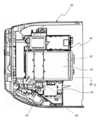
- FIG. 1is a front view of an indoor unit 1 of an air conditioner provided with an antistatic structure according to the first embodiment of the present disclosure.
- the air conditioner provided with the antistatic structure of the first embodimenthas an indoor unit 1 installed on a wall surface of the room.
- the indoor unit 1has a front panel 10, a front grill 20 to which the front panel 10 is attached, and a bottom frame (not shown) to which the front grill 20 is attached.
- An indoor heat exchanger, a drain pan, a cross flow fan, an electrical component unit 40 (shown in FIG. 2), and the likeare attached to this bottom frame.
- the front grill 20is an example of a casing.
- a horizontal flap 30is rotatably attached to an air outlet 20a provided on the front side and the lower side of the front grill 20.
- FIG. 2is a perspective view of the front grill 20 of the indoor unit 1. As shown in FIG. 2, the front grill 20 has a right side portion 21 and a left side portion 24. The electrical component unit 40 is housed in the vicinity of the right side portion 21 in the front grill 20.
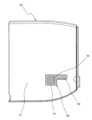
- FIG. 3is a right side view of the front grill 20, and an opening 22 composed of a plurality of slits 22a is provided on the lower side of the right side portion 21.
- reference numeral 60denotes a conductive tape 60 as an example of the first conductive member (see FIG. 5).
- FIG. 4shows a vertical cross-sectional view seen from the IV-IV line of FIG. 1, and the electrical component unit 40 is a resin base member 41 and a control board attached to the center of the right side of the base member 41. It has a 42, a metal cover 43 attached to the base member 41 and covering the control board 42, and a temperature / humidity sensor 50 attached to the right side of the base member 41 and below the control board 42.
- the metal cover 43is an example of the second conductive member.
- the temperature / humidity sensor 50is an example of an element, and detects the temperature and humidity of the indoor air.
- the opening 22is located in the region facing the temperature / humidity sensor 50.
- the temperature and humidity of the air flowing in from the opening 22are detected by the temperature / humidity sensor 50 (element).
- FIG. 5is a vertical cross-sectional view seen from the VV line of FIG.
- a square frame-shaped base portion 61is provided inside the right side portion 21 and on the entire circumference of the opening 22, and an extension portion 62 extending forward along the inner surface of the right side portion 21 so as to be separated from the opening 22. Is provided.
- the base portion 61 and the extension portion 62form a conductive tape 60.
- the conductive tape 60is used as the first conductive member, but the tape is not limited to the conductive tape, and may be a metal film formed by plating or the like, or a paint having conductivity.
- the front grill 20, the temperature / humidity sensor 50, the conductive tape 60, and the metal cover 43form an antistatic structure.
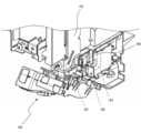
- FIG. 6shows a perspective view of the lower part of the electrical component unit 40 and the conductive tape 60
- FIG. 7shows a perspective view of the lower part of the electrical component unit 40.
- the front grill 20is omitted.
- the tip end side (hatched area in FIG. 6) of the extension portion 62 of the conductive tape 60is closest to the metal cover 43.
- FIG. 8shows the positional relationship between the electrical component unit 40 and the conductive tape 60
- FIG. 9is a perspective view of the metal cover 43 and the conductive tape 60.
- the metal cover 43is painted in gray for easy understanding.
- the space distance L between the tip end side of the extension portion 62 of the conductive tape 60 and the metal cover 43is 4.6 mm.
- the metal cover 43is electrically connected to ground E.
- the space distance between the opening 22 provided on the right side portion 21 of the front grill 20 and the temperature / humidity sensor 50 (element)is set to 6 mm.
- the space distance between the opening 22 and the temperature / humidity sensor 50 (element)is 6 mm, and the accurate temperature by the temperature / humidity sensor 50 (element) is set. While enabling the detection of humidity, measures against static electricity of the temperature / humidity sensor 50 (element) are taken.
- the temperature / humidity sensor 50 (element)may be placed closer to the opening 22 than the insulation distance (space distance) of 15 mm for a voltage of 15 kV, and the temperature / humidity sensor 50 (element) may be placed at a position where the temperature and humidity tracking performance is good. it can.
- a part of the conductive tape 60 (first conductive member) provided on the inner surface of the front grill 20 (casing)is the temperature / humidity sensor 50 (element) of the front grill 20.
- the static electricity applied to the front grill 20is allowed to flow to the ground E via the conductive tape 60 and the metal cover 43 (second conductive member) because it is provided around the region facing the front surface.
- the static electricity of the grill 20can be released to the earth E without flowing to the temperature / humidity sensor 50 side.
- the indoor unit 1 having the above configurationhad good static electricity test results in accordance with IEC standard 6100-4-2 and JIS standard 6100-4-2.
- the conductive tape 60 for antistatic measuresis provided on the inner surface of the front grill 20, the conductive tape 60 cannot be seen from the outside, so that the design of the appearance can be maintained.
- the conductive tape 60is provided around the opening 22 provided in the region of the front grill 20 facing the temperature / humidity sensor 50, dust easily accumulates in the opening 22 and static electricity easily flows into the opening 22 over time. Even so, static electricity can flow to the earth E through the conductive tape 60 and the metal cover 43, and the measures against static electricity on the temperature / humidity sensor 50 near the opening 22 can be maintained for a long period of time.
- the base portion 61 of the conductive tape 60is provided on the entire circumference of the opening 22 of the front grill 20, the effect of antistatic measures on the temperature / humidity sensor 50 is improved.
- the base portion 61 of the conductive tape 60is provided on the entire circumference of the opening 22 of the front grill 20, but the first conductive tape or the like is provided on a part around the opening 22 of the front grill 20. It may be provided with a member.
- the conductive tape 60is electrically connected to the metal cover 43 in a non-contact manner, the front surface of the conductive tape 60 and the earth E and the electrically connected metal cover 43 are not connected by wiring or the like.
- the structure of the grill 20can be easily removed, and the assembleability and maintainability are improved.
- the conductive tape 60 and the metal cover 43are electrically connected to each other via the atmosphere in a non-contact manner.
- the extension portion 62is closest to the metal cover 43 connected to the metal cover 43, so that the static electricity applied to the front grill 20 is transferred to the extension portion 62 and the metal cover of the conductive tape 60. Since the metal flows to the ground E via the 43, the path for flowing static electricity from the conductive tape 60 to the ground E can be easily set according to the arrangement of each component in the front grill 20 and the like.
- the shortest distance between the conductive tape 60 and the temperature / humidity sensor 50is longer than the shortest distance between the conductive tape 60 and the metal cover 43 connected to the earth E, static electricity is applied to the temperature / humidity sensor 50.
- the static electricitycan be discharged at the place where the conductive tape 60 and the metal cover 43 are closest to each other without flowing, and the electric tape can be surely flowed to the earth E.
- the static electricity of the front grill 20is grounded to the temperature / humidity sensor 50 arranged in the front grill 20 with a simple configuration. Antistatic measures can be taken by letting it escape to E.
- the antistatic structureis composed of the front grill 20, the temperature / humidity sensor 50, the conductive tape 60 (first conductive member), and the metal cover 43 (second conductive member). It is not necessary to have a sex member, and the first conductive member may be used as an antistatic structure in which a path for passing static electricity to the earth E is formed.
- the conductive tape 60(first conductive member) is electrically connected to the ground E via the metal cover 43 in a non-contact manner, whereas the second embodiment is performed.
- the first conductive member provided on the inner surface of the casing and the second conductive member arranged in the casing and connected to the earth Eare in contact with each other and electrically connected to each other. ..
- the static electricity applied to the casingis passed to the earth E via the first conductive member and the second conductive member.
- first conductive member and the second conductive membermay be electrically connected via a connecting member such as wiring.
- the antistatic structure of the second embodimenthas the same effect as the antistatic structure of the first embodiment.
- the air purifier of the third embodimentincludes a humidity sensor arranged in the casing. An opening is provided in a region of the casing facing the humidity sensor, and a first conductive member that allows static electricity to flow to the earth E is provided on the inner surface of the casing.
- the antistatic structure of the third embodimenthas the same effect as the antistatic structure of the first embodiment.
- the air conditioner and the air purifier provided with the antistatic structurehave been described, but the antistatic structure of the present invention is applied to other devices such as a remote controller having a built-in temperature sensor and the like. You may.
- an openingis provided in the region of the casing facing the temperature / humidity sensor 50 as an element and the humidity sensor, but the opening may not be provided and the first conductivity provided on the inner surface of the casing may be provided. At least a part of the member may be provided around the region of the casing facing the element.
- the antistatic structure in which the temperature / humidity sensor 50 and the humidity sensor are provided in the casinghas been described, but the element is not limited to this, and an odor sensor or an element other than the sensor may be used.
- the present inventionmay be applied to the provided antistatic structure.
- elements other than sensorsinclude components of WiFi (registered trademark) modules.
Landscapes
- Engineering & Computer Science (AREA)
- Chemical & Material Sciences (AREA)
- Combustion & Propulsion (AREA)
- Mechanical Engineering (AREA)
- General Engineering & Computer Science (AREA)
- Microelectronics & Electronic Packaging (AREA)
- Elimination Of Static Electricity (AREA)
- Air Filters, Heat-Exchange Apparatuses, And Housings Of Air-Conditioning Units (AREA)
- Air Conditioning Control Device (AREA)
Abstract
Description
Translated fromJapanese本開示は、静電気防止構造および空気調和機に関する。This disclosure relates to an antistatic structure and an air conditioner.
従来、静電気防止構造としては、電子部品が露出する本体部の表面に導電性薄肉層を設け、導電性薄肉層から本体部の側面に沿って延設部を形成する一方、延設部の近傍に、微小間隔だけ離れたグランド部を形成することにより、電子部品に帯電しようとした静電気を導電性薄肉層からグランド部を介してアースに流出させるものがある(例えば、実開平4-118598号公報(特許文献1)参照)。Conventionally, as an antistatic structure, a conductive thin-walled layer is provided on the surface of the main body portion where electronic components are exposed, and an extending portion is formed from the conductive thin-walled layer along the side surface of the main body portion, while the vicinity of the extending portion is formed. In addition, by forming the ground portions separated by a small interval, the static electricity that is about to be charged in the electronic component is discharged from the conductive thin-walled layer to the ground through the ground portion (for example, Jitsukaihei No. 4-118598). See Gazette (Patent Document 1)).
しかしながら、上記静電気防止構造では、本体部の基板に実装された電子部品のグランド電位であるグランド部を介して静電気をアースに流すため、電子部品そのものが破損するリスクが高いという問題がある。However, the above-mentioned antistatic structure has a problem that the electronic component itself has a high risk of being damaged because static electricity is passed to the ground through the ground portion which is the ground potential of the electronic component mounted on the substrate of the main body.
上記静電気防止構造では、電子部品が露出する本体部の表面に導電性薄肉層を設けているため、意匠性が悪い。In the above antistatic structure, the design is poor because a conductive thin-walled layer is provided on the surface of the main body where the electronic components are exposed.
本開示では、ケーシングの静電気をアースに逃がすようにできる静電気防止構造およびその静電気防止構造を備えた空気調和機を提案する。In this disclosure, we propose an antistatic structure that can release static electricity from the casing to the ground and an air conditioner equipped with the antistatic structure.
本開示の静電気防止構造は、
ケーシングと、
上記ケーシング内に配置された素子と、
上記ケーシングの内面に設けられ、静電気をアースに流す第1導電性部材と
を備え、
上記第1導電性部材の少なくとも一部は、上記ケーシングの上記素子に対向する領域の周囲に設けられていることを特徴とする。The antistatic structure of the present disclosure is
Casing and
The elements arranged in the casing and
It is provided on the inner surface of the casing and includes a first conductive member that allows static electricity to flow to the ground.
At least a part of the first conductive member is provided around a region of the casing facing the element.
本開示によれば、ケーシングの内面に設けられた第1導電性部材の少なくとも一部が、ケーシングの素子に対向する領域の周囲に設けられていることによって、ケーシングに印加された静電気を、第1導電性部材を介してアースに流すので、ケーシングの静電気を素子側に流すことなくアースに逃がすようにできる。また、ケーシングの内面に静電気対策用の第1導電性部材が設けられているため、第1導電性部材が外側から見えないので、外観の意匠性を保つことができる。According to the present disclosure, at least a part of the first conductive member provided on the inner surface of the casing is provided around the region facing the element of the casing, so that the static electricity applied to the casing is depleted. 1 Since the casing is allowed to flow to the ground via the conductive member, the static electricity of the casing can be released to the ground without flowing to the element side. Further, since the first conductive member for static electricity countermeasures is provided on the inner surface of the casing, the first conductive member cannot be seen from the outside, so that the design of the appearance can be maintained.
また、本開示の1つの態様に係る静電気防止構造では、
上記ケーシングの上記素子に対向する領域に開口が設けられており、
上記第1導電性部材は、上記ケーシングの上記開口の周囲に設けられている。Further, in the antistatic structure according to one aspect of the present disclosure,
An opening is provided in the region of the casing facing the element.
The first conductive member is provided around the opening of the casing.
本開示によれば、ケーシングの素子に対向する領域に設けられた開口の周囲に第1導電性部材が設けられているので、経年により塵埃が開口に蓄積して静電気が内部に流れ込みやすくなっても、第1導電性部材を介して静電気をアースに流すことができ、開口の近傍にある素子への静電気対策が長期間維持できる。According to the present disclosure, since the first conductive member is provided around the opening provided in the region facing the element of the casing, dust accumulates in the opening over time and static electricity easily flows into the opening. However, static electricity can be passed to the ground via the first conductive member, and measures against static electricity on the element near the opening can be maintained for a long period of time.
また、本開示の1つの態様に係る静電気防止構造では、
上記第1導電性部材は、上記ケーシングの上記開口の全周に設けられている。Further, in the antistatic structure according to one aspect of the present disclosure,
The first conductive member is provided on the entire circumference of the opening of the casing.
本開示によれば、ケーシングの開口の全周に第1導電性部材が設けられているので、素子への静電気対策の効果が向上する。According to the present disclosure, since the first conductive member is provided on the entire circumference of the opening of the casing, the effect of measures against static electricity on the element is improved.
また、本開示の1つの態様に係る静電気防止構造では、
上記ケーシング内に配置され、上記アースに電気的に接続された第2導電性部材を備え、
上記第1導電性部材は、上記第2導電性部材と非接触で電気的に接続されている。Further, in the antistatic structure according to one aspect of the present disclosure,
A second conductive member arranged in the casing and electrically connected to the ground.
The first conductive member is electrically connected to the second conductive member in a non-contact manner.
本開示によれば、第1導電性部材が第2導電性部材と非接触で電気的に接続されているので、第1導電性部材とアースに電気的に接続された第2導電性部材とを配線などで直接接続することなく、ケーシングを取り外し容易な構造にでき、組み立て性やメンテナンス性が向上する。According to the present disclosure, since the first conductive member is electrically connected to the second conductive member in a non-contact manner, the first conductive member and the second conductive member electrically connected to the ground The casing can be easily removed without connecting directly with wiring, improving assembleability and maintainability.
また、本開示の1つの態様に係る静電気防止構造では、
上記第1導電性部材は、上記ケーシングの内面に沿って延長された延長部を有し、
上記第1導電性部材において上記延長部が上記第2導電性部材に最も近接している。Further, in the antistatic structure according to one aspect of the present disclosure,
The first conductive member has an extension portion extending along the inner surface of the casing.
In the first conductive member, the extension portion is closest to the second conductive member.
本開示によれば、第1導電性部材において延長部が第2導電性部材に最も近接していることによって、ケーシングに印加された静電気を第1導電性部材の延長部および第2導電性部材を介してアースに流すので、ケーシング内の各構成部の配置などに応じて第1導電性部材からアースに静電気を流す経路を容易に設定することができる。According to the present disclosure, the extension portion of the first conductive member is closest to the second conductive member, so that the static electricity applied to the casing is applied to the extension portion of the first conductive member and the second conductive member. Since the static electricity is passed to the ground via the above, the path for flowing static electricity from the first conductive member to the ground can be easily set according to the arrangement of each component in the casing.
また、本開示の1つの態様に係る静電気防止構造では、
上記第1導電性部材と上記素子との間の最短距離は、上記第1導電性部材と上記第2導電性部材との間の最短距離よりも長い。Further, in the antistatic structure according to one aspect of the present disclosure,
The shortest distance between the first conductive member and the element is longer than the shortest distance between the first conductive member and the second conductive member.
本開示によれば、第1導電性部材と素子との間の最短距離が第1導電性部材と第2導電性部材との間の最短距離よりも長いので、素子に静電気を流すことなく、第1導電性部材と第2導電性部材とが最も接近している箇所で静電気を放電させて確実にアースに流すことができる。According to the present disclosure, the shortest distance between the first conductive member and the element is longer than the shortest distance between the first conductive member and the second conductive member, so that static electricity does not flow through the element. Static electricity can be discharged at a location where the first conductive member and the second conductive member are closest to each other so that the static electricity can be reliably flowed to the ground.
また、本開示の空気調和機は、
上記のいずれか1つの静電気防止構造を備えたことを特徴とする。In addition, the air conditioner of the present disclosure is
It is characterized by having any one of the above antistatic structures.
本開示によれば、上記静電気防止構造を備えることによって、ケーシング内に配置された例えば温度センサや湿度センサなどに対して、簡単な構成でケーシングの静電気をアースに逃がすことで静電気防止対策ができる。According to the present disclosure, by providing the above-mentioned antistatic structure, it is possible to take antistatic measures by releasing the static electricity of the casing to the ground with a simple configuration for, for example, a temperature sensor or a humidity sensor arranged in the casing. ..
以下、実施形態を説明する。なお、図面において、同一の参照番号は、同一部分または相当部分を表わすものである。また、長さ、幅、厚さ、深さ等の図面上の寸法は、図面の明瞭化と簡略化のために実際の尺度から適宜変更されており、実際の相対寸法を表してはいない。Hereinafter, embodiments will be described. In the drawings, the same reference number represents the same part or the corresponding part. In addition, the dimensions on the drawing such as length, width, thickness, and depth are appropriately changed from the actual scale for the purpose of clarifying and simplifying the drawing, and do not represent the actual relative dimensions.
〔第1実施形態〕
図1は、本開示の第1実施形態の静電気防止構造を備えた空気調和機の室内機1の正面図である。第1実施形態の静電気防止構造を備えた空気調和機は、室内の壁面に据え付けられる室内機1を有する。[First Embodiment]
FIG. 1 is a front view of an
室内機1は、図1に示すように、前面パネル10と、前面パネル10が取り付けられた前面グリル20と、前面グリル20が取り付けられた底フレーム(図示せず)とを有する。この底フレームに室内熱交換器,ドレンパン,クロスフローファンおよび電装品ユニット40(図2に示す)などを取り付ける。As shown in FIG. 1, the
前面グリル20はケーシングの一例である。前面グリル20の前面側かつ下側に設けられた吹出口20aに水平フラップ30を回動可能に取り付けている。The
図2は、室内機1の前面グリル20の斜視図である。前面グリル20は、図2に示すように、右側部21と左側部24とを有する。前面グリル20内の右側部21近傍に電装品ユニット40を収容している。FIG. 2 is a perspective view of the
図3は、前面グリル20の右側面図であり、右側部21の下側に複数のスリット22aからなる開口22を設けている。図3において、60は第1導電性部材の一例としての導電性テープ60である(図5参照)。FIG. 3 is a right side view of the
また、図4は、図1のIV-IV線から見た縦断面図を示しており、電装品ユニット40は、樹脂製のベース部材41と、ベース部材41の右側中央に取り付けられた制御基板42と、ベース部材41に取り付けられ、制御基板42を覆う金属カバー43と、ベース部材41の右側かつ制御基板42の下側に取り付けられた温湿度センサ50とを有する。金属カバー43は、第2導電性部材の一例である。また、温湿度センサ50は、素子の一例であり、室内空気の温度と湿度を検出する。Further, FIG. 4 shows a vertical cross-sectional view seen from the IV-IV line of FIG. 1, and the
前面グリル20の右側部21において、温湿度センサ50に対向する領域に開口22が位置する。この開口22から流入する空気の温度や湿度を温湿度センサ50(素子)により検出する。In the
図5は、図1のV-V線から見た縦断面図である。図5に示すように、右側部21の内側かつ開口22の全周に四角い枠形状の基部61を設け、開口22から離れるように右側部21の内面に沿って前方に延長された延長部62を設けている。基部61と延長部62とで導電性テープ60を構成している。FIG. 5 is a vertical cross-sectional view seen from the VV line of FIG. As shown in FIG. 5, a square frame-shaped
この実施形態では、第1導電性部材に導電性テープ60を用いたが、導電性テープに限らず、メッキなどにより形成された金属膜でもよいし、導電性を有する塗料でもよい。In this embodiment, the
前面グリル20と温湿度センサ50と導電性テープ60および金属カバー43で静電気防止構造を構成している。The
図6は、電装品ユニット40の下部と導電性テープ60の斜視図を示し、図7は、電装品ユニット40の下部の斜視図を示している。図6,図7では、前面グリル20を省略している。FIG. 6 shows a perspective view of the lower part of the
図6,図7に示すように、導電性テープ60の延長部62の先端側(図6の斜線領域)が金属カバー43に最も近接している。As shown in FIGS. 6 and 7, the tip end side (hatched area in FIG. 6) of the
また、図8は、電装品ユニット40と導電性テープ60の位置関係を示し、図9は、金属カバー43と導電性テープ60の斜視図である。図8では、金属カバー43を分かりやすくするため、灰色に塗りつぶしている。Further, FIG. 8 shows the positional relationship between the
図8,図9に示すように、導電性テープ60の延長部62の先端側と金属カバー43との空間距離Lを4.6mmとしている。金属カバー43は、アースEに電気的に接続されている。As shown in FIGS. 8 and 9, the space distance L between the tip end side of the
これに対して、前面グリル20の右側部21に設けられた開口22と温湿度センサ50(素子)との空間距離を6mmとしている。On the other hand, the space distance between the opening 22 provided on the
空気調和機を含む電子機器では、IEC規格6100-4-2やJIS規格6100-4-2に規定された15kVの静電気試験の条件を満たす必要がある。仮に、上記室内機1において導電性テープ60を用いない場合は、大気の絶縁距離(空間距離)を1kVで1mmとすると、温湿度センサ50(素子)を開口22から15mm以上離す必要があるが、温湿度センサ50(素子)が開口22から離れすぎると、正確な温度,湿度の検出ができなくなる。For electronic devices including air conditioners, it is necessary to meet the conditions of the static electricity test of 15 kV specified in IEC standard 6100-4-2 and JIS standard 6100-4-2. If the
上記室内機1では、導電性テープ60を用いた静電気防止構造を適用することにより、開口22と温湿度センサ50(素子)との空間距離を6mmとして温湿度センサ50(素子)による正確な温度,湿度の検出を可能としつつ、温湿度センサ50(素子)の静電気対策を行っている。温湿度センサ50(素子)を15kVの電圧の絶縁距離(空間距離)15mmよりも開口22に近づけて、温湿度センサ50(素子)を温度,湿度の追従性能が良好な位置に配置することができる。In the
第1実施形態の静電気防止構造によれば、前面グリル20(ケーシング)の内面に設けられた導電性テープ60(第1導電性部材)の一部が、前面グリル20の温湿度センサ50(素子)に対向する領域の周囲に設けられていることによって、前面グリル20に印加された静電気を、導電性テープ60および金属カバー43(第2導電性部材)を介してアースEに流すので、前面グリル20の静電気を温湿度センサ50側に流すことなくアースEに逃がすようにできる。According to the antistatic structure of the first embodiment, a part of the conductive tape 60 (first conductive member) provided on the inner surface of the front grill 20 (casing) is the temperature / humidity sensor 50 (element) of the
これにより、上記構成の室内機1は、IEC規格6100-4-2やJIS規格6100-4-2に準拠した静電気試験の結果は良好であった。As a result, the
上記静電気防止構造では、前面グリル20の内面に静電気対策用の導電性テープ60が設けられているため、導電性テープ60が外側から見えないので、外観の意匠性を保つことができる。In the above antistatic structure, since the
また、前面グリル20において温湿度センサ50に対向する領域に設けられた開口22の周囲に導電性テープ60が設けられているので、経年により塵埃が開口22に蓄積して静電気が内部に流れ込みやすくなっても、導電性テープ60および金属カバー43を介して静電気をアースEに流すことができ、開口22の近傍にある温湿度センサ50への静電気対策が長期間維持できる。Further, since the
また、前面グリル20の開口22の全周に導電性テープ60の基部61が設けられているので、温湿度センサ50への静電気対策の効果が向上する。Further, since the
なお、この実施形態では、前面グリル20の開口22の全周に導電性テープ60の基部61を設けたが、前面グリル20の開口22の周囲の一部に導電性テープなどの第1導電性部材を設けたものでもよい。In this embodiment, the
また、導電性テープ60が金属カバー43と非接触で電気的に接続されているので、導電性テープ60とアースEと電気的に接続された金属カバー43とを配線などで接続することなく前面グリル20を取り外し容易な構造にでき、組み立て性やメンテナンス性が向上する。ここで、導電性テープ60と金属カバー43とは、非接触で大気を介して電気的に接続されている。Further, since the
また、導電性テープ60において延長部62が金属カバー43に接続された金属カバー43に最も近接していることによって、前面グリル20に印加された静電気を導電性テープ60の延長部62および金属カバー43を介してアースEに流すので、前面グリル20内の各構成部の配置などに応じて導電性テープ60からアースEに静電気を流す経路を容易に設定することができる。Further, in the
また、導電性テープ60と温湿度センサ50との間の最短距離が導電性テープ60とアースEに接続された金属カバー43との間の最短距離よりも長いので、温湿度センサ50に静電気を流すことなく、導電性テープ60と金属カバー43とが最も接近している箇所で静電気を放電させて確実にアースEに流すことができる。Further, since the shortest distance between the
また、第1実施形態の空気調和機によれば、上記静電気防止構造を備えることによって、前面グリル20内に配置された温湿度センサ50に対して、簡単な構成で前面グリル20の静電気をアースEに逃がすことで静電気防止対策ができる。Further, according to the air conditioner of the first embodiment, by providing the above-mentioned antistatic structure, the static electricity of the
上記第1実施形態では、前面グリル20と温湿度センサ50と導電性テープ60(第1導電性部材)および金属カバー43(第2導電性部材)で静電気防止構造を構成したが、第2導電性部材はなくともよく、第1導電性部材によりアースEに静電気を流す経路が形成される静電気防止構造としてもよす。In the first embodiment, the antistatic structure is composed of the
〔第2実施形態〕
本開示の第2実施形態の静電気防止構造を備えた空気調和機である。[Second Embodiment]
It is an air conditioner provided with the antistatic structure of the second embodiment of the present disclosure.
第1実施形態の静電気防止構造では、導電性テープ60(第1導電性部材)が金属カバー43を介してアースEと非接触で電気的に接続されていたのに対して、この第2実施形態の空気調和機は、ケーシングの内面に設けられた第1導電性部材と、ケーシング内に配置され、アースEに接続された第2導電性部材とが接触して電気的に接続されている。これにより、ケーシングに印加された静電気を第1導電性部材と第2導電性部材とを介してアースEに流す。In the antistatic structure of the first embodiment, the conductive tape 60 (first conductive member) is electrically connected to the ground E via the
なお、第1導電性部材と第2導電性部材とは、配線などの接続部材を介して電気的に接続されていてもよい。Note that the first conductive member and the second conductive member may be electrically connected via a connecting member such as wiring.
この第2実施形態の静電気防止構造は、第1実施形態の静電気防止構造と同様の効果を有する。The antistatic structure of the second embodiment has the same effect as the antistatic structure of the first embodiment.
〔第3実施形態〕
本開示の第3実施形態の静電気防止構造を備えた空気清浄機である。[Third Embodiment]
It is an air purifier provided with the antistatic structure of the third embodiment of the present disclosure.
この第3実施形態の空気清浄機は、ケーシング内に配置された湿度センサを備えている。ケーシングの湿度センサに対向する領域に開口が設けられており、ケーシングの内面に、静電気をアースEに流す第1導電性部材が設けられている。The air purifier of the third embodiment includes a humidity sensor arranged in the casing. An opening is provided in a region of the casing facing the humidity sensor, and a first conductive member that allows static electricity to flow to the earth E is provided on the inner surface of the casing.
この第3実施形態の静電気防止構造は、第1実施形態の静電気防止構造と同様の効果を有する。The antistatic structure of the third embodiment has the same effect as the antistatic structure of the first embodiment.
上記第1~第3実施形態では、静電気防止構造を備えた空気調和機および空気清浄機について説明したが、温度センサなどを内蔵するリモートコントローラなどの他の装置にこの発明の静電気防止構造を適用してもよい。In the first to third embodiments, the air conditioner and the air purifier provided with the antistatic structure have been described, but the antistatic structure of the present invention is applied to other devices such as a remote controller having a built-in temperature sensor and the like. You may.
上記第1~第3実施形態では、素子としての温湿度センサ50や湿度センサに対向するケーシングの領域に開口を設けたが、開口はなくともよく、ケーシングの内面に設けられた第1導電性部材の少なくとも一部が、ケーシングの素子に対向する領域の周囲に設けられていればよい。In the first to third embodiments, an opening is provided in the region of the casing facing the temperature /
上記第1~第3実施形態では、素子としての温湿度センサ50や湿度センサをケーシング内に備えた静電気防止構造について説明したが、素子はこれに限らず、臭いセンサなどやセンサ以外の素子を備えた静電気防止構造にこの発明を適用してもよい。例えば、センサ以外の素子としては、WiFi(登録商標)モジュールの構成部品などがある。In the first to third embodiments, the antistatic structure in which the temperature /
本開示の具体的な実施の形態について説明したが、本開示は上記第1~第3実施形態に限定されるものではなく、本開示の範囲内で種々変更して実施することができる。Although the specific embodiments of the present disclosure have been described, the present disclosure is not limited to the first to third embodiments described above, and various modifications can be made within the scope of the present disclosure.
1…室内機
10…前面パネル
20…前面グリル(ケーシング)
20a…吹出口
21…右側部
22…開口
22a…スリット
24…左側部
30…水平フラップ
40…電装品ユニット
41…ベース部材
42…制御基板
43…金属カバー(第2導電性部材)
50…温湿度センサ(素子)
60…導電性テープ(第1導電性部材)
61…基部
62…延長部
E…アース1 ...
20a ...
50 ... Temperature / humidity sensor (element)
60 ... Conductive tape (first conductive member)
61 ...
Claims (7)
Translated fromJapanese上記ケーシング(20)内に配置された素子(50)と、
上記ケーシング(20)の内面に設けられ、静電気をアース(E)に流す第1導電性部材(60)と
を備え、
上記第1導電性部材(60)の少なくとも一部は、上記ケーシング(20)の上記素子(50)に対向する領域の周囲に設けられていることを特徴とする静電気防止構造。Casing (20) and
The element (50) arranged in the casing (20) and
It is provided on the inner surface of the casing (20) and includes a first conductive member (60) that allows static electricity to flow to the ground (E).
An antistatic structure characterized in that at least a part of the first conductive member (60) is provided around a region of the casing (20) facing the element (50).
上記ケーシング(20)の上記素子(50)に対向する領域に開口(22)が設けられており、
上記第1導電性部材(60)は、上記ケーシング(20)の上記開口(22)の周囲に設けられていることを特徴とする静電気防止構造。In the antistatic structure according to claim 1,
An opening (22) is provided in a region of the casing (20) facing the element (50).
The first conductive member (60) is an antistatic structure characterized in that it is provided around the opening (22) of the casing (20).
上記第1導電性部材(60)は、上記ケーシング(20)の上記開口(22)の全周に設けられていることを特徴とする静電気防止構造。In the antistatic structure according to claim 2,
The first conductive member (60) is an antistatic structure characterized in that it is provided on the entire circumference of the opening (22) of the casing (20).
上記ケーシング(20)内に配置され、上記アース(E)に電気的に接続された第2導電性部材(43)を備え、
上記第1導電性部材(60)は、上記第2導電性部材(43)と非接触で電気的に接続されていることを特徴とする静電気防止構造。In the antistatic structure according to any one of claims 1 to 3.
A second conductive member (43) arranged in the casing (20) and electrically connected to the ground (E) is provided.
The first conductive member (60) is an antistatic structure characterized in that it is electrically connected to the second conductive member (43) in a non-contact manner.
上記第1導電性部材(60)は、上記ケーシング(20)の内面に沿って延長された延長部(62)を有し、
上記第1導電性部材(60)において上記延長部(62)が上記第2導電性部材(43)に最も近接していることを特徴とする静電気防止構造。In the antistatic structure according to claim 4,
The first conductive member (60) has an extension portion (62) extended along the inner surface of the casing (20).
An antistatic structure characterized in that the extension portion (62) of the first conductive member (60) is closest to the second conductive member (43).
上記第1導電性部材(60)と上記素子(50)との間の最短距離は、上記第1導電性部材(60)と上記第2導電性部材(43)との間の最短距離よりも長いことを特徴とする静電気防止構造。In the antistatic structure according to claim 4 or 5.
The shortest distance between the first conductive member (60) and the element (50) is larger than the shortest distance between the first conductive member (60) and the second conductive member (43). Antistatic structure characterized by its long length.
Priority Applications (4)
| Application Number | Priority Date | Filing Date | Title |
|---|---|---|---|
| CN202080080510.8ACN114731755B (en) | 2019-12-23 | 2020-08-21 | Antistatic structure and air conditioner |
| EP20907078.8AEP4064798B1 (en) | 2019-12-23 | 2020-08-21 | Antistatic structure and air-conditioner |
| ES20907078TES3009955T3 (en) | 2019-12-23 | 2020-08-21 | Antistatic structure and air-conditioner |
| US17/845,320US11703252B2 (en) | 2019-12-23 | 2022-06-21 | Antistatic structure and air-conditioner |
Applications Claiming Priority (2)
| Application Number | Priority Date | Filing Date | Title |
|---|---|---|---|
| JP2019-231497 | 2019-12-23 | ||
| JP2019231497AJP7022287B2 (en) | 2019-12-23 | 2019-12-23 | Air conditioner with antistatic structure |
Related Child Applications (1)
| Application Number | Title | Priority Date | Filing Date |
|---|---|---|---|
| US17/845,320ContinuationUS11703252B2 (en) | 2019-12-23 | 2022-06-21 | Antistatic structure and air-conditioner |
Publications (1)
| Publication Number | Publication Date |
|---|---|
| WO2021131153A1true WO2021131153A1 (en) | 2021-07-01 |
Family
ID=76541456
Family Applications (1)
| Application Number | Title | Priority Date | Filing Date |
|---|---|---|---|
| PCT/JP2020/031702CeasedWO2021131153A1 (en) | 2019-12-23 | 2020-08-21 | Antistatic structure and air-conditioner |
Country Status (6)
| Country | Link |
|---|---|
| US (1) | US11703252B2 (en) |
| EP (1) | EP4064798B1 (en) |
| JP (1) | JP7022287B2 (en) |
| CN (1) | CN114731755B (en) |
| ES (1) | ES3009955T3 (en) |
| WO (1) | WO2021131153A1 (en) |
Families Citing this family (1)
| Publication number | Priority date | Publication date | Assignee | Title |
|---|---|---|---|---|
| CN222187117U (en)* | 2024-01-11 | 2024-12-17 | 湖北美的楼宇科技有限公司 | Indoor unit and heating ventilation equipment |
Citations (5)
| Publication number | Priority date | Publication date | Assignee | Title |
|---|---|---|---|---|
| JPS6017524U (en)* | 1983-07-13 | 1985-02-06 | 三菱電機株式会社 | Electrical equipment with nameplate |
| JPS60230316A (en)* | 1984-04-27 | 1985-11-15 | 松下電器産業株式会社 | Electrostatic damage prevention device for push button switches |
| JPS60193697U (en)* | 1984-06-01 | 1985-12-23 | 日立電子株式会社 | Protection structure against electrical discharge in electronic equipment |
| JPH04118598U (en) | 1991-04-08 | 1992-10-23 | オムロン株式会社 | Electrostatic damage prevention structure for electronic equipment |
| JP2008145086A (en)* | 2006-12-13 | 2008-06-26 | Sharp Corp | Static electricity avoidance structure |
Family Cites Families (16)
| Publication number | Priority date | Publication date | Assignee | Title |
|---|---|---|---|---|
| JPH0295166U (en)* | 1989-01-12 | 1990-07-30 | ||
| JPH0393341U (en)* | 1990-01-12 | 1991-09-24 | ||
| JP3232908B2 (en)* | 1994-09-20 | 2001-11-26 | 株式会社日立製作所 | Electronic equipment |
| JP4515826B2 (en)* | 2004-05-28 | 2010-08-04 | 京セラミタ株式会社 | Fixing device |
| JP4948260B2 (en)* | 2007-05-18 | 2012-06-06 | 三菱電機株式会社 | Static electricity protection structure |
| JP4618449B2 (en)* | 2008-01-18 | 2011-01-26 | 株式会社富士通ゼネラル | Air conditioner |
| KR101224372B1 (en)* | 2009-04-13 | 2013-01-21 | 키무라코우키 가부시키가이샤 | Heating and cooling unit, and heating and cooling apparatus |
| JP5817922B2 (en)* | 2012-03-29 | 2015-11-18 | 富士通株式会社 | Modular data center and its control method |
| JP2014165046A (en)* | 2013-02-26 | 2014-09-08 | Seiko Epson Corp | Static electricity discharge path structure and pulse monitor |
| KR102207162B1 (en)* | 2014-06-11 | 2021-01-25 | 삼성전자주식회사 | Camera device and electronic device having therefor |
| WO2016077238A2 (en)* | 2014-11-10 | 2016-05-19 | Brimtech, Llc | Processing captured vehicle fluid |
| WO2016143010A1 (en)* | 2015-03-06 | 2016-09-15 | 三菱電機株式会社 | Air conditioner |
| JP6541806B2 (en)* | 2016-02-08 | 2019-07-10 | 三菱電機株式会社 | Indoor unit of air conditioner |
| CN107449118A (en)* | 2017-08-21 | 2017-12-08 | 江苏由迎管阀件有限公司 | A kind of antistatic airduct |
| JP7101503B2 (en)* | 2018-03-20 | 2022-07-15 | 三菱電機株式会社 | Antistatic structure and in-vehicle equipment |
| CN209263284U (en)* | 2018-12-24 | 2019-08-16 | 广东美的制冷设备有限公司 | Electric-controlled box, air conditioner indoor unit and air conditioner |
- 2019
- 2019-12-23JPJP2019231497Apatent/JP7022287B2/enactiveActive
- 2020
- 2020-08-21ESES20907078Tpatent/ES3009955T3/enactiveActive
- 2020-08-21CNCN202080080510.8Apatent/CN114731755B/enactiveActive
- 2020-08-21WOPCT/JP2020/031702patent/WO2021131153A1/ennot_activeCeased
- 2020-08-21EPEP20907078.8Apatent/EP4064798B1/enactiveActive
- 2022
- 2022-06-21USUS17/845,320patent/US11703252B2/enactiveActive
Patent Citations (5)
| Publication number | Priority date | Publication date | Assignee | Title |
|---|---|---|---|---|
| JPS6017524U (en)* | 1983-07-13 | 1985-02-06 | 三菱電機株式会社 | Electrical equipment with nameplate |
| JPS60230316A (en)* | 1984-04-27 | 1985-11-15 | 松下電器産業株式会社 | Electrostatic damage prevention device for push button switches |
| JPS60193697U (en)* | 1984-06-01 | 1985-12-23 | 日立電子株式会社 | Protection structure against electrical discharge in electronic equipment |
| JPH04118598U (en) | 1991-04-08 | 1992-10-23 | オムロン株式会社 | Electrostatic damage prevention structure for electronic equipment |
| JP2008145086A (en)* | 2006-12-13 | 2008-06-26 | Sharp Corp | Static electricity avoidance structure |
Also Published As
| Publication number | Publication date |
|---|---|
| EP4064798A4 (en) | 2023-01-18 |
| EP4064798A1 (en) | 2022-09-28 |
| JP7022287B2 (en) | 2022-02-18 |
| US20220316753A1 (en) | 2022-10-06 |
| CN114731755B (en) | 2023-11-14 |
| US11703252B2 (en) | 2023-07-18 |
| ES3009955T3 (en) | 2025-03-31 |
| EP4064798B1 (en) | 2024-12-25 |
| JP2021099947A (en) | 2021-07-01 |
| CN114731755A (en) | 2022-07-08 |
Similar Documents
| Publication | Publication Date | Title |
|---|---|---|
| US7658096B2 (en) | Humidity sensing apparatus | |
| CN107787141B (en) | Housing for an electronic device comprising an air outlet with fluid penetration mitigation | |
| KR101499746B1 (en) | Defog sensor unit | |
| US9551646B2 (en) | Apparatus for environmental test | |
| JP7022287B2 (en) | Air conditioner with antistatic structure | |
| CN104089639B (en) | Sensor electric appliance box | |
| CN105208821A (en) | Electrical apparatus box and air conditioning equipment | |
| JP2008064616A (en) | Resistance type humidity sensor | |
| JP6203108B2 (en) | Ventilation fan | |
| CN104505721A (en) | Power distribution box easy to clean | |
| CN204027589U (en) | Sensor electric appliance box | |
| JP6181197B2 (en) | Sensor element and capacitance sensor provided with the sensor element | |
| CN210469596U (en) | Communication device assembly and air conditioner system | |
| JP6338513B2 (en) | Blower | |
| CN111912089A (en) | Waterproof structure and air conditioner indoor unit having the same | |
| CN112954981A (en) | Meter box heat dissipation structure and meter box | |
| CN207475965U (en) | A kind of circuit board with independent moisture-proof module | |
| JP6755404B2 (en) | Indoor unit of air conditioner | |
| JP2010014321A (en) | Sensor module mounting structure | |
| NL2019936B1 (en) | Improving ambient sensor measurements in a device | |
| CN205005402U (en) | Electrical apparatus box and air conditioning equipment | |
| CN221223870U (en) | Humiture collector | |
| JP4339133B2 (en) | Discharge element and ion generator | |
| JPS6142123Y2 (en) | ||
| JP4035097B2 (en) | Outdoor unit of separate air conditioner |
Legal Events
| Date | Code | Title | Description |
|---|---|---|---|
| 121 | Ep: the epo has been informed by wipo that ep was designated in this application | Ref document number:20907078 Country of ref document:EP Kind code of ref document:A1 | |
| ENP | Entry into the national phase | Ref document number:2020907078 Country of ref document:EP Effective date:20220621 | |
| NENP | Non-entry into the national phase | Ref country code:DE |