WO2021120286A1 - Sounding device and electronic terminal - Google Patents
Sounding device and electronic terminalDownload PDFInfo
- Publication number
- WO2021120286A1 WO2021120286A1PCT/CN2019/128997CN2019128997WWO2021120286A1WO 2021120286 A1WO2021120286 A1WO 2021120286A1CN 2019128997 WCN2019128997 WCN 2019128997WWO 2021120286 A1WO2021120286 A1WO 2021120286A1
- Authority
- WO
- WIPO (PCT)
- Prior art keywords
- magnetic
- heat dissipation
- magnetic yoke
- voice coil
- yoke
- Prior art date
- Legal status (The legal status is an assumption and is not a legal conclusion. Google has not performed a legal analysis and makes no representation as to the accuracy of the status listed.)
- Ceased
Links
Images


Classifications
- H—ELECTRICITY
- H04—ELECTRIC COMMUNICATION TECHNIQUE
- H04R—LOUDSPEAKERS, MICROPHONES, GRAMOPHONE PICK-UPS OR LIKE ACOUSTIC ELECTROMECHANICAL TRANSDUCERS; DEAF-AID SETS; PUBLIC ADDRESS SYSTEMS
- H04R9/00—Transducers of moving-coil, moving-strip, or moving-wire type
- H04R9/02—Details
- H04R9/022—Cooling arrangements
- H—ELECTRICITY
- H04—ELECTRIC COMMUNICATION TECHNIQUE
- H04R—LOUDSPEAKERS, MICROPHONES, GRAMOPHONE PICK-UPS OR LIKE ACOUSTIC ELECTROMECHANICAL TRANSDUCERS; DEAF-AID SETS; PUBLIC ADDRESS SYSTEMS
- H04R9/00—Transducers of moving-coil, moving-strip, or moving-wire type
- H04R9/02—Details
- H04R9/025—Magnetic circuit
- H—ELECTRICITY
- H04—ELECTRIC COMMUNICATION TECHNIQUE
- H04R—LOUDSPEAKERS, MICROPHONES, GRAMOPHONE PICK-UPS OR LIKE ACOUSTIC ELECTROMECHANICAL TRANSDUCERS; DEAF-AID SETS; PUBLIC ADDRESS SYSTEMS
- H04R9/00—Transducers of moving-coil, moving-strip, or moving-wire type
- H04R9/06—Loudspeakers
Definitions
- the present inventionrelates to the technical field of electro-acoustic conversion, in particular to a sound generating device and an electronic terminal.
- the sound deviceis the basic unit to realize the electro-acoustic conversion. Since the voice coil of the sound device is wound by a wire, the voice coil will generate heat when it receives an alternating current signal. The longer the working time, the more obvious the heat will be. If the voice coil heats up for a long time and cannot effectively dissipate heat, then Will affect the service life of the sound device and the maximum volume that can be provided.
- both the voice coil and the magnetic circuit componentsare installed in the rear acoustic cavity of the sound generating device, and the rear acoustic cavity is a closed structure.
- the integration of the electronic equipment of the deviceis getting higher and higher, and the size of the sounding device is getting smaller and smaller.
- the heating of the voice coilhas a particularly prominent influence on the performance of the sounding device. Therefore, it is very necessary to provide a new sounding device structure to have Conducive to voice coil heat dissipation.
- An object of the present inventionis to provide a new technical solution for the sound generating device, so as to realize the heat dissipation of the voice coil without substantially affecting the original acoustic performance.
- a sound generating deviceincludes:
- a housingthe housing has an accommodating space, and a voice coil and a magnetic circuit system are installed in the accommodating space;
- a magnetic gapis formed in the magnetic circuit system, and one end of the voice coil is placed in the magnetic gap;
- the magnetic circuit systemincludes two magnetic yokes stacked in a vertical direction; two of the magnetic yokes are respectively provided with heat dissipation holes, the heat dissipation holes communicate with the magnetic gap, and the heat dissipation holes are configured To be able to dissipate the heat generated inside the sound device;
- a waterproof and air-permeable componentis also arranged between the two magnetic yokes, and the waterproof and air-permeable component covers the heat dissipation hole.
- the two magnetic conductive yokesare respectively a first magnetic conductive yoke and a second magnetic conductive yoke; the first magnetic conductive yoke is far away from the voice coil relative to the second magnetic conductive yoke.
- the heat dissipation holes on the first magnetic yokeare arranged correspondingly to the heat dissipation holes on the second magnetic yoke, and the heat dissipation holes are located on the first magnetic yoke.
- the areais not less than the area of the heat dissipation hole on the second magnetic yoke; and/or,
- the thickness of the first magnetic yoke and the second magnetic yoke in the vertical directionare different.
- heat dissipation holesare respectively provided near the edge of the magnetic yoke;
- annular grooveis formed on the magnetic yoke, and the annular groove is the heat dissipation hole.
- the shape of the heat dissipation holeincludes any one of a circle, an ellipse, and a rectangle.
- a center magnet and a side magnetare installed on the magnetic yoke, and the center magnet and the side magnets form the annular magnetic gap.
- the housingincludes an upper housing and a lower housing; the upper housing and the lower housing enclose the housing space;
- a hollow mounting partis provided on the bottom surface of the lower shell, and the magnetic circuit system is clamped on the mounting part on the lower shell.
- the sound emitting deviceincludes a vibrating membrane that separates the accommodating space into a front acoustic cavity and a rear acoustic cavity; the voice coil and the magnetic circuit system are both arranged in the rear acoustic cavity.
- the sound emitting devicefurther includes a diaphragm
- a metal layeris provided on the diaphragm, and the voice coil is fixedly connected to the metal layer;
- a steel sheetis embedded on the shell; the metal layer is fixedly connected with the voice coil and the steel sheet, respectively.
- an electronic terminalincludes the above-mentioned sound emitting device.
- the two magnetic yokes of the sound device of the present inventionare provided with heat dissipation holes, and the heat dissipation holes communicate with the magnetic gap; the heat dissipation holes can discharge the heat generated inside the sound device to the outside of the sound device , Which in turn can quickly reduce the temperature of the voice coil.
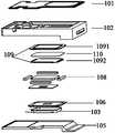
- Fig. 1is an exploded view of the structure of the sound generating device of the present invention.
- Fig. 2is a schematic diagram of the structure of the sound generating device of the present invention.
- Fig. 3is a cross-sectional view of A-A shown in Fig. 2 of the present invention.
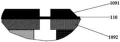
- Fig. 4is a partial enlarged view of the sound generating device of the present invention.
- a sound generating deviceis provided. 1 to 4, the sound generating device includes:
- a housingthe housing has an accommodating space, and a voice coil 107 and a magnetic circuit system are arranged in the accommodating space;
- the magnetic circuit systemincludes two magnetically conductive yokes 109 and a magnet 108 arranged on the magnetically conductive yoke 109; in this example, the magnet assembly 108 is arranged on the magnetically conductive yoke 109.
- the magnetic circuit systemincludes a first magnetic yoke 1091 and a second magnetic yoke 1092.
- the first magnetic yoke 1091 and the second magnetic yoke 1092are arranged in parallel in the vertical direction; specifically, the first magnetic yoke 1091 and the second magnetic yoke 1092 are arranged in parallel in the vertical direction;
- a magnetically conductive yoke 1091 and a second magnetically conductive yoke 1092are arranged in parallel along the vibration direction of the diaphragm 106, and the first magnetically conductive yoke 1091 is farther away from the voice coil 107 than the second magnetically conductive yoke 1092.
- a waterproof and air-permeable component 110is arranged between the first magnetic yoke 1091 and the second magnetic yoke 1092.
- the waterproof and air-permeable member 110may be provided at a local position between the first magnetic yoke 1091 and the second magnetic yoke 1092.
- the waterproof and air-permeable member 110is used to cover the first magnetic yoke 1091 and the second magnetic yoke, respectively.
- the waterproof and breathable part 110can be sandwiched between the first magnetic yoke 1091 and the second magnetic yoke 1092, wherein the length of the waterproof and breathable part 110 is the same as the length of the magnetic yoke to cover the first A yoke 1091 and a second yoke 1092 are respectively provided with heat dissipation holes.
- the magnetic yoke 109is used to fix the magnet assembly 108; on the other hand, it is used to constrain the magnetic lines of induction generated by the magnetic circuit assembly to prevent magnetic leakage, improve the magnetic induction effect of the sound device, and thereby improve the acoustic performance of the sound device.
- the voice coil 109is placed in the magnetic gap B formed by the magnet assembly 108;
- the magnetic yoke 109is provided with a heat dissipation hole A, and the heat dissipation hole A communicates with the magnetic gap B;
- the heat dissipation hole Ais configured to be capable of dissipating heat generated inside the sound emitting device.
- a heat dissipation hole Ais provided on the magnetic yoke 109 to make the rear acoustic cavity of the sounding device communicate with the outside of the sounding device. Therefore, the heat generated after the voice coil 107 in the magnetic gap is connected to the electrical signal can pass through the magnetic gap and dissipate heat. The holes are conducted to the outside of the sounding device, which improves the heat dissipation efficiency of the sounding device.
- the heat dissipation holes on the two magnetic yokesare preferably arranged correspondingly.
- a more preferred solutionis that the heat dissipation holes on the two magnetic yokes are arranged directly opposite to the magnetic gap. This is convenient to ensure that the heat generated by the voice coil can be better discharged through the heat dissipation hole.
- the area of the heat dissipation hole on the first magnetic yoke 1091is larger than the area of the heat dissipation hole on the second magnetic yoke 1092.
- the first magnetic yoke 1091is provided with a first heat dissipation hole
- the second magnetic yoke 1092is provided with a second heat dissipation hole; wherein, the area of the first heat dissipation hole is larger than the area of the second heat dissipation hole.
- the installation process of the sound devicefirst install the magnetic yoke 1092 that is relatively closer to the voice coil; after installing and fixing the magnetic yoke 1092 that is close to the voice coil 107, install the magnetic yoke that is relatively farther away from the voice coil 107 1091;
- the area of the first magnetic yoke 1091 for the heat dissipation holesis larger than the area of the second magnetic yoke 1092 for the heat dissipation holes in this example.
- the heat generated inside the sound deviceis discharged in time through the magnetic gap and the heat dissipation hole.
- the first magnetic yoke 1091 and the second magnetic yoke 1092can be arranged in structures with unequal thicknesses.
- the thickness of the first magnetic yoke 1091is greater than the thickness of the second magnetic yoke 1092
- the inner second magnetic yoke 1092is set as a thinner sheet, which can increase the available space inside.
- four heat dissipation holesare respectively provided near the edge of the magnetic yoke; or an annular groove is formed on the magnetic yoke, and the annular groove is the heat dissipation hole.
- four heat dissipation holesare respectively arranged near the edge of the two magnetic yokes.
- the four heat dissipation holes on each magnetic yokeare not connected to each other, but are connected to the four heat dissipation holes on the other magnetic yoke. There is a one-to-one correspondence, and the four heat dissipation holes respectively communicate with the magnetic gap, and the four heat dissipation holes play the role of dissipating heat inside the sound device.
- annular grooveis formed in the magnetic yoke, that is, the four heat dissipation holes communicate with each other so that the annular groove has a racetrack-like structure.
- the second magnetic yoke 1092is provided with four heat dissipation holes that are not connected to each other, and the first magnetic yoke 1091 is provided with an annular groove communicating with each other; during the installation process, the position of the annular groove can be connected to the four not communicating with each other.
- the heat dissipation holesare adapted so that the heat dissipation holes provided on the first magnetic yoke 1091 and the second magnetic yoke 1092 communicate with each other.
- the magnet assembly 108includes a center magnet and a side magnet, and the center magnet and the side magnets form the magnetic gap.
- the magnetic circuit assemblyincludes side magnets 1082 and center magnets 1081.
- the center magnet 1081 and the side magnet 1082are both arranged on the magnetic yoke 109, the side magnet 1081 surrounds the center magnet 1081, and the side magnet 1082 and the center magnet 1081 are located on the same plane.
- the magnetic gapis formed between the center magnet 1081 and the side magnets 1082.
- the sound emitting deviceincludes a diaphragm 107, and the diaphragm 107 divides the accommodating space into a front acoustic cavity C and a rear acoustic cavity;
- the voice coil 107 and the magnetic circuit systemare both arranged in the rear acoustic cavity. Therefore, the magnetic gap B formed by the magnetic circuit assembly in this example and the heat dissipation hole A opened by the magnetic yoke 109 are both located in the back acoustic cavity; compared with the sound device in the prior art, the back acoustic cavity is a closed cavity, this example uses the magnetic gap B And the heat dissipation hole A can discharge the heat generated by the voice coil 107 and the heat located around the voice coil 107 to the outside of the sound generating device through the magnetic gap and the heat dissipation hole.
- the waterproof and breathable member 110may be made of a porous material with waterproof function and breathability, which itself can form a channel for air circulation, but can prevent liquid from entering the inner cavity of the sound device.
- the housingincludes an upper housing 101 and a lower housing 103; the upper housing 101 and the lower housing 103 are enclosed to form the accommodating space; the magnetic circuit system is clamped in the lower housing 103 on.
- the lower surface of the lower shell 103is a non-closed structure, that is, is provided with a hollow mounting part.
- the housingincludes a middle shell 102, and the middle shell 102 is provided with a pressure relief hole; the pressure relief hole is configured to balance the air pressure of the front acoustic cavity and the rear acoustic cavity.
- the middle shell 102is opened at both ends along the vibration direction of the diaphragm, and the upper shell 101 and the lower shell 103 can be covered on the middle shell 102.
- the middle shell 102is provided with a pressure relief hole; on the one hand, the pressure relief hole is configured to balance the air pressure of the front acoustic cavity and the rear acoustic cavity; on the other hand, the middle shell is located in the rear acoustic cavity of the sound device, and the pressure is generated in the rear acoustic cavity.
- the heatcan be conducted to the heat dissipation hole of the magnetic yoke through the pressure relief hole, so as to discharge the heat to the outside of the sound generating device.
- a metal layer 1061is provided on the diaphragm 106, and the voice coil 107 is fixedly connected to the metal layer 1061; a steel sheet 105 is embedded on the shell; The layer 1061 is fixedly connected to the steel sheet 105 through the heat conducting element 104.
- an openingis formed on the outer surface of the housing, and the steel sheet 105 is embedded in the opening.
- the position of the shell corresponding to the diaphragm 106is provided with the steel sheet 105.
- the steel sheet 105on the one hand ensures the rigidity of the shell and reduces the thickness of the shell; on the other hand, it can increase the internal cavity space of the shell and improve the performance of the sound generating device. Acoustic performance; as shown in FIG. 3, in this example, a steel sheet 105 is provided at the position of the upper shell 101 corresponding to the diaphragm 106.
- a metal layer 1061is provided on the surface of the diaphragm 106, wherein the metal layer 1061 has thermal conductivity; at the same time, the diaphragm 106 is connected to the steel sheet 105 through the heat conductive member 104, so the voice coil 107 is connected to the steel sheet through the metal layer and the heat conductive member.
- the voice coil 107receives an electrical signal, the voice coil 107 will generate heat.
- the metal layer, the heat-conducting member and the steel sheetwill conduct the generated heat to the outside of the sound generating device to avoid heat accumulation in the sound generating device and affect the heat dissipation efficiency.
- the inventioncan improve the heat dissipation efficiency of the sound generating device, solves the problems of the vibration of the diaphragm that the vibration of the diaphragm is easily shifted and the diaphragm folds caused by the unbalanced air pressure of the front and rear sound chambers in the prior art, optimizes the parameter performance of the sound device and improves the sound generation The acoustic performance of the device.
- the shape of the heat dissipation holeincludes any one of a circle, an ellipse, and a rectangle.
- the heat dissipation holes provided in the magnetic yokecorrespond to the magnetic gaps one by one.
- the heat dissipation holesare uniformly distributed on the magnetic yoke in an array.
- an electronic terminalincludes the above-mentioned sound emitting device.
- the sound emitting deviceWhen the sound emitting device is applied to an electronic terminal, the heat dissipation efficiency of the electronic terminal can be improved, and the electronic terminal can be prevented from easily generating heat when the electronic terminal is used for a long time, and affecting its service life.
Landscapes
- Physics & Mathematics (AREA)
- Engineering & Computer Science (AREA)
- Acoustics & Sound (AREA)
- Signal Processing (AREA)
- Audible-Bandwidth Dynamoelectric Transducers Other Than Pickups (AREA)
Abstract
Description
Translated fromChinese本发明涉及电声转换技术领域,具体地涉及一种发声装置以及电子终端。The present invention relates to the technical field of electro-acoustic conversion, in particular to a sound generating device and an electronic terminal.
发声装置是实现电声转换的基本单元。由于发声装置的音圈是由导线绕制而成,因此,音圈在接收到交流电信号时便会产生热量,工作时间越长,发热越明显,如果音圈长时间发热无法有效散热,则将影响发声装置的使用寿命及所能提供的最大音量。The sound device is the basic unit to realize the electro-acoustic conversion. Since the voice coil of the sound device is wound by a wire, the voice coil will generate heat when it receives an alternating current signal. The longer the working time, the more obvious the heat will be. If the voice coil heats up for a long time and cannot effectively dissipate heat, then Will affect the service life of the sound device and the maximum volume that can be provided.
在现有技术中,音圈和磁路组件均被安装在发声装置的后声腔中,且后声腔为密闭结构,这使得音圈散热一直都是业界难以解决的问题,而且,随着设置发声装置的电子设备的集成度越来越高,发声装置的尺寸也越来越小,音圈发热对发声装置性能的影响就尤为突出,因此,非常有必要提供一种新的发声装置结构以有利于音圈散热。In the prior art, both the voice coil and the magnetic circuit components are installed in the rear acoustic cavity of the sound generating device, and the rear acoustic cavity is a closed structure. This makes the heat dissipation of the voice coil a problem that the industry has always been difficult to solve. The integration of the electronic equipment of the device is getting higher and higher, and the size of the sounding device is getting smaller and smaller. The heating of the voice coil has a particularly prominent influence on the performance of the sounding device. Therefore, it is very necessary to provide a new sounding device structure to have Conducive to voice coil heat dissipation.
发明内容Summary of the invention
本发明的一个目的是提供发声装置的新的技术方案,以在基本不影响原有声学性能的情况下实现音圈散热。An object of the present invention is to provide a new technical solution for the sound generating device, so as to realize the heat dissipation of the voice coil without substantially affecting the original acoustic performance.
根据本发明的第一方面,提供一种发声装置。所述发声装置包括:According to the first aspect of the present invention, a sound generating device is provided. The sound generating device includes:
壳体,所述壳体具有容置空间,所述容置空间内安装有音圈和磁路系统;A housing, the housing has an accommodating space, and a voice coil and a magnetic circuit system are installed in the accommodating space;
所述磁路系统中形成有磁间隙,所述音圈的一端置于所述磁间隙内;A magnetic gap is formed in the magnetic circuit system, and one end of the voice coil is placed in the magnetic gap;
所述磁路系统包括在竖直方向上叠设的两个导磁轭;两个所述导磁轭上分别开设散热孔,所述散热孔与所述磁间隙相连通,所述散热孔配置为能够将发声装置内部产生的热量排出;The magnetic circuit system includes two magnetic yokes stacked in a vertical direction; two of the magnetic yokes are respectively provided with heat dissipation holes, the heat dissipation holes communicate with the magnetic gap, and the heat dissipation holes are configured To be able to dissipate the heat generated inside the sound device;
两个所述导磁轭之间还设置有防水透气部件,所述防水透气部件覆盖 所述散热孔。A waterproof and air-permeable component is also arranged between the two magnetic yokes, and the waterproof and air-permeable component covers the heat dissipation hole.
可选地,两个所述导磁轭分别为第一导磁轭和第二导磁轭;所述第一导磁轭相对所述第二导磁轭远离所述音圈。Optionally, the two magnetic conductive yokes are respectively a first magnetic conductive yoke and a second magnetic conductive yoke; the first magnetic conductive yoke is far away from the voice coil relative to the second magnetic conductive yoke.
可选地,所述第一导磁轭上的所述散热孔与所述第二导磁轭上的所述散热孔对应设置,且位于所述第一导磁轭上的所述散热孔的面积不小于所述第二导磁轭上的所述散热孔的面积;和/或,Optionally, the heat dissipation holes on the first magnetic yoke are arranged correspondingly to the heat dissipation holes on the second magnetic yoke, and the heat dissipation holes are located on the first magnetic yoke. The area is not less than the area of the heat dissipation hole on the second magnetic yoke; and/or,
所述第一导磁轭、所述第二导磁轭在竖直方向上的厚度不等。The thickness of the first magnetic yoke and the second magnetic yoke in the vertical direction are different.
可选地,靠近所述导磁轭的边缘位置分别设置有四个所述散热孔;Optionally, four heat dissipation holes are respectively provided near the edge of the magnetic yoke;
或者在所述导磁轭上形成环形槽,所述环形槽为所述散热孔。Alternatively, an annular groove is formed on the magnetic yoke, and the annular groove is the heat dissipation hole.
可选地,所述散热孔的形状包括圆形、椭圆形、矩形中的任意一种。Optionally, the shape of the heat dissipation hole includes any one of a circle, an ellipse, and a rectangle.
可选地,所述导磁轭上安装有中心磁铁和边磁铁,所述中心磁铁与边磁铁形成环形的所述磁间隙。Optionally, a center magnet and a side magnet are installed on the magnetic yoke, and the center magnet and the side magnets form the annular magnetic gap.
可选地,所述壳体包括上壳和下壳;所述上壳和下壳围合形成所述容置空间;Optionally, the housing includes an upper housing and a lower housing; the upper housing and the lower housing enclose the housing space;
所述下壳的底面设置有镂空的安装部,所述磁路系统卡设在所述下壳上的安装部上。A hollow mounting part is provided on the bottom surface of the lower shell, and the magnetic circuit system is clamped on the mounting part on the lower shell.
可选地,所述发声装置包括振膜,所述振膜将所述容置空间分隔成前声腔和后声腔;所述音圈和磁路系统均设置在所述后声腔内。Optionally, the sound emitting device includes a vibrating membrane that separates the accommodating space into a front acoustic cavity and a rear acoustic cavity; the voice coil and the magnetic circuit system are both arranged in the rear acoustic cavity.
可选地,所述发声装置还包括振膜;Optionally, the sound emitting device further includes a diaphragm;
所述振膜上设置有金属层,所述音圈与所述金属层固定连接;A metal layer is provided on the diaphragm, and the voice coil is fixedly connected to the metal layer;
所述壳体上嵌设有钢片;所述金属层分别与所述音圈和钢片固定连接。A steel sheet is embedded on the shell; the metal layer is fixedly connected with the voice coil and the steel sheet, respectively.
根据本发明另一方面,提供一种电子终端。所述电子终端包括上述所述的发声装置。According to another aspect of the present invention, an electronic terminal is provided. The electronic terminal includes the above-mentioned sound emitting device.
本发明的有益效果:本发明发声装置的两个导磁轭开设散热孔,所述散热孔与所述磁间隙相连通;所述散热孔能够将发声装置内部产生的热量排出至发声装置的外部,进而能够快速降低音圈的温度。The beneficial effects of the present invention: the two magnetic yokes of the sound device of the present invention are provided with heat dissipation holes, and the heat dissipation holes communicate with the magnetic gap; the heat dissipation holes can discharge the heat generated inside the sound device to the outside of the sound device , Which in turn can quickly reduce the temperature of the voice coil.
通过以下参照附图对本发明的示例性实施例的详细描述,本发明的其它特征及其优点将会变得清楚。Through the following detailed description of exemplary embodiments of the present invention with reference to the accompanying drawings, other features and advantages of the present invention will become clear.
被结合在说明书中并构成说明书的一部分的附图示出了本发明的实施例,并且连同其说明一起用于解释本发明的原理。The drawings incorporated in the specification and constituting a part of the specification illustrate the embodiments of the present invention, and together with the description are used to explain the principle of the present invention.
图1所示为本发明发声装置的结构分解图。Fig. 1 is an exploded view of the structure of the sound generating device of the present invention.
图2所示为本发明发声装置的结构示意图。Fig. 2 is a schematic diagram of the structure of the sound generating device of the present invention.
图3所示为本发明图2所示的A-A剖视图。Fig. 3 is a cross-sectional view of A-A shown in Fig. 2 of the present invention.
图4所示为本发明发声装置的局部放大图。Fig. 4 is a partial enlarged view of the sound generating device of the present invention.
现在将参照附图来详细描述本发明的各种示例性实施例。应注意到:除非另外具体说明,否则在这些实施例中阐述的部件和步骤的相对布置、数字表达式和数值不限制本发明的范围。Various exemplary embodiments of the present invention will now be described in detail with reference to the accompanying drawings. It should be noted that unless specifically stated otherwise, the relative arrangement of components and steps, numerical expressions and numerical values set forth in these embodiments do not limit the scope of the present invention.
以下对至少一个示例性实施例的描述实际上仅仅是说明性的,决不作为对本发明及其应用或使用的任何限制。The following description of at least one exemplary embodiment is actually only illustrative, and in no way serves as any limitation to the present invention and its application or use.
对于相关领域普通技术人员已知的技术、方法和设备可能不作详细讨论,但在适当情况下,所述技术、方法和设备应当被视为说明书的一部分。The technologies, methods, and equipment known to those of ordinary skill in the relevant fields may not be discussed in detail, but where appropriate, the technologies, methods, and equipment should be regarded as part of the specification.
在这里示出和讨论的所有例子中,任何具体值应被解释为仅仅是示例性的,而不是作为限制。因此,示例性实施例的其它例子可以具有不同的值。In all examples shown and discussed herein, any specific value should be interpreted as merely exemplary, rather than as a limitation. Therefore, other examples of the exemplary embodiment may have different values.
应注意到:相似的标号和字母在下面的附图中表示类似项,因此,一旦某一项在一个附图中被定义,则在随后的附图中不需要对其进行进一步讨论。It should be noted that similar reference numerals and letters indicate similar items in the following drawings, therefore, once an item is defined in one drawing, it does not need to be further discussed in the subsequent drawings.
根据本发明的一个实施例,提供一种发声装置。参照图1~图4,所述发声装置包括:According to an embodiment of the present invention, a sound generating device is provided. 1 to 4, the sound generating device includes:
壳体,所述壳体具有容置空间,所述容置空间内设置有音圈107和磁路系统;A housing, the housing has an accommodating space, and a
所述磁路系统包括两个导磁轭109和设置在所述导磁轭109上的磁铁108;本例子中所述磁铁组件108设置在所述导磁轭109上。The magnetic circuit system includes two magnetically
具体地,所述磁路系统包括第一导磁轭1091和第二导磁轭1092,所 述第一导磁轭1091和第二导磁轭1092在竖直方向上平行设置;具体地,第一导磁轭1091和第二导磁轭1092沿振膜106的振动方向平行设置,并且第一导磁轭1091相对于第二导磁轭1092而言,更加远离音圈107。所述第一导磁轭1091与第二导磁轭1092之间设置有防水透气部件110。例如可以在第一导磁轭1091和第二导磁轭1092之间的局部位置设置所述防水透气部件110,例如防水透气部件110用于覆盖第一导磁轭1091和第二导磁轭分别开设的散热孔;或者可以在第一导磁轭1091和第二导磁轭1092之间夹设所述防水透气部件110,其中防水透气部件110的长度与导磁轭的长度一致,以覆盖第一导磁轭1091和第二导磁轭1092分别开设的散热孔。Specifically, the magnetic circuit system includes a first
导磁轭109一方面用于固定所述磁铁组件108;另一方面用于约束磁路组件产生的磁感线防止漏磁,提高发声装置的磁感效应,进而提高发声装置的声学性能。On the one hand, the
所述音圈109置于磁铁组件108形成的磁间隙B中;The
所述导磁轭109开设散热孔A,所述散热孔A与所述磁间隙B相连通;The
所述散热孔A配置为能够将发声装置内部产生的热量排出。The heat dissipation hole A is configured to be capable of dissipating heat generated inside the sound emitting device.
本例子通过在导磁轭109上开设散热孔A使得发声装置的后声腔与发声装置的外部相互连通,因此位于磁间隙内的音圈107通入电信号后产生的热量能够通过磁间隙和散热孔传导至发声装置的外部,提高发声装置的散热效率。In this example, a heat dissipation hole A is provided on the
在一个可选地实施例中,位于两个导磁轭上的散热孔优选为对应设置,当然,更为优选的方案是,两个导磁轭上的散热孔正对磁间隙设置。这样便于保证音圈产生的热量能够更好的通过散热孔排出。In an optional embodiment, the heat dissipation holes on the two magnetic yokes are preferably arranged correspondingly. Of course, a more preferred solution is that the heat dissipation holes on the two magnetic yokes are arranged directly opposite to the magnetic gap. This is convenient to ensure that the heat generated by the voice coil can be better discharged through the heat dissipation hole.
可选地,位于第一导磁轭1091上的散热孔的面积大于第二导磁轭1092上的散热孔的面积。Optionally, the area of the heat dissipation hole on the first
具体地,第一导磁轭1091开设第一散热孔,第二导磁轭1092开设第二散热孔;其中,第一散热孔的面积大于第二散热孔的面积。例如在发声 装置的安装过程中,首先安装相对更靠近音圈的导磁轭1092;当把靠近音圈107的导磁轭1092安装固定好之后,再安装相对更加远离音圈107的导磁轭1091;为了克服由于安装误差导致开设的两个散热孔在结构上不能够相互连通时,本例子将第一导磁轭1091开设散热孔的面积大于第二导磁轭1092开设散热孔的面积,以避免这一结构误差,使得发声装置内部产生的热量通过磁间隙和散热孔及时排出。Specifically, the first
在一个可选的实施例中,第一导磁轭1091和第二导磁轭1092可以设置为厚度不等的结构,优选为第一导磁轭1091的厚度大于第二导磁轭1092的厚度,一方面能够保证导磁轭109的整体结构强度,另一方面内侧的第二导磁轭1092设置为厚度更薄的薄片,可以增大内部的可利用空间。In an optional embodiment, the first
在一个可选地实施例中,靠近所述导磁轭的边缘分别设置有四个所述散热孔;或者在所述导磁轭上形成环形槽,所述环形槽为所述散热孔。例如在靠近两个导磁轭的边缘位置分别设置四个散热孔,位于每一个导磁轭上的四个散热孔之间互不连通,但与位于另一个导磁轭上的四个散热孔可一一对应,其四个散热孔分别与磁间隙相通,四个散热孔起到将发声装置内部的热量排出的作用。In an optional embodiment, four heat dissipation holes are respectively provided near the edge of the magnetic yoke; or an annular groove is formed on the magnetic yoke, and the annular groove is the heat dissipation hole. For example, four heat dissipation holes are respectively arranged near the edge of the two magnetic yokes. The four heat dissipation holes on each magnetic yoke are not connected to each other, but are connected to the four heat dissipation holes on the other magnetic yoke. There is a one-to-one correspondence, and the four heat dissipation holes respectively communicate with the magnetic gap, and the four heat dissipation holes play the role of dissipating heat inside the sound device.
或者在导磁轭形成环形槽,即四个散热孔相互连通使得环形槽呈类跑道结构。Or an annular groove is formed in the magnetic yoke, that is, the four heat dissipation holes communicate with each other so that the annular groove has a racetrack-like structure.
可选地,第二导磁轭1092设置互相不连通的四个散热孔,第一导磁轭1091设置相互连通的环形槽;在安装过程中,环形槽的位置可以与互相不连通的四个散热孔适应,使得第一导磁轭1091和第二导磁轭1092上开设的散热孔相互连通。Optionally, the second
在一个可选地实施例中,所述磁铁组件108包括中心磁铁和边磁铁,所述中心磁铁与边磁铁形成所述磁间隙。例如所述磁路组件包括边磁铁1082、中心磁铁1081。所述中心磁铁1081和边磁铁1082均设置在导磁轭109上,所述边磁铁1081围绕所述中心磁铁1081周围,其中边磁铁1082和中心磁铁1081位于同一平面上。所述磁间隙形成在所述中心磁铁1081和边磁铁1082之间。In an optional embodiment, the
在一个可选地实施例中,所述发声装置包括振膜107,所述振膜107将所述容置空间分隔成前声腔C和后声腔;In an optional embodiment, the sound emitting device includes a
所述音圈107和磁路系统均设置在所述后声腔内。因此本例子磁路组件形成的磁间隙B和导磁轭109开设的散热孔A均位于后声腔中;与现有技术中发声装置的后声腔为封闭腔体相比,本例子通过磁间隙B和散热孔A能够将音圈107产生的热量和位于音圈107周围的热量通过磁间隙和散热孔排出至发声装置的外部。The
另外需要说明的是,本实施例中,防水透气部件110可以采用具有防水功能且可以透气的多孔性材质,其自身可以形成气流流通的通道,但可以阻止液体进入发声装置的内腔之中。In addition, it should be noted that, in this embodiment, the waterproof and
在一个可选地实施例中,壳体包括上壳101和下壳103;所述上壳101和下壳103围合形成所述容置空间;所述磁路系统卡设在所述下壳103上。例如所述下壳103的下表面为非封闭结构,即设置有镂空的安装部,当磁路系统卡设在下壳103上时,导磁轭109直接与外部环境相通,因此导磁轭109开设的散热孔直接与外部环境相互连通,当音圈通入电信号产生的热量能够通过所述散热孔排出至发声装置的外部。In an optional embodiment, the housing includes an
在一个可选地实施例中,所述壳体包括中壳102,所述中壳102开设有泄压孔;所述泄压孔配置为平衡前声腔和后声腔的气压。例如所述中壳102沿振膜的振动方向呈两端敞口设置,上壳101和下壳103可以盖合在所述中壳102上。所述中壳102的内部开设泄压孔;一方面所述泄压孔配置为平衡前声腔和后声腔的气压;另一方面所述中壳位于发声装置的后声腔内,后声腔内产生的热量通过所述泄压孔可以传导至导磁轭的散热孔处,以将热量排出至发声装置的外部。In an optional embodiment, the housing includes a
在一个可选地实施例中,所述振膜106上设置有金属层1061,所述音圈107与所述金属层1061固定连接;所述壳体上嵌设有钢片105;所述金属层1061通过导热件104与钢片105固定连接。In an optional embodiment, a
例如,在壳体的外表面形成有开口,所述钢片105嵌设在所述开口处。 其中壳体对应振膜106的位置设置有所述钢片105,所述钢片105一方面保证壳体刚性,降低壳体厚度;另一方面能够增加壳体内部腔体空间,提高发声装置的声学性能;如图3所示,本例子在上壳101对应振膜106的位置设置有钢片105。For example, an opening is formed on the outer surface of the housing, and the
本例子在振膜106的表面设置金属层1061,其中金属层1061具有导热性能;同时振膜106通过导热件104与钢片105连接,因此音圈107通过金属层和导热件与钢片连接。当音圈107通入电信号后,音圈107会产生热量,其中金属层,导热件和钢片会将产生的热量传导至发声装置的外部,避免发声装置内热量聚集,影响散热效率。本发明能够提高发声装置的散热效率,解决了现有技术中因前后声腔气压不平衡,引起的振膜振动容易发生偏移和振膜褶皱的问题,优化了发声装置的参数性能以及提高了发声装置的声学性能。In this example, a
在一个可选地实施例中,所述散热孔的形状包括圆形,椭圆形,矩形中的任意一种。当边磁铁1082环绕中心磁铁1081的周围呈阵列方式排布形成多个磁间隙时,设置在导磁轭的散热孔一一与磁间隙相对应。例如所述散热孔呈阵列方式均匀分布在导磁轭上。In an optional embodiment, the shape of the heat dissipation hole includes any one of a circle, an ellipse, and a rectangle. When the
根据本发明另一方面,提供一种电子终端。所述电子终端包括上述所述的发声装置。当所述发声装置应用到电子终端时,能够提高电子终端的散热效率,避免电子终端使用时间过长时容易发热,影响其使用寿命。According to another aspect of the present invention, an electronic terminal is provided. The electronic terminal includes the above-mentioned sound emitting device. When the sound emitting device is applied to an electronic terminal, the heat dissipation efficiency of the electronic terminal can be improved, and the electronic terminal can be prevented from easily generating heat when the electronic terminal is used for a long time, and affecting its service life.
虽然已经通过例子对本发明的一些特定实施例进行了详细说明,但是本领域的技术人员应该理解,以上例子仅是为了进行说明,而不是为了限制本发明的范围。本领域的技术人员应该理解,可在不脱离本发明的范围和精神的情况下,对以上实施例进行修改。本发明的范围由所附权利要求来限定。Although some specific embodiments of the present invention have been described in detail through examples, those skilled in the art should understand that the above examples are only for illustration and not for limiting the scope of the present invention. Those skilled in the art should understand that the above embodiments can be modified without departing from the scope and spirit of the present invention. The scope of the invention is defined by the appended claims.
Claims (10)
Translated fromChineseApplications Claiming Priority (2)
| Application Number | Priority Date | Filing Date | Title |
|---|---|---|---|
| CN201911310963.0ACN111107468B (en) | 2019-12-18 | 2019-12-18 | Sound production device and electronic terminal |
| CN201911310963.0 | 2019-12-18 |
Publications (1)
| Publication Number | Publication Date |
|---|---|
| WO2021120286A1true WO2021120286A1 (en) | 2021-06-24 |
Family
ID=70422202
Family Applications (1)
| Application Number | Title | Priority Date | Filing Date |
|---|---|---|---|
| PCT/CN2019/128997CeasedWO2021120286A1 (en) | 2019-12-18 | 2019-12-27 | Sounding device and electronic terminal |
Country Status (2)
| Country | Link |
|---|---|
| CN (1) | CN111107468B (en) |
| WO (1) | WO2021120286A1 (en) |
Families Citing this family (1)
| Publication number | Priority date | Publication date | Assignee | Title |
|---|---|---|---|---|
| CN114866924B (en)* | 2022-05-07 | 2024-07-30 | 歌尔股份有限公司 | Sound generating device and electronic terminal |
Citations (7)
| Publication number | Priority date | Publication date | Assignee | Title |
|---|---|---|---|---|
| CN201608873U (en)* | 2009-12-14 | 2010-10-13 | 常州美欧电子有限公司 | Electroacoustic Energy Sound Device |
| CN102905214A (en)* | 2011-07-25 | 2013-01-30 | 张凡 | Driver of double-magnet double-magnetic-gap double-coil transducer |
| KR20140098465A (en)* | 2013-01-31 | 2014-08-08 | 주식회사 이엠텍 | Heat dissipation structure of microspeaker |
| CN206472300U (en)* | 2016-12-29 | 2017-09-05 | 奥音科技(北京)有限公司 | A kind of magnetic circuit system and Microspeaker |
| CN207354604U (en)* | 2017-09-28 | 2018-05-11 | 瑞声科技(新加坡)有限公司 | Loudspeaker |
| CN108566598A (en)* | 2018-04-24 | 2018-09-21 | 歌尔股份有限公司 | A kind of sound-producing device |
| CN208638592U (en)* | 2018-08-01 | 2019-03-22 | 瑞声科技(新加坡)有限公司 | Microphone device |
Family Cites Families (7)
| Publication number | Priority date | Publication date | Assignee | Title |
|---|---|---|---|---|
| US7907742B2 (en)* | 2003-10-31 | 2011-03-15 | Fujitsu Ten Limited | Exciter for directly vibrating board and speaker apparatus used the same |
| CN204291370U (en)* | 2014-12-16 | 2015-04-22 | 歌尔声学股份有限公司 | Microspeaker |
| CN204707270U (en)* | 2015-06-23 | 2015-10-14 | 歌尔声学股份有限公司 | Loud speaker |
| CN205142508U (en)* | 2015-10-28 | 2016-04-06 | 瑞声光电科技(常州)有限公司 | Loudspeaker box |
| CN106028234B (en)* | 2016-05-31 | 2021-08-31 | 歌尔股份有限公司 | Vibrating diaphragm and loudspeaker monomer |
| CN206212266U (en)* | 2016-11-24 | 2017-05-31 | 广州飞达音响股份有限公司 | A kind of supersound projector |
| CN109218928B (en)* | 2018-01-10 | 2024-01-30 | 歌尔股份有限公司 | Sounding device |
- 2019
- 2019-12-18CNCN201911310963.0Apatent/CN111107468B/enactiveActive
- 2019-12-27WOPCT/CN2019/128997patent/WO2021120286A1/ennot_activeCeased
Patent Citations (7)
| Publication number | Priority date | Publication date | Assignee | Title |
|---|---|---|---|---|
| CN201608873U (en)* | 2009-12-14 | 2010-10-13 | 常州美欧电子有限公司 | Electroacoustic Energy Sound Device |
| CN102905214A (en)* | 2011-07-25 | 2013-01-30 | 张凡 | Driver of double-magnet double-magnetic-gap double-coil transducer |
| KR20140098465A (en)* | 2013-01-31 | 2014-08-08 | 주식회사 이엠텍 | Heat dissipation structure of microspeaker |
| CN206472300U (en)* | 2016-12-29 | 2017-09-05 | 奥音科技(北京)有限公司 | A kind of magnetic circuit system and Microspeaker |
| CN207354604U (en)* | 2017-09-28 | 2018-05-11 | 瑞声科技(新加坡)有限公司 | Loudspeaker |
| CN108566598A (en)* | 2018-04-24 | 2018-09-21 | 歌尔股份有限公司 | A kind of sound-producing device |
| CN208638592U (en)* | 2018-08-01 | 2019-03-22 | 瑞声科技(新加坡)有限公司 | Microphone device |
Also Published As
| Publication number | Publication date |
|---|---|
| CN111107468A (en) | 2020-05-05 |
| CN111107468B (en) | 2021-02-19 |
Similar Documents
| Publication | Publication Date | Title |
|---|---|---|
| CN101601308B (en) | Speaker Motors and Speakers | |
| WO2016197569A1 (en) | Loudspeaker module | |
| CN104205870B (en) | Device for reproducing an acoustic signal and method for cooling a loudspeaker | |
| US20140270269A1 (en) | Loudspeaker device | |
| TWM499720U (en) | Piezoelectric ceramic dual-band earphone structure | |
| WO2016176996A1 (en) | Loudspeaker module | |
| WO2019218593A1 (en) | Acoustic generator and earphone | |
| WO2016197535A1 (en) | Speaker device | |
| WO2021120948A1 (en) | Loudspeaker module and electronic device | |
| WO2021120950A1 (en) | Loudspeaker module and electronic device | |
| CN115065917B (en) | Sounding device and terminal equipment | |
| WO2021120286A1 (en) | Sounding device and electronic terminal | |
| WO2021120287A1 (en) | Sound production apparatus and electronic terminal | |
| CN106028234B (en) | Vibrating diaphragm and loudspeaker monomer | |
| KR100692256B1 (en) | Heat dissipation structure of micro speaker | |
| JP2016010019A (en) | Speaker device | |
| CN115297411A (en) | speaker | |
| CN112788498B (en) | A sound generating device and an electronic terminal | |
| CN208158874U (en) | Loudspeaker arrangement | |
| CN217037451U (en) | Basin frame assembly, loudspeaker and sound production equipment | |
| CN215601459U (en) | A loudspeaker and sound box | |
| CN221930102U (en) | A diaphragm assembly of a loudspeaker | |
| CN221960586U (en) | An outdoor alarm suitable for high voltage, high current and high sound pressure | |
| CN116320916B (en) | Transduction driver | |
| KR20140146744A (en) | Bobbin for speaker device and speaker device using same |
Legal Events
| Date | Code | Title | Description |
|---|---|---|---|
| 121 | Ep: the epo has been informed by wipo that ep was designated in this application | Ref document number:19956876 Country of ref document:EP Kind code of ref document:A1 | |
| NENP | Non-entry into the national phase | Ref country code:DE | |
| 122 | Ep: pct application non-entry in european phase | Ref document number:19956876 Country of ref document:EP Kind code of ref document:A1 |