WO2021112357A1 - Body fluid observation device - Google Patents
Body fluid observation deviceDownload PDFInfo
- Publication number
- WO2021112357A1 WO2021112357A1PCT/KR2020/007650KR2020007650WWO2021112357A1WO 2021112357 A1WO2021112357 A1WO 2021112357A1KR 2020007650 WKR2020007650 WKR 2020007650WWO 2021112357 A1WO2021112357 A1WO 2021112357A1
- Authority
- WO
- WIPO (PCT)
- Prior art keywords
- chamber
- horizontal direction
- body fluid
- light source
- substrate
- Prior art date
- Legal status (The legal status is an assumption and is not a legal conclusion. Google has not performed a legal analysis and makes no representation as to the accuracy of the status listed.)
- Ceased
Links
Images


Classifications
- A—HUMAN NECESSITIES
- A61—MEDICAL OR VETERINARY SCIENCE; HYGIENE
- A61B—DIAGNOSIS; SURGERY; IDENTIFICATION
- A61B5/00—Measuring for diagnostic purposes; Identification of persons
- A61B5/145—Measuring characteristics of blood in vivo, e.g. gas concentration or pH-value ; Measuring characteristics of body fluids or tissues, e.g. interstitial fluid or cerebral tissue
- A61B5/14507—Measuring characteristics of blood in vivo, e.g. gas concentration or pH-value ; Measuring characteristics of body fluids or tissues, e.g. interstitial fluid or cerebral tissue specially adapted for measuring characteristics of body fluids other than blood
- A—HUMAN NECESSITIES
- A61—MEDICAL OR VETERINARY SCIENCE; HYGIENE
- A61B—DIAGNOSIS; SURGERY; IDENTIFICATION
- A61B10/00—Instruments for taking body samples for diagnostic purposes; Other methods or instruments for diagnosis, e.g. for vaccination diagnosis, sex determination or ovulation-period determination; Throat striking implements
- A61B10/0045—Devices for taking samples of body liquids
- A61B10/0058—Devices for taking samples of body liquids for taking sperm samples
- A—HUMAN NECESSITIES
- A61—MEDICAL OR VETERINARY SCIENCE; HYGIENE
- A61B—DIAGNOSIS; SURGERY; IDENTIFICATION
- A61B5/00—Measuring for diagnostic purposes; Identification of persons
- A—HUMAN NECESSITIES
- A61—MEDICAL OR VETERINARY SCIENCE; HYGIENE
- A61B—DIAGNOSIS; SURGERY; IDENTIFICATION
- A61B5/00—Measuring for diagnostic purposes; Identification of persons
- A61B5/0059—Measuring for diagnostic purposes; Identification of persons using light, e.g. diagnosis by transillumination, diascopy, fluorescence
- A—HUMAN NECESSITIES
- A61—MEDICAL OR VETERINARY SCIENCE; HYGIENE
- A61B—DIAGNOSIS; SURGERY; IDENTIFICATION
- A61B5/00—Measuring for diagnostic purposes; Identification of persons
- A61B5/145—Measuring characteristics of blood in vivo, e.g. gas concentration or pH-value ; Measuring characteristics of body fluids or tissues, e.g. interstitial fluid or cerebral tissue
- G—PHYSICS
- G01—MEASURING; TESTING
- G01N—INVESTIGATING OR ANALYSING MATERIALS BY DETERMINING THEIR CHEMICAL OR PHYSICAL PROPERTIES
- G01N33/00—Investigating or analysing materials by specific methods not covered by groups G01N1/00 - G01N31/00
- G01N33/48—Biological material, e.g. blood, urine; Haemocytometers
- G01N33/483—Physical analysis of biological material
- G01N33/487—Physical analysis of biological material of liquid biological material
- A—HUMAN NECESSITIES
- A61—MEDICAL OR VETERINARY SCIENCE; HYGIENE
- A61B—DIAGNOSIS; SURGERY; IDENTIFICATION
- A61B10/00—Instruments for taking body samples for diagnostic purposes; Other methods or instruments for diagnosis, e.g. for vaccination diagnosis, sex determination or ovulation-period determination; Throat striking implements
- A61B2010/0003—Instruments for taking body samples for diagnostic purposes; Other methods or instruments for diagnosis, e.g. for vaccination diagnosis, sex determination or ovulation-period determination; Throat striking implements including means for analysis by an unskilled person
Definitions
- the present inventionrelates to a body fluid observation device capable of observing a user's body fluid.
- test devicesuse body fluids discharged from the body, for example, secretions such as saliva, urine, and sweat, and methods for detecting hormones contained in secretions or checking matters such as changes in the state of secretions can be used. .
- the test deviceuses the occurrence of changes in components and conditions in body fluids when the body is affected by a specific situation, for example, a specific disease, infection, or abnormal or unusual body conditions such as ovulation. physical condition can be observed.
- An object of the present inventionis to provide a body fluid observation device capable of observing a user's body fluid.
- a body fluid observation deviceincludes a chamber having a length in a first horizontal direction, in which a user's body fluid is seated; a body into which a chamber is inserted to observe body fluid; the body includes a chamber insertion hole into which the chamber is inserted in the front surface of the body, a guide partition wall extending in a first horizontal direction from the chamber insertion hole to guide the chamber, and the bottom of the body a case provided on the surface and having an observation hole for observing body fluids; a light source unit located in the upper part of the chamber in the case and emitting light; and an operation unit electrically connected to the light source unit to operate the light source unit, and as the chamber is inserted into the chamber insertion hole, the operation unit may form an electrically closed loop for operating the light source unit.
- the chambermay include a bodily fluid receiving groove in which a body fluid receiving portion is recessed, and at least the bodily fluid receiving groove in the chamber may be transparent or translucent.
- the guide partition wallextends in a second horizontal direction intersecting the first horizontal direction from the end of the first horizontal direction, and the shape of the guide partition wall extending in the second horizontal direction corresponds to the planar shape of the first horizontal end of the chamber.
- the planar shape of the end of the first horizontal direction in the chamberis asymmetric on both sides with respect to the center line parallel to the first horizontal direction, and the shape of the guide partition wall extending from the guide partition wall in the second horizontal direction is based on the center line parallel to the first horizontal direction Both sides may be asymmetric to each other.
- the operation unitmay include an operation switch that is turned on by being pressed by the chamber while the chamber is inserted into the chamber insertion hole, and forms an electrical closed loop.
- the operation switchmay be located on an extension line of the guide partition wall.
- the operation unitincludes: a first substrate provided with a circuit pattern electrically connected to the light source unit; a second substrate positioned under the first substrate, electrically connected to the first substrate, and provided with an operation switch thereunder, wherein the operation switch is fixed to overlap the extension line of the guide barrier rib from the lower portion of the second substrate can be
- the light source unitmay be positioned in a central portion of the first substrate, and a light transmission hole through which the light emitted from the light source unit passes may be provided in the middle portion of the second substrate.
- the chamberincludes a chamber electrode having an electrode pattern of a conductive material, and the operation unit is located on a part of the guide barrier rib corresponding to the chamber electrode to form an electrical closed loop, and is connected to the chamber electrode as the chamber is inserted
- a guide electrodemay be included.
- the bodymay further include a lens unit that is fixedly coupled to the observation hole of the case to enlarge the image of the body fluid.
- Itmay further include a body holder fitted to the outer surface of the body to fix the body to a device having a camera.
- the operation unitforms an electrically closed loop for operating the light source, so that the user can more conveniently observe the body fluid.
- FIG. 1is a view showing the overall appearance of a body fluid observation device according to an example of the present invention.
- FIG 2is a view for explaining an example in which the body holder 300 is further coupled to the body 200 of the body fluid observation device according to an example of the present invention.
- FIG. 3is a diagram for explaining an example in which the body fluid monitoring device shown in FIG. 2 is coupled to the user terminal 10 .
- FIG. 4is a diagram for explaining an example of a body fluid image observed through the user terminal 10 when the body fluid observation device is used in combination with the user terminal 10 .
- FIG 5is a view for explaining an example of the chamber 100 in the body fluid observation device according to an example of the present invention.
- FIG. 6is an exploded view of the main body 200 of the body fluid observation device according to an example of the present invention.
- FIG. 7is a vertical cross-sectional view of the body 200 of the body fluid observation device according to an example of the present invention.
- FIGS. 6 and 7are diagrams for describing the case 210 in more detail in FIGS. 6 and 7 .
- FIG 9is a view for explaining an asymmetric structure of the chamber 100 and the guide partition walls R211x and R211y.
- FIG. 10is a diagram for explaining in more detail an example of the operation unit 220 according to the present invention.
- FIG. 11is a diagram for explaining a method in which the operation unit 220 shown in FIG. 9 operates.
- FIG. 12is a diagram for explaining another example of the operation unit 220 according to the present invention.
- the second horizontal directionmeans a direction crossing or intersecting the first horizontal direction. That is, the second horizontal direction may intersect the first horizontal direction at a right angle, but is not necessarily limited to a right angle, and may include a range similar to the right angle.
- the vertical directionmeans a direction crossing a horizontal plane formed by the first and second horizontal directions, and for example, the vertical direction may vertically intersect the first and second horizontal directions, but is not necessarily limited to vertical. Similar ranges may be included.
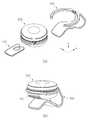
- FIG. 1shows the overall appearance of a body fluid observation device according to an example of the present invention
- FIG. 2illustrates an example in which the body holder 300 is further coupled to the body 200 of the body fluid observation device according to an example of the present invention
- 3is a diagram for explaining an example in which the body fluid monitoring device shown in FIG. 2 is coupled to the user terminal 10 and used
- FIG. 4is a body fluid monitoring device coupled to the user terminal 10. When used, it is a diagram for explaining an example of a bodily fluid image observed through the user terminal 10 .
- the body fluid observation devicemay include a chamber 100 and a body 200 .
- the chamber 100has a length in the first horizontal direction (x), and the user's bodily fluid can be seated.
- the chamber 100may be provided with a collecting liquid receiving groove 110 in which the user's bodily fluid is seated. have.
- the main body 200may include a chamber insertion hole H200a into which the chamber 100 is inserted and an observation hole H200b provided on the bottom surface of the main body 200 for observing the body fluid in order to observe the body fluid.
- the user's bodily fluidcan be observed through the observation hole H200b.
- the lens unit 250may be coupled to the observation hole H200b so that an image of the body fluid can be enlarged and observed, and the user may observe the user's body fluid through the observation hole H200b with the naked eye.
- the present inventionis not necessarily limited thereto, and the body fluid observation device according to an example of the present invention can be used in combination with the user terminal 10 equipped with a camera.
- a body fluid analysis program or application for analyzing video image information acquired through a body fluid observation devicemay be installed.
- the user terminal 10may include both wired and wireless communication devices as long as it is a communication device, and includes a mobile phone, a smart phone, a tablet computer, a laptop computer, a portable media player, a personal digital assistant (PDA), It may include a wearable device including a smart watch or smart glasses capable of wireless communication, a navigation device, and the like.
- a communication deviceincludes a mobile phone, a smart phone, a tablet computer, a laptop computer, a portable media player, a personal digital assistant (PDA), It may include a wearable device including a smart watch or smart glasses capable of wireless communication, a navigation device, and the like.
- PDApersonal digital assistant
- the image image information captured by the camera of the user terminal 10is transmitted to another electronic communication device in which the body fluid analysis program or application is installed. It is also possible to use
- the body fluid observation devicemay further include a body holder 300 capable of being coupled to the user terminal 10 .
- the body holder 300may be fitted to the outer surface of the body 200 as shown in (b) of FIG. 2, and as shown in FIG. 3, a device having a camera, that is, a user terminal ( 10) to fix the body 200 .
- FIG. 4It can be photographed as a).
- the state or activity of the bodily fluidcan be analyzed, so that the user's bodily fluid can be conveniently used without visiting a specialized medical institution. can be analyzed, so that the user's convenience and convenience can be further expanded.
- FIG 5is a view for explaining an example of the chamber 100 in the body fluid observation device according to an example of the present invention.
- FIG. 5 (b)is a cross-sectional view of the line I-I of FIG. 5 (a).
- the chamber 100has a length in the first horizontal direction (x), it may be provided with a receiving liquid receiving groove 110 in which the user's liquid collection is seated. .
- a liquid receiving groove 110may be formed by being depressed inwardly from the upper surface of the chamber 100 .
- the depression depth T2 of the liquid receiving groove 110may be greater than 1/2 of the chamber thickness T1, and may be less than 9/10 of the chamber thickness T1.
- a separate insertion memberis inserted in accordance with the collecting liquid receiving groove 110 (not shown) may be further provided.
- At least the bodily fluid receiving groove 110 in the chamber 100may be transparent or translucent.
- only the bodily fluid receiving groove 110 in the chamber 100may be transparent or translucent, and the remaining portion may be opaque, or the entire chamber 100 including the bodily fluid receiving groove 110 may be transparent or translucent. Accordingly, the user's bodily fluid seated in the bodily fluid receiving groove 110 can be easily observed from the rear surface of the bodily fluid receiving groove 110 .
- the body 200 into which the chamber 100 is seated is inserted by the user's chamber 100may be formed as shown in FIGS. 6 and 7 .
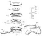
- FIG. 6is an exploded view of the body 200 of the body fluid observation device according to an example of the present invention
- FIG. 7is a vertical cross-sectional view of the body 200 of the body fluid observation device according to an example of the present invention
- FIG. 6 and 7are diagrams for explaining the case 210 in more detail
- FIG. 9is a diagram for explaining the asymmetric structure of the chamber 100 and the guide partition walls R211x and R211y.
- the body 200 of the body fluid observation deviceincludes a case 210, an operation unit 220, a power supply unit 230, a light source unit 240, and a lens unit ( 250) may be included.
- the case 210may include first, second, and third case parts 211 , 213 , and 215 , and the first case part 211 is the main body 200 .
- the second case portion 213may be located in the middle portion of the main body 200
- the third case portion 215may be located in the upper portion of the main body 200 .
- the first case portion 211includes a space in which the chamber 100 can be inserted, a space in which the light source unit 240 and the operation unit 220 can be located, and the lens unit 250 .
- the second case part 213is positioned on the first case part 211 to cover the operation unit 220 , the space into which the chamber 100 is inserted, the light source unit 240 and the operation unit 220 .
- the third case part 215may be disposed on the second case part 213 to cover the power supply unit 230 and be detachably attached to the second case part 213 so that the user can easily replace the battery. have.
- the first case part 211may include a chamber insertion hole H200a, guide partition walls R211x and R211y, and an observation hole H200b, as shown in FIG. 8 .
- the chamber insertion hole H200ais located on the front side of the main body 200 into which the chamber 100 is inserted, and a part of the first case 210 part is opened to have a length in the second horizontal direction (y) to open the chamber 100 . ) can be inserted.
- the guide partition walls R211x and R211ymay be positioned on the bottom surface of the first case part 211 , and extend in the first horizontal direction (x) from the chamber insertion hole H200a to insert the chamber 100 in the insertion direction and position. can guide you.
- the guide partition walls R211x and R211yinclude a first guide partition wall R211x extending in the first horizontal direction x and a second guide partition wall R211x extending in the second horizontal direction y from the end of the first horizontal direction x.
- a guide partition wall R211ymay be included.
- the shape of the second guide partition wall R211ymay correspond to the planar shape of the end of the chamber 100 in the first horizontal direction (x). That is, in the chamber 100 of FIG. 5 , a portion adjacent to the center line II of the chamber 100 among the ends in the first horizontal direction (x) has a recessed portion, and the first and second horizontal directions (x, y)
- a planar shapemay be provided to be inclined in an oblique direction, and as shown in FIG. 8 , the shape of the second guide partition wall R211y also includes a portion recessed inward at the end of the center line in the first horizontal direction (x). and may have a planar shape so as to be inclined diagonally in the first and second horizontal directions.
- the guide partition walls R211x and R211ymay more accurately guide positions of the chamber 100 in the first and second horizontal directions.
- the guide partition walls R211x and R211ycan guide the chamber 100 so that it can be accurately positioned at a desired portion when the chamber 100 is inserted into the body 200 through the chamber insertion hole H200a. and the bodily fluid seating groove 110 of the chamber 100 can be accurately positioned on the observation hole H200b.
- each of the chamber 100 and the guide partition walls R211x and R211y according to an example of the present inventionmay have an asymmetric shape with respect to the center line as shown in FIG. 9 .
- the planar shape of the end of the first horizontal direction (x) in the chamber 100is asymmetric with respect to the center line CL100 parallel to the first horizontal direction (x).
- the shape of the second guide partition wall R211y extending in the second horizontal direction y from the guide partition walls R211x and R211yis based on a center line CL211 parallel to the first horizontal direction x. Both sides may be formed asymmetrically with each other.
- the chamber 100may have a chamfer portion P100 formed at an end in the first horizontal direction (x) in which one corner portion is formed in the first and second horizontal directions and diagonal directions with respect to the center line CL100. have.
- the guide partition walls R211x and R211yare also at the ends of the first horizontal direction (x) with respect to the center line CL211 at any one of the corners of the chamber 100 .
- the first and second guide barrier ribs R211x and R211ymay have chamfered barrier ribs PR211 formed in an oblique direction to correspond to the shape of the chamfered portion P100.
- FIGS. 9 (b) and (c)only when the chamber 100 is inserted according to an intended or desired direction, the chamber 100 is completely inserted into the body 200. Also, when the chamber 100 is inserted in a different direction than intended or desired, the chamber 100 may not be completely inserted into the body 200 .
- the observation hole H200bis formed on the bottom surface of the first case part 211 to observe body fluid, and may be provided on the bottom surface of the main body 200 , and the chamber 100 . ) may be overlapped with the body fluid receiving groove 110 in the vertical direction (z).
- the lens unit 250 fixedly coupled to the observation hole H200b to enlarge the image of the body fluidmay be provided in the observation hole H200b as shown in FIG. 8 .
- the magnification of the lens unit 250may be, for example, between 100 times and 500 times, and is coupled to a camera provided in the user terminal 10 to reduce the body fluid seated in the chamber 100 by 700 times to 1300 times. It can be enlarged by magnification.
- the present inventionis not necessarily limited to the magnification of the above-described lens unit 250 .
- the light source unit 240is positioned above the bodily fluid receiving groove 110 of the chamber 100 to irradiate light to the bodily fluid receiving groove 110 . Accordingly, the user can observe the body fluid more clearly.
- the operation unit 220may be located in the upper portion of the chamber 100 in the first case portion 211 , and electrically connected to the light source unit 240 , the light source unit 240 . can operate.
- the operation unit 220may include substrates 221 and 223 provided with electrical circuit patterns for operating the light source unit 240 , and the light source unit 240 is located at the center of the substrates 221 and 223 . However, it may be located above the body fluid seating portion of the chamber 100 .
- the operation unit 220forms an electrical closed loop for operating the light source unit 240 as the chamber 100 is inserted into the chamber insertion hole H200a, and accordingly, the operation unit 220 operates the light source unit 240 By operating it, the light source unit 240 may be irradiated with light.
- the usercan more clearly observe the bodily fluid located in the bodily fluid receiving groove 110 of the chamber 100 through the observation hole H200b with the naked eye or through the user terminal 10 .
- the operation unit 220is a first substrate formed in multiple layers. A 221 and a second substrate 223 may be provided.
- the first substrate 221is provided with a circuit pattern electrically connected to the light source unit 240 , the light source unit 240 may be located in the middle of the first substrate 221 , and the second substrate 223 is the second substrate 223 .
- the first substrate 221may be disposed under the first substrate 221 , and may be electrically connected to the first substrate 221 , and an operation switch 225 that forms an electrically closed loop when the chamber 100 is inserted may be provided. This will be described in more detail with reference to FIGS. 10 and 11 .
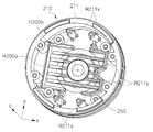
- FIG. 10is a diagram for explaining in more detail an example of the operation unit 220 according to the present invention
- FIG. 11is a diagram for explaining a method of operating the operation unit 220 shown in FIG. 9
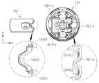
- FIG. 12is a diagram for explaining another example of the operation unit 220 according to the present invention.
- FIG. 10(a) of FIG. 10 is a perspective view of the operating unit 220, and FIG. 10 (b) is the operating unit 220 shown in FIG. 10 (a) in the second horizontal direction (y). A cut section is shown.
- an example of the operation unit 220is an operation of forming an electrical closed loop for operating the light source unit 240 when the chamber 100 is inserted into the chamber insertion hole H200a.
- a switch 225may be included.
- the operation unit 220may be formed in multiple layers, and may include a first substrate 221 positioned on an upper portion and a second substrate 223 positioned on a lower portion.
- the first substrate 221may have a light source unit 240 positioned in the middle, and power supply connection terminals E1 and E2 to which a battery of the power supply unit is connected may be provided on the first substrate 221 .
- the second substrate 223has a light transmission hole H223 through which the light irradiated from the light source unit 240 passes in the middle portion of the second substrate 223 so that the light emitted from the light source unit 240 located thereon is transmitted.
- a light transmission hole H223through which the light irradiated from the light source unit 240 passes in the middle portion of the second substrate 223 so that the light emitted from the light source unit 240 located thereon is transmitted.
- the diameter (R1) of the light transmission holemay be, for example, between 0.5 mm and 2.5 mm, but this is an example, and the diameter (R1) of the light transmission hole is the light source unit 240 and the light transmission hole (H223) It may vary depending on the distance between them.
- first substrate 221 and the second substrate 223may be electrically connected to each other.
- a first connector 227amay be provided on a lower portion of the first board 221
- a second connector 227bmay be provided on an upper portion of the second board 223
- a second connector 227amay be provided on the first connector 227a .
- the connector 227bmay be inserted so that the first substrate 221 and the second substrate 223 may be electrically connected to each other.
- An operation switch 225 forming an electrical closed loopmay be provided under the second substrate 223 , and each operation switch 225 has a light transmission hole H223 located in the middle of the second substrate 223 . ), the switch terminal may protrude.
- the operation switch 225may be located on an extension line of the guide partition walls R211x and R211y.
- the operation switch 225may be positioned on an extension line of the first guide partition wall R211x extending in the first horizontal direction (x) as shown in FIG. 11 , and the operation switch 225 is a switch of the operation switch 225 , for example.
- the terminalmay be provided such that the switch terminal of the operation switch 225 is pressed by the chamber 100 when the chamber 100 is inserted by protruding inward from the extension line of the guide partition walls R211x and R211y.
- the present inventionis not necessarily limited thereto, and the operation switch 225 may be positioned on an extension line of the second guide partition wall R211y extending in the second horizontal direction y. That is, the operation switch 225 may be positioned on the side of the second guide partition wall R211y so as to contact the end of the chamber 100 in the first horizontal direction (x).
- the chamber 100is inserted into the chamber insertion hole H200a. It is turned on by being pressed by the chamber 100 to form an electrical closed loop for operating the light source unit 240 .
- the operation unit 220 of the present inventionis not necessarily limited to the structure including the operation switch 225 as shown in FIGS. 10 and 11 , and may have other structures.
- the operation unit 220when the chamber 100 is inserted into the chamber insertion hole H200a, the operation unit 220 according to another example of the present invention may form a structure that forms an electrically closed loop together with the chamber 100 .
- the chamber 100may include chamber electrodes 100E1 and 100E2 having an electrode pattern of a conductive material at an end in the first horizontal direction (x).
- the chamber electrodes 100E1 and 100E2may include first and second chamber electrodes 100E1 and 100E2 formed in the vertical direction (z) at the end of the first horizontal direction (x) in the chamber 100,
- the first and second chamber electrodes 100E1 and 100E2may be spaced apart from each other in the second direction, and the first and second chamber electrodes 100E1 and 100E2 may be electrically connected to each other by a chamber electrode line 100CE.
- the operation unit 220is positioned on a portion of the guide partition walls R211x and R211y corresponding to the chamber electrodes 100E1 and 100E2 to form an electrical closed loop, and as the chamber 100 is inserted, the chamber electrode Guide electrodes 210E1 and 210E2 connected to 100E1 and 100E2 may be provided.
- a position corresponding to the chamber electrodes 100E1 and 100E2 in the guide barrier ribs R211x and R211ymay be, for example, an inner side of the second guide barrier rib R211y, and the guide electrodes 210E1 and 210E2 are the second guide barrier ribs ( R211y) may be formed in the vertical direction (z).
- the guide electrodes 210E1 and 210E2may be electrically connected to circuit patterns of the substrates 221 and 223 included in the operation unit 220 .
- the guide electrodes 210E1 and 210E2 provided in the guide partition walls R211x and R211y and the chamber electrodes 100E1 and 100E2 provided in the chamber 100 )contact each other to form an electrical closed loop for driving the light source unit 240 .
- the userallows light to be irradiated from the light source unit 240 naturally by the operation of inserting the chamber 100 into the body 200 to observe the body fluid without a separate operation, so that the body fluid can be observed more conveniently. can do.
Landscapes
- Health & Medical Sciences (AREA)
- Life Sciences & Earth Sciences (AREA)
- Engineering & Computer Science (AREA)
- Biomedical Technology (AREA)
- Physics & Mathematics (AREA)
- Molecular Biology (AREA)
- General Health & Medical Sciences (AREA)
- Pathology (AREA)
- Public Health (AREA)
- Medical Informatics (AREA)
- Heart & Thoracic Surgery (AREA)
- Surgery (AREA)
- Animal Behavior & Ethology (AREA)
- Biophysics (AREA)
- Veterinary Medicine (AREA)
- Chemical & Material Sciences (AREA)
- Hematology (AREA)
- Urology & Nephrology (AREA)
- Optics & Photonics (AREA)
- Food Science & Technology (AREA)
- Medicinal Chemistry (AREA)
- Analytical Chemistry (AREA)
- Biochemistry (AREA)
- General Physics & Mathematics (AREA)
- Immunology (AREA)
- Reproductive Health (AREA)
- Endoscopes (AREA)
- Apparatus Associated With Microorganisms And Enzymes (AREA)
Abstract
Description
Translated fromKorean본 발명은 사용자의 체액을 관찰할 수 있는 체액 관찰 기기에 관한 것이다.The present invention relates to a body fluid observation device capable of observing a user's body fluid.
일반적으로 사람들은 자신의 건강상태, 신체상태를 확인하기 위해 전문의료기관을 방문해야 한다. 그러나, 전문의료 기관을 방문하여 검진을 받기 위해서는 바쁜 일과시간을 쪼개어 시간을 내야 하며, 불편하고 복잡한 수속 및 진료과정을 진행해야 한다.In general, people have to visit specialized medical institutions to check their health and physical condition. However, in order to visit a specialized medical institution and receive a checkup, it is necessary to divide the busy work hours into time, and to proceed with inconvenient and complicated procedures and treatment procedures.
특히, 대부분이 이러한 수속을 진행하더라도 장시간 대기해야 검사를 받을 수 있는 반면, 실제 검진 및 검사는 매우 짧은 시간에 진행된다. 즉, 검진 및 검사를 받기 위해 시간과 비용이 크게 소요되며, 많은 불편이 따르는 실정이다.In particular, although most of them have to wait for a long time to receive an examination even if they go through these procedures, the actual examination and examination are carried out in a very short time. In other words, it takes a lot of time and money to undergo a checkup and examination, and a lot of inconvenience is caused.
이로 인해 대부분의 사람들은 어지간한 불편함은 감수하며 생활하고 견디기 힘들 정도의 고통 또는 불편함이 발생해야만 전문의료기관을 이용하는 실정이다.As a result, most people live with some discomfort and use a specialized medical institution only if they experience unbearable pain or discomfort.
이러한, 불편을 해소하기 위해 각종 첨단장비를 이용하여 신체상황을 빈번하게 확인하고, 이를 네트워크를 통해 전문의료기관에 전달하여 신체 상태를 확인하는 기술들이 개발되어 있지만, 실제로 상용화되어 이용되는 기술은 극히 드문 실정이다.In order to solve this inconvenience, technologies have been developed that frequently check the physical condition using various advanced equipment and transmit it to a specialized medical institution through a network to check the physical condition, but the technology that is actually commercialized and used is extremely rare. the current situation.
오히려, 과거로부터 사용되어온 간단한 테스트기의 사용은 꾸준하며, 젊은 세대들은 특히 편리한 사용법, 적은 소요 시간 및 비용, 빠른 결과 확인이 가능하여 사용률이 꾸준히 증가하는 추세이다.Rather, the use of simple testers that have been used in the past is steady, and the use rate of the younger generation is steadily increasing because of the convenient use, short time and cost, and quick result confirmation.
이러한 테스트기는 신체에서 배출되는 체액, 예를 들어 타액, 소변, 땀과 같은 분비물들을 이용하는 것으로, 분비물들에 포함된 호르몬을 검출하거나, 분비물의 상태변화와 같은 사항을 확인하는 방법이 이용될 수 있다.These test devices use body fluids discharged from the body, for example, secretions such as saliva, urine, and sweat, and methods for detecting hormones contained in secretions or checking matters such as changes in the state of secretions can be used. .
테스트기는 신체가 특정 상황 예를 들어, 특정 질병에 걸리거나, 감염되거나, 배란기와 같이 신체의 이상 또는 특이사항 발생시에 체액에 포함된 성분의 변화, 상태의 변화가 발생하는 것을 이용하여, 사용자의 신체 상태를 관찰할 수 있다.The test device uses the occurrence of changes in components and conditions in body fluids when the body is affected by a specific situation, for example, a specific disease, infection, or abnormal or unusual body conditions such as ovulation. physical condition can be observed.
본 발명은 사용자의 체액을 관찰할 수 있는 체액 관찰 기기를 제공하는데, 그 목적이 있다.An object of the present invention is to provide a body fluid observation device capable of observing a user's body fluid.
본 발명의 일례에 따른 체액 관찰 기기는 제1 수평 방향으로 길이를 가지며, 사용자의 체액이 안착되는 챔버; 체액을 관찰하기 위해 챔버가 삽입되는 본체;를 포함하고, 본체는 본체의 전면에 챔버가 삽입되는 챔버 삽입홀, 챔버 삽입홀로부터 제1 수평 방향으로 연장되어 챔버를 가이드하는 가이드 격벽 및 본체의 바닥면에 구비되어 체액을 관찰하는 관찰홀을 구비하는 케이스; 케이스의 내에서 챔버의 상부에 위치하고, 빛을 발광하는 광원부; 및 광원부에 전기적으로 연결되어, 광원부를 동작시키는 동작부;를 포함하고, 챔버가 챔버 삽입홀로 삽입됨에 따라, 동작부는 광원부를 동작시키는 전기적 폐루프를 형성시킬 수 있다.A body fluid observation device according to an example of the present invention includes a chamber having a length in a first horizontal direction, in which a user's body fluid is seated; a body into which a chamber is inserted to observe body fluid; the body includes a chamber insertion hole into which the chamber is inserted in the front surface of the body, a guide partition wall extending in a first horizontal direction from the chamber insertion hole to guide the chamber, and the bottom of the body a case provided on the surface and having an observation hole for observing body fluids; a light source unit located in the upper part of the chamber in the case and emitting light; and an operation unit electrically connected to the light source unit to operate the light source unit, and as the chamber is inserted into the chamber insertion hole, the operation unit may form an electrically closed loop for operating the light source unit.
챔버는 체액이 안착되는 부분이 함몰된 체액 안착홈;을 포함하고, 챔버에서 적어도 체액 안착홈은 투명 또는 반투명할 수 있다.The chamber may include a bodily fluid receiving groove in which a body fluid receiving portion is recessed, and at least the bodily fluid receiving groove in the chamber may be transparent or translucent.
가이드 격벽은 제1 수평 방향의 끝단에서 제1 수평 방향과 교차하는 제2 수평 방향으로 연장되고, 제2 수평 방향으로 연장된 가이드 격벽의 형상은 챔버의 제1 수평 방향 끝단의 평면 형상에 대응될 수 있다.The guide partition wall extends in a second horizontal direction intersecting the first horizontal direction from the end of the first horizontal direction, and the shape of the guide partition wall extending in the second horizontal direction corresponds to the planar shape of the first horizontal end of the chamber. can
챔버에서 제1 수평 방향 끝단의 평면 형상은 제1 수평 방향과 나란한 중심선을 기준으로 양쪽이 비대칭이고, 가이드 격벽에서 제2 수평 방향으로 연장되는 가이드 격벽의 형상은 제1 수평 방향과 나란한 중심선을 기준으로 양쪽이 서로 비대칭일 수 있다.The planar shape of the end of the first horizontal direction in the chamber is asymmetric on both sides with respect to the center line parallel to the first horizontal direction, and the shape of the guide partition wall extending from the guide partition wall in the second horizontal direction is based on the center line parallel to the first horizontal direction Both sides may be asymmetric to each other.
동작부는 챔버 삽입홀로 챔버가 삽입되는 동안, 챔버에 의해 눌림으로 턴 온되고, 전기적 폐루프를 형성하는 동작 스위치를 포함할 수 있다.The operation unit may include an operation switch that is turned on by being pressed by the chamber while the chamber is inserted into the chamber insertion hole, and forms an electrical closed loop.
동작 스위치는 가이드 격벽의 연장선 상에 위치할 수 있다.The operation switch may be located on an extension line of the guide partition wall.
동작부는 광원부와 전기적으로 연결되는 회로 패턴이 구비되는 제1 기판; 제1 기판 하부에 위치하여, 제1 기판에 전기적으로 연결되고, 하부에 동작 스위치가 구비되는 제2 기판;을 포함하고, 동작 스위치는 제2 기판의 하부에서 가이드 격벽의 연장 선상에 중첩되도록 고정될 수 있다.The operation unit includes: a first substrate provided with a circuit pattern electrically connected to the light source unit; a second substrate positioned under the first substrate, electrically connected to the first substrate, and provided with an operation switch thereunder, wherein the operation switch is fixed to overlap the extension line of the guide barrier rib from the lower portion of the second substrate can be
제1 기판의 가운데 부분에는 광원부가 위치하고, 제2 기판의 가운데 부분에는 광원부에서 조사되는 빛이 통과되는 광투과홀이 구비될 수 있다.The light source unit may be positioned in a central portion of the first substrate, and a light transmission hole through which the light emitted from the light source unit passes may be provided in the middle portion of the second substrate.
챔버는 전도성 재질의 전극 패턴을 갖는 챔버 전극;을 구비하고, 동작부는 전기적 폐루프를 형성하기 위하여, 챔버 전극과 대응되는 가이드 격벽의 일부 위에 위치하여, 챔버가 삽입됨에 따라, 챔버 전극에 접속되는 가이드 전극을 포함할 수 있다.The chamber includes a chamber electrode having an electrode pattern of a conductive material, and the operation unit is located on a part of the guide barrier rib corresponding to the chamber electrode to form an electrical closed loop, and is connected to the chamber electrode as the chamber is inserted A guide electrode may be included.
본체는 케이스의 관찰홀에 고정 결합되어 체액에 대한 이미지를 확대하는 렌즈부를 더 구비할 수 있다.The body may further include a lens unit that is fixedly coupled to the observation hole of the case to enlarge the image of the body fluid.
본체의 외측면에 끼움 결합되어, 카메라를 구비한 기기에 본체를 고정시키는 본체 홀더;를 더 포함할 수 있다.It may further include a body holder fitted to the outer surface of the body to fix the body to a device having a camera.
본 발명의 일례에 따른 체액 관찰 기기는 챔버가 챔버 삽입홀을 통하여 본체 내부로 삽입됨에 따라, 동작부가 광원부를 동작시키는 전기적 폐루프를 형성함으로써, 사용자가 보다 편리하게 체액을 관찰하도록 할 수 있다.In the apparatus for observing body fluid according to an example of the present invention, as the chamber is inserted into the body through the chamber insertion hole, the operation unit forms an electrically closed loop for operating the light source, so that the user can more conveniently observe the body fluid.
도 1은 본 발명의 일례에 따른 체액 관찰 기기의 전체 외형을 도시한 것이다.1 is a view showing the overall appearance of a body fluid observation device according to an example of the present invention.
도 2는 본 발명의 일례에 따른 체액 관찰 기기의 본체(200)에 본체 홀더(300)가 더 결합된 예를 설명하기 위한 도이다.2 is a view for explaining an example in which the
도 3은 도 2에 도시된 체액 관찰 기기가 사용자 단말기(10)에 결합되어 사용되는 일례를 설명하기 위한 도이다.FIG. 3 is a diagram for explaining an example in which the body fluid monitoring device shown in FIG. 2 is coupled to the
도 4는 체액 관찰 기기가 사용자 단말기(10)와 결합되어 사용되는 경우, 사용자 단말기(10)를 통하여 관찰되는 체액 이미지의 일례를 설명하기 위한 도이다.4 is a diagram for explaining an example of a body fluid image observed through the
도 5은 본 발명의 일례에 따른 체액 관찰 기기에서 챔버(100)의 일례를 설명하기 위한 도이다.5 is a view for explaining an example of the
도 6은 본 발명의 일례에 따른 체액 관찰 기기의 본체(200)를 분해한 분해도이다.6 is an exploded view of the
도 7은 본 발명의 일례에 따른 체액 관찰 기기의 본체(200)에 대한 수직 단면도이다.7 is a vertical cross-sectional view of the
도 8은 도 6 및 도 7에서 케이스(210)에 대해 보다 구체적으로 설명하기 위한 도이다.8 is a diagram for describing the
도 9는 챔버(100)와 가이드 격벽(R211x, R211y)의 비대칭 구조를 설명하기 위한 도이다.9 is a view for explaining an asymmetric structure of the
도 10는 본 발명에 따른 동작부(220)의 일례에 대해 보다 상세하게 설명하기 위한 도이다.10 is a diagram for explaining in more detail an example of the
도 11은 도 9에 도시된 동작부(220)가 동작되는 방법을 설명하기 위한 도이다.11 is a diagram for explaining a method in which the
도 12는 본 발명에 따른 동작부(220)의 다른 일례를 설명하기 위한 도이다.12 is a diagram for explaining another example of the
이하, 첨부된 도면을 참조하여 본 발명의 실시예들을 상세히 설명한다. 본 발명을 설명하는데 있어서, 해당 분야에 이미 공지된 기술 또는 구성에 대한 구체적인 설명을 부가하는 것이 본 발명의 요지를 불분명하게 할 수 있다고 판단되는 경우에는 상세한 설명에서 이를 일부 생략하도록 한다. 또한, 본 명세서에서 사용되는 용어들은 본 발명의 실시예들을 적절히 표현하기 위해 사용된 용어들로서, 이는 해당 분야의 관련된 사람 또는 관례 등에 따라 달라질 수 있다. 따라서, 본 용어들에 대한 정의는 본 명세서 전반에 걸친 내용을 토대로 내려져야 할 것이다.Hereinafter, embodiments of the present invention will be described in detail with reference to the accompanying drawings. In describing the present invention, if it is determined that adding a detailed description of a technique or configuration already known in the relevant field may make the gist of the present invention unclear, some of these will be omitted from the detailed description. In addition, the terms used in this specification are terms used to properly express embodiments of the present invention, which may vary according to a person or custom in the relevant field. Accordingly, definitions of these terms should be made based on the content throughout this specification.
이하에서, 제1 수평 방향과 제2 수평 방향에 대해, 평면 상에서 어느 하나의 방향을 제1 수평 방향이라고 정의한 경우, 제2 수평 방향은 제1 수평 방향과 엇갈리거나 교차하는 방향을 의미한다. 즉, 제2 수평 방향은 제1 수평 방향에 직각으로 교차할 수 있으나, 반드시 직각에 한정되는 것은 아니고, 직각에 유사한 범위까지 포함될 수 있다.Hereinafter, when any one direction on a plane is defined as the first horizontal direction with respect to the first horizontal direction and the second horizontal direction, the second horizontal direction means a direction crossing or intersecting the first horizontal direction. That is, the second horizontal direction may intersect the first horizontal direction at a right angle, but is not necessarily limited to a right angle, and may include a range similar to the right angle.
수직 방향은 제1, 2 수평 방향이 이루는 수평면에 교차하는 방향을 의미하고, 일례로, 수직 방향은 제1, 2 수평 방향에 수직으로 교차할 수 있으나, 반드시 수직에 한정되는 것은 아니고, 수직에 유사한 범위까지 포함될 수 있다.The vertical direction means a direction crossing a horizontal plane formed by the first and second horizontal directions, and for example, the vertical direction may vertically intersect the first and second horizontal directions, but is not necessarily limited to vertical. Similar ranges may be included.
이하, 첨부된 도면을 참조하여 본 발명의 일례에 따른 체액 관찰 기기에 대해서 설명한다.Hereinafter, a body fluid observation device according to an example of the present invention will be described with reference to the accompanying drawings.
도 1은 본 발명의 일례에 따른 체액 관찰 기기의 전체 외형을 도시한 것이고, 도 2는 본 발명의 일례에 따른 체액 관찰 기기의 본체(200)에 본체 홀더(300)가 더 결합된 예를 설명하기 위한 도이고, 도 3은 도 2에 도시된 체액 관찰 기기가 사용자 단말기(10)에 결합되어 사용되는 일례를 설명하기 위한 도이고, 도 4는 체액 관찰 기기가 사용자 단말기(10)와 결합되어 사용되는 경우, 사용자 단말기(10)를 통하여 관찰되는 체액 이미지의 일례를 설명하기 위한 도이다.FIG. 1 shows the overall appearance of a body fluid observation device according to an example of the present invention, and FIG. 2 illustrates an example in which the
도 1의 (a) 및 (b)에 도시된 바와 같이, 본 발명의 일례에 따른 체액 관찰 기기는 챔버(100)와 본체(200)를 포함할 수 있다.As shown in FIGS. 1A and 1B , the body fluid observation device according to an example of the present invention may include a
챔버(100)는 제1 수평 방향(x)으로 길이를 가지며, 사용자의 체액이 안착될 수 있으며, 이를 위해, 챔버(100)에는 사용자의 채액이 안착되는 채액 안착홈(110)을 구비할 수 있다.The
본체(200)는 체액을 관찰하기 위해, 챔버(100)가 삽입되는 챔버 삽입홀(H200a)과 본체(200)의 바닥면에 구비되어 체액을 관찰하는 관찰홀(H200b)을 구비할 수 있다.The
사용자의 채액이 안착된 챔버(100)를 챔버 삽입홀(H200a)을 통하여 본체(200) 내로 삽입한 후, 관찰홀(H200b)을 통하여 사용자의 체액을 관찰할 수 있다.After the
여기서, 관찰홀(H200b)에는 체액에 대한 이미지를 확대 관찰 가능하도록 렌즈부(250)가 결합될 수 있으며, 사용자는 육안으로 관찰홀(H200b)을 통하여 사용자의 체액을 관찰할 수 있다.Here, the
그러나, 본 발명이 반드시 이에 한정되는 것은 아니고, 본 발명의 일례에 따른 체액 관찰 기기는 카메라가 구비된 사용자 단말기(10)와 결합되어 사용 가능하다.However, the present invention is not necessarily limited thereto, and the body fluid observation device according to an example of the present invention can be used in combination with the
사용자 단말기(10)에는 체액 관찰 기기를 통하여 획득된 영상 이미지 정보를 분석하는 체액 분석 프로그램 또는 애플리케이션이 설치될 수 있다.In the
일례로, 사용자 단말기(10)는 통신 가능한 장치라면 유선 또는 무선 통신 장치 모두 포함될 수 있고, 휴대 전화기, 스마트폰, 태블릿 컴퓨터, 랩톱 컴퓨터, 포터블 미디어 플레이어, 개인용 디지털 단말기 (Personal Digital Assistant, PDA), 무선통신이 가능한 스마트 시계 또는 스마트 안경 등을 포함하는 웨어러블 장치 및 내비게이션 장치 등을 포함할 수 있다.For example, the
그러나, 사용자 단말기(10)에 체액 분석 프로그램 또는 애플리케이션이 설치되지 않았다고 하더라도, 사용자 단말기(10)의 카메라를 통해 촬영되어 획득된 영상 이미지 정보가 체액 분석 프로그램 또는 애플리케이션이 설치된 다른 전자 통신 기기로 전송되어 사용되는 것도 가능하다.However, even if the body fluid analysis program or application is not installed in the
이를 위해, 도 2의 (a) 및 (b)에 도시된 바와 같이, 본 발명의 일례에 따른 체액 관찰 기기는 사용자 단말기(10)와 결합 가능한 본체 홀더(300)를 더 포함할 수 있다.To this end, as shown in (a) and (b) of FIG. 2 , the body fluid observation device according to an example of the present invention may further include a
본체 홀더(300)는 도 2의 (b)에 도시된 바와 같이, 본체(200)의 외측면에 끼움 결합될 수 있으며, 도 3에 도시된 바와 같이, 카메라를 구비한 기기, 즉 사용자 단말기(10)에 결합되어 본체(200)를 고정시킬 수 있다.The
이와 같이, 도 3의 (a) 및 (b)에 도시된 바와 같이, 체액 분석 프로그램 또는 애플리케이션이 설치된 사용자 단말기(10)에 체액 관찰 기기를 결합하여, 사용자의 체액을 촬영하면, 도 4의 (a)와 같이 촬영될 수 있다.In this way, as shown in (a) and (b) of FIG. 3 , when a body fluid monitoring device is coupled to the
이를, 체액 분석 프로그램 또는 애플리케이션을 이용하여 분석하면, 도 4의 (b)에 도시된 바와 같이, 체액의 상태나 활동성 등을 분석할 수 있어, 전문 의료 기관에 방문할 필요없이 편리하게 사용자의 체액을 분석할 수 있어, 사용자의 편리성 및 편의성을 보다 확장시킬 수 있다.If this is analyzed using a bodily fluid analysis program or application, as shown in FIG. 4(b), the state or activity of the bodily fluid can be analyzed, so that the user's bodily fluid can be conveniently used without visiting a specialized medical institution. can be analyzed, so that the user's convenience and convenience can be further expanded.
이하에서는 이와 같은 체액 테스트 기기의 구체적이 구조에 대해 살펴본다.Hereinafter, a detailed structure of such a bodily fluid test device will be described.
도 5은 본 발명의 일례에 따른 체액 관찰 기기에서 챔버(100)의 일례를 설명하기 위한 도이다.5 is a view for explaining an example of the
도 5에서 (b)는 도 5 (a)의 I-I 라인의 단면을 절단한 형태를 도시한 것이다. 도 5의 (a) 및 (b)에 도시된 바와 같이, 챔버(100)는 제1 수평 방향(x)으로 길이를 가지며, 사용자의 채액이 안착되는 채액 안착홈(110)을 구비할 수 있다. 이와 같은 채액 안착홈(110)은 챔버(100)의 상부면으로부터 내측으로 함몰되어 형성될 수 있다.In FIG. 5 (b) is a cross-sectional view of the line I-I of FIG. 5 (a). As shown in (a) and (b) of Figure 5, the
여기서, 채액 안착홈(110)의 함몰 깊이(T2)는 챔버 두께(T1)의 1/2보다 클 수 있으며, 챔버 두께(T1)의 9/10보다 작을 수 있다.Here, the depression depth T2 of the
이와 같은 채액 안착홈(110)에는 채액이 안착된 이후, 모세관 현상을 이용하여 채액이 채액 안착홈(110) 내에 골고루 퍼질 수 있도록 하기 위하여, 채액 안착홈(110)에 맞추어 삽입되는 별도의 삽입 부재(미도시)가 더 구비될 수 있다.After the collecting liquid is seated in the collecting
이와 같은 챔버(100)에서 적어도 체액 안착홈(110)은 투명 또는 반투명할 수 있다. 일례로, 챔버(100)에서 체액 안착홈(110)만 투명 또는 반투명하고, 나머지 부분은 불투명하거나, 챔버(100)에서 체액 안착홈(110)을 포함한 전체가 투명 또는 반투명할 수 있다. 이에 따라, 체액 안착홈(110)에 안착된 사용자의 체액이 체액 안착홈(110)의 배면에서 쉽게 관찰되도록 할 수 있다.At least the bodily
사용자의 채액을 관찰하기 위해, 사용자의 챔버(100)가 안착된 챔버(100)가 삽입되는 본체(200)는 일례로, 도 6 및 도 7에 도시된 바와 같이 형성될 수 있다.In order to observe the user's liquid, the
도 6은 본 발명의 일례에 따른 체액 관찰 기기의 본체(200)를 분해한 분해도이고, 도 7은 본 발명의 일례에 따른 체액 관찰 기기의 본체(200)에 대한 수직 단면도이고, 도 8은 도 6 및 도 7에서 케이스(210)에 대해 보다 구체적으로 설명하기 위한 도이고, 도 9는 챔버(100)와 가이드 격벽(R211x, R211y)의 비대칭 구조를 설명하기 위한 도이다.6 is an exploded view of the
도 6 및 도 7에 도시된 바와 같이, 본 발명의 일례에 따른 체액 관찰 기기의 본체(200)는 케이스(210), 동작부(220), 전원부(230), 광원부(240) 및 렌즈부(250)를 포함할 수 있다.6 and 7, the
케이스(210)는 도 6 및 도 7에 도시된 바와 같이, 제1, 2, 3 케이스 부분(211, 213, 215)을 포함할 수 있으며, 제1 케이스 부분(211)은 본체(200)의 하부에 위치하고, 제2 케이스 부분(213)은 본체(200)의 중간 부분에, 제3 케이스 부분(215)은 본체(200)의 상부에 위치할 수 있다.As shown in FIGS. 6 and 7 , the
제1 케이스 부분(211)에는 도 1에 도시된 바와 같이, 챔버(100)가 삽입될 수 있는 공간, 광원부(240)와 동작부(220)가 위치할 수 있는 공간과 렌즈부(250)가 구비될 수 있으며, 제2 케이스 부분(213)은 동작부(220)를 덮도록 제1 케이스 부분(211) 위에 위치하여, 챔버(100)가 삽입되는 공간과 광원부(240)와 동작부(220)가 위치하는 공간을 외부로부터 은폐 및 보호하고, 전원부(230)를 형성하는 배터리(Battery)의 위치를 고정하는 역할을 할 수 있다.As shown in FIG. 1 , the
제3 케이스 부분(215)은 전원부(230)를 덮도록 제2 케이스 부분(213) 위에 위치하여, 사용자가 배터리를 쉽게 교체할 수 있도록, 제2 케이스 부분(213)과 탈착 가능하도록 구비될 수 있다.The
여기서, 제1 케이스 부분(211)은 도 8에 도시된 바와 같이, 챔버 삽입홀(H200a), 가이드 격벽(R211x, R211y) 및 관찰홀(H200b)을 구비할 수 있다.Here, the
챔버 삽입홀(H200a)은 챔버(100)가 삽입되는 본체(200)의 전면 쪽에 위치하여, 체1 케이스(210) 부분의 일부가 제2 수평 방향(y)으로 길이를 갖도록 오픈되어 챔버(100)가 삽입될 수 있다.The chamber insertion hole H200a is located on the front side of the
가이드 격벽(R211x, R211y)은 제1 케이스 부분(211)의 바닥면에 위치할 수 있으며, 챔버 삽입홀(H200a)로부터 제1 수평 방향(x)으로 연장되어 챔버(100)의 삽입 방향과 위치를 가이드할 수 있다.The guide partition walls R211x and R211y may be positioned on the bottom surface of the
이와 같은 가이드 격벽(R211x, R211y)은 제1 수평 방향(x)으로 연장되는 제1 가이드 격벽(R211x)과 제1 수평 방향(x)의 끝단에서 제2 수평 방향(y)으로 연장되는 제2 가이드 격벽(R211y)을 포함할 수 있다.The guide partition walls R211x and R211y include a first guide partition wall R211x extending in the first horizontal direction x and a second guide partition wall R211x extending in the second horizontal direction y from the end of the first horizontal direction x. A guide partition wall R211y may be included.
여기서, 제2 가이드 격벽(R211y)의 형상은 챔버(100)의 제1 수평 방향(x) 끝단의 평면 형상에 대응될 수 있다. 즉, 도 5의 챔버(100)에서 제1 수평 방향(x)의 끝단 중 챔버(100)의 중심선(I-I)에 인접한 부분은 함몰된 부분을 가지며, 제1, 2 수평 방향(x, y)에 사선 방향으로 경사지도록 평면 형상이 구비될 수 있는데, 도 8에 도시된 바와 같이, 제2 가이드 격벽(R211y)의 형상 역시, 제1 수평 방향(x)의 중심선 끝단에 내측으로 함몰된 부분을 가지며, 제1, 2 수평 방향에 사선 방향으로 경사지도록 평면 형상이 구비될 수 있다.Here, the shape of the second guide partition wall R211y may correspond to the planar shape of the end of the
이에 따라, 가이드 격벽(R211x, R211y)은 챔버(100)의 제1, 2 수평 방향으로의 위치를 보다 정확하게 가이드할 수 있다.Accordingly, the guide partition walls R211x and R211y may more accurately guide positions of the
이에 따라 가이드 격벽(R211x, R211y)은 챔버(100)가 챔버 삽입홀(H200a)을 통하여 본체(200)의 내부로 삽입될 때, 챔버(100)가 원하는 부분에 정확하게 위치할 수 있도록 가이드할 수 있으며, 챔버(100)의 체액 안착홈(110)이 관찰홀(H200b) 위에 정확하게 위치하도록 할 수 있다.Accordingly, the guide partition walls R211x and R211y can guide the
또한, 본 발명의 일례에 따른 챔버(100)와 가이드 격벽(R211x, R211y) 각각은 도 9에 도시된 바와 같이, 중심선을 기준으로 양쪽이 비대칭 형상을 가질 수 있다.In addition, each of the
즉, 도 9의 (a)에 도시된 바와 같이, 챔버(100)에서 제1 수평 방향(x) 끝단의 평면 형상은 제1 수평 방향(x)과 나란한 중심선(CL100)을 기준으로 양쪽이 비대칭으로 형성될 수 있으며, 가이드 격벽(R211x, R211y)에서 제2 수평 방향(y)으로 연장되는 제2 가이드 격벽(R211y)의 형상은 제1 수평 방향(x)과 나란한 중심선(CL211)을 기준으로 양쪽이 서로 비대칭으로 형성될 수 있다.That is, as shown in (a) of FIG. 9 , the planar shape of the end of the first horizontal direction (x) in the
일례로, 챔버(100)는 제1 수평 방향(x)의 끝단에 중심선(CL100)을 기준으로 어느 한쪽 모서리 부분이 제1, 2 수평 방향과 사선 방향으로 형성된 모따임 부분(P100)을 가질 수 있다.As an example, the
더불어, 도 9의 (a)에 도시된 바와 같이, 가이드 격벽(R211x, R211y) 역시, 제1 수평 방향(x)의 끝단에 중심선(CL211)을 기준으로 어느 한쪽 모서리 부분이 챔버(100)의 모따임 부분(P100) 형상에 대응되도록 제1, 2 가이드 격벽(R211x, R211y)에 사선 방향으로 형성되는 모따임 격벽(PR211)을 가질 수 있다.In addition, as shown in (a) of FIG. 9 , the guide partition walls R211x and R211y are also at the ends of the first horizontal direction (x) with respect to the center line CL211 at any one of the corners of the
이에 따라, 도 9의 (b) 및 (c)에 도시된 바와 같이, 챔버(100)가 의도하거나 원하는 방향에 따라 삽입된 경우만, 챔버(100)가 본체(200) 내부로 완전히 삽입되도록 할 수 있고, 챔버(100)가 의도하거나 원하는 방향과 다르게 삽입된 경우, 챔버(100)가 본체(200) 내부로 완전히 삽입되지 않도록 할 수 있다.Accordingly, as shown in FIGS. 9 (b) and (c), only when the
따라서, 챔버(100)의 상하가 뒤집혀 삽입되는 경우, 챔버(100)가 본체(200) 내부로 온전히 삽입되지 않도록 할 수 있다. 이에 따라, 사용자의 이용 편의성을 보다 증진시킬 수 있다.Accordingly, when the
관찰홀(H200b)은 도 8에 도시된 바와 같이, 체액을 관찰하기 위해, 제1 케이스 부분(211)의 바닥면에 형성되어, 본체(200)의 바닥면에 구비될 수 있고, 챔버(100)의 체액 안착홈(110)에 수직 방향(z)으로 중첩될 수 있다.As shown in FIG. 8 , the observation hole H200b is formed on the bottom surface of the
이와 같은 관찰홀(H200b)에는 체액을 보다 정밀하게 관찰하기 위하여, 도 8과 같이, 관찰홀(H200b)에 고정 결합되어 체액에 대한 이미지를 확대하는 렌즈부(250)가 구비될 수 있다.In order to observe the body fluid more precisely, the
렌즈부(250)의 배율은 일례로, 100배 ~ 500배 사이일 수 있으며, 사용자 단말기(10)에 구비된 카메라에 결합되어, 챔버(100)에 안착된 체액을 700배 ~ 1300배 사이의 배율로 확대할 수 있다. 그러나, 본 발명이 전술한 렌즈부(250)의 배율에 반드시 한정되는 것은 아니다.The magnification of the
광원부(240)는 도 7에 도시된 바와 같이, 챔버(100)의 체액 안착홈(110) 상부에 위치하여, 체액 안착홈(110)에 빛을 조사할 수 있다. 이에 따라 사용자는 체액을 보다 선명하게 관찰할 수 있다.As shown in FIG. 7 , the
동작부(220)는 도 7에 도시된 바와 같이, 제1 케이스 부분(211) 내에서, 챔버(100)의 상부에 위치할 수 있고, 광원부(240)에 전기적으로 연결되어, 광원부(240)를 동작시킬 수 있다.As shown in FIG. 7 , the
이와 같은 동작부(220)는 광원부(240)를 동작시키기 위한 전기적 회로 패턴이 구비된 기판(221, 223)을 포함할 수 있으며, 광원부(240)는 기판(221, 223)의 중앙 부분에 위치하되, 챔버(100)의 체액 안착부 상부에 위치할 수 있다.The
동작부(220)는 챔버(100)가 챔버 삽입홀(H200a)로 삽입됨에 따라, 광원부(240)를 동작시키는 전기적 폐루프를 형성하고, 이에 따라, 동작부(220)는 광원부(240)를 동작시켜, 광원부(240)에서 빛이 조사되도록 할 수 있다. The
이에 따라, 사용자가 육안으로 또는 사용자 단말기(10)를 통하여, 관찰홀(H200b)을 통하여 챔버(100)의 체액 안착홈(110)에 위치한 체액을 보다 선명하게 관찰할 수 있다.Accordingly, the user can more clearly observe the bodily fluid located in the bodily
이와 같은 동작부(220)는 챔버(100)가 챔버 삽입홀(H200a)로 삽입될 때, 광원부(240)를 동작시키는 전기적 폐루프를 형성하는 구조를 형성하기 위하여, 복층으로 형성되는 제1 기판(221)과 제2 기판(223)을 구비할 수 있다.In order to form a structure for forming an electrical closed loop for operating the
제1 기판(221)은 광원부(240)와 전기적으로 연결되는 회로 패턴이 구비되고, 광원부(240)는 제1 기판(221)의 가운데 부분에 위치할 수 있고, 제2 기판(223)은 제1 기판(221) 하부에 위치하여, 제1 기판(221)에 전기적으로 연결될 수 있고, 챔버(100)가 삽입될 때, 전기적 폐루프를 형성하는 동작 스위치(225)가 구비될 수 있다. 이에 대해서는 도 10 및 도 11에서 보다 구체적으로 설명한다.The
도 10는 본 발명에 따른 동작부(220)의 일례에 대해 보다 상세하게 설명하기 위한 도이고, 도 11은 도 9에 도시된 동작부(220)가 동작되는 방법을 설명하기 위한 도이고, 도 12는 본 발명에 따른 동작부(220)의 다른 일례를 설명하기 위한 도이다.FIG. 10 is a diagram for explaining in more detail an example of the
도 10의 (a)는 동작부(220)에 대한 사시도를 도시한 것이고, 도 10의 (b)는 도 10의 (a)에 도시된 동작부(220)를 제2 수평 방향(y)으로 절단한 단면을 도시한 것이다.(a) of FIG. 10 is a perspective view of the
본 발명에 따른 동작부(220)의 일례는 도 10에 도시된 바와 같이, 챔버(100)가 챔버 삽입홀(H200a)로 삽입될 때, 광원부(240)를 동작시키는 전기적 폐루프를 형성하는 동작 스위치(225)를 포함할 수 있다.As shown in FIG. 10 , an example of the
보다 구체적으로, 본 발명의 일례에 따른 동작부(220)는 복층으로 형성되되, 상부에 위치하는 제1 기판(221)과 하부에 위치하는 제2 기판(223)을 구비할 수 있다.More specifically, the
제1 기판(221)은 가운데 부분에 광원부(240)가 위치하고, 제1 기판(221) 상에는 전원부의 배터리가 접속하는 전원부 접속 단자(E1, E2)가 구비될 수 있다.The
제2 기판(223)은 상부에 위치한 광원부(240)에서 조사되는 빛이 투과되도록 하기 위하여, 제2 기판(223)의 가운데 부분에는 광원부(240)에서 조사되는 빛이 통과되는 광투과홀(H223)이 구비될 수 있고, 광투과홀의 직경(R1)은 일례로 0.5mm ~ 2.5mm 사이일 수 있으나, 이는 일례이고, 광투과홀의 직경(R1)은 광원부(240)와 광투과홀(H223) 사이의 거리에 따라 달라질 수 있다.The
또한, 제1 기판(221)과 제2 기판(223)은 서로 전기적으로 연결될 수 있다. 일례로, 제1 기판(221)의 하부에는 제1 커넥터(227a)가, 제2 기판(223)의 상부에는 제2 커넥터(227b)가 구비될 수 있으며, 제1 커넥터(227a)에 제2 커넥터(227b)가 삽입되어, 제1 기판(221)과 제2 기판(223)이 서로 전기적으로 연결될 수 있다.Also, the
제2 기판(223)의 하부에는 전기적 폐루프를 형성하는 동작 스위치(225)가 구비될 수 있으며, 각 동작 스위치(225)는 제2 기판(223)의 가운데 부분에 위치하는 광투과홀(H223)을 향하여 스위치 단자가 돌출될 수 있다.An
여기서, 동작 스위치(225)는 가이드 격벽(R211x, R211y)의 연장선 상에 위치할 수 있다.Here, the
즉, 동작 스위치(225)는 일례로, 도 11에서와 같이, 제1 수평 방향(x)으로 연장되는 제1 가이드 격벽(R211x)의 연장 선상 위에 위치할 수 있고, 동작 스위치(225)의 스위치 단자가 가이드 격벽(R211x, R211y)의 연장 선상보다 내측으로 돌출되도록 하여, 챔버(100)가 삽입되었을 때, 챔버(100)에 의해 동작 스위치(225)의 스위치 단자가 눌리도록 구비될 수 있다.That is, the
그러나, 본 발명이 반드시 이에 한정되는 것은 아니고, 동작 스위치(225)는 제2 수평 방향(y)으로 연장되는 제2 가이드 격벽(R211y)의 연장 선상 위에 위치하는 것도 가능하다. 즉, 동작 스위치(225)가 챔버(100)의 제1 수평 방향(x)의 끝단과 맞닿도록, 제2 가이드 격벽(R211y) 쪽에 위치하는 것도 가능하다.However, the present invention is not necessarily limited thereto, and the
이에 따라, 제2 기판(223)에 구비된 동작 스위치(225)는 도 11의 (a) 및 (b)에 도시된 바와 같이, 챔버(100)가 챔버 삽입홀(H200a)로 삽입되는 동안, 챔버(100)에 의해 눌림으로 턴 온되어, 광원부(240)를 동작하기 위한 전기적 폐루프를 형성할 수 있다.Accordingly, while the
그러나, 본 발명의 동작부(220)가 반드시 도 10 및 도 11에 도시된 바와 같이, 동작 스위치(225)를 구비한 구조에 한정되는 것은 아니고, 다른 구조를 가질 수도 있다.However, the
즉, 본 발명의 다른 일례에 따른 동작부(220)는 챔버(100)가 챔버 삽입홀(H200a)로 삽입될 때, 챔버(100)와 함께 전기적 폐루프를 형성하는 구조를 형성할 수 있다.That is, when the
이를 위해, 도 12에 도시된 바와 같이, 챔버(100)는 제1 수평 방향(x)으로의 끝단에 전도성 재질의 전극 패턴을 갖는 챔버 전극(100E1, 100E2)을 구비할 수 있다.To this end, as shown in FIG. 12 , the
즉, 챔버 전극(100E1, 100E2)은 챔버(100)에서 제1 수평 방향(x) 끝단에 수직 방향(z)으로 형성되는 제1, 2 챔버 전극(100E1, 100E2)을 구비할 수 있으며, 제1, 2 챔버 전극(100E1, 100E2)은 제2 방향으로 서로 이격되고, 제1, 2 챔버 전극(100E1, 100E2) 사이는 챔버 전극 라인(100CE)에 의해 서로 전기적으로 연결될 수 있다.That is, the chamber electrodes 100E1 and 100E2 may include first and second chamber electrodes 100E1 and 100E2 formed in the vertical direction (z) at the end of the first horizontal direction (x) in the
아울러, 동작부(220)는 전기적 폐루프를 형성하기 위하여, 챔버 전극(100E1, 100E2)과 대응되는 가이드 격벽(R211x, R211y)의 일부 위에 위치하여, 챔버(100)가 삽입됨에 따라, 챔버 전극(100E1, 100E2)에 접속되는 가이드 전극(210E1, 210E2)을 구비할 수 있다.In addition, the
여기서, 가이드 격벽(R211x, R211y)에서 챔버 전극(100E1, 100E2)에 대응되는 위치는 일례로 제2 가이드 격벽(R211y)의 내측일 수 있으며, 가이드 전극(210E1, 210E2)은 제2 가이드 격벽(R211y)에 수직 방향(z)으로 형성될 수 있다.Here, a position corresponding to the chamber electrodes 100E1 and 100E2 in the guide barrier ribs R211x and R211y may be, for example, an inner side of the second guide barrier rib R211y, and the guide electrodes 210E1 and 210E2 are the second guide barrier ribs ( R211y) may be formed in the vertical direction (z).
이와 같은 가이드 전극(210E1, 210E2)은 동작부(220)에 포함되는 기판(221, 223)의 회로 패턴에 전기적으로 연결될 수 있다.The guide electrodes 210E1 and 210E2 may be electrically connected to circuit patterns of the
이에 따라, 챔버(100)가 본체(200) 내부로 삽입되었을 때, 가이드 격벽(R211x, R211y)에 구비된 가이드 전극(210E1, 210E2)과 챔버(100)에 구비된 챔버 전극(100E1, 100E2)이 서로 맞닿아, 광원부(240)를 구동시키기 위한 전기적 폐루프가 형성될 수 있다.Accordingly, when the
이에 따라, 사용자는 별도의 동작없이, 체액을 관찰하기 위해, 챔버(100)를 본체(200) 내부로 삽입하는 동작에 의해 자연스럽게 광원부(240)에서 빛이 조사되도록 하여, 보다 편리하게 체액을 관찰할 수 있다.Accordingly, the user allows light to be irradiated from the
본 발명은 상술한 실시예 및 첨부한 도면에 한정되는 것은 아니며, 본 발명이 속하는 분야에서 통상의 지식을 가진 자의 관점에서 다양한 수정 및 변형이 가능할 것이다. 따라서 본 발명의 범위는 본 명세서의 청구범위뿐만 아니라 이 청구범위와 균등한 것들에 의해 정해져야 한다.The present invention is not limited to the above-described embodiments and the accompanying drawings, and various modifications and variations will be possible from the point of view of those of ordinary skill in the art to which the present invention pertains. Accordingly, the scope of the present invention should be defined not only by the claims of the present specification, but also by those claims and their equivalents.
Claims (11)
Translated fromKoreanApplications Claiming Priority (2)
| Application Number | Priority Date | Filing Date | Title |
|---|---|---|---|
| KR10-2019-0158435 | 2019-12-02 | ||
| KR20190158435 | 2019-12-02 |
Publications (1)
| Publication Number | Publication Date |
|---|---|
| WO2021112357A1true WO2021112357A1 (en) | 2021-06-10 |
Family
ID=76222013
Family Applications (1)
| Application Number | Title | Priority Date | Filing Date |
|---|---|---|---|
| PCT/KR2020/007650CeasedWO2021112357A1 (en) | 2019-12-02 | 2020-06-12 | Body fluid observation device |
Country Status (2)
| Country | Link |
|---|---|
| KR (1) | KR102470260B1 (en) |
| WO (1) | WO2021112357A1 (en) |
Citations (5)
| Publication number | Priority date | Publication date | Assignee | Title |
|---|---|---|---|---|
| US5795543A (en)* | 1994-11-14 | 1998-08-18 | Advanced Care Products | Disposable electronic diagnostic instrument |
| KR20170133833A (en)* | 2016-05-26 | 2017-12-06 | (주)종로의료기 | Stand-alone type portable test device for body fluid analysis |
| US20180299376A1 (en)* | 2014-11-10 | 2018-10-18 | Donald Channing Cooper | Modular illumination and sensor chamber |
| KR101920272B1 (en)* | 2016-11-22 | 2018-11-20 | (주)인트인 | Body fluid analysis device include improved illumination |
| JP2019510203A (en)* | 2016-01-18 | 2019-04-11 | ジャナ ケア インコーポレイテッドJana Care,Inc. | Mobile device based multi-analyte analyzer used for medical diagnostic monitoring and screening |
Family Cites Families (3)
| Publication number | Priority date | Publication date | Assignee | Title |
|---|---|---|---|---|
| US10118176B2 (en)* | 2014-10-17 | 2018-11-06 | Omni International, Inc. | Sample-tube holder for easy tube insertion and removal |
| KR101813867B1 (en)* | 2015-12-15 | 2018-01-02 | (주)종로의료기 | The test device for body fluid analysis using light source |
| GB2590813B (en) | 2017-01-10 | 2021-10-27 | Drawbridge Health Inc | Devices, systems, and methods for sample collection |
- 2020
- 2020-06-12WOPCT/KR2020/007650patent/WO2021112357A1/ennot_activeCeased
- 2020-09-09KRKR1020200115123Apatent/KR102470260B1/enactiveActive
Patent Citations (5)
| Publication number | Priority date | Publication date | Assignee | Title |
|---|---|---|---|---|
| US5795543A (en)* | 1994-11-14 | 1998-08-18 | Advanced Care Products | Disposable electronic diagnostic instrument |
| US20180299376A1 (en)* | 2014-11-10 | 2018-10-18 | Donald Channing Cooper | Modular illumination and sensor chamber |
| JP2019510203A (en)* | 2016-01-18 | 2019-04-11 | ジャナ ケア インコーポレイテッドJana Care,Inc. | Mobile device based multi-analyte analyzer used for medical diagnostic monitoring and screening |
| KR20170133833A (en)* | 2016-05-26 | 2017-12-06 | (주)종로의료기 | Stand-alone type portable test device for body fluid analysis |
| KR101920272B1 (en)* | 2016-11-22 | 2018-11-20 | (주)인트인 | Body fluid analysis device include improved illumination |
Also Published As
| Publication number | Publication date |
|---|---|
| KR20210068980A (en) | 2021-06-10 |
| KR102470260B1 (en) | 2022-11-24 |
Similar Documents
| Publication | Publication Date | Title |
|---|---|---|
| WO2021020696A1 (en) | Electronic device including electronic component assembly | |
| WO2018199383A1 (en) | Eyelid gland dysfunction treatment device | |
| WO2015122564A1 (en) | Display apparatus and control method thereof | |
| WO2018161736A1 (en) | Mobile terminal | |
| WO2017200216A1 (en) | Eyeglasses with speakers | |
| WO2018097565A1 (en) | Body fluid testing device having improved illumination | |
| WO2021025270A1 (en) | Tray device and electronic device having the same | |
| WO2017104990A1 (en) | Body fluid state diagnostic system and state diagnostic method using same | |
| WO2018128299A1 (en) | Portable sound equipment | |
| WO2017135710A1 (en) | Surface measurement apparatus and surface measurement method using multiple light sources | |
| WO2021112357A1 (en) | Body fluid observation device | |
| WO2021112393A1 (en) | Body fluid observation device | |
| WO2020080578A1 (en) | Portable audio equipment | |
| WO2011025150A2 (en) | Identity verification device | |
| WO2021025244A1 (en) | Smart muscle massager using microcurrent | |
| WO2017204474A1 (en) | Independent type portable body fluid testing apparatus | |
| WO2023140537A1 (en) | Transparent orthodontic appliance and manufacturing method thereof | |
| WO2021010569A1 (en) | Near field communication connection method of continuous glucose monitoring system | |
| WO2023153615A1 (en) | Micro needle sensor | |
| WO2024096469A1 (en) | Diaper sensor and patient management system comprising same | |
| WO2021045359A2 (en) | Body fluid tester | |
| WO2017179919A1 (en) | Noninvasive tear collector | |
| WO2021235677A1 (en) | Electronic device including sound module | |
| WO2025211511A1 (en) | Liquid substance tester | |
| KR102435175B1 (en) | Body fluid monitoring device |
Legal Events
| Date | Code | Title | Description |
|---|---|---|---|
| 121 | Ep: the epo has been informed by wipo that ep was designated in this application | Ref document number:20897578 Country of ref document:EP Kind code of ref document:A1 | |
| NENP | Non-entry into the national phase | Ref country code:DE | |
| 122 | Ep: pct application non-entry in european phase | Ref document number:20897578 Country of ref document:EP Kind code of ref document:A1 |