WO2021112078A1 - Information processing device, control method, program, and storage medium - Google Patents
Information processing device, control method, program, and storage mediumDownload PDFInfo
- Publication number
- WO2021112078A1 WO2021112078A1PCT/JP2020/044665JP2020044665WWO2021112078A1WO 2021112078 A1WO2021112078 A1WO 2021112078A1JP 2020044665 WJP2020044665 WJP 2020044665WWO 2021112078 A1WO2021112078 A1WO 2021112078A1
- Authority
- WO
- WIPO (PCT)
- Prior art keywords
- vehicle
- unit
- moving body
- angle
- position information
- Prior art date
- Legal status (The legal status is an assumption and is not a legal conclusion. Google has not performed a legal analysis and makes no representation as to the accuracy of the status listed.)
- Ceased
Links
Images


Classifications
- G—PHYSICS
- G01—MEASURING; TESTING
- G01C—MEASURING DISTANCES, LEVELS OR BEARINGS; SURVEYING; NAVIGATION; GYROSCOPIC INSTRUMENTS; PHOTOGRAMMETRY OR VIDEOGRAMMETRY
- G01C9/00—Measuring inclination, e.g. by clinometers, by levels
- G01C9/02—Details
- G01C9/06—Electric or photoelectric indication or reading means
- G—PHYSICS
- G01—MEASURING; TESTING
- G01C—MEASURING DISTANCES, LEVELS OR BEARINGS; SURVEYING; NAVIGATION; GYROSCOPIC INSTRUMENTS; PHOTOGRAMMETRY OR VIDEOGRAMMETRY
- G01C21/00—Navigation; Navigational instruments not provided for in groups G01C1/00 - G01C19/00
- G01C21/20—Instruments for performing navigational calculations
- G—PHYSICS
- G01—MEASURING; TESTING
- G01C—MEASURING DISTANCES, LEVELS OR BEARINGS; SURVEYING; NAVIGATION; GYROSCOPIC INSTRUMENTS; PHOTOGRAMMETRY OR VIDEOGRAMMETRY
- G01C21/00—Navigation; Navigational instruments not provided for in groups G01C1/00 - G01C19/00
- G01C21/005—Navigation; Navigational instruments not provided for in groups G01C1/00 - G01C19/00 with correlation of navigation data from several sources, e.g. map or contour matching
- G—PHYSICS
- G01—MEASURING; TESTING
- G01C—MEASURING DISTANCES, LEVELS OR BEARINGS; SURVEYING; NAVIGATION; GYROSCOPIC INSTRUMENTS; PHOTOGRAMMETRY OR VIDEOGRAMMETRY
- G01C21/00—Navigation; Navigational instruments not provided for in groups G01C1/00 - G01C19/00
- G01C21/26—Navigation; Navigational instruments not provided for in groups G01C1/00 - G01C19/00 specially adapted for navigation in a road network
- G01C21/28—Navigation; Navigational instruments not provided for in groups G01C1/00 - G01C19/00 specially adapted for navigation in a road network with correlation of data from several navigational instruments
- G01C21/30—Map- or contour-matching
- G01C21/32—Structuring or formatting of map data
- G—PHYSICS
- G01—MEASURING; TESTING
- G01C—MEASURING DISTANCES, LEVELS OR BEARINGS; SURVEYING; NAVIGATION; GYROSCOPIC INSTRUMENTS; PHOTOGRAMMETRY OR VIDEOGRAMMETRY
- G01C21/00—Navigation; Navigational instruments not provided for in groups G01C1/00 - G01C19/00
- G01C21/38—Electronic maps specially adapted for navigation; Updating thereof
- G01C21/3863—Structures of map data
- G01C21/387—Organisation of map data, e.g. version management or database structures
- G—PHYSICS
- G01—MEASURING; TESTING
- G01C—MEASURING DISTANCES, LEVELS OR BEARINGS; SURVEYING; NAVIGATION; GYROSCOPIC INSTRUMENTS; PHOTOGRAMMETRY OR VIDEOGRAMMETRY
- G01C9/00—Measuring inclination, e.g. by clinometers, by levels
- G—PHYSICS
- G01—MEASURING; TESTING
- G01S—RADIO DIRECTION-FINDING; RADIO NAVIGATION; DETERMINING DISTANCE OR VELOCITY BY USE OF RADIO WAVES; LOCATING OR PRESENCE-DETECTING BY USE OF THE REFLECTION OR RERADIATION OF RADIO WAVES; ANALOGOUS ARRANGEMENTS USING OTHER WAVES
- G01S17/00—Systems using the reflection or reradiation of electromagnetic waves other than radio waves, e.g. lidar systems
- G01S17/02—Systems using the reflection of electromagnetic waves other than radio waves
- G01S17/06—Systems determining position data of a target
- G01S17/08—Systems determining position data of a target for measuring distance only
- G01S17/10—Systems determining position data of a target for measuring distance only using transmission of interrupted, pulse-modulated waves
- G—PHYSICS
- G01—MEASURING; TESTING
- G01S—RADIO DIRECTION-FINDING; RADIO NAVIGATION; DETERMINING DISTANCE OR VELOCITY BY USE OF RADIO WAVES; LOCATING OR PRESENCE-DETECTING BY USE OF THE REFLECTION OR RERADIATION OF RADIO WAVES; ANALOGOUS ARRANGEMENTS USING OTHER WAVES
- G01S17/00—Systems using the reflection or reradiation of electromagnetic waves other than radio waves, e.g. lidar systems
- G01S17/02—Systems using the reflection of electromagnetic waves other than radio waves
- G01S17/06—Systems determining position data of a target
- G01S17/42—Simultaneous measurement of distance and other co-ordinates
- G—PHYSICS
- G01—MEASURING; TESTING
- G01S—RADIO DIRECTION-FINDING; RADIO NAVIGATION; DETERMINING DISTANCE OR VELOCITY BY USE OF RADIO WAVES; LOCATING OR PRESENCE-DETECTING BY USE OF THE REFLECTION OR RERADIATION OF RADIO WAVES; ANALOGOUS ARRANGEMENTS USING OTHER WAVES
- G01S17/00—Systems using the reflection or reradiation of electromagnetic waves other than radio waves, e.g. lidar systems
- G01S17/86—Combinations of lidar systems with systems other than lidar, radar or sonar, e.g. with direction finders
- G—PHYSICS
- G01—MEASURING; TESTING
- G01S—RADIO DIRECTION-FINDING; RADIO NAVIGATION; DETERMINING DISTANCE OR VELOCITY BY USE OF RADIO WAVES; LOCATING OR PRESENCE-DETECTING BY USE OF THE REFLECTION OR RERADIATION OF RADIO WAVES; ANALOGOUS ARRANGEMENTS USING OTHER WAVES
- G01S17/00—Systems using the reflection or reradiation of electromagnetic waves other than radio waves, e.g. lidar systems
- G01S17/88—Lidar systems specially adapted for specific applications
- G01S17/89—Lidar systems specially adapted for specific applications for mapping or imaging
- G—PHYSICS
- G01—MEASURING; TESTING
- G01S—RADIO DIRECTION-FINDING; RADIO NAVIGATION; DETERMINING DISTANCE OR VELOCITY BY USE OF RADIO WAVES; LOCATING OR PRESENCE-DETECTING BY USE OF THE REFLECTION OR RERADIATION OF RADIO WAVES; ANALOGOUS ARRANGEMENTS USING OTHER WAVES
- G01S17/00—Systems using the reflection or reradiation of electromagnetic waves other than radio waves, e.g. lidar systems
- G01S17/88—Lidar systems specially adapted for specific applications
- G01S17/93—Lidar systems specially adapted for specific applications for anti-collision purposes
- G01S17/931—Lidar systems specially adapted for specific applications for anti-collision purposes of land vehicles
- G—PHYSICS
- G01—MEASURING; TESTING
- G01S—RADIO DIRECTION-FINDING; RADIO NAVIGATION; DETERMINING DISTANCE OR VELOCITY BY USE OF RADIO WAVES; LOCATING OR PRESENCE-DETECTING BY USE OF THE REFLECTION OR RERADIATION OF RADIO WAVES; ANALOGOUS ARRANGEMENTS USING OTHER WAVES
- G01S7/00—Details of systems according to groups G01S13/00, G01S15/00, G01S17/00
- G01S7/48—Details of systems according to groups G01S13/00, G01S15/00, G01S17/00 of systems according to group G01S17/00
- G01S7/4808—Evaluating distance, position or velocity data
- G—PHYSICS
- G01—MEASURING; TESTING
- G01C—MEASURING DISTANCES, LEVELS OR BEARINGS; SURVEYING; NAVIGATION; GYROSCOPIC INSTRUMENTS; PHOTOGRAMMETRY OR VIDEOGRAMMETRY
- G01C9/00—Measuring inclination, e.g. by clinometers, by levels
- G01C9/02—Details
- G01C9/06—Electric or photoelectric indication or reading means
- G01C2009/066—Electric or photoelectric indication or reading means optical
- G—PHYSICS
- G01—MEASURING; TESTING
- G01S—RADIO DIRECTION-FINDING; RADIO NAVIGATION; DETERMINING DISTANCE OR VELOCITY BY USE OF RADIO WAVES; LOCATING OR PRESENCE-DETECTING BY USE OF THE REFLECTION OR RERADIATION OF RADIO WAVES; ANALOGOUS ARRANGEMENTS USING OTHER WAVES
- G01S19/00—Satellite radio beacon positioning systems; Determining position, velocity or attitude using signals transmitted by such systems
- G01S19/38—Determining a navigation solution using signals transmitted by a satellite radio beacon positioning system
- G01S19/39—Determining a navigation solution using signals transmitted by a satellite radio beacon positioning system the satellite radio beacon positioning system transmitting time-stamped messages, e.g. GPS [Global Positioning System], GLONASS [Global Orbiting Navigation Satellite System] or GALILEO
- G01S19/393—Trajectory determination or predictive tracking, e.g. Kalman filtering
- G—PHYSICS
- G08—SIGNALLING
- G08G—TRAFFIC CONTROL SYSTEMS
- G08G1/00—Traffic control systems for road vehicles
- G08G1/09—Arrangements for giving variable traffic instructions
- G08G1/0962—Arrangements for giving variable traffic instructions having an indicator mounted inside the vehicle, e.g. giving voice messages
- G08G1/0968—Systems involving transmission of navigation instructions to the vehicle
- G08G1/0969—Systems involving transmission of navigation instructions to the vehicle having a display in the form of a map
Definitions
- the present inventionrelates to a technique for estimating the posture of a vehicle.
- Patent Document 1it is determined whether a detected object in a voxel in which a space is divided according to a predetermined rule is a stationary object or a moving object, and matching of map information and measurement data is performed for the voxel in which the stationary object exists.
- the autonomous mobile system to be performedis disclosed.
- Patent Document 2discloses a scan matching method for estimating the position of the own vehicle by collating the voxel data including the average vector of the stationary object and the covariance matrix for each voxel with the point cloud data output by the rider. There is.
- the vehicleis restrained on the road surface, and changes in the pitch angle, roll angle, and vertical direction of the vehicle are negligibly small, although there are fluctuations due to the suspension. Therefore, in the self-position estimation of the vehicle by general scan matching, the plane position and orientation of the vehicle are set as parameters to be estimated.
- the plane position and orientation of the vehicleare set as parameters to be estimated.
- the present inventionhas been made to solve the above problems, and an object of the present invention is to provide an information processing device capable of suitably estimating the posture of a vehicle.
- the invention according to the claimis an extraction unit that extracts position information of an object in a plurality of unit areas existing in the vicinity of a moving body from the position information of an object for each unit area that divides a space, and the plurality of units. Based on the normal vector calculation unit that calculates the normal vector for the approximated plane obtained based on the position information of the object in the region, the direction of the moving body, and the normal vector, the pitch angle or the pitch angle of the moving body or It is an information processing apparatus having an angle calculation unit for calculating at least one of the roll angles.
- the invention described in the claimis a control method executed by an information processing apparatus, and is an object in a plurality of unit areas existing in the vicinity of a moving body based on the position information of the object in each unit area dividing a space.
- the position information of the aboveis extracted, the normal vector with respect to the approximate plane obtained based on the position information of the object in the plurality of unit regions is calculated, and the movement is based on the direction of the moving body and the normal vector.
- the invention according to the claimalso includes an extraction unit that extracts position information of an object in a plurality of unit areas existing in the vicinity of a moving body from the position information of an object for each unit area that divides a space, and the plurality of extraction units. Based on the normal vector calculation unit that calculates the normal vector for the approximate plane obtained based on the position information of the object in the unit region of, the direction of the moving body, and the normal vector, the pitch of the moving body. It is a program that causes a computer to function as an angle calculation unit that calculates at least one of an angle or a roll angle.
- AIt is a bird's-eye view which shows the correspondence relationship between the position of a vehicle and a road surface voxel.
- AIt is a side view of a vehicle traveling on a flat road surface and a road.
- the number of point cloud data, the number of associations, the association ratio, the evaluation value, and the transition of the pitch angle obtained when the pitch angle is estimated and the coordinate conversion of the point cloud data based on the estimated pitch angle is performedare performed. Shown.
- the number of point cloud data, the number of associations, the association ratio, the evaluation value, and the pitch angle obtained when the pitch angle is not estimatedare shown.
- the information processing apparatusextracts the position information of the object in a plurality of unit areas existing in the vicinity of the moving body from the position information of the object in each unit area dividing the space.
- the normal vector calculation unitthat calculates the normal vector for the approximate plane obtained based on the position information of the object in the plurality of unit regions, the orientation of the moving body, and the normal vector. It has an angle calculation unit for calculating at least one of the pitch angle and the roll angle of the moving body.
- the information processing apparatuscalculates the normal vector of the plane that approximates the road surface based on the position information of the object in a plurality of unit regions presumed to be the position information of the road surface. Thereby, the information processing apparatus can preferably calculate at least one of the pitch angle and the roll angle of the moving body based on the relationship between the calculated normal vector and the orientation of the moving body.
- the angle calculation unitcalculates the pitch angle based on the inner product of the vector indicating the direction of the moving body in the traveling direction on the horizontal plane and the normal vector.
- the information processing apparatuscan calculate the angle formed by the traveling direction of the moving body on the horizontal plane and the normal vector of the approximate plane, and can preferably obtain the pitch angle of the moving body.
- the angle calculation unitcalculates the roll angle based on the inner product of a vector indicating the lateral direction of the moving body on a horizontal plane and the normal vector.
- the information processing apparatuscan calculate the angle formed by the horizontal direction of the moving body on the horizontal plane and the normal vector of the approximate plane, and can preferably obtain the roll angle of the moving body.
- the information processing deviceoutputs the position information of the object and the measurement data output by the measurement unit provided on the moving body for each unit area, such as the pitch angle or the roll angle. Further has a position estimation unit that estimates the position of the moving body by collating with the data whose coordinates have been converted based on at least one of the above. In this aspect, the information processing device estimates the position of the moving body by collating (matching) the position information of the object with the measurement data output by the measuring unit. At this time, the information processing apparatus performs coordinate conversion of the measurement data based on the calculated pitch angle or roll angle.
- the information processing devicecan be used with the unit area in which the object to be measured actually exists even when the pitch angle or roll angle of the vehicle changes due to traveling on a slope or a road having a high cross slope. Matching can be performed by accurately associating with the measurement data of the object to be measured.
- the position information of the object for each unit areaincludes the information of the average vector regarding the position of the object for each unit area
- the normal vector calculation unitis a plurality of the above.
- the normal vectoris calculated based on the coordinates of each of the average vectors in the unit region.
- the information processing apparatuspreferably obtains a normal vector of a plane that approximates the road surface based on the position information of the object in a plurality of unit regions presumed to be the position information of the road surface on which the moving body exists. Can be calculated.
- the extraction unitis adjacent to a first unit region in which the position information of the object exists, a first unit region in which the moving body and the plane position overlap, and the first unit region.
- the position information of the object in the second unit areais extracted.
- the information processing apparatuscan suitably extract the position information of the object in a plurality of unit regions presumed to be the position information of the road surface.
- the information processing devicerefers to the moving body based on the position information of the object in the first unit region and the height information of the moving body from the road surface.
- a height calculation unit for calculating the height from the positionis further provided.
- the reference positionis a reference position in the absolute coordinate system used in a map or the like, and indicates, for example, a position at an altitude of 0 m.
- the information processing apparatuspreferably calculates the height of the moving body from the reference position by using the position information of the object (road surface) in the first unit region where the moving body is presumed to exist. be able to.
- the height calculation unitdetermines the height from the reference position calculated based on the position information of the object in the first unit region and the height information of the moving body from the road surface.
- the height from the reference position calculated one hour agois set as the height from the reference position at the current time. Good.
- the height of the moving body in which the error has occurredis used as the current moving body. It is preferably suppressed to be recognized as the height of.
- the position information of the objectis the position information of a stationary structure including the road surface of the road
- the extraction unitis map data including the position information of the object for each unit area. From the above, the position information of the road surface in the plurality of unit areas is extracted.
- the information processing apparatuscan suitably extract the position information of the road surface on which the moving body exists from the map data, and preferably calculate the normal vector of the approximate plane required for calculating the pitch angle or the roll angle. it can.
- itis a control method executed by the information processing apparatus, and a plurality of unit regions existing in the vicinity of the moving body are obtained from the position information of the object for each unit region that divides the space.
- the position information of the object in the aboveis extracted, the normal vector with respect to the approximate plane obtained based on the position information of the object in the plurality of unit regions is calculated, and based on the orientation of the moving body and the normal vector.
- At least one of the pitch angle and the roll angle of the moving bodyis calculated.
- the information processing deviceexecutes the pitch angle or roll angle of the moving body based on the relationship between the normal vector of the approximate plane based on the position information of the unit region near the moving body and the orientation of the moving body. At least one of the above can be preferably calculated.
- the programextracts the position information of the object in a plurality of unit areas existing in the vicinity of the moving body from the position information of the object in each unit area that divides the space.
- the normal vector calculation unitthat calculates the normal vector for the approximate plane obtained based on the position information of the object in the plurality of unit regions, the orientation of the moving body, and the normal vector.
- the computerfunctions as an angle calculation unit that calculates at least one of the pitch angle and the roll angle of the moving body.
- the computerexecutes at least one of the pitch angle or roll angle of the moving body based on the relationship between the normal vector of the approximate plane based on the position information of the unit region near the moving body and the orientation of the moving body.
- the programis stored in a storage medium.
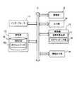
- FIG. 1is a schematic configuration of the driving support system according to the present embodiment.
- the driver assistance systemincludes an in-vehicle device 1 that moves together with a moving vehicle, a lidar (Light Detection and Ranking) 2, a Laser Illuminated Detection And Ringing, 2, a gyro sensor 3, a vehicle speed sensor 4, and GPS reception. It has a machine 5.
- the on-board unit 1is electrically connected to the rider 2, the gyro sensor 3, the vehicle speed sensor 4, and the GPS receiver 5, and based on these outputs, the position of the vehicle on which the on-board unit 1 is provided (“own vehicle position”). Also called.) Is estimated. Then, the in-vehicle device 1 performs automatic driving control of the vehicle and the like so as to travel along the set route to the destination based on the estimation result of the position of the own vehicle.
- the vehicle-mounted device 1stores a map database (DB: DataBase) 10 including voxel data “VD”.
- the voxel data VDis data in which position information and the like of a stationary structure are recorded for each voxel showing a cube (normal grid) which is the smallest unit in a three-dimensional space.
- the voxel data VDincludes data representing the measured point cloud data of the stationary structures in each voxel by a normal distribution, and is used for scan matching using NDT (Normal Distributions Transfer) as described later. Further, the in-vehicle device 1 estimates the position and yaw angle of the vehicle on the plane by NDT scan matching, and estimates the height position of the vehicle and at least one of the pitch angle and the roll angle based on the voxel data VD. ..
- the rider 2emits a pulsed laser to a predetermined angle range in the horizontal and vertical directions to discretely measure the distance to an object existing in the outside world, and a three-dimensional point indicating the position of the object. Generate group information.
- the rider 2has an irradiation unit that irradiates the laser light while changing the irradiation direction, a light receiving unit that receives the reflected light (scattered light) of the irradiated laser light, and scan data based on the light receiving signal output by the light receiving unit. It has an output unit that outputs.
- the scan datais generated based on the irradiation direction corresponding to the laser beam received by the light receiving unit and the response delay time of the laser beam specified based on the above-mentioned received signal.
- the shorter the distance to the objectthe higher the accuracy of the rider's distance measurement value, and the farther the distance, the lower the accuracy.
- the rider 2, the gyro sensor 3, the vehicle speed sensor 4, and the GPS receiver 5each supply output data to the vehicle-mounted device 1.
- the on-board unit 1is an example of the "information processing device” in the present invention
- the rider 2is an example of the "measurement unit” in the present invention.
- the driver assistance systemmay have an inertial measurement unit (IMU) for measuring the acceleration and the angular velocity of the measurement vehicle in the three axial directions in place of or in addition to the gyro sensor 3.
- IMUinertial measurement unit
- FIG. 2is a block diagram showing a functional configuration of the vehicle-mounted device 1.
- the vehicle-mounted device 1mainly includes an interface 11, a storage unit 12, a communication unit 13, an input unit 14, a control unit 15, and an information output unit 16. Each of these elements is connected to each other via a bus line.
- the interface 11acquires output data from sensors such as the rider 2, the gyro sensor 3, the vehicle speed sensor 4, and the GPS receiver 5, and supplies the output data to the control unit 15. Further, the interface 11 supplies a signal related to the traveling control of the vehicle generated by the control unit 15 to the electronic control unit (ECU: Electronic Control Unit) of the vehicle.
- ECUElectronic Control Unit
- the storage unit 12stores a program executed by the control unit 15 and information necessary for the control unit 15 to execute a predetermined process.
- the storage unit 12stores the map DB 10 including the voxel data VD.
- the map DB 10may be updated periodically.
- the control unit 15receives the partial map information regarding the area to which the own vehicle position belongs from the server device that manages the map information via the communication unit 13, and reflects it in the map DB 10.
- the storage unit 12does not have to store the map DB 10.
- the control unit 15communicates with the server device that stores the map data including the voxel data VD via the communication unit 13 to obtain the information necessary for the own vehicle position estimation process and the like at the required timing. To get by.
- the input unit 14is a button, a touch panel, a remote controller, a voice input device, etc. for the user to operate, and receives an input for designating a destination for route search, an input for designating on / off of automatic operation, and the like. ..
- the information output unit 16is, for example, a display, a speaker, or the like that outputs under the control of the control unit 15.
- the control unit 15controls the entire vehicle-mounted device 1 including a CPU that executes a program.
- the control unit 15has a posture angle calculation unit 17 and an NDT matching unit 18.
- the control unit 15is an example of the "extraction unit”, the "normal vector calculation unit”, the “angle calculation unit”, the “position estimation unit”, the “height calculation unit”, and the "computer” that executes the program in the present invention. is there.
- the posture angle calculation unit 17refers to the voxel data VD and calculates at least one of the pitch angle and the roll angle of the vehicle.
- the NDT matching unit 18performs scan matching based on NDT (NDT scan matching) based on the point cloud data output from the rider 2 and the voxel data VD corresponding to the voxel to which the point cloud data belongs. Estimate the vehicle position. In this embodiment, as will be described later, the NDT matching unit 18 estimates the plane position (that is, the position on the horizontal plane specified by the latitude and longitude) and the yaw angle (that is, the direction) of the vehicle in the NDT scan matching. Set as.
- FIG. 3is a diagram showing the position of the own vehicle to be estimated by the NDT matching unit 18 in two-dimensional Cartesian coordinates.
- the position of the own vehicle on the plane defined on the two-dimensional Cartesian coordinates of xyis represented by the coordinates "(x, y)" and the direction (yaw angle) " ⁇ " of the own vehicle. ..
- the yaw angle ⁇is defined as the angle formed by the traveling direction of the vehicle and the x-axis.
- the coordinates (x, y)are world coordinates indicating, for example, an absolute position corresponding to a combination of latitude and longitude, or a position with a predetermined point as the origin.
- the NDT matching unit 18estimates the position of the own vehicle using these x, y, and ⁇ as estimation parameters.
- the method of estimating the pitch angle and roll angle of the vehiclewill be described in detail in the section "(4) Estimating the attitude angle".
- the voxel data VDincludes data representing the measured point cloud data of the stationary structure in each voxel by a normal distribution.
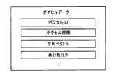
- FIG. 4shows an example of a schematic data structure of voxel data VD.
- the voxel data VDincludes information on parameters when the point cloud in the voxel is represented by a normal distribution.
- the voxel ID, voxel coordinates, average vector, and covarianceare included. Including with a matrix.
- Voxel coordinatesindicate the absolute three-dimensional coordinates of a reference position such as the center position of each voxel. Since each voxel is a cube in which the space is divided in a grid pattern and the shape and size are predetermined, it is possible to specify the space of each voxel by the voxel coordinates. The voxel coordinates may be used as the voxel ID.
- the "mean vector” and “covariance matrix”indicate the mean vector and covariance matrix corresponding to the parameters when the point cloud in the target voxel is represented by a normal distribution.
- the mean vector " ⁇ n " and covariance matrix "V n " in voxel nare given by the following equations (1) and (V), respectively. It is represented by 2).
- X L (j)[ x n (j) , Y n (j), z n (j)] T
- the on-board unit 1includes the point cloud data converted into an absolute coordinate system (also referred to as “world coordinate system”) which is the same coordinate system as the map DB 10, and the average vector ⁇ n included in the voxel data VD.
- the evaluation function value of the voxel n(also referred to as "individual evaluation function value”.) is calculated "E n".
- the vehicle-mounted device 1is based on the following equation (5) to calculate the individual evaluation function value E n of the voxel n.
- the in-vehicle device 1has a comprehensive evaluation function value (also referred to as “comprehensive evaluation function value”) “E (k) for all voxels to be matched, which is represented by the following equation (6). ) ”Is calculated.
- a comprehensive evaluation function valuealso referred to as “comprehensive evaluation function value”
- the vehicle-mounted device 1calculates the estimation parameter P that maximizes the comprehensive evaluation function value E (k) by an arbitrary root-finding algorithm such as Newton's method. Then, the on-board unit 1 is highly accurate by using the following equation (7) by applying the estimation parameter P to the predicted own vehicle position “X ⁇ (k)” provisionally calculated by dead reckoning. The estimated vehicle position "X ⁇ (k)" is calculated.
- the state variable vector indicating the position of the own vehicle at the reference time (that is, the current time) “k” to be calculatedis expressed as “X ⁇ (k)” or “X ⁇ (k)”. ..
- FIG. 5is an example of the functional block of the NDT matching unit 18.
- the NDT matching unit 18includes a dead reckoning block 21, a position prediction block 22, a coordinate conversion block 23, a point cloud data association block 24, and a position correction block 25.
- the dead reckoning block 21uses the moving speed and angular velocity of the vehicle based on the outputs of the gyro sensor 3, the vehicle speed sensor 4, the GPS receiver 5, and the like, and obtains the moving distance and the directional change from the previous time.
- the position prediction block 22adds the obtained movement distance and directional change to the estimated vehicle position X ⁇ (k-1) at time k-1 calculated in the immediately preceding measurement update step, and predicts the time k. vehicle position X - to calculate the (k).
- the coordinate conversion block 23converts the point cloud data output from the rider 2 into a world coordinate system which is the same coordinate system as the map DB 10.
- the coordinate conversion block 23has the predicted own vehicle position (that is, the plane position and orientation of the vehicle) output by the position prediction block 22 at time k, and the height and attitude of the vehicle output by the posture angle calculation unit 17 at time k. Based on the angle (here, at least one of the pitch angle and the roll angle), the coordinate conversion of the point cloud data output by the rider 2 is performed at time k. The details of this coordinate transformation will be described later.
- the point cloud data association block 24collates the point cloud data of the world coordinate system output by the coordinate conversion block 23 with the voxel data VD represented by the same world coordinate system to obtain the point cloud data and the voxels. Make a mapping.
- the position correction block 25calculates the individual evaluation function value based on the equation (5) for each voxel associated with the point cloud data, and the comprehensive evaluation function value E (k) based on the equation (6) is calculated.
- the estimated parameter P that becomes the maximumis calculated.
- the position correction block 25applies the estimation parameter P obtained at the time k to the predicted vehicle position X ⁇ (k) output by the position prediction block 22 to estimate itself. Calculate the vehicle position X ⁇ (k).
- the posture angle calculation unit 17refers to the voxel data VD, and the vehicle plane position x, y (that is, the vehicle plane position x, y (that is,) predicted or estimated by the NDT matching unit 18 from the voxel corresponding to the road surface of the road (also referred to as “road surface voxel”). (x -, y -) or (x ⁇ , y ⁇ )) to explore the road surface voxels located.
- the posture angle calculation unit 17includes voxel data VDs corresponding to "n" peripheral road surface voxels including the road surface voxels in which the vehicle plane positions x and y are located (also referred to as “vehicle position road surface voxels").
- “N”is any integer greater than or equal to 3.
- the vehicle-positioned road surface voxelsare an example of the "first unit region” in the present invention, and the n-1 peripheral road surface voxels other than the vehicle-positioned road surface voxels are the "second unit region” in the present invention. This is an example.
- FIG. 6Ais a bird's-eye view showing the correspondence between the position of the vehicle and the road surface voxels.
- "Vo1" to "Vo4" and “Vo6" to “Vo9”are shown.
- the attitude angle calculation unit 17is based on the information of the voxel coordinates and the average vector included in the voxel data VD corresponding to each of the n road surface voxels, and the world coordinates of the road surface included in each of the n road surface boxels. Calculate the average vector (also called “road surface average vector") in the system.
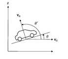
- FIG. 6Bis a side view of the vehicle in which the road surface average vector for each road surface voxel is clearly shown.
- the posture angle calculation unit 17regards the road surface as a plane, and expresses the equation of a plane that approximates the road surface by the following equation (8).
- the posture angle calculation unit 17calculates n road surface average vectors (x 1 , y 1 , z 1 ), (x 2 , y 2 , z 2 ), ..., (X n , y n , z n). ) Is substituted into the equation (8) to obtain a simultaneous equation consisting of n equations shown in the equation (9).
- Equation ( 10)is represented by the following equation (11).
- the attitude angle calculation unit 17determines the vehicle orientation vector “Vx” on the xy plane based on the yaw angle predicted or estimated by the NDT matching unit 18.
- FIG. 7is an xy plan view showing the relationship between the yaw angle of the vehicle (here, ⁇ ⁇ ) and the traveling direction vector Vx. Since the z component of the traveling direction vector Vx is 0, and the x component and the y component are proportional to the cosine and sine of the yaw angle of the vehicle, respectively, the traveling direction vector Vx is calculated by the following equation (16). Given.
- the angle " ⁇ '" formed by the normal vector Vn and the traveling direction vector Vxis represented by the following equation (17) including the inner product calculation of the normal vector Vn and the traveling direction vector Vx.
- the attitude angle calculation unit 17calculates the pitch angle “ ⁇ ” of the vehicle based on the angle ⁇ ′ formed by the normal vector Vn and the traveling direction vector Vx.
- FIG. 8is a diagram showing the relationship between the angle ⁇ ′ formed by the normal vector Vn and the traveling direction vector Vx and the pitch angle ⁇ of the vehicle.
- the angle ⁇ 'formed by the normal vector Vn and the traveling direction vector Vxis 90 degrees (that is, ⁇ / 2) larger than the pitch angle ⁇ of the vehicle.
- the posture angle calculation unit 17calculates the pitch angle ⁇ based on the following equation (18).
- the attitude angle calculation unit 17is based on the coefficient vector of the plane equation calculated from the n road surface average vectors based on the voxel data VD of the road surface voxel and the yaw angle predicted or estimated by the NDT matching unit 18.
- the pitch angle of the vehiclecan be preferably calculated.
- the posture angle calculation unit 17calculates the normal vector Vn shown in the equation (15) based on the n road surface average vectors based on the voxel data VD in the same manner as the calculation of the pitch angle. To do.
- FIG. 9is an xy plan view showing the relationship between the yaw angle of the vehicle (here, ⁇ ⁇ ) and the lateral vector V Y.
- the lateral vector V Yrotates the yaw angle (here, ⁇ ⁇ ) predicted or estimated by the NDT matching unit 18 by 90 degrees ( ⁇ / 2) along the xy plane.
- the lateral vector V Yis given by the following equation (19).
- the angle between the normal vector Vn and lateral vector V Y "phi ''is illustrated by the following equations including the inner product computation of the normal vector Vn and the transverse direction vector V Y (20).
- the attitude angle calculation unit 17calculates the roll angle “ ⁇ ” of the vehicle based on the angle ⁇ ′ formed by the normal vector Vn and the lateral vector V Y.
- FIG. 10is a diagram showing the relationship between the angle ⁇ 'formed by the normal vector Vn and the lateral vector V Y and the roll angle ⁇ of the vehicle.
- the angle ⁇ 'formed by the normal vector Vn and the lateral vector V Yis 90 degrees (that is, ⁇ / 2) larger than the roll angle ⁇ of the vehicle.
- the posture angle calculation unit 17calculates the roll angle ⁇ based on the following equation (21).
- the attitude angle calculation unit 17preferably bases the vehicle on the coefficient vector of the plane equation calculated from the n road surface average vectors based on the voxel data VD and the yaw angle predicted or estimated by the NDT matching unit 18. Roll angle can be calculated.
- the coordinate conversion block 23 of the NDT matching unit 18uses the pitch angle ⁇ calculated by the posture angle calculation unit 17 to generate the rotation matrix “R ⁇ ” shown in the following equation (22).
- the coordinate conversion block 23performs coordinate conversion of the point cloud data relating to the pitch angle ⁇ by the following equation (24).
- coordinate transformation block 23with respect to n number of three-dimensional data corresponding to each row of X L 'of formula (24), the value of the predicted or estimated three-dimensional vehicle position (x, y, z) Is added.
- point cloud data converted into the world coordinate systemis also generated for the three-dimensional positions of x, y, and z.
- the coordinate conversion block 23supplies the point cloud data converted into the world coordinate system to the point cloud data association block 24.
- the coordinate conversion block 23uses the rotation matrix R ⁇ based on the pitch angle ⁇ calculated by the attitude angle calculation unit 17 and the rotation matrix “R ⁇ ” based on the roll angle ⁇ , and n 3 output by the rider 2.
- the rotation matrix "R”to be multiplied by the matrix X L indicating the dimension data, created based on the following equation (25).
- the position prediction block 22performs coordinate conversion of the point cloud data regarding the pitch angle ⁇ and the roll angle ⁇ into the world coordinate system by the following equation (26).
- coordinate transformation block 23by multiplying relative X L 'of formula (26) as well the rotation matrix based on the yaw angle [psi, performs coordinate conversion to the world coordinate system of the point cloud data about the yaw angle [psi.
- the coordinate conversion block 23supplies the point cloud data converted into the world coordinate system by the above processing to the point cloud data association block 24.
- the coordinate conversion block 23further performs a process of converting point cloud data indicating each of the three-dimensional positions based on the combination of the distance and the scan angle measured by the rider 2 into the vehicle coordinate system. You may go.
- the vehicle coordinate systemis a vehicle coordinate system centered on the traveling direction and the lateral direction of the vehicle.
- the coordinate conversion block 23converts the point cloud data from the coordinate system based on the rider 2 to the vehicle coordinate system based on the information of the installation position and the installation angle of the rider 2 with respect to the vehicle, and converts the point cloud data into the vehicle coordinate system.
- the point cloud datais further converted into the world coordinate system by the method described above.
- the process of converting the point cloud data output by the rider installed in the vehicle into the vehicle coordinate systemis disclosed in, for example, the international publication WO2019 / 188745.
- the coordinate conversion block 23may perform coordinate conversion in consideration of only the roll angle ⁇ among the pitch angle ⁇ and the roll angle ⁇ .
- coordinate transformation block 23the rotation matrix R phi represented by the formula (25) may be multiplied by a matrix X L indicating the n pieces of three-dimensional data rider 2 outputs.
- FIG. 11Ais a side view of a vehicle traveling on a flat road surface and a road.
- the vehicle height "z ⁇ " from the reference position of the world coordinate systemis the height from the reference position of the world coordinate system to the road surface, and the height of the vehicle from the road surface. (Also referred to as “vehicle reference position z 0 ") is added to the height.
- the height "d" from the vehicle of a certain measurement point "Ptag1" measured by the rider 2is added to the vehicle height z ⁇
- “z ⁇ + d"is the actual height of the measurement point Ptag1 in the world coordinate system.
- MatchTherefore, in this case, in the mapping process executed by the point cloud data mapping block 24, the target measurement point Ptag1 is associated with the voxel “V1” that actually includes the measurement point Ptag1.
- FIG. 11Bis a side view of a vehicle and a road traveling on a road surface having a large slope when the point cloud data is not subjected to coordinate conversion based on the pitch angle of the vehicle.
- the point cloud datais upward because the pitch angle is generated in the vehicle due to the road surface gradient. Therefore, the height of the measurement point "Ptag2" existing at the position of the height d from the vehicle in the world coordinate system is not "z ⁇ + d" obtained by adding the height d to the vehicle height z ⁇ .
- the height of the measurement point Ptag2 in the world coordinate systemis calculated as "z ⁇ + d", so that the measurement point Ptag2 actually exists.
- the associationis not made with the voxel "V2", and the association is erroneously made with the voxel "V2 ⁇ ".
- FIG. 12is a side view of a vehicle and a road traveling on a road surface having a large slope when coordinate conversion is performed on the point cloud data based on the pitch angle of the vehicle based on this embodiment.
- the point cloud data output by the rider 2is converted into the world coordinate system in consideration of the pitch angle of the vehicle by the rotation matrix using the pitch angle obtained by the calculation method based on the embodiment. Therefore, in this case, the height of the measurement point "Ptag3" existing at the height d from the vehicle in the world coordinate system is "z ⁇ + d". Therefore, in the mapping process executed by the point cloud data mapping block 24, the measurement point Ptag3 is associated with the voxel “V3” (that is, the correct matching target) in which the measurement point Ptag3 actually exists. NDT scan matching is preferably performed.
- the on-board unit 1performs coordinate conversion based on the roll angle of the vehicle on the point cloud data, so that each measurement point of the point cloud data output by the rider 2 is performed. Can be appropriately associated with the voxel that is the correct matching target.
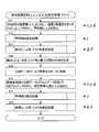
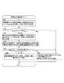
- FIG. 13is an example of a flowchart showing a procedure of vehicle position / orientation estimation processing.
- the posture angle calculation unit 17 and the NDT matching unit 18 of the vehicle-mounted device 1repeatedly execute the processing of the flowchart shown in FIG. 13 at predetermined time intervals for estimating the position and posture of the vehicle.
- the symbols displayed to the right of each step in FIG. 13represent the elements calculated in each step.
- the dead reckoning block 21 of the NDT matching unit 18uses the moving speed and angular velocity of the vehicle based on the outputs of the gyro sensor 3, the vehicle speed sensor 4, the GPS receiver 5, etc., to change the moving distance and direction from the previous time. Ask for.
- the position prediction block 22 of the NDT matching unit 18is calculated from the estimated vehicle position x ⁇ , y ⁇ , and ⁇ ⁇ obtained one time before (the processing time immediately before), and the predicted vehicle position x ⁇ at the current time. , Y ⁇ , ⁇ ⁇ are calculated (step S11).
- the attitude angle calculation unit 17by performing the estimation processing of the vehicle height (e.g. altitude where the vehicle is located), the predicted vehicle height "z -" is calculated (step S12). This process will be described later with reference to FIG. Further, the posture angle calculation unit 17 calculates the predicted roll angle “ ⁇ ⁇ ” and the predicted pitch angle “ ⁇ ⁇ ” by estimating the roll angle / pitch angle of the vehicle (step S13). This process will be described later with reference to FIG.
- the coordinate conversion block 23 of the NDT matching unit 18generates a rotation matrix R (see equation (25)) based on the roll angle and pitch angle calculated in step S13 (step S14). Then, the coordinate conversion block 23 converts the point cloud data into the data of the world coordinate system (step S15). After that, the NDT matching unit 18 (point cloud data association block 24 and position correction block 25) performs NDT matching using the point cloud data after coordinate conversion and the voxel data VD, and estimates the vehicle position at the current time. Calculate x ⁇ , y ⁇ , and ⁇ ⁇ (step S16).
- the attitude angle calculation unit 17estimates by performing the same vehicle height estimation process as in step S12 again using the estimated own vehicle positions x ⁇ , y ⁇ , and ⁇ ⁇ at the calculated current time.
- the vehicle height "z ⁇ "is calculated (step S17). This process will be described later with reference to FIG.
- the posture angle calculation unit 17uses the estimated vehicle positions x ⁇ , y ⁇ , ⁇ ⁇ and the estimated vehicle height z ⁇ at the calculated current time to estimate the roll angle and pitch angle of the vehicle.
- the estimated roll angle “ ⁇ ⁇ ” and the estimated pitch angle “ ⁇ ⁇ ”are calculated (step S18). This process will be described later with reference to FIG.
- FIG. 14is an example of a flowchart showing a procedure of the vehicle height estimation process executed in steps S12 and S17 of FIG.
- the attitude angle calculation unit 17determines the vehicle position road surface boxel based on the predicted or estimated plane position of the vehicle, and at the same time, the vehicle reference position is set to the z coordinate of the average vector of the vehicle position road surface boxel. The value obtained by adding z 0 (the height of the vehicle from the road surface) is determined as the vehicle height to be obtained.
- the on-board unit 1sets the voxel index idz of the vehicle-positioned road surface voxel, which has low reliability as the vehicle-positioned road surface voxel, to "-1" so that it is not used in the roll angle / pitch angle estimation processing described later. Label.
- the attitude angle calculation unit 17acquires the boxel index (idx, idy) of the boxel including the predicted vehicle position x ⁇ , y ⁇ or the estimated vehicle position x ⁇ , y ⁇ , and the boxel index (idx, idy). ) Is searched for (step S21). That is, the posture angle calculation unit 17 refers to the voxel data VD and sets the voxels that are the same positions in the predicted own vehicle position x ⁇ , y ⁇ or the estimated own vehicle positions x ⁇ , y ⁇ and the xy plane in the height direction. Explore. In the case of step S12 of FIG.
- the posture angle calculation unit 17searches for a box cell having a box cell index (idx, idy) including the predicted own vehicle positions x ⁇ and y ⁇ . Further, in the case of step S17 of FIG. 13, the posture angle calculation unit 17 searches for a voxel having a voxel index (idx, idy) including the estimated vehicle positions x ⁇ and y ⁇ .
- the posture angle calculation unit 17determines whether or not one or more voxels have been detected in step S21 (step S22). Then, when the voxel is not detected (step S22; No), the posture angle calculation unit 17 obtains the predicted vehicle height z ⁇ or the estimated vehicle height z ⁇ one hour before, and the predicted vehicle height z ⁇ to be obtained. Alternatively, it is determined as the estimated vehicle height z ⁇ (step S27). Further, in step S27, the posture angle calculation unit 17 determines a temporary vehicle position road surface voxel at which the voxel index idz is “-1”.
- step S21when one or more voxels are detected in step S21 (step S22; Yes), the attitude angle calculation unit 17 sets the detected voxels as candidates for the vehicle position road surface voxels, and z-coordinates of each candidate (corresponding to the above).
- the z-coordinate of the candidate average vector)is read from the voxel data VD, and the vehicle reference position z 0 is added to each z-coordinate (step S23).
- the vehicle reference position z 0is stored in advance in, for example, the storage unit 12.
- the value obtained by adding the vehicle reference position z 0 to the z coordinate of the average vector of each candidateis the value closest to the predicted vehicle height z ⁇ or the estimated vehicle height z ⁇ one hour ago.
- Candidates for the vehicle position road surface voxels to be usedare selected as the vehicle position road surface voxels (step S24).
- the posture angle calculation unit 17adds the value obtained by adding the vehicle reference position z 0 to the z coordinate of the average vector of the selected own vehicle position road surface boxel, and the predicted vehicle height z ⁇ or the estimated vehicle height z one hour ago.
- the difference from ⁇is equal to or less than a predetermined value (step S25; Yes)
- the predetermined valueis set to, for example, the upper limit of the fluctuation range of the height at which the vehicle can occur on a slope or the like within the time interval from one hour before to the current time.
- the posture angle calculation unit 17determines a value obtained by adding the vehicle reference position z 0 to the z coordinate of the average vector of the vehicle position road surface voxel as the predicted vehicle height z ⁇ or the estimated vehicle height z ⁇ to be obtained (Ste S26).
- the posture angle calculation unit 17should obtain the predicted vehicle height z ⁇ or the estimated vehicle height z ⁇ one time ago. It is defined as z ⁇ or the estimated vehicle height z ⁇ (step S27). Further, in step S27, the posture angle calculation unit 17 sets the voxel index idz of the vehicle position road surface voxel selected in step S24 to “-1”.
- FIG. 15is an example of a flowchart showing a procedure for estimating the roll angle / pitch angle of the vehicle executed in steps S13 and S18 of FIG.
- the vehicle-mounted device 1estimates both the roll angle and the pitch angle of the vehicle as an example, but even if a process of estimating only one of the roll angle and the pitch angle of the vehicle is performed. Good.
- the posture angle calculation unit 17refers to the voxel indexes (idx, idy, idz) of the vehicle position road surface voxels determined by the vehicle height estimation process in step S12 or step S17 executed immediately before (step S31). Then, the posture angle calculation unit 17 determines whether or not the voxel index idz of the vehicle position road surface voxel is set to "-1" (step S32). When the voxel index idz of the vehicle position road surface voxel is "-1" (step S32; Yes), the posture angle calculation unit 17 has low reliability of the target vehicle position road surface voxel or the vehicle position road surface voxel. Is determined that could not be detected.
- the posture angle calculation unit 17obtains the roll angle ⁇ ( ⁇ ⁇ or ⁇ ⁇ ) or the pitch angle ⁇ ( ⁇ ⁇ or ⁇ ⁇ ) calculated one hour before, and the roll angle ⁇ at the current time to be obtained. It is defined as ( ⁇ ⁇ or ⁇ ⁇ ) or the pitch angle ⁇ ( ⁇ ⁇ or ⁇ ⁇ ) (step S38).
- the posture angle calculation unit 17is in the vicinity of the own vehicle position road surface voxel including the own vehicle position road surface voxel.
- the voxel data VD of n voxels of the aboveis acquired (step S33).
- the posture angle calculation unit 17describes a voxel in which at least one of the vehicle position road surface voxels and the voxel indexes idx and idy is different and the voxel index idz is the same or 1 different, together with the vehicle position road surface voxels. Considered as n voxels.
- the posture angle calculation unit 17reads the x, y, and z coordinates of the average vector included in each voxel data VD for the above-mentioned n voxels, and thereby, the matrix C and the vector b according to the equation (10). Is created (step S34). Next, the posture angle calculation unit 17 calculates the coefficient vector a by the least squares method based on the equation (13), and specifies the normal vector Vn shown in the equation (15) (step S35). Then, the attitude angle calculation unit 17 uses the predicted or estimated yaw angle (direction) ⁇ ( ⁇ ⁇ or ⁇ ⁇ ) of the vehicle, and uses the traveling direction vector Vx shown in the equation (16) and the equation (19).
- the indicated lateral vector V Yis calculated (step S36).
- the attitude angle calculation unit 17calculates the inner product of the normal vector Vn and the traveling direction vector Vx based on the equation (17), and calculates the inner product of the normal vector Vn and the lateral vector V Y based on the equation (20).
- the roll angle ⁇ ( ⁇ ⁇ or ⁇ ⁇ ) or the pitch angle ⁇ ( ⁇ ⁇ or ⁇ ⁇ ) at the current time to be calculatedis calculated (step S37).
- FIGS. 17A to 17Eshow the number of point cloud data, the number of associations, the association ratio, the evaluation value, and the pitch angle obtained on the road described above when the pitch angle is not estimated. Each is shown.
- the "number of point cloud data”indicates the number of measurement points of the point cloud data obtained from the rider for each processing time
- the "number of associations”indicates the number of associations with the voxels among the number of point cloud data. Shows the number of measurement points created.
- the "correspondence ratio”indicates the ratio of the number of associations to the number of point cloud data
- the “evaluation value”indicates the comprehensive evaluation function value corresponding to the estimation parameter determined in the NDT scan matching.
- “Pitch angle”indicates the pitch angle of the vehicle estimated by the vehicle. Since the pitch angle is not estimated in the cases of FIGS. 17 (A) to 17 (E), the pitch angle shown in FIG. 17 (E) is always 0 degrees.
- the absolute value of the pitch angleis temporarily increased in the period indicated by the broken line frame 60 and the broken line frame 61, which corresponds to the period in which the vehicle is traveling on a slope. Even during the traveling period of such a slope, as shown in FIG. 16C, the association ratio is suppressed from the decrease in the number of associations by the coordinate conversion of the point cloud data in consideration of the pitch angle, and other The association ratio is the same as the running period of a flat road.
- the association ratio corresponding to the period corresponding to the above-mentioned running period of the slopeis the broken line frame 70 in FIG. 17 (C) and the association ratio.
- the decreaseis temporarily significant. If the number of associations and the association ratio are reduced, it is presumed that the robustness of NDT scan matching is reduced and the reliability of the estimated own vehicle position is low.
- the pitch angle and converting the coordinates of the point cloud data based on the pitch angleit is preferable to reduce the number of points cloud data associated and the association ratio even on a slope. It can be suppressed and the robustness of own vehicle position estimation by NDT scan matching can be suitably improved.
- the roll angle and transforming the coordinates of the point cloud data based on the roll angleit is possible to preferably suppress a decrease in the number of point cloud data associated and the association ratio even on a road with a high cross slope, and NDT.
- the robustness of own vehicle position estimation by scan matchingcan be suitably improved.
- the control unit 15 of the vehicle-mounted device 1has a plurality of control units 15 existing in the vicinity of the own vehicle from the voxel data VD which is the position information of the object for each unit area (voxel) dividing the space.
- the voxel data VD of the voxel ofis extracted.
- the control unit 15calculates a normal vector with respect to the approximate plane obtained based on the voxel data VD of the extracted voxels.
- the control unit 15calculates at least one of the pitch angle and the roll angle of the own vehicle based on the direction of the own vehicle and the normal vector.
- the vehicle-mounted device 1can calculate at least one of the pitch angle and the roll angle with high accuracy based on the voxel data VD.
- the vehicle-mounted device 1calculates the vehicle height (predicted vehicle height z ⁇ or estimated vehicle height z ⁇ ) by performing the vehicle height estimation process shown in FIG.
- the method of calculating the height of the vehicleis not limited to this.
- the vehicle-mounted device 1may further add the height of the vehicle as an estimation parameter in the own vehicle position estimation based on NDT scan matching.
- the in-vehicle device 1has four variables (x, y, z,) in consideration of the coordinates (x, y) and the yaw angle ⁇ shown in FIG. 3, as well as the coordinates of the x-axis and the z-axis perpendicular to the y-axis.
- the vehicle positionis estimated with ⁇ ) as the state variable of the vehicle position.
- the vehicle-mounted device 1can suitably estimate the height of the vehicle.
- the vehicle-mounted device 1may estimate at least one of the pitch angle and the roll angle of the vehicle based on the embodiment even when NDT scan matching is not performed.
- the vehicle-mounted device 1repeatedly estimates at least one of the pitch angle and the roll angle of the vehicle based on the voxel data VD by repeatedly executing steps S11 to S13.
- the on-board unit 1uses the estimated pitch angle and / and roll angle for various applications such as coordinate conversion of output data of an external sensor such as a rider 2 or slope (bank) detection processing. It is possible.
- the configuration of the driving support system shown in FIG. 1is an example, and the configuration of the driving support system to which the present invention is applicable is not limited to the configuration shown in FIG.
- the electronic control device of the vehicleinstead of having the vehicle-mounted device 1, the electronic control device of the vehicle may execute the processing of the posture angle calculation unit 17 and the NDT matching unit 18 of the vehicle-mounted device 1.
- the map DB 10is stored in, for example, a storage unit in the vehicle or a server device that performs data communication with the vehicle, and the electronic control device of the vehicle can refer to the map DB 10 to determine the roll angle and / and the pitch angle. Execute estimation and own vehicle position estimation based on NDT scan matching.
- the voxel data VDis not limited to a data structure including an average vector and a covariance matrix.
- the voxel data VDmay include the point cloud data measured by the measurement maintenance vehicle used when calculating the average vector and the covariance matrix as it is.
- the vehicle-mounted device 1generates the matrix C represented by the equation (10) by, for example, referring to the voxel data VD and calculating the average vector for each voxel.
- this embodimentis not limited to scan matching by NDT, and other scan matching such as ICP (Iterative Closet Point) may be applied. Even in this case, as in the embodiment, the vehicle-mounted device 1 calculates the posture angle (pitch angle or / and roll angle) based on the embodiment, and also performs arbitrary scan matching to the own vehicle with respect to the plane position and orientation. Perform position estimation.
- posture anglepitch angle or / and roll angle
Landscapes
- Engineering & Computer Science (AREA)
- Radar, Positioning & Navigation (AREA)
- Remote Sensing (AREA)
- Physics & Mathematics (AREA)
- General Physics & Mathematics (AREA)
- Electromagnetism (AREA)
- Computer Networks & Wireless Communication (AREA)
- Automation & Control Theory (AREA)
- Databases & Information Systems (AREA)
- Navigation (AREA)
Abstract
Description
Translated fromJapanese本発明は、車両の姿勢の推定技術に関する。The present invention relates to a technique for estimating the posture of a vehicle.
従来から、レーザスキャナなどの計測装置を用いて計測した周辺物体の形状データを、予め周辺物体の形状が記憶された地図情報と照合(マッチング)することで、車両の自己位置を推定する技術が知られている。例えば、特許文献1には、空間を所定の規則で分割したボクセル中における検出物が静止物か移動物かを判定し、静止物が存在するボクセルを対象として地図情報と計測データとのマッチングを行う自律移動システムが開示されている。また、特許文献2には、ボクセル毎の静止物体の平均ベクトルと共分散行列とを含むボクセルデータとライダが出力する点群データとの照合により自車位置推定を行うスキャンマッチング手法が開示されている。Conventionally, a technique for estimating the self-position of a vehicle by collating (matching) the shape data of a peripheral object measured using a measuring device such as a laser scanner with map information in which the shape of the peripheral object is stored in advance has been used. Are known. For example, in
一般に、車両は道路面に拘束されており、車両のピッチ角やロール角や上下方向の変化は、サスペンションによる変動はあるものの無視できる程度に小さい。よって、一般的なスキャンマッチングによる車両の自己位置推定では、車両の平面位置及び方位を推定すべきパラメータとして設定している。一方、勾配が大きい坂道や横断勾配を含む道路などの走行時では、車両の平面位置及び方位を推定するだけでは、ピッチ角やロール角の変化に対応できず、マッチングされるべきボクセルと計測データとの対応付けがされなかったり、間違った対応付けが行われてしまったりする。ここで、ピッチ角やロール角の変化に対応するため、ピッチ角やロール角を自己位置推定の推定パラメータとして加えた場合、推定パラメータの増加に起因して計算負荷が増加し、必要な周期での自己位置推定が安定的に終わらなくなるという問題が生じる。また、IMU(Inertial Measurement Unit)のデータから車両のピッチ角やロール角を求める方法が存在するが、一般的なIMUでは感度誤差やオフセットがあるために、ピッチ角やロール角を正確に計算できないという問題もあった。Generally, the vehicle is restrained on the road surface, and changes in the pitch angle, roll angle, and vertical direction of the vehicle are negligibly small, although there are fluctuations due to the suspension. Therefore, in the self-position estimation of the vehicle by general scan matching, the plane position and orientation of the vehicle are set as parameters to be estimated. On the other hand, when driving on a slope with a large slope or a road including a cross slope, it is not possible to respond to changes in the pitch angle and roll angle simply by estimating the plane position and orientation of the vehicle, and the voxels and measurement data to be matched. It may not be associated with, or it may be associated incorrectly. Here, when the pitch angle and roll angle are added as the estimation parameters for self-position estimation in order to respond to changes in the pitch angle and roll angle, the calculation load increases due to the increase in the estimation parameters, and the calculation load increases at the required cycle. The problem arises that the self-position estimation of is not completed stably. In addition, there is a method of obtaining the pitch angle and roll angle of the vehicle from the data of IMU (Inertial Measurement Unit), but the pitch angle and roll angle cannot be calculated accurately in a general IMU due to sensitivity error and offset. There was also a problem.
本発明は、上記のような課題を解決するためになされたものであり、車両の姿勢を好適に推定可能な情報処理装置を提供することを主な目的とする。The present invention has been made to solve the above problems, and an object of the present invention is to provide an information processing device capable of suitably estimating the posture of a vehicle.
請求項に記載の発明は、空間を区切った単位領域ごとの物体の位置情報から、移動体の近傍に存在する複数の単位領域での物体の位置情報を抽出する抽出部と、前記複数の単位領域での物体の位置情報に基づき求めた近似した平面に対する法線ベクトルを算出する法線ベクトル算出部と、前記移動体の向きと、前記法線ベクトルとに基づき、前記移動体のピッチ角又はロール角の少なくとも一方を算出する角度算出部と、を有する情報処理装置であることを特徴とする。The invention according to the claim is an extraction unit that extracts position information of an object in a plurality of unit areas existing in the vicinity of a moving body from the position information of an object for each unit area that divides a space, and the plurality of units. Based on the normal vector calculation unit that calculates the normal vector for the approximated plane obtained based on the position information of the object in the region, the direction of the moving body, and the normal vector, the pitch angle or the pitch angle of the moving body or It is an information processing apparatus having an angle calculation unit for calculating at least one of the roll angles.
また、請求項に記載の発明は、情報処理装置が実行する制御方法であって、空間を区切った単位領域ごとの物体の位置情報から、移動体の近傍に存在する複数の単位領域での物体の位置情報を抽出し、前記複数の単位領域での物体の位置情報に基づき求めた近似した平面に対する法線ベクトルを算出し、前記移動体の向きと、前記法線ベクトルとに基づき、前記移動体のピッチ角又はロール角の少なくとも一方を算出する制御方法であることを特徴とする。Further, the invention described in the claim is a control method executed by an information processing apparatus, and is an object in a plurality of unit areas existing in the vicinity of a moving body based on the position information of the object in each unit area dividing a space. The position information of the above is extracted, the normal vector with respect to the approximate plane obtained based on the position information of the object in the plurality of unit regions is calculated, and the movement is based on the direction of the moving body and the normal vector. It is a control method for calculating at least one of a body pitch angle and a roll angle.
また、請求項に記載の発明は、空間を区切った単位領域ごとの物体の位置情報から、移動体の近傍に存在する複数の単位領域での物体の位置情報を抽出する抽出部と、前記複数の単位領域での物体の位置情報に基づき求めた近似した平面に対する法線ベクトルを算出する法線ベクトル算出部と、前記移動体の向きと、前記法線ベクトルとに基づき、前記移動体のピッチ角又はロール角の少なくとも一方を算出する角度算出部としてコンピュータを機能させるプログラムであることを特徴とする。The invention according to the claim also includes an extraction unit that extracts position information of an object in a plurality of unit areas existing in the vicinity of a moving body from the position information of an object for each unit area that divides a space, and the plurality of extraction units. Based on the normal vector calculation unit that calculates the normal vector for the approximate plane obtained based on the position information of the object in the unit region of, the direction of the moving body, and the normal vector, the pitch of the moving body. It is a program that causes a computer to function as an angle calculation unit that calculates at least one of an angle or a roll angle.
本発明の好適な実施形態によれば、情報処理装置は、空間を区切った単位領域ごとの物体の位置情報から、移動体の近傍に存在する複数の単位領域での物体の位置情報を抽出する抽出部と、前記複数の単位領域での物体の位置情報に基づき求めた近似した平面に対する法線ベクトルを算出する法線ベクトル算出部と、前記移動体の向きと、前記法線ベクトルとに基づき、前記移動体のピッチ角又はロール角の少なくとも一方を算出する角度算出部と、を有する。According to a preferred embodiment of the present invention, the information processing apparatus extracts the position information of the object in a plurality of unit areas existing in the vicinity of the moving body from the position information of the object in each unit area dividing the space. Based on the extraction unit, the normal vector calculation unit that calculates the normal vector for the approximate plane obtained based on the position information of the object in the plurality of unit regions, the orientation of the moving body, and the normal vector. It has an angle calculation unit for calculating at least one of the pitch angle and the roll angle of the moving body.
一般に、移動体は路面上を走行するため、移動体の近傍には路面が存在し、移動体の近傍に存在する複数の単位領域には路面が含まれることが推測される。また、移動体は路面に拘束されており、路面の傾きに応じた移動体のピッチ角及びロール角が生じる。以上を勘案し、この態様では、情報処理装置は、路面の位置情報と推測される複数の単位領域での物体の位置情報に基づき路面を近似した平面の法線ベクトルを算出する。これにより、情報処理装置は、算出した法線ベクトルと移動体の向きとの関係に基づき、移動体のピッチ角又はロール角の少なくとも一方を好適に算出することができる。In general, since a moving body travels on a road surface, it is presumed that the road surface exists in the vicinity of the moving body, and that the road surface is included in a plurality of unit regions existing in the vicinity of the moving body. Further, the moving body is constrained by the road surface, and the pitch angle and the roll angle of the moving body are generated according to the inclination of the road surface. In consideration of the above, in this embodiment, the information processing apparatus calculates the normal vector of the plane that approximates the road surface based on the position information of the object in a plurality of unit regions presumed to be the position information of the road surface. Thereby, the information processing apparatus can preferably calculate at least one of the pitch angle and the roll angle of the moving body based on the relationship between the calculated normal vector and the orientation of the moving body.
上記情報処理装置の一態様では、前記角度算出部は、水平面上において前記移動体の進行方向の向きを示すベクトルと、前記法線ベクトルとの内積に基づき、前記ピッチ角を算出する。この態様により、情報処理装置は、移動体の水平面上での進行方向と近似平面の法線ベクトルとのなす角を算出し、移動体のピッチ角を好適に求めることができる。In one aspect of the information processing apparatus, the angle calculation unit calculates the pitch angle based on the inner product of the vector indicating the direction of the moving body in the traveling direction on the horizontal plane and the normal vector. According to this aspect, the information processing apparatus can calculate the angle formed by the traveling direction of the moving body on the horizontal plane and the normal vector of the approximate plane, and can preferably obtain the pitch angle of the moving body.
上記情報処理装置の他の一態様では、前記角度算出部は、水平面上において前記移動体の横方向の向きを示すベクトルと、前記法線ベクトルとの内積に基づき、前記ロール角を算出する。この態様により、情報処理装置は、移動体の水平面上での横方向と近似平面の法線ベクトルとのなす角を算出し、移動体のロール角を好適に求めることができる。In another aspect of the information processing apparatus, the angle calculation unit calculates the roll angle based on the inner product of a vector indicating the lateral direction of the moving body on a horizontal plane and the normal vector. According to this aspect, the information processing apparatus can calculate the angle formed by the horizontal direction of the moving body on the horizontal plane and the normal vector of the approximate plane, and can preferably obtain the roll angle of the moving body.
上記情報処理装置の他の一態様では、情報処理装置は、前記単位領域ごとに、前記物体の位置情報と、前記移動体に設けられた計測部が出力する計測データを前記ピッチ角又はロール角の少なくとも一方に基づき座標変換したデータと、の照合を行うことで、前記移動体の位置推定を行う位置推定部をさらに有する。この態様では、情報処理装置は、物体の位置情報と、計測部が出力する計測データとの照合(マッチング)により移動体の位置推定を行う。このとき、情報処理装置は、算出したピッチ角又はロール角に基づき計測データを座標変換する。これにより、情報処理装置は、坂道や横断勾配が高い道路上での走行により車両のピッチ角又はロール角の変化が生じた場合であっても、被計測対象が実際に存在する単位領域と当該被計測対象の計測データとを的確に対応付けてマッチングを行うことができる。In another aspect of the information processing device, the information processing device outputs the position information of the object and the measurement data output by the measurement unit provided on the moving body for each unit area, such as the pitch angle or the roll angle. Further has a position estimation unit that estimates the position of the moving body by collating with the data whose coordinates have been converted based on at least one of the above. In this aspect, the information processing device estimates the position of the moving body by collating (matching) the position information of the object with the measurement data output by the measuring unit. At this time, the information processing apparatus performs coordinate conversion of the measurement data based on the calculated pitch angle or roll angle. As a result, the information processing device can be used with the unit area in which the object to be measured actually exists even when the pitch angle or roll angle of the vehicle changes due to traveling on a slope or a road having a high cross slope. Matching can be performed by accurately associating with the measurement data of the object to be measured.
上記情報処理装置の他の一態様では、前記単位領域ごとの物体の位置情報は、前記単位領域ごとの当該物体の位置に関する平均ベクトルの情報を含み、前記法線ベクトル算出部は、前記複数の単位領域での各々の前記平均ベクトルの座標に基づき、前記法線ベクトルを算出する。この態様によれば、情報処理装置は、移動体が存在する路面の位置情報と推測される複数の単位領域での物体の位置情報に基づき、当該路面を近似した平面の法線ベクトルを好適に算出することができる。In another aspect of the information processing apparatus, the position information of the object for each unit area includes the information of the average vector regarding the position of the object for each unit area, and the normal vector calculation unit is a plurality of the above. The normal vector is calculated based on the coordinates of each of the average vectors in the unit region. According to this aspect, the information processing apparatus preferably obtains a normal vector of a plane that approximates the road surface based on the position information of the object in a plurality of unit regions presumed to be the position information of the road surface on which the moving body exists. Can be calculated.
上記情報処理装置の他の一態様では、前記抽出部は、前記物体の位置情報が存在する単位領域のうち、前記移動体と平面位置が重なる第1単位領域及び当該第1単位領域と隣接する第2単位領域での前記物体の位置情報を抽出する。この態様によれば、情報処理装置は、路面の位置情報と推測される複数の単位領域での物体の位置情報を好適に抽出することができる。In another aspect of the information processing apparatus, the extraction unit is adjacent to a first unit region in which the position information of the object exists, a first unit region in which the moving body and the plane position overlap, and the first unit region. The position information of the object in the second unit area is extracted. According to this aspect, the information processing apparatus can suitably extract the position information of the object in a plurality of unit regions presumed to be the position information of the road surface.
上記情報処理装置の他の一態様では、情報処理装置は、前記第1単位領域での前記物体の位置情報と、前記移動体の路面からの高さの情報とに基づき、前記移動体の基準位置からの高さを算出する高さ算出部をさらに備える。基準位置は、地図などで用いられる絶対座標系において基準となる位置であって、例えば標高0mの位置を示す。この態様によれば、情報処理装置は、移動体が存在すると推測される第1単位領域での物体(路面)の位置情報を用いて、移動体の基準位置からの高さを好適に算出することができる。好適な例では、前記高さ算出部は、前記第1単位領域での前記物体の位置情報と、前記移動体の路面からの高さの情報とに基づき算出した前記基準位置からの高さと、1時刻前に算出した前記基準位置からの高さとの差が所定値より大きい場合、1時刻前に算出した前記基準位置からの高さを、現時刻における前記基準位置からの高さとして設定するとよい。これにより、立体交差の道路やガードレールなどが近傍に存在する等に起因して、算出した移動体の高さに誤差が生じた場合に、誤差が生じた移動体の高さを現在の移動体の高さとして認識するのを好適に抑制する。In another aspect of the information processing device, the information processing device refers to the moving body based on the position information of the object in the first unit region and the height information of the moving body from the road surface. A height calculation unit for calculating the height from the position is further provided. The reference position is a reference position in the absolute coordinate system used in a map or the like, and indicates, for example, a position at an altitude of 0 m. According to this aspect, the information processing apparatus preferably calculates the height of the moving body from the reference position by using the position information of the object (road surface) in the first unit region where the moving body is presumed to exist. be able to. In a preferred example, the height calculation unit determines the height from the reference position calculated based on the position information of the object in the first unit region and the height information of the moving body from the road surface. When the difference from the height from the reference position calculated one hour ago is larger than the predetermined value, the height from the reference position calculated one hour ago is set as the height from the reference position at the current time. Good. As a result, when an error occurs in the calculated height of the moving body due to the existence of a grade-separated road, guardrail, etc. in the vicinity, the height of the moving body in which the error has occurred is used as the current moving body. It is preferably suppressed to be recognized as the height of.
上記情報処理装置の他の一態様では、前記物体の位置情報は、道路の路面を含む静止構造物の位置情報であり、前記抽出部は、前記単位領域ごとの物体の位置情報を含む地図データから、前記複数の単位領域での路面の位置情報を抽出する。この態様により、情報処理装置は、移動体が存在する路面の位置情報を地図データから好適に抽出し、ピッチ角又はロール角の算出に必要な近似平面の法線ベクトルを好適に算出することができる。In another aspect of the information processing apparatus, the position information of the object is the position information of a stationary structure including the road surface of the road, and the extraction unit is map data including the position information of the object for each unit area. From the above, the position information of the road surface in the plurality of unit areas is extracted. According to this aspect, the information processing apparatus can suitably extract the position information of the road surface on which the moving body exists from the map data, and preferably calculate the normal vector of the approximate plane required for calculating the pitch angle or the roll angle. it can.
本発明の他の好適な実施形態によれば、情報処理装置が実行する制御方法であって、空間を区切った単位領域ごとの物体の位置情報から、移動体の近傍に存在する複数の単位領域での物体の位置情報を抽出し、前記複数の単位領域での物体の位置情報に基づき求めた近似した平面に対する法線ベクトルを算出し、前記移動体の向きと、前記法線ベクトルとに基づき、前記移動体のピッチ角又はロール角の少なくとも一方を算出する。情報処理装置は、この制御方法を実行することで、移動体近傍の単位領域の位置情報に基づく近似平面の法線ベクトルと移動体の向きとの関係に基づき、移動体のピッチ角又はロール角の少なくとも一方を好適に算出することができる。According to another preferred embodiment of the present invention, it is a control method executed by the information processing apparatus, and a plurality of unit regions existing in the vicinity of the moving body are obtained from the position information of the object for each unit region that divides the space. The position information of the object in the above is extracted, the normal vector with respect to the approximate plane obtained based on the position information of the object in the plurality of unit regions is calculated, and based on the orientation of the moving body and the normal vector. , At least one of the pitch angle and the roll angle of the moving body is calculated. By executing this control method, the information processing device executes the pitch angle or roll angle of the moving body based on the relationship between the normal vector of the approximate plane based on the position information of the unit region near the moving body and the orientation of the moving body. At least one of the above can be preferably calculated.
本発明の他の好適な実施形態によれば、プログラムは、空間を区切った単位領域ごとの物体の位置情報から、移動体の近傍に存在する複数の単位領域での物体の位置情報を抽出する抽出部と、前記複数の単位領域での物体の位置情報に基づき求めた近似した平面に対する法線ベクトルを算出する法線ベクトル算出部と、前記移動体の向きと、前記法線ベクトルとに基づき、前記移動体のピッチ角又はロール角の少なくとも一方を算出する角度算出部としてコンピュータを機能させる。コンピュータは、このプログラムを実行することで、移動体近傍の単位領域の位置情報に基づく近似平面の法線ベクトルと移動体の向きとの関係に基づき、移動体のピッチ角又はロール角の少なくとも一方を好適に算出することができる。好適には、上記プログラムは、記憶媒体に記憶される。According to another preferred embodiment of the present invention, the program extracts the position information of the object in a plurality of unit areas existing in the vicinity of the moving body from the position information of the object in each unit area that divides the space. Based on the extraction unit, the normal vector calculation unit that calculates the normal vector for the approximate plane obtained based on the position information of the object in the plurality of unit regions, the orientation of the moving body, and the normal vector. The computer functions as an angle calculation unit that calculates at least one of the pitch angle and the roll angle of the moving body. By executing this program, the computer executes at least one of the pitch angle or roll angle of the moving body based on the relationship between the normal vector of the approximate plane based on the position information of the unit region near the moving body and the orientation of the moving body. Can be preferably calculated. Preferably, the program is stored in a storage medium.
以下、図面を参照して本発明の好適な実施例について説明する。なお、任意の記号の上に「^」または「-」が付された文字を、本明細書では便宜上、「A^」または「A-」(「A」は任意の文字)と表す。Hereinafter, preferred embodiments of the present invention will be described with reference to the drawings. Incidentally, "^" or on any symbol - a letter is attached, for convenience in this specification, "A^" or "A-", "" expressed as ( "A" is an arbitrary character).
(1)運転支援システムの概要
図1は、本実施例に係る運転支援システムの概略構成である。運転支援システムは、移動体である車両と共に移動する車載機1と、ライダ(Lidar:Light Detection and Ranging、または、Laser Illuminated Detection And Ranging)2と、ジャイロセンサ3と、車速センサ4と、GPS受信機5とを有する。(1)Outline of the driving support system FIG. 1 is a schematic configuration of the driving support system according to the present embodiment. The driver assistance system includes an in-
車載機1は、ライダ2、ジャイロセンサ3、車速センサ4、及びGPS受信機5と電気的に接続し、これらの出力に基づき、車載機1が設けられた車両の位置(「自車位置」とも呼ぶ。)の推定を行う。そして、車載機1は、自車位置の推定結果に基づき、設定された目的地への経路に沿って走行するように、車両の自動運転制御などを行う。車載機1は、ボクセルデータ「VD」を含む地図データベース(DB:DataBase)10を記憶する。ボクセルデータVDは、3次元空間の最小単位となる立方体(正規格子)を示すボクセルごとに静止構造物の位置情報等を記録したデータである。ボクセルデータVDは、各ボクセル内の静止構造物の計測された点群データを正規分布により表したデータを含み、後述するように、NDT(Normal Distributions Transform)を用いたスキャンマッチングに用いられる。また、車載機1は、NDTスキャンマッチングにより車両の平面上の位置及びヨー角を推定すると共に、ボクセルデータVDに基づき,車両の高さ位置と,ピッチ角及びロール角の少なくとも一方の推定を行う。The on-
ライダ2は、水平方向および垂直方向の所定の角度範囲に対してパルスレーザを出射することで、外界に存在する物体までの距離を離散的に測定し、当該物体の位置を示す3次元の点群情報を生成する。この場合、ライダ2は、照射方向を変えながらレーザ光を照射する照射部と、照射したレーザ光の反射光(散乱光)を受光する受光部と、受光部が出力する受光信号に基づくスキャンデータを出力する出力部とを有する。スキャンデータは、受光部が受光したレーザ光に対応する照射方向と、上述の受光信号に基づき特定される当該レーザ光の応答遅延時間とに基づき生成される。なお、一般的に、対象物までの距離が近いほどライダの距離測定値の精度は高く、距離が遠いほど精度は低い。ライダ2、ジャイロセンサ3、車速センサ4、GPS受信機5は、それぞれ、出力データを車載機1へ供給する。なお、車載機1は、本発明における「情報処理装置」の一例であり、ライダ2は、本発明における「計測部」の一例である。The
なお、運転支援システムは、ジャイロセンサ3に代えて、又はこれに加えて、3軸方向における計測車両の加速度及び角速度を計測する慣性計測装置(IMU)を有してもよい。The driver assistance system may have an inertial measurement unit (IMU) for measuring the acceleration and the angular velocity of the measurement vehicle in the three axial directions in place of or in addition to the
(2)車載機の構成
図2は、車載機1の機能的構成を示すブロック図である。車載機1は、主に、インターフェース11と、記憶部12と、通信部13と、入力部14と、制御部15と、情報出力部16と、を有する。これらの各要素は、バスラインを介して相互に接続されている。(2)Configuration of the vehicle-mounted device FIG. 2 is a block diagram showing a functional configuration of the vehicle-mounted
インターフェース11は、ライダ2、ジャイロセンサ3、車速センサ4、及びGPS受信機5などのセンサから出力データを取得し、制御部15へ供給する。また、インターフェース11は、制御部15が生成した車両の走行制御に関する信号を車両の電子制御装置(ECU:Electronic Control Unit)へ供給する。The
記憶部12は、制御部15が実行するプログラムや、制御部15が所定の処理を実行するのに必要な情報を記憶する。本実施例では、記憶部12は、ボクセルデータVDを含む地図DB10を記憶する。なお、地図DB10は、定期的に更新されてもよい。この場合、例えば、制御部15は、通信部13を介し、地図情報を管理するサーバ装置から、自車位置が属するエリアに関する部分地図情報を受信し、地図DB10に反映させる。なお、記憶部12は、地図DB10を記憶しなくともよい。この場合、例えば、制御部15は、通信部13を介して、ボクセルデータVDを含む地図データを記憶するサーバ装置と通信を行うことで、自車位置推定処理等に必要な情報を必要なタイミングにより取得する。The
入力部14は、ユーザが操作するためのボタン、タッチパネル、リモートコントローラ、音声入力装置等であり、経路探索のための目的地を指定する入力、自動運転のオン及びオフを指定する入力などを受け付ける。情報出力部16は、例えば、制御部15の制御に基づき出力を行うディスプレイやスピーカ等である。The
制御部15は、プログラムを実行するCPUなどを含み、車載機1の全体を制御する。本実施例では、制御部15は、姿勢角算出部17と、NDTマッチング部18とを有する。制御部15は、本発明における「抽出部」、「法線ベクトル算出部」、「角度算出部」、「位置推定部」、「高さ算出部」及びプログラムを実行する「コンピュータ」の一例である。The
姿勢角算出部17は、ボクセルデータVDを参照し、車両のピッチ角又はロール角の少なくとも一方を算出する。NDTマッチング部18は、ライダ2から出力される点群データと、当該点群データが属するボクセルに対応するボクセルデータVDとに基づき、NDTに基づくスキャンマッチング(NDTスキャンマッチング)を行うことで、自車位置の推定を行う。本実施例では、NDTマッチング部18は、後述するように、NDTスキャンマッチングにおいて、車両の平面位置(即ち緯度及び経度により特定される水平面上の位置)とヨー角(即ち方位)とを推定パラメータとして設定する。The posture
(3)NDTスキャンマッチングに基づく位置推定
図3は、NDTマッチング部18が推定すべき自車位置を2次元直交座標で表した図である。図3に示すように、xyの2次元直交座標上で定義された平面での自車位置は、座標「(x、y)」、自車の方位(ヨー角)「ψ」により表される。ここでは、ヨー角ψは、車の進行方向とx軸とのなす角として定義されている。座標(x、y)は、例えば緯度及び経度の組合せに相当する絶対位置、あるいは所定地点を原点とした位置を示すワールド座標である。そして、NDTマッチング部18は、これらのx、y、ψを推定パラメータとする自車位置推定を行う。なお、車両のピッチ角及びロール角の推定方法については「(4)姿勢角の推定」のセクションで詳しく説明する。(3)Position estimation based on NDT scan matching FIG. 3 is a diagram showing the position of the own vehicle to be estimated by the
次に、NDTスキャンマッチングに用いるボクセルデータVDについて説明する。ボクセルデータVDは、各ボクセル内の静止構造物の計測された点群データを正規分布により表したデータを含む。Next, the voxel data VD used for NDT scan matching will be described. The voxel data VD includes data representing the measured point cloud data of the stationary structure in each voxel by a normal distribution.
図4は、ボクセルデータVDの概略的なデータ構造の一例を示す。ボクセルデータVDは、ボクセル内の点群を正規分布で表現する場合のパラメータの情報を含み、本実施例では、図4に示すように、ボクセルIDと、ボクセル座標と、平均ベクトルと、共分散行列とを含む。FIG. 4 shows an example of a schematic data structure of voxel data VD. The voxel data VD includes information on parameters when the point cloud in the voxel is represented by a normal distribution. In this embodiment, as shown in FIG. 4, the voxel ID, voxel coordinates, average vector, and covariance are included. Including with a matrix.
「ボクセル座標」は、各ボクセルの中心位置などの基準となる位置の絶対的な3次元座標を示す。なお、各ボクセルは、空間を格子状に分割した立方体であり、予め形状及び大きさが定められているため、ボクセル座標により各ボクセルの空間を特定することが可能である。ボクセル座標は、ボクセルIDとして用いられてもよい。"Voxel coordinates" indicate the absolute three-dimensional coordinates of a reference position such as the center position of each voxel. Since each voxel is a cube in which the space is divided in a grid pattern and the shape and size are predetermined, it is possible to specify the space of each voxel by the voxel coordinates. The voxel coordinates may be used as the voxel ID.
「平均ベクトル」及び「共分散行列」は、対象のボクセル内での点群を正規分布で表現する場合のパラメータに相当する平均ベクトル及び共分散行列を示す。なお、任意のボクセル「n」内の任意の点「i」の座標を
Xn(i)=[xn(i)、yn(i)、zn(i)]T
と定義し、ボクセルn内での点群数を「Nn」とすると、ボクセルnでの平均ベクトル「μn」及び共分散行列「Vn」は、それぞれ以下の式(1)及び式(2)により表される。The "mean vector" and "covariance matrix" indicate the mean vector and covariance matrix corresponding to the parameters when the point cloud in the target voxel is represented by a normal distribution. The coordinates of an arbitrary point "i" in an arbitrary voxel "n" are set to Xn (i) = [xn (i), yn (i), zn (i)]T.
Assuming that the number of point clouds in voxel n is "Nn ", the mean vector "μn " and covariance matrix "Vn " in voxel n are given by the following equations (1) and (V), respectively. It is represented by 2).


次に、ボクセルデータVDを用いたNDTスキャンマッチングの概要について説明する。Next, the outline of NDT scan matching using voxel data VD will be described.
車両を想定したNDTによるスキャンマッチングは、道路平面(ここではxy座標とする)内の移動量及び車両の向きを要素とした推定パラメータ
P=[tx、ty、tψ]T
を推定することとなる。ここで、「tx」は、x方向の移動量を示し、「ty」は、y方向の移動量を示し、「tψ」は、ヨー角を示す。Scan-matching by NDT assuming a vehicle is an estimation parameter P = [t x ,ty , tψ ]T that takes into account the amount of movement in the road plane (here, xy coordinates) and the direction of the vehicle.
Will be estimated. Here, "tx" indicates the movement amount in the x direction, "ty" indicates the amount of movement in the y direction, "t[psi" refers to the yaw angle.
また、ライダ2により得られた点群データに対して、マッチングさせるべきボクセルとの対応付けを行い、対応するボクセルnでの任意の点の座標を
XL(j)=[xn(j)、yn(j)、zn(j)]T
とすると、ボクセルnでのXL(j)の平均値「L´n」は、以下の式(3)により表される。Further, the obtained point cloud data by the
When the average value ofX L (j) of the voxel n"L'n" is expressed by the following equation (3).

そして、上述の推定パラメータPを用い、平均値L´を座標変換すると、変換後の座標「Ln」は、以下の式(4)により表される。
Then, when the average value L'is coordinate-transformed using the above-mentioned estimation parameter P, the coordinate "Ln " after the transformation is expressed by the following equation (4).

そして、車載機1は、地図DB10と同一の座標系である絶対的な座標系(「ワールド座標系」とも呼ぶ。)に変換した点群データと、ボクセルデータVDに含まれる平均ベクトルμnと共分散行列Vnとを用い、ボクセルnの評価関数値(「個別評価関数値」とも呼ぶ。)「En」を算出する。この場合、車載機1は、以下の式(5)に基づき、ボクセルnの個別評価関数値Enを算出する。
Then, the on-

そして、車載機1は、以下の式(6)により示される、マッチングの対象となる全てのボクセルを対象とした総合的な評価関数値(「総合評価関数値」とも呼ぶ。)「E(k)」を算出する。Then, the in-

その後、車載機1は、ニュートン法などの任意の求根アルゴリズムにより総合評価関数値E(k)が最大となるとなる推定パラメータPを算出する。そして、車載機1は、デッドレコニングにより暫定的に算出した予測自車位置「X-(k)」に対し、推定パラメータPを適用することで、以下の式(7)を用いて高精度な推定自車位置「X^(k)」を算出する。
After that, the vehicle-mounted

なお、ここでは、計算対象となる基準時刻(即ち現在時刻)「k」の自車位置を示す状態変数ベクトルを、「X-(k)」または「X^(k)」と表記している。
Here, the state variable vector indicating the position of the own vehicle at the reference time (that is, the current time) “k” to be calculatedis expressed as “X − (k)” or “X^ (k)”. ..
図5は、NDTマッチング部18の機能ブロックの一例である。図5に示すように、NDTマッチング部18は、デッドレコニングブロック21と、位置予測ブロック22と、座標変換ブロック23と、点群データ対応付けブロック24と、位置補正ブロック25とを有する。FIG. 5 is an example of the functional block of the
デッドレコニングブロック21は、ジャイロセンサ3、車速センサ4、及びGPS受信機5等の出力に基づく車両の移動速度と角速度を用い、前回時刻からの移動距離と方位変化を求める。位置予測ブロック22は、直前の計測更新ステップで算出された時刻k-1の推定自車位置X^(k-1)に対し、求めた移動距離と方位変化を加えて、時刻kの予測自車位置X-(k)を算出する。The
座標変換ブロック23は、ライダ2から出力される点群データを、地図DB10と同一の座標系であるワールド座標系に変換する。この場合、座標変換ブロック23は、時刻kで位置予測ブロック22が出力する予測自車位置(即ち車両の平面位置及び方位)と、時刻kで姿勢角算出部17が出力する車両の高さと姿勢角(ここではピッチ角又はロール角の少なくとも一方)とに基づき、時刻kでライダ2が出力する点群データの座標変換を行う。この座標変換の詳細については後述する。The coordinate
点群データ対応付けブロック24は、座標変換ブロック23が出力するワールド座標系の点群データと、同じワールド座標系で表されたボクセルデータVDとを照合することで、点群データとボクセルとの対応付けを行う。位置補正ブロック25は、点群データと対応付けがなされた各ボクセルを対象として、式(5)に基づく個別評価関数値を算出し、式(6)に基づく総合評価関数値E(k)が最大となるとなる推定パラメータPを算出する。そして、位置補正ブロック25は、式(7)に基づき、位置予測ブロック22が出力する予測自車位置X-(k)に対し、時刻kで求めた推定パラメータPを適用することで、推定自車位置X^(k)を算出する。The point cloud
(4)姿勢角の算出
次に、ボクセルデータVDを用いた姿勢角算出部17による車両の姿勢角であるピッチ角及びロール角の算出方法について説明する。(4)Calculation of Posture Angle Next, a method of calculating the pitch angle and roll angle, which are the posture angles of the vehicle, by the posture
(4-1)ピッチ角の算出
まず、姿勢角算出部17による車両のピッチ角の算出方法について説明する。(4-1) Calculation of Pitch Angle First, a method of calculating the pitch angle of the vehicle by the posture
姿勢角算出部17は、ボクセルデータVDを参照し、道路の路面に対応するボクセル(「路面ボクセル」とも呼ぶ。)から、NDTマッチング部18が予測又は推定した自車平面位置x、y(即ち(x-、y-)又は(x^、y^))が位置する路面ボクセルを探索する。そして、姿勢角算出部17は、自車平面位置x、yが位置する路面ボクセル(「自車位置路面ボクセル」とも呼ぶ。)を含む「n」個の周辺の路面ボクセルに対応するボクセルデータVDを取得する。「n」は、3以上の任意の整数である。なお、自車位置路面ボクセルは、本発明における「第1単位領域」の一例であり、自車位置路面ボクセル以外のn-1個の周辺の路面ボクセルは、本発明における「第2単位領域」の一例である。The posture
図6(A)は、車両の位置と路面ボクセルとの対応関係を示す俯瞰図である。図6(A)では、自車平面位置x、y(ここでは(x^、y^))が位置する自車位置路面ボクセル「Vo5」と、自車位置路面ボクセルVo5の前後左右の路面ボクセル「Vo1」~「Vo4」、「Vo6」~「Vo9」とが示されている。この例では「n=9」に設定されており、姿勢角算出部17は、9個の路面ボクセルVo1~Vo9に対応するボクセルデータVDを地図DB10から取得する。FIG. 6A is a bird's-eye view showing the correspondence between the position of the vehicle and the road surface voxels. In FIG. 6A, the vehicle position road surface voxels “Vo5” at which the vehicle plane positions x and y (here (x^ , y^ )) are located, and the front, rear, left and right road surface voxels of the vehicle position road surface voxels Vo5. "Vo1" to "Vo4" and "Vo6" to "Vo9" are shown. In this example, "n = 9" is set, and the posture
次に、姿勢角算出部17は、n個の路面ボクセルの各々に対応するボクセルデータVDに含まれるボクセル座標及び平均ベクトルの情報に基づき、n個の路面ボクセルの各々に含まれる路面のワールド座標系における平均ベクトル(「路面平均ベクトル」とも呼ぶ。)を算出する。Next, the attitude
図6(B)は、路面ボクセル毎の路面平均ベクトルを明示した車両の側面図である。図6(B)では、図6(A)に示した路面ボクセルVo4~Vo6の各々に対応する路面平均ベクトルの座標位置「M4」~「M6」が示されている。姿勢角算出部17は、「n=9」であることから、9個の路面ボクセルVo1~Vo9に対応するボクセルデータVDに基づき、9個の路面ボクセルVo1~Vo9に対応する路面平均ベクトルを算出する。FIG. 6B is a side view of the vehicle in which the road surface average vector for each road surface voxel is clearly shown. In FIG. 6B, the coordinate positions “M4” to “M6” of the road surface average vector corresponding to each of the road surface voxels Vo4 to Vo6 shown in FIG. 6 (A) are shown. Since the posture
次に、姿勢角算出部17は、路面を平面とみなし、路面を近似した平面の方程式を以下の式(8)により表す。Next, the posture

そして、姿勢角算出部17は、算出したn個の路面平均ベクトル
(x1、y1、z1)、(x2、y2、z2)、…、(xn、yn、zn)
を式(8)に代入することで、式(9)に示されるn個の式からなる連立方程式を得る。
Then, the posture
Is substituted into the equation (8) to obtain a simultaneous equation consisting of n equations shown in the equation (9).

ここで、式(9)を行列により表現すると、以下の式(10)が得られる。
Here, when the equation (9) is expressed by a matrix, the following equation (10) is obtained.

ここで、左辺のn×3型行列を「C」、同左辺の3×1型行列(ベクトル)を「a」、右辺のn×1型行列(ベクトル)を「b」とすると、式(10)は、以下の式(11)により表される。
Here, if the n × 3 type matrix on the left side is “C”, the 3 × 1 type matrix (vector) on the left side is “a”, and the n × 1 type matrix (vector) on the right side is “b”, the equation ( 10) is represented by the following equation (11).

そして、式(11)を変形すると、正規方程式として以下の式(12)が得られる。
Then, by transforming the equation (11), the following equation (12) is obtained as a normal equation.

従って、姿勢角算出部17は、nが3以上の場合には、以下の式(13)に基づく最小2乗法により、式(8)に示す平面方程式の係数ベクトル「a=[a、b、c]T」を算出することができる。
Therefore, when n is 3 or more, the posture

また、式(8)の平面方程式を変形すると、以下の式(14)が得られる。
Further, by transforming the equation of a plane of the equation (8), the following equation (14) is obtained.

式(14)から、平面の法線ベクトル「Vn」は、以下の式(15)により表される。
From the equation (14), the plane normal vector "Vn" is expressed by the following equation (15).

また、姿勢角算出部17は、xy平面上での車両の向きベクトル「Vx」を、NDTマッチング部18により予測又は推定されるヨー角に基づき決定する。図7は、車両のヨー角(ここではψ^とする)と進行方向ベクトルVxとの関係を示すxy平面図である。進行方向ベクトルVxのz成分は0であり、かつ、x成分及びy成分は、夫々、車両のヨー角の余弦及び正弦に比例することから、進行方向ベクトルVxは、以下の式(16)により与えられる。
Further, the attitude

この場合、法線ベクトルVnと進行方向ベクトルVxのなす角「θ’」は、法線ベクトルVnと進行方向ベクトルVxとの内積計算を含む以下の式(17)により示される。
In this case, the angle "θ'" formed by the normal vector Vn and the traveling direction vector Vx is represented by the following equation (17) including the inner product calculation of the normal vector Vn and the traveling direction vector Vx.

そして、姿勢角算出部17は、法線ベクトルVnと進行方向ベクトルVxのなす角θ’に基づき、車両のピッチ角「θ」を算出する。
Then, the attitude
図8は、法線ベクトルVnと進行方向ベクトルVxのなす角θ’と車両のピッチ角θとの関係示す図である。図8に示すように、法線ベクトルVnと進行方向ベクトルVxのなす角θ’は、車両のピッチ角θよりも90度(即ちπ/2)だけ大きい。また、車両は路面に拘束されていることから、車両の進行方向における路面の傾きは、車両のピッチ角θに等しい。よって、姿勢角算出部17は、以下の式(18)に基づき、ピッチ角θを算出する。FIG. 8 is a diagram showing the relationship between the angle θ ′ formed by the normal vector Vn and the traveling direction vector Vx and the pitch angle θ of the vehicle. As shown in FIG. 8, the angle θ'formed by the normal vector Vn and the traveling direction vector Vx is 90 degrees (that is, π / 2) larger than the pitch angle θ of the vehicle. Further, since the vehicle is restrained by the road surface, the inclination of the road surface in the traveling direction of the vehicle is equal to the pitch angle θ of the vehicle. Therefore, the posture

このように、姿勢角算出部17は、路面ボクセルのボクセルデータVDに基づくn個の路面平均ベクトルから算出した平面方程式の係数ベクトルと、NDTマッチング部18が予測又は推定したヨー角とに基づき、好適に車両のピッチ角を算出することができる。
In this way, the attitude
(4-2)ロール角の推定
姿勢角算出部17は、ピッチ角の算出と同様、ボクセルデータVDに基づくn個の路面平均ベクトルに基づき、式(15)に示される法線ベクトルVnを算出する。(4-2) Estimating the roll angle The posture
また、姿勢角算出部17は、xy平面上での車両の横方向ベクトル「VY」を、NDTマッチング部18により予測又は推定されるヨー角に基づき決定する。図9は、車両のヨー角(ここではψ^とする)と横方向ベクトルVYとの関係を示すxy平面図である。図9に示すように、横方向ベクトルVYは、NDTマッチング部18により予測又は推定されるヨー角(ここではψ^とする)を、xy平面に沿って90度(π/2)だけ回転させた方向に相当する。よって、横方向ベクトルVYは、以下の式(19)により与えられる。Further, the posture

この場合、法線ベクトルVnと横方向ベクトルVYとのなす角「φ’」は、法線ベクトルVnと横方向ベクトルVYとの内積計算を含む以下の式(20)により示される。
In this case, the angle between the normal vector Vn and lateral vector VY "phi '' is illustrated by the following equations including the inner product computation of the normal vector Vn and the transverse direction vector VY (20).

そして、姿勢角算出部17は、法線ベクトルVnと横方向ベクトルVYのなす角φ’に基づき、車両のロール角「φ」を算出する。
Then, the attitude
図10は、法線ベクトルVnと横方向ベクトルVYのなす角φ’と車両のロール角φとの関係示す図である。図10に示すように、法線ベクトルVnと横方向ベクトルVYのなす角φ’は、車両のロール角φよりも90度(即ちπ/2)だけ大きい。また、車両は路面に拘束されていることから、車両の横方向における路面の傾きは、車両のロール角φに等しい。よって、姿勢角算出部17は、以下の式(21)に基づき、ロール角φを算出する。FIG. 10 is a diagram showing the relationship between the angle φ'formed by the normal vector Vn and the lateral vector VY and the roll angle φ of the vehicle. As shown in FIG. 10, the angle φ'formed by the normal vector Vn and the lateral vector VY is 90 degrees (that is, π / 2) larger than the roll angle φ of the vehicle. Further, since the vehicle is restrained by the road surface, the inclination of the road surface in the lateral direction of the vehicle is equal to the roll angle φ of the vehicle. Therefore, the posture

このように、姿勢角算出部17は、ボクセルデータVDに基づくn個の路面平均ベクトルから算出した平面方程式の係数ベクトルと、NDTマッチング部18が予測又は推定したヨー角とに基づき、好適に車両のロール角を算出することができる。
As described above, the attitude
(5)点群データの座標変換
次に、姿勢角算出部17が算出したピッチ角による点群データの座標変換について説明する。(5)Coordinate conversion of point cloud data Next, coordinate conversion of point cloud data based on the pitch angle calculated by the posture
NDTマッチング部18の座標変換ブロック23は、姿勢角算出部17が算出したピッチ角θを用いて、以下の式(22)に示す回転行列「Rθ」を生成する。The coordinate

ここで、ライダ2によりn個の3次元データを検出した場合、これらのn個の3次元データを行列により表した「XL」は、以下の式(23)により表される。
Here, when detecting the n pieces of three-dimensional data by

この場合、座標変換ブロック23は、以下の式(24)により、ピッチ角θに関する点群データの座標変換を行う。
In this case, the coordinate

その後、座標変換ブロック23は、式(24)のXL’の各行に対応するn個の3次元データに対し、予測又は推定された3次元の自車位置(x、y、z)の値を加算する。これにより、x、y、zの3次元位置についてもワールド座標系に変換された点群データが生成される。そして、座標変換ブロック23は、ワールド座標系に変換された点群データを、点群データ対応付けブロック24に供給する。
Then, coordinate
次に、ピッチ角θとロール角φの両方を勘案した座標変換について説明する。座標変換ブロック23は、姿勢角算出部17が算出したピッチ角θに基づく回転行列Rθと、ロール角φに基づく回転行列「Rφ」とを用いて、ライダ2が出力するn個の3次元データを示す行列XLに乗じる回転行列「R」を、以下の式(25)に基づき作成する。Next, the coordinate transformation considering both the pitch angle θ and the roll angle φ will be described.The coordinate conversion block 23 uses the rotation matrix R θ based on the pitch angle θ calculated by the attitude

この場合、位置予測ブロック22は、以下の式(26)により、ピッチ角θ及びロール角φに関する点群データのワールド座標系への座標変換を行う。
In this case, the

その後、座標変換ブロック23は、式(26)のXL’に対しヨー角ψに基づく回転行列を同様に乗じることで、ヨー角ψに関する点群データのワールド座標系への座標変換を行う。また、座標変換ブロック23は、座標変換後のXL’の各行に対応するn個の3次元データに対し、予測又は推定した自車位置(x、y、z)の値を加算することで、3次元位置に関するワールド座標系への座標変換を行う。そして、座標変換ブロック23は、上述の処理によりワールド座標系に変換された点群データを、点群データ対応付けブロック24に供給する。
Then, coordinate
なお、座標変換ブロック23は、ライダ2が計測した距離及びスキャン角度の組み合わせに基づくライダ2を基準とした3次元上の位置の各々を示す点群データを、車両座標系に変換する処理をさらに行ってもよい。車両座標系は、車両の進行方向と横方向を軸とした車両の座標系である。この場合、座標変換ブロック23は、ライダ2の車両に対する設置位置及び設置角度の情報に基づき、ライダ2を基準とした座標系から車両座標系に点群データを変換し、車両座標系に変換した点群データを、さらに上述した方法によりワールド座標系に変換する。車両に設置されたライダが出力する点群データを車両座標系に変換する処理については、例えば、国際公開WO2019/188745などに開示されている。The coordinate
また、座標変換ブロック23は、ピッチ角θとロール角φのうちロール角φのみを勘案した座標変換を行ってもよい。この場合、座標変換ブロック23は、式(25)に示される回転行列Rφを、ライダ2が出力するn個の3次元データを示す行列XLに乗じればよい。Further, the coordinate
次に、上述の座標変換による効果について、図11及び図12を参照して補足説明する。Next, the effect of the above-mentioned coordinate transformation will be supplementarily described with reference to FIGS. 11 and 12.
図11(A)は、平坦な路面を走行する車両及び道路の側面図である。この場合、ワールド座標系の基準位置(例えば標高が0となる位置)からの車両高さ「z^」は、ワールド座標系の基準位置から路面までの高さに、路面からの車両の高さ(「車両基準位置z0」とも呼ぶ。)を加算した高さとなる。そして、ライダ2が計測したある計測点「Ptag1」の車両からの高さ「d」を車両高さz^に加算した「z^+d」は、ワールド座標系における計測点Ptag1の実際の高さと一致する。よって、この場合、点群データ対応付けブロック24が実行する対応付け処理では、対象の計測点Ptag1は、計測点Ptag1が実際に含まれるボクセル「V1」と対応付けが行われる。FIG. 11A is a side view of a vehicle traveling on a flat road surface and a road.In this case, the vehicle height "z ^ " from the reference position of the world coordinate system (for example, the position where the altitude becomes 0) is the height from the reference position of the world coordinate system to the road surface, and the height of the vehicle from the road surface. (Also referred to as "vehicle reference position z0 ") is added to the height. Then, the height "d" from the vehicle of a certain measurement point "Ptag1" measured by the
図11(B)は、点群データに車両のピッチ角に基づく座標変換を行わない場合において、勾配が大きい路面を走行する車両及び道路の側面図である。この場合、路面勾配により車両にピッチ角が生じるため、点群データが上向きになる。よって、車両から高さdの位置に存在する計測点「Ptag2」のワールド座標系での高さは、高さdを車両高さz^に加算した「z^+d」とはならない。その結果、点群データ対応付けブロック24が実行する対応付け処理では、計測点Ptag2は、ワールド座標系での高さが「z^+d」と算出されるため、実際に計測点Ptag2が存在するボクセル「V2」と対応付けが行われず、ボクセル「V2α」と誤った対応付けが行われる。FIG. 11B is a side view of a vehicle and a road traveling on a road surface having a large slope when the point cloud data is not subjected to coordinate conversion based on the pitch angle of the vehicle. In this case, the point cloud data is upward because the pitch angle is generated in the vehicle due to the road surface gradient. Therefore, the height of the measurement point "Ptag2" existing at the position of the height d from the vehicle in the world coordinate systemis not "z ^ + d" obtained by adding theheight d to the vehicle height z ^. As a result, in the mapping process executed by the point cloud
図12は、本実施例に基づき点群データに車両のピッチ角に基づく座標変換を行う場合に、勾配が大きい路面を走行する車両及び道路の側面図である。この場合、実施例に基づく算出手法により求めたピッチ角を用いた回転行列により、ライダ2が出力する点群データは、車両のピッチ角を考慮したワールド座標系への変換が行われる。従って、この場合、車両から高さdの位置に存在する計測点「Ptag3」のワールド座標系での高さは、「z^+d」となる。よって、点群データ対応付けブロック24が実行する対応付け処理では、計測点Ptag3は、実際に計測点Ptag3が存在するボクセル「V3」(即ち正しいマッチング対象)と対応付けが行われることになり、NDTスキャンマッチングが好適に実行される。FIG. 12 is a side view of a vehicle and a road traveling on a road surface having a large slope when coordinate conversion is performed on the point cloud data based on the pitch angle of the vehicle based on this embodiment. In this case, the point cloud data output by the
バンクなどの横断勾配が存在する道路を走行する場合においても、車載機1は、点群データに車両のロール角に基づく座標変換を行うことで、ライダ2が出力する点群データの各計測点を、正しいマッチング対象となるボクセルと適切に対応付けることができる。Even when traveling on a road with a cross slope such as a bank, the on-
(6)処理フロー
次に、上述したピッチ角及びロール角の推定を含むNDTマッチングによる車両の位置姿勢推定処理の具体的な処理フローについて、フローチャートを参照して説明する。(6)Processing Flow Next, a specific processing flow of the vehicle position / orientation estimation processing by NDT matching including the estimation of the pitch angle and the roll angle described above will be described with reference to the flowchart.
(6-1)車両位置姿勢推定処理の概要
図13は、車両の位置姿勢推定処理の手順を示すフローチャートの一例である。車載機1の姿勢角算出部17及びNDTマッチング部18は、図13に示すフローチャートの処理を、車両の位置及び姿勢の推定を行うべき所定の時間間隔毎に繰り返し実行する。なお、図13の各ステップの右に表示されている記号は、各ステップで算出される要素を表す。(6-1) Outline of Vehicle Position / Attitude Estimating Process FIG. 13 is an example of a flowchart showing a procedure of vehicle position / orientation estimation processing. The posture
まず、NDTマッチング部18のデッドレコニングブロック21は、ジャイロセンサ3、車速センサ4、及びGPS受信機5等の出力に基づく車両の移動速度と角速度を用いて、前回時刻からの移動距離と方位変化を求める。これにより、NDTマッチング部18の位置予測ブロック22は、1時刻前(直前の処理時刻)に得られた推定自車位置x^、y^、ψ^から、現時刻の予測自車位置x-、y-、ψ-を算出する(ステップS11)。First, the
次に、姿勢角算出部17は、車両高さ(例えば車両が位置する標高)の推定処理を行うことで、予測車両高さ「z-」を算出する(ステップS12)。この処理については、図14を参照して後述する。さらに、姿勢角算出部17は、車両のロール角・ピッチ角の推定処理を行うことで、予測ロール角「φ-」及び予測ピッチ角「θ-」を算出する(ステップS13)。この処理については、図15を参照して後述する。Next, the attitude
そして、NDTマッチング部18の座標変換ブロック23は、ステップS13で算出されたロール角・ピッチ角に基づく回転行列R(式(25)参照)を生成する(ステップS14)。そして、座標変換ブロック23は、点群データをワールド座標系のデータに変換する(ステップS15)。その後、NDTマッチング部18(点群データ対応付けブロック24及び位置補正ブロック25)は、座標変換後の点群データとボクセルデータVDとを用いてNDTマッチングを行い、現時刻での推定自車位置x^、y^、ψ^を算出する(ステップS16)。その後、姿勢角算出部17は、算出された現時刻での推定自車位置x^、y^、ψ^を用いて、再びステップS12と同様の車両の高さ推定処理を行うことで、推定車両高さ「z^」を算出する(ステップS17)。この処理については、図14を参照して後述する。さらに、姿勢角算出部17は、算出された現時刻での推定自車位置x^、y^、ψ^と推定車両高さz^とを用いて、車両のロール角・ピッチ角の推定処理を行うことで、推定ロール角「φ^」及び推定ピッチ角「θ^」を算出する(ステップS18)。この処理については、図15を参照して後述する。Then, the coordinate
(6-2)車両高さ推定処理
図14は、図13のステップS12及びステップS17で実行する車両高さ推定処理の手順を示すフローチャートの一例である。車両高さ推定処理では、姿勢角算出部17は、予測又は推定された車両の平面位置に基づき自車位置路面ボクセルを決定すると共に、自車位置路面ボクセルの平均ベクトルのz座標に車両基準位置z0(車両の路面からの高さ)を加算した値を、求めるべき車両高さとして決定する。また、車載機1は、自車位置路面ボクセルとして信頼性が低い自車位置路面ボクセルのボクセルインデックスidzを「-1」に設定し、後述するロール角・ピッチ角の推定処理で用いないようにラベル付けを行う。(6-2) Vehicle Height Estimating Process FIG. 14 is an example of a flowchart showing a procedure of the vehicle height estimation process executed in steps S12 and S17 of FIG. In the vehicle height estimation process, the attitude
まず、姿勢角算出部17は、予測自車位置x-、y-又は推定自車位置x^、y^が含まれるボクセルのボクセルインデックス(idx、idy)を取得し、ボクセルインデックス(idx、idy)を有するボクセルを探索する(ステップS21)。即ち、姿勢角算出部17は、ボクセルデータVDを参照し、予測自車位置x-、y-又は推定自車位置x^、y^とxy平面で同一位置となるボクセルを、高さ方向に探索する。なお、姿勢角算出部17は、図13のステップS12の場合には、予測自車位置x-、y-が含まれるボクセルのボクセルインデックス(idx、idy)を有するボクセルを探索する。また、姿勢角算出部17は、図13のステップS17の場合には、推定自車位置x^、y^が含まれるボクセルのボクセルインデックス(idx、idy)を有するボクセルを探索する。First, the attitude
次に、姿勢角算出部17は、ステップS21において、1つ以上のボクセルが検出されたか否か判定する(ステップS22)。そして、姿勢角算出部17は、ボクセルが検出されなかった場合(ステップS22;No)、1時刻前の予測車両高さz-又は推定車両高さz^を、求めるべき予測車両高さz-又は推定車両高さz^として定める(ステップS27)。さらに、ステップS27では、姿勢角算出部17は、ボクセルインデックスidzが「-1」となる仮の自車位置路面ボクセルを定める。Next, the posture
一方、ステップS21において、1つ以上のボクセルが検出された場合(ステップS22;Yes)、姿勢角算出部17は、検出したボクセルを自車位置路面ボクセルの候補とし、各候補のz座標(当該候補の平均ベクトルのz座標)をボクセルデータVDから読み取り、当該各z座標に車両基準位置z0を加算する(ステップS23)。車両基準位置z0は、例えば記憶部12に予め記憶されている。On the other hand, when one or more voxels are detected in step S21 (step S22; Yes), the attitude
そして、姿勢角算出部17は、各候補の平均ベクトルのz座標に車両基準位置z0を加算した値が、1時刻前の予測車両高さz-又は推定車両高さz^に最も近い値となる自車位置路面ボクセルの候補を、自車位置路面ボクセルとして選択する(ステップS24)。Then, in the posture
そして、姿勢角算出部17は、選択した自車位置路面ボクセルの平均ベクトルのz座標に車両基準位置z0を加算した値と、1時刻前の予測車両高さz-又は推定車両高さz^との差が所定値以下の場合(ステップS25;Yes)、ステップS26の処理を実行する。この場合、所定値は、例えば、1時刻前から現時刻までの時間間隔内において車両が坂道などで生じ得る高さの変動幅の上限に設定される。Then, the posture
そして、姿勢角算出部17は、自車位置路面ボクセルの平均ベクトルのz座標に車両基準位置z0を加算した値を、求めるべき予測車両高さz-又は推定車両高さz^として定める(ステップS26)。一方、姿勢角算出部17は、上述の差が所定値より大きい場合(ステップS25;No)、1時刻前の予測車両高さz-又は推定車両高さz^を、求めるべき予測車両高さz-又は推定車両高さz^として定める(ステップS27)。さらに、ステップS27では、姿勢角算出部17は、ステップS24で選択した自車位置路面ボクセルのボクセルインデックスidzを「-1」に設定する。Then, the posture
(6-3)ロール角・ピッチ角推定処理
図15は、図13のステップS13及びステップS18で実行する車両のロール角・ピッチ角の推定処理の手順を示すフローチャートの一例である。なお、図15では、車載機1は、一例として、車両のロール角及びピッチ角の両方を推定しているが、車両のロール角及びピッチ角のいずれか一方のみを推定する処理を行ってもよい。(6-3) Roll Angle / Pitch Angle Estimating Process FIG. 15 is an example of a flowchart showing a procedure for estimating the roll angle / pitch angle of the vehicle executed in steps S13 and S18 of FIG. In FIG. 15, the vehicle-mounted
まず、姿勢角算出部17は、直前に実行したステップS12またはステップS17の車両高さ推定処理で決定した自車位置路面ボクセルのボクセルインデックス(idx,idy,idz)を参照する(ステップS31)。そして、姿勢角算出部17は、自車位置路面ボクセルのボクセルインデックスidzが「-1」に設定されているか否か判定する(ステップS32)。そして、姿勢角算出部17は、自車位置路面ボクセルのボクセルインデックスidzが「-1」の場合(ステップS32;Yes)、対象の自車位置路面ボクセルの信頼性が低い又は自車位置路面ボクセルが検出できなかったと判定する。よって、この場合、姿勢角算出部17は、1時刻前に算出したロール角φ(φ-若しくはφ^)又はピッチ角θ(θ-若しくはθ^)を、求めるべき現時刻でのロール角φ(φ-若しくはφ^)又はピッチ角θ(θ-若しくはθ^)として定める(ステップS38)。First, the posture
一方、姿勢角算出部17は、自車位置路面ボクセルのボクセルインデックスidzが「-1」ではない場合(ステップS32;No)、自車位置路面ボクセルを含む自車位置路面ボクセルを中心とした周辺のn個のボクセルのボクセルデータVDを取得する(ステップS33)。例えば、姿勢角算出部17は、自車位置路面ボクセルとボクセルインデックスidx,idyのうち少なくともいずれか1異なり、かつ、ボクセルインデックスidzが同一又は1異なるボクセルを、自車位置路面ボクセルと共に、上述のn個のボクセルとみなす。On the other hand, when the boxel index idz of the own vehicle position road surface voxel is not "-1" (step S32; No), the posture
そして、姿勢角算出部17は、上述のn個のボクセルに対し、それぞれのボクセルデータVDに含まれる平均ベクトルのx、y、z座標を読み取ることで、式(10)に従い行列Cとベクトルbを作成する(ステップS34)。次に、姿勢角算出部17は、式(13)に基づき、最小2乗法により係数ベクトルaを算出し、式(15)に示される法線ベクトルVnを特定する(ステップS35)。そして、姿勢角算出部17は、予測又は推定された車両のヨー角(方位)ψ(ψ-若しくはψ^)を用いて、式(16)に示される進行方向ベクトルVx及び式(19)により示される横方向ベクトルVYを算出する(ステップS36)。その後、姿勢角算出部17は、式(17)に基づき法線ベクトルVnと進行方向ベクトルVxの内積を算出すると共に、式(20)に基づき法線ベクトルVnと横方向ベクトルVYの内積を算出し、求めるべき現時刻でのロール角φ(φ-若しくはφ^)又はピッチ角θ(θ-若しくはθ^)を算出する(ステップS37)。Then, the posture
(7)実験例
出願人は、図1に示す構成と同様にライダを搭載した車両を、傾斜の大きい坂を含む道路上で走行させ、NDTスキャンマッチングに基づく自車位置推定を行い、必要なデータを収集した。なお、車両に搭載したライダは、25mを最大測距距離とし、測距を行う水平角度を120度前後とした。(7)Experimental Example The applicant runs a vehicle equipped with a rider on a road including a slope with a large slope in the same manner as in the configuration shown in FIG. 1, estimates the position of the vehicle based on NDT scan matching, and is necessary. Data was collected. The rider mounted on the vehicle had a maximum distance measurement distance of 25 m and a horizontal angle of about 120 degrees for distance measurement.
図16(A)~(E)は、本実施例に基づきピッチ角の推定を行い、推定したピッチ角に基づく点群データの座標変換を行った場合に上述の道路上で得られた点群データ数、対応付け数、対応付け比率、評価値、及びピッチ角の遷移をそれぞれ示す。また、図17(A)~(E)は、ピッチ角の推定を行わない場合に上述の道路上で得られた点群データ数、対応付け数、対応付け比率、評価値、及びピッチ角をそれぞれ示す。16 (A) to 16 (E) show the point cloud obtained on the road described above when the pitch angle is estimated based on this embodiment and the coordinate conversion of the point cloud data based on the estimated pitch angle is performed. The transition of the number of data, the number of associations, the association ratio, the evaluation value, and the pitch angle is shown. Further, FIGS. 17A to 17E show the number of point cloud data, the number of associations, the association ratio, the evaluation value, and the pitch angle obtained on the road described above when the pitch angle is not estimated. Each is shown.
ここで、「点群データ数」は、1つの処理時刻毎にライダから得られる点群データの計測点の数を示し、「対応付け数」は、点群データ数のうちボクセルとの対応付けができた計測点の数を示す。また、「対応付け比率」は、点群データ数に対する対応付け数の比率を示し、「評価値」は、NDTスキャンマッチングにおいて定めた推定パラメータに対応する総合評価関数値を示す。「ピッチ角」は、車両が推定した車両のピッチ角を示す。なお、図17(A)~(E)の場合にはピッチ角の推定を行っていないため、図17(E)に示すピッチ角は、常時0度となっている。また、図16(B)~(E)における破線矢印58の期間及び図17(B)~(E)における破線矢印59の期間は、周辺にボクセルデータVDが存在しない道路を車両が走行時の期間であるため、NDTスキャンマッチングが実施されなかった箇所である。Here, the "number of point cloud data" indicates the number of measurement points of the point cloud data obtained from the rider for each processing time, and the "number of associations" indicates the number of associations with the voxels among the number of point cloud data. Shows the number of measurement points created. Further, the "correspondence ratio" indicates the ratio of the number of associations to the number of point cloud data, and the "evaluation value" indicates the comprehensive evaluation function value corresponding to the estimation parameter determined in the NDT scan matching. “Pitch angle” indicates the pitch angle of the vehicle estimated by the vehicle. Since the pitch angle is not estimated in the cases of FIGS. 17 (A) to 17 (E), the pitch angle shown in FIG. 17 (E) is always 0 degrees. Further, during the period of the
図16(E)において、破線枠60及び破線枠61により示される期間では、ピッチ角の絶対値が一時的に大きくなっており、車両が坂道を走行している期間に対応する。このような坂道の走行期間においても、図16(C)に示されるように、対応付け比率は、ピッチ角を考慮した点群データの座標変換により、対応付け数の低下が抑制され、他の平坦な道路の走行期間と同等の対応付け比率となっている。In FIG. 16E, the absolute value of the pitch angle is temporarily increased in the period indicated by the
一方、ピッチ角の推定及びピッチ角に基づく点群データの座標変換を行わない場合、上述の坂道の走行期間に対応する期間に対応する対応付け比率は、図17(C)の破線枠70及び破線枠71に示されるように、一時的に顕著に低下している。なお、対応付け数及び対応付け比率の低下が生じている場合には、NDTスキャンマッチングのロバスト性が低下し、推定される自車位置の信頼性が低いことが推測される。On the other hand, when the pitch angle is not estimated and the coordinate conversion of the point cloud data based on the pitch angle is not performed, the association ratio corresponding to the period corresponding to the above-mentioned running period of the slope is the
このように、本実施例によれば、ピッチ角の推定及びピッチ角に基づく点群データの座標変換を行うことで、坂道においても点群データの対応付け数及び対応付け比率の低下を好適に抑制し、NDTスキャンマッチングによる自車位置推定のロバスト性を好適に向上させることができる。同様に、ロール角の推定及びロール角に基づく点群データの座標変換を行うことで、横断勾配が高い道路においても点群データの対応付け数及び対応付け比率の低下を好適に抑制し、NDTスキャンマッチングによる自車位置推定のロバスト性を好適に向上させることができる。As described above, according to the present embodiment, by estimating the pitch angle and converting the coordinates of the point cloud data based on the pitch angle, it is preferable to reduce the number of points cloud data associated and the association ratio even on a slope. It can be suppressed and the robustness of own vehicle position estimation by NDT scan matching can be suitably improved. Similarly, by estimating the roll angle and transforming the coordinates of the point cloud data based on the roll angle, it is possible to preferably suppress a decrease in the number of point cloud data associated and the association ratio even on a road with a high cross slope, and NDT. The robustness of own vehicle position estimation by scan matching can be suitably improved.
以上説明したように、本実施例に係る車載機1の制御部15は、空間を区切った単位領域(ボクセル)ごとの物体の位置情報であるボクセルデータVDから、自車両の近傍に存在する複数のボクセルのボクセルデータVDを抽出する。そして、制御部15は、抽出した複数のボクセルのボクセルデータVDに基づき求めた近似平面に対する法線ベクトルを算出する。そして、制御部15は、自車両の向きと、法線ベクトルとに基づき、自車両のピッチ角又はロール角の少なくとも一方を算出する。この態様により、車載機1は、ボクセルデータVDに基づき、ピッチ角又はロール角の少なくとも一方を高精度に算出することができる。As described above, the
(8)変形例
以下、上述の実施例に好適な変形例について説明する。以下の変形例は、組み合わせてこれらの実施例に適用してもよい。(8)Modification Example Hereinafter, a modification suitable for the above-described embodiment will be described. The following modifications may be applied in combination to these examples.
(変形例1)
図13のフローチャート等では、車載機1は、図14に示す車両の高さ推定処理を行うことで、車両の高さ(予測車両高さz-又は推定車両高さz^)を算出した。しかし、車両の高さの算出方法は、これに限定されない。(Modification example 1)
In the flowchart of FIG. 13, the vehicle-mounted
例えば、車載機1は、NDTスキャンマッチングに基づく自車位置推定において、車両の高さをさらに推定パラメータとして加えてもよい。この場合、車載機1は、図3に示す座標(x、y)及びヨー角ψに加えて、x軸及びy軸に垂直なz軸の座標を勘案した4変数(x、y、z、ψ)を自車位置の状態変数とした自車位置推定を行う。この態様によっても、車載機1は、車両の高さを好適に推定することができる。For example, the vehicle-mounted
(変形例2)
車載機1は、NDTスキャンマッチングを行わない場合においても、実施例に基づく車両のピッチ角又はロール角の少なくともいずれかの推定を行ってもよい。(Modification 2)
The vehicle-mounted
この場合、例えば、車載機1は、図13において、ステップS11~ステップS13を繰り返し実行することで、ボクセルデータVDに基づき車両のピッチ角又はロール角の少なくともいずれかの推定を繰り返し行う。この場合であっても、車載機1は、推定したピッチ角又は/及びロール角を、ライダ2等の外界センサの出力データの座標変換又は坂道(バンク)検出処理などの種々の応用に使用することが可能である。In this case, for example, in FIG. 13, the vehicle-mounted
(変形例3)
図1に示す運転支援システムの構成は一例であり、本発明が適用可能な運転支援システムの構成は図1に示す構成に限定されない。例えば、運転支援システムは、車載機1を有する代わりに、車両の電子制御装置が車載機1の姿勢角算出部17及びNDTマッチング部18の処理を実行してもよい。この場合、地図DB10は、例えば車両内の記憶部又は車両とデータ通信を行うサーバ装置に記憶され、車両の電子制御装置は、この地図DB10を参照することで、ロール角又は/及びピッチ角の推定及びNDTスキャンマッチングに基づく自車位置推定などを実行する。(Modification example 3)
The configuration of the driving support system shown in FIG. 1 is an example, and the configuration of the driving support system to which the present invention is applicable is not limited to the configuration shown in FIG. For example, in the driving support system, instead of having the vehicle-mounted
(変形例4)
ボクセルデータVDは、図3に示すように、平均ベクトルと共分散行列とを含むデータ構造に限定されない。例えば、ボクセルデータVDは、平均ベクトルと共分散行列を算出する際に用いられる計測整備車両が計測した点群データをそのまま含んでいてもよい。この場合、車載機1は、例えば、ボクセルデータVDを参照し、ボクセルごとに平均ベクトルを算出することで、式(10)に示される行列Cを生成する。(Modification example 4)
As shown in FIG. 3, the voxel data VD is not limited to a data structure including an average vector and a covariance matrix. For example, the voxel data VD may include the point cloud data measured by the measurement maintenance vehicle used when calculating the average vector and the covariance matrix as it is. In this case, the vehicle-mounted
また、本実施例は、NDTによるスキャンマッチングに限定されず、ICP(Iterative Closest Point)などの他のスキャンマッチングを適用してもよい。この場合であっても、実施例と同様、車載機1は、実施例に基づく姿勢角(ピッチ角又は/及びロール角)の算出を行うと共に、任意のスキャンマッチングにより平面位置及び方位に関する自車位置推定を行う。Further, this embodiment is not limited to scan matching by NDT, and other scan matching such as ICP (Iterative Closet Point) may be applied. Even in this case, as in the embodiment, the vehicle-mounted
以上、実施形態を参照して本願発明を説明したが、本願発明は上記実施形態に限定されるものではない。本願発明の構成や詳細には、本願発明のスコープ内で当業者が理解し得る様々な変更をすることができる。すなわち、本願発明は、請求の範囲を含む全開示、技術的思想にしたがって当業者であればなし得るであろう各種変形、修正を含むことは勿論である。また、引用した上記の特許文献等の各開示は、本書に引用をもって繰り込むものとする。Although the invention of the present application has been described above with reference to the embodiment, the invention of the present application is not limited to the above embodiment. Various changes that can be understood by those skilled in the art can be made within the scope of the present invention in terms of the structure and details of the present invention. That is, it goes without saying that the invention of the present application includes all disclosure including claims, and various modifications and modifications that can be made by those skilled in the art in accordance with the technical idea. In addition, each disclosure of the above-mentioned patent documents cited shall be incorporated into this document by citation.
1 車載機
2 ライダ
3 ジャイロセンサ
4 車速センサ
5 GPS受信機
10 地図DB1 On-
Claims (11)
Translated fromJapanese前記複数の単位領域での物体の位置情報に基づき求めた近似した平面に対する法線ベクトルを算出する法線ベクトル算出部と、
前記移動体の向きと、前記法線ベクトルとに基づき、前記移動体のピッチ角又はロール角の少なくとも一方を算出する角度算出部と、
を有する情報処理装置。An extraction unit that extracts the position information of an object in a plurality of unit areas existing in the vicinity of a moving body from the position information of the object for each unit area that divides the space.
A normal vector calculation unit that calculates a normal vector for an approximate plane obtained based on the position information of an object in a plurality of unit areas, and a normal vector calculation unit.
An angle calculation unit that calculates at least one of the pitch angle and the roll angle of the moving body based on the direction of the moving body and the normal vector.
Information processing device with.
前記法線ベクトル算出部は、前記複数の単位領域での各々の前記平均ベクトルの座標に基づき、前記法線ベクトルを算出する、請求項1~4のいずれか一項に記載の情報処理装置。The position information of the object for each unit area includes the information of the average vector regarding the position of the object for each unit area.
The information processing apparatus according to any one of claims 1 to 4, wherein the normal vector calculation unit calculates the normal vector based on the coordinates of the average vector in each of the plurality of unit regions.
前記抽出部は、前記単位領域ごとの物体の位置情報を含む地図データから、前記複数の単位領域での路面の位置情報を抽出する、請求項1~7のいずれか一項に記載の情報処理装置。The position information of the object is the position information of the stationary structure including the road surface of the road.
The information processing according to any one of claims 1 to 7, wherein the extraction unit extracts road surface position information in the plurality of unit areas from map data including position information of an object for each unit area. apparatus.
空間を区切った単位領域ごとの物体の位置情報から、移動体の近傍に存在する複数の単位領域での物体の位置情報を抽出し、
前記複数の単位領域での物体の位置情報に基づき求めた近似した平面に対する法線ベクトルを算出し、
前記移動体の向きと、前記法線ベクトルとに基づき、前記移動体のピッチ角又はロール角の少なくとも一方を算出する、制御方法。It is a control method executed by an information processing device.
From the position information of the object for each unit area that divides the space, the position information of the object in a plurality of unit areas existing in the vicinity of the moving body is extracted.
Calculate the normal vector for the approximated plane obtained based on the position information of the object in the plurality of unit areas.
A control method for calculating at least one of a pitch angle or a roll angle of the moving body based on the direction of the moving body and the normal vector.
前記複数の単位領域での物体の位置情報に基づき求めた近似した平面に対する法線ベクトルを算出する法線ベクトル算出部と、
前記移動体の向きと、前記法線ベクトルとに基づき、前記移動体のピッチ角又はロール角の少なくとも一方を算出する角度算出部
としてコンピュータを機能させるプログラム。An extraction unit that extracts the position information of an object in a plurality of unit areas existing in the vicinity of a moving body from the position information of the object for each unit area that divides the space.
A normal vector calculation unit that calculates a normal vector for an approximate plane obtained based on the position information of an object in a plurality of unit areas, and a normal vector calculation unit.
A program that causes a computer to function as an angle calculation unit that calculates at least one of a pitch angle or a roll angle of the moving body based on the direction of the moving body and the normal vector.
Priority Applications (6)
| Application Number | Priority Date | Filing Date | Title |
|---|---|---|---|
| EP20895318.2AEP4071738A4 (en) | 2019-12-02 | 2020-12-01 | Information processing device, control method, program, and storage medium |
| US17/781,323US12146767B2 (en) | 2019-12-02 | 2020-12-01 | Information processing device, control method, program and storage medium |
| JP2021562653AJPWO2021112078A1 (en) | 2019-12-02 | 2020-12-01 | |
| JP2023027424AJP2023054315A (en) | 2019-12-02 | 2023-02-24 | Information processing device, control method, program, and storage medium |
| JP2024086471AJP2024103582A (en) | 2019-12-02 | 2024-05-28 | Information processing device, control method, program, and storage medium |
| JP2025127205AJP2025142320A (en) | 2019-12-02 | 2025-07-30 | Information processing device, method, program, and storage medium |
Applications Claiming Priority (2)
| Application Number | Priority Date | Filing Date | Title |
|---|---|---|---|
| JP2019-218034 | 2019-12-02 | ||
| JP2019218034 | 2019-12-02 |
Publications (1)
| Publication Number | Publication Date |
|---|---|
| WO2021112078A1true WO2021112078A1 (en) | 2021-06-10 |
Family
ID=76222407
Family Applications (1)
| Application Number | Title | Priority Date | Filing Date |
|---|---|---|---|
| PCT/JP2020/044665CeasedWO2021112078A1 (en) | 2019-12-02 | 2020-12-01 | Information processing device, control method, program, and storage medium |
Country Status (4)
| Country | Link |
|---|---|
| US (1) | US12146767B2 (en) |
| EP (1) | EP4071738A4 (en) |
| JP (4) | JPWO2021112078A1 (en) |
| WO (1) | WO2021112078A1 (en) |
Families Citing this family (3)
| Publication number | Priority date | Publication date | Assignee | Title |
|---|---|---|---|---|
| WO2021112074A1 (en)* | 2019-12-02 | 2021-06-10 | パイオニア株式会社 | Information processing device, control method, program, and storage medium |
| US20220108487A1 (en)* | 2020-10-07 | 2022-04-07 | Qualcomm Incorporated | Motion estimation in geometry point cloud compression |
| CN118938166B (en)* | 2024-10-12 | 2025-03-18 | 山东大学 | Loop detection method, system, medium and device based on point cloud geometric information |
Citations (4)
| Publication number | Priority date | Publication date | Assignee | Title |
|---|---|---|---|---|
| WO2013076829A1 (en) | 2011-11-22 | 2013-05-30 | 株式会社日立製作所 | Autonomous mobile system |
| JP2014130404A (en)* | 2012-12-28 | 2014-07-10 | Aero Asahi Corp | Road surface image generation system, shadow removing apparatus, method and program |
| WO2015151681A1 (en)* | 2014-03-31 | 2015-10-08 | 日立オートモティブシステムズ株式会社 | Vehicle orientation detection device |
| WO2018221453A1 (en) | 2017-05-31 | 2018-12-06 | パイオニア株式会社 | Output device, control method, program, and storage medium |
Family Cites Families (10)
| Publication number | Priority date | Publication date | Assignee | Title |
|---|---|---|---|---|
| JP6095065B2 (en)* | 2013-09-13 | 2017-03-15 | 日立建機株式会社 | Dump truck |
| GB2549106B (en)* | 2016-04-05 | 2019-11-20 | Jaguar Land Rover Ltd | Improvements in vehicle speed control |
| JP6698430B2 (en)* | 2016-05-26 | 2020-05-27 | パイオニア株式会社 | Measuring device, measuring method and program |
| JP2018185785A (en)* | 2017-04-24 | 2018-11-22 | パナソニックIpマネジメント株式会社 | Difference detection device and difference detection method |
| WO2018212294A1 (en)* | 2017-05-19 | 2018-11-22 | パイオニア株式会社 | Self-position estimation device, control method, program, and storage medium |
| JP2019052955A (en)* | 2017-09-15 | 2019-04-04 | パイオニア株式会社 | Measuring apparatus, method for measurement, and program |
| JP7167876B2 (en)* | 2018-08-31 | 2022-11-09 | 株式会社デンソー | Map generation system, server and method |
| WO2020149431A1 (en)* | 2019-01-16 | 2020-07-23 | 엘지전자 주식회사 | Route providing device and control method therefor |
| DE112019007155T5 (en)* | 2019-04-04 | 2021-12-30 | Mitsubishi Electric Corporation | VEHICLE POSITIONING DEVICE |
| WO2021112074A1 (en) | 2019-12-02 | 2021-06-10 | パイオニア株式会社 | Information processing device, control method, program, and storage medium |
- 2020
- 2020-12-01JPJP2021562653Apatent/JPWO2021112078A1/janot_activeCeased
- 2020-12-01WOPCT/JP2020/044665patent/WO2021112078A1/ennot_activeCeased
- 2020-12-01USUS17/781,323patent/US12146767B2/enactiveActive
- 2020-12-01EPEP20895318.2Apatent/EP4071738A4/enactivePending
- 2023
- 2023-02-24JPJP2023027424Apatent/JP2023054315A/enactivePending
- 2024
- 2024-05-28JPJP2024086471Apatent/JP2024103582A/enactivePending
- 2025
- 2025-07-30JPJP2025127205Apatent/JP2025142320A/enactivePending
Patent Citations (4)
| Publication number | Priority date | Publication date | Assignee | Title |
|---|---|---|---|---|
| WO2013076829A1 (en) | 2011-11-22 | 2013-05-30 | 株式会社日立製作所 | Autonomous mobile system |
| JP2014130404A (en)* | 2012-12-28 | 2014-07-10 | Aero Asahi Corp | Road surface image generation system, shadow removing apparatus, method and program |
| WO2015151681A1 (en)* | 2014-03-31 | 2015-10-08 | 日立オートモティブシステムズ株式会社 | Vehicle orientation detection device |
| WO2018221453A1 (en) | 2017-05-31 | 2018-12-06 | パイオニア株式会社 | Output device, control method, program, and storage medium |
Non-Patent Citations (1)
| Title |
|---|
| See also references ofEP4071738A4 |
Also Published As
| Publication number | Publication date |
|---|---|
| JP2023054315A (en) | 2023-04-13 |
| US20230003521A1 (en) | 2023-01-05 |
| JPWO2021112078A1 (en) | 2021-06-10 |
| EP4071738A1 (en) | 2022-10-12 |
| EP4071738A4 (en) | 2024-01-03 |
| JP2025142320A (en) | 2025-09-30 |
| US12146767B2 (en) | 2024-11-19 |
| JP2024103582A (en) | 2024-08-01 |
Similar Documents
| Publication | Publication Date | Title |
|---|---|---|
| CN108139225B (en) | Determining vehicle layout information | |
| JP2024050990A (en) | Judging device | |
| JP2025015843A (en) | Information processing device, control method, program, and storage medium | |
| JP6721784B2 (en) | Information processing device, server device, control method, program, and storage medium | |
| JPWO2018221453A1 (en) | Output device, control method, program, and storage medium | |
| JP2023153955A (en) | Map making device, method for control, program, and storage medium | |
| JP2025142320A (en) | Information processing device, method, program, and storage medium | |
| JP2023164553A (en) | Position estimation device, estimation device, control method, program and storage medium | |
| JPWO2018180247A1 (en) | Output device, control method, program, and storage medium | |
| JP2025089485A (en) | Information processing device, information processing method, program, and storage medium | |
| JP2023164502A (en) | Stationary object data generator, method for control, program, and storage medium | |
| JPWO2018180245A1 (en) | Output device, control method, program and storage medium | |
| JP2025123340A (en) | Information processing device, map generation device, storage device, control method, and program | |
| JP2025083454A (en) | Information processing device, map data generation device, method, and program | |
| JP2020098196A (en) | Estimation device, control method, program, and storage medium | |
| JP2020035226A (en) | Judgment device, control method, program, and storage medium | |
| JP2020034452A (en) | Position estimating device, control method, program, and storage medium | |
| WO2019188874A1 (en) | Data structure, information processing device, and map data generation device | |
| JP2020034771A (en) | Map generator, control method, program, and storage medium | |
| JP2022176248A (en) | Determination apparatus, control method, program, and storage medium | |
| JP2023038285A (en) | Determination device, control method, program and storage medium | |
| JP2022025118A (en) | Estimation device, control method, program, and storage medium |
Legal Events
| Date | Code | Title | Description |
|---|---|---|---|
| 121 | Ep: the epo has been informed by wipo that ep was designated in this application | Ref document number:20895318 Country of ref document:EP Kind code of ref document:A1 | |
| ENP | Entry into the national phase | Ref document number:2021562653 Country of ref document:JP Kind code of ref document:A | |
| NENP | Non-entry into the national phase | Ref country code:DE | |
| ENP | Entry into the national phase | Ref document number:2020895318 Country of ref document:EP Effective date:20220704 |