WO2021109532A1 - Dual-arm robot for pipe processing, and pipe processing system - Google Patents
Dual-arm robot for pipe processing, and pipe processing systemDownload PDFInfo
- Publication number
- WO2021109532A1 WO2021109532A1PCT/CN2020/095931CN2020095931WWO2021109532A1WO 2021109532 A1WO2021109532 A1WO 2021109532A1CN 2020095931 WCN2020095931 WCN 2020095931WWO 2021109532 A1WO2021109532 A1WO 2021109532A1
- Authority
- WO
- WIPO (PCT)
- Prior art keywords
- clamping
- pipe
- frame
- dual
- hinged
- Prior art date
- Legal status (The legal status is an assumption and is not a legal conclusion. Google has not performed a legal analysis and makes no representation as to the accuracy of the status listed.)
- Ceased
Links
Images


Classifications
- E—FIXED CONSTRUCTIONS
- E21—EARTH OR ROCK DRILLING; MINING
- E21B—EARTH OR ROCK DRILLING; OBTAINING OIL, GAS, WATER, SOLUBLE OR MELTABLE MATERIALS OR A SLURRY OF MINERALS FROM WELLS
- E21B19/00—Handling rods, casings, tubes or the like outside the borehole, e.g. in the derrick; Apparatus for feeding the rods or cables
- E21B19/14—Racks, ramps, troughs or bins, for holding the lengths of rod singly or connected; Handling between storage place and borehole
- E21B19/15—Racking of rods in horizontal position; Handling between horizontal and vertical position
- E21B19/155—Handling between horizontal and vertical position
Definitions
- the inventionrelates to an oil drilling and production equipment machinery, in particular to a dual-arm robot and a pipe processing system for pipe processing.
- a temporary storage area for drill pipe columnsis usually set inside or outside the derrick, that is, standing roots. Box area.
- the drill rodsare connected into double or three or even four-stroke standpipes, and are discharged vertically into the standpipe box area.
- the drilling systemneeds to be equipped with a stand-up box, a pipe arranging machine, a stand-up manipulator, a mouse hole, a catwalk and many other equipment.
- the coordinated operation of these equipmentswill move a single drill rod horizontally to the turntable by anchoring a single drill rod, and connect the standing manipulator to adjust the single drill rod from a horizontal attitude to a vertical attitude, and connect the single drill rod into a root with the cooperation of the mouse hole.
- the pipe arranging machineis used to discharge the stand root box. When the wellhead needs to be lowered, the pipe arranging machine removes the target stand root from the stand root box, transfers it to the wellhead, and delivers it to the top drive.
- the stand boxneeds to have a large enough capacity to store drill pipes of all drilling depths, so the stand box needs to have enough large structural size, structural strength, and rigidity to meet its work needs.
- the stand boxis installed in the upper part of the derrick, which increases the height of the center of gravity of the derrick as a whole, and needs to be strengthened locally to meet the connection reliability.
- the stand root boxis full of stand roots, the stand root load of the derrick will be greatly increased; the full stand root situation also greatly increases the windward area of wind load and increases the force of wind on the derrick.
- the stand root box area of the drill flooralso needs sufficient structural strength to support it.
- the weight of all standing rootsWhen there is an emergency, it is necessary to take out all the stand roots from the stand box in time, disassemble them into single roots and place them in the pipe yard. This will cause a huge workload and waste a lot of work efficiency.
- equipmentsuch as standpipe box, pipe arranging machine, standpipe manipulator, mouse hole, catwalk, etc. are also one of the important cost components of the drilling system.
- the variety of equipment, high cost, and heavy weightgreatly increase the cost of the drilling system.
- the purpose of the present inventionis to provide a dual-arm robot and a pipe processing system for pipe processing in view of the problems existing in the prior art, which can directly take the standing roots from the pipe yard, and adjust the standing root posture to remove the standing roots. It is moved to the wellhead, so there is no need to place a temporary stand box on the derrick, and no need to use pipe arranging machines, stand-up manipulators, mouse holes, catwalks and other equipment, which greatly reduces the load of the derrick.
- the present inventionprovides a dual-arm robot for pipe processing, which includes a column and two manipulators.
- One manipulatoris connected to one side of the column, and the other manipulator is connected to the other side of the column.
- the manipulatorincludes The clamping device for clamping pipes, the clamping devices on the two manipulators are allowed to have different moving speeds.
- Using the above-mentioned dual-arm robot for pipe tool processingcan directly take pipe from the pipe tool stacking site and adjust the posture of the pipe tool, so that there is no need to set a temporary stacking point for the pipe tool on the derrick, which is beneficial to reduce the load of the derrick. At the same time, it can greatly simplify the takeover equipment and further reduce the load of the derrick.
- the manipulatoralso includes a manipulator.
- One end of the manipulatoris used to slidably connect with the column, and the other end of the manipulator is connected with the clamping device.
- the manipulator arms on the two manipulatorsare allowed to have different sliding speeds.
- the armincludes a six-degree-of-freedom tandem mechanical arm.
- the six-degree-of-freedom tandem manipulatorhas mature technology, high reliability, and has enough degrees of freedom to meet the needs of pipe posture changes.
- the clamping deviceincludes a joint, a clamping frame, a first clamping part and a second clamping part; one end of the clamping frame is connected to the joint, and the other end of the clamping frame is connected to the first clamping part and the second clamping part.
- the two clamping partsare rotatably connected; the first clamping part and the second clamping part are arranged oppositely, and an openable clamping space is formed between the first clamping part and the second clamping part.
- the first clamping partincludes a first transmission rod, a second transmission rod, a clamping block and a clamping power part; one end of the first transmission rod is hinged with the clamping frame, and the other end of the first transmission rod is connected with the clamping frame.
- the clamping blockis hinged; one end of the second transmission rod is hinged with the clamping frame, and the other end of the second transmission rod is hinged with the clamping block; the clamping frame, the first transmission rod, the second transmission rod and the clamping block form a parallelogram mechanism,
- the clamping power partis connected with the first transmission rod for driving the first transmission rod to rotate; the second clamping part has the same structure as the first clamping part.
- one end of the clamping power partis hinged with the clamping frame, and the other end of the clamping power part is hinged with the first transmission rod; the clamping power part, the first transmission rod and the clamping frame form a triangular structure, wherein the clamping The side formed by the tightening power member can be extended or shortened.
- the clamping devicefurther includes a clamping drive member and a clamping drive wheel, the clamping drive member and the clamping drive wheel are mounted on the clamping block, and at least one clamping part is provided on the first clamping part.
- the second clamping partis also provided with at least one clamping driving member, the clamping driving member and the clamping driving wheel are connected in a one-to-one correspondence; the clamping driving wheel is used for contacting the pipe in the clamping space.
- the cross-sectional area of the middle of the clamping drive wheelis smaller than the cross-sectional area of the two ends of the clamping drive wheel.
- friction linesare provided on the side surface of the clamping drive wheel.
- the friction patterncan increase the friction between the clamping drive wheel and the pipe tool, making the clamping more stable; at the same time, when the clamping drive wheel rotates to adjust the position of the pipe tool, it can also avoid slippage and facilitate the alignment. The position of the pipe in the clamping space can be adjusted more accurately.
- the manipulator and the columnare connected by a pulley.
- the dual-arm robotfurther includes an upper support frame and a lower support frame; the upper support frame is hinged with one end of the column, and the lower support frame is hinged with the other end of the column.
- both the upper support frame and the lower support framecan be connected to the derrick to withstand the bending moment of the dual-arm robot during the working process.
- the present inventionalso provides a pipe processing system, which includes a pipe storage assembly and the above-mentioned dual-arm robot; the pipe storage assembly is used to store pipes, and the dual-arm robot is used to load the pipe storage assembly from the pipe storage assembly. Take the tube or use it to place the tube on the tube storage assembly. When in use, the pipe storage assembly can be directly placed on the ground, and the pipe storage assembly and the pipe fittings on it will not cause additional load on the derrick.
- the pipe storage assemblyincludes a pipe storage rack, the pipe storage rack includes a frame body and at least two resisting blocks; the pipe storage component has a storage surface, and the resisting block is protruding from the storage surface and interacts with The frame bodies are connected, and a storage space is formed between at least two resisting blocks.
- the pipe storage assemblyfurther includes at least two whipstock driving members and at least two whipstock rods;
- the whipstock rodis connected to the pipe storage rack, and the surface of the pipe storage rack opposite to the storage surface is Supporting surface;
- the tilting drive member and the tilting rodare connected in a one-to-one correspondence;
- the tilting rodhas a first working position and a second working position.
- the position of the whipstock driving member driven by the whipstock rodis switched between the first working position and the second working position, so that the pipe can be rolled in a required direction.
- the pipe toolis rolled in the direction close to the derrick; when the pipe tool needs to be stored, the pipe tool is rolled in the direction away from the derrick.
- one end of the whipstock rodis hinged with the frame body, and the connection point of the whipstock rod and the frame body is close to the first end of the storage surface; the other end of the whipstock rod is close to the second end of the storage surface, and It is hinged with one end of the leaning driving member, and the other end of the leaning driving member is hinged with the frame body through the mounting ear plate; the leaning driving member can be extended or shortened.
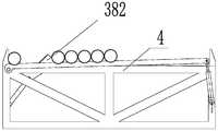
- the pipe storage assemblyfurther includes at least two turning frames and at least two turning driving members; the turning frame is connected to the pipe storage frame, the turning frame has a clamping surface, and the clamping surface includes a first curved surface.
- the folding part and the second bending partmake the clamping surface appear as a concave folding surface, and the turning frame is hinged to the position on the frame body close to the first end of the storage surface; one end of the turning driving part is hinged to the frame body, turning the driving part The other end is hingedly connected with the end of the turning frame away from the clamping surface.
- the pipecan be taken directly from the bottom of the derrick, so there is no need to set up a temporary storage device for pipe tools on the derrick, which reduces the load on the derrick and is beneficial to improve safety;
- the stacking direction of the pipes in the well sitecan be adjusted, which is beneficial to reduce the transportation distance of the pipes from the stacking site to the center of the wellhead, and is beneficial to improve efficiency.
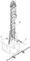
- Fig. 1is a schematic structural diagram of a pipe processing system provided by an embodiment of the present invention when it is connected to a well site and starts to take pipes.
- Fig. 2is a schematic structural diagram of a manipulator provided by an embodiment of the present invention.
- Fig. 3is a schematic structural diagram of a clamping device provided by an embodiment of the present invention.
- Fig. 4is a schematic diagram of the tilting rod of the pipe storage rack provided by the embodiment of the present invention when it is in the first working position.
- Fig. 5is a schematic diagram of a pipe storage assembly provided by an embodiment of the present invention.
- Fig. 6is a schematic diagram when the whipstock bar of the pipe storage assembly provided by the embodiment of the present invention is in a second working position.
- FIG. 7is a schematic diagram of the turning frame of the pipe storage assembly provided by the embodiment of the present invention when one of the pipes is separated.
- Fig. 8is a schematic diagram of the dual-arm robot provided by an embodiment of the present invention when lifting a pipe from the pipe storage assembly.
- Fig. 9is a schematic diagram of the dual-arm robot provided in an embodiment of the present invention in the process of adjusting the posture of the pipe.
- Figure 10is a schematic diagram after the posture adjustment of the pipe is completed.
- Figure 11is a schematic diagram when the pipe is placed above the center of the wellhead after the column is rotated.
- Fig. 12is a schematic structural diagram of a first clamping part provided by an embodiment of the present invention.
- Icon1-derrick; 11-platform; 2-dual-arm robot; 21-upper support frame; 22-post; 23-manipulator; 23a-first manipulator; 23b-second manipulator; 231-block; 232-boom 233-forearm; 234-wrist; 235-clamping device; 2351-first clamping part; 2351a-first transmission rod; 2351b-second transmission rod; 2351c-clamping block; 2351d-clamping power part 2352-Second clamping part; 2353-joint; 2354-clamping frame; 2355-clamping driver; 2356-clamping driving wheel; 236-base; 24-lower support frame; 3-pipe storage assembly 301-pipe storage rack; 31-frame body; 32-stop block; 33-storage space; 34-storage surface; 35-support surface; 36-tilt bar; 37-tilt drive; 38-turning rack 381-First bending part; 382-Second bending part; 39-Turning drive member;
- an embodiment of the present inventionprovides a pipe processing system, which includes a dual-arm robot 2 and a pipe storage assembly 3.
- This pipe tool processing systemcan be used to process pipe tools such as standing roots at the drilling site, move the pipe tool 4 directly from the pipe tool storage site to the wellhead, and adjust the posture of the pipe tool 4 to facilitate the pipe running operation.
- the dual-arm robot 2includes an upper support frame 21, a column 22, a lower support frame 24 and two manipulators 23.
- the upper support frame 21is rotatably connected with the upper end of the column 22, and the upper support frame 21 is used for fixed connection with the derrick 1. Specifically, the upper support frame 21 is provided with a matching hole, and one end of the column 22 is rotatably placed in the matching hole.
- the lower support frame 24is rotatably connected with the lower end of the column 22, and the lower support frame 24 is used for fixed connection with the derrick 1 or the ground. Specifically, the lower support frame 24 is provided with a matching hole, and the other end of the column 22 is rotatably placed in the matching hole.
- the column 22When the column 22 is connected to the upper support frame 21 and the lower support frame 24, the column 22 is arranged along the height direction of the derrick 1, and the column 22 only retains the freedom to rotate around its own axis, so that the column 22 can rotate under the action of external force.
- the two manipulators 23are respectively a first manipulator 23a and a second manipulator 23b.
- the first manipulator 23ais slidably connected to one side of the column 22. Specifically, the first manipulator 23a is slidably connected to the side of the column 22 by a trolley 231.
- the first manipulator 23aincludes a manipulator arm and a clamping device 235. One end of the mechanical arm is connected to the trolley 231, and the other end of the mechanical arm is connected to the clamping device 235.
- the robotic armis configured as a six-degree-of-freedom tandem robotic arm, which includes a base 236, a big arm 232, a small arm 233, and a wrist 234.
- the base 236is fixedly connected to the trolley 231.
- the boom 232is hinged with the base 236, and the rotation axis is perpendicular to the boom 232.
- the forearm 233is hinged with the base 236, and the rotation axis is perpendicular to the forearm 233.
- the wrist 234 and the forearm 233are rotatably connected, so that the wrist 234 can rotate around its own length, and the rotation axis is consistent with the length of the forearm 233.
- the clamping device 235includes a joint 2353, a clamping frame 2354, a first clamping portion 2351, a second clamping portion 2352, a clamping driving member 2355, and a clamping driving wheel 2356.
- One end of the joint 2353is hinged with the wrist 234, and the other end of the joint 2353 is connected with the clamping frame 2354.
- the first clamping portion 2351 and the second clamping portion 2352are both hinged to the clamping frame 2354, and the first clamping portion 2351 and the second clamping portion 2352 are disposed opposite to each other.
- a clamping space that can be opened and closedis formed between the parts 2352.
- the first clamping portion 2351includes a first transmission rod 2351a, a second transmission rod 2351b, a clamping block 2351c, and a clamping power member 2351d.
- One end of the first transmission rod 2351ais hinged with the clamping frame 2354, and the other end is hinged with the clamping block 2351c.
- One end of the second transmission rod 2351bis hinged with the clamping frame 2354, and the other end is hinged with the clamping block 2351c.
- the clamping frame 2354, the first transmission rod 2351a, the second transmission rod 2351b, and the clamping block 2351cform a parallelogram mechanism, so that the clamping block 2351c can always keep moving in translation.
- One end of the clamping power part 2351dis hinged with the clamping frame 2354, and the other end of the clamping power part 2351d is hinged with the first transmission rod 2351a, so that the clamping power part 2351d can drive the first transmission rod 2351a to rotate by extending or shortening.
- One clamping device 235is provided with four clamping driving members 2355 and four clamping driving wheels 2356.
- the clamping driving member 2355 and the clamping driving wheel 2356are connected in one-to-one correspondence, and one clamping driving member 2355 can drive one clamping driving wheel 2356.
- Two of the clamping driving members 2355are disposed on the first clamping portion 2351, and the remaining two clamping driving members 2355 are disposed on the second clamping portion 2352.
- the clamping driving member 2355 and the clamping driving wheel 2356are both installed on the clamping block 2351c.
- the clamping drive wheel 2356is a slewing structure, and in the axial direction of the clamping drive wheel 2356, the cross-sectional area of the middle part is smaller than the cross-sectional area of the two ends. Further, in this embodiment, the side surface of the clamping drive wheel 2356 is a single-blade hyperboloid. Friction lines are also provided on the side surface of the clamping drive wheel 2356.
- the clamping driving member 2355can also be rotated under the action of the clamping driving member 2355, so that the position of the pipe 4 can be adjusted by the friction between the clamping driving wheel 2356 and the pipe 4.
- the clamping driving member 2355is configured as a motor.
- the second manipulator 23bhas the same structure as the first manipulator 23a.
- the second manipulator 23bis connected to the other side of the column 22.
- the second manipulator 23b and the column 22are connected by another trolley 231.
- the second manipulator 23bcan have a sliding speed different from that of the first manipulator 23a with respect to the column 22.
- the pipe storage assembly 3is used to be arranged under the dual-arm robot 2, so that the first manipulator 23a and the second manipulator 23b can be removed from the pipe storage assembly 3 when they are close to the lower end of the column 22 Clamp the pipe 4.
- the pipe storage assembly 3includes a pipe storage rack 301, a tilting driving member 37, a tilting rod 36, a turning frame 38 and a turning driving member 39.
- the pipe storage rack 301includes a rack body 31 and a blocking block 32.
- the frame body 31is a hexahedral frame structure.
- the blocking block 32is connected with the frame body 31.
- the pipe storage assembly 3includes a storage surface 34 and a supporting surface 35 which are arranged oppositely.
- the supporting surface 35is used to contact the ground, the storage surface 34 faces upwards, and the number of stop blocks 32 is four.
- the tops of the four stop blocks 32are higher than the storage surface 34, and the top of the four stop blocks 32 is higher than the storage surface 34.
- a storage space 33is formed in between, and the pipe tool 4 can be placed in the storage space 33.
- the tilting driving member 37is connected to the tilting rod 36, and is used to form slopes in different directions on the storage surface 34, so that the pipe 4 on the storage surface 34 can rotate in a preset direction.
- a tilting driving member 37 and a tilting rod 36are connected to a pipe storage rack 301.
- the whip driving member 37 and the whip rod 36are hingedly connected.
- the tilting driving member 37, the tilting rod 36 and the frame body 31form a triangular structure, wherein the length of one side formed by the tilting driving member 37 can be extended or shortened.
- the skew driving member 37is selected as an oil cylinder.
- the storage surface 34has first and second ends opposed to each other.
- the whipstock bar 36has a first working position and a second working position. When the whip bar 36 is in the first working position, the distance between the first end of the storage surface 34 and the support surface 35 is greater than the distance between the second end of the storage surface 34 and the support surface 35; when the whip bar 36 is in the second working position, the storage The distance from the first end of the surface 34 to the supporting surface 35 is smaller than the distance from the second end of the storage surface 34 to the supporting surface 35.
- the turning drive member 39is fixedly connected to the frame body 31, and the other end of the turning drive member 39 is hinged to the turning frame 38.
- the turning frame 38is hingedly connected to a position on the frame body 31 close to the first end of the storage surface 34.
- the turning driving member 39, the turning frame 38 and the frame body 31form a triangular structure, and one side formed by the turning driving member 39 can be extended or shortened.
- the turnover driving member 39is configured as an oil cylinder.
- the turning frame 38has a clamping surface.
- the clamping surfaceincludes a first bending portion 381 and a second bending portion 382.
- the first bending portion 381is lower than the storage surface 34
- the second bending portion 382is higher than the storage surface 34, so that the second bending portion 382 is formed between the second bending portion 382 and the stop block 32 at one end.
- the space for accommodating a single pipe 4is used to hold the pipe 4 to be picked up or just put down, and the space between the second bending portion 382 and the blocking block 32 at the other end is used for accommodating the remaining pipes 4.
- the turning frame 38rotates, and the pipe tool 4 that has just been put down can roll toward the lower end of the storage surface 34 until the first bending part 381 is higher than the storage surface 34, and the second bending part 381 is higher than the storage surface 34.
- the folded portion 382is lower than the storage surface 34.
- the pipe tool 4can be moved in a preset direction, so that the pipe tool 4 can be easily grasped, put down and stored.
- the upper support frame 21 of the dual-arm robot 2is connected to the derrick 1 and the lower support frame 24 is connected below the working platform 11 of the derrick 1.
- the pipe storage rack 301is placed on the ground and on the side under the dual-arm robot 2, so that the length direction of the pipe 4 on the pipe storage rack 301 is consistent with the direction of the first manipulator 23a pointing to the second manipulator 23b, and the pipe The direction in which the first end of the storage rack 301 points to the second end is perpendicular to the length direction of the pipe 4, and the first end of the storage surface 34 is relatively closer to the dual-arm robot 2;
- the tilting rod 36 of the pipe storage assembly 3is in the second working position, the second bending part 382 of the turning frame 38 is lower than the storage surface 34, and the first bending part 381 is higher than Storage surface 34, a pipe tool 4 will slide along the storage surface 34 to the junction of the first bending portion 381 and the second bending portion 382, and then the turning frame 38 will rotate so that the second bending portion 382 is higher than the storage surface.
- the first bending portion 381is lower than the storage surface 34, and the pipe 4 is separated from the remaining pipes 4 by the second bending portion 382, and is used for clamping by the dual-arm robot 2;
- the first manipulator 23a and the second manipulator 23b of the dual-arm robot 2slide down, the clamping device 235 clamps the pipe 4, and the pipe 4 is matched with the recesses on the side of each clamping drive wheel 2356 .
- the clamping driving member 2355can drive the clamping driving wheel 2356 to rotate, thereby driving the pipe tool 4 to move in the axial direction, thereby adjusting the position of the pipe tool 4.
- the first manipulator 23a and the second manipulator 23bdrive the pipe 4 up.
- the movement speed of the first manipulator 23ais faster than the second manipulator 23b (or the movement speed of the second manipulator 23b is faster than the first manipulator 23a) , So that the posture of the pipe tool 4 is gradually adjusted from horizontal to vertical.
- the pipe tool 4 and the derrick 1are respectively located on both sides of the column 22;
- the column 22rotates to rotate the pipe tool 4 into the derrick 1, and adjust the position so that the pipe tool 4 is aligned with the center of the wellhead, so that the pipe can be lowered.
- the pipe processing system provided by the embodiment of the present inventioncan not only take the pipes directly from the pipe yard, but also can directly lower the pipe 4 lifted from the wellhead to the pipe yard.
- the action process of the lower pipe 4is the same as that of the pipe processing system.
- the aforementioned taking processis the opposite, so I won’t repeat it here.
- Pipescan be taken directly from the position below the platform 11 of the derrick 1, so that there is no need to set up temporary storage devices for pipe tools 4 on the derrick 1, which reduces the load on the derrick 1 and helps reduce the center of gravity of the derrick 1 and is beneficial to improve safety;
- All pipes 4can be stored in the pipe yard, and the pipes 4 can be disassembled in no emergency, reducing unnecessary efficiency waste;
- the placing direction of the pipe tool 4is longitudinal (that is, the derrick 1 is located on the extension line of the pipe tool 4). 4 has a long conveying distance, and through the pipe processing system provided by the embodiment of the present invention, the placement of the pipes 4 in the yard is changed from longitudinal to horizontal, which improves the yard utilization rate and shortens the conveying distance of the pipes 4 ,Improve efficiency.
- the reason why the clamping devices 235 on the first manipulator 23a and the second manipulator 23b are allowed to have different movement speedsis that after the pipe 4 is picked up, the clamping devices on the two manipulators 23 can be passed
- the different movement speed of 235can realize the posture adjustment of the pipe 4.
- thisincludes both the clamping devices 235 on the two manipulators 23 moving at different speeds; it also includes the clamping device 235 on one manipulator 23 moving while the other manipulator
- the situation where the clamping device 235 on 23 remains stationary with respect to the groundthat is, the moving speed is 0);
- the method for generating different movement speeds of the two clamping devices 235 on the two manipulators 23can be obtained through the different sliding speeds of the two manipulators 23 and the posture adjustment of the manipulator 23 itself, as described in this embodiment. , It can also be obtained only by adjusting the posture of the manipulator 23 itself when the length of the manipulator 23 is sufficient;
- the pipe storage assembly 3includes two pipe storage racks 301 arranged at intervals, and each pipe storage rack 301 is provided with a tilting drive member 37, a tilting rod 36, and a turning drive. Piece 39 and a flip frame 38.
- the pipe storage rack 301, the tilting drive member 37, the tilting rod 36, the turning drive member 39, and the turning frame 38need to be provided, the corresponding relationship between the numbers of the above-mentioned five components can also be other. Change, not necessarily in accordance with the form described in this embodiment. That is, a pipe storage rack 301 is not necessarily connected with a tilting rod 36 and a turning rack 38.
- the number of pipe storage racks 301should be set at least one; the number of whip drive members 37 and whip bars 36 should be set at least two, so as to facilitate the formation of the elongated pipe 4 Support, so that the pipe 4 can be placed horizontally; the number of the turning frame 38 and the turning driving member 39 should be at least two, so as to facilitate the accurate separation of the single pipe 4.
- only one pipe storage rack 301may be provided, and at least two tilting drive members 37, at least two tilting rods 36, at least two turning frames 38, and at least two turning drives are connected to this pipe storage rack 301.
- Piece 39is only one pipe storage rack 301, and at least two tilting drive members 37, at least two tilting rods 36, at least two turning frames 38, and at least two turning drives are connected to this pipe storage rack 301.
Landscapes
- Engineering & Computer Science (AREA)
- Life Sciences & Earth Sciences (AREA)
- Geology (AREA)
- Mining & Mineral Resources (AREA)
- Mechanical Engineering (AREA)
- Physics & Mathematics (AREA)
- Environmental & Geological Engineering (AREA)
- Fluid Mechanics (AREA)
- General Life Sciences & Earth Sciences (AREA)
- Geochemistry & Mineralogy (AREA)
- Earth Drilling (AREA)
Abstract
Description
Translated fromChinese本发明涉及一种石油钻采设备机械,特别是一种用于管具处理的双臂机器人及管具处理系统。The invention relates to an oil drilling and production equipment machinery, in particular to a dual-arm robot and a pipe processing system for pipe processing.
在石油天然气钻井系统中,包括陆地钻机和海洋钻机,为了提高其工作效率,特别是为了提高起下钻作业的工作效率,通常会在井架内或外设置钻杆立柱临时储存区域,也就是立根盒区域。钻杆被连接成双根或三根甚至四根行程立根,竖直排放到立根盒区域内。In oil and natural gas drilling systems, including land drilling rigs and offshore drilling rigs, in order to improve their work efficiency, especially to increase the work efficiency of tripping operations, a temporary storage area for drill pipe columns is usually set inside or outside the derrick, that is, standing roots. Box area. The drill rods are connected into double or three or even four-stroke standpipes, and are discharged vertically into the standpipe box area.
为实现上述目的,钻井系统需配置立根盒、排管机、接立根机械手、鼠洞、猫道等诸多设备。这些设备协同作业将通过锚定单根钻杆水平移运到转台,接立根机械手将单根钻杆从水平姿态调整到竖直姿态,并在鼠洞的配合下将单根钻杆连接成立根,并交由排管机排放在立根盒,等井口需要下放立根时,排管机将目标立根从立根盒中取出,并移送至井口,交给顶驱。In order to achieve the above purpose, the drilling system needs to be equipped with a stand-up box, a pipe arranging machine, a stand-up manipulator, a mouse hole, a catwalk and many other equipment. The coordinated operation of these equipments will move a single drill rod horizontally to the turntable by anchoring a single drill rod, and connect the standing manipulator to adjust the single drill rod from a horizontal attitude to a vertical attitude, and connect the single drill rod into a root with the cooperation of the mouse hole. The pipe arranging machine is used to discharge the stand root box. When the wellhead needs to be lowered, the pipe arranging machine removes the target stand root from the stand root box, transfers it to the wellhead, and delivers it to the top drive.
可见立根盒作为立根临时存储装置,是提高工作效率的关键设备之一。立根盒需要有足够大容量来储存所有钻井深度的钻杆,所以立根盒需要有足够的大结构尺寸、结构强度、刚度满足其工作需要。同时,立根盒安装在井架中上部,增加了井架整体的重心高度,且需局部加强来满足连接可靠性。当立根盒内存满立根时,井架的立根载荷将大大增加;满立根情况还大大增加了风载的迎风面积增大了风对井架作用力,同时钻台立根盒区域也需足够结构强度来支撑所有立根的重量。当突发紧急情况时,还需要及时将全部立根从立根盒里取出,拆卸成单根放置在管具堆场。这将造成巨大的工作量,而且造成大量工作效率的浪费。It can be seen that as a temporary storage device for the stand root box, it is one of the key equipment to improve work efficiency. The stand box needs to have a large enough capacity to store drill pipes of all drilling depths, so the stand box needs to have enough large structural size, structural strength, and rigidity to meet its work needs. At the same time, the stand box is installed in the upper part of the derrick, which increases the height of the center of gravity of the derrick as a whole, and needs to be strengthened locally to meet the connection reliability. When the stand root box is full of stand roots, the stand root load of the derrick will be greatly increased; the full stand root situation also greatly increases the windward area of wind load and increases the force of wind on the derrick. At the same time, the stand root box area of the drill floor also needs sufficient structural strength to support it. The weight of all standing roots. When there is an emergency, it is necessary to take out all the stand roots from the stand box in time, disassemble them into single roots and place them in the pipe yard. This will cause a huge workload and waste a lot of work efficiency.
同时立根盒、排管机、接立根机械手、鼠洞、猫道等设备也是钻井系统重 要成本组成之一,这些设备繁多、造价高、重量大,极大地提高了在钻井系统的成本。At the same time, equipment such as standpipe box, pipe arranging machine, standpipe manipulator, mouse hole, catwalk, etc. are also one of the important cost components of the drilling system. The variety of equipment, high cost, and heavy weight greatly increase the cost of the drilling system.
发明内容Summary of the invention
本发明的目的在于:针对现有技术存在的问题,提供一种用于管具处理的双臂机器人及管具处理系统,其能够直接从管具堆场取立根,并调整立根姿态,将立根移运至井口,从而无需再井架上再放置临时立根盒,也不需要采用排管机、接立根机械手、鼠洞、猫道等设备,使得井架载荷大大降低。The purpose of the present invention is to provide a dual-arm robot and a pipe processing system for pipe processing in view of the problems existing in the prior art, which can directly take the standing roots from the pipe yard, and adjust the standing root posture to remove the standing roots. It is moved to the wellhead, so there is no need to place a temporary stand box on the derrick, and no need to use pipe arranging machines, stand-up manipulators, mouse holes, catwalks and other equipment, which greatly reduces the load of the derrick.
为了实现上述目的,本发明采用的技术方案为:In order to achieve the above objectives, the technical solutions adopted by the present invention are as follows:
一方面,本发明提供了一种用于管具处理的双臂机器人,其包括立柱和两个机械手,其中一个机械手与立柱一侧相连,另一个机械手与立柱另一侧相连,机械手包括用于夹持管具的夹持装置,两个机械手上的夹持装置被允许具有不同的运动速度。通过上述的结构,使用时,立柱连接在井架上,双臂机器人的两个机械手从管具堆放现场取管,然后通过夹持装置的不同运动速度调整管具的姿态,便于实现下管。采用上述的用于管具处理的双臂机械人,可以直接从管具堆放现场取管并调节管具的姿态,从而无需在井架上设置管具的临时堆放点,有利于减小井架的载荷,同时能够极大地精简接管设备,进一步减小井架的载荷。On the one hand, the present invention provides a dual-arm robot for pipe processing, which includes a column and two manipulators. One manipulator is connected to one side of the column, and the other manipulator is connected to the other side of the column. The manipulator includes The clamping device for clamping pipes, the clamping devices on the two manipulators are allowed to have different moving speeds. Through the above structure, when in use, the column is connected to the derrick, and the two manipulators of the dual-arm robot take the pipe from the pipe stacking site, and then adjust the posture of the pipe by the different movement speed of the clamping device, which is convenient to realize the pipe down. Using the above-mentioned dual-arm robot for pipe tool processing can directly take pipe from the pipe tool stacking site and adjust the posture of the pipe tool, so that there is no need to set a temporary stacking point for the pipe tool on the derrick, which is beneficial to reduce the load of the derrick. At the same time, it can greatly simplify the takeover equipment and further reduce the load of the derrick.
作为本发明的优选方案,机械手还包括机械臂,机械臂一端用于与立柱可滑动相连,机械臂另一端与夹持装置相连,两个机械手上的机械臂被允许具有不同的滑动速度,机械臂包括六自由度串联机械臂。六自由度串联机械臂的技术成熟、可靠性高,且具备足够多的自由度,能够满足管具姿态变化的需要。As a preferred solution of the present invention, the manipulator also includes a manipulator. One end of the manipulator is used to slidably connect with the column, and the other end of the manipulator is connected with the clamping device. The manipulator arms on the two manipulators are allowed to have different sliding speeds. The arm includes a six-degree-of-freedom tandem mechanical arm. The six-degree-of-freedom tandem manipulator has mature technology, high reliability, and has enough degrees of freedom to meet the needs of pipe posture changes.
作为本发明的优选方案,夹持装置包括接头、夹持架、第一夹持部和第二夹持部;夹持架一端与接头相连,夹持架另一端与第一夹持部和第二夹持部转动相连;第一夹持部和第二夹持部相对设置,第一夹持部与第二夹持部之间形成一个可开合的夹持空间。As a preferred solution of the present invention, the clamping device includes a joint, a clamping frame, a first clamping part and a second clamping part; one end of the clamping frame is connected to the joint, and the other end of the clamping frame is connected to the first clamping part and the second clamping part. The two clamping parts are rotatably connected; the first clamping part and the second clamping part are arranged oppositely, and an openable clamping space is formed between the first clamping part and the second clamping part.
作为本发明的优选方案,第一夹持部包括第一传动杆、第二传动杆、夹持块和夹紧动力件;第一传动杆一端与夹持架铰接,第一传动杆另一端与夹持块铰接;第二传动杆一端与夹持架铰接,第二传动杆另一端与夹持块铰接;夹持架、第一传动杆、第二传动杆和夹持块组成平行四边形机构,夹紧动力件与第一传动杆相连,用于带动第一传动杆转动;第二夹持部与第一夹持部结构相同。通过上述方案,夹持块在运动过程中,能够始终保持平动。As a preferred solution of the present invention, the first clamping part includes a first transmission rod, a second transmission rod, a clamping block and a clamping power part; one end of the first transmission rod is hinged with the clamping frame, and the other end of the first transmission rod is connected with the clamping frame. The clamping block is hinged; one end of the second transmission rod is hinged with the clamping frame, and the other end of the second transmission rod is hinged with the clamping block; the clamping frame, the first transmission rod, the second transmission rod and the clamping block form a parallelogram mechanism, The clamping power part is connected with the first transmission rod for driving the first transmission rod to rotate; the second clamping part has the same structure as the first clamping part. Through the above solution, the clamping block can always keep moving in translation during the movement process.
作为本发明的优选方案,夹紧动力件一端与夹持架铰接,夹紧动力件另一端与第一传动杆铰接;夹紧动力件、第一传动杆与夹持架形成三角形结构,其中夹紧动力件构成的一边可伸长或缩短。As a preferred solution of the present invention, one end of the clamping power part is hinged with the clamping frame, and the other end of the clamping power part is hinged with the first transmission rod; the clamping power part, the first transmission rod and the clamping frame form a triangular structure, wherein the clamping The side formed by the tightening power member can be extended or shortened.
作为本发明的优选方案,夹持装置还包括夹持驱动件和夹持驱动轮,夹持驱动件和夹持驱动轮安装于夹持块上,第一夹持部上设有至少一个夹持驱动件,第二夹持部上也设有至少一个夹持驱动件,夹持驱动件和夹持驱动轮一一对应相连;夹持驱动轮用于与夹持空间中的管具接触。通过设置夹持驱动件和夹持驱动轮,在夹持装置夹起管具时,夹持驱动件能够带动夹持驱动轮转动,从而带动夹持空间中的管具移动,调整管具的位置。As a preferred solution of the present invention, the clamping device further includes a clamping drive member and a clamping drive wheel, the clamping drive member and the clamping drive wheel are mounted on the clamping block, and at least one clamping part is provided on the first clamping part. The second clamping part is also provided with at least one clamping driving member, the clamping driving member and the clamping driving wheel are connected in a one-to-one correspondence; the clamping driving wheel is used for contacting the pipe in the clamping space. By setting the clamping drive and clamping drive wheel, when the clamping device clamps the pipe, the clamping drive can drive the clamping drive wheel to rotate, thereby driving the pipe in the clamping space to move and adjusting the position of the pipe. .
作为本发明的优选方案,在夹持驱动轮的轴向方向上,夹持驱动轮中部的横截面积小于夹持驱动轮两端的横截面积。通过上述的结构,管具能够与夹持驱动轮的凹陷处配合,增加夹持驱动轮与管具的接触面积,使夹持更加稳定。As a preferred solution of the present invention, in the axial direction of the clamping drive wheel, the cross-sectional area of the middle of the clamping drive wheel is smaller than the cross-sectional area of the two ends of the clamping drive wheel. Through the above-mentioned structure, the pipe fitting can be matched with the recess of the clamping drive wheel, which increases the contact area between the clamping drive wheel and the pipe fitting, and makes the clamping more stable.
作为本发明的优选方案,夹持驱动轮的侧面设有摩擦纹。通过这种结构,摩擦纹能够增加夹持驱动轮与管具之间的摩擦力,使得夹持更加稳定;同时在夹持驱动轮转动以调节管具的位置时,也能够避免打滑,便于对管具在夹持空间中的位置实现更精确的调节。As a preferred solution of the present invention, friction lines are provided on the side surface of the clamping drive wheel. Through this structure, the friction pattern can increase the friction between the clamping drive wheel and the pipe tool, making the clamping more stable; at the same time, when the clamping drive wheel rotates to adjust the position of the pipe tool, it can also avoid slippage and facilitate the alignment. The position of the pipe in the clamping space can be adjusted more accurately.
作为本发明的优选方案,机械手与立柱通过滑车相连。As a preferred solution of the present invention, the manipulator and the column are connected by a pulley.
作为本发明的优选方案,双臂机器人还包括上支撑架和下支撑架;上支撑架与立柱一端铰接,下支撑架与立柱另一端铰接。使用时,上支撑架和下支撑 架都可以与井架相连,用于承受双臂机器人在工作过程中受到的弯矩。As a preferred solution of the present invention, the dual-arm robot further includes an upper support frame and a lower support frame; the upper support frame is hinged with one end of the column, and the lower support frame is hinged with the other end of the column. When in use, both the upper support frame and the lower support frame can be connected to the derrick to withstand the bending moment of the dual-arm robot during the working process.
另一方面,本发明还提供了一种管具处理系统,其包括管具存储组件和上述的双臂机器人;管具存储组件用于存放管具,双臂机器人用于从管具存储组件上取管或用于将管具放置在管具存储组件上。使用时,管具存储组件可以直接放置于地面上,管具存储组件以及其上的管件不会对井架造成额外的负载。On the other hand, the present invention also provides a pipe processing system, which includes a pipe storage assembly and the above-mentioned dual-arm robot; the pipe storage assembly is used to store pipes, and the dual-arm robot is used to load the pipe storage assembly from the pipe storage assembly. Take the tube or use it to place the tube on the tube storage assembly. When in use, the pipe storage assembly can be directly placed on the ground, and the pipe storage assembly and the pipe fittings on it will not cause additional load on the derrick.
作为本发明的优选方案,管具存储组件包括管具存储架,所述管具存储架包括架体和至少两个抵挡块;管具存储组件具有存放表面,抵挡块凸设于存放表面并与所述架体相连,至少两个抵挡块之间形成存放空间。As a preferred solution of the present invention, the pipe storage assembly includes a pipe storage rack, the pipe storage rack includes a frame body and at least two resisting blocks; the pipe storage component has a storage surface, and the resisting block is protruding from the storage surface and interacts with The frame bodies are connected, and a storage space is formed between at least two resisting blocks.
作为本发明的优选方案,管具存储组件还包括至少两个造斜驱动件和至少两个造斜杆;造斜杆与管具存储架相连,管具存储架上与存放表面相对的表面为支撑表面;造斜驱动件与造斜杆一一对应相连;造斜杆具有第一工作位置和第二工作位置,造斜杆位于第一工作位置时,存放表面第一端距支撑表面的距离大于存放表面的第二端距支撑表面的距离,造斜杆位于第二工作位置时,存放表面第一端距支撑表面的距离小于存放表面的第二端距支撑表面的距离。通过上述结构,造斜驱动件带动造斜杆的位置在第一工作位置和第二工作位置之间切换,使得管具能够向需要的方向滚动。例如,在需要取管时,使管具向靠近井架的方向滚动;在需要存放管具时,使管具向远离井架的方向滚动。As a preferred solution of the present invention, the pipe storage assembly further includes at least two whipstock driving members and at least two whipstock rods; the whipstock rod is connected to the pipe storage rack, and the surface of the pipe storage rack opposite to the storage surface is Supporting surface; the tilting drive member and the tilting rod are connected in a one-to-one correspondence; the tilting rod has a first working position and a second working position. When the tilting rod is in the first working position, the distance between the first end of the storage surface and the supporting surface The distance between the first end of the storage surface and the supporting surface is smaller than the distance between the second end of the storage surface and the supporting surface when the whipstock bar is in the second working position. Through the above-mentioned structure, the position of the whipstock driving member driven by the whipstock rod is switched between the first working position and the second working position, so that the pipe can be rolled in a required direction. For example, when the pipe needs to be taken, the pipe tool is rolled in the direction close to the derrick; when the pipe tool needs to be stored, the pipe tool is rolled in the direction away from the derrick.
作为本发明的优选方案,造斜杆一端与架体铰接,且造斜杆与架体的连接点靠近于存放表面的第一端;造斜杆另一端靠近于存放表面的第二端,且与造斜驱动件一端铰接,造斜驱动件另一端通过安装耳板与架体铰接;造斜驱动件可伸长或缩短。As a preferred solution of the present invention, one end of the whipstock rod is hinged with the frame body, and the connection point of the whipstock rod and the frame body is close to the first end of the storage surface; the other end of the whipstock rod is close to the second end of the storage surface, and It is hinged with one end of the leaning driving member, and the other end of the leaning driving member is hinged with the frame body through the mounting ear plate; the leaning driving member can be extended or shortened.
作为本发明的优选方案,管具存储组件还包括至少两个翻转架与至少两个翻转驱动件;翻转架与管具存储架相连,翻转架上具有卡持面,卡持面包括第一弯折部和第二弯折部,使卡持面呈现为一个内凹的折面,翻转架与架体上靠近存放表面第一端的位置铰接;翻转驱动件一端与架体铰接,翻转驱动件另一 端与翻转架远离卡持面的一端铰接。通过上述结构,翻转架能够与造斜杆配合,在取杆时,翻转架能够将其中的一根管具与其他管具隔离开来,便于取管操作,避免一次取到多根管的情况。As a preferred solution of the present invention, the pipe storage assembly further includes at least two turning frames and at least two turning driving members; the turning frame is connected to the pipe storage frame, the turning frame has a clamping surface, and the clamping surface includes a first curved surface. The folding part and the second bending part make the clamping surface appear as a concave folding surface, and the turning frame is hinged to the position on the frame body close to the first end of the storage surface; one end of the turning driving part is hinged to the frame body, turning the driving part The other end is hingedly connected with the end of the turning frame away from the clamping surface. Through the above structure, the turning frame can be matched with the tilting rod. When the rod is taken out, the turning frame can isolate one of the pipes from the other pipes, which facilitates the pipe taking operation and avoids the situation of taking multiple pipes at a time. .
综上所述,由于采用了上述技术方案,本发明的有益效果是:In summary, due to the adoption of the above technical solutions, the beneficial effects of the present invention are:
1.可以直接从井架下方取管,从而无需在井架上设置管具临时存放装置,减小了井架承受的载荷,有利于提高安全性;1. The pipe can be taken directly from the bottom of the derrick, so there is no need to set up a temporary storage device for pipe tools on the derrick, which reduces the load on the derrick and is beneficial to improve safety;
2.只需要该管具处理系统即可以实现取管、运输、管具姿态调整和下管等多个功能,从而无需再设置排管机、接立根机械手、鼠洞、猫道等设备,进一步降低了井架载荷,也有利于节省现场布置空间;2. Only the pipe processing system can realize multiple functions such as pipe taking, transportation, pipe posture adjustment and pipe down pipe, so that there is no need to set up pipe arranging machine, connecting standing manipulator, mouse hole, catwalk and other equipment. The load of the derrick is reduced, which is also conducive to saving on-site layout space;
3.通过这种双臂机器人和管具处理系统,管具在井场的堆放方向可以调整,从而有利于减小管具从堆放场地到井口中心处的运输距离,有利于提高效率。3. Through this dual-arm robot and pipe processing system, the stacking direction of the pipes in the well site can be adjusted, which is beneficial to reduce the transportation distance of the pipes from the stacking site to the center of the wellhead, and is beneficial to improve efficiency.
图1是本发明实施例提供的管具处理系统与井场相连并开始取管时的结构示意图。Fig. 1 is a schematic structural diagram of a pipe processing system provided by an embodiment of the present invention when it is connected to a well site and starts to take pipes.
图2是本发明实施例提供的机械手的结构示意图。Fig. 2 is a schematic structural diagram of a manipulator provided by an embodiment of the present invention.
图3是本发明实施例提供的夹持装置的结构示意图。Fig. 3 is a schematic structural diagram of a clamping device provided by an embodiment of the present invention.
图4是本发明实施例提供的管具存储架的造斜杆位于第一工作位置时的示意图。Fig. 4 is a schematic diagram of the tilting rod of the pipe storage rack provided by the embodiment of the present invention when it is in the first working position.
图5是本发明实施例提供的管具存储组件的示意图。Fig. 5 is a schematic diagram of a pipe storage assembly provided by an embodiment of the present invention.
图6是本发明实施例提供的管具存储组件的造斜杆位于第二工作位置时的示意图。Fig. 6 is a schematic diagram when the whipstock bar of the pipe storage assembly provided by the embodiment of the present invention is in a second working position.
图7是本发明实施例提供的管具存储组件的翻转架隔开其中一根管具时的示意图。FIG. 7 is a schematic diagram of the turning frame of the pipe storage assembly provided by the embodiment of the present invention when one of the pipes is separated.
图8是本发明实施例提供的双臂机器人从管具存储组件上提起一根管具时的示意图。Fig. 8 is a schematic diagram of the dual-arm robot provided by an embodiment of the present invention when lifting a pipe from the pipe storage assembly.
图9是本发明实施例提供的双臂机器人进行管具姿态调整过程中的示意图。Fig. 9 is a schematic diagram of the dual-arm robot provided in an embodiment of the present invention in the process of adjusting the posture of the pipe.
图10是管具姿态调整完成后的示意图。Figure 10 is a schematic diagram after the posture adjustment of the pipe is completed.
图11是立柱旋转后,将管具置于井口中心上方时的示意图。Figure 11 is a schematic diagram when the pipe is placed above the center of the wellhead after the column is rotated.
图12是本发明实施例提供的第一夹持部的结构示意图。Fig. 12 is a schematic structural diagram of a first clamping part provided by an embodiment of the present invention.
图标:1-井架;11-平台;2-双臂机器人;21-上支撑架;22-立柱;23-机械手;23a-第一机械手;23b-第二机械手;231-滑车;232-大臂;233-小臂;234-手腕;235-夹持装置;2351-第一夹持部;2351a-第一传动杆;2351b-第二传动杆;2351c-夹持块;2351d-夹紧动力件;2352-第二夹持部;2353-接头;2354-夹持架;2355-夹持驱动件;2356-夹持驱动轮;236-基座;24-下支撑架;3-管具存储组件;301-管具存储架;31-架体;32-抵挡块;33-存放空间;34-存放表面;35-支撑表面;36-造斜杆;37-造斜驱动件;38-翻转架;381-第一弯折部;382-第二弯折部;39-翻转驱动件;4-管具。Icon: 1-derrick; 11-platform; 2-dual-arm robot; 21-upper support frame; 22-post; 23-manipulator; 23a-first manipulator; 23b-second manipulator; 231-block; 232-boom 233-forearm; 234-wrist; 235-clamping device; 2351-first clamping part; 2351a-first transmission rod; 2351b-second transmission rod; 2351c-clamping block; 2351d-clamping power part 2352-Second clamping part; 2353-joint; 2354-clamping frame; 2355-clamping driver; 2356-clamping driving wheel; 236-base; 24-lower support frame; 3-pipe storage assembly 301-pipe storage rack; 31-frame body; 32-stop block; 33-storage space; 34-storage surface; 35-support surface; 36-tilt bar; 37-tilt drive; 38-turning rack 381-First bending part; 382-Second bending part; 39-Turning drive member; 4-Pipe tool.
下面结合附图,对本发明作详细的说明。The present invention will be described in detail below in conjunction with the accompanying drawings.
为了使本发明的目的、技术方案及优点更加清楚明白,以下结合附图及实施例,对本发明进行进一步详细说明。应当理解,此处所描述的具体实施例仅用以解释本发明,并不用于限定本发明。In order to make the objectives, technical solutions, and advantages of the present invention clearer, the following further describes the present invention in detail with reference to the accompanying drawings and embodiments. It should be understood that the specific embodiments described here are only used to explain the present invention, but not used to limit the present invention.
实施例Example
请参阅图1,本发明实施例提供了一种管具处理系统,其包括双臂机器人2及管具存储组件3。这种管具处理系统能够用于在钻井现场处理立根等管具,将管具4直接从管具存储场地移动到井口,并调整管具4的姿态,便于进行下管操作。具体的:Please refer to FIG. 1, an embodiment of the present invention provides a pipe processing system, which includes a dual-
双臂机器人2包括上支撑架21、立柱22、下支撑架24和两个机械手23。The dual-
上支撑架21与立柱22上端可转动地相连,上支撑架21用于与井架1固定相连。具体的,上支撑架21上设有配合孔,立柱22一端可转动地置于配合孔中。The
下支撑架24与立柱22下端可转动地相连,下支撑架24用于与井架1或地面固定相连。具体的,下支撑架24上设有配合孔,立柱22另一端可转动地置于配合孔中。The
当立柱22与上支撑架21和下支撑架24相连时,立柱22沿井架1的高度方向设置,立柱22只保留绕自身轴线自转的自由度,使得立柱22能够在外力的作用下自转。When the
两个机械手23分别为第一机械手23a和第二机械手23b。The two
第一机械手23a与立柱22一侧可滑动地相连。具体的,第一机械手23a与立柱22一侧通过滑车231可滑动地相连。The
第一机械手23a包括机械臂和夹持装置235。机械臂一端与滑车231相连,机械臂另一端与夹持装置235相连。The
请参阅图2,在本实施例中,机械臂被设置为六自由度串联机械臂,其包括基座236、大臂232、小臂233和手腕234。基座236与滑车231固定相连。大臂232与基座236铰接,转动轴线垂直于大臂232。小臂233与基座236铰接,转动轴线垂直于小臂233。手腕234与小臂233可转动相连,使得手腕234可以绕自身长度方向转动,且转动轴线与小臂233的长度方向一致。Referring to FIG. 2, in this embodiment, the robotic arm is configured as a six-degree-of-freedom tandem robotic arm, which includes a
请参阅图3,夹持装置235包括接头2353、夹持架2354、第一夹持部2351、第二夹持部2352、夹持驱动件2355和夹持驱动轮2356。Please refer to FIG. 3, the
接头2353一端与手腕234铰接,接头2353另一端与夹持架2354相连。第一夹持部2351和第二夹持部2352均与夹持架2354铰接,且第一夹持部2351 与第二夹持部2352相对设置,在第一夹持部2351与第二夹持部2352之间形成一个可开合的夹持空间。One end of the joint 2353 is hinged with the
请参阅图12,第一夹持部2351包括第一传动杆2351a、第二传动杆2351b、夹持块2351c和夹紧动力件2351d。第一传动杆2351a一端与夹持架2354铰接,另一端与夹持块2351c铰接。第二传动杆2351b一端与夹持架2354铰接,另一端与夹持块2351c铰接。夹持架2354、第一传动杆2351a、第二传动杆2351b与夹持块2351c组成平行四边形机构,使得夹持块2351c在工作时能够始终保持平动。Referring to FIG. 12, the
夹紧动力件2351d一端与夹持架2354铰接,夹紧动力件2351d另一端与第一传动杆2351a铰接,使得夹紧动力件2351d能够通过伸长或缩短带动第一传动杆2351a转动。One end of the clamping
一个夹持装置235上设有四个夹持驱动件2355和四个夹持驱动轮2356。夹持驱动件2355和夹持驱动轮2356一一对应相连,一个夹持驱动件2355可驱动一个夹持驱动轮2356。其中两个夹持驱动件2355设置于第一夹持部2351上,其余两个夹持驱动件2355设置于第二夹持部2352上。具体的,夹持驱动件2355和夹持驱动轮2356均安装于夹持块2351c上。One
夹持驱动轮2356为回转体结构,且在夹持驱动轮2356的轴向方向上,其中部的横截面积小于两端的横截面积。进一步的,在本实施例中,夹持驱动轮2356的侧面为单叶双曲面。夹持驱动轮2356的侧面还设有摩擦纹。当第一夹持部2351和第二夹持部2352用于夹持管具4时,夹持空间中的管具4与夹持驱动轮2356相接触,通过夹持驱动轮2356中部的凹陷部分可以增加夹持驱动轮2356与管具4之间的接触面积,实现更加稳定的夹持。夹持驱动件2355还可以在夹持驱动件2355的作用下转动,从而通过夹持驱动轮2356与管具4之间的摩擦力调节管具4的位置。具体的,本实施例中,夹持驱动件2355被设置为电机。The clamping
第二机械手23b与第一机械手23a的结构相同。第二机械手23b与立柱22另一侧相连。第二机械手23b与立柱22通过另一个滑车231相连。第二机械手23b能够相对于立柱22具有与第一机械手23a不同的滑动速度。The
请参阅图4-图7,管具存储组件3用于设置于双臂机器人2的下方,使得第一机械手23a和第二机械手23b在靠近于立柱22下端时,能够从管具存储组件3上夹取管具4。4-7, the
管具存储组件3包括管具存储架301、造斜驱动件37、造斜杆36、翻转架38和翻转驱动件39。The
其中,管具存储架301包括架体31和抵挡块32。在本实施例中,架体31为六面体框架结构。抵挡块32与架体31相连。The
管具存储组件3上包括相对设置的存放表面34和支撑表面35。在存放管具4时,支撑表面35用于与地面接触,存放表面34朝上,抵挡块32的数量为四个,四个抵挡块32的顶部高于存放表面34,在四个抵挡块32之间形成一个存放空间33,管具4可以放置于存放空间33中。The
造斜驱动件37与造斜杆36相连,用于在存放表面34上形成不同方向的斜度,使存放表面34上的管具4能够向预设的方向转动。具体的,一个管具存储架301上连接有一个造斜驱动件37和一个造斜杆36。造斜驱动件37和造斜杆36铰接相连。The
造斜驱动件37一端通过安装耳板与架体31的侧面铰接相连,造斜驱动件37另一端与造斜杆36一端铰接,造斜杆36另一端与架体31铰接。造斜驱动件37、造斜杆36与架体31组成三角形结构,其中造斜驱动件37所构成的一边的长度可伸张或缩短。具体的,本实施例中,造斜驱动件37选择为油缸。One end of the
存放表面34具有相对设置的第一端和第二端。造斜杆36具有第一工作位置和第二工作位置。造斜杆36位于第一工作位置时,存放表面34第一端距支撑表面35的距离大于存放表面34的第二端距支撑表面35的距离;造斜杆36 位于第二工作位置时,存放表面34第一端距支撑表面35的距离小于存放表面34的第二端距支撑表面35的距离。The
翻转驱动件39一端与架体31固定相连,翻转驱动件39另一端与翻转架38铰接。翻转架38与架体31上靠近存放表面34的第一端的位置铰接。翻转驱动件39、翻转架38与架体31形成一个三角结构,且由翻转驱动件39构成的一边可伸长或缩短。具体的,翻转驱动件39被设置为油缸。One end of the turning
翻转架38上具有卡持面,具体的,卡持面包括第一弯折部381和第二弯折部382。在翻转驱动件39缩短时,第一弯折部381低于存放表面34,第二弯折部382高于存放表面34,使得第二弯折部382与一端的抵挡块32之间形成用于容纳单根管具4的空间,从而夹持住待抓起或刚被放下的管具4,第二弯折部382与另一端的抵挡块32之间则用于容纳其余的管具4。在翻转驱动件39伸长时,翻转架38旋转,则刚被放下的管具4可以向存放表面34上的较低端滚动,直到第一弯折部381高于存放表面34,第二弯折部382低于存放表面34。The turning
通过翻转驱动件39、翻转架38、造斜驱动件37、造斜杆36的配合,可以实现管具4向预设的方向运动,从而便于抓取、放下和存储管具4。Through the cooperation of the turning
本发明提供的管具处理系统的工作原理在于:The working principle of the pipe processing system provided by the present invention is as follows:
使用时,将双臂机器人2的上支撑架21连接在井架1上,下支撑架24连接在井架1的工作平台11以下。管具存储架301放置于地面,且位于双臂机器人2下方的侧面,使管具存储架301上的管具4的长度方向与第一机械手23a指向第二机械手23b的方向一致,且管具存储架301的第一端指向第二端的方向与管具4的长度方向垂直,存放表面34的第一端相对更靠近于双臂机器人2;In use, the
在需要提起一根立柱22时,使管具存储组件3的造斜杆36位于第二工作位置,翻转架38的第二弯折部382低于存放表面34,第一弯折部381高于存放表面34,则一根管具4将沿存放表面34滑动至第一弯折部381和第二弯折部382的连接处,然后翻转架38转动,使第二弯折部382高于存放表面34,第一 弯折部381低于存放表面34,该管具4与其余管具4被第二弯折部382隔离开,用于供双臂机器人2夹持;When a
请参阅图8-图10,双臂机器人2的第一机械手23a和第二机械手23b下滑,夹持装置235夹住该管具4,管具4与各个夹持驱动轮2356侧面的凹陷处配合。此时,夹持驱动件2355可带动夹持驱动轮2356转动,从而带动管具4沿轴线方向移动,从而调节管具4的位置。然后第一机械手23a和第二机械手23b带动管具4上行,在这个过程中,第一机械手23a的运动速度快于第二机械手23b(或第二机械手23b的运动速度快于第一机械手23a),使得管具4的姿态从水平向被逐渐调整到竖直向,此时管具4与井架1分别位于立柱22的两侧;Please refer to Figures 8-10, the
请参阅图11,最后立柱22转动,将管具4旋转到井架1中,并调整位置使得管具4对准井口中心,从而可以实现下管。Referring to Fig. 11, finally the
本发明实施例提供的管具处理系统除了可直接从管具堆场取管外,还可以将从井口中提起的管具4直接下放到管具堆场,下放管具4的作动过程与前述取管过程相反,再此不予赘述。The pipe processing system provided by the embodiment of the present invention can not only take the pipes directly from the pipe yard, but also can directly lower the
本发明实施例提供的管具处理系统的有益效果在于:The beneficial effects of the pipe treatment system provided by the embodiment of the present invention are:
1.可以直接从井架1的平台11以下的位置取管,从而无需在井架1上设置管具4临时存放装置,减小了井架1承受的载荷,有利于降低井架1的重心,有利于提高安全性;1. Pipes can be taken directly from the position below the
2.只需要该管具处理系统即可以实现取管、运输、管具4姿态调整和下管等多个功能,从而无需再重复设置排管机、接立根机械手、鼠洞、猫道等设备,进一步降低了井架1载荷,也有利于节省现场布置空间;2. Only the pipe processing system can realize multiple functions such as pipe taking, transportation,
3.所有管具4都可存储于管具堆场,无紧急情况下管具4拆卸作业,减少不必要的效率浪费;3. All
4.现有技术中,为了便于管具4的搬运和提升,管具4的摆放方向都为纵 向(即井架1位于管具4的延长线上),这种摆放方式下,管具4的搬运距离较长,而通过本发明实施例提供的上述管具处理系统,管具4在堆场的摆放姿态从纵向改为横向,提供了堆场利用率,缩短管具4搬运距离,提高效率。4. In the prior art, in order to facilitate the handling and lifting of the
需要说明的是:It should be noted:
在本申请中,第一机械手23a和第二机械手23b上的夹持装置235被允许具有不同的运动速度的原因是:在抓起管具4后,可以通过两个机械手23上的夹持装置235的不同运动速度,实现管具4的姿态调整。本领域技术人员可以预见,这既包括两个机械手23上的夹持装置235均产生运动、且运动速度不同的情况;也包括其中一个机械手23上的夹持装置235产生运动,而另一个机械手23上的夹持装置235保持相对地面的静止(即运动速度为0)的情况;In this application, the reason why the clamping
另外,关于两个机械手23上的两个夹持装置235的不同运动速度的产生方法,既可以如本实施例所述,通过两个机械手23的不同滑动速度和机械手23本身的姿态调整而得到,也可以在机械手23的长度足够的情况下,仅仅通过机械手23本身的姿态调整而得到;In addition, the method for generating different movement speeds of the two
在本实施例中,管具存储组件3包括间隔设置的两个管具存储架301,每一个管具存储架301上均设有一个造斜驱动件37、一个造斜杆36、一个翻转驱动件39和一个翻转架38。在本发明的其他实施方式中,若需要设置管具存储架301、造斜驱动件37、造斜杆36、翻转驱动件39和翻转架38,上述五个部件的数量对应关系还可以有其他变化,而不必然依照本实施例所述的形式。即:一个管具存储架301上并不必然连接一个造斜杆36和一个翻转架38。在整个管具存储组件3中:管具存储架301的数量应设置至少一个;造斜驱动件37和造斜杆36的数量应设置至少两个,从而便于对细长型的管具4形成支撑,使管具4能够被水平地放置;翻转架38与翻转驱动件39的数量应设置至少两个,从而便于准确地分隔单根管具4。例如,可以只设置一个管具存储架301,这个管具存储架301上连接有至少两个造斜驱动件37、至少两个造斜杆36、至少两个翻 转架38、至少两个翻转驱动件39。In this embodiment, the
以上所述仅为本发明的较佳实施例而已,并不用以限制本发明,凡在本发明的精神和原则之内所作的任何修改、等同替换和改进等,均应包含在本发明的保护范围之内。The above descriptions are only preferred embodiments of the present invention and are not intended to limit the present invention. Any modification, equivalent replacement and improvement made within the spirit and principle of the present invention shall be included in the protection of the present invention. Within range.
Claims (15)
Translated fromChineseApplications Claiming Priority (2)
| Application Number | Priority Date | Filing Date | Title |
|---|---|---|---|
| CN201911215108.1 | 2019-12-02 | ||
| CN201911215108.1ACN112983304B (en) | 2019-12-02 | 2019-12-02 | Double-arm robot for pipe treatment and pipe treatment system |
Publications (1)
| Publication Number | Publication Date |
|---|---|
| WO2021109532A1true WO2021109532A1 (en) | 2021-06-10 |
Family
ID=76222450
Family Applications (1)
| Application Number | Title | Priority Date | Filing Date |
|---|---|---|---|
| PCT/CN2020/095931CeasedWO2021109532A1 (en) | 2019-12-02 | 2020-06-12 | Dual-arm robot for pipe processing, and pipe processing system |
Country Status (2)
| Country | Link |
|---|---|
| CN (1) | CN112983304B (en) |
| WO (1) | WO2021109532A1 (en) |
Cited By (7)
| Publication number | Priority date | Publication date | Assignee | Title |
|---|---|---|---|---|
| CN116241198A (en)* | 2023-03-20 | 2023-06-09 | 北京化工大学 | A drill pipe auxiliary handling manipulator |
| CN116517483A (en)* | 2023-01-13 | 2023-08-01 | 中石化石油工程技术服务有限公司 | Double-deck bench manipulator above monkey bench |
| WO2024184396A1 (en)* | 2023-03-06 | 2024-09-12 | Ter Bron Groep B.V. | Hydraulic workover unit with tubular handling mechanism for positioning tubulars above a well head |
| WO2025006349A1 (en)* | 2023-06-27 | 2025-01-02 | National Oilwell Varco, L.P. | Robotic system for horizontal pipe handling on a drill rig |
| CN119321286A (en)* | 2024-09-24 | 2025-01-17 | 东海实验室 | Pipe tool warehouse device for submarine drilling machine |
| CN119878031A (en)* | 2025-03-31 | 2025-04-25 | 天津市华灵科技有限公司 | Drill floor, mounting method of drill floor stand box and pipe arranging method |
| US12345105B2 (en) | 2020-07-15 | 2025-07-01 | National Oilwell Varco, L.P. | Horizontal racking and stand building system |
Families Citing this family (2)
| Publication number | Priority date | Publication date | Assignee | Title |
|---|---|---|---|---|
| CN114523472B (en)* | 2022-01-24 | 2023-05-23 | 湖南视比特机器人有限公司 | Workpiece collaborative grabbing method, system and storage medium |
| CN119711964B (en)* | 2025-02-27 | 2025-04-29 | 塞纳博科石油技术服务有限公司 | Automatic change area and press workover rig |
Citations (6)
| Publication number | Priority date | Publication date | Assignee | Title |
|---|---|---|---|---|
| CN203188943U (en)* | 2012-09-16 | 2013-09-11 | 中国石油集团长城钻探工程有限公司工程服务公司 | Drilling machine iron stand device |
| CN104389536A (en)* | 2014-11-20 | 2015-03-04 | 四川宏华石油设备有限公司 | Pipe tool transportation mechanical arm |
| CN106639921A (en)* | 2016-07-27 | 2017-05-10 | 胜利油田胜利动力机械集团有限公司石油机械分公司 | Automatic tube and rod conveyor |
| US20180087322A1 (en)* | 2015-04-17 | 2018-03-29 | Suk Shin In | Rod mounting device for boring machine |
| CN111005691A (en)* | 2019-12-02 | 2020-04-14 | 四川宏华石油设备有限公司 | Drilling machine |
| CN111119736A (en)* | 2019-12-02 | 2020-05-08 | 四川宏华石油设备有限公司 | Drilling machine |
Family Cites Families (10)
| Publication number | Priority date | Publication date | Assignee | Title |
|---|---|---|---|---|
| DE3301536A1 (en)* | 1983-01-19 | 1984-07-19 | Kraftwerk Union AG, 4330 Mülheim | TUBE GATE MANIPULATOR |
| JP2545738B2 (en)* | 1994-02-28 | 1996-10-23 | 工業技術院長 | Robot hand for forging work |
| US9115550B2 (en)* | 2012-04-14 | 2015-08-25 | Kasia L. Robnett | Robotic disassembly method at a well site |
| CN103659715B (en)* | 2013-12-10 | 2018-07-10 | 山东科技大学 | Hoseline connects manipulator |
| CN204827278U (en)* | 2015-06-24 | 2015-12-02 | 青岛杰瑞工控技术有限公司 | Oil -well rig quadruple board platform tubular column discharges manipulator |
| CN105401896B (en)* | 2015-11-02 | 2017-12-08 | 湖南三一石油科技有限公司 | Oil drilling and extracting equipment, drilling floor surface manipulator and pulley mechanism |
| CN205349253U (en)* | 2016-01-22 | 2016-06-29 | 中石化石油工程机械有限公司第四机械厂 | Automatic discharging equipment of drilling string |
| CN207076735U (en)* | 2017-08-21 | 2018-03-09 | 上海宗豪智能科技有限公司 | Pipeline cleaning robot deviation rectification mechanism |
| CN108145335B (en)* | 2018-01-20 | 2020-07-31 | 安徽绩溪徽山链传动有限公司 | Rectangular pipe grabbing and conveying system with self-adaptive length |
| CN211598565U (en)* | 2019-12-02 | 2020-09-29 | 四川宏华石油设备有限公司 | Double-arm robot for pipe treatment and pipe treatment system |
- 2019
- 2019-12-02CNCN201911215108.1Apatent/CN112983304B/enactiveActive
- 2020
- 2020-06-12WOPCT/CN2020/095931patent/WO2021109532A1/ennot_activeCeased
Patent Citations (6)
| Publication number | Priority date | Publication date | Assignee | Title |
|---|---|---|---|---|
| CN203188943U (en)* | 2012-09-16 | 2013-09-11 | 中国石油集团长城钻探工程有限公司工程服务公司 | Drilling machine iron stand device |
| CN104389536A (en)* | 2014-11-20 | 2015-03-04 | 四川宏华石油设备有限公司 | Pipe tool transportation mechanical arm |
| US20180087322A1 (en)* | 2015-04-17 | 2018-03-29 | Suk Shin In | Rod mounting device for boring machine |
| CN106639921A (en)* | 2016-07-27 | 2017-05-10 | 胜利油田胜利动力机械集团有限公司石油机械分公司 | Automatic tube and rod conveyor |
| CN111005691A (en)* | 2019-12-02 | 2020-04-14 | 四川宏华石油设备有限公司 | Drilling machine |
| CN111119736A (en)* | 2019-12-02 | 2020-05-08 | 四川宏华石油设备有限公司 | Drilling machine |
Cited By (8)
| Publication number | Priority date | Publication date | Assignee | Title |
|---|---|---|---|---|
| US12345105B2 (en) | 2020-07-15 | 2025-07-01 | National Oilwell Varco, L.P. | Horizontal racking and stand building system |
| CN116517483A (en)* | 2023-01-13 | 2023-08-01 | 中石化石油工程技术服务有限公司 | Double-deck bench manipulator above monkey bench |
| WO2024184396A1 (en)* | 2023-03-06 | 2024-09-12 | Ter Bron Groep B.V. | Hydraulic workover unit with tubular handling mechanism for positioning tubulars above a well head |
| NL2034271B1 (en)* | 2023-03-06 | 2024-09-18 | Ter Bron Groep B V | Hydraulic workover unit with tubular handling mechanism for positioning tubulars above a well head. |
| CN116241198A (en)* | 2023-03-20 | 2023-06-09 | 北京化工大学 | A drill pipe auxiliary handling manipulator |
| WO2025006349A1 (en)* | 2023-06-27 | 2025-01-02 | National Oilwell Varco, L.P. | Robotic system for horizontal pipe handling on a drill rig |
| CN119321286A (en)* | 2024-09-24 | 2025-01-17 | 东海实验室 | Pipe tool warehouse device for submarine drilling machine |
| CN119878031A (en)* | 2025-03-31 | 2025-04-25 | 天津市华灵科技有限公司 | Drill floor, mounting method of drill floor stand box and pipe arranging method |
Also Published As
| Publication number | Publication date |
|---|---|
| CN112983304B (en) | 2024-04-09 |
| CN112983304A (en) | 2021-06-18 |
Similar Documents
| Publication | Publication Date | Title |
|---|---|---|
| WO2021109532A1 (en) | Dual-arm robot for pipe processing, and pipe processing system | |
| US8936424B1 (en) | Vertical pipe handler with pivoting arms and smart grip | |
| EP1799955B1 (en) | Tubular handling apparatus and a drilling rig | |
| CN206608120U (en) | Land rig connects the tubing string processing system of thribble offline | |
| US3561811A (en) | Well pipe racker | |
| CN111706255B (en) | A double-rotation automatic drilling rig host | |
| WO2017133561A1 (en) | Automated drilling rig | |
| CN107521632B (en) | Wellbore Drilling System, Offshore Drilling Vessel, Drilling Method and Exchange Method | |
| CN111119736B (en) | Drilling machine | |
| CN111005691B (en) | Drilling machine | |
| CN201419983Y (en) | Drilling platform knuckle boom crane | |
| CN112343525B (en) | Compact type efficient operation drilling machine and method | |
| WO2017166915A1 (en) | Pipe processing device | |
| CN205532274U (en) | Automatic change rig | |
| WO2022033397A1 (en) | Multifunctional manipulator | |
| CN112343524B (en) | Efficient operation drilling machine and method | |
| CN204238881U (en) | A kind of pipe movement manipulator | |
| CN106194067A (en) | Off-line sets up root device | |
| CN109138897A (en) | Well head centralising device and with its well workover equip | |
| CN209277844U (en) | Well head centralising device and with its well workover equip | |
| WO2018152968A1 (en) | Drilling tool automatic transfer apparatus of drill used for continental scientific drilling | |
| WO2022062749A1 (en) | Compact efficient operation drilling rig and method | |
| JPH0544385A (en) | Horizontal pipe connection / separation device | |
| CN211598564U (en) | Pipe handling robot and handling system | |
| CN211598565U (en) | Double-arm robot for pipe treatment and pipe treatment system |
Legal Events
| Date | Code | Title | Description |
|---|---|---|---|
| 121 | Ep: the epo has been informed by wipo that ep was designated in this application | Ref document number:20897400 Country of ref document:EP Kind code of ref document:A1 | |
| NENP | Non-entry into the national phase | Ref country code:DE | |
| 122 | Ep: pct application non-entry in european phase | Ref document number:20897400 Country of ref document:EP Kind code of ref document:A1 |