WO2021107039A1 - Robot hand - Google Patents
Robot handDownload PDFInfo
- Publication number
- WO2021107039A1 WO2021107039A1PCT/JP2020/044078JP2020044078WWO2021107039A1WO 2021107039 A1WO2021107039 A1WO 2021107039A1JP 2020044078 WJP2020044078 WJP 2020044078WWO 2021107039 A1WO2021107039 A1WO 2021107039A1
- Authority
- WO
- WIPO (PCT)
- Prior art keywords
- swing
- robot hand
- claw
- rotating shaft
- members
- Prior art date
- Legal status (The legal status is an assumption and is not a legal conclusion. Google has not performed a legal analysis and makes no representation as to the accuracy of the status listed.)
- Ceased
Links
Images


Classifications
- B—PERFORMING OPERATIONS; TRANSPORTING
- B25—HAND TOOLS; PORTABLE POWER-DRIVEN TOOLS; MANIPULATORS
- B25J—MANIPULATORS; CHAMBERS PROVIDED WITH MANIPULATION DEVICES
- B25J15/00—Gripping heads and other end effectors
- B25J15/04—Gripping heads and other end effectors with provision for the remote detachment or exchange of the head or parts thereof
- B25J15/0475—Exchangeable fingers
- B—PERFORMING OPERATIONS; TRANSPORTING
- B25—HAND TOOLS; PORTABLE POWER-DRIVEN TOOLS; MANIPULATORS
- B25J—MANIPULATORS; CHAMBERS PROVIDED WITH MANIPULATION DEVICES
- B25J15/00—Gripping heads and other end effectors
- B25J15/02—Gripping heads and other end effectors servo-actuated
- B25J15/0206—Gripping heads and other end effectors servo-actuated comprising articulated grippers
- B25J15/0226—Gripping heads and other end effectors servo-actuated comprising articulated grippers actuated by cams
- B—PERFORMING OPERATIONS; TRANSPORTING
- B25—HAND TOOLS; PORTABLE POWER-DRIVEN TOOLS; MANIPULATORS
- B25J—MANIPULATORS; CHAMBERS PROVIDED WITH MANIPULATION DEVICES
- B25J15/00—Gripping heads and other end effectors
- B25J15/04—Gripping heads and other end effectors with provision for the remote detachment or exchange of the head or parts thereof
- B25J15/0408—Connections means
- B25J15/0425—Connections means having cams
- B—PERFORMING OPERATIONS; TRANSPORTING
- B25—HAND TOOLS; PORTABLE POWER-DRIVEN TOOLS; MANIPULATORS
- B25J—MANIPULATORS; CHAMBERS PROVIDED WITH MANIPULATION DEVICES
- B25J15/00—Gripping heads and other end effectors
- B25J15/08—Gripping heads and other end effectors having finger members
- B—PERFORMING OPERATIONS; TRANSPORTING
- B25—HAND TOOLS; PORTABLE POWER-DRIVEN TOOLS; MANIPULATORS
- B25J—MANIPULATORS; CHAMBERS PROVIDED WITH MANIPULATION DEVICES
- B25J15/00—Gripping heads and other end effectors
- B25J15/08—Gripping heads and other end effectors having finger members
- B25J15/10—Gripping heads and other end effectors having finger members with three or more finger members
- B25J15/106—Gripping heads and other end effectors having finger members with three or more finger members moving in parallel relationship
Definitions
- FIG. 6is a partial perspective view for showing an example of the shim, and mainly shows the support members 20a and 20b, the swing member 50, the claw member 30a, the screw T, and the shim 21, and the other parts are omitted. ing. Further, the support members 20a and 20b are expressed transparently. In the drawings prior to FIG. 6, one screw T was provided for each of the support members 20a and 20b for the sake of simplification of the description, but in FIG. 6, two screws T are provided for each.
- the support members 20a and 20bare fixed to the bracket 10 (not shown in FIG. 6) by screws T, but in FIG. 6, the side in contact with the bracket 10 is facing up.
- the shim 21is a thin metal plate, and has two holes for passing the screw T.
- the cover 60is formed with an opening 61, which is intended to be multifunctional through a through hole 43 when the rotating shaft 40 is made into a hollow shaft shape, and is inside the robot hand 1. It has a structure that does not leak pollutants. Further, since the structure does not leak the polluted substances inside the robot hand 1, it also has a function of reducing the invasion of dust from the outside of the robot hand 1. The durability of the robot hand 1 can be improved by preventing foreign matter from entering the meshing portion between the worm gear portion 41 and the worm wheel portion 51.
- the regulation groove 55is formed on the swinging member 50 side, and the regulation pin P5 is fixed to the non-swinging support member 20b, but the present invention is not limited to this.
- the regulation pin P5is fixed at a position radially away from the center hole 53 on the side surface 52a of the rocking member 50, and the regulation pin P5 can move inside on the surface of the support member 20b facing the side surface 52a. Therefore, a regulation groove may be provided to regulate the movement range of the regulation pin P5. In this way, it is possible to reverse the relationship between the regulation pin P5 and the regulation groove as long as the replacement of the swing member 50 and the assembly of the robot hand 1 are not hindered.
Landscapes
- Engineering & Computer Science (AREA)
- Robotics (AREA)
- Mechanical Engineering (AREA)
- Manipulator (AREA)
Abstract
Description
Translated fromJapanese本発明は、ロボットハンドに関する。The present invention relates to a robot hand.
特許文献1には、ロボットハンドが記載されている。このようなロボットハンドは、モータの動力を受けたギヤ同士が噛み合うことにより爪部材が駆動する。Patent Document 1 describes a robot hand. In such a robot hand, the claw member is driven by the meshing of the gears powered by the motor.
上記特許文献1では、爪部は、歯車に対してロボットハンドの軸心方向の前方側に固定されている。このため、爪部により把持可能な対象物には制限がある。また、歯車の周辺はカバーにより覆われているため、ロボットハンドが大型化している。更に、爪部と歯車とが固定された部位の周辺もカバーにより覆われているため、爪部の交換の際には、まずこのようなカバーを取り外す必要があり、交換作業が煩雑化している。In Patent Document 1, the claw portion is fixed to the gear on the front side in the axial direction of the robot hand. Therefore, there is a limit to the object that can be gripped by the claw portion. Moreover, since the periphery of the gear is covered with a cover, the size of the robot hand is increased. Furthermore, since the area around the portion where the claw and the gear are fixed is also covered with a cover, it is necessary to first remove such a cover when replacing the claw, which complicates the replacement work. ..
そこで本発明は、把持可能な対象物の範囲が拡大しており、小型化され、更に爪部の交換作業も容易なロボットハンドを提供することを目的とする。Therefore, an object of the present invention is to provide a robot hand in which the range of objects that can be gripped is expanded, the size is reduced, and the claw portion can be easily replaced.
上記目的は、回転軸を有したモータと、前記回転軸の先端部を収容した収容部材と、前記回転軸が回転することにより前記収容部材に対して揺動する複数の揺動部材と、複数の前記揺動部材のそれぞれと共に揺動する複数の爪部材と、を備え、前記回転軸は、外周にウォームギヤ部が形成されており、前記揺動部材は、外周の一部に前記ウォームギヤ部に噛み合うウォームホイール部と、外周の一部に当該揺動部材の揺動中心を介して前記回転軸とは反対側に設けられた固定面と、を含み、前記爪部材は、第1固定部材により取り外し可能に前記固定面に固定され、前記収容部材は、前記第1固定部材を取り外し可能に露出している、ロボットハンドによって達成できる。The object is a motor having a rotating shaft, an accommodating member accommodating the tip end portion of the rotating shaft, and a plurality of swinging members that swing with respect to the accommodating member due to the rotation of the rotating shaft. A plurality of claw members that swing together with each of the swing members of the above are provided, and a worm gear portion is formed on the outer periphery of the rotating shaft, and the swing member is formed on a part of the outer periphery of the worm gear portion. The worm wheel portion that meshes with the worm wheel portion and a fixing surface provided on a part of the outer periphery thereof on the side opposite to the rotation axis via the swing center of the swing member are included, and the claw member is formed by the first fixing member. Removably fixed to the fixing surface, the housing member can be achieved by a robot hand that detachably exposes the first fixing member.
把持可能な対象物の範囲が拡大しており、小型化され、更に爪部の交換作業も容易なロボットハンドを提供できる。The range of objects that can be gripped has been expanded, and it is possible to provide a robot hand that is miniaturized and that makes it easy to replace the claws.
図1は、ロボットハンド1の斜視図である。図1には、互いに直交するX方向、Y方向、及びZ方向を示している。ロボットハンド1は、モータ3、ブラケット10、支持部材20a及び20b、爪部材30a~30c、及びカバー60を含む。モータ3は、爪部材30a~30cを開閉するための駆動源であり、例えばステッピングモータである。FIG. 1 is a perspective view of the robot hand 1. FIG. 1 shows the X, Y, and Z directions that are orthogonal to each other. The robot hand 1 includes a motor 3, a
ブラケット10は、モータ3の先端側に取り付けられている。爪部材30a~30cは、詳しくは後述するが、ブラケット10に揺動可能に保持されている。ブラケット10は、略円柱状であるが、外周側面に略等角度間隔で3つの凹部15が形成されている。一つの凹部15には、支持部材20a及び20bが保持され、この支持部材20a及び20bの間で爪部材30aの基端部が揺動可能に支持されている。他の爪部材30b及び30cも同様である。このため爪部材30a~30cは、Z方向に平行な中心軸心A1を中心として等角度間隔に配置されている。爪部材30a~30cは、同一形状の部材であるが説明の便宜上異なる符号を付している。ブラケット10の先端側には、円板状のカバー60が固定されている。カバー60には、中心軸心A1が通過するように開口61が形成されている。The
図2は、ロボットハンド1の部分断面図である。図2においては、モータ3については図示を省略してある。図2に示すように爪部材30aの基端部には、ネジSにより揺動部材50が固定されている。揺動部材50については詳しくは後述する。回転軸40は、モータ3の回転軸である。回転軸40の先端部はブラケット10に収容されている。ブラケット10は、収容部材の一例である。回転軸40が回転すると揺動部材50が所定の範囲を揺動し、揺動部材50が揺動することにより爪部材30aも所定の範囲を揺動する。爪部材30b及び30cについても同様である。即ち、回転軸40が回転することにより爪部材30a~30cは開閉し、これにより対象物を把持することができる。尚、図2においては、回転軸40及び揺動部材50については簡略化して示している。FIG. 2 is a partial cross-sectional view of the robot hand 1. In FIG. 2, the motor 3 is not shown. As shown in FIG. 2, the
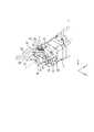
図3は、ブラケット10の内部構成を示した図である。図3においては、ブラケット10、カバー60、爪部材30b及び30cについては図示を省略してある。尚、図3においては回転軸40を簡略化して示している。また、図3では、支持部材20bについては理解を容易にするために揺動部材50から引き離して示している。図4A及び図4Bは、回転軸40の外観図である。図5A~図5Cは、揺動部材50の外観図である。最初に回転軸40について説明する。回転軸40は、モータ3の本体から突出した先端側の外周部にウォームギヤ部41が形成されており、貫通孔43を有した中空軸状に形成されている。ウォームギヤ部41は回転軸40を切削加工などして形成するほか、円筒状部材にウォームギヤ部41を形成したもの(図示していない)を回転軸40に嵌合するなどしてもよい。最終的に回転軸40の外周部にウォームギヤ部41が一体に設けられた構造となればよい。貫通孔43は、回転軸40の回転中心を軸方向に貫通している。貫通孔43の径は、回転軸40の長手方向で一定であるがこれに限定されない。回転軸40の軸方向での中心から基端側には、外径が一定である円筒外周面45が形成され、円筒外周面45には、モータ3を構成する不図示の永久磁石等が固定される。回転軸40は、例えばステンレスなどの金属製であるがこれに限定されない。FIG. 3 is a diagram showing the internal configuration of the
このように回転軸40が中空軸状に形成されているため、図2に示すように、回転軸40の貫通孔43とカバー60の開口61とは連通しており、これらの内部に、例えば把持対象物を撮影するカメラや、貫通孔43及び開口61を介して把持対象物に向けてエアーを噴射又は吸引可能なエアー吸引噴出装置等を実装するなどして多機能化を図ることができる。また、回転軸40は中空軸状であるため軽量化されており、これによりロボットハンド1全体の重量も軽量化されている。さらには、モータ3の発熱や、後述するウォームギヤ部41とウォームホイール部51との噛み合いによる摩擦熱等を適切に放熱することができる。Since the rotating
揺動部材50は、所定の厚みを有した略扇状である。厚み方向に貫通した中心孔53が形成されている。中心孔53には、図3に示すように、揺動部材50の厚み方向に貫通するように支持ピンP3が圧入される。支持ピンP3の一端は、図3に示した支持部材20bの保持孔23内に挿入される不図示の軸受により回転可能に支持される。支持部材20aについても同様に支持ピンP3の他端を回転可能に支持している。揺動部材50は、例えば鉄系の金属製であるがこれに限定されない。The
中心孔53を中心として円弧状に形成された部位には、複数の歯を有したウォームホイール部51が形成されている。ウォームホイール部51は、中心孔53を中心とした所定の角度範囲内に形成されている。爪部材30a~30cを開くことができる角度に対してウォームホイール部51が形成されている角度は、歯車の噛み合いを確保できるように十分大きくする必要がある。図2においてウォームギヤ部41とウォームホイール部51との噛み合う範囲は、約40°である。ウォームホイール部51をほぼ100°にわたって形成することで、図1から図3に開示したロボットハンド1においては、閉じた状態を0°とすると爪部材30a~30cは回転軸の中心線である中心軸心A1に対してそれぞれほぼ60°まで開くようにすることができる。さらにはウォームホイール部51を130°近く形成(図示していない)すれば爪部材30a~30cを中心軸心A1に対して其々ほぼ90°まで開くようにすることもできる。くわえて、後述する面59を設けず、後述する面56の面積を小さくすることによってウォームホイール部51を270°程度まで形成(図示していない)すれば、爪部材30a~30cを最大で180°以上に開くことができ、ロボットハンド1の外縁部に設けた溝(図示していない)などに収納する構造とすることも可能である。これら例示した数値はあくまでも本実施例についてのものであり、噛み合い量(前述の例では40°)は要求仕様に基づいたギヤの設計パラメータによって影響を受けるので、設計によっては爪部材30a~30cの開閉可能範囲が前述のものより大きいまたは小さい場合もありうる。また、図5に示すウォームホイール部51に対して、中心孔53を中心とした外周方向に連続して面56及び59が形成されている。面56及び59は、互いに略直交している。面56及び59には、ウォームホイール部51と異なり歯は形成されていない。このように、揺動部材50は、外周全域にわたって歯が設けられているわけではなく、外周の一部にウォームホイール部51が形成されているため、小型化が図られている。A
ウォームホイール部51は、図2及び図3に示すように、回転軸40のウォームギヤ部41と噛み合っている。これにより回転軸40が回転すると揺動部材50が支持ピンP3を支点として揺動し、これにより爪部材30aを開閉させることができる。同様に、爪部材30b及び30cを揺動するための揺動部材のウォームホイール部も回転軸40のウォームギヤ部41に噛み合っている。これにより、回転軸40が回転することにより3つの爪部材30a~30cが開閉し、把持対象物を把持することができる。また、モータ3はステッピングモータであるため、回転軸40を所定の回転角度位置で停止させることが可能である。このため、爪部材30a~30cのそれぞれを、揺動範囲内の所定位置に停止させることができる。As shown in FIGS. 2 and 3, the
ここで、ウォームギヤを用いることによる効果を説明する。ウォームギヤ部41とウォームホイール部51とが噛み合うウォームギヤとしているため、例えば平歯車同士が噛み合うような動力伝達機構を用いる場合と比較して、小型であって且つ大きな減速比を実現できる。これにより、小型であって且つ爪部材30a~30cの把持力を強力となるように確保することができる。また、大きな減速比を実現できることにより、爪部材30a~30cの開閉動作の位置精度を向上させることができる。さらに、モータ3の回転軸40にウォームギヤ部41が一体的に形成されているため、回転軸とウォームギヤとを別体に設けた場合と比較して小型化に有利である。くわえて、ウォームギヤ部41とウォームホイール部51による減速比が大きくなるようウォームギヤの進み角を小さくすることによりセルフロック作用が働く。このため、爪部材30a~30cの何れかに外力が加わっても、ウォームホイール部51からウォームギヤ部41へ伝達された外力は回転軸40を回転させることができないため、爪部材30a~30cの位置ずれを抑制できる。これにより、モータ3が無通電状態であっても、爪部材30a~30cを所定位置に維持することができ、ワーク(把持対象物)を把持した後にモータ3への電力供給を絶った場合でも把持状態を維持することができる。すなわち、無動力把持が実現できることより省エネルギー性に優れる上に、不意の停電などでワークの把持が解除されないことより安全性も高いことになる。Here, the effect of using the worm gear will be explained. Since the
面56には、凸部57が形成されており、図3に示すように爪部材30aの基端部に形成された凹部と係合している。また、面56には、凸部57を挟むように2つのネジ孔58が形成されており、上述したネジSが螺合する。ここで、ブラケット10は上述したネジSの頭部を露出するように形成されている。このような構造とすることで、ネジSを容易に取り外すことができ、爪部材30aを容易に交換することが可能となり、摩耗や破損によって取り換える場合やワーク(把持対象物)の種類によって付け替える場合などで作業工数を低減することが可能となる。このように爪部材30aの交換作業性が向上している。爪部材30aの交換作業性が高いということはロボットハンド1の組立作業性も高いということであり、組立工数を削減できることから生産コスト低減に寄与する。尚、他の爪部材30b及び30cも同様である。また、ブラケット10は上述したネジSの頭部を露出するように形成されているため、ロボットハンド1は小型化され、詳細には、中心軸心A1を中心とした径方向に小型化されている。ネジSは、第1固定部材の一例である。A
また、爪部材30aは、揺動部材50の揺動中心を介して回転軸40とは反対側に設けられた揺動部材50の面56に固定されている。換言すれば、爪部材30aの基端部は、揺動部材50の揺動中心よりも、中心軸心A1を中心とした径方向の外側に固定されている。即ち、爪部材30aの基端部と中心軸心A1との間の間隔が広く確保されており、他の爪部材30b及び30cについても同様である。このため、大きな部材を把持することができ、把持可能な対象物の範囲が拡大している。このように、ロボットハンド1としては小型化を図りながら、大きな部材をも把持することができる。Further, the
揺動部材50の扇状の側面52aには、中心孔53を中心とした円弧状の規制溝55が形成されている。また、図3に示すように支持部材20bは略直方形状であって、揺動部材50の側面52aに対向する面に嵌合孔25が形成されており、嵌合孔25には規制ピンP5の基端部が圧入される。また、規制ピンP5の先端は、揺動部材50の規制溝55内を移動可能に挿入される。即ち、規制ピンP5の外径は、規制溝55の幅よりも小さく形成されている。揺動部材50が支持ピンP3を支点として揺動することにより、規制ピンP5は規制溝55内を相対移動する。ここで爪部材30aが開くように揺動部材50が一方向に揺動していると、規制ピンP5が規制溝55の一端に当接する。これにより、揺動部材50のその方向でのそれ以上の揺動が規制される。同様に、爪部材30aが閉じるように揺動部材50が反対方向に揺動していると、規制ピンP5は規制溝55の他端に当接する。これにより、揺動部材50のその方向でのそれ以上の揺動が規制される。このようにして、爪部材30aの揺動範囲は規制されている。規制ピンP5と規制溝55によって揺動範囲を規制する構造とすることで、ロボットハンド1の保守作業者が爪部材30aを交換する際に誤って揺動部材50を動かしてしまった場合にウォームギヤ部41とウォームホイール部51との噛み合いが外れる失敗を防ぐことができる。尚、図5A~図5Cに示した、揺動部材50の、規制溝55が形成された側面52aとは反対側の側面にも、同様の規制溝が形成されており、支持部材20aが保持した規制ピンとこの規制溝とにより、揺動部材50の揺動範囲が規制されている。爪部材30b及び30cも同様の構成により揺動範囲が規制される。規制ピンP5及び規制溝55は、規制部の一例である。規制ピンP5は規制突部の一例である。規制ピンP5とその先端が移動する規制溝55は揺動部材50の両側面(側面52aとその反対側の側面)に設ける必要はなく、どちらか一方の側面であってもよい。An arc-shaped
また、図2及び図3に示すように、支持部材20a及び20bのそれぞれは、ブラケット10にネジTにより固定されている。ブラケット10は、ネジTの頭部を露出するように形成されている。このため、ネジTを取り外して支持部材20a及び20bをブラケット10から取り外すことにより、揺動部材50を容易にブラケット10から取り外すことができる。結果として、揺動部材50の交換作業性が向上している。例えば、ウォームホイール部51が摩耗した場合にこのような揺動部材50の交換が必要となることがあるが、このような際に上記構成は有効である。尚、他の爪部材30b及び30cに対応した支持部材も同様である。ネジTは第2固定部材の一例である。Further, as shown in FIGS. 2 and 3, each of the
ウォームギヤ部41及びウォームホイール部51は、一般的な平歯車同士の噛み合いとは異なり、摺動接触により双方が回転する。このため一般的には、摺動のしやすさ等を考慮して、出力側のギヤの金属材質は入力側のギヤの金属材質よりも軟質なものが用いられる。このため、出力側のギヤの方が入力側のギヤよりも摩耗しやすい。本実施例では、上述したように、出力側のウォームホイール部51の交換が容易であるため、ウォームホイール部51にウォームギヤ部41よりも軟質な材質を用いても、ウォームホイール部51が摩耗した場合には容易に揺動部材50を交換することができる。また、揺動部材50の交換作業性が高いということは生産時の組立作業性も高いということを意味し、組立工数を削減できることから生産コスト低減に寄与している。The
このように、頭部を露出するように形成されているネジTで支持部材20a及び20bがブラケット10に固定されていることから、揺動部材50の交換作業性も組立作業性も高い。このことより、揺動部材50をロボットハンド1へ組み付ける際の調整も容易となる。ウォームギヤ部41やウォームホイール部51などの歯車部材の仕上がりやブラケット10などの寸法にはバラツキが存在し、これらによって各歯車の中心間距離にもバラツキが生じる。これらのバラツキを考慮してロボットハンド1の設計を行うと、揺動部材50のバックラッシが大きくなる。一方、ロボットハンド1の爪部材30a~30cの位置精度を向上するため揺動部材のバックラッシはなるべく小さくすることが求められる。このような二律背反を解決するために、支持部材20a及び20bとブラケット10との間にシムを挟み込んで、中心軸心A1から径方向における支持部材20a及び20bの距離を調整することで揺動部材50(ウォームギヤ部41とウォームホイール部51)のバックラッシを低減し、ロボットハンド1の組み上がり精度が向上するよう導くことが可能となる。Since the
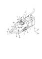
図6はシムの一例を示すための部分斜視図であり、主に支持部材20a及び20b、揺動部材50、爪部材30a、ネジT、シム21を表しており、それ以外のものは省略している。また、支持部材20a及び20bは透明に表現している。図6より前の図では説明を簡略化するためにネジTは支持部材20a及び20bのそれぞれに1つであったが、図6ではそれぞれ2つ備えている。支持部材20a及び20bはブラケット10(図6では図示していない)にネジTによって固定されるが、図6ではブラケット10と接する側を上としている。シム21は金属製の薄板であり、ネジTを通すための孔が2つ穿孔されている。図6においては、シム21の存在を明確にするための一例として、シム21は支持部材20bの側に1枚のみ設け、支持部材20aの側には設けていない状態としている。実際には、調整のために複数枚を重ねて設けることや、支持部材20a側と支持部材20b側とで異なる枚数とすることや、支持部材20a側と支持部材20b側とで同じ枚数とすることも可能である。このような調整は生産時の組立においても揺動部材50の交換においても容易に行うことができ、本発明のように頭部を露出するように形成されているネジTで支持部材20a及び20bがブラケット10に固定されていることを特徴とすることによって実現が可能となる。FIG. 6 is a partial perspective view for showing an example of the shim, and mainly shows the
前述の通り、揺動部材50は所定の厚みを有した略扇状であり、厚み方向に貫通した中心孔53が形成されており、中心孔53を中心として円弧状に形成された部位にはウォームホイール部51が形成されている。そして、ウォームホイール部51に対して中心孔53を中心とした外周方向に面56が形成されており、面56には凸部57が形成されており、爪部材30aの基端部に形成された凹部と係合している。このことより、爪部材30aの基端部は、中心軸心A1からみてウォームギヤ部41とウォームホイール部51の噛み合っている箇所の径方向外周側、すなわち略円柱状のブラケット10の側面外縁近傍に位置することを意味する。ブラケット10の先端側には円板状のカバー60が設けられているため、把持対象物に対してウォームギヤ部41とウォームホイール部51の噛み合っている箇所が露出しないようになっている。このことにより、ウォームギヤに塗布されている潤滑剤や噛み合いの摩耗によって生じる金属粉などが直接に把持対象物へ飛散することを防いでいる。As described above, the
一般にロボットハンドは、台上に載置された把持対象物を直上から把持する動作を行うことが多い。よって、ロボットハンドから把持対象物への不要な汚損に留意する必要があり、ロボットハンド内部の汚損物質がロボットハンド先端側の隙間を通って把持対象物に到達することを防止することが好ましい。本実施例のように、爪部材30a~30cの基端部がロボットハンド1のブラケット10の側面外縁近傍に位置するようにすることで、ロボットハンド1の先端側を単純なカバーで覆うことが可能となり、ロボットハンド1の内部の汚損物質が把持対象物へ到達することを抑制できる。なお、カバー60には開口61が形成されているが、これは回転軸40を中空軸状にした際の貫通孔43を介して多機能化するためのものであり、ロボットハンド1の内部の汚損物質を漏洩しない構造となっている。また、ロボットハンド1の内部の汚損物質を漏洩しない構造であることにより、ロボットハンド1の外部から塵埃が侵入することを低減する機能も持つ。ウォームギヤ部41とウォームホイール部51との噛み合い部へ異物が侵入しないようにすることで、ロボットハンド1の耐久性を向上することができる。In general, the robot hand often performs the operation of gripping the gripping object placed on the table from directly above. Therefore, it is necessary to pay attention to unnecessary contamination from the robot hand to the gripping object, and it is preferable to prevent the polluted substance inside the robot hand from reaching the gripping object through the gap on the tip side of the robot hand. As in the present embodiment, the tip end side of the robot hand 1 can be covered with a simple cover by locating the base end portions of the
尚、本実施例のように3つの爪部材30a~30cを用いるロボットハンド1の場合には、ウォームギヤ部41の条数を3の倍数にしてもよい。ウォームギヤ部41の条数が1の場合、爪部材30a~30cと組み合わされるウォームホイール部51はそれぞれの歯が相対的に120°ずつ位相が異なったものを必要とする。すなわち、3種類のウォームホイール部51が必要となってしまう。これに対し、ウォームギヤ部41の条数を3の倍数にすると、前述の爪部材30a~30cと組み合わされるウォームホイール部51は全て同じ形状のものを使用することが可能となる。これによりウォームホイール部51の形状を統一できコストダウンとなるうえに、組付け時の作業ミスが無くなるなどの副次的な効果も発生する。また、同様の理由により、2つの爪部材を用いるロボットハンドの場合には、ウォームギヤ部41の条数を2の倍数にしてもよい。更に、3つの爪部材を用いるロボットハンドと2つの爪部材を用いるロボットハンドとで回転軸40を共通化するために、ウォームギヤ部41の条数を6の倍数にしてもよい。即ち、m(mは2以上の整数)対の爪部材及び揺動部材を備えている場合には、ウォームギヤ部の条数は、mの倍数であればよい。In the case of the robot hand 1 using the three
上記実施例では、揺動する揺動部材50側に規制溝55が形成され、揺動しない支持部材20bに規制ピンP5が固定されていたがこれに限定されない。例えば、揺動部材50の側面52a上の中心孔53から径方向に離れた位置に規制ピンP5を固定し、この側面52aと対向する支持部材20bの面に、規制ピンP5が内部を移動可能であって規制ピンP5の移動範囲を規制する規制溝を設けてもよい。このように、揺動部材50の交換やロボットハンド1の組立を阻害しない範囲で、規制ピンP5と規制溝との関係を逆にすることも可能である。In the above embodiment, the
上記実施例では、爪部材30aと揺動部材50とは別体であったが一体に形成してもよい。この場合、前述の「m(mは2以上の整数)対の爪部材及び揺動部材」は「m(mは2以上の整数)個の爪部材と一体な揺動部材」となる。爪部材30b及び30cについても同様である。支持部材20a及び20bは、ブラケット10とは別体であるがこれに限定されず、揺動部材50の交換やロボットハンド1の組立を阻害しない範囲で支持部材20a及び20bのどちらか一方がブラケット10と一体に形成されていてもよい。この場合、ブラケット10と一体に形成されていない支持部材の側で前述のシム21による調整を行うことができる。In the above embodiment, the
尚、カムやカムフォロアを用いて爪部材を駆動するタイプのロボットハンドと比較すると、上記実施例のロボットハンド1では、カムやカムフォロアのように専用に設計する必要がなく、以前より世間で広く利用されてきた知見の蓄積を有している技術であるウォームギヤ部41及びウォームホイール部51を用いるため、低コスト化が達成されている。また、カムやカムフォロアを用いた場合よりも、耐荷重性や耐久性が向上している。Compared to a robot hand of the type that drives a claw member using a cam or cam follower, the robot hand 1 of the above embodiment does not need to be specially designed like a cam or cam follower, and is widely used in the world than before. Since the
以上本発明の好ましい実施形態について詳述したが、本発明は係る特定の実施形態に限定されるものではなく、特許請求の範囲に記載された本発明の要旨の範囲内において、変形・変更が可能である。
Although the preferred embodiments of the present invention have been described in detail above, the present invention is not limited to the specific embodiments, and modifications and modifications can be made within the scope of the gist of the present invention described in the claims. It is possible.
Claims (8)
Translated fromJapanese前記回転軸の先端部を収容した収容部材と、
前記回転軸が回転することにより前記収容部材に対して揺動する複数の揺動部材と、
複数の前記揺動部材のそれぞれと共に揺動する複数の爪部材と、
を備え、
前記回転軸は、外周にウォームギヤ部が形成されており、
前記揺動部材は、外周の一部に前記ウォームギヤ部に噛み合うウォームホイール部と、外周の一部に当該揺動部材の揺動中心を介して前記回転軸とは反対側に設けられた固定面と、を含み、
前記爪部材は、第1固定部材により取り外し可能に前記固定面に固定され、
前記収容部材は、前記第1固定部材を取り外し可能に露出している、ロボットハンド。A motor with a rotating shaft and
An accommodating member accommodating the tip of the rotating shaft and
A plurality of swinging members that swing with respect to the accommodating member by rotating the rotating shaft,
A plurality of claw members that swing together with each of the plurality of swinging members,
With
The rotating shaft has a worm gear portion formed on the outer periphery thereof.
The swing member has a worm wheel portion that meshes with the worm gear portion on a part of the outer circumference, and a fixed surface provided on a part of the outer circumference on the opposite side of the rotation shaft via the swing center of the swing member. And, including
The claw member is detachably fixed to the fixing surface by the first fixing member.
The housing member is a robot hand in which the first fixing member is detachably exposed.
前記支持部材は、第2固定部材により取り外し可能に前記収容部材に固定され、
前記収容部材は、前記第2固定部材を取り外し可能に露出している、請求項1のロボットハンド。A support member for supporting the swing member is provided.
The support member is detachably fixed to the accommodating member by the second fixing member.
The robot hand according to claim 1, wherein the accommodating member is detachably exposed from the second fixing member.
前記ウォームギヤ部の条数は、前記mの倍数である、請求項1乃至6の何れかのロボットハンド。The claw member and the swing member of m (m is an integer of 2 or more) are provided.
The robot hand according to any one of claims 1 to 6, wherein the number of threads of the worm gear portion is a multiple of m.
The robot hand according to any one of claims 1 to 7, wherein the rotating shaft has a hollow shaft shape.
Priority Applications (3)
| Application Number | Priority Date | Filing Date | Title |
|---|---|---|---|
| CN202080063137.5ACN114364499B (en) | 2019-11-29 | 2020-11-26 | Robot hand |
| US17/635,271US11691295B2 (en) | 2019-11-29 | 2020-11-26 | Robot hand |
| DE112020005867.0TDE112020005867T5 (en) | 2019-11-29 | 2020-11-26 | ROBOT HAND |
Applications Claiming Priority (4)
| Application Number | Priority Date | Filing Date | Title |
|---|---|---|---|
| JP2019-217305 | 2019-11-29 | ||
| JP2019217305 | 2019-11-29 | ||
| JP2020194376AJP6858301B1 (en) | 2019-11-29 | 2020-11-24 | Robot hand |
| JP2020-194376 | 2020-11-24 |
Publications (1)
| Publication Number | Publication Date |
|---|---|
| WO2021107039A1true WO2021107039A1 (en) | 2021-06-03 |
Family
ID=75378034
Family Applications (1)
| Application Number | Title | Priority Date | Filing Date |
|---|---|---|---|
| PCT/JP2020/044078CeasedWO2021107039A1 (en) | 2019-11-29 | 2020-11-26 | Robot hand |
Country Status (5)
| Country | Link |
|---|---|
| US (1) | US11691295B2 (en) |
| JP (1) | JP6858301B1 (en) |
| CN (1) | CN114364499B (en) |
| DE (1) | DE112020005867T5 (en) |
| WO (1) | WO2021107039A1 (en) |
Families Citing this family (3)
| Publication number | Priority date | Publication date | Assignee | Title |
|---|---|---|---|---|
| JP6858302B1 (en)* | 2019-11-29 | 2021-04-14 | シナノケンシ株式会社 | Robot hand |
| JP2022186604A (en)* | 2021-06-03 | 2022-12-15 | 株式会社コスメック | Detaching device |
| EP4342643A1 (en)* | 2022-09-26 | 2024-03-27 | Mettler-Toledo GmbH | Gripping appliance, and systems and method utilizing said gripping appliance |
Citations (11)
| Publication number | Priority date | Publication date | Assignee | Title |
|---|---|---|---|---|
| US3202449A (en)* | 1963-04-29 | 1965-08-24 | Jerome H Lemelson | Article manipulation device |
| JPS59167687U (en)* | 1983-04-11 | 1984-11-09 | ミカド金属工業株式会社 | gripping device |
| US4600357A (en)* | 1984-02-21 | 1986-07-15 | Heath Company | Gripper force sensor/controller for robotic arm |
| JP2000288971A (en)* | 1999-04-01 | 2000-10-17 | Souki Sekkei:Kk | Robot hand |
| CN201376279Y (en)* | 2009-04-08 | 2010-01-06 | 南京工程学院 | A robotic end effector |
| CN102431037A (en)* | 2011-09-30 | 2012-05-02 | 孙衡 | Bearing classification mechanical paw |
| US9782902B1 (en)* | 2016-06-29 | 2017-10-10 | Robotis Co., Ltd. | Gripper for robot hand capabel of adaptive grasp |
| JP3214039U (en)* | 2016-11-09 | 2017-12-14 | 高明▲てぃえ▼企業股▲ふん▼有限公司Gmt Global Inc. | Gripper with electric actuator with gap adjustment function |
| CN207788984U (en)* | 2017-12-15 | 2018-08-31 | 重庆市树德科技有限公司 | paw and teaching robot |
| US20190091876A1 (en)* | 2017-09-28 | 2019-03-28 | Ubtech Robotics Corp | Robotic hand |
| JP2019089186A (en)* | 2017-11-16 | 2019-06-13 | シナノケンシ株式会社 | Cam type hand mechanism |
Family Cites Families (18)
| Publication number | Priority date | Publication date | Assignee | Title |
|---|---|---|---|---|
| DE2607499C3 (en)* | 1976-02-25 | 1982-04-08 | Messerschmitt-Bölkow-Blohm GmbH, 8000 München | Drive device for the fingers of an artificial hand |
| JPS6076986A (en)* | 1983-09-30 | 1985-05-01 | 株式会社東芝 | Robot |
| JP2000325648A (en)* | 1999-05-24 | 2000-11-28 | Japan Servo Co Ltd | Prize gripping device of prize acquiring game machine |
| KR100451412B1 (en)* | 2001-11-09 | 2004-10-06 | 한국과학기술연구원 | Multi-fingered robot hand |
| ITBS20030049A1 (en)* | 2003-05-22 | 2004-11-23 | Gimatic Spa | ANGULAR PNEUMATIC CLAMP STRUCTURE. |
| JP2004358608A (en)* | 2003-06-05 | 2004-12-24 | Star Seiki Co Ltd | Holding device |
| US20080073922A1 (en)* | 2006-09-27 | 2008-03-27 | Oceaneering International, Inc. | Double Sided Rack Manipulator Jaw Actuator System |
| CN100595041C (en)* | 2008-05-22 | 2010-03-24 | 上海交通大学 | Large multi-sensor integrated electric gripper |
| US8414043B2 (en)* | 2008-10-21 | 2013-04-09 | Foster-Miller, Inc. | End effector for mobile remotely controlled robot |
| US8382177B2 (en)* | 2009-06-11 | 2013-02-26 | Re2, Inc. | Quick-change finger for robotic gripper |
| US20120177473A1 (en)* | 2011-01-12 | 2012-07-12 | Bradley Kenneth Smith | Gripper Assembly for Bottles for Pharmaceutical Prescriptions |
| US9075031B2 (en)* | 2011-10-11 | 2015-07-07 | Ortho-Clinical Diagnostics, Inc. | Apparatus for gripping and holding diagnostic cassettes |
| US20150151433A1 (en)* | 2013-12-02 | 2015-06-04 | Harris Corporation | Compact robotic gripper |
| US9718195B1 (en)* | 2016-06-09 | 2017-08-01 | X Development Llc | Cylindrical worm drive robotic gripper |
| CN107009380A (en)* | 2017-06-09 | 2017-08-04 | 成都众智优学教育咨询有限公司 | A kind of caliper brake manipulator |
| CN107598954A (en)* | 2017-09-28 | 2018-01-19 | 深圳市优必选科技有限公司 | a robot arm |
| JP6634059B2 (en)* | 2017-10-16 | 2020-01-22 | シナノケンシ株式会社 | Cam type hand mechanism |
| JP6858302B1 (en)* | 2019-11-29 | 2021-04-14 | シナノケンシ株式会社 | Robot hand |
- 2020
- 2020-11-24JPJP2020194376Apatent/JP6858301B1/enactiveActive
- 2020-11-26DEDE112020005867.0Tpatent/DE112020005867T5/enactivePending
- 2020-11-26CNCN202080063137.5Apatent/CN114364499B/enactiveActive
- 2020-11-26USUS17/635,271patent/US11691295B2/enactiveActive
- 2020-11-26WOPCT/JP2020/044078patent/WO2021107039A1/ennot_activeCeased
Patent Citations (11)
| Publication number | Priority date | Publication date | Assignee | Title |
|---|---|---|---|---|
| US3202449A (en)* | 1963-04-29 | 1965-08-24 | Jerome H Lemelson | Article manipulation device |
| JPS59167687U (en)* | 1983-04-11 | 1984-11-09 | ミカド金属工業株式会社 | gripping device |
| US4600357A (en)* | 1984-02-21 | 1986-07-15 | Heath Company | Gripper force sensor/controller for robotic arm |
| JP2000288971A (en)* | 1999-04-01 | 2000-10-17 | Souki Sekkei:Kk | Robot hand |
| CN201376279Y (en)* | 2009-04-08 | 2010-01-06 | 南京工程学院 | A robotic end effector |
| CN102431037A (en)* | 2011-09-30 | 2012-05-02 | 孙衡 | Bearing classification mechanical paw |
| US9782902B1 (en)* | 2016-06-29 | 2017-10-10 | Robotis Co., Ltd. | Gripper for robot hand capabel of adaptive grasp |
| JP3214039U (en)* | 2016-11-09 | 2017-12-14 | 高明▲てぃえ▼企業股▲ふん▼有限公司Gmt Global Inc. | Gripper with electric actuator with gap adjustment function |
| US20190091876A1 (en)* | 2017-09-28 | 2019-03-28 | Ubtech Robotics Corp | Robotic hand |
| JP2019089186A (en)* | 2017-11-16 | 2019-06-13 | シナノケンシ株式会社 | Cam type hand mechanism |
| CN207788984U (en)* | 2017-12-15 | 2018-08-31 | 重庆市树德科技有限公司 | paw and teaching robot |
Also Published As
| Publication number | Publication date |
|---|---|
| US20220288794A1 (en) | 2022-09-15 |
| CN114364499A (en) | 2022-04-15 |
| JP6858301B1 (en) | 2021-04-14 |
| CN114364499B (en) | 2024-05-24 |
| JP2021091083A (en) | 2021-06-17 |
| US11691295B2 (en) | 2023-07-04 |
| DE112020005867T5 (en) | 2022-10-13 |
Similar Documents
| Publication | Publication Date | Title |
|---|---|---|
| JP6858301B1 (en) | Robot hand | |
| JP4614879B2 (en) | Sealed worm gear type finger joint unit | |
| JP6790640B2 (en) | Valve opening / closing timing control device | |
| JP6858302B1 (en) | Robot hand | |
| WO2007077697A1 (en) | Finger unit for robot hand and method of assembling the same | |
| JPWO2017159841A1 (en) | Tube pump, rotation regulating parts, shaft body and shaft connection structure | |
| KR20190001542A (en) | Decelerator | |
| JPH0630339Y2 (en) | Reciprocating tool | |
| CN112976050A (en) | Joint structure of robot | |
| KR20150079607A (en) | Eccentric oscillation-type gear device | |
| JP2017115602A (en) | Valve timing control device | |
| KR101680419B1 (en) | Universal Link for Delta Robot | |
| JP2005133872A (en) | Actuator for valve | |
| JPWO2009151122A1 (en) | Power transmission device | |
| JP2004068850A (en) | Rotary shaft support mechanism | |
| KR102172816B1 (en) | Eccentric rocking type gear device | |
| JP4529090B2 (en) | Electric actuator | |
| WO2022039117A1 (en) | Linear motion device | |
| WO2006101014A1 (en) | Working tool | |
| JP2016048099A (en) | Eccentric oscillating gear device and torque adjusting method thereof | |
| EP0733434B1 (en) | Tool for cutting surface of workpiece in elliptic shape | |
| JP2013094904A (en) | Working tool | |
| JP2015158238A (en) | Simplified free type bidirectional clutch | |
| JP2004068964A (en) | Gear mechanism | |
| JP6594037B2 (en) | Balancer mechanism |
Legal Events
| Date | Code | Title | Description |
|---|---|---|---|
| 121 | Ep: the epo has been informed by wipo that ep was designated in this application | Ref document number:20891806 Country of ref document:EP Kind code of ref document:A1 | |
| 122 | Ep: pct application non-entry in european phase | Ref document number:20891806 Country of ref document:EP Kind code of ref document:A1 |