WO2021106590A1 - Video transmission device and display device - Google Patents
Video transmission device and display deviceDownload PDFInfo
- Publication number
- WO2021106590A1 WO2021106590A1PCT/JP2020/042200JP2020042200WWO2021106590A1WO 2021106590 A1WO2021106590 A1WO 2021106590A1JP 2020042200 WJP2020042200 WJP 2020042200WWO 2021106590 A1WO2021106590 A1WO 2021106590A1
- Authority
- WO
- WIPO (PCT)
- Prior art keywords
- information
- hmd
- unit
- video
- computer
- Prior art date
- Legal status (The legal status is an assumption and is not a legal conclusion. Google has not performed a legal analysis and makes no representation as to the accuracy of the status listed.)
- Ceased
Links
Images


Classifications
- H—ELECTRICITY
- H04—ELECTRIC COMMUNICATION TECHNIQUE
- H04N—PICTORIAL COMMUNICATION, e.g. TELEVISION
- H04N21/00—Selective content distribution, e.g. interactive television or video on demand [VOD]
- H04N21/20—Servers specifically adapted for the distribution of content, e.g. VOD servers; Operations thereof
- H04N21/23—Processing of content or additional data; Elementary server operations; Server middleware
- H04N21/234—Processing of video elementary streams, e.g. splicing of video streams or manipulating encoded video stream scene graphs
- H04N21/2343—Processing of video elementary streams, e.g. splicing of video streams or manipulating encoded video stream scene graphs involving reformatting operations of video signals for distribution or compliance with end-user requests or end-user device requirements
- H—ELECTRICITY
- H04—ELECTRIC COMMUNICATION TECHNIQUE
- H04N—PICTORIAL COMMUNICATION, e.g. TELEVISION
- H04N21/00—Selective content distribution, e.g. interactive television or video on demand [VOD]
- H04N21/20—Servers specifically adapted for the distribution of content, e.g. VOD servers; Operations thereof
- H04N21/25—Management operations performed by the server for facilitating the content distribution or administrating data related to end-users or client devices, e.g. end-user or client device authentication, learning user preferences for recommending movies
- H04N21/258—Client or end-user data management, e.g. managing client capabilities, user preferences or demographics, processing of multiple end-users preferences to derive collaborative data
- H04N21/25808—Management of client data
- H04N21/25833—Management of client data involving client hardware characteristics, e.g. manufacturer, processing or storage capabilities
- G—PHYSICS
- G06—COMPUTING OR CALCULATING; COUNTING
- G06F—ELECTRIC DIGITAL DATA PROCESSING
- G06F3/00—Input arrangements for transferring data to be processed into a form capable of being handled by the computer; Output arrangements for transferring data from processing unit to output unit, e.g. interface arrangements
- G06F3/01—Input arrangements or combined input and output arrangements for interaction between user and computer
- G06F3/011—Arrangements for interaction with the human body, e.g. for user immersion in virtual reality
- G06F3/012—Head tracking input arrangements
- G—PHYSICS
- G06—COMPUTING OR CALCULATING; COUNTING
- G06F—ELECTRIC DIGITAL DATA PROCESSING
- G06F3/00—Input arrangements for transferring data to be processed into a form capable of being handled by the computer; Output arrangements for transferring data from processing unit to output unit, e.g. interface arrangements
- G06F3/14—Digital output to display device ; Cooperation and interconnection of the display device with other functional units
- G06F3/147—Digital output to display device ; Cooperation and interconnection of the display device with other functional units using display panels
- G—PHYSICS
- G09—EDUCATION; CRYPTOGRAPHY; DISPLAY; ADVERTISING; SEALS
- G09G—ARRANGEMENTS OR CIRCUITS FOR CONTROL OF INDICATING DEVICES USING STATIC MEANS TO PRESENT VARIABLE INFORMATION
- G09G5/00—Control arrangements or circuits for visual indicators common to cathode-ray tube indicators and other visual indicators
- G09G5/36—Control arrangements or circuits for visual indicators common to cathode-ray tube indicators and other visual indicators characterised by the display of a graphic pattern, e.g. using an all-points-addressable [APA] memory
- G09G5/38—Control arrangements or circuits for visual indicators common to cathode-ray tube indicators and other visual indicators characterised by the display of a graphic pattern, e.g. using an all-points-addressable [APA] memory with means for controlling the display position
- H—ELECTRICITY
- H04—ELECTRIC COMMUNICATION TECHNIQUE
- H04N—PICTORIAL COMMUNICATION, e.g. TELEVISION
- H04N21/00—Selective content distribution, e.g. interactive television or video on demand [VOD]
- H04N21/60—Network structure or processes for video distribution between server and client or between remote clients; Control signalling between clients, server and network components; Transmission of management data between server and client, e.g. sending from server to client commands for recording incoming content stream; Communication details between server and client
- H04N21/63—Control signaling related to video distribution between client, server and network components; Network processes for video distribution between server and clients or between remote clients, e.g. transmitting basic layer and enhancement layers over different transmission paths, setting up a peer-to-peer communication via Internet between remote STB's; Communication protocols; Addressing
- H04N21/647—Control signaling between network components and server or clients; Network processes for video distribution between server and clients, e.g. controlling the quality of the video stream, by dropping packets, protecting content from unauthorised alteration within the network, monitoring of network load, bridging between two different networks, e.g. between IP and wireless
- H04N21/64723—Monitoring of network processes or resources, e.g. monitoring of network load
- H04N21/64738—Monitoring network characteristics, e.g. bandwidth, congestion level
- H—ELECTRICITY
- H04—ELECTRIC COMMUNICATION TECHNIQUE
- H04N—PICTORIAL COMMUNICATION, e.g. TELEVISION
- H04N21/00—Selective content distribution, e.g. interactive television or video on demand [VOD]
- H04N21/60—Network structure or processes for video distribution between server and client or between remote clients; Control signalling between clients, server and network components; Transmission of management data between server and client, e.g. sending from server to client commands for recording incoming content stream; Communication details between server and client
- H04N21/65—Transmission of management data between client and server
- H04N21/654—Transmission by server directed to the client
- H04N21/6547—Transmission by server directed to the client comprising parameters, e.g. for client setup
- H—ELECTRICITY
- H04—ELECTRIC COMMUNICATION TECHNIQUE
- H04N—PICTORIAL COMMUNICATION, e.g. TELEVISION
- H04N21/00—Selective content distribution, e.g. interactive television or video on demand [VOD]
- H04N21/60—Network structure or processes for video distribution between server and client or between remote clients; Control signalling between clients, server and network components; Transmission of management data between server and client, e.g. sending from server to client commands for recording incoming content stream; Communication details between server and client
- H04N21/65—Transmission of management data between client and server
- H04N21/658—Transmission by the client directed to the server
- H04N21/6587—Control parameters, e.g. trick play commands, viewpoint selection
- H—ELECTRICITY
- H04—ELECTRIC COMMUNICATION TECHNIQUE
- H04N—PICTORIAL COMMUNICATION, e.g. TELEVISION
- H04N21/00—Selective content distribution, e.g. interactive television or video on demand [VOD]
- H04N21/80—Generation or processing of content or additional data by content creator independently of the distribution process; Content per se
- H04N21/81—Monomedia components thereof
- H04N21/816—Monomedia components thereof involving special video data, e.g 3D video
- G—PHYSICS
- G09—EDUCATION; CRYPTOGRAPHY; DISPLAY; ADVERTISING; SEALS
- G09G—ARRANGEMENTS OR CIRCUITS FOR CONTROL OF INDICATING DEVICES USING STATIC MEANS TO PRESENT VARIABLE INFORMATION
- G09G2354/00—Aspects of interface with display user
- G—PHYSICS
- G09—EDUCATION; CRYPTOGRAPHY; DISPLAY; ADVERTISING; SEALS
- G09G—ARRANGEMENTS OR CIRCUITS FOR CONTROL OF INDICATING DEVICES USING STATIC MEANS TO PRESENT VARIABLE INFORMATION
- G09G2370/00—Aspects of data communication
- G09G2370/04—Exchange of auxiliary data, i.e. other than image data, between monitor and graphics controller
- G—PHYSICS
- G09—EDUCATION; CRYPTOGRAPHY; DISPLAY; ADVERTISING; SEALS
- G09G—ARRANGEMENTS OR CIRCUITS FOR CONTROL OF INDICATING DEVICES USING STATIC MEANS TO PRESENT VARIABLE INFORMATION
- G09G2370/00—Aspects of data communication
- G09G2370/16—Use of wireless transmission of display information
Definitions
- the present technologyrelates to a video transmission device and a display device, and more particularly to a video transmission device and a display device that wirelessly transmits a video according to the state of the display device from the video transmission device.
- Patent Document 1discloses a technique for correcting an image in real time in an HMD when the moving distance of the HMD exceeds a predetermined threshold value by using an inertial sensor built in the HMD (Head Mounted Display). There is.
- This technologywas made in view of such a situation, and is intended to enable wireless transmission of video according to the state of the display device from the video transmission device and reduce the processing capacity of the display device.
- the video transmission device of the first aspect of the present technologyis generated by a video generation unit that converts video information based on inertial information transmitted from the display device to generate a plurality of different converted video information, and the video generation unit. It is a video transmission device having a wireless communication unit that transmits a plurality of different converted video information to the display device by different beams.
- the video informationis converted based on the inertial information transmitted from the display device, and a plurality of different converted video information is generated.
- a plurality of different converted video information generatedis transmitted to the display device by beams different from each other.
- the display device on the second aspect of the present technologyincludes a wireless communication unit that demodulates a part of a plurality of beams arriving from the video transmission device, and video information obtained by demodulating the beam by the wireless communication unit. It is a display device having a display for displaying the above, a position module for acquiring inertial information by measurement, and an inertial information communication unit for transmitting the inertial information acquired by the position module to the video transmission device.
- a part of a plurality of beams arriving from the video transmitting deviceis demodulated, and the video information obtained by demodulation is displayed.
- Inertia informationis acquired by measurement, and the acquired inertia information is transmitted to the video transmission device.
- Embodiment 1It is a block diagram which showed the structural example of one Embodiment of the information processing system to which this technology is applied. It is a block diagram which showed the 1st configuration example of the computer of FIG. It is a block diagram which showed the 2nd configuration example of the computer of FIG. It is a block diagram which showed the structural example of the HMD of FIG. It is a sequence diagram which illustrated the outline of the process of Embodiment 1 of an information processing system. It is a figure which showed the state when a plurality of coding information corresponding to the future state of the HMD predicted by the computer is transmitted from the computer to the HMD by a plurality of different beams. It is an overall sequence diagram in Embodiment 1 of an information processing system.
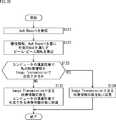
- Embodiment 2It is an overall sequence diagram in Embodiment 2 of the information processing system 11. It is a flowchart explaining the method of determining the beam and the number of beams to be simultaneously transmitted in the Image Transmission of the phase P3 of the second embodiment. It is a block diagram which shows the configuration example of the hardware of the computer which executes a series of processing by a program.
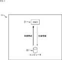
- FIG. 1is a block diagram showing a configuration example of an embodiment of an information processing system to which the present technology is applied.
- the information processing system 11has an HMD (Head Mounted Display) 21 and a computer 22.
- HMDHead Mounted Display
- the HMD21is a portable device worn around the head, and a display located close to both eyes displays an image according to the user's condition.
- the computer 22generates video information (image information) to be displayed on the HMD 21 and transfers the video information to the HMD 21.
- the HMD 21is connected to the computer 22 by wireless transmission.
- Control information including inertial informationis wirelessly transmitted from the HMD 21, and the computer 22 generates an image to be displayed on the HMD 21 based on the control information sent from the HMD 21.
- the difference in wireless communication method between video information and control informationdoes not matter, but for example, for wireless transmission of video information that requires a high transmission rate, a communication method such as a wireless standard using the 60 GHz band is used, and low transmission is performed.
- a wireless standard communication methodsuch as Bluetooth (registered trademark) is used for wireless transmission of control information whose rate is sufficient.
- the computer 22may be any general-purpose or dedicated computer, and may be, for example, a game console, a personal computer, a mobile device, or the like, but is not limited thereto. Further, except for a part of the computer 22, for example, a part that wirelessly communicates with the HMD 21, even if it is placed in a remote place away from the HMD 21 such as a server connected through a network such as the Internet or a computer in a data center. Good. Further, a part of the computer 22 may be constructed by a computing service (cloud service or the like) provided through the network.
- a computing servicecloud service or the like
- FIG. 2is a block diagram showing a first configuration example of the computer 22 of FIG.
- the computer 22includes a wireless communication unit 31, an encoder unit 32, a control unit 33, a video generation unit 34, and a tracker 35.
- the wireless communication unit 31performs wireless communication with the HMD 21.
- the wireless communication unit 31includes an image transmission communication unit 41 and an inertial measurement communication unit 42.
- the image transmission communication unit 41wirelessly communicates with the HMD 21 using one or two or more beams (multi-beams).
- the beamshows the directivity of radio waves and is dynamically formed by a phase shifter or digital calculation. Further, the image transmission communication unit 41 can generate a plurality of beams having different radiation directions, and can transmit different video information for each beam.
- video information (image information) to be displayed on the HMD 21is transmitted from the image transmission communication unit 41 to the HMD 21.
- control information necessary for setting the beam of the image transmission communication unit 41may be transmitted from the image transmission communication unit 41 to the HMD 21 or from the HMD 21 to the image transmission communication unit 41, for example.
- the inertial measurement communication unit 42acquires inertial information obtained by a plurality of inertial sensors provided in the HMD 21 from the HMD 21 (inertial measurement communication unit 92 described later) by wireless communication.
- the encoder unit 32encodes the video information generated by the video generation unit 34.
- the control unit 33comprehensively controls the entire computer 22. Further, the control unit 33 supplies the information necessary for generating the video information to the video generation unit 34. Further, when the control unit 33 transmits the video information encoded by the encoder unit 32 from the image transmission communication unit 41 of the wireless communication unit 31 to the HMD 21, the image transmission communication unit 41 can generate a plurality of beams. Decide which of the beams should be used to transmit the video information.
- the video generation unit 34generates (renders) the video information to be displayed on the HMD 21 based on the information supplied from the control unit 33, and converts / corrects the generated video information based on the latest inertial information. Then, the video generation unit 34 supplies the converted video information to the encoder unit 32.
- the tracker 35is used to grasp the position of the HMD 21, and may be realized by, for example, a camera, LiDAR (Light Detection and Ranging), a radar, or the like, but is not limited to these, and is not necessarily a necessary element. is not it.
- the image generation unit 34visualizes information about an object or a figure given by the control unit 33 or another entity having image information as numerical data in, for example, three-dimensional graphics by rendering. Then, the video generation unit 34 further converts (corrects) the video information visualized by rendering into video information that conforms to (corresponds to) the future state of the HMD 21.
- the video generation unit 34converts the video information visualized by rendering into the original video information, and the video information visualized by rendering in accordance with the future state of the HMD 21 into the converted video information, the video generation unit 34.
- the video information (converted video information) encoded by the encoder unit 32is referred to as encoded information, and all of them are video information, but if necessary, the original video information, the converted video information, and the code are used. Which video information is used properly.
- the future state of the HMD 21indicates the future state of the HMD 21 from the time when the original video information is converted into the converted video information by the video generation unit 34. Further, the future state of the HMD 21 indicates a state when the HMD 21 receives the coded information generated from the original video information, and includes, but is not limited to, for example, the position and orientation of the HMD 21.
- the control unit 33predicts the future position and attitude of the HMD 21 as the future state of the HMD 21, for example, based on the inertial information from the HMD 21. Further, the control unit 33 has a plurality of different front directions of the HMD 21 by giving a width to the prediction range regarding the direction (front direction) of the HMD 21 because it is difficult to accurately predict the rotation operation of the HMD 21. The state is predicted as the future state of the HMD 21.
- the video generation unit 34generates converted video information corresponding to each of the plurality of future states of the HMD 21 predicted by the control unit 33, and the plurality of states in which the front direction of the HMD 21 is different. Further, the prediction of the future state of the HMD 21 may be performed by the image generation unit 34.
- FIG. 3is a block diagram showing a second configuration example of the computer 22 of FIG.
- the parts corresponding to the first configuration example of the computer 22 in FIG. 2are designated by the same reference numerals, and the description thereof will be omitted.
- the computer 22 in FIG. 3has a computer remote unit 51 and a computer local unit 52.
- the computer remote unit 51includes an encoder unit 32, a video generation unit 34, a control unit 61, and a core communication unit 62
- the computer local unit 52includes a wireless communication unit 31, a tracker 35, a control unit 71, and a core. It has a communication unit 72.
- the computer 22 of FIG. 3is common to the case of FIG. 2 in that it has a wireless communication unit 31, an encoder unit 32, a video generation unit 34, and a tracker 35.
- the computer 22 in FIG. 3is entirely divided into a computer remote unit 51 and a computer local unit 52, and a control unit 61 and a control unit 71 are provided instead of the control unit 33 in FIG. , And the core communication unit 62 and the core communication unit 72 are newly provided, which is different from the case of FIG.
- the computer remote unit 51is, for example, a device placed in a remote location away from the HMD 21 and having a rendering function.
- the computer remote unit 51may be a server connected through a network such as the Internet, but the present invention is not limited to this. Further, the computer remote unit 51 does not necessarily have to be located at a location away from the HMD 21.
- the computer local unit 52is placed relatively close to the HMD 21 such as in the same building, and performs direct wireless communication with the HMD 21 on behalf of the computer 22.
- the computer local unit 52may be, for example, a wireless LAN (Local Area Network) access point or a cellular base station, but is not limited thereto.
- the control unit 61comprehensively controls the entire computer remote unit 51. Further, the control unit 61 executes substantially the same processing as the control unit 33 of FIG. However, the control unit 61 controls the core communication unit 62 and controls the wireless communication unit 31 and the tracker 35 of the computer local unit 52 via the control unit 71 of the computer local unit 52. It is different from the control unit 33 of 2.
- the control unit 71comprehensively controls the entire computer local unit 52. Further, the control unit 71 controls the wireless communication unit 31 and the tracker 35 in cooperation with the control unit 61 of the computer remote unit 51.
- the core communication unit 62 and the core communication unit 72communicate with each other and transmit information (video information, inertial information, etc.) between the computer remote unit 51 and the computer local unit 52.
- information transmission between the core communication unit 62 and the core communication unit 72is not limited to wired transmission such as optical fiber and wireless transmission.
- FIG. 4is a block diagram showing a configuration example of the HMD 21 of FIG.
- the HMD 21includes a wireless communication unit 81, a control unit 82, a position module group 83, a video generation unit 84, a storage unit 85, and a display 86.
- the wireless communication unit 81performs wireless communication with the wireless communication unit 31 (see FIGS. 2 and 3) of the computer 22.
- the wireless communication unit 81includes an image transmission communication unit 91 and an inertial measurement communication unit 92.
- the image transmission communication unit 91has an antenna for transmitting and receiving radio waves, and a beam that enhances reception sensitivity in a desired direction by appropriately synthesizing signals by a phase shifter or numerical calculation using a plurality of antennas. Can be formed. Further, the image transmission communication unit 91 generates a beam from an antenna having directivity, and uses the beam to transmit various information to the image transmission communication unit 41 (see FIGS. 2 and 3) of the wireless communication unit 31 in the computer 22. ).
- the image transmission communication unit 91arrives from a part of a plurality of beams emitted from the image transmission communication unit 41 of the computer 22, for example, from the front direction of the HMD 21 by forming a beam. Only the beam (or the beam having the largest received power) is demodulated, and the image information (encoding information) transmitted by the beam is received and supplied to the image generation unit 84. Further, control information and the like necessary for beam setting and the like are exchanged between the image transmission communication unit 91 and the image transmission communication unit 41 of the computer 22.
- the inertial measurement communication unit 92mainly transmits inertial information obtained by a plurality of inertial sensors provided in the HMD 21 to the inertial measurement communication unit 42 (see FIGS. 2 and 3) of the computer 22.
- the control unit 82comprehensively controls the entire processing of the HMD 21.
- the control unit 82supplies the wireless communication unit 81 with inertial information regarding the three-dimensional position and orientation of the HMD 21 obtained by the position module group 83, and causes the inertial measurement communication unit 92 to transmit the inertial information to the computer 22.
- the position module group 83acquires information (referred to as inertial information) regarding the three-dimensional position, attitude, and motion (angular velocity, etc.) of the HMD 21.
- the position module group 83may be composed of a magnetometer 101, a speedometer 102, a gyroscope 103, a GPS (Global Positioning System) 104, and the like, but the components are not limited thereto.
- the inertial informationmay be any information as long as it represents the state of the HMD 21.
- the video generation unit 84acquires the video information transmitted from the computer 22 and received by the image transmission communication unit 91 of the wireless communication unit 81.
- the video generation unit 84decodes the video information (encoding information) encoded by the encoder unit 32 (see FIGS. 2 and 3) of the computer 22 and then performs drawing processing to supply the video information to the storage unit 85.
- the storage unit 85temporarily stores the video information from the video generation unit 84 under the control of the control unit 82, and supplies the stored video information to the display 86.
- the display 86displays the video information from the storage unit 85 on the screen.
- each component in the HMD 21 in FIG. 4is an example, and for example, the positions of the video generation unit 84 and the storage unit 85 may be different.
- Embodiment 1The first embodiment of the information processing system 11 composed of the computer 22 of the second configuration example of FIG. 3 will be described in detail.
- the information processing system 11 composed of the computer 22 of the first configuration example of FIG. 2is defined as the second embodiment.
- the transmission of information between the computer remote unit 51 and the computer local unit 52is performed by communication between the core communication unit 62 and the core communication unit 72, whereas in the second embodiment.
- the differenceis that the transmission of information inside the computer 22 does not require the communication as in the first embodiment.
- FIG. 5is a sequence diagram illustrating an outline of the processing of the first embodiment of the information processing system 11.
- FIG. 5shows the timing of various processes performed in each of the computer remote unit 51, the computer local unit 52, and the HMD 21 corresponding to the time axis.
- the image generation unit 34visualizes the numerical data given by the control unit 61, for example, in 3D graphics, by rendering in the period from time t0 to time t2, and displays the image information on the HMD 21. Generates the original video information that is the basis of. Then, the video generation unit 34 converts the generated original video information into converted video information according to the state of the HMD 21 at a future time t5, for example. Conversion to converted video information includes, but is not limited to, trapezoidal conversion of a video (image) by rotation of the HMD 21, for example.
- the state of the HMD 21 at the time t5is the state of the HMD 21 predicted when the HMD 21 receives the coded information generated by the subsequent processing of the original video information generated at the time t2 by the image generation unit 34. It is a future state.
- the period from the time t2 to the time t5depends on the processing time (including the transmission time of the video information) of the processing performed after the original video information generated by the video generation unit 34 at the time t2.
- the control unit 61may obtain in advance the time (referred to as the video information transmission time) from the time when the video generation unit 34 generates the original video information until the HMD 21 receives the coded information for the original video information. Good, but not limited to this.
- the HMD 21when the HMD 21 receives the encoded information for the original video information generated by the video generation unit 34 at the start of the wireless connection between the computer 22 and the HMD 21 or at an appropriate timing after the wireless connection, the HMD 21 receives the coded information.
- the video information transmission timemay be actually measured based on the response information returned to the computer 22.
- the time t5is an example of a time obtained by adding the video information transmission time to the time t2 in which the video generation unit 34 generated the original video information, and the HMD 21 receives the encoded information for the original video information.
- the timecan be a time other than time t5.
- the control unit 61is based on the inertia information ⁇ (t) (t is the time before t1) from the HMD 21 to the latest (latest) already acquired from the HMD 21 at the time t2 when the image generation unit 34 generates the original video information.
- a plurality of future states of the HMD 21 at time t5are predicted, and a plurality of states having different front directions of the HMD 21 are predicted, and a plurality of predicted future states of the HMD 21 are supplied to the image generation unit 34.
- the inertia information ⁇ (t)indicates the inertia information measured by the position module group 83 of the HMD 21 at time t.
- the video generation unit 34may predict a plurality of future states of the HMD 21.
- the image generation unit 34is a plurality of future states of the HMD 21 at time t5, that is, a state of the HMD 21 predicted based on the inertial information ⁇ (t), and is a state of the HMD 21 that receives the video information. Converted video information according to each state is generated by video conversion to the original video information.
- the encoder unit 32independently encodes the converted video information corresponding to a plurality of future states of the HMD 21 generated by the video generation unit 34 into encoded information, and transmits the converted video information to the wireless communication unit 31 of the computer local unit 52. To do.
- the coded informationis transmitted to the computer local unit 52 via the core communication unit 62 and the core communication unit 72 (see FIG. 3).
- the wireless communication unit 31 (image transmission communication unit 41) of the computer local unit 52generates a plurality of beams # 1 to #N (N is 2 or more) having directivity, and each of the beams # 1 to #N.
- N in the beams # 1 to #Ncorresponds to the number of coding information supplied from the encoder unit 32, and corresponds to the number of a plurality of future states of the HMD 21 predicted by the control unit 61.
- Nis a number equal to or less than the maximum number of beams that can be generated by the wireless communication unit 31.
- the beams # 1 to #Nare those in which N beams selected from the beams that can be generated by the wireless communication unit 31 are assigned identification codes of # 1 to #N, respectively.
- Each beam # 1 to # Nhas a different radiation direction when radiated from the wireless communication unit 31. Further, each of the beams # 1 to # N may arrive at the position of the HMD 21 after being reflected by a wall surface or the like. Further, the arrival direction when each beam # 1 to # N arrives at the position of the HMD 21 is different for each beam # 1 to # N. Therefore, the received power of each beam received by the wireless communication unit 81 of the HMD 21 (communication unit 91 for image transmission, see FIG. 4) changes depending on the direction of the HMD 21 (front direction of the HMD 21), and becomes the received power between the beams. There is a difference.
- the control unit 61 of the computer remote unit 51assigns a beam to be transmitted to each of the plurality of coded information (hereinafter referred to as a transmission beam) from among the beams radiable from the wireless communication unit 31.
- a transmission beamFor example, the transmission beam (transmitting beam) arriving from the direction closest to the direction in which the received power of the HMD 21 in the assumed state is maximized.
- a beam that can be received in the assumed state)is assigned as a transmission beam that transmits the coded information generated corresponding to the assumed state.
- Information indicating the allocation of the transmission beam to each coded informationis referred to as beam allocation information.
- control unit 61supplies the beam allocation information to the wireless communication unit 31 via the control unit 71 of the computer local unit 52.
- the wireless communication unit 31transmits each of the plurality of coded information from the encoder unit 32 from the image transmission communication unit 41 to the HMD 21 by a transmission beam according to the beam allocation information from the control unit 61.
- the image transmission communication unit 41causes the HMD 21 to transmit each coded information based on each coded information by a transmission beam assigned to each.
- the coding information #i-jindicates the i-th frame of the coding information transmitted by the transmission beam j (j is 1 to N).
- a framerefers to a unit of image information or video information transmitted by subdividing one image or video.
- the wireless communication unit 31encodes the coded information #i-j (i is 1 to 1 to 1) that encodes the converted video information for one screen to be displayed on the HMD 21 until new coded information is given from the encoder unit 32. k) can be repeatedly transmitted to the HMD 21 on a frame-by-frame basis by the same transmission beam.
- each coded informationis transmitted to the HMD 21 for k frames is illustrated, but k may be a predetermined number, and the encoder unit 32 is new to the wireless communication unit 31. It may be the number of frames that can be repeatedly transmitted before the coding information is given.
- the HMD 21forms a beam (hereinafter referred to as a received beam) in which the image transmission communication unit 91 (see FIG. 4) of the wireless communication unit 81 uses a plurality of antennas to increase the received power in a specific direction.
- the image transmission communication unit 91forms, for example, a directional reception beam that maximizes the reception power for the transmission beam coming from the front direction of the HMD 21. It is assumed that the reception beam formed by the HMD 21 is formed so as not to have a gain equivalent to that in the desired direction other than the desired direction.
- the image transmission communication unit 91is a reception beam formed by the HMD 21 among the transmission beams of the plurality of beams # 1 to # N radiated from the wireless communication unit 31 (image transmission communication unit 41) of the computer local unit 52. Only the coded information transmitted by the transmission beam of the computer local unit 52 that maximizes the received power when received is received, but even if the optimum coded information is selected after receiving a plurality of coded information. Good.
- the coding information corresponding to the state closest to the actual state of the HMD 21 at the time t5is the HMD 21. It is transmitted to the HMD 21 by the transmitting beam arriving from the direction closest to the receiving beam to be formed.
- the wireless communication unit 81 of the HMD 21receives, for example, the transmission beam having the highest received power among the transmission beams arriving at the image transmission communication unit 91, and demodulates the coded information transmitted by the beam.
- the wireless communication unit 81has the coding information # 1- of the beams # 1 to # N radiated from the wireless communication unit 31 of the computer local unit 52 at time t5, which are transmitted by the beam #a. It indicates that a and # 2-a have been continuously received for two frames. Further, the wireless communication unit 81 continues to receive the coded information until the time t7.
- the wireless communication unit 81is encoded by the beam # m different from the beam #a by the time t7. The case where the information # km is received is illustrated.
- the coded information received by the wireless communication unit 31is subjected to decoding processing and drawing processing in the video generation unit 84 of FIG. 4, and the converted video information before being encoded by the encoder unit 32 of the computer remote unit 51 is obtained. It is temporarily stored in the storage unit 85. Then, the video information stored in the storage unit 85 is displayed on the display 86 from the time t8 when the drawing process of the coded information received in the period from the time t5 to the time t7 is completed.
- the HMD 21may perform drawing processing each time it receives coding information for one frame, and receive the coding information and drawing processing in parallel. Further, the control unit 61 (see FIG. 3) of the computer remote unit 51 predicted a plurality of future states of the HMD 21 at time t5 in the first embodiment, but the wireless communication unit 31 of the HMD 21 or the coded information. A plurality of states of the HMD 21 predicted in the period from the time t5 when the reception starts to the time t7 when the image generation unit 84 starts the drawing process may be predicted.
- Motion to Photon LatencyRepresents the delay time related to the display, and is mainly the sum of the transmission delay and the drawing delay. If the HMD 21 at the time t5 predicted by the computer remote unit 51 or the computer local unit 52 matches the state of the HMD 21 at the actual time t5, the perceived delay of the image displayed on the display 86 of the HMD 21 is Motion to Photon. Corresponds to Latency. That is, Motion to Photon Latency means the minimum value of the perceived delay.
- the image generation unit 34 of the computer remote unit 51will change to the state of HMD21 at time t1 based on the inertial information ⁇ (t1) at time t2 without predicting the future state of HMD21. Video conversion to the corresponding converted video information is performed. Therefore, the period from the time t1 at which the inertial information ⁇ (t1) is acquired to the time t8 at which the video information is displayed is the delay time for display.
- the HMD 21receives the video information according to the state, it is not necessary to correct the video information with the HMD 21, and the processing capacity of the HMD 21 can be reduced. Therefore, the size, weight, and cost of the HMD 21 can be reduced.
- the HMD 21receives the video information (encoding information) of the transmission beam arriving from the direction closest to the direction in which the reception beam is basically directed, among the plurality of transmission beams simultaneously transmitted from the computer 22. Since the video information according to the state of the HMD 21 can be obtained, it is not necessary to select the beam, and the processing load does not increase.
- FIG. 6is a diagram showing a state in which a plurality of coded information corresponding to the future state of the HMD 21 predicted by the computer 22 is transmitted from the computer 22 to the HMD 21 by a plurality of different transmission beams.
- beams # 1 to # 3show a part of a plurality of transmission beams that can be radiated from the image transmission communication unit 41 (see FIG. 3) of the wireless communication unit 31 of the computer 22. Further, the beams # 1 to # 3 come from different directions with respect to the HMD 21.
- the beam # 2indicates a transmission beam that directly arrives at the HMD 21 from the image transmission communication unit 41 of the computer 22, and the beam # 1 and the beam # 3 are transmissions that arrive at the HMD 21 via reflection by a reflector such as a wall. Shows a beam.
- the computer 22(or the object regarded as the computer 22) and the HMD 21 are facing each other.
- the AoA of the transmission beam coming directly from the computer 22 to the HMD 21is 0 degrees.
- the AoA of the beam arriving at the HMD 21 at an angle of ⁇ in the clockwise direction when viewed from the front of the HMD 21is ⁇
- the AoA of the transmitting beam arriving at the HMD 21 at an angle of ⁇ in the counterclockwise directionis ⁇ .
- the antenna in the image transmission communication unit 91 (see FIG. 4) of the wireless communication unit 81 of the HMD 21is facing the direction in which the reception power of the beam # 3 is the highest among the beams # 1 to the beam # 3. .. That is, assuming that the received beam of the HMD 21 is along the front direction of the HMD 21 and the received power with respect to the beam of the antenna of the image transmission communication unit 91 is the highest, the HMD 21 has the beam # 3 in the front direction of the HMD 21. It is in a state suitable for AoA ( ⁇ ) of.
- the inertial information ⁇ (t1) of the HMD 21is sent to the computer remote unit 51 from the inertial measurement communication unit 92 (see FIG. 4) of the wireless communication unit 81 of the HMD 21 to the wireless communication unit of the computer 22. It is assumed that the information is transmitted to the inertial measurement communication unit 42 (see FIG. 3) of 31 and the control unit 61 (see FIG. 3) of the computer remote unit 51 acquires the inertial information ⁇ (t1) at time t2.
- the control unit 61 of the computer 22has already acquired the latest (latest) inertial information ⁇ (t) (t is before t1) at the time t2 when the image generation unit 34 of the computer 22 generates the original video information by rendering. Predict multiple future states of the HMD 21 at time t5 based on (time).
- control unit 61predicts that when the HMD 21 continues to move (for example, rotate) so far, the received beam of the HMD 21 faces the direction of arrival of the beam # 2.
- control unit 61predicts that when the HMD 21 changes to a faster movement (rotation) than the conventional movement, the received beam of the HMD 21 faces the arrival direction of the beam # 1.
- control unit 61predicts that when the HMD 21 changes to a slower movement than the conventional movement, the received beam of the HMD 21 keeps facing the arrival direction of the beam # 3.
- the image generation unit 34sets three states in which the reception beam formed by the HMD 21 faces the front in each arrival direction of the beams # 1 to # 3, as the future states of the HMD 21, and conforms to each state. Generates converted video information. Then, the encoder unit 32 converts each of the converted video information corresponding to the three future states into coded information and supplies it to the wireless communication unit 31 (see FIG. 3).
- control unit 61transmits the coding information corresponding to the state in which the reception beam of the HMD 21 is directed in the arrival direction of the beam # 1 by the beam # 1, and the reception beam of the HMD 21 is directed in the arrival direction of the beam # 2.
- the beam allocation informationis transmitted so that the coded information corresponding to the state is transmitted by the beam # 2, and the received beam of the HMD 21 transmits the coded information corresponding to the state toward the arrival direction of the beam # 3 by the beam # 3. It is supplied to the wireless communication unit 31.
- the control unit 61grasps and stores the AoA in the HMD 21 of each transmission beam radiated from the image transmission communication unit 41 of the wireless communication unit 31 in advance (described later), and a plurality of future states of the HMD 21. May be predicted in consideration of the AoA of each transmission beam radiated from the image transmission communication unit 41, or a plurality of future states of the HMD 21 may be predicted regardless of the AoA of each transmission beam. ..
- the wireless communication unit 31transmits the coded information corresponding to the state of the HMD 21 when the received beam of the HMD 21 is directed in the arrival direction of the beam # 1 to the HMD 21 by the beam # 1.
- the coded information corresponding to the state of the HMD 21 when the received beam of the HMD 21 is directed in the arrival direction of the beam # 2is transmitted to the HMD 21 by the beam # 2, and the received beam of the HMD 21 is directed in the arrival direction of the beam # 3.
- the coding information corresponding to the state of the HMD 21 in the caseis transmitted to the HMD 21 by the beam # 3.
- the wireless communication unit 81 of the HMD 21has the transmission beam or the reception power having the closest direction as the arrival direction with respect to the direction in which the reception beam of the HMD 21 is actually directed from time t5 to time t7 in FIG. Receives the coding information transmitted from the high transmit beam.
- the wireless communication unit 81causes the beam # 2 to move. Receives the encoding information transmitted by.
- the wireless communication unit 81transmits by the beam # 1. Receive the encoded information.
- the HMD 21changes to a movement slower than the movement up to time t1, the direction of the received beam of the HMD 21 is maintained in the state of facing the arrival direction of the beam # 3, and the wireless communication unit 81 is moved by the beam # 3. Receive the transmitted encoding information.
- the HMD 21when the HMD 21 receives the coding information from the computer local unit 52, the HMD 21 draws the coding information to generate video information (converted video information) and displays it on the display 86.
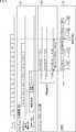
- FIG. 7is an overall sequence diagram of the first embodiment of the information processing system 11.
- three phases P1, P2, and P3 of Capability Exchange, Beam Configuration, and Multi-beam Transmissionare mainly assumed.
- FIG. 7shows information transmitted between the computer remote unit 51, the computer local unit 52, and the HMD 21 in each of the phases P1, P2, and P3.
- the HMD 21 and the computer local unit 52exchange information on whether or not Beam Configuration of Phase P2 and Multi-beam Transmission of Phase P3 can be executed.
- the computer local unit 52notifies the computer remote unit 51 of information on whether or not the HDM 21 can execute Beam Configuration in phase P2 and Multi-beam Transmission in phase P3.
- Capability Exchange in Phase P1may be executed only once when the wireless connection between the computer 22 and the HMD 21 is started.
- the transmission beam (and the transmission beam) used by the computer remote unit 51 to transmit the coded information among the plurality of beams radiable from the computer local unit 52 (image transmission communication unit 41, see FIG. 3).Determine the number of beams). That is, the computer remote unit 51 determines the transmission beam (number of beams) to be used in the multi-beam transmission of the phase P3.
- the transmission beam(transmission beam that can be used in the multi-beam transmission of the phase P3) that can be radiated from the computer local unit 52 (communication unit 41 for image transmission, see FIG. 3) is used in the HMD 21.
- the HMD 21notifies the computer remote unit 51 of the arrival direction AoA via the computer local unit 52.
- the information regarding the setting of the antenna reception sensitivity (directivity of the reception beam) in the HMD 21is transmitted from the computer remote unit 51 to the computer local unit 52. Notify the HMD 21 via.
- the computer remote unit 51sends a Setup Request to the computer local unit 52 to start the Beam Configuration of the phase P2, but this is the start of the Beam Configuration of the phase P2. Not limited to.
- the Setup Requestmay be transmitted to the computer remote unit 51 and the HMD 21 by the request from the computer local unit 52, and the Setup Request may be transmitted to the computer local unit 52 and the computer remote unit 51 by the request from the HMD 21. May be good.
- Beam Configuration of Phase P2does not necessarily have to be executed before the Multi-beam Transmission of Phase P3 as shown in FIG.
- the computer remote unit 51transmits a plurality of coded information corresponding to a plurality of future states of the HMD 21 predicted by the computer remote unit 51 to the computer local unit 52.
- the computer local unit 52transmits each coding information to the HMD 21 by a plurality of different transmission beams. Further, the HMD 21 transmits the reception result of the coded information in the HMD 21 to the computer remote unit 51 via the computer local unit 52.
- Capability Exchange in Phase P1In the Capability Exchange of Phase P1, in step S1, the computer remote unit 51 transmits a Capability Request to the computer local unit 52.
- the Capability Requestincludes information requesting the exchange of Capability information between the computer remote unit 51 and the HMD 21 connected to the computer local unit 52.
- step S2the computer local unit 52 that has received the Capability Request transmits Capability information to the HMD 21.
- step S3the HMD 21 that has received the Capability information transmits the Capability information to the computer local unit 52.
- step S4the computer local unit 52 that has received the Capability information transmits a Capability Report to the computer remote unit 51.
- the Capability Reportincludes information indicating the Capability information of the HMD 21 received by the computer local unit 52.
- steps S1 and S2may be performed after steps S3 and S4.
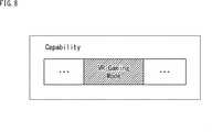
- FIG. 8is a diagram showing an example of a frame configuration for storing Capability information.
- the frame for transmitting the Capability informationincludes VR Gaming Mode information
- the VR Gaming Mode informationincludes Beam in which the communication terminals (computer local unit 52 and HMD 21) for transmitting the Capability information are in phase P2. It contains information indicating whether the Configuration and the Multi-beam Transmission of Phase P3 can be executed. For example, “1" may be indicated when it is feasible, and "0" may be indicated when it is not feasible, and the expression method is not limited to this.
- the computer local unit 52can determine that the transmission is completed even when the reception response to only one transmission beam from the HMD 21 is received after transmitting the plurality of transmission beams to the HMD 21, the phase P2
- the Capability information that the Beam Configuration of the above and the Multi-beam Transmission of the phase P3 can be executedis transmitted to the HMD 21.
- the HMD 21can form a receive beam having a high directivity in a specific direction such as the front direction of the HMD 21 (in a transmission / reception antenna, a receive beam having a high directivity gain in a specific direction of the HMD 21 can be generated).
- a part of the transmitted beams with high gain (received power)can be demodulated when a plurality of transmitted beams are received, Beam Configuration in phase P2 and Multi-beam Transmission in phase P3 can be executed.
- the Capability informationis transmitted to the computer local unit 52.
- step S5the computer remote unit 51 transmits a setup request to the computer local unit 52.
- the Setup Requestincludes a request for executing Beam Search to the computer local unit 52, or information indicating execution.
- the computer remote unit 51transmits the Setup Request to the computer local unit 52, but the HMD 21 may transmit the Beam Search to the computer local unit 52.
- step S6the computer local unit 52 sends a Setup Request to the HMD 21.
- step S7the computer local unit 52 transmits Beam Search to the HMD 21.
- the Beam Searchincludes information for estimating AoA in the HMD 21 with respect to the transmission beam from the computer local unit 52 (the image transmission communication unit 41 of the wireless communication unit 31).
- the transmission beam emitted by the computer local unit 52is time-division-switched while the computer 22 (what is regarded as the computer 22) and the HMD 21 are facing each other or the HMD 21 is rotating / moving. It may be transmitted to HMD 21. For example, information including a beam-specific number may be transmitted to the Beam Search for each transmitted beam to be formed.
- step S8the HMD 21 transmits an AoA Info frame to the computer local unit 52.
- the AoAInfo framecontains information indicating the arrival direction AoA in the HMD21 and the received signal quality detected by the HMD21 for each transmission beam from the computer local unit 52 received by the HMD21 in BeamSearch in step S7. ..
- FIG. 9is a diagram showing a configuration example of an AoA Info frame.
- the AoAInfo framecontains FrameControl information.
- the Frame Control informationincludes information indicating that it is an AoA Request.
- the AoAInfo frameincludes RA information
- the RA informationincludes information indicating the computer local unit 52 (the image transmission communication unit 41 of the wireless communication unit 31) which is the destination of the AoAInfo frame.
- the RA informationmay store a MAC (Media Access Control) address, but the RA information is not limited to this.
- the AoAInfo frameincludes AoA information
- the AoA informationincludes AoA of each transmission beam received by the HMD 21 in Beam Search in step S7, and information indicating the quality of the received signal.
- the AoA informationincludes AoA for each beam # 1, # 2, ..., #N, and information indicating the quality of the received signal.
- the AoA informationmay be divided into a plurality of AoA Info frames and transmitted to the computer local unit 52, and the AoA information includes information indicating whether or not the AoA information is divided into a plurality of AoA Info frames. May be good.
- step S9 of FIG. 7the computer local unit 52 transmits the AoA Report to the computer remote unit 51.
- the AoA Reportcontains AoA information.
- the computer remote unit 51(control unit 61, see FIG. 3) that received the AoA Report is computer-local based on the inertial information (not shown) simultaneously transmitted from the HMD 21 to the computer remote unit 51 via the computer local unit 52.
- Information corresponding to the transmission beam radiable from the unit 52 (the image transmission communication unit 41 of the wireless communication unit 31) and the AoA in the HMD 21 of each transmission beamis generated and stored.
- step S10 of FIG. 7the computer remote unit 51 transmits a Setting Report to the computer local unit 52 based on the AoA Report.
- step S11the computer local unit 52 that has received the Setting Report transmits the Setting Report to the HMD 21.
- the Setting Reportsets the directivity of the received beam (directivity of the received beam in the transmitting / receiving antenna) that should be set by the HMD 21 (the communication unit 91 for image transmission of the wireless communication unit 81, see FIG. 4) in the multi-beam transmission of phase P3.
- the directivity of the received beamincludes, for example, any of a plurality of transmitted beams for transmitting coding information from the computer local unit 52 in the half-value width range, and the plurality of transmitted beams are simultaneously included in the half-value width range.
- the directivitymay be set so as not to be included in.
- FIG. 10is a flowchart illustrating a processing example of the Beam Configuration of the phase P2 performed by the computer 22 when the computer 22 starts the Beam Configuration of the phase P2 (when the computer 22 sends a Setup Request to the HMD 21).
- step S41it is determined whether or not the computer 22 performs Beam Configuration of phase P2.
- the computer 22determines that the Beam Configuration of the phase P2 is performed, when the amount of change in the arrival direction of an arbitrary transmission beam in the HMD 21 exceeds a predetermined threshold value, or when the computer 22 determines that the computer local unit 52 and the HMD 21 are performed. This applies when it is determined that the propagation environment of the beam between and is changed, but the present invention is not limited to these.
- step S41If it is determined in step S41 that Beam Configuration of phase P2 is not performed, the process skips steps S41 to S44 and ends the process of this flowchart.
- step S41If it is determined in step S41 that Beam Configuration of phase P2 is to be performed, the process proceeds from step S41 to step S42.
- step S42the computer 22 sends a Setup Request to the HMD 21 to notify that the Beam Configuration of the phase P2 is executed.
- the processproceeds from step S42 to step S43.
- step S43the computer 22 executes the Beam Configuration process of phase P2. That is, the computer 22 transmits BeamSearch to the HMD21 and receives the AoAInfo frame of FIG. 9 from the HMD21. The computer 22 acquires the AoA and the received signal quality in the HMD 21 of each transmission beam radiated from the computer local unit 52 by the AoA Info frame. The process proceeds from step S43 to step S44.
- step S44the computer 22 uses the transmission beam (and the number of beams) to be used for the multi-beam transmission in phase P3 among the transmission beams radiable from the computer 22 based on the AoA of each transmission beam acquired in step S43. To determine.
- the transmission beam used for the multi-beam transmission in phase P3is called an effective beam.
- the computer 22determines as an effective beam a transmission beam such that the AoA in the HMD 21 is equal to or greater than a certain angular interval.
- the computer 22determines as an effective beam a transmission beam in which the AoA in the HMD 21 is at least a certain angle r1 interval and at least a certain angle r2 interval (r1 ⁇ r2).
- the computer 22predicts a plurality of future states of the HMD 21 from the inertial information of the HMD 21 acquired in the past, and in each of the predicted states of the HMD 21 from a direction close to the direction in which the received beam of the HMD 21 is directed.
- the incoming transmission beammay be determined as the effective beam.
- the determination direction of the effective beamis not limited to these. The process ends after step S44.
- a part of the processing of steps S41 to S44may be executed by the computer local unit 52, and the rest may be executed by the computer remote unit 51.
- the computer remote unit 51may determine whether or not the computer 22 performs Beam Configuration in phase P2, and the computer local unit 52 may execute the other steps S42 to S44.
- thisis not limited.
- steps S41 to S44do not necessarily have to be executed.
- the determination of the effective beam (and the number of beams) used for the multi-beam transmission in phase P3is executed in Beam Configuration in phase P2. It does not have to be done.
- FIG. 11is a flowchart illustrating a process of determining an effective beam (and the number of beams) used for the multi-beam transmission in phase P3 in step S44 of FIG.
- step S51the computer 22 receives the AoA Report from the HMD 21. The process proceeds from step S51 to step S52.
- step S52the computer 22 can transmit from the computer 22 (the image transmission communication unit 41 of the wireless communication unit 31) based on the inertia information transmitted from the HMD 21 in the past and the AoA Report received in step S51.
- the transmission beam that satisfies the required QoS (Quality of Service) and the number of beamsare obtained. The process proceeds from step S52 to step S53.
- a satisfactory Motion to Photon Latencyis defined, and in any combination b of a transmission beam radiable from the computer 22 (a transmission beam that can be used in Multi-beam Transmission in phase P3), the i-th Inertia information of HMD21 when AoA in HMD21 is ⁇ (b (i)) and ⁇ (b (j)) for beam b (i) and j-beam b (j) (i ⁇ j), respectively.
- ⁇ c (degrees)obtained by, a beam combination b0 and a beam number Nb that satisfy the following equation (1) may be obtained.
- a beam combination b'which is a transmission beam combination b0 having the minimum number of elements, is obtained. Further, the number of beams Nb of the combination b0 of the transmission beams is obtained.
- the norms for determining the transmission beam and the number of beamsneed not be limited to the above.
- step S53when the computer 22 transmits a number of video information (encoding information) corresponding to the number of beams Nb from the computer remote unit 51 to the computer local unit 52 by Image Transmission, the computer remote unit 51 and the computer local unit 52 Determine if the communication capacity of is sufficient.
- step S53If it is determined in step S53 that the communication capacities of the computer remote unit 51 and the computer local unit 52 are sufficient, the process proceeds to step S54, and the computer remote unit 51 transmits video information to the computer local unit 52 by Image Transmission. Determine the number to Nb.
- step S54the process of this flowchart is completed.
- step S53when it is determined that the communication capacities of the computer remote unit 51 and the computer local unit 52 are insufficient, that is, the amount of video information corresponding to the number of beams Nb is transmitted from the computer remote unit 51 to the computer local by Image Transmission.
- the required communication rate C0 (bps) for transmitting to the unit 52is larger than the communication rate C (bps) between the computer remote unit 51 and the computer local unit 52, the process proceeds to step S55.
- step S55the computer 22 reduces the amount of information transmitted from the computer remote unit 51 to the computer local unit 52 by Image Transmission to an amount of information such that the communication rate is C0 or less.
- the amount of informationmay be reduced by lowering the compression rate at the time of encoding of the encoder unit 32 (see FIG. 3), or by reducing the number of beams Nb and using Image Transmission from the computer remote unit 51 to the computer local unit 52. This may be done by reducing the number of video information (encoding information) transmitted to the computer.
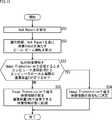
- FIG. 12is a flowchart illustrating a processing example of the HMD 21 when the computer 22 starts the Beam Configuration of the phase P2 (when the computer 22 sends a Setup Request to the HMD 21).
- step S61the HMD 21 determines whether or not the Setup Request from the computer 22 has been notified.
- step S61If it is determined in step S61 that the Setup Request has not been notified, the process skips step S62 and ends the process of this flowchart.
- step S61If it is determined in step S61 that the Setup Request has been notified, the process proceeds to step S62, and the HMD 21 executes the Beam Configuration process of phase P2. When the process of step S62 is completed, the process of this flowchart is completed.
- the HMD 21when the HMD 21 starts the Beam Configuration process of the phase P2, after receiving the Beam Search from the computer 22, the HMD 21 receives the AoA of each transmission beam and the information indicating the quality of the received signal (AoA information, see FIG. 9). It is stored in the AoAInfo frame and transmitted to the computer 22. At this time, if the number of beams for which AoA is detected by the HMD 21 is large, the HMD 21 may divide the AoA information of all the transmission beams into a plurality of AoA Info frames and transmit the AoA information to the computer 22. Further, a plurality of AoA Info frames may include AoA information of the same transmission beam.
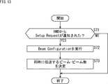
- FIG. 13is a flowchart illustrating a processing example of the Beam Configuration of the phase P2 performed by the computer 22 when the HMD 21 starts the Beam Configuration of the phase P2 (when the HMD 21 sends a Setup Request to the computer 22).
- step S71the computer 22 determines whether or not the Setup Request has been notified from the HMD 21.
- step S71If it is determined in step S71 that the Setup Request has not been notified from the HMD 21, the process skips steps S72 and S73 and ends the process of this flowchart.
- step S71If it is determined in step S71 that the Setup Request has been notified from the HMD 21, the process proceeds from step S71 to step S72.
- step S72the computer 22 executes Beam Configuration of phase P2. That is, the computer 22 transmits BeamSearch to the HMD21 and receives the AoAInfo frame from the HMD21. Then, the computer 22 acquires the AoA in the HMD 21 of each transmission beam from the computer local unit 52 and the received signal quality information by the received AoA Info frame. The process proceeds from step S72 to step S73.
- step S73the computer 22 is used to transmit the converted video information (encoded information) in the AoA in the HMD 21 of each transmission beam acquired in step S72 and the Multi-beam Transmission in the phase P3 based on the received signal quality. Determine the effective beam (and number of beams) to be (transmitted at the same time).
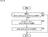
- FIG. 14is a flowchart illustrating a processing example of the HMD 21 when the HMD 21 starts the Beam Configuration of the phase P2 (when the HMD 21 sends a Setup Request to the computer 22).
- step S81the HMD 21 determines whether or not to perform Beam Configuration in phase P2.
- the amount of change in AoA in the HMD 21 with respect to an arbitrary transmission beam from the computer 22may exceed a predetermined threshold value.
- the HMD 21determines that the Beam Configuration of the phase P2 is performed, there is a case where the HMD 21 determines that the propagation environment between the computer local unit 52 and the HMD 21 has changed.
- the movement amount of the HMD 21may exceed a predetermined threshold value based on the inertial information acquired by the HMD 21. However, this is not the case when it is determined that the HMD 21 performs the Beam Configuration of the phase P2.
- step S81If it is determined in step S81 that Beam Configuration of phase P2 is not performed, the process skips steps S82 and S83 and ends the process of this flowchart.
- step S81If it is determined in step S81 that Beam Configuration of phase P2 is to be performed, the process proceeds from step S81 to step S82.
- step S82the HMD 21 notifies the computer 22 of the Setup Request and requests that the Beam Configuration of the phase P2 be executed. The process proceeds from step S82 to step S83.
- step S83the HMD 21 executes Beam Configuration. That is, after receiving Beam Search from the computer local unit 52, the HMD 21 stores the AoA of each transmission beam and the received signal quality information (AoA information, see FIG. 9) in the AoA Info frame and transmits the information to the computer 22. To do.
- the process of step S83is completed, the process of this flowchart is completed.
- the computer 22has video information (encoded information) in the Multi-Beam Transmission of phase P3 of FIG. 7 based on the inertia information of the HMD 21 and the information of the tracker 35 (see FIG. 3) transmitted from the HMD 21 to the computer 22 in the past. Predict the future state of the HMD 21 at the time of reception.
- the state of the HMD 21may be the direction in which the HMD 21 faces (front direction) or the position of the HMD 21 (three-dimensional coordinates), but is not limited thereto.
- a plurality of statesare predicted as future states of the HMD 21, one state may be used.
- the original video information generated by rendering on the computer 22(video generation unit 34) is converted into video information according to the future state of the HMD 21.
- the converted video informationis encoded by the encoder unit 32 (see FIG. 3), converted into encoded information, and then assigned to the encoded information by the wireless communication unit 31 (see FIG. 3) (effective beam). ) Is transmitted to the HMD 21.
- a transmission beam whose AoA is the direction closest to the direction in which the reception beam formed by the HMD 21 is directed in the future state of the HMD 21is assigned as a transmission beam for transmitting the coded information generated according to the future state. Be done.
- FIG. 7shows a case where n future states of the HMD 21 are predicted and the coded information is transmitted from the computer local unit 52 to the HMD 21 as Image Data by a total of n transmission beams.
- step S12 of FIG. 7the converted video information converted from the original video information by the video generation unit 34 of the computer remote unit 51 of FIG. 3 is encoded into the coded information by the encoder unit 32, and then from the computer remote unit 51. It is transmitted as an Image Transmission to the computer local unit 52 via the core communication unit 62 and the core communication unit 72.
- step S13the wireless communication unit 31 (see FIG. 3) of the computer local unit 52 transmits the received Image Transmission (encoding information) to the HMD 21 as Image Data by the assigned transmission beam.
- one coded informationmay be divided into a plurality of pieces by the wireless communication unit 31 and transmitted to the HMD 21 as a plurality of Image Data. Further, a plurality of Image Data may be continuously transmitted to the HMD 21 in one Multi-Beam Transmission.
- step S14the computer local unit 52 transmits an Ack Request to the HMD 21.
- the AckRequestcontains information indicated to request a receive response to the previously transmitted ImageData.
- step S15the HMD 21 transmits an Ack frame to the computer local unit 52.
- FIG. 15is a diagram showing a configuration example of an Ack frame.
- the Ack framecontains information indicating whether the Image Data was correctly received by the HMD 21 without any error.
- the Frame Control information and RA informationare the same as the AoA Info of FIG. 9, and the Frame Control information includes information indicating that this frame is an Ack frame.
- the RA informationincludes information indicating the destination wireless communication terminal (wireless communication unit 31 of the computer local unit 52) to be received.
- the information indicating the wireless communication terminalmay be a MAC address, but is not limited to this.
- AckInfo informationincludes Bitmap and AoA as information related to multiple ImageData received immediately before the Ack frame.
- Bitmapstores information indicating whether Image Data was received correctly. For example, when Image Data is received in N frames immediately before, Bitmap # 1 to # N include information indicating that each frame has been received correctly without error. Bitmap # 1 to #N may store "1" when each frame is correctly received, and "0" when each frame is not received correctly, but the present invention is not limited to this.
- AoAincludes information indicating AoA of the beam of Image Data received by HMD21 immediately before. For example, when Image Data is received for N frames immediately before, information indicating AoA of the transmission beam for K frames in the image data may be included in AoA # 1 to # K.
- step S16 of FIG. 7the computer local unit 52 that has received the Ack frame transmits the Ack Report to the computer remote unit 51.
- FIG. 16is a flowchart illustrating a processing example performed by the computer 22 in the Multi-Beam Transmission of the phase P3.
- step S91the computer 22 determines whether or not the HMD 21 supports Multi-Beam Transmission in phase P3 based on the VR Gaming Mode information among the Capability information exchanged in advance.
- step S91If it is determined in step S91 that the HMD 21 does not support Multi-Beam Transmission in phase P3, the process proceeds to step S92, and the computer 22 selects a beam having high communication quality and transmits Image Data to the HMD 21. Then, the processing of this flowchart is completed.
- step S91If it is determined in step S91 that the HMD 21 corresponds to the Multi-Beam Transmission of the phase P3, the process proceeds from step S91 to step S93, and the computer 22 starts the Multi-Beam Transmission.
- step S93the computer 22 selects a transmission beam (effective beam) to be used in the Multi-Beam Transmission. The process proceeds from step S93 to step S94.
- step S94the computer 22 applies video conversion corresponding to each of the plurality of selected transmission beams to the original video information to generate Image Deta (encoding information). The process proceeds from step S94 to step S95.
- step S95the computer 22 transmits Image Deta to the HMD 21 by the selected transmission beam.
- step S95the process of this flowchart is completed.
- each process of steps S91 to S95may be executed by either the computer remote unit 51 or the computer local unit 52, and all the processes are executed by either the computer remote unit 51 or the computer local unit 52. No need.
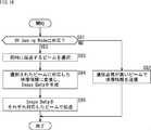
- FIG. 17is a flowchart illustrating a processing example performed by the HMD 21 in the Multi-Beam Transmission of the phase P3.
- step S101the HMD 21 determines whether or not the computer 22 supports Multi-Beam Transmission based on the VR Gaming Mode information among the Capability information exchanged in advance.
- step S101If it is determined in step S101 that the computer 22 does not support Multi-Beam Transmission, the process proceeds from step S101 to step S102.
- step S102the HMD 21 selects a beam having high communication quality, receives and demodulates Image Data from the computer 22, and the process proceeds to step S105.
- step S101If it is determined in step S101 that the computer 22 supports Multi-Beam Transmission, the process proceeds from step S101 to step S103.
- step S103the HMD 21 sets the directivity of the antenna that receives the transmission beam from the computer 22 to a state determined in advance between the computer 22 and the HMD 21.
- the directivity of the received beam of the HMD 21may be determined based on the information included in the Setting Report and the Capability information in the Beam Configuration of Phase P2.
- the HMD 21receives Image Data from the computer 22. Further, the HMD 21 receives the Image Data transmitted by the transmission beam selected according to the predetermined selection norm. For example, the HMD 21 may select and receive only the transmission beam having the highest received power (reception gain) among the plurality of transmitted beams that have arrived, but the selection norm is not limited to this.
- the directivity of the received beam of the HMD 21may be changed according to the inertial information obtained in the HMD 21. For example, the half width of the received beam may be changed. The process proceeds from step S104 to step S105.
- step S105the HMD 21 performs decoding processing and drawing processing on the received Image Data to generate video information and display it on the display 86.
- the process of this flowchartis completed.
- Embodiment 2>> ⁇ Outline of the process of the second embodiment>
- the second embodiment of the information processing system 11 composed of the computer 22 of the first configuration example of FIG. 2will be described.
- FIG. 18is a diagram showing an outline of the process of the second embodiment of the information processing system 11.
- the time axis(horizontal axis) is divided by time slots at regular time intervals, and the times t0, t1, t2, ... Are represented in time slot units, as in FIG. FIG. 18 shows the timing of various processes performed on the computer 22 and the HMD 21 corresponding to the time axis.
- the computer 22is relatively close to the HMD 21, such as in the same building, and directly communicates wirelessly with the HMD 21.
- the image generation unit 34renders the numerical data in, for example, three-dimensional graphics given by the control unit 33 (see FIG. 2) in the period from time t0 to time t2. And generate the original video information to be displayed on the HMD 21. Then, the video generation unit 34 converts the generated original video information into converted video information according to the future state of the HMD 21 at the future time t5.
- the control unit 33is based on the inertia information ⁇ (t) (t is the time before t1) from the HMD 21 to the latest (latest) already acquired from the HMD 21 at the time t2 when the image generation unit 34 generates the original video information.
- a plurality of future states of the HMD 21 at time t5are predicted, and a plurality of states having different front directions of the HMD 21 are predicted, and a plurality of predicted future states of the HMD 21 are supplied to the image generation unit 34. Since the inertia information ⁇ (t) is the same as that in FIG. 5, the description thereof will be omitted.
- the video generation unit 34generates converted video information according to each of the plurality of future states of the HMD 21 at time t5 by video conversion of the original video information.
- the encoder unit 32independently encodes the converted video information corresponding to a plurality of future states of the HMD 21 generated by the video generation unit 34 into encoded information and transmits the converted video information to the wireless communication unit 31.
- the wireless communication unit 31(image transmission communication unit 41) generates a plurality of beams # 1 to #N (N is 2 or more) having directivity, and each of the beams # 1 to #N causes the encoder unit 32 to generate a plurality of beams # 1 to # N.
- Each of the plurality of coded video information of the aboveis transmitted to the HMD 21. Since the beams # 1 to #N are the same as those in FIG. 5, the description thereof will be omitted.
- the control unit 33allocates a transmission beam that transmits each of a plurality of coded information from the transmission beams that can be radiated from the wireless communication unit 31. For example, when the control unit 33 assumes each state of a plurality of future states of the predicted HMD 21, the control unit 33 arrives from the direction closest to the direction in which the received beam formed by the HMD 21 in the assumed state is directed.
- the directional transmit beamis assigned as the transmit beam that transmits the coded information generated corresponding to the assumed state.
- control unit 33supplies the wireless communication unit 31 with beam allocation information indicating the allocation of the transmission beam for each coding information.
- the wireless communication unit 31transmits each of the plurality of coded information from the encoder unit 32 from the image transmission communication unit 41 to the HMD 21 by a transmission beam according to the beam allocation information from the control unit 33.
- the HMD 21forms a reception beam in the image transmission communication unit 91 (see FIG. 4) of the wireless communication unit 81 so as to increase the reception sensitivity of the beam in a specific direction and have directivity.
- the image transmission communication unit 91forms, for example, a directional reception beam that maximizes the reception power with respect to the direction in which the reception beam formed by the HMD 21 is directed.
- the image transmission communication unit 91faces the reception beam of the HMD 21 among the transmission beams of the plurality of beams # 1 to # N radiated from the wireless communication unit 31 (image transmission communication unit 41) of the computer 22 (reception beam). Only the coded information transmitted by the transmission beam in the arrival direction coming from the direction closest to (the direction in which the reception power is maximum) is received.
- the coded information corresponding to the state closest to the actual state of the HMD 21 at the time t5is the received beam of the HMD 21. It is transmitted to the HMD 21 by a transmission beam arriving from the direction closest to the direction of the head.
- the wireless communication unit 81 of the HMD 21demodulates only the transmission beam having the highest received power among the transmission beams arriving at the image transmission communication unit 91, and receives the coded information transmitted by the beam.
- the wireless communication unit 81uses the coding information # 1-a and # 2- of the beams # 1 to #N radiated from the wireless communication unit 31 of the computer 22 at time t5, which are transmitted by the beam #a. Indicates that a has been received for two consecutive frames. Further, the wireless communication unit 81 continues to receive the coded information until the time t7. Since the state of the HMD 21 changes during the period from the time t5 to the time t7, the wireless communication unit 81 has the coding information # km transmitted by the beam #m different from the beam #a by the time t7. Is illustrated.
- the coded information received by the wireless communication unit 31is subjected to drawing processing such as decoding processing in the video generation unit 84 of FIG. 4, and the converted video information before being encoded by the encoder unit 32 of the computer 22 is stored. It is temporarily stored in the unit 85. Then, the video information stored in the storage unit 85 is displayed on the display 86 from the time t8 when the drawing process of the coded information received in the period from the time t5 to the time t7 is completed.
- Motion to Photon Latencyis the delay time related to the display. Is mainly the sum of the transmission delay and the drawing delay.
- the HMD 21receives the video information according to the state of the HMD 21 itself, it is not necessary to correct the video information with the HMD 21, and the processing capacity of the HMD 21 can be reduced. Therefore, the size, weight, and cost of the HMD 21 can be reduced.
- the HMD 21receives the video information (encoding information) of the transmission beam arriving from the direction closest to the direction in which the reception beam is basically directed, among the plurality of transmission beams simultaneously transmitted from the computer 22. Since the video information according to the state of the HMD 21 can be obtained, it is not necessary to select the beam, and the processing load does not increase.
- FIG. 19is an overall sequence diagram of the second embodiment of the information processing system 11.
- the information exchanged between the computer 22 and the HMD 21is also included. It is the same as the information exchanged between the computer local unit 52 and the HMD 21 in the first embodiment.
- steps S111 and S112 in the Capability Exchange of Phase P1 of FIG. 19correspond to Steps S2 and S3 of the Capability Exchange of Phase P1 of FIG. 7.
- Steps 113 to S116 in Beam Configuration of Phase P2 of FIG. 19correspond to Steps S6 to S8 and Step S11 of Beam Configuration of Phase P2 of FIG. 7.
- Steps S117 to S119 in the Multi-beam Transmission of Phase P3 of FIG. 19correspond to Steps S13 to S15 of the Multi-beam Transmission of Phase P3 of FIG. 7.
- the Setup Requestis executed from the computer 22 side in the Beam Configuration of the phase P2, but the Setup Request may be executed from the HMD 21 as in the first embodiment.
- FIG. 20is a flowchart illustrating a process of determining a beam to be used for simultaneous transmission of coded information in Image Transmission of Phase P3 of the second embodiment.
- the limitlimits the number of converted video information (encoded information) that can be generated. For example, if the converted video information can be generated only up to N0 due to the calculation performance limit of the computer 22, the upper limit of the number of converted video information that can be generated with N0 as a fixed threshold value may be set to N0. However, the threshold value is not limited to this.
- step S121the computer 22 receives the AoA Report (AoA info) from the HMD 21. The process proceeds from step S121 to step S122.
- step S122the computer 22 obtains a transmission beam that satisfies the required QoS (Quality of Service) based on the inertia information of the HMD 21 fed back in the past and the AoA Report.
- QoSQuality of Service
- step S123the computer 22 determines whether or not a number of video information corresponding to the number of beams Nb of the transmission beam satisfying the QoS can be transmitted to the HMD 21 by Image Transmission based on the calculation performance of the computer 22.
- step S123If it is determined in step S123 that the number of video information corresponding to the number of beams Nb can be transmitted to the HMD 21 by Image Transmission, the process proceeds to step S124, and the computer 22 sets the number of video information transmitted by Image Transmission to Nb. decide. When the process of step S123 is completed, the process of this flowchart is completed.
- step S123if it is determined in step S123 that the number of video information corresponding to the number of beams Nb cannot be transmitted to the HMD 21 by Image Transmission, the process proceeds to step S125, and the computer 22 proceeds to the number of video information transmitted by Image Transmission. Is reduced to a number less than Nb. That is, since all the video information cannot be transmitted to the HMD 21 by the transmission beam, the computer 22 reduces the number of video information transmitted by the image transmission to the number that can be generated by the computing performance of the computer 22.
- step S125the process of this flowchart is completed.
- the HMD 21since the HMD 21 receives the video information according to the state, it is not necessary to perform processing such as video correction in the HMD 21, so that the processing capacity of the HMD 21 can be reduced. Therefore, the size, weight, and cost of the HMD 21 can be reduced.
- the HMD 21is basically a video information (encoding information) of a transmission beam arriving from the direction closest to the direction in which the reception beam formed by the HMD 21 is directed among a plurality of transmission beams simultaneously transmitted from the computer 22. Is received, video information according to the state of the HMD 21 can be obtained, so that it is not necessary to select a beam and the processing load does not increase.
- the optimum transmission path that follows the state change of the HMD 21can be secured by appropriately changing the transmission beam for transmitting video information, and the signal quality can be improved. Can be improved.
- ⁇ Program> Part or all of the processing of the computer 22 of FIG. 1, the HMD 21 of FIG. 1, the computer remote unit 51 of FIG. 3, and the computer local unit 52 of FIG. 3can be executed by hardware or by software. You can also do it.
- the programs constituting the softwareare installed on the computer.
- the computerincludes a computer embedded in dedicated hardware and, for example, a general-purpose personal computer capable of executing various functions by installing various programs.
- FIG. 21is a block diagram showing a configuration example of computer hardware that executes the above-mentioned series of processes programmatically.
- a CPUCentral Processing Unit
- ROMReadOnly Memory
- RAMRandomAccessMemory
- An input / output interface 205is further connected to the bus 204.
- An input unit 206, an output unit 207, a storage unit 208, a communication unit 209, and a drive 210are connected to the input / output interface 205.
- the input unit 206includes a keyboard, a mouse, a microphone, and the like.
- the output unit 207includes a display, a speaker, and the like.
- the storage unit 208includes a hard disk, a non-volatile memory, and the like.
- the communication unit 209includes a network interface and the like.
- the drive 210drives a removable medium 211 such as a magnetic disk, an optical disk, a magneto-optical disk, or a semiconductor memory.
- the CPU 201loads the program stored in the storage unit 208 into the RAM 203 via the input / output interface 205 and the bus 204 and executes the above-described series. Is processed.
- the program executed by the computercan be recorded and provided on the removable media 211 as a package media or the like, for example.
- the programcan also be provided via a wired or wireless transmission medium such as a local area network, the Internet, or digital satellite broadcasting.
- the programcan be installed in the storage unit 208 via the input / output interface 205 by mounting the removable media 211 in the drive 210. Further, the program can be received by the communication unit 209 and installed in the storage unit 208 via a wired or wireless transmission medium. In addition, the program can be pre-installed in the ROM 202 or the storage unit 208.
- the program executed by the computermay be a program that is processed in chronological order according to the order described in this specification, or may be a program that is processed in parallel or at a necessary timing such as when a call is made. It may be a program in which processing is performed.
- the present technologycan also have the following configurations.
- a video generatorthat converts video information based on inertial information transmitted from the display device to generate a plurality of different converted video information.
- a video transmission deviceincluding a wireless communication unit that transmits a plurality of different converted video information generated by the video generation unit to the display device by beams different from each other.
- ⁇ 2>Further having an encoder unit for encoding the converted video information into coding information.
- ⁇ 3>The video according to ⁇ 1> or ⁇ 2>, wherein the video generation unit generates the converted video information according to the state of the display device that receives the video information predicted based on the inertia information. Transmitter.
- ⁇ 4>The video transmission device according to ⁇ 3>, wherein the wireless communication unit transmits the converted video information according to the state of the display device by a beam that can be received by the display device in the state.
- ⁇ 5>The video transmission device according to ⁇ 4>, further comprising a control unit that controls the wireless communication unit to transmit the converted video information by the beam.
- ⁇ 6>The video transmission device according to any one of ⁇ 1> to ⁇ 5>, wherein notification information regarding the arrival direction of a plurality of different beams transmitted from the wireless communication unit on the display device is acquired from the display device. .. ⁇ 7>
- a beam used for transmitting the converted video informationis selected from a plurality of beams that can be transmitted from the wireless communication unit ⁇ 6> or ⁇ 7>.
- ⁇ 9>The video transmission according to any one of ⁇ 1> to ⁇ 8>, wherein the number of beams used for transmitting the converted video information from the wireless communication unit is controlled based on the calculation performance of the video transmission device.
- apparatus. ⁇ 10>It has a first device unit having the video generation unit and a second device unit having the wireless communication unit.
- the first device unitis A first control unit that predicts a plurality of states in which the display device can perform a receiving operation based on the inertial information from the display device, and The converted video information generated by the video generation unit, and each of the plurality of converted video information generated according to the plurality of states predicted by the first control unit is used as encoded information.
- Encoder section to encode and The description in ⁇ 10>which further includes a first communication unit that transmits the coded information to the second device unit and receives the inertial information from the display device from the second device unit.
- Video transmitter⁇ 12>
- the second device unitis A second communication unit that receives the coded information from the first device unit and transmits the inertial information from the display device to the first device unit.
- the second control unitfurther comprises a second control unit that controls the wireless communication unit to transmit the coded information in which the converted video information is encoded by beams different from each other for each of the converted video information.
- Video transmitterAt least one of the first control unit and the second control unit is from the wireless communication unit due to the communication capacity between the first device unit and the second control unit.
- the video transmission deviceaccording to ⁇ 12>, which controls the number of beams used for transmitting the coded information.
- a wireless communication unitthat demodulates a part of a plurality of beams coming from the video transmitter, and A display that displays video information obtained by demodulating the beam by the wireless communication unit, and A position module that acquires inertial information by measurement, A display device having an inertia information communication unit that transmits the inertia information acquired by the position module to the video transmission device.
- ⁇ 16>The display according to ⁇ 14> or ⁇ 15>, which notifies the video transmission device of information regarding the arrival direction of each beam when the video information is transmitted from the video transmission device by a plurality of different beams. apparatus.
- ⁇ 17>The display device according to any one of ⁇ 14> to ⁇ 16>, wherein the wireless communication unit forms a beam in accordance with a request from the video transmitting device.
- a request to the video transmission device to perform a process for acquiring information regarding the arrival direction of the beam transmitted from the video transmission deviceis made based on the inertial information acquired by the position module.
- ⁇ 19>Described in any one of ⁇ 14> to ⁇ 18>, the ability information indicating that the display device corresponds to the video transmitting device that transmits video information by a plurality of different beams is notified to the video transmitting device.
- Display device. ⁇ 20>The display device according to any one of ⁇ 14> to ⁇ 19>, wherein the directivity of the beam formed by the wireless communication unit is controlled based on the inertial information obtained by the position module.
Landscapes
- Engineering & Computer Science (AREA)
- Signal Processing (AREA)
- Multimedia (AREA)
- Theoretical Computer Science (AREA)
- General Engineering & Computer Science (AREA)
- General Physics & Mathematics (AREA)
- Physics & Mathematics (AREA)
- Human Computer Interaction (AREA)
- Databases & Information Systems (AREA)
- Computer Networks & Wireless Communication (AREA)
- Computer Hardware Design (AREA)
- Computer Security & Cryptography (AREA)
- Computer Graphics (AREA)
- Mobile Radio Communication Systems (AREA)
Abstract
Description
Translated fromJapanese本技術は、映像送信装置、及び、表示装置に関し、特に、表示装置の状態に則した映像を映像送信装置から無線により送信する映像送信装置、及び、表示装置に関する。The present technology relates to a video transmission device and a display device, and more particularly to a video transmission device and a display device that wirelessly transmits a video according to the state of the display device from the video transmission device.
特許文献1には、HMD(Head Mounted Display)に内蔵された慣性センサを利用してHMDの移動距離が所定の閾値を超えた場合に、HMD内でリアルタイムに画像を修正する技術が開示されている。
HMD等の表示装置の軽量化や小型化のためには、表示装置に要求される処理能力を低減することが望まれる。In order to reduce the weight and size of display devices such as HMDs, it is desired to reduce the processing capacity required for display devices.
本技術は、このような状況に鑑みてなされたものであり、表示装置の状態に則した映像を映像送信装置から無線により送信できるようにし、表示装置の処理能力の低減を図るものである。This technology was made in view of such a situation, and is intended to enable wireless transmission of video according to the state of the display device from the video transmission device and reduce the processing capacity of the display device.
本技術の第1の側面の映像送信装置は、表示装置から送信された慣性情報に基づいて映像情報を変換して複数の異なる変換映像情報を生成する映像生成部と、前記映像生成部により生成された複数の異なる前記変換映像情報を互いに異なるビームにより前記表示装置に送信する無線通信部とを有する映像送信装置である。The video transmission device of the first aspect of the present technology is generated by a video generation unit that converts video information based on inertial information transmitted from the display device to generate a plurality of different converted video information, and the video generation unit. It is a video transmission device having a wireless communication unit that transmits a plurality of different converted video information to the display device by different beams.
本技術の第1の側面の映像送信装置においては、表示装置から送信された慣性情報に基づいて映像情報が変換され、複数の異なる変換映像情報が生成される。生成された複数の異なる変換映像情報が互いに異なるビームにより前記表示装置に送信される。In the video transmission device of the first aspect of the present technology, the video information is converted based on the inertial information transmitted from the display device, and a plurality of different converted video information is generated. A plurality of different converted video information generated is transmitted to the display device by beams different from each other.
本技術の第2の側面の表示装置は、映像送信装置から到来する複数のビームのうちの一部を復調する無線通信部と、前記無線通信部により前記ビームを復調して得られた映像情報を表示するディスプレイと、計測により慣性情報を取得する位置モジュールと、前記位置モジュールにより取得された前記慣性情報を前記映像送信装置に送信する慣性情報通信部とを有する表示装置である。The display device on the second aspect of the present technology includes a wireless communication unit that demodulates a part of a plurality of beams arriving from the video transmission device, and video information obtained by demodulating the beam by the wireless communication unit. It is a display device having a display for displaying the above, a position module for acquiring inertial information by measurement, and an inertial information communication unit for transmitting the inertial information acquired by the position module to the video transmission device.
本技術の第2の側面の表示装置においては、映像送信装置から到来する複数のビームのうちの一部が復調され、復調して得られた映像情報が表示される。計測により慣性情報が取得され、取得された前記慣性情報が映像送信装置に送信される。In the display device on the second aspect of the present technology, a part of a plurality of beams arriving from the video transmitting device is demodulated, and the video information obtained by demodulation is displayed. Inertia information is acquired by measurement, and the acquired inertia information is transmitted to the video transmission device.
以下、図面を参照しながら本技術の実施の形態について説明する。Hereinafter, embodiments of the present technology will be described with reference to the drawings.
<<システム構成>>
図1は、本技術を適用した情報処理システムの一実施の形態の構成例を示したブロック図である。<< System configuration >>
FIG. 1 is a block diagram showing a configuration example of an embodiment of an information processing system to which the present technology is applied.
図1において、情報処理システム11は、HMD(Head Mounted Display)21とコンピュータ22とを有する。In FIG. 1, the
HMD21は頭部周囲に装着する携帯デバイスであり、両眼から近い位置にあるディスプレイがユーザの状態に合わせた映像を表示する。The HMD21 is a portable device worn around the head, and a display located close to both eyes displays an image according to the user's condition.
コンピュータ22は、HMD21で表示する映像情報(画像情報)の生成とHMD21への映像情報の転送を行う。HMD21は無線伝送によって、コンピュータ22と接続される。The
HMD21からは慣性情報を含めた制御情報が無線伝送され、コンピュータ22はHMD21から送られた制御情報に基づきHMD21に表示する映像を生成する。映像情報及び制御情報における無線通信方式の相違は問わないが、例えば、高い伝送レートが要求される映像情報の無線伝送には、60GHz帯を利用した無線規格等の通信方式が用いられ、低い伝送レートでも十分であるような制御情報の無線伝送には、Bluetooth(登録商標)等の無線規格の通信方式が用いられる。Control information including inertial information is wirelessly transmitted from the HMD 21, and the
尚、コンピュータ22は任意の汎用または専用コンピュータであってよく、たとえばゲームコンソール、パーソナルコンピュータ、携帯デバイスなどでもよいが、これらに限定されない。また、コンピュータ22の一部、例えば、HMD21と無線通信を行う部分以外は、インターネット等のネットワークを通じて接続されるサーバやデータセンタのコンピュータ等のようにHMD21から離れた遠隔地に置かれていてもよい。また、コンピュータ22の一部は、ネットワークを通じて提供されるコンピューティングサービス(クラウドサービス等)により構築されてもよい。The
<<コンピュータの構成>>
<第1構成例>
図2は、図1のコンピュータ22の第1構成例を示したブロック図である。コンピュータ22は、無線通信部31、エンコーダ部32、制御部33、映像生成部34、及び、トラッカ35を有する。<< Computer configuration >>
<First configuration example>
FIG. 2 is a block diagram showing a first configuration example of the
無線通信部31は、HMD21と無線通信を行う。無線通信部31は、画像伝送用通信部41と慣性計測用通信部42とを有する。The
画像伝送用通信部41は、1つ又は2つ以上のビーム(マルチビーム)を用いてHMD21と無線通信を行う。ビームは電波の指向性を示し、フェーズシフタやデジタル演算により動的に形成される。また、画像伝送用通信部41は、放射方向が異なる複数のビームを生成することができ、かつ、ビームごとに異なる映像情報を送信させることができる。The image
画像伝送用通信部41からHMD21には、例えば、HMD21に表示させる映像情報(画像情報)が送信される。また、画像伝送用通信部41からHMD21、又は、HMD21から画像伝送用通信部41には、例えば、画像伝送用通信部41のビームの設定等に必要な制御情報が送信されてもよい。For example, video information (image information) to be displayed on the HMD 21 is transmitted from the image
慣性計測用通信部42は、HMD21に具備されている複数の慣性センサにより得られた慣性情報を無線通信によりHMD21(後述の慣性計測用通信部92)から取得する。The inertial
エンコーダ部32は、映像生成部34により生成された映像情報を符号化する。The
制御部33は、コンピュータ22の全体を統括的に制御する。また、制御部33は、映像情報の生成に必要な情報を映像生成部34に供給する。また、制御部33は、エンコーダ部32により符号化された映像情報を無線通信部31の画像伝送用通信部41からHMD21に送信する際に、画像伝送用通信部41が生成できる複数のビームのうちのどのビームで映像情報を送信させるか等を決定する。The
映像生成部34は、制御部33から供給された情報に基づいて、HMD21において表示する映像情報の生成(レンダリング)を行い、生成した映像情報を直近の慣性情報に基づいて変換・修正する。そして、映像生成部34は変換した映像情報をエンコーダ部32に供給する。The
トラッカ35は、HMD21の位置を把握するために用いられ、たとえばカメラやLiDAR(Light Detection and Ranging)、レーダーなどで実現されてもよいが、これらに限定されず、また、必ずしも必要とされる要素ではない。The
ここで、映像生成部34は、例えば3次元グラフィックスにおける数値データとして制御部33または他に映像情報をもつエンティティから与えられた物体や図形に関する情報をレンダリングにより映像化する。そして、映像生成部34は、レンダリングにより映像化した映像情報をさらにHMD21の将来の状態に則した(対応した)映像情報に変換(修正)する。Here, the
なお、映像生成部34が、レンダリングにより映像化した映像情報を原映像情報、レンダリングにより映像化した映像情報をHMD21の将来の状態に則して変換した映像情報を変換映像情報、映像生成部34からの映像情報(変換映像情報)をエンコーダ部32により符号化した映像情報を符号化情報というものとし、いずれも映像情報であるが、必要に応じて原映像情報、変換映像情報、及び、符号化情報のうちのいずれの映像情報かを使い分ける。The
HMD21の将来の状態とは、映像生成部34により原映像情報を変換映像情報に変換する時点からみてHMD21の将来の状態を示す。また、HMD21の将来の状態とは、原映像情報から生成された符号化情報をHMD21が受信するときの状態を示し、たとえばHMD21の位置や姿勢が含まれるが、これらに限定されない。The future state of the
制御部33は、HMD21の将来の状態として、例えば,HMD21からの慣性情報に基づいて、HMD21の将来の位置及び姿勢を予測する。また、制御部33は、HMD21の回転動作については正確な予測が難しい等の理由から、HMD21の向き(正面方向)については予測の範囲に幅を持たせて、HMD21の正面方向が異なる複数の状態をHMD21の将来の状態として予測する。The
そして、映像生成部34は、制御部33により予測されたHMD21の複数の将来の状態であって、HMD21の正面方向が異なる複数の状態の各々に対応した変換映像情報を生成する。また、HMD21の将来の状態の予測は、映像生成部34により行われるようにしてもよい。Then, the
<第2構成例>
図3は、図1のコンピュータ22の第2構成例を示したブロック図である。なお、図2のコンピュータ22の第1構成例と対応する部分については同一の符号を付してあり、その説明は省略する。<Second configuration example>
FIG. 3 is a block diagram showing a second configuration example of the
図3のコンピュータ22は、コンピュータ遠隔部51及びコンピュータローカル部52を有する。コンピュータ遠隔部51は、エンコーダ部32、映像生成部34、制御部61、及び、コア通信部62を有し、コンピュータローカル部52は、無線通信部31、トラッカ35、制御部71、及び、コア通信部72を有する。The
したがって、図3のコンピュータ22は、無線通信部31、エンコーダ部32、映像生成部34、及び、トラッカ35を有する点で、図2の場合と共通する。但し、図3のコンピュータ22は、全体がコンピュータ遠隔部51とコンピュータローカル部52とに分けられている点、図2の制御部33の代わりに制御部61及び制御部71が設けられている点、並びに、コア通信部62及びコア通信部72が新たに設けられている点で、図2の場合と相違する。Therefore, the
コンピュータ遠隔部51は、例えば、HMD21から離れた遠隔地に置かれた装置であり、かつ、レンダリング機能を有する装置である。コンピュータ遠隔部51は、インターネット等のネットワークを通じて接続されたサーバであってもよいがこれに限らない。また、コンピュータ遠隔部51は、HMD21から必ずしも離れた場所になくてもよい。The computer
コンピュータローカル部52は、HMD21に対して同じ建物内などの比較的近傍に置かれ、コンピュータ22を代表してHMD21と直接無線通信を行う。コンピュータローカル部52は、例えば、無線LAN(Local Area Network)のアクセスポイントやセルラ基地局でもよいが、これらに限定されない。The computer
制御部61は、コンピュータ遠隔部51の全体を統括的に制御する。また、制御部61は、図2の制御部33と略同一の処理を実行する。ただし、制御部61は、コア通信部62の制御を行う点と、コンピュータローカル部52の無線通信部31及びトラッカ35の制御を、コンピュータローカル部52の制御部71を介して行う点とで図2の制御部33と相違する。The
制御部71は、コンピュータローカル部52の全体を統括的に制御する。また、制御部71は、コンピュータ遠隔部51の制御部61と連携して無線通信部31やトラッカ35の制御を行う。The control unit 71 comprehensively controls the entire computer
コア通信部62及びコア通信部72は、互いに通信を行い、コンピュータ遠隔部51とコンピュータローカル部52との間での情報(映像情報及び慣性情報等)の伝送を行う。コア通信部62とコア通信部72との間での情報の伝送形態は光ファイバのような有線伝送や、無線伝送に限られない。The
<<HMD21の構成>>
図4は、図1のHMD21の構成例を示したブロック図である。HMD21は、無線通信部81、制御部82、位置モジュール群83、映像生成部84、記憶部85、及び、ディスプレイ86を有する。<< Configuration of HMD21 >>
FIG. 4 is a block diagram showing a configuration example of the
無線通信部81は、コンピュータ22の無線通信部31(図2及び図3参照)と無線通信を行う。無線通信部81は、画像伝送用通信部91と慣性計測用通信部92とを有する。The wireless communication unit 81 performs wireless communication with the wireless communication unit 31 (see FIGS. 2 and 3) of the
画像伝送用通信部91は、電波を送受するアンテナを有しており、複数のアンテナを用いて信号をフェーズシフタや数値演算により適切に合成することで、所望方向への受信感度を強くするビームを形成することができる。また、画像伝送用通信部91は、指向性を持たせたアンテナからビームを生成して、各種情報をビームによりコンピュータ22における無線通信部31の画像伝送用通信部41(図2及び図3参照)に送信する。The image
また、画像伝送用通信部91は、ビームを形成することで、コンピュータ22の画像伝送用通信部41から放射される複数のビームのうちの一部のビーム、例えば、HMD21の正面方向から到来したビーム(又は受信電力が最も大きなビーム)のみを復調して、ビームにより送信された映像情報(符号化情報)を受信し、映像生成部84に供給する。また、画像伝送用通信部91とコンピュータ22の画像伝送用通信部41との間では、ビームの設定等に必要な制御情報等がやり取りされる。Further, the image
慣性計測用通信部92は、主にHMD21に具備されている複数の慣性センサにより得られた慣性情報を、コンピュータ22の慣性計測用通信部42(図2及び図3参照)に送信する。The inertial
制御部82は、HMD21の処理全体を統括的に制御する。たとえば、制御部82は、位置モジュール群83により得られるHMD21の3次元的な位置や姿勢に関する慣性情報を無線通信部81に供給し、慣性計測用通信部92からコンピュータ22に送信させる。The
位置モジュール群83は、HMD21の3次元的な位置、姿勢、及び、動作(角速度等)に関する情報(慣性情報という)を取得する。たとえば、位置モジュール群83は、磁力計101、速度計102、ジャイロスコープ103、及び、GPS(Global Positioning System)104などから構成されてもよいが、構成要素はこれらに限定されない。なお、慣性情報は、HMD21の状態を表す情報であればどのような情報であってもよい。The
映像生成部84は、コンピュータ22から送信されて無線通信部81の画像伝送用通信部91により受信された映像情報を取得する。映像生成部84は、コンピュータ22のエンコーダ部32(図2、図3参照)により符号化されている映像情報(符号化情報)を復号した後、描画処理を施して記憶部85に供給する。The
記憶部85は、制御部82の制御により、映像生成部84からの映像情報を一時的に格納し、格納した映像情報をディスプレイ86に供給する。The
ディスプレイ86は、記憶部85からの映像情報を画面に表示させる。The
なお、図4におけるHMD21内の各構成部の配置は一例であり、例えば映像生成部84と記憶部85の位置が異なってもよい。Note that the arrangement of each component in the
<<実施の形態1>>
図3の第2構成例のコンピュータ22で構成される情報処理システム11の実施の形態1について詳説する。なお、図2の第1構成例のコンピュータ22で構成される情報処理システム11を実施の形態2とする。<<
The first embodiment of the
実施の形態1と実施の形態2とを比較すると、実施の形態1では、コンピュータ22のコンピュータ遠隔部51とコンピュータローカル部52とで別々に行われる処理が、実施の形態2では1つのコンピュータ22内で行われる点が相違する。Comparing the first embodiment and the second embodiment, in the first embodiment, the processing performed separately by the computer
また、実施の形態1では、コンピュータ遠隔部51とコンピュータローカル部52との間での情報の伝送がコア通信部62とコア通信部72との通信により行われるのに対して、実施の形態2では、コンピュータ22の内部での情報の伝送に関しては実施の形態1のような通信が不要である点で相違する。Further, in the first embodiment, the transmission of information between the computer
これらの相違点以外は、実施の形態1と実施の形態2とで略共通の処理が行われるので、実施の形態1の処理についてのみ詳説し、実施の形態2の処理については簡単に説明する。Except for these differences, substantially common processing is performed between the first embodiment and the second embodiment. Therefore, only the processing of the first embodiment will be described in detail, and the processing of the second embodiment will be briefly described. ..
<実施の形態1の処理の概要>
図5は、情報処理システム11の実施の形態1の処理の概要を例示したシーケンス図である。<Outline of the process of the first embodiment>
FIG. 5 is a sequence diagram illustrating an outline of the processing of the first embodiment of the
図5では、時間軸(横軸)が一定時間間隔のタイムスロットで区切られ、タイムスロット単位で時刻t0、t1、t2、・・・が表される。図5は、時間軸に対応してコンピュータ遠隔部51、コンピュータローカル部52、及び、HMD21の各々において行われる各種処理のタイミングを表す。In FIG. 5, the time axis (horizontal axis) is divided by time slots at regular time intervals, and the times t0, t1, t2, ... Are represented in time slot units. FIG. 5 shows the timing of various processes performed in each of the computer
コンピュータ遠隔部51において、映像生成部34は、時刻t0から時刻t2までの期間において、制御部61から与えられた例えば3次元グラフィックスでの数値データをレンダリングにより映像化し、HMD21に表示させる映像情報の元となる原映像情報を生成する。そして、映像生成部34は、生成した原映像情報をたとえば将来の時刻t5でのHMD21の状態に則した変換映像情報に変換する。変換映像情報への変換は、たとえばHMD21の回転によって映像(画像)を台形変換することが含まれるがこれに限られない。In the computer
時刻t5でのHMD21の状態とは、映像生成部34が時刻t2で生成した原映像情報に対してその後に行われる処理により生成された符号化情報をHMD21が受信するときに予測されるHMD21の将来の状態である。The state of the
また、時刻t2から時刻t5までの期間は、映像生成部34が時刻t2で生成した原映像情報に対してその後に行われる処理の処理時間(映像情報の伝送時間も含む)に依存する。Further, the period from the time t2 to the time t5 depends on the processing time (including the transmission time of the video information) of the processing performed after the original video information generated by the
制御部61は、映像生成部34が原映像情報を生成したときから、その原映像情報に対する符号化情報をHMD21が受信するまでの時間(映像情報伝達時間という)を事前に求めておいても良いが、これに限らない。The
例えば、制御部61は、コンピュータ22とHMD21との無線接続開始時や無線接続後の適宜のタイミングにおいて、映像生成部34が生成した原映像情報に対する符号化情報をHMD21が受信した際にHMD21がコンピュータ22に返信する応答情報に基づいて、映像情報伝達時間を実測してもよい。For example, in the
図5において時刻t5は、映像生成部34が原映像情報を生成した時刻t2に対して映像情報伝達時間を加算した時刻として例示した時刻であり、原映像情報に対する符号化情報をHMD21が受信する時刻は、時刻t5以外の時刻となり得る。In FIG. 5, the time t5 is an example of a time obtained by adding the video information transmission time to the time t2 in which the
制御部61は、映像生成部34が原映像情報を生成した時刻t2においてHMD21から既に取得している直近(最新)までの慣性情報θ(t)(tはt1以前の時刻)に基づいて、時刻t5におけるHMD21の複数の将来の状態であって、HMD21の正面方向が異なる複数の状態を予測し、予測したHMD21の複数の将来の状態を映像生成部34に供給する。慣性情報θ(t)は、時刻tにおいてHMD21の位置モジュール群83で計測された慣性情報を示す。なお、HMD21の複数の将来の状態の予測は、映像生成部34が行ってもよい。The
映像生成部34は、時刻t5でのHMD21の複数の将来の状態、すなわち、慣性情報θ(t)に基づいて予測されたHMD21の状態であって、映像情報を受信する(ときの)HMD21の状態の各々に則した変換映像情報を原映像情報に対する映像変換により生成する。The
エンコーダ部32は、映像生成部34により生成されたHMD21の複数の将来の状態に対応した変換映像情報を、それぞれ独立に符号化情報へとエンコードし、コンピュータローカル部52の無線通信部31に送信する。コンピュータローカル部52へ符号化情報の送信は、コア通信部62及びコア通信部72(図3参照)を介して行われる。The
コンピュータローカル部52の無線通信部31(画像伝送用通信部41)は、指向性を有する複数のビーム♯1乃至♯N(Nは2以上)を生成して、ビーム♯1乃至♯Nの各々によりエンコーダ部32からの複数の符号化情報の各々をHMD21に送信する。ビーム♯1乃至♯NにおけるNは、エンコーダ部32から供給された符号化情報の数に相当し、制御部61により予測されたHMD21の複数の将来の状態の数に相当する。また、Nは、無線通信部31が生成することができるビームの最大数以下の数である。また、ビーム♯1乃至♯Nは、無線通信部31が生成することできるビームの中から選択されたN本のビームに対してそれぞれに♯1乃至♯Nの識別符号を付したものである。The wireless communication unit 31 (image transmission communication unit 41) of the computer
各ビーム#1乃至#Nは、無線通信部31から放射される際の放射方向が異なる。また、各ビーム#1乃至#Nは、壁面などで反射されてからHMD21の位置に到来することがある。また、各ビーム#1乃至#NがHMD21の位置に到来する際の到来方向がビーム#1乃至#Nごとに異なる。したがって、HMD21の無線通信部81(画像伝送用通信部91、図4参照)で受信される各ビームの受信電力はHMD21の向き(HMD21の正面方向)によって変化し、ビームの間で受信電力に差が生じる。Each
コンピュータ遠隔部51の制御部61は、無線通信部31から放射可能なビームのうちから、複数の符号化情報の各々に送信するビーム(以下、送信ビーム)を割り当てる。制御部61は、例えば、予測したHMD21の複数の将来の状態の各々の状態を想定した場合に、想定した状態でのHMD21の受信電力が最大となる方向に最も近い方向から到来する送信ビーム(想定した状態で受信可能なビーム)を、想定した状態に対応して生成した符号化情報を送信する送信ビームとして割り当てる。なお、各符号化情報に対する送信ビームの割り当てを示す情報をビーム割当情報というものとする。The
そして、制御部61は、コンピュータローカル部52の制御部71を介して無線通信部31に対してビーム割当情報を供給する。Then, the
無線通信部31は、エンコーダ部32からの複数の符号化情報の各々を、制御部61からのビーム割当情報にしたがった送信ビームにより画像伝送用通信部41からHMD21に送信する。The
なお、画像伝送用通信部41は、各符号化情報に基づいて各符号化情報を各々に割り当てられた送信ビームによりHMD21に送信させる。The image
コンピュータローカル部52において、符号化情報♯i-jは、送信ビームj(jは1乃至N)が送信する符号化情報のi番目のフレームを示す。フレームは1枚の画像または映像を細分化して伝送される画像情報または映像情報の単位を指す。In the computer
無線通信部31は、エンコーダ部32から新たな符号化情報が与えられるまでの間において、HMD21において表示する1画面分の変換映像情報を符号化した符号化情報♯i-j(iは1乃至k)を同一の送信ビームによりフレーム単位で繰り返しHMD21に送信することができる。The
なお、図5においては、各符号化情報をkフレーム分HMD21に送信する場合を例示するが、kは予め決められた数であってもよいし、エンコーダ部32から無線通信部31に新たな符号化情報が与えられるまでに繰り返し送信可能なフレームの数であってもよい。In FIG. 5, a case where each coded information is transmitted to the
HMD21は、無線通信部81の画像伝送用通信部91(図4参照)において、複数のアンテナを用いて受信電力を特定の方向に強くするビーム(以下、受信ビーム)を形成する。画像伝送用通信部91は、例えば、HMD21の正面方向から到来する送信ビームに対する受信電力が最大となるような指向性の受信ビームを形成する。なお、HMD21が形成する受信ビームは所望方向以外に所望方向と同等の利得がでないように形成されるものとする。The
画像伝送用通信部91は、コンピュータローカル部52の無線通信部31(画像伝送用通信部41)から放射された複数のビーム#1乃至#Nの送信ビームのうち、HMD21が形成する受信ビームで受信したときに受信電力が最大となるコンピュータローカル部52の送信ビームによって送信された符号化情報のみを受信するが、複数の符号化情報を受信した後に、最適な符号化情報を選択してもよい。The image
すなわち、コンピュータ遠隔部51の制御部61により予測された時刻t5でのHMD21の複数の将来の状態のうち、時刻t5における実際のHMD21の状態に最も近い状態に対応した符号化情報は、HMD21の形成する受信ビームに最も近い方向から到来する送信ビームによりHMD21へ送信される。HMD21の無線通信部81は、例えば、画像伝送用通信部91に到来する送信ビームのうち、受信電力が最も高い送信ビームを受信して、そのビームにより送信された符号化情報を復調する。That is, among the plurality of future states of the
図5のHMD21において、無線通信部81は、時刻t5においてコンピュータローカル部52の無線通信部31から放射されたビーム#1乃至#Nのうち、ビーム♯aにより送信された符号化情報♯1-a、♯2-aを連続して2フレーム分受信したことを示す。また、無線通信部81は、その後も時刻t7まで符号化情報の受信を継続する。In the
時刻t5から時刻t7までの期間において、HMD21の状態が変化することから、図5には、無線通信部81は、時刻t7までにビーム♯aとは別のビーム♯mにより送信された符号化情報♯k-mを受信した場合が例示されている。Since the state of the
無線通信部31により受信された符号化情報は、図4の映像生成部84において復号処理や描画処理が施されて、コンピュータ遠隔部51のエンコーダ部32により符号化される前の変換映像情報が記憶部85に一時的に格納される。そして、時刻t5から時刻t7までの期間で受信された符号化情報の描画処理が終了した時刻t8から記憶部85に記憶された映像情報がディスプレイ86に表示される。The coded information received by the
なお、HMD21において、1フレーム分の符号化情報を受信するごとに描画処理を行い、符号化情報の受信と描画処理とを並列に行ってもよい。また、コンピュータ遠隔部51の制御部61(図3参照)は、実施の形態1では、時刻t5でのHMD21の複数の将来の状態を予測したが、HMD21の無線通信部31か符号化情報の受信を開始する時刻t5から映像生成部84が描画処理を開始する時刻t7までの期間において予測されるHMD21の複数の状態を予測してもよい。Note that the
図5において、HMD21が、コンピュータローカル部52からの符号化情報の受信を開始した時刻t5から、その符号化情報の映像情報のディスプレイ86への表示を開始した時刻t8までの期間Motion to Photon Latencyは、表示に関する遅延時間を表し、主に伝送遅延と描画遅延の和となる。コンピュータ遠隔部51またはコンピュータローカル部52で予測された時刻t5におけるHMD21が、実際の時刻t5におけるHMD21の状態と一致していた場合、HMD21のディスプレイ86に表示される映像の体感遅延はMotion to Photon Latencyに相当する。すなわち、Motion to Photon Latencyは体感遅延の最小値を意味する。In FIG. 5, the period from the time t5 when the
仮に、本技術を適用しない場合、コンピュータ遠隔部51の映像生成部34では、HMD21の将来の状態を予測せずに時刻t2において、慣性情報θ(t1)に基づき時刻t1でのHMD21の状態に対応した変換映像情報への映像変換が行われる。したがって、慣性情報θ(t1)が取得された時刻t1から映像情報が表示される時刻t8までの期間が表示に関する遅延時間となる。If this technology is not applied, the
したがって、本技術を適用しない場合と比べると、本技術を適用したことにより、表示に関する遅延時間は大幅に低減される。Therefore, compared to the case where this technology is not applied, the delay time related to display is significantly reduced by applying this technology.
また、HMD21は、状態に則した映像情報を受信するため、HMD21で映像情報を補正する必要がなく、HMD21の処理能力を低減させることができる。したがって、HMD21の小型化、軽量化、低コスト化を図ることができる。Further, since the
また、HMD21は、コンピュータ22から同時に送信される複数の送信ビームのうち、基本的に受信ビームが向いている方向に最も近い方向から到来した送信ビームの映像情報(符号化情報)を受信すれば、HMD21の状態に則した映像情報が得られるため、ビームの選択が不要であり、処理負担の増加は生じない。Further, if the
図6は、コンピュータ22において予測されたHMD21の将来の状態に対応する複数の符号化情報を複数の異なる送信ビームによりコンピュータ22からHMD21に送信する際の様子を示した図である。FIG. 6 is a diagram showing a state in which a plurality of coded information corresponding to the future state of the
図6において、ビーム♯1乃至♯3は、コンピュータ22の無線通信部31の画像伝送用通信部41(図3参照)から放射可能な複数の送信ビームのうちの一部を示す。また、ビーム♯1乃至♯3は、HMD21に対して異なる方向から到来する。In FIG. 6,
ビーム♯2は、コンピュータ22の画像伝送用通信部41からHMD21に直接到来する送信ビームを示し、ビーム♯1及びビーム♯3は、壁などの反射体での反射を介してHMD21に到来する送信ビームを示す。The
なお、HMD21の正面方向に対する送信ビームの到来方向又は到来角をAoA(Angle of Arrival)というものとすると、コンピュータ22(または、コンピュータ22とみなす物)と、HMD21とが正対している状態において、コンピュータ22からHMD21に直接到来する送信ビームのAoAは0度となる。Assuming that the arrival direction or the arrival angle of the transmission beam with respect to the front direction of the
一方、HMD21の正面方向からみて時計周り方向にΔθの角度でHMD21に到来するビームのAoAをΔθとし、逆に反時計周り方向にΔθの角度でHMD21に到来する送信ビームのAoAを-Δθとする。図6において、たとえば、ビーム#2のAoAが0°である場合、ビーム♯1のAoAはΔθであり、ビーム♯3のAoAは-Δθである。On the other hand, the AoA of the beam arriving at the
今、HMD21の無線通信部81の画像伝送用通信部91(図4参照)におけるアンテナは、ビーム♯1乃至ビーム♯3のうちビーム♯3の受信電力が最も高くなる方向を向いているとする。すなわち、HMD21の受信ビームがHMD21の正面方向に沿っていて、画像伝送用通信部91のアンテナのビームに対する受信電力が最も高くなる方向であるとすると、HMD21は、HMD21の正面方向がビーム♯3のAoA(-Δθ)に向いている状態である。It is assumed that the antenna in the image transmission communication unit 91 (see FIG. 4) of the wireless communication unit 81 of the
このときの時刻を図5の時刻t1としてHMD21の慣性情報θ(t1)がコンピュータ遠隔部51にHMD21の無線通信部81の慣性計測用通信部92(図4参照)からコンピュータ22の無線通信部31の慣性計測用通信部42(図3参照)へと送信され、コンピュータ遠隔部51の制御部61(図3参照)が、時刻t2においてその慣性情報θ(t1)を取得したとする。With the time at this time as the time t1 in FIG. 5, the inertial information θ (t1) of the
コンピュータ22の制御部61は、コンピュータ22の映像生成部34がレンダリングにより原映像情報を生成した時刻t2において、既に取得している直近(最新)までの慣性情報θ(t)(tはt1以前の時刻)に基づいて時刻t5でのHMD21の複数の将来の状態を予測する。The
そして、制御部61は、図6において、HMD21がこれまでの動き(例えば回転)を継続した場合には、HMD21の受信ビームが、ビーム♯2の到来方向を向くと予測する。Then, in FIG. 6, the
また、制御部61は、図6において、HMD21がこれまでの動きよりも速い動き(回転)に変わった場合には、HMD21の受信ビームが、ビーム♯1の到来方向を向くと予測する。Further, in FIG. 6, the
さらに、制御部61は、HMD21がこれまでの動きよりも遅い動きに変わった場合には、HMD21の受信ビームが、ビーム♯3の到来方向を向いた状態を維持すると予測する。Further, the
なお、図6では、ビーム♯1のAoAとビーム♯3のAoAの絶対値(Δθ)が同一であるとしたがこれに限らない。Note that in FIG. 6, it is assumed that the absolute value (Δθ) of AoA of
この場合において、映像生成部34は、HMD21が形成する受信ビームがビーム♯1乃至♯3の各々の到来方向に正面を向けた3つの状態をHMD21の将来の状態とし、各々の状態に則した変換映像情報を生成する。そして、エンコーダ部32は、3つの将来の状態に対応した変換映像情報の各々を符号化情報に変換して無線通信部31(図3参照)に供給する。In this case, the
また、制御部61は、HMD21の受信ビームがビーム♯1の到来方向に向いた状態に対応した符号化情報をビーム♯1により送信し、HMD21の受信ビームがビーム♯2の到来方向に向いた状態に対応した符号化情報をビーム♯2により送信し、HMD21の受信ビームが、ビーム♯3の到来方向に向いた状態に対応した符号化情報をビーム♯3により送信するようにビーム割当情報を無線通信部31に供給する。Further, the
なお、制御部61は、無線通信部31の画像伝送用通信部41から放射される各送信ビームのHMD21におけるAoAを事前に把握し、記憶しており(後述)、HMD21の複数の将来の状態を画像伝送用通信部41から放射される各送信ビームのAoAを考慮して予測してもよいし、各送信ビームのAoAとは関係なく、HMD21の複数の将来の状態を予測してもよい。The
無線通信部31は、制御部61からのビーム割当情報に従って、HMD21の受信ビームがビーム♯1の到来方向に向いた場合のHMD21の状態に対応した符号化情報をビーム♯1によりHMD21に送信し、HMD21の受信ビームがビーム♯2の到来方向に向いた場合のHMD21の状態に対応した符号化情報をビーム♯2によりHMD21に送信し、HMD21の受信ビームがビーム♯3の到来方向に向いた場合のHMD21の状態に対応した符号化情報をビーム♯3によりHMD21に送信する。According to the beam allocation information from the
一方、HMD21の無線通信部81は、図5の時刻t5から時刻t7において実際にHMD21の受信ビームが向いている方向に対して、最も近い方向を到来方向とする送信ビーム、ないしは受信電力が最も高い送信ビームから送信された符号化情報を受信する。On the other hand, the wireless communication unit 81 of the
たとえば、HMD21が時刻t1までの動き(回転)を継続した場合には、時刻t5においてHMD21の受信ビームの方向が、ビーム♯2の到来方向を向くとすると、無線通信部81は、ビーム♯2により送信された符号化情報を受信する。For example, if the
HMD21が時刻t1までの動きよりも速い動き(回転)に変わった場合には、HMD21の受信ビームの方向がビーム♯1の到来方向を向くとすると、無線通信部81は、ビーム♯1により送信された符号化情報を受信する。When the
HMD21が時刻t1までの動きよりも遅い動きに変わった場合には、HMD21の受信ビームの方向は、ビーム♯3の到来方向を向いた状態を維持し、無線通信部81は、ビーム♯3により送信された符号化情報を受信する。When the
このように、HMD21は、コンピュータローカル部52からの符号化情報を受信すると、符号化情報を描画処理して映像情報(変換映像情報)を生成し、ディスプレイ86に表示させる。In this way, when the
<実施の形態1の処理の詳細>
図7は、情報処理システム11の実施の形態1における全体シーケンス図である。実施の形態1では、主にCapability Exchange、Beam Configuration、Multi-beam Transmissionの3つのフェーズP1、P2、P3を想定している。図7は、各フェーズP1、P2、P3において、コンピュータ遠隔部51、コンピュータローカル部52、及び、HMD21の間で伝送される情報を表している。<Details of the process of the first embodiment>
FIG. 7 is an overall sequence diagram of the first embodiment of the
フェーズP1のCapability Exchangeでは、HMD21およびコンピュータローカル部52が、フェーズP2のBeam Configuration及びフェーズP3のMulti-beam Transmissionが実行可能であるか否かの情報を交換する。In the Capability Exchange of Phase P1, the
また、HDM21がフェーズP2のBeam Configuration及びフェーズP3のMulti-beam Transmissionが実行可能であるか否かの情報をコンピュータローカル部52がコンピュータ遠隔部51に通知する。Further, the computer
なお、フェーズP1のCapability Exchangeは、コンピュータ22とHMD21との無線接続が開始されたとき等において1度実行されるだけでもよい。Note that the Capability Exchange in Phase P1 may be executed only once when the wireless connection between the
フェーズP2のBeam Configurationでは、コンピュータ遠隔部51がコンピュータローカル部52(画像伝送用通信部41、図3参照)から放射可能な複数のビームのうちの符号化情報の送信に使用する送信ビーム(及びビーム数)を決定する。すなわち、コンピュータ遠隔部51は、フェーズP3のMulti-beam Transmissionで使用する送信ビーム(ビーム数)を決定する。In the Beam Configuration of Phase P2, the transmission beam (and the transmission beam) used by the computer
また、フェーズP2のBeam Configurationでは、コンピュータローカル部52(画像伝送用通信部41、図3参照)から放射可能な送信ビーム(フェーズP3のMulti-beam Transmissionで使用しうる送信ビーム)のHMD21での到来方向AoAをHMD21がコンピュータローカル部52を介してコンピュータ遠隔部51に通知する。Further, in the Beam Configuration of the phase P2, the transmission beam (transmission beam that can be used in the multi-beam transmission of the phase P3) that can be radiated from the computer local unit 52 (
さらに、フェーズP2のBeam Configurationでは、HMD21(無線通信部81の画像伝送用通信部91)におけるアンテナの受信感度(受信ビームの指向性)の設定に関する情報をコンピュータ遠隔部51からコンピュータローカル部52を介してHMD21に通知する。Further, in the Beam Configuration of Phase P2, the information regarding the setting of the antenna reception sensitivity (directivity of the reception beam) in the HMD 21 (the image
なお、図7のフェーズP2のBeam Configurationでは、コンピュータ遠隔部51がSetup Requestをコンピュータローカル部52に送信することで、フェーズP2のBeam Configurationが開始されるが、フェーズP2のBeam Configurationの開始はこれに限られない。In the Beam Configuration of the phase P2 of FIG. 7, the computer
たとえば、フェーズP2のBeam Configurationを定期的に行うことが決められていれば、Setup Requestは存在しなくともよい。For example, if it is decided to perform Beam Configuration of Phase P2 on a regular basis, Setup Request does not have to exist.
また、コンピュータローカル部52からの要求により、Setup Requestがコンピュータ遠隔部51及びHMD21に送信されてもよいし、HMD21からの要求により、Setup Requestがコンピュータローカル部52及びコンピュータ遠隔部51に送信されてもよい。Further, the Setup Request may be transmitted to the computer
なお、フェーズP2のBeam Configurationは図7のようにフェーズP3のMulti-beam Transmissionの前に必ずしも実行されなくてもよい。Note that the Beam Configuration of Phase P2 does not necessarily have to be executed before the Multi-beam Transmission of Phase P3 as shown in FIG.
フェーズP3のMulti-beam Transmissionでは、コンピュータ遠隔部51が予測したHMD21の複数の将来の状態に対応した複数の符号化情報をコンピュータ遠隔部51がコンピュータローカル部52に送信する。In the multi-beam transmission of phase P3, the computer
また、コンピュータローカル部52が各々の符号化情報を複数の異なる送信ビームによりHMD21に送信する。また、HMD21における符号化情報の受信結果をHMD21がコンピュータローカル部52を介してコンピュータ遠隔部51に送信する。Further, the computer
(フェーズP1のCapability Exchange)
フェーズP1のCapability Exchangeにおいて、ステップS1では、コンピュータ遠隔部51がCapability Requestをコンピュータローカル部52に送信する。Capability Requestは、コンピュータ遠隔部51と、コンピュータローカル部52に接続されているHMD21と間とでCapability情報の交換を要求する情報を含んでいる。(Capability Exchange in Phase P1)
In the Capability Exchange of Phase P1, in step S1, the computer
ステップS2では、Capability Requestを受信したコンピュータローカル部52がHMD21に対してCapability情報を送信する。In step S2, the computer
ステップS3では、Capability情報を受信したHMD21がコンピュータローカル部52に対してCapability情報を送信する。In step S3, the
ステップS4では、Capability情報を受信したコンピュータローカル部52がコンピュータ遠隔部51に対してCapability Reportを送信する。In step S4, the computer
Capability Reportは、コンピュータローカル部52で受信したHMD21のCapability情報を示す情報が含まれている。The Capability Report includes information indicating the Capability information of the
なお、ステップS1およびステップS2はステップS3およびステップS4の後に行われてもよい。Note that steps S1 and S2 may be performed after steps S3 and S4.
<Capability情報を格納するフレーム構成例>
図8は、Capability情報を格納するフレーム構成例を示した図である。<Example of frame configuration for storing Capability information>
FIG. 8 is a diagram showing an example of a frame configuration for storing Capability information.
図8において、Capability情報を伝送するフレームには、VR Gaming Modeの情報が含まれ、そのVR Gaming Mode情報には、Capability情報を送信する通信端末(コンピュータローカル部52及びHMD21)がフェーズP2のBeam Configuration、及び、フェーズP3のMulti-beam Transmissionを実行可能であるかを示す情報が含まれている。たとえば、実行可能である場合には“1”、実行不可能である場合は“0”が示されていてもよく、表現の手法はこれに限られない。In FIG. 8, the frame for transmitting the Capability information includes VR Gaming Mode information, and the VR Gaming Mode information includes Beam in which the communication terminals (computer
なお、コンピュータローカル部52は、HMD21に対して複数の送信ビームを送信した後、HMD21からの1つの送信ビームのみに対する受信応答を受信した場合でも、送信が完了したと判断できる場合に、フェーズP2のBeam Configuration、及び、フェーズP3のMulti-beam Transmissionを実行可能であるとのCapability情報をHMD21に送信する。In addition, when the computer
HMD21は、たとえばHMD21の正面方向のように特定の方向に受信感度の高い指向性を有する受信ビームを形成できる場合(送受信アンテナにおいて、HMD21の特定方向に高い指向性利得を有する受信ビームを生成できる場合)、及び、複数の送信ビームを受信したときに利得(受信電力)の高い一部の送信ビームを復調できる場合に、フェーズP2のBeam Configuration、及び、フェーズP3のMulti-beam Transmissionを実行可能であるとのCapability情報をコンピュータローカル部52に送信する。When the
(フェーズP2のBeam Configuration)
図7のフェーズP2のBeam Configurationにおいて、ステップS5では、コンピュータ遠隔部51がSetup Requestをコンピュータローカル部52に送信する。Setup Requestには、コンピュータローカル部52に対するBeam Searchの実行の要求、又は、実行を示す情報が含まれている。図7ではコンピュータ遠隔部51がSetup Requestをコンピュータローカル部52に送信しているが、HMD21がコンピュータローカル部52にBeam Searchを送信する場合であってもよい。(Beam Configuration of Phase P2)
In the Beam Configuration of phase P2 of FIG. 7, in step S5, the computer
ステップS6では、コンピュータローカル部52がSetup RequestをHMD21に送信する。In step S6, the computer
ステップS7では、コンピュータローカル部52がBeam SearchをHMD21に送信する。Beam Searchには、コンピュータローカル部52(無線通信部31の画像伝送用通信部41)からの送信ビームに対し、HMD21でのAoAを推定するための情報が含まれる。In step S7, the computer
このとき、コンピュータ22(コンピュータ22とみなす物)とHMD21とが正対した状態で、または、HMD21が回転・移動している状態で、コンピュータローカル部52が放射する送信ビームを時分割で切り替えてHMD21に送信してもよい。Beam Searchには例えば形成する送信ビームごとにビーム固有の番号が含まれた情報が伝送されてもよい。At this time, the transmission beam emitted by the computer
ステップS8では、HMD21がAoA Infoフレームをコンピュータローカル部52に送信する。AoA Infoフレームは、ステップS7のBeam SearchでHMD21が受信したコンピュータローカル部52からの各送信ビームに対して、HMD21が検出したHMD21での到来方向AoAや受信信号品質を示す情報が含まれている。In step S8, the
<AoA Infoフレームの構成例>
図9は、AoA Infoフレームの構成例を示した図である。<AoA Info frame configuration example>
FIG. 9 is a diagram showing a configuration example of an AoA Info frame.
AoA Infoフレームは、Frame Control情報を含む。Frame Control情報には、AoA Requestであることを示す情報が含まれる。また、AoA Infoフレームは、RA情報を含み、RA情報には、AoA Infoフレームの宛先となるコンピュータローカル部52(無線通信部31の画像伝送用通信部41)を示す情報が含まれる。例えば、RA情報には、MAC(Media Access Control)アドレスが格納されてもよいが、これに限定されない。The AoAInfo frame contains FrameControl information. The Frame Control information includes information indicating that it is an AoA Request. Further, the AoAInfo frame includes RA information, and the RA information includes information indicating the computer local unit 52 (the image
また、AoA Infoフレームは、AoA情報を含み、AoA情報には、ステップS7のBeam SearchでHMD21が受信した各送信ビームのAoA、及び、受信信号品質を示す情報が含まれる。図9のようにAoA情報に各ビーム♯1、♯2、・・・、♯Nに対するAoA、及び、受信信号品質を示す情報が含まれる。AoA情報は、複数のAoA Infoフレームに分割されてコンピュータローカル部52に送信されてもよく、AoA情報が複数のAoA Infoフレームに分割されているか否かを示す情報がAoA情報に含まれていてもよい。Further, the AoAInfo frame includes AoA information, and the AoA information includes AoA of each transmission beam received by the
図7のステップS9では、コンピュータローカル部52がAoA Reportをコンピュータ遠隔部51に送信する。AoA ReportにはAoA情報が含まれる。AoA Reportを受信したコンピュータ遠隔部51(制御部61、図3参照)は、同時にHMD21からコンピュータローカル部52を介してコンピュータ遠隔部51に送信された慣性情報(不図示)に基づいて、コンピュータローカル部52(無線通信部31の画像伝送用通信部41)から放射可能な送信ビームと、各送信ビームのHMD21でのAoAとを対応させた情報を生成し記憶する。In step S9 of FIG. 7, the computer
図7のステップS10では、コンピュータ遠隔部51がAoA Report に基づいて、Setting Reportをコンピュータローカル部52に送信する。In step S10 of FIG. 7, the computer
ステップS11では、Setting Reportを受信したコンピュータローカル部52がSetting ReportをHMD21に送信する。In step S11, the computer
Setting Reportは、フェーズP3のMulti-beam TransmissionにおいてHMD21(無線通信部81の画像伝送用通信部91、図4参照)が設定すべき受信ビームの指向性(送受信アンテナにおける受信ビームの指向性)を示す情報が含まれる。たとえば、受信ビームの受信感度が正面方向に最大となるように、かつ、半値幅が30°となるように受信ビームの指向性を設定することを要求する情報が含まれる。なお、受信ビームの指向性は、たとえば、コンピュータローカル部52からの符号化情報を送信する複数の送信ビームのいずれかを半値幅の範囲に含み、かつ、複数の送信ビームを同時に半値幅の範囲に含まないような指向性に設定するようにしてもよい。The Setting Report sets the directivity of the received beam (directivity of the received beam in the transmitting / receiving antenna) that should be set by the HMD 21 (the
なお、フェーズP2のBeam Configurationでは図7に示された情報が全て伝送される必要はなく、例えばSetting Reportのみが伝送されてもよい。In the Beam Configuration of Phase P2, it is not necessary to transmit all the information shown in FIG. 7, and for example, only the Setting Report may be transmitted.
続いて、フェーズP2のBeam Configurationにおけるコンピュータ22及びHMD21における処理について説明する。Next, the processing in the
<コンピュータ22がHMD21にSetup Requestを送信する場合の処理>
図10は、コンピュータ22がフェーズP2のBeam Configurationを開始させる場合(コンピュータ22がHMD21にSetup Requestを送信する場合)においてコンピュータ22が行うフェーズP2のBeam Configurationの処理例を説明するフローチャートである。<Processing when the
FIG. 10 is a flowchart illustrating a processing example of the Beam Configuration of the phase P2 performed by the
ステップS41では、コンピュータ22がフェーズP2のBeam Configurationを行うか否かを判定する。コンピュータ22がフェーズP2のBeam Configurationを行うと判定する場合として、任意の送信ビームのHMD21での到来方向の変化量が所定の閾値を超えた場合、又は、コンピュータ22が、コンピュータローカル部52とHMD21との間のビームの伝搬環境が変化したと判断した場合が該当するが、これらに限定されない。In step S41, it is determined whether or not the
ステップS41において、フェーズP2のBeam Configurationを行わないと判定された場合、処理はステップS41乃至ステップS44をスキップして本フローチャートの処理を終了する。If it is determined in step S41 that Beam Configuration of phase P2 is not performed, the process skips steps S41 to S44 and ends the process of this flowchart.
ステップS41において、フェーズP2のBeam Configurationを行うと判定された場合、処理はステップS41からステップS42に進む。If it is determined in step S41 that Beam Configuration of phase P2 is to be performed, the process proceeds from step S41 to step S42.
ステップS42では、コンピュータ22がSetup RequestをHMD21に送信し、フェーズP2のBeam Configurationを実行することを通知する。処理はステップS42からステップS43に進む。In step S42, the
ステップS43では、コンピュータ22は、フェーズP2のBeam Configuration の処理を実行する。すなわち、コンピュータ22は、Beam SearchをHMD21に送信し、HMD21から図9のAoA Infoフレームを受信する。コンピュータ22は、コンピュータローカル部52から放射された各送信ビームのHMD21でのAoA及び受信信号品質をAoA Infoフレームにより取得する。処理はステップS43からステップS44に進む。In step S43, the
ステップS44では、コンピュータ22は、ステップS43で取得した各送信ビームのAoAに基づいて、コンピュータ22から放射可能な送信ビームのうち、フェーズP3のMulti-beam Transmissionに使用する送信ビーム(及びビーム数)を決定する。なお、フェーズP3のMulti-beam Transmissionに使用する送信ビームを有効ビームという。In step S44, the
たとえば、コンピュータ22は、HMD21でのAoAが一定角度間隔以上となるような送信ビームを有効ビームとして決定する。または、コンピュータ22は、HMD21でのAoAが一定角度r1間隔以上で、かつ、一定角度r2間隔以下(r1<r2)となる送信ビームを有効ビームとして決定する。また、コンピュータ22は、過去に取得したHMD21の慣性情報からHMD21の複数の将来の状態を予測して、予測したHMD21の複数の状態の各々においてHMD21の受信ビームが向いている方向に近い方向から到来する送信ビームを有効ビームとして決定してもよい。ただし、有効ビームの決定方向はこれらに限定されない。処理はステップS44の後に終了する。For example, the
なお、ステップS41乃至ステップS44の処理の一部は、コンピュータローカル部52で、残りはコンピュータ遠隔部51でそれぞれ実行されてもよい。たとえば、ステップS41においてコンピュータ22がフェーズP2のBeam Configurationを行うか否かの判定を、コンピュータ遠隔部51が行い、他のステップS42乃至ステップS44の処理は、コンピュータローカル部52が実行してもよいが、これ限定されない。A part of the processing of steps S41 to S44 may be executed by the computer
また、ステップS41乃至ステップS44における各処理は、必ずしも全てが実行される必要はなく、例えばフェーズP3のMulti-beam Transmissionに使用する有効ビーム(及びビーム数)の決定はフェーズP2のBeam Configurationにおいて実行されなくてもよい。Further, all the processes in steps S41 to S44 do not necessarily have to be executed. For example, the determination of the effective beam (and the number of beams) used for the multi-beam transmission in phase P3 is executed in Beam Configuration in phase P2. It does not have to be done.
<フェーズP3のMulti-beam Transmissionに使用する有効ビーム(及びビーム数)を決定する処理>
図11は、図10のステップS44において、フェーズP3のMulti-beam Transmissionに使用する有効ビーム(及びビーム数)を決定する処理を説明するフローチャートである。<Process to determine the effective beam (and number of beams) used for Multi-beam Transmission in Phase P3>
FIG. 11 is a flowchart illustrating a process of determining an effective beam (and the number of beams) used for the multi-beam transmission in phase P3 in step S44 of FIG.
ステップS51では、コンピュータ22は、AoA ReportをHMD21から受信する。処理はステップS51からステップS52に進む。In step S51, the
ステップS52では、コンピュータ22は、過去にHMD21から送信された慣性情報とステップS51で受信したAoA Reportとに基づいて、コンピュータ22(無線通信部31の画像伝送用通信部41)から放射可能な送信ビームのうち、所要のQoS(Quality of Service)を満たす送信ビームと、そのビーム数を求める。処理はステップS52からステップS53に進む。In step S52, the
ここで、例えば、満足すべきMotion to Photon Latencyが規定されており、コンピュータ22から放射可能な送信ビーム(フェーズP3のMulti-beam Transmissionで使用可能な送信ビーム)の任意の組合せbにおいて、第iビームb(i)及び第jビームb(j)(i≠j)に対し、HMD21でのAoAを各々θ(b(i))、θ(b(j))としたとき、HMD21の慣性情報によって求められる閾値θc(度)に対し、以下の式(1)を満たすようなビームの組合せb0及びビーム数Nbが求められてもよい。Here, for example, a satisfactory Motion to Photon Latency is defined, and in any combination b of a transmission beam radiable from the computer 22 (a transmission beam that can be used in Multi-beam Transmission in phase P3), the i-th Inertia information of HMD21 when AoA in HMD21 is θ (b (i)) and θ (b (j)) for beam b (i) and j-beam b (j) (i ≠ j), respectively. For the threshold value θc (degrees) obtained by, a beam combination b0 and a beam number Nb that satisfy the following equation (1) may be obtained.


すなわち、Multi-beam Transmissionで使用可能な送信ビームの任意の組合せbのうち、任意の送信ビームに対して、AoAの角度差の絶対値がθc以下となる他の送信ビームが存在するような送信ビームの組合せb’であって、最小の要素数からなる送信ビームの組合せb0が求められる。また、送信ビームの組合せb0のビーム数Nbが求められる。That is, among any combination b of transmission beams that can be used in Multi-beam Transmission, transmission such that there is another transmission beam whose absolute value of the angle difference of AoA is θc or less with respect to any transmission beam. A beam combination b', which is a transmission beam combination b0 having the minimum number of elements, is obtained. Further, the number of beams Nb of the combination b0 of the transmission beams is obtained.
なお、送信ビームおよびビーム数の決定規範は上記に限定されなくてもよい。The norms for determining the transmission beam and the number of beams need not be limited to the above.
ステップS53では、コンピュータ22は、ビーム数Nbに相当する数の映像情報(符号化情報)をImage Transmissionによりコンピュータ遠隔部51からコンピュータローカル部52に送信するにあたって、コンピュータ遠隔部51及びコンピュータローカル部52の通信容量が足りるか否かを判定する。In step S53, when the
ステップS53において、コンピュータ遠隔部51及びコンピュータローカル部52の通信容量が足りると判定された場合、処理はステップS54に進み、コンピュータ遠隔部51は、Image Transmissionでコンピュータローカル部52に送信する映像情報の数をNbに決定する。ステップS54の処理が終了すると本フローチャートの処理が終了する。If it is determined in step S53 that the communication capacities of the computer
一方、ステップS53において、コンピュータ遠隔部51及びコンピュータローカル部52の通信容量が足りないと判定された場合、即ち、ビーム数Nbに相当する数の映像情報をImage Transmissionでコンピュータ遠隔部51からコンピュータローカル部52に送信するにあたって、必要な通信レートC0(bps)がコンピュータ遠隔部51とコンピュータローカル部52と間の通信レートC(bps)よりも大きい場合には、処理はステップS55に進む。On the other hand, in step S53, when it is determined that the communication capacities of the computer
ステップS55では、コンピュータ22は、Image Transmissionでコンピュータ遠隔部51からコンピュータローカル部52に送信する情報量を通信レートC0以下となるような情報量に削減する。情報量の削減は、エンコーダ部32(図3参照)の符号化時の圧縮率を下げることにより行われてもよいし、ビーム数Nbを減らしてImage Transmissionでコンピュータ遠隔部51からコンピュータローカル部52に送信する映像情報(符号化情報)の数を削減することにより行われてもよい。ステップS55の処理が終了すると、本フローチャートの処理が終了する。In step S55, the
<コンピュータ22がフェーズP2のBeam Configurationを開始させる場合におけるHMD21の処理>
図12は、コンピュータ22がフェーズP2のBeam Configurationを開始させる場合(コンピュータ22がHMD21にSetup Requestを送信する場合)におけるHMD21の処理例を説明するフローチャートである。<Processing of
FIG. 12 is a flowchart illustrating a processing example of the
ステップS61では、HMD21は、コンピュータ22からのSetup Requestが通知されたか否かを判定する。In step S61, the
ステップS61において、Setup Requestが通知されていないと判定された場合、処理はステップS62をスキップして本フローチャートの処理を終了する。If it is determined in step S61 that the Setup Request has not been notified, the process skips step S62 and ends the process of this flowchart.
ステップS61において、Setup Requestが通知されたと判定された場合、処理はステップS62に進み、HMD21は、フェーズP2のBeam Configurationの処理を実行する。ステップS62の処理が終了すると、本フローチャートの処理が終了する。If it is determined in step S61 that the Setup Request has been notified, the process proceeds to step S62, and the
ここで、HMD21は、フェーズP2のBeam Configurationの処理を開始すると、コンピュータ22からのBeam Searchを受信した後に各送信ビームのAoA、及び、受信信号品質を示す情報(AoA情報、図9参照)をAoA Infoフレームに格納してコンピュータ22に送信する。このとき、HMD21でAoAを検出したビーム数が多い場合には、HMD21は、全送信ビームのAoA情報を複数のAoA Infoフレームに分けてコンピュータ22に送信してもよい。また、複数のAoA Infoフレームに同一送信ビームのAoAの情報が含まれていてもよい。Here, when the
<HMD21がコンピュータ22にSetup Requestを送信する場合におけるコンピュータ22の処理>
図13は、HMD21がフェーズP2のBeam Configurationを開始させる場合(HMD21がコンピュータ22にSetup Requestを送信する場合)においてコンピュータ22が行うフェーズP2のBeam Configurationの処理例を説明するフローチャートである。<Processing of
FIG. 13 is a flowchart illustrating a processing example of the Beam Configuration of the phase P2 performed by the
ステップS71では、コンピュータ22は、HMD21からSetup Requestが通知されたか否かを判定する。In step S71, the
ステップS71において、HMD21からSetup Requestが通知されていないと判定された場合、処理はステップS72及びステップS73をスキップして本フローチャートの処理を終了する。If it is determined in step S71 that the Setup Request has not been notified from the
ステップS71において、HMD21からSetup Requestが通知されたと判定された場合、処理はステップS71からステップS72に進む。If it is determined in step S71 that the Setup Request has been notified from the
ステップS72では、コンピュータ22は、フェーズP2のBeam Configurationを実行する。即ち、コンピュータ22は、Beam SearchをHMD21に送信し、HMD21からAoA Infoフレームを受信する。そして、コンピュータ22は、受信したAoA Infoフレームによりコンピュータローカル部52からの各送信ビームのHMD21でのAoA、及び、受信信号品質の情報を取得する。処理はステップS72からステップS73に進む。In step S72, the
ステップS73では、コンピュータ22は、ステップS72で取得した各送信ビームのHMD21でのAoA、及び、受信信号品質に基づいてフェーズP3のMulti-beam Transmissionにおいて変換映像情報(符号化情報)の送信に使用(同時に伝送)する有効ビーム(及びビーム数)を決定する。ステップS73の処理が終了すると、本フローチャートの処理が終了する。In step S73, the
<HMD21がフェーズP2のBeam Configurationを開始させる場合におけるHMD21の処理>
図14は、HMD21がフェーズP2のBeam Configurationを開始させる場合(HMD21がコンピュータ22にSetup Requestを送信する場合)におけるHMD21の処理例を説明するフローチャートである。<Processing of HMD21 when HMD21 starts Beam Configuration of Phase P2>
FIG. 14 is a flowchart illustrating a processing example of the
ステップS81では、HMD21は、フェーズP2のBeam Configurationを行うか否かを判定する。In step S81, the
HMD21がフェーズP2のBeam Configurationを行うと判定する場合として、コンピュータ22からの任意の送信ビームに対するHMD21でのAoAの変化量が所定の閾値を超えた場合がある。When it is determined that the
また、HMD21がフェーズP2のBeam Configurationを行うと判定する場合として、HMD21がコンピュータローカル部52とHMD21との間の伝搬環境が変化したと判定した場合がある。Further, as a case where the
さらに、HMD21がフェーズP2のBeam Configurationを行うと判定する場合として、HMD21で取得された慣性情報をもとにHMD21の移動量が所定の閾値を超えた場合がある。ただし、HMD21がフェーズP2のBeam Configurationを行うと判定する場合はこれに限らない。Further, when it is determined that the
ステップS81において、フェーズP2のBeam Configurationを行わないと判定された場合、処理はステップS82及びステップS83をスキップして、本フローチャートの処理を終了する。If it is determined in step S81 that Beam Configuration of phase P2 is not performed, the process skips steps S82 and S83 and ends the process of this flowchart.
ステップS81において、フェーズP2のBeam Configurationを行うと判定された場合、処理はステップS81からステップS82に進む。If it is determined in step S81 that Beam Configuration of phase P2 is to be performed, the process proceeds from step S81 to step S82.
ステップS82では、HMD21は、コンピュータ22にSetup Requestを通知して、フェーズP2のBeam Configurationを実行するよう要求する。処理はステップS82からステップS83に進む。In step S82, the
ステップS83では、HMD21は、Beam Configurationを実行する。即ち、HMD21は、コンピュータローカル部52からのBeam Searchを受信した後に各送信ビームのAoA、及び、受信信号品質の情報(AoA情報、図9参照)をAoA Infoフレームに格納してコンピュータ22に送信する。ステップS83の処理が終了すると、本フローチャートの処理が終了する。In step S83, the
(フェーズP3のMulti-Beam Transmission)
コンピュータ22は、過去にHMD21からコンピュータ22に送信されたHMD21の慣性情報やトラッカ35(図3参照)の情報に基づいて、図7のフェーズP3のMulti-Beam Transmissionにおける映像情報(符号化情報)受信時のHMD21の将来の状態を予測する。ここで、HMD21の状態(将来の情報)とはHMD21が向く方向(正面方向)やHMD21の位置(3次元座標)であってもよいが、これに限定されない。また、HMD21の将来の状態として複数の状態が予測されるとしたが1つの状態であってもよい。(Phase P3 Multi-Beam Transmission)
The
コンピュータ22(映像生成部34)でレンダリングにより生成された原映像情報は、HMD21の将来の状態に則した変換映像情報に映像変換される。変換映像情報は、エンコーダ部32(図3参照)で符号化されて符号化情報に変換された後、無線通信部31(図3参照)により、符号化情報に割り当てたれた送信ビーム(有効ビーム)によりHMD21に送信される。なお、HMD21の将来の状態においてHMD21の形成する受信ビームが向く方向に最も近い方向をAoAとする送信ビームが、その将来の状態に則して生成された符号化情報を送信する送信ビームとして割り当てられる。The original video information generated by rendering on the computer 22 (video generation unit 34) is converted into video information according to the future state of the
図7ではHMD21のn個の将来の状態が予測され、計n本の送信ビームにより符号化情報がImage Dataとしてコンピュータローカル部52からHMD21に送信される場合が示されている。FIG. 7 shows a case where n future states of the
図7のステップS12では、図3のコンピュータ遠隔部51の映像生成部34で原映像情報から変換された変換映像情報がエンコーダ部32で符号化情報に符号化された後、コンピュータ遠隔部51からコンピュータローカル部52にコア通信部62及びコア通信部72を介してImage Transmissionとして送信される。In step S12 of FIG. 7, the converted video information converted from the original video information by the
ステップS13では、コンピュータローカル部52の無線通信部31(図3参照)は、受信したImage Transmission(符号化情報)を、割り当てられた送信ビームによりImage DataとしてHMD21に送信する。In step S13, the wireless communication unit 31 (see FIG. 3) of the computer
尚、1つの符号化情報が、無線通信部31において複数に分割されて複数のImage DataとしHMD21に送信されてもよい。また、1回のMulti-Beam Transmissionにおいて複数のImage Dataが連続してHMD21に送信されてもよい。Note that one coded information may be divided into a plurality of pieces by the
また、ステップS14では、コンピュータローカル部52はAck RequestをHMD21に送信する。Ack Requestは、直前に送信したImage Dataに対する受信応答を要求することが示された情報が含まれる。Further, in step S14, the computer
ステップS15では、HMD21は、Ackフレームをコンピュータローカル部52に送信する。In step S15, the
<Ackフレームの構成例>
図15は、Ackフレームの構成例を示した図である。<Ack frame configuration example>
FIG. 15 is a diagram showing a configuration example of an Ack frame.
Ackフレームは、Image Dataが誤りなく正しくHMD21で受信されたかを示す情報が含まれる。Frame Control情報、及び、RA情報は、図9のAoA Infoと同様であり、Frame Control情報は本フレームがAckフレームであることを示す情報が含まれる。RA情報は受信されるべき宛先の無線通信端末(コンピュータローカル部52の無線通信部31)を示す情報が含まれる。例えば、無線通信端末を示す情報はMACアドレスでもよいが、これに限定されない。The Ack frame contains information indicating whether the Image Data was correctly received by the
Ack Info情報は、Ackフレームの直前に受信した複数のImage Dataに関する情報としてのBitmap及びAoAを含んでいる。AckInfo information includes Bitmap and AoA as information related to multiple ImageData received immediately before the Ack frame.
Bitmapは、Image Dataを正しく受信したかを示す情報を格納する。たとえば、直前にImage DataをNフレーム受信している場合、Bitmap#1乃至#Nは各フレームを誤りなく正しく受信したことを示す情報を含んでいる。Bitmap#1乃至#Nは、各フレームを正しく受信した場合に“1”、正しく受信していない場合に“0”を格納してもよいが、これに限定されない。Bitmap stores information indicating whether Image Data was received correctly. For example, when Image Data is received in N frames immediately before,
また、AoAは直前にHMD21で受信したImage DataのビームのAoAを示す情報が含まれる。例えば、直前にImage DataがNフレーム分受信されている場合、その中のKフレーム分の送信ビームのAoAを示す情報がAoA#1乃至#Kに含まれてもよい。In addition, AoA includes information indicating AoA of the beam of Image Data received by HMD21 immediately before. For example, when Image Data is received for N frames immediately before, information indicating AoA of the transmission beam for K frames in the image data may be included in
図7のステップS16では、Ackフレームを受信したコンピュータローカル部52がAck Reportをコンピュータ遠隔部51に送信する。In step S16 of FIG. 7, the computer
<フェーズP3のMulti-Beam Transmissionにおいてコンピュータ22が行う処理>
図16は、フェーズP3のMulti-Beam Transmissionにおいてコンピュータ22が行う処理例を説明するフローチャートである。<Processing performed by the
FIG. 16 is a flowchart illustrating a processing example performed by the
ステップS91では、コンピュータ22は、事前に交換したCapability情報のうち、VR Gaming Modeの情報に基づいて、HMD21がフェーズP3のMulti-Beam Transmissionに対応しているか否かを判定する。In step S91, the
ステップS91において、HMD21がフェーズP3のMulti-Beam Transmissionに対応していないと判定された場合、処理はステップS92に進み、コンピュータ22は、通信品質が高いビームを選択してImage DataをHMD21に送信して、本フローチャートの処理が終了する。If it is determined in step S91 that the
ステップS91において、HMD21がフェーズP3のMulti-Beam Transmissionに対応していると判定された場合、処理はステップS91からステップS93に進み、コンピュータ22は、Multi-Beam Transmissionを開始する。If it is determined in step S91 that the
ステップS93では、コンピュータ22は、Multi-Beam Transmissionで使用する送信ビーム(有効ビーム)を選択する。処理はステップS93からステップS94に進む。In step S93, the
ステップS94では、コンピュータ22は、選択した複数の送信ビームに各々対応した映像変換を原映像情報に施し、Image Deta(符号化情報)を生成する。処理はステップS94からステップS95に進む。In step S94, the
ステップS95では、コンピュータ22は、選択された送信ビームによりImage DetaをそれぞれHMD21に送信する。ステップS95の処理が終了すると、本フローチャートの処理が終了する。In step S95, the
なお、ビームの選択はMulti-beam Transmissionで実行されなくてもよい。Note that the beam selection does not have to be executed by Multi-beam Transmission.
また、ステップS91乃至ステップS95の各処理はコンピュータ遠隔部51又はコンピュータローカル部52のいずれにおいて実行されてもよく、全ての処理がコンピュータ遠隔部51又はコンピュータローカル部52のいずれか一方で実行される必要はない。Further, each process of steps S91 to S95 may be executed by either the computer
<フェーズP3のMulti-Beam TransmissionにおいてHMD21が行う処理>
図17は、フェーズP3のMulti-Beam TransmissionにおいてHMD21が行う処理例を説明するフローチャートである。<Processing performed by HMD21 in Multi-Beam Transmission in Phase P3>
FIG. 17 is a flowchart illustrating a processing example performed by the
ステップS101では、HMD21は、事前に交換したCapability情報のうち、VR Gaming Modeの情報に基づいて、コンピュータ22がMulti-Beam Transmissionに対応しているか否かを判定する。In step S101, the
ステップS101において、コンピュータ22がMulti-Beam Transmissionに対応していないと判定された場合、処理はステップS101からステップS102に進む。ステップS102では、HMD21は、通信品質が高いビームを選択してコンピュータ22からのImage Dataの受信及び復調を行い、処理は、ステップS105に進む。If it is determined in step S101 that the
ステップS101において、コンピュータ22がMulti-Beam Transmissionに対応している判定された場合、処理はステップS101からステップS103に進む。If it is determined in step S101 that the
ステップS103では、HMD21は、コンピュータ22からの送信ビームを受信するアンテナの指向性を、予めコンピュータ22とHMD21との間で決められた状態に設定する。HMD21の受信ビームの指向性はフェーズP2のBeam ConfigurationにおけるSetting Reportに含まれる情報やCapability情報に基づいて決定されてもよい。In step S103, the
ステップS104では、HMD21は、コンピュータ22からのImage Dataを受信する。また、HMD21は、所定の選択規範に従って選択した送信ビームにより送信されたImage Dataを受信する。たとえば、HMD21は、到来した複数の送信ビームのうち、受信電力(受信利得)が最も高い送信ビームだけを選択して受信してもよいが、選択規範はこれに限定されない。図中には記載はないが、HMD21内で得られた慣性情報に応じてHMD21の受信ビームの指向性を変更してもよい。例えば、受信ビームの半値幅を変更することがなされてもよい。処理はステップS104からステップS105に進む。In step S104, the
ステップS105では、HMD21は、受信したImage Dataに復号処理や描画処理を施して映像情報を生成してディスプレイ86に表示させる。ステップS105の処理が終了すると本フローチャートの処理が終了する。In step S105, the
なお、フェーズP3のMulti-beam Transmissionにおいて、図7の全体シーケンス図に示されたメッセージ交換が全て実行される必要はなく、例えばAck Request、Ack、又は、Ack Reportが省略されて実行されてもよい。In the Multi-beam Transmission of Phase P3, it is not necessary to execute all the message exchanges shown in the overall sequence diagram of FIG. 7, for example, even if AckRequest, Ack, or AckReport is omitted and executed. Good.
<<実施の形態2>>
<実施の形態2の処理の概要>
図2の第1構成例のコンピュータ22で構成される情報処理システム11の実施の形態2について説明する。<<
<Outline of the process of the second embodiment>
The second embodiment of the
図18は、情報処理システム11の実施の形態2の処理の概要を示した図である。FIG. 18 is a diagram showing an outline of the process of the second embodiment of the
図18は、図5と同様に、時間軸(横軸)が一定時間間隔のタイムスロットで区切られ、タイムスロット単位で時刻t0、t1、t2、・・・が表される。図18は、時間軸に対応してコンピュータ22、及び、HMD21の各々において行われる各種処理のタイミングを表す。In FIG. 18, the time axis (horizontal axis) is divided by time slots at regular time intervals, and the times t0, t1, t2, ... Are represented in time slot units, as in FIG. FIG. 18 shows the timing of various processes performed on the
コンピュータ22はHMD21と同じ建物内など比較的近傍にあり、直接HMD21と無線通信を行う。The
コンピュータ22では、映像生成部34(図2参照)は、時刻t0から時刻t2までの期間において、制御部33(図2参照)から与えられた例えば3次元グラフィックスでの数値データをレンダリングにより映像化し、HMD21に表示させる原映像情報を生成する。そして、映像生成部34は、生成した原映像情報を、将来の時刻t5でのHMD21の将来の状態に則した変換映像情報に変換する。In the
制御部33は、映像生成部34が原映像情報を生成した時刻t2においてHMD21から既に取得している直近(最新)までの慣性情報θ(t)(tはt1以前の時刻)に基づいて、時刻t5におけるHMD21の複数の将来の状態であって、HMD21の正面方向が異なる複数の状態を予測し、予測したHMD21の複数の将来の状態を映像生成部34に供給する。慣性情報θ(t)については図5と同様であるので説明は省略する。The
映像生成部34は、時刻t5でのHMD21の複数の将来の状態の各々に則した変換映像情報を原映像情報に対する映像変換により生成する。The
エンコーダ部32は、映像生成部34により生成されたHMD21の複数の将来の状態に対応した変換映像情報を、それぞれ独立に符号化情報へとエンコードし、無線通信部31に送信する。The
無線通信部31(画像伝送用通信部41)は、指向性を有する複数のビーム♯1乃至♯N(Nは2以上)を生成して、ビーム♯1乃至♯Nの各々によりエンコーダ部32からの複数の符号映像情報の各々をHMD21に送信する。ビーム♯1乃至♯Nについては図5と同じであるので説明を省略する。The wireless communication unit 31 (image transmission communication unit 41) generates a plurality of
制御部33は、無線通信部31から放射可能な送信ビームのうちから、複数の符号化情報の各々を送信する送信ビームを割り当てる。制御部33は、例えば、予測したHMD21の複数の将来の状態の各々の状態を想定した場合に、想定した状態におけるHMD21の形成する受信ビームが向いている方向に対し最も近い方向から到来する到来方向となる送信ビームを、想定した状態に対応して生成された符号化情報を送信する送信ビームとして割り当てる。The
そして、制御部33は、無線通信部31に対して各符号化情報に対する送信ビームの割り当てを示すビーム割当情報を供給する。Then, the
無線通信部31は、エンコーダ部32からの複数の符号化情報の各々を、制御部33からのビーム割当情報にしたがった送信ビームにより画像伝送用通信部41からHMD21に送信する。The
HMD21は、無線通信部81の画像伝送用通信部91(図4参照)において、ビームの受信感度を特定の方向に強くして指向性を有するよう受信ビームを形成する。画像伝送用通信部91は、例えば、HMD21の形成する受信ビームが向く方向に対し受信電力が最大となるような指向性の受信ビームを形成する。画像伝送用通信部91は、コンピュータ22の無線通信部31(画像伝送用通信部41)から放射された複数のビーム#1乃至#Nの送信ビームのうち、HMD21の受信ビームが向く(受信ビームの受信電力が最大となる方向)に最も近い方向から到来する到来方向の送信ビームにより送信された符号化情報のみを受信する。The
すなわち、コンピュータ22の制御部33により予測された時刻t5でのHMD21の複数の将来の状態のうち、時刻t5における実際のHMD21の状態に最も近い状態に対応した符号化情報が、HMD21の受信ビームの向く方向に最も近い方向から到来する送信ビームによりHMD21に送信される。HMD21の無線通信部81は、例えば、画像伝送用通信部91に到来する送信ビームのうち、受信電力が最も高い送信ビームのみを復調して、そのビームにより送信された符号化情報を受信する。That is, among the plurality of future states of the
HMD21において、無線通信部81は、時刻t5においてコンピュータ22の無線通信部31から放射されたビーム#1乃至#Nのうち、ビーム♯aにより送信された符号化情報♯1-a、♯2-aを連続して2フレーム分受信したことを示す。また、無線通信部81は、その後も時刻t7まで符号化情報の受信を継続する。時刻t5から時刻t7までの期間において、HMD21の状態が変化することから、無線通信部81は、時刻t7までにビーム♯aとは別のビーム♯mにより送信された符号化情報♯k-mを受信した場合が例示されている。In the
無線通信部31により受信された符号化情報は、図4の映像生成部84において復号処理等の描画処理が施されて、コンピュータ22のエンコーダ部32により符号化される前の変換映像情報が記憶部85に一時的に格納される。そして、時刻t5から時刻t7までの期間で受信された符号化情報の描画処理が終了した時刻t8から記憶部85に記憶された映像情報がディスプレイ86に表示される。The coded information received by the
HMD21が、コンピュータ22からの符号化情報の受信を開始した時刻t5から、その符号化情報の映像情報のディスプレイ86への表示を開始した時刻t8までの期間Motion to Photon Latencyは、表示に関する遅延時間を表し、主に伝送遅延と描画遅延の和となる。図5の実施の形態1と同様に本技術を適用したことにより、遅延時間は大幅に低減される。The period from the time t5 when the
また、HMD21は、HMD21自身の状態に則した映像情報を受信するため、HMD21で映像情報を補正する必要がなく、HMD21の処理能力を低減させることができる。したがって、HMD21の小型化、軽量化、低コスト化を図ることができる。Further, since the
また、HMD21は、コンピュータ22から同時に送信される複数の送信ビームのうち、基本的に受信ビームが向いている方向に最も近い方向から到来した送信ビームの映像情報(符号化情報)を受信すれば、HMD21の状態に則した映像情報が得られるため、ビームの選択が不要であり、処理負担の増加は生じない。Further, if the
<実施の形態2の処理の詳細>
図19は、情報処理システム11の実施の形態2における全体シーケンス図である。<Details of the process of the second embodiment>
FIG. 19 is an overall sequence diagram of the second embodiment of the
実施の形態2においても、実施の形態1と同様にCapability Exchange、Beam Configuration、Multi-beam Transmissionの3つのフェーズP1、P2、P3を想定すると、コンピュータ22とHMD21との間でやり取りされる情報も実施の形態1におけるコンピュータローカル部52とHMD21との間の情報のやり取りされる情報と同じである。In the second embodiment as well, assuming the three phases P1, P2, and P3 of Capability Exchange, Beam Configuration, and Multi-beam Transmission as in the first embodiment, the information exchanged between the
すなわち、図19のフェーズP1のCapability ExchangeにおけるステップS111及びステップS112は、図7のフェーズP1のCapability ExchangeにおけるステップS2及びステップS3に対応する。図19のフェーズP2のBeam Configurationにおけるステップ113乃至ステップS116は、図7のフェーズP2のBeam ConfigurationにおけるステップS6乃至ステップS8、及び、ステップS11に対応する。図19のフェーズP3のMulti-beam TransmissionにおけるステップS117乃至ステップS119は、図7のフェーズP3のMulti-beam TransmissionにおけるステップS13乃至ステップS15に対応する。That is, steps S111 and S112 in the Capability Exchange of Phase P1 of FIG. 19 correspond to Steps S2 and S3 of the Capability Exchange of Phase P1 of FIG. 7. Steps 113 to S116 in Beam Configuration of Phase P2 of FIG. 19 correspond to Steps S6 to S8 and Step S11 of Beam Configuration of Phase P2 of FIG. 7. Steps S117 to S119 in the Multi-beam Transmission of Phase P3 of FIG. 19 correspond to Steps S13 to S15 of the Multi-beam Transmission of Phase P3 of FIG. 7.
尚、図19ではフェーズP2のBeam Configurationにおいてコンピュータ22側からSetup Requestが実施されているが、実施の形態1と同様に、Setup RequestはHMD21から実施されてもよい。In FIG. 19, the Setup Request is executed from the
<実施の形態2のフェーズP3のImage Transmissionにおいて符号化情報の同時伝送に使用するビームを決定する処理>
図20は、実施の形態2のフェーズP3のImage Transmissionにおいて符号化情報の同時伝送に使用するビームを決定する処理を説明するフローチャートである。<Process for determining the beam used for simultaneous transmission of coded information in Image Transmission in Phase P3 of the second embodiment>
FIG. 20 is a flowchart illustrating a process of determining a beam to be used for simultaneous transmission of coded information in Image Transmission of Phase P3 of the second embodiment.
実施の形態1ではコンピュータ遠隔部51とコンピュータローカル部52との間の通信容量によって、同時に伝送できる映像情報の数に限界が生じる場合に言及したが、実施の形態2においてはコンピュータ22の演算性能限界によって、生成できる変換映像情報(符号化情報)の数が制限されることを想定している。例えばコンピュータ22の演算性能限界により、変換映像情報がN0までしか生成することができなければ、N0を固定的な閾値として生成可能な変換映像情報の数の上限をN0としてもよい。ただし、閾値はこれに限定されない。In the first embodiment, the case where the number of video information that can be transmitted at the same time is limited is limited by the communication capacity between the computer
ステップS121では、コンピュータ22は、AoA Report(AoA info)をHMD21から受信する。処理はステップS121からステップS122に進む。In step S121, the
ステップS122では、コンピュータ22は、過去にフィードバックされたHMD21の慣性情報とAoA Reportとを基に、所要のQoS(Quality of Service)を満たす送信ビームを求める。処理はステップS122からステップS123に進む。In step S122, the
ステップS123では、コンピュータ22は、コンピュータ22の演算性能で、前記QoSを満たす送信ビームのビーム数Nbに相当する数の映像情報をImage TransmissionでHMD21に送信できるか否かを判定する。In step S123, the
ステップS123において、ビーム数Nbに相当する数の映像情報をImage TransmissionでHMD21に送信できると判定された場合、処理はステップS124に進み、コンピュータ22は、Image Transmissionで送る映像情報の数をNbに決定する。ステップS123の処理が終了すると、本フローチャートの処理が終了する。If it is determined in step S123 that the number of video information corresponding to the number of beams Nb can be transmitted to the
一方、ステップS123において、ビーム数Nbに相当する数の映像情報をImage TransmissionでHMD21に送信できないと判定された場合、処理はステップS125に進み、コンピュータ22は、Image Transmissionで送信する映像情報の数をNbよりも少ない数に削減する。すなわち、全ての映像情報を送信ビームによりHMD21に送信することができないため、コンピュータ22は、Image Transmissionで送る映像情報の数をコンピュータ22の演算性能で生成できる数に削減する。ステップS125の処理が終了すると、本フローチャートの処理が終了する。On the other hand, if it is determined in step S123 that the number of video information corresponding to the number of beams Nb cannot be transmitted to the
以上の本技術によれば、HMD21は、状態に則した映像情報を受信するため、HMD21において映像補正などの処理を行う必要がないので、HMD21の処理能力を低減させることができる。したがって、HMD21の小型化、軽量化、低コスト化を図ることができる。According to the above technology, since the
また、HMD21は、コンピュータ22から同時に送信される複数の送信ビームのうち、基本的にHMD21の形成する受信ビームが向いている方向に最も近い方向から到来した送信ビームの映像情報(符号化情報)を受信すれば、HMD21の状態に則した映像情報が得られるため、ビームの選択が不要であり、処理負担の増加は生じない。Further, the
また、HMD21の移動など状態変化が生じた場合であっても、適宜、映像情報を送信する送信ビームを変更することで、HMD21の状態変化に追従した最適な伝送路を確保でき、信号品質を向上することができる。Further, even when a state change such as movement of the
<プログラム>
図1のコンピュータ22、図1のHMD21、図3のコンピュータ遠隔部51、図3のコンピュータローカル部52の処理の一部及び全ては、ハードウェアにより実行することもできるし、ソフトウエアにより実行することもできる。一連の処理をソフトウエアにより実行する場合には、そのソフトウエアを構成するプログラムが、コンピュータにインストールされる。ここで、コンピュータには、専用のハードウェアに組み込まれているコンピュータや、各種のプログラムをインストールすることで、各種の機能を実行することが可能な、例えば汎用のパーソナルコンピュータなどが含まれる。<Program>
Part or all of the processing of the
図21は、上述した一連の処理をプログラムにより実行するコンピュータのハードウェアの構成例を示すブロック図である。FIG. 21 is a block diagram showing a configuration example of computer hardware that executes the above-mentioned series of processes programmatically.
コンピュータにおいて、CPU(Central Processing Unit)201,ROM(Read Only Memory)202,RAM(Random Access Memory)203は、バス204により相互に接続されている。In a computer, a CPU (Central Processing Unit) 201, a ROM (ReadOnly Memory) 202, and a RAM (RandomAccessMemory) 203 are connected to each other by a
バス204には、さらに、入出力インタフェース205が接続されている。入出力インタフェース205には、入力部206、出力部207、記憶部208、通信部209、及びドライブ210が接続されている。An input /
入力部206は、キーボード、マウス、マイクロフォンなどよりなる。出力部207は、ディスプレイ、スピーカなどよりなる。記憶部208は、ハードディスクや不揮発性のメモリなどよりなる。通信部209は、ネットワークインタフェースなどよりなる。ドライブ210は、磁気ディスク、光ディスク、光磁気ディスク、又は半導体メモリなどのリムーバブルメディア211を駆動する。The
以上のように構成されるコンピュータでは、CPU201が、例えば、記憶部208に記憶されているプログラムを、入出力インタフェース205及びバス204を介して、RAM203にロードして実行することにより、上述した一連の処理が行われる。In the computer configured as described above, the
コンピュータ(CPU201)が実行するプログラムは、例えば、パッケージメディア等としてのリムーバブルメディア211に記録して提供することができる。また、プログラムは、ローカルエリアネットワーク、インターネット、デジタル衛星放送といった、有線又は無線の伝送媒体を介して提供することができる。The program executed by the computer (CPU201) can be recorded and provided on the
コンピュータでは、プログラムは、リムーバブルメディア211をドライブ210に装着することにより、入出力インタフェース205を介して、記憶部208にインストールすることができる。また、プログラムは、有線又は無線の伝送媒体を介して、通信部209で受信し、記憶部208にインストールすることができる。その他、プログラムは、ROM202や記憶部208に、あらかじめインストールしておくことができる。In the computer, the program can be installed in the
なお、コンピュータが実行するプログラムは、本明細書で説明する順序に沿って時系列に処理が行われるプログラムであっても良いし、並列に、あるいは呼び出しが行われたとき等の必要なタイミングで処理が行われるプログラムであっても良い。The program executed by the computer may be a program that is processed in chronological order according to the order described in this specification, or may be a program that is processed in parallel or at a necessary timing such as when a call is made. It may be a program in which processing is performed.
なお、本技術は、以下のような構成も取ることができる。
<1> 表示装置から送信された慣性情報に基づいて映像情報を変換して複数の異なる変換映像情報を生成する映像生成部と、
前記映像生成部により生成された複数の異なる前記変換映像情報を互いに異なるビームにより前記表示装置に送信する無線通信部と
を有する映像送信装置。
<2> 前記変換映像情報を符号化情報に符号化するエンコーダ部
をさらに有し、
前記無線通信部は、前記符号化情報を前記表示装置に送信する
<1>に記載の映像送信装置。
<3> 前記映像生成部は、前記慣性情報に基づいて予測された前記映像情報を受信する前記表示装置の状態に則した前記変換映像情報を生成する
<1>又は<2>に記載の映像送信装置。
<4> 前記無線通信部は、前記表示装置の前記状態に則した前記変換映像情報を、前記表示装置が前記状態で受信可能なビームにより送信する
<3>に記載の映像送信装置。
<5> 前記無線通信部に対して、前記変換映像情報を前記ビームにより送信するように制御する制御部
をさらに有する
<4>に記載の映像送信装置。
<6> 前記無線通信部から送信された複数の異なるビームの前記表示装置での到来方向に関する通知情報が前記表示装置から取得される
<1>乃至<5>のいずれかに記載の映像送信装置。
<7> 前記表示装置からの前記通知情報に基づいて、前記表示装置に対してビームの指向性を形成することの要求が行われる
<6>に記載の映像送信装置。
<8> 前記表示装置からの前記通知情報に基づいて、前記無線通信部から送信可能な複数のビームのうち、前記変換映像情報の送信に使用するビームが選択される
<6>又は<7>に記載の映像送信装置。
<9> 前記無線通信部からの前記変換映像情報の送信に使用するビームの数が前記映像送信装置の演算性能に基づいて制御される
<1>乃至<8>のいずれかに記載の映像送信装置。
<10> 前記映像生成部を有する第1の装置部と、前記無線通信部を有する第2の装置部と
を有し、
前記第1の装置部と前記第2の装置部が通信可能に接続される
<1>乃至<9>に記載の映像送信装置。
<11> 前記第1の装置部は、
前記表示装置からの前記慣性情報に基づいて前記表示装置が受信動作を行い得る複数の状態を予測する第1の制御部と、
前記映像生成部で生成された前記変換映像情報であって、前記第1の制御部により予測された前記複数の状態に則して生成された複数の前記変換映像情報の各々を符号化情報に符号化するエンコーダ部と、
前記符号化情報を前記第2の装置部に送信し、かつ、前記表示装置からの前記慣性情報を前記第2の装置部から受信する第1の通信部と
をさらに有する
<10>に記載の映像送信装置。
<12> 前記第2の装置部は、
前記第1の装置部から前記符号化情報を受信し、かつ、前記表示装置からの前記慣性情報を前記第1の装置部に送信する第2の通信部と、
前記無線通信部に対して前記変換映像情報ごとに互いに異なるビームにより前記変換映像情報を符号化した前記符号化情報を送信するように制御する第2の制御部と
をさらに有する
<11>に記載の映像送信装置。
<13> 前記第1の制御部及び前記第2の制御部のうちの少なくとも一方が、前記第1の装置部と前記第2の制御部との間の通信容量により、前記無線通信部からの前記符号化情報の送信に使用するビームの数を制御する
<12>に記載の映像送信装置。
<14> 映像送信装置から到来する複数のビームのうちの一部を復調する無線通信部と、
前記無線通信部により前記ビームを復調して得られた映像情報を表示するディスプレイと、
計測により慣性情報を取得する位置モジュールと、
前記位置モジュールにより取得された前記慣性情報を前記映像送信装置に送信する慣性情報通信部と
を有する表示装置。
<15> 前記無線通信部により前記ビームを復調して得られた前記映像情報を符号化した符号化情報を前記映像情報に変換する映像生成部
をさらに有する
<14>に記載の表示装置。
<16> 前記映像送信装置から複数の異なるビームにより前記映像情報が送信される場合に、前記ビームごとの到来方向に関する情報を前記映像送信装置に通知する
<14>又は<15>に記載の表示装置。
<17> 前記無線通信部は、前記映像送信装置からの要求に従ったビームを形成する
<14>乃至<16>のいずれかに記載の表示装置。
<18> 前記映像送信装置から送信されるビームの到来方向に関する情報を取得するための処理を実施することの前記映像送信装置に対する要求が前記位置モジュールで取得された慣性情報に基づいて行われる
<14>乃至<17>のいずれかに記載の表示装置。
<19> 複数の異なるビームにより映像情報を送信する前記映像送信装置に対応した表示装置であることを示す能力情報が前記映像送信装置に通知される
<14>乃至<18>のいずれかに記載の表示装置。
<20> 前記位置モジュールで得られた慣性情報に基づいて前記無線通信部により形成するビームの指向性が制御される
<14>乃至<19>のいずれかに記載の表示装置The present technology can also have the following configurations.
<1> A video generator that converts video information based on inertial information transmitted from the display device to generate a plurality of different converted video information.
A video transmission device including a wireless communication unit that transmits a plurality of different converted video information generated by the video generation unit to the display device by beams different from each other.
<2> Further having an encoder unit for encoding the converted video information into coding information.
The video transmission device according to <1>, wherein the wireless communication unit transmits the coded information to the display device.
<3> The video according to <1> or <2>, wherein the video generation unit generates the converted video information according to the state of the display device that receives the video information predicted based on the inertia information. Transmitter.
<4> The video transmission device according to <3>, wherein the wireless communication unit transmits the converted video information according to the state of the display device by a beam that can be received by the display device in the state.
<5> The video transmission device according to <4>, further comprising a control unit that controls the wireless communication unit to transmit the converted video information by the beam.
<6> The video transmission device according to any one of <1> to <5>, wherein notification information regarding the arrival direction of a plurality of different beams transmitted from the wireless communication unit on the display device is acquired from the display device. ..
<7> The video transmission device according to <6>, wherein a request is made to form the directivity of the beam with respect to the display device based on the notification information from the display device.
<8> Based on the notification information from the display device, a beam used for transmitting the converted video information is selected from a plurality of beams that can be transmitted from the wireless communication unit <6> or <7>. The video transmission device described in.
<9> The video transmission according to any one of <1> to <8>, wherein the number of beams used for transmitting the converted video information from the wireless communication unit is controlled based on the calculation performance of the video transmission device. apparatus.
<10> It has a first device unit having the video generation unit and a second device unit having the wireless communication unit.
The video transmission device according to <1> to <9>, wherein the first device unit and the second device unit are communicably connected.
<11> The first device unit is
A first control unit that predicts a plurality of states in which the display device can perform a receiving operation based on the inertial information from the display device, and
The converted video information generated by the video generation unit, and each of the plurality of converted video information generated according to the plurality of states predicted by the first control unit is used as encoded information. Encoder section to encode and
The description in <10>, which further includes a first communication unit that transmits the coded information to the second device unit and receives the inertial information from the display device from the second device unit. Video transmitter.
<12> The second device unit is
A second communication unit that receives the coded information from the first device unit and transmits the inertial information from the display device to the first device unit.
The second control unit further comprises a second control unit that controls the wireless communication unit to transmit the coded information in which the converted video information is encoded by beams different from each other for each of the converted video information. Video transmitter.
<13> At least one of the first control unit and the second control unit is from the wireless communication unit due to the communication capacity between the first device unit and the second control unit. The video transmission device according to <12>, which controls the number of beams used for transmitting the coded information.
<14> A wireless communication unit that demodulates a part of a plurality of beams coming from the video transmitter, and
A display that displays video information obtained by demodulating the beam by the wireless communication unit, and
A position module that acquires inertial information by measurement,
A display device having an inertia information communication unit that transmits the inertia information acquired by the position module to the video transmission device.
<15> The display device according to <14>, further including a video generation unit that converts the coded information obtained by demodulating the beam by the wireless communication unit into the video information.
<16> The display according to <14> or <15>, which notifies the video transmission device of information regarding the arrival direction of each beam when the video information is transmitted from the video transmission device by a plurality of different beams. apparatus.
<17> The display device according to any one of <14> to <16>, wherein the wireless communication unit forms a beam in accordance with a request from the video transmitting device.
<18> A request to the video transmission device to perform a process for acquiring information regarding the arrival direction of the beam transmitted from the video transmission device is made based on the inertial information acquired by the position module. The display device according to any one of 14> to <17>.
<19> Described in any one of <14> to <18>, the ability information indicating that the display device corresponds to the video transmitting device that transmits video information by a plurality of different beams is notified to the video transmitting device. Display device.
<20> The display device according to any one of <14> to <19>, wherein the directivity of the beam formed by the wireless communication unit is controlled based on the inertial information obtained by the position module.
11 情報処理システム, 21 HMD, 22 コンピュータ, 31,81 無線通信部, 32 エンコーダ部, 33,61,71,82 制御部, 34,84 映像生成部, 51 コンピュータ遠隔部, 52 コンピュータローカル部, 83 位置モジュール群, 86 ディスプレイ11 Information processing system, 21 HMD, 22 computer, 31,81 wireless communication unit, 32 encoder unit, 33,61,71,82 control unit, 34,84 video generation unit, 51 computer remote unit, 52 computer local unit, 83 Position module group, 86 display
Claims (20)
Translated fromJapanese前記映像生成部により生成された複数の異なる前記変換映像情報を互いに異なるビームにより前記表示装置に送信する無線通信部と
を有する映像送信装置。A video generator that converts video information based on inertial information transmitted from the display device to generate multiple different converted video information,
A video transmission device including a wireless communication unit that transmits a plurality of different converted video information generated by the video generation unit to the display device by beams different from each other.
をさらに有し、
前記無線通信部は、前記符号化情報を前記表示装置に送信する
請求項1に記載の映像送信装置。It further has an encoder unit that encodes the converted video information into coded information.
The video transmission device according to claim 1, wherein the wireless communication unit transmits the coded information to the display device.
請求項1に記載の映像送信装置。The video transmission device according to claim 1, wherein the video generation unit generates the converted video information according to the state of the display device that receives the video information predicted based on the inertial information.
請求項3に記載の映像送信装置。The video transmission device according to claim 3, wherein the wireless communication unit transmits the converted video information according to the state of the display device by a beam that can be received by the display device in the state.
をさらに有する
請求項4に記載の映像送信装置。The video transmission device according to claim 4, further comprising a control unit that controls the wireless communication unit to transmit the converted video information by the beam.
請求項1に記載の映像送信装置。The video transmission device according to claim 1, wherein notification information regarding the arrival direction of a plurality of different beams transmitted from the wireless communication unit in the display device is acquired from the display device.
請求項6に記載の映像送信装置。The video transmission device according to claim 6, wherein a request is made to form the directivity of the beam with respect to the display device based on the notification information from the display device.
請求項6に記載の映像送信装置。The video transmission device according to claim 6, wherein a beam used for transmitting the converted video information is selected from a plurality of beams that can be transmitted from the wireless communication unit based on the notification information from the display device.
請求項1に記載の映像送信装置。The video transmission device according to claim 1, wherein the number of beams used for transmitting the converted video information from the wireless communication unit is controlled based on the calculation performance of the video transmission device.
を有し、
前記第1の装置部と前記第2の装置部が通信可能に接続される
請求項1に記載の映像送信装置。It has a first device unit having the video generation unit and a second device unit having the wireless communication unit.
The video transmission device according to claim 1, wherein the first device unit and the second device unit are communicably connected to each other.
前記表示装置からの前記慣性情報に基づいて前記表示装置が受信動作を行い得る複数の状態を予測する第1の制御部と、
前記映像生成部で生成された前記変換映像情報であって、前記第1の制御部により予測された前記複数の状態に則して生成された複数の前記変換映像情報の各々を符号化情報に符号化するエンコーダ部と、
前記符号化情報を前記第2の装置部に送信し、かつ、前記表示装置からの前記慣性情報を前記第2の装置部から受信する第1の通信部と
をさらに有する
請求項10に記載の映像送信装置。The first device unit is
A first control unit that predicts a plurality of states in which the display device can perform a receiving operation based on the inertial information from the display device, and
The converted video information generated by the video generation unit, and each of the plurality of converted video information generated according to the plurality of states predicted by the first control unit is used as encoded information. Encoder section to encode and
10. The tenth aspect of claim 10, further comprising a first communication unit that transmits the coded information to the second device unit and receives the inertial information from the display device from the second device unit. Video transmitter.
前記第1の装置部から前記符号化情報を受信し、かつ、前記表示装置からの前記慣性情報を前記第1の装置部に送信する第2の通信部と、
前記無線通信部に対して前記変換映像情報ごとに互いに異なるビームにより前記変換映像情報を符号化した前記符号化情報を送信するように制御する第2の制御部と
をさらに有する
請求項11に記載の映像送信装置。The second device unit is
A second communication unit that receives the coded information from the first device unit and transmits the inertial information from the display device to the first device unit.
The eleventh aspect of claim 11 further includes a second control unit that controls the wireless communication unit to transmit the coded information in which the converted video information is encoded by beams different from each other for each of the converted video information. Video transmitter.
請求項12に記載の映像送信装置。At least one of the first control unit and the second control unit is encoded from the wireless communication unit by the communication capacity between the first device unit and the second control unit. The video transmission device according to claim 12, wherein the number of beams used for transmitting information is controlled.
前記無線通信部により前記ビームを復調して得られた映像情報を表示するディスプレイと、
計測して慣性情報を取得する位置モジュールと、
前記位置モジュールにより取得された前記慣性情報を前記映像送信装置に送信する慣性情報通信部と
を有する表示装置。A wireless communication unit that demodulates some of the multiple beams coming from the video transmitter,
A display that displays video information obtained by demodulating the beam by the wireless communication unit, and
A position module that measures and acquires inertial information,
A display device having an inertia information communication unit that transmits the inertia information acquired by the position module to the video transmission device.
をさらに有する
請求項14に記載の表示装置。The display device according to claim 14, further comprising a video generation unit that converts the coded information obtained by demodulating the beam by the wireless communication unit into the video information.
請求項14に記載の表示装置。The display device according to claim 14, wherein when the video information is transmitted from the video transmitting device by a plurality of different beams, the video transmitting device is notified of information regarding the arrival direction of each beam.
請求項14に記載の表示装置。The display device according to claim 14, wherein the wireless communication unit forms a beam in accordance with a request from the video transmission device.
請求項14に記載の表示装置。14. Claim 14 in which a request to the video transmission device to perform a process for acquiring information regarding the arrival direction of a beam transmitted from the video transmission device is made based on inertial information acquired by the position module. The display device described.
請求項14に記載の表示装置。The display device according to claim 14, wherein the video transmission device is notified of capability information indicating that the display device corresponds to the video transmission device that transmits video information by a plurality of different beams.
請求項14に記載の表示装置。The display device according to claim 14, wherein the directivity of the beam formed by the wireless communication unit is controlled based on the inertial information obtained by the position module.
Priority Applications (2)
| Application Number | Priority Date | Filing Date | Title |
|---|---|---|---|
| EP20893491.9AEP4068267A4 (en) | 2019-11-26 | 2020-11-12 | Video transmission device and display device |
| US17/777,791US20220417568A1 (en) | 2019-11-26 | 2020-11-12 | Image transmission apparatus and display apparatus |
Applications Claiming Priority (2)
| Application Number | Priority Date | Filing Date | Title |
|---|---|---|---|
| JP2019-212894 | 2019-11-26 | ||
| JP2019212894 | 2019-11-26 |
Publications (1)
| Publication Number | Publication Date |
|---|---|
| WO2021106590A1true WO2021106590A1 (en) | 2021-06-03 |
Family
ID=76129305
Family Applications (1)
| Application Number | Title | Priority Date | Filing Date |
|---|---|---|---|
| PCT/JP2020/042200CeasedWO2021106590A1 (en) | 2019-11-26 | 2020-11-12 | Video transmission device and display device |
Country Status (3)
| Country | Link |
|---|---|
| US (1) | US20220417568A1 (en) |
| EP (1) | EP4068267A4 (en) |
| WO (1) | WO2021106590A1 (en) |
Families Citing this family (4)
| Publication number | Priority date | Publication date | Assignee | Title |
|---|---|---|---|---|
| US12052545B2 (en)* | 2020-02-17 | 2024-07-30 | TK&H Holding AS | Hearing aid system integrable in an eyeglass frame |
| US20240380937A1 (en)* | 2023-05-09 | 2024-11-14 | Motorola Mobility Llc | Electronic Devices and Corresponding Methods for Identifying a Content Presentation Companion Device Gaming Mode of Operation |
| US20240380938A1 (en)* | 2023-05-09 | 2024-11-14 | Motorola Mobility Llc | Electronic Devices and Corresponding Methods for Identifying a Content Presentation Companion Device Gaming Mode of Operation |
| WO2025000323A1 (en) | 2023-06-29 | 2025-01-02 | Motorola Mobility Llc | Electronic devices and corresponding methods for matching content presentation companion device aspect ratios |
Citations (4)
| Publication number | Priority date | Publication date | Assignee | Title |
|---|---|---|---|---|
| US20170045941A1 (en)* | 2011-08-12 | 2017-02-16 | Sony Interactive Entertainment Inc. | Wireless Head Mounted Display with Differential Rendering and Sound Localization |
| JP2018503114A (en) | 2014-12-30 | 2018-02-01 | 株式会社ソニー・インタラクティブエンタテインメント | Scanning display system in virtual reality head-mounted display |
| US20180234137A1 (en)* | 2017-02-15 | 2018-08-16 | Oculus Vr, Llc | Positional tracking assisted beam forming in wireless virtual reality systems |
| US20190068926A1 (en)* | 2017-08-25 | 2019-02-28 | Advanced Micro Devices, Inc. | Custom Beamforming During a Vertical Blanking Interval |
Family Cites Families (5)
| Publication number | Priority date | Publication date | Assignee | Title |
|---|---|---|---|---|
| ES2764489T3 (en)* | 2010-12-22 | 2020-06-03 | Saab Ab | Antenna arrangement for a radar system |
| US10209771B2 (en)* | 2016-09-30 | 2019-02-19 | Sony Interactive Entertainment Inc. | Predictive RF beamforming for head mounted display |
| US10514541B2 (en)* | 2012-12-27 | 2019-12-24 | Microsoft Technology Licensing, Llc | Display update time reduction for a near-eye display |
| US10720125B2 (en)* | 2017-07-24 | 2020-07-21 | Intel Corporation | Method and system of wireless data transmission for virtual or augmented reality head mounted displays |
| US10534454B2 (en)* | 2018-02-02 | 2020-01-14 | Sony Interactive Entertainment Inc. | Head-mounted display to controller clock synchronization over EM field |
- 2020
- 2020-11-12EPEP20893491.9Apatent/EP4068267A4/ennot_activeWithdrawn
- 2020-11-12USUS17/777,791patent/US20220417568A1/ennot_activeAbandoned
- 2020-11-12WOPCT/JP2020/042200patent/WO2021106590A1/ennot_activeCeased
Patent Citations (4)
| Publication number | Priority date | Publication date | Assignee | Title |
|---|---|---|---|---|
| US20170045941A1 (en)* | 2011-08-12 | 2017-02-16 | Sony Interactive Entertainment Inc. | Wireless Head Mounted Display with Differential Rendering and Sound Localization |
| JP2018503114A (en) | 2014-12-30 | 2018-02-01 | 株式会社ソニー・インタラクティブエンタテインメント | Scanning display system in virtual reality head-mounted display |
| US20180234137A1 (en)* | 2017-02-15 | 2018-08-16 | Oculus Vr, Llc | Positional tracking assisted beam forming in wireless virtual reality systems |
| US20190068926A1 (en)* | 2017-08-25 | 2019-02-28 | Advanced Micro Devices, Inc. | Custom Beamforming During a Vertical Blanking Interval |
Non-Patent Citations (1)
| Title |
|---|
| See also references ofEP4068267A4 |
Also Published As
| Publication number | Publication date |
|---|---|
| US20220417568A1 (en) | 2022-12-29 |
| EP4068267A4 (en) | 2023-01-18 |
| EP4068267A1 (en) | 2022-10-05 |
Similar Documents
| Publication | Publication Date | Title |
|---|---|---|
| WO2021106590A1 (en) | Video transmission device and display device | |
| US11057737B2 (en) | Indoor positioning for mobile devices | |
| KR102518402B1 (en) | Method for beam selection for communication and electronic device thereof | |
| CN108459299B (en) | Base station control device and position estimation method | |
| US10673503B2 (en) | Method and device for performing beam forming | |
| US20190116627A1 (en) | Electronic device for controlling data communication of external electronic device and communication system | |
| EP3957088B1 (en) | Radio enhanced augmented reality and virtual reality with truly wireless earbuds | |
| US20210270926A1 (en) | Three-dimensional geolocation system | |
| US20220167241A1 (en) | Wireless handover system | |
| CN101180904A (en) | Directed transmissions to multiple wireless devices | |
| CN110445523B (en) | Beam training method, related device and system | |
| US20210263124A1 (en) | Wireless access control system | |
| EP3986006A1 (en) | Terminal interaction method and terminal | |
| KR102673444B1 (en) | Apparatus and method for providing different service according to area based on beam book information | |
| CN109495153B (en) | Heterogeneous network, mobile device and method for beam training and tracking | |
| JP6618448B2 (en) | COMMUNICATION CONTROL DEVICE, COMMUNICATION SYSTEM, AND COMMUNICATION METHOD | |
| WO2017190441A1 (en) | Positioning method and apparatus and positioning device | |
| CN107258106A (en) | Communication device, access node and method thereof | |
| CN114531187B (en) | Automatic Antenna Beam Alignment | |
| US20210266051A1 (en) | Wi-fi access point with bluetooth beacon | |
| US12255702B2 (en) | Relay system, relay control device, relay method, and relay control program | |
| EP4275297A1 (en) | Ephemeris data signaling with extensions indicating cell coverage | |
| CN109885940A (en) | A Mathematical Modeling Method of Arrival Distribution under Multipath Conditions | |
| JP6466147B2 (en) | Calculation device, calculation method, and program | |
| US20250125885A1 (en) | Excitation source system and first device for managing backscatter interference |
Legal Events
| Date | Code | Title | Description |
|---|---|---|---|
| 121 | Ep: the epo has been informed by wipo that ep was designated in this application | Ref document number:20893491 Country of ref document:EP Kind code of ref document:A1 | |
| NENP | Non-entry into the national phase | Ref country code:DE | |
| ENP | Entry into the national phase | Ref document number:2020893491 Country of ref document:EP Effective date:20220627 | |
| NENP | Non-entry into the national phase | Ref country code:JP | |
| WWW | Wipo information: withdrawn in national office | Ref document number:2020893491 Country of ref document:EP |