WO2021106257A1 - Optical unit, beam coupling device, and laser processing machine - Google Patents
Optical unit, beam coupling device, and laser processing machineDownload PDFInfo
- Publication number
- WO2021106257A1 WO2021106257A1PCT/JP2020/025876JP2020025876WWO2021106257A1WO 2021106257 A1WO2021106257 A1WO 2021106257A1JP 2020025876 WJP2020025876 WJP 2020025876WWO 2021106257 A1WO2021106257 A1WO 2021106257A1
- Authority
- WO
- WIPO (PCT)
- Prior art keywords
- optical unit
- coupling device
- light
- light source
- optical
- Prior art date
- Legal status (The legal status is an assumption and is not a legal conclusion. Google has not performed a legal analysis and makes no representation as to the accuracy of the status listed.)
- Ceased
Links
Images


Classifications
- G—PHYSICS
- G02—OPTICS
- G02B—OPTICAL ELEMENTS, SYSTEMS OR APPARATUS
- G02B27/00—Optical systems or apparatus not provided for by any of the groups G02B1/00 - G02B26/00, G02B30/00
- G02B27/10—Beam splitting or combining systems
- G02B27/1006—Beam splitting or combining systems for splitting or combining different wavelengths
- B—PERFORMING OPERATIONS; TRANSPORTING
- B23—MACHINE TOOLS; METAL-WORKING NOT OTHERWISE PROVIDED FOR
- B23K—SOLDERING OR UNSOLDERING; WELDING; CLADDING OR PLATING BY SOLDERING OR WELDING; CUTTING BY APPLYING HEAT LOCALLY, e.g. FLAME CUTTING; WORKING BY LASER BEAM
- B23K26/00—Working by laser beam, e.g. welding, cutting or boring
- B23K26/02—Positioning or observing the workpiece, e.g. with respect to the point of impact; Aligning, aiming or focusing the laser beam
- B23K26/06—Shaping the laser beam, e.g. by masks or multi-focusing
- B23K26/064—Shaping the laser beam, e.g. by masks or multi-focusing by means of optical elements, e.g. lenses, mirrors or prisms
- G—PHYSICS
- G02—OPTICS
- G02B—OPTICAL ELEMENTS, SYSTEMS OR APPARATUS
- G02B27/00—Optical systems or apparatus not provided for by any of the groups G02B1/00 - G02B26/00, G02B30/00
- G02B27/09—Beam shaping, e.g. changing the cross-sectional area, not otherwise provided for
- G02B27/0938—Using specific optical elements
- G02B27/0944—Diffractive optical elements, e.g. gratings, holograms
- G—PHYSICS
- G02—OPTICS
- G02B—OPTICAL ELEMENTS, SYSTEMS OR APPARATUS
- G02B27/00—Optical systems or apparatus not provided for by any of the groups G02B1/00 - G02B26/00, G02B30/00
- G02B27/09—Beam shaping, e.g. changing the cross-sectional area, not otherwise provided for
- G02B27/0938—Using specific optical elements
- G02B27/095—Refractive optical elements
- G02B27/0955—Lenses
- G—PHYSICS
- G02—OPTICS
- G02B—OPTICAL ELEMENTS, SYSTEMS OR APPARATUS
- G02B27/00—Optical systems or apparatus not provided for by any of the groups G02B1/00 - G02B26/00, G02B30/00
- G02B27/10—Beam splitting or combining systems
- G02B27/1086—Beam splitting or combining systems operating by diffraction only
- G—PHYSICS
- G02—OPTICS
- G02B—OPTICAL ELEMENTS, SYSTEMS OR APPARATUS
- G02B27/00—Optical systems or apparatus not provided for by any of the groups G02B1/00 - G02B26/00, G02B30/00
- G02B27/10—Beam splitting or combining systems
- G02B27/12—Beam splitting or combining systems operating by refraction only
- G02B27/123—The splitting element being a lens or a system of lenses, including arrays and surfaces with refractive power
- G—PHYSICS
- G02—OPTICS
- G02B—OPTICAL ELEMENTS, SYSTEMS OR APPARATUS
- G02B3/00—Simple or compound lenses
- G—PHYSICS
- G02—OPTICS
- G02B—OPTICAL ELEMENTS, SYSTEMS OR APPARATUS
- G02B5/00—Optical elements other than lenses
- G02B5/18—Diffraction gratings
- H—ELECTRICITY
- H01—ELECTRIC ELEMENTS
- H01S—DEVICES USING THE PROCESS OF LIGHT AMPLIFICATION BY STIMULATED EMISSION OF RADIATION [LASER] TO AMPLIFY OR GENERATE LIGHT; DEVICES USING STIMULATED EMISSION OF ELECTROMAGNETIC RADIATION IN WAVE RANGES OTHER THAN OPTICAL
- H01S5/00—Semiconductor lasers
- H01S5/10—Construction or shape of the optical resonator, e.g. extended or external cavity, coupled cavities, bent-guide, varying width, thickness or composition of the active region
- H01S5/14—External cavity lasers
- H01S5/141—External cavity lasers using a wavelength selective device, e.g. a grating or etalon
- H—ELECTRICITY
- H01—ELECTRIC ELEMENTS
- H01S—DEVICES USING THE PROCESS OF LIGHT AMPLIFICATION BY STIMULATED EMISSION OF RADIATION [LASER] TO AMPLIFY OR GENERATE LIGHT; DEVICES USING STIMULATED EMISSION OF ELECTROMAGNETIC RADIATION IN WAVE RANGES OTHER THAN OPTICAL
- H01S5/00—Semiconductor lasers
- H01S5/40—Arrangement of two or more semiconductor lasers, not provided for in groups H01S5/02 - H01S5/30
- H01S5/4012—Beam combining, e.g. by the use of fibres, gratings, polarisers, prisms
- H—ELECTRICITY
- H01—ELECTRIC ELEMENTS
- H01S—DEVICES USING THE PROCESS OF LIGHT AMPLIFICATION BY STIMULATED EMISSION OF RADIATION [LASER] TO AMPLIFY OR GENERATE LIGHT; DEVICES USING STIMULATED EMISSION OF ELECTROMAGNETIC RADIATION IN WAVE RANGES OTHER THAN OPTICAL
- H01S5/00—Semiconductor lasers
- H01S5/40—Arrangement of two or more semiconductor lasers, not provided for in groups H01S5/02 - H01S5/30
- H01S5/4025—Array arrangements, e.g. constituted by discrete laser diodes or laser bar
- H01S5/4031—Edge-emitting structures
- H01S5/4062—Edge-emitting structures with an external cavity or using internal filters, e.g. Talbot filters
- H—ELECTRICITY
- H01—ELECTRIC ELEMENTS
- H01S—DEVICES USING THE PROCESS OF LIGHT AMPLIFICATION BY STIMULATED EMISSION OF RADIATION [LASER] TO AMPLIFY OR GENERATE LIGHT; DEVICES USING STIMULATED EMISSION OF ELECTROMAGNETIC RADIATION IN WAVE RANGES OTHER THAN OPTICAL
- H01S5/00—Semiconductor lasers
- H01S5/40—Arrangement of two or more semiconductor lasers, not provided for in groups H01S5/02 - H01S5/30
- H01S5/4025—Array arrangements, e.g. constituted by discrete laser diodes or laser bar
- H01S5/4087—Array arrangements, e.g. constituted by discrete laser diodes or laser bar emitting more than one wavelength
Definitions
- the present disclosurerelates to an optical unit, a beam coupling device including the optical unit, and a laser processing machine equipped with the beam coupling device.
- Patent Document 1discloses a wavelength synthesis type laser system in which individual light beams are superposed to form a coupled beam. Patent Document 1 discloses that light beams from a plurality of diode bars are focused on an optical fiber from the viewpoint of increasing the light output. Further, for the purpose of miniaturizing the laser system, an optical system for removing the arrangement of the coupling lens in wavelength synthesis from the focal length is separately included, and the beam rotor is rotated.
- the present disclosureprovides an optical unit, a beam coupling device, and a laser processing machine that can improve the degree of freedom in design for guiding a plurality of light beams.
- the optical unitguides a plurality of light beams.
- the optical unitincludes a plurality of lens units through which a plurality of light beams are transmitted.
- the plurality of lens unitsare arranged in an arrangement direction that intersects the optical axis direction through which the light beam is transmitted.
- Each lens portionis inclined with respect to the thickness direction intersecting the optical axis direction and the arrangement direction.
- the pitch at which the lens portions are arranged on one end faceis smaller than the pitch at which the lens portions are arranged at the other end face.
- the beam coupling deviceincludes a light source including a plurality of light source elements capable of resonating at different wavelengths, the above optical unit, and a diffraction element.
- the light sourceemits a plurality of light beams from each light source element.
- the optical unitguides each light beam from the light source.
- the diffraction elementdiffracts each light beam incident from the light source via the optical unit, and combines a plurality of light beams that resonate at different wavelengths.
- the optical unitis arranged so that the end faces of both end faces having a small pitch of the lens portion are directed toward the diffraction element.
- the beam coupling deviceincludes a light source including a plurality of light source elements arranged in the arrangement direction and the thickness direction, the plurality of optical units, and a coupling optical system.
- the light sourceemits a plurality of light beams from each light source element.
- the plurality of optical unitsguide each light beam for each set of light source elements arranged in the array direction in the light source.
- the coupled optical systemcouples a plurality of light beams guided to each optical unit.
- the optical unitis arranged so that the end faces of both end faces having a large pitch of the lens portion are directed toward the coupling optical system.
- the laser machining machineincludes any of the above beam coupling devices and a machining head that irradiates a machining object with a light beam coupled by the beam coupling device.
- the degree of freedom in design for guiding a plurality of light beamscan be improved.
- Graph showing the spectrum of the resonance wavelength in the beam coupling deviceThe figure which shows the structure of the beam coupling apparatus which concerns on Embodiment 1.
- the figure which illustrates the basic structure of the optical unit in a beam coupling apparatusPerspective view showing a configuration example of a beam twister unit in an optical unit
- Sectional view of the optical unit of FIG.An optical path diagram illustrating the main light beam in the optical unit of FIG.
- Sectional drawing of the optical unit of FIG.An optical path diagram illustrating a main ray in the optical unit of FIG.
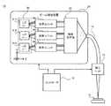
- FIG. 1is a diagram showing a configuration of a laser processing machine 1 according to the present embodiment.
- FIG. 1is a diagram illustrating the configuration of the laser processing machine 1 according to the present embodiment.
- the laser machining machine 1includes, for example, a beam coupling device 2, a transmission optical system 10, a machining head 11, and a controller 12.
- the laser processing machine 1is a device that irradiates various processing objects 15 with laser light to perform various laser processing.
- Various laser processesinclude, for example, laser welding, laser cutting, and laser perforation.
- the beam coupling device 2is a device that couples a plurality of light beams that emit light separately in order to supply the laser light of the laser processing machine 1, for example.
- the beam coupling device 2is configured by a wavelength synthesis formula that synthesizes a plurality of light beams while resonating at different wavelengths. According to the wavelength synthesis type beam coupling device 2, it is easy to obtain good beam quality and narrow down the beam diameter.
- the transmission optical system 10is an optical system that transmits the laser light from the beam coupling device 2 to the processing head 11, and includes, for example, an optical fiber.
- the processing head 11is, for example, a device that is arranged to face the processing object 15 and irradiates the processing object 15 with laser light transmitted from the beam coupling device 2.
- the controller 12is a control device that controls the overall operation of the laser processing machine 1.
- the controller 12includes, for example, a CPU or MPU that cooperates with software to realize a predetermined function.
- the controller 12may be provided with an internal memory for storing various programs and data, and various interfaces capable of inputting oscillation conditions and the like by the operation of the user.
- the controller 12may include hardware circuits such as ASIC and FPGA that realize various functions. Further, the controller 12 may be integrally configured with the drive circuit of the light source.
- Beam coupling device 2 of the present embodimentis, for example, as shown in FIG. 1, an LD bar 3 which is an example of a light source, an optical unit 4, a coupling lens 24, a diffraction element 25, and an output coupler 26. And.
- the beam coupling device 2 of the present embodimentconstitutes an external resonance type optical resonator that resonates light in an optical path that reciprocates between the LD bar 3 and the output coupler 26.
- the LD bar 3is composed of an array of light source elements including a plurality of LDs (laser diodes) 311 to 315 arranged one-dimensionally.
- the direction in which the LD311 to 315 are arrangedis defined as the "X direction”
- the direction of the optical axis of the light beam emitted by the LD bar 3 from the LD311 to 315is defined as the "Z direction”
- the directions orthogonal to the X and Z directionsIs the "Y direction”.
- FIG. 1illustrates three LDs 311, 313, 315 in the LD bar 3.
- the number of LD311 to 315 included in the LD bar 3is, for example, tens to hundreds.
- the plurality of LD311 to 315have a common spontaneous emission spectrum depending on, for example, the material of the LD light emitting layer (see FIG. 3).
- the generic name of LD311 to 315may be referred to as "LD31".
- Each LD 31is an example of a light source element constituting the emitter of the LD bar 3, and emits a light beam to the + Z side, respectively.
- the optical unit 4is an optical system that adjusts and guides a plurality of light beams from each LD 31 of the LD bar 3.
- the optical unit 4is arranged on the + Z side of the LD bar 3. According to the optical unit 4 of the present embodiment, the degree of freedom in design of the wavelength synthesis type beam coupling device 2 accompanied by a complicated optical design can be improved, and the beam coupling device 2 can be miniaturized. Details of the optical unit 4 will be described later.
- the coupling lens 24is arranged, for example, on the + Z side of the optical unit 4 with a distance D1.
- the distance D1 on the ⁇ Z side of the coupling lens 24is set to, for example, the focal length of the coupling lens 24.
- the diffraction element 25is arranged at a distance D2 from the coupling lens 24, for example, on the + Z side.
- the diffraction element 25is, for example, a dispersive element in which a transmission type diffraction grating is formed.
- the diffraction grating of the diffraction element 25satisfies the diffraction condition for emitting light beams from a plurality of LD311 to 315 in the same direction and coupling them.
- the diffraction condition of the diffraction element 25is expressed by, for example, the following equation (1).
- ⁇is the incident angle of the light beam incident on the diffraction element 25, and ⁇ is the diffraction angle of the light beam emitted after diffraction. Further, ⁇ is the wavelength of light to be diffracted and corresponds to the resonance wavelength. d is the pitch of the diffraction grating in the diffraction element 25. m indicates the diffraction order, for example, a natural number.
- FIG. 2is a diagram illustrating a method of coupling an optical beam in the diffraction element 25 of the beam coupling device 2.
- different resonance wavelengths ⁇are set in each of the LD311 to 315 so that the diffraction angles ⁇ of the LD311 to 315 are the same based on the above equation (1).
- the light beams from the plurality of LD311 to 315are emitted from the diffraction element 25 in the same direction after diffraction, and the light beam as a coupling result is obtained.
- FIG. 3is a graph showing the spectrum of the resonance wavelength ⁇ in the beam coupling device 2.
- the horizontal axisrepresents the wavelength [nm] and the vertical axis represents the intensity of light.
- FIG. 3shows the individual resonance spectra S1 to S3 in the plurality of LD311 to 315 in the LD bar 3 and the common spontaneous emission spectrum S0.
- Each resonance spectrum S1, S2, S3shows the distribution of the resonance wavelength ⁇ of each LD311, 313, 315.
- the spontaneous emission spectrum S0includes a wavelength band of 900 nm such as 955 nm to 990 nm. According to the resonance spectra S1 to S3, the resonance wavelength ⁇ becomes longer in order from LD311 to LD315 according to the positions arranged in the LD bar 3.
- the beam coupling device 2 of the present embodimentis a beam coupling device so that the resonance spectra S1 to S3 of all LD311 to 315 in the LD bar 3 fall within the range of the spontaneous emission spectrum S0. 2 various parameters are set.
- Various parameters of the beam coupling device 2are, for example, the pitch of LD311 to 315 in the LD bar 3, the focal length of the coupling lens 24, the shape of the diffraction grating in the diffraction element 25, and the distance between each part of the beam coupling device 2.
- the output coupler 26is arranged in the direction in which the light beam diffracted by the diffraction element 25 is emitted.
- the output coupler 26includes, for example, a mirror element having a predetermined transmittance and reflectance.
- the transmission component corresponding to the transmittanceis emitted to, for example, the transmission optical system 10 as the output of the beam coupling device 2.
- the reflection component corresponding to the reflectanceis returned to the diffraction element 25 for optical resonance.
- the output coupler 26may be provided with a mechanism capable of adjusting such reflectance and transmittance.
- the beam coupling device 2As described above, good beam quality can be obtained by performing wavelength synthesis type beam coupling as an external resonance type optical resonator.
- the external resonance type optical resonatorthat performs wavelength synthesis type beam coupling, there is a problem that the optical design becomes complicated and the apparatus configuration becomes large.
- the present embodimentprovides an optical unit 4 that can improve the degree of freedom in designing such an optical design and can reduce the size of the beam coupling device 2.
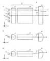
- FIG. 4Ashows a plan view of the beam coupling device 2 as viewed from the Y direction.
- FIG. 4Bshows a side view of the beam coupling device 2 as viewed from the X direction.
- the optical unit 4includes, for example, a BTU (beam twister unit) 40 arranged to face the LD bar 3 and a SAC (slow axis collimator) 45 arranged on the + Z side of the BTU 40.
- the coupling lens 24is composed of, for example, a cylindrical lens having a positive refractive power in the X direction.
- the BTU 40 and the SAC 45may be provided separately, and in this case, the BTU 40 is an example of the optical unit in the present embodiment.
- the distance D1 from the BTU 40 of the optical unit 4 to the coupling lens 24is set to the focal length Df of the coupling lens 24 from the viewpoint of collimating each light beam from the LD bar 3 as described above. ..
- the distance D2 from the coupling lens 24 to the diffraction element 25may be set from the viewpoint of condensing each light beam on the diffraction element 25.
- the BTU 40 of the optical unit 4controls the directions of a plurality of light beams from the LD bar 3.
- FIGS. 4A and 4Bexemplify the main ray L11 of the light beam from the outer LD311 and the main ray L13 of the light beam from the central LD313 in the LD bar 3, respectively.
- the central LD313has a main ray L13 that travels straight through the optical unit 4 and the coupling lens 24 and is parallel to the Z direction.
- the main ray L11 of the light beam from the outer LD311 in the LD bar 3is directed inward in the X direction.
- the main rays L11 and L13intersect, and a plurality of light beams can be focused. Therefore, the distance D2 to the diffraction element 25 can be shortened from the focal length Df, and the beam coupling device 2 can be miniaturized.
- the arrangement of the coupling lens 24can be changed by controlling the main ray directions of the plurality of light beams by the BTU 40.
- the focal length Df of the coupling lens 24can be set to an appropriate length from the viewpoint of collimation described above, and can be set to, for example, 1 m or more.
- a degree of freedom in designis also obtained so that the function of condensing light is realized by the cooperation of the BTU 40 and the coupling lens 24.
- the main ray L11 directed inward in the X direction by the BTU 40can be prevented from inward or outward in the Y direction, as shown in FIG. 4 (B). ..
- the incident angle of the light beam with respect to the output coupler 26changes, causing a problem in optical resonance. Conceivable.
- the light ray direction in the X directioncan be controlled without interfering with the light ray angle in the Y direction, and the above-mentioned problems can be avoided.
- optical unit 4 of the beam coupling device 2The details of the optical unit 4 of the beam coupling device 2 in the present embodiment will be described below.
- FIG. 5illustrates the basic configuration of the optical unit 4.
- FIG. 5Ashows a plan view of the optical unit 4 in the basic configuration.
- 5 (B)shows a side view of the optical unit 4 of FIG. 5 (A).
- the optical path of the light beam from one LD31such as the central LD313 is illustrated.
- the BTU 40 in the optical unit 4includes a BT (beam twister) 50 and a FAC (fast axis collimator) 41.
- FAC41, BT50, and SAC45are arranged in order from the vicinity of LD31 to the + Z side.
- the LD31emits a light beam having a fast axis Af and a slow axis As.
- the fast-axis Af of the light beamexpands the beam diameter more rapidly than the slow-axis As, and it is easy to obtain good beam quality.
- the fast axis Af of the light beamis oriented in the Y direction and the slow axis As is oriented in the X direction.
- the FAC 41is provided for collimating a light beam on the fast axis Af, and is composed of, for example, a cylindrical lens having a positive refractive power. As shown in FIGS. 5A and 5B, for example, the FAC 41 is arranged at a focal length position from the + Z side of the LD bar 3 with the longitudinal direction facing the X direction. In this example, the light beam from the LD 31 is collimated by the FAC 41 in the Y direction (that is, the fast axis Af) and is incident on the BT 50.
- FIG. 6shows a configuration example of the BT50.
- the BT 50is, for example, an optical element that rotates a plurality of light beams, and includes a plurality of oblique lens portions 51.
- the oblique lens portion 51is a portion of the BT50 that constitutes a lens for each LD31, and constitutes, for example, a cylindrical lens.
- the BT50 and the FAC41may be provided separately, and in this case, the BT50 is an example of the optical unit in the present embodiment.
- the BT50is formed so as to arrange a plurality of oblique lens portions 51 at a predetermined pitch in the X direction, for example.
- the oblique lens portion 51is tilted by 45 ° with respect to both the arrangement direction (that is, the X direction) and the thickness direction of the BT 50 (that is, the Y direction).
- the inclination of the oblique lens portion 51 in the BT 50does not necessarily have to be 45 °, and may be, for example, 40 ° to 50 ° with respect to the Y direction.
- the BT50rotates the light beam incident from the LD31 via the FAC41 by a rotation angle of 90 ° in the XY plane.
- the slow axis As of the light beam emitted from the BT50is oriented in the Y direction
- the fast axis Afis oriented in the X direction.
- the light beam at the time of emission of the BT50becomes divergent light in the Y direction and parallel light in the X direction.
- the SAC 45is provided to collimate the light beam on the slow axis As, and is composed of, for example, a cylindrical lens having a positive refractive power. As shown in FIGS. 5 (A) and 5 (B), the SAC 45 is arranged at a focal length position from the + Z side of the BTU 40 with the longitudinal direction facing the X direction. In this example, the light beam from the BT50 is collimated by the SAC45 in the Y direction (that is, the slow axis As) and emits the optical unit 4.
- the light beam emitted from each LD 31 of the LD bar 3is basically collimated in the fast axis Af and the slow axis As.
- the beam diametercan be widened as an effect of waves from the + Z side surface of the BT50, especially in the fast axis Af.
- the above-mentioned influencecan be suppressed by collimating each light beam by the coupling lens 24.
- BT of optical unitvarious main rays are controlled by adjusting the arrangement of the oblique lens portion 51 in the BT50 while utilizing the basic functions of each portion of the optical unit 4 as described above. To realize. Hereinafter, a configuration example of such an optical unit 4 will be described.
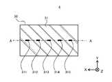
- FIG. 7shows a configuration example of the BT50 of the optical unit 4 in this embodiment.
- FIG. 7shows a front view of the optical unit 4 as viewed from the ⁇ Z side together with the plurality of LDs 311, 312, 313, 314, 315.
- the light beams from the LDs 311 to 315pass through the opposing lens portions 51 from the ⁇ Z side to the + Z side, for example, with the Z direction as the optical axis direction.
- the BT50 of the present embodimentis configured by shifting the pitch of the oblique lens portion 51 between the emission side and the incident side, that is, both end faces of the ⁇ Z side of the light beam from each LD31.
- FIG. 8shows a cross-sectional view of the XZ plane in the BT50 of FIG.
- the BT50 of this configuration exampleis configured so that the pitch Wo between the oblique lens portions 51 on the end face on the + Z side is smaller than the pitch Wi on the end face on the ⁇ Z side.
- the pitch Wi on the ⁇ Z sideis set to be the same as the pitch between the LDs 31 in the LD bar 3, for example.
- the center of the central oblique lens portion 51matches on both sides on the ⁇ Z side.
- the difference between the pitches Wi and Wois set to be sufficiently smaller than, for example, each pitch Wi and Wo, and is, for example, 0.1 times or less of each pitch Wi and Wo.
- the difference between the pitch Wi and Womay be set in consideration of the number of oblique lens portions 51 or LD31.
- the difference between the pitches Wi and Wois, for example, 0.0001 times or more the respective pitches Wi and Wo.
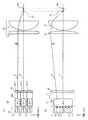
- 9 (A) to 9 (C)exemplify the optical path in the optical unit 4 of this configuration example.
- 9 (A)corresponds to the AA cross section of the optical unit 4 of FIG.
- the AA cross sectionis an XZ plane in which each LD311 to 315 of the LD bar 3 is located.
- 9 (B) and 9 (C)correspond to the BB sectional view and the CC sectional view in FIG. 9 (A), respectively.
- the BB cross sectionis the YZ plane where the central LD313 is located.
- the CC cross sectionis the YZ plane on which the outer LD315 is located.
- the main light beam of the light beam from each LD31reaches the + Z side surface of the BT50 after being incident on the FAC41. Go straight along the Z direction until you reach the front.
- the LD31a located outside in the X directionhas the main ray La inward in the X direction and in the Y direction. Can also tilt.
- Each main ray La, Lcreaches SAC45 when BT50 is emitted.
- the SAC 45collimates the light beam in the Y direction
- the inclination of the main ray Lc in the Y directionis corrected in the SAC 45 as shown in FIG. 9C.
- the main ray Lc of the outer LD31c in the X directioncan be restricted in the X direction and directed inward.
- the focal length of the SAC 45was set to 50 mm
- the focal length of the coupling lens 24was set to 1130 mm
- the pitch between the LDs 31 of the LD bar 3was set to 0.225000 mm.
- the pitch Wo on the + Z side of the BT50is set to be 230 nm smaller than the pitch Wi on the ⁇ Z side.
- the pitch Wi on the ⁇ Z side of the BT50was set to be the same as the pitch between the LDs of the LD bar 3.
- FIG. 10Ashows the simulation result of the beam coupling device 2 of the present embodiment.
- the numerical calculation of the main ray on the + X sidewas performed.
- Each row in the figureshows the numerical calculation result when the main ray passes through each part of the beam coupling device 2 for each surface number from the object side (that is, -Z side) to the image side (that is, + Z side).
- "X"indicates the X coordinate
- "Y”indicates the Y coordinate
- TANXindicates the slope in the XZ plane with the tan function
- TANYindicates the slope in the YZ plane with the tan function.
- the position of the LD31 corresponding to the numerically calculated main raywas 4 mm in X coordinate.
- FIG. 10Bshows a simulation result of a comparative example with respect to FIG. 10A.
- the same numerical calculation as in FIG. 10Awas performed when the BTU pitch was not shifted on both sides of the ⁇ Z side and instead the BTU was rotated in the XY plane.
- a technique for introverting an outer main ray by rotating an optical element such as BTUhas been conventionally known (for example, Patent Document 1).
- the rotation angle of BTUwas set to 0.008 °.
- the value "-0.00346" of "TANX” after the injection of SACis equivalent to the example of FIG. 10 (A).
- "TANY”has a value of "0.0007" after the injection of SAC. That is, in this comparative example, when the outer main ray is directed inward in the X direction, there is an effect of causing an inclination in the Y direction. From the above, it was confirmed that the optical unit 4 of the present embodiment can realize the inward direction of the outer main ray in the X direction while suppressing the influence in the Y direction as compared with the conventional technique.
- the optical unit 4 in the present embodimentguides a plurality of light beams.
- the BT50 of the optical unit 4includes a plurality of oblique lens units 51 as an example of a plurality of lens units through which a plurality of light beams are transmitted.
- the plurality of oblique lens portions 51are arranged in an arrangement direction (for example, the X direction) that intersects the optical axis direction (for example, the Z direction) through which the light beam is transmitted.
- Each oblique lens portion 51is inclined with respect to a thickness direction (for example, the Y direction) that intersects the optical axis direction and the arrangement direction.
- the pitch Wo in which the oblique lens portions 51 are arranged on the end face on the + Z side as an example of one end face of both end faces of the BT50 in the optical axis directionis used as the other end face. It is smaller than the pitch Wi in which the oblique lens portions 51 are arranged on the end face on the ⁇ Z side of the above.
- the oblique lens unit 51 on the + Z sidesince the pitch Wo of the light beam becomes smaller, the main ray L11 of the light beam outside in the X direction can be directed inward. Therefore, it is possible to control the direction of light rays that guide the light beam so as to condense a plurality of light beams. In this way, the BT50 of the optical unit 4 can improve the degree of freedom in design for guiding a plurality of light beams.
- the BTU 40 of the optical unit 4includes a FAC 41 as an example of the first collimator lens.
- the FAC 41is arranged to face the end face on the ⁇ Z side, which is one end face of both end faces on the ⁇ Z side of the BT50, and causes a light beam to be incident on the oblique lens portion 51 from the end face.
- itis possible to control the light direction of a plurality of light beams incident from the FAC 41.
- the optical unit 4further includes a SAC 45 as an example of the second collimator lens.
- the SAC 45is arranged to face the end face on the + Z side of both end faces of the BT 50, which is the side opposite to the end face facing the FAC 41, and collimates the light beam emitted from the end face. According to the SAC 45, it is possible to correct the light ray direction of the light beam whose light ray direction is changed in the BT50 after being incident from the FAC 41, and it is possible to easily control the light ray direction of the plurality of light beams.
- the beam coupling device 2 in the present embodimentincludes an LD bar 3 as an example of a light source, an optical unit 4, and a diffraction element 25.
- the LD bar 3includes LD311 to 313 as a plurality of light source elements capable of resonating with each other at different wavelengths, and emits a plurality of light beams from each of the LD311 to 313.
- the optical unit 4guides each light beam from the LD bar 3.
- the diffraction element 25diffracts each light beam incident from the LD bar 3 via the optical unit 4 and combines a plurality of light beams that resonate at different wavelengths.
- the optical unit 4is arranged so that the end face on the + Z side of the both end faces of the BT 50, which has a small pitch Wo of the oblique lens portion 51, faces the diffraction element 25.
- the optical unit 4when a plurality of light beams resonating at different wavelengths are diffracted and coupled by the diffraction element 25, the optical unit 4 can focus the plurality of light beams on the diffraction element 25.
- the device configuration of the beam coupling device 2can be miniaturized.
- the wavelength of resonance via the diffraction element 25 for each LD 31gradually changes according to the position of each LD 31 in the X direction, which is the arrangement direction.
- the resonance wavelength ⁇becomes longer from LD311 on the + X side to LD315 on the ⁇ X side.
- the light beams from each LD 31can be coupled via the diffraction element 25.
- the pitch between the plurality of LD31s in the arrangement direction and the pitch Wi in which the oblique lens portions 51 are arranged on the end face on the ⁇ Z side, which is closer to the light source among both end faces of the optical unit 2BTU40,are Match. Thereby, the light beam from each LD 31 can be appropriately controlled.
- the laser machining machine 1 in the present embodimentincludes a beam coupling device 2 and a machining head 11 that irradiates a machining object with a light beam coupled by the beam coupling device 2.
- the laser processing machine 1 of the present embodimentcan be configured by using the wavelength synthesis type beam coupling device 2 which has been downsized from the improvement of the degree of freedom in design for guiding a plurality of light beams by the optical unit 4.
- FIG. 11is a diagram illustrating the configuration of the laser processing machine 1A according to the second embodiment.
- the laser processing machine 1 of the present embodimenthas the same configuration as the laser processing machine 1 of the first embodiment, and includes a space synthesis type beam coupling device 2A instead of the wavelength synthesis type beam coupling device 2.
- the beam coupling device 2A in the present embodimentincludes a laser light source 30, a plurality of optical units 4A-1 to 4A-3, and a coupling optical system 20.
- the laser light source 30includes a plurality of LD bars 3-1 to 3-3 in the present embodiment.
- Each of the LD bars 3-1 to 3-3is configured in the same manner as the LD bar 3 of the first embodiment, for example.
- the LD bars 3-1 to 3-3may be collectively referred to as "LD bar 3”
- the optical units 4A-1 to 4A-3may be collectively referred to as "optical unit 4A".
- the plurality of LD bars 3are arranged side by side in the Y direction orthogonal to the X direction, for example, the arrangement direction of each LD is set to be parallel to the X direction.
- the number of LD bars 3 in the beam coupling device 2Ais shown in the example of three, but is not particularly limited, and may be two or four or more.
- the beam coupling device 2A of the present embodimentis configured by a space synthesis formula that couples a large number of light beams emitted by each LD 31 of a plurality of LD bars 3 spatially arranged in the laser light source 30.
- the present embodimentprovides a beam coupling device 2A capable of performing beam coupling at a high density with a small beam diameter.
- a plurality of optical units 4Aare provided, for example, for the number of LD bars 3.
- One optical unit 4Aguides the light beam from each LD by one LD bar 3 to the coupling optical system 20.
- the coupling optical system 20is an optical system that couples the light beams from each optical unit 4A in the beam coupling device 2A.
- FIG. 12is a diagram showing the configuration of the beam coupling device 2A according to the second embodiment.
- FIG. 12Ashows a side view of the beam coupling device 2A as viewed from the X direction.
- FIG. 12Bshows a plan view of the beam coupling device 2A as viewed from the Y direction.
- each LD bar 3is arranged on the ⁇ Z side of the separate optical unit 4A.
- the configuration of the BTU 40Ais different from the configuration of the optical unit 4 of the first embodiment.
- the coupled optical system 20is arranged on the + Z side of the optical unit 4A and includes an axisymmetric condensing lens 21 and a cylindrical lens 22 arranged between the condensing lens 21 and the optical unit 4A.
- FIG. 12Billustrates the five LD31a, 31b, 31c, 31d, and 31e in the LD bar 3.
- the resonance wavelengths of the individual LDs 31a to 31emay be the same.
- the plurality of LDs 31a to 31e in the LD bar 3are an example of a set of light source elements in the laser light source 30 of the present embodiment.
- the generic name of LD31a to 31emay be referred to as "LD31".
- the beam coupling position P1is set to a position where the beam diameter including the light beam emitted from each of the LDs 31a to 31e of all the LD bars 3-1 to 3-3 is minimized, for example.
- the incident end of the optical fiber of the transmission optical system 10 described aboveis arranged at the beam coupling position P1.
- FIG. 12Aillustrates the main ray L1 of the light beam from the outer LD bar 3-1 in the Y direction and the main ray L2 of the light beam from the central LD bar 3-2.
- FIG. 12Billustrates the main ray La of the light beam from the outer LD31a in the X direction and the main ray Lc of the light beam from the central LD31c.
- the central LD31c in the X and Y directionshas a main ray Lc parallel to the Z direction as in the first embodiment.
- the outer LD bars 3-1 of the plurality of LD bars 3 arranged in the Y directionemit light.
- the main ray L1 of the light beamis directed inward.
- Such light ray controlcan be performed by tilting the direction of the outer optical unit 4A-1 or shifting the arrangement of the SAC 45 inward.
- the optical unit 4A on the upper side (+ Y side) in the drawingtilts the main ray L1 of the light beam from the Z direction to the lower side ( ⁇ Y side).
- the beam coupling position P1 in the Y direction where the main rays L1 and L2 intersect between the LD bars 3is located on the ⁇ Z side of the focal position P0 of the condenser lens 21.
- the optical unit 4A of the beam coupling device 2A of the present embodimentis a light beam from the outer LD31a. It is configured to direct the main ray La outward.
- the position where the plurality of light beams intersectcan be brought closer to the focal point of the condenser lens 21, the beam diameter itself at the time of coupling each light beam can be reduced, and the density of the light beam incident on the coupled optical system 20 can be increased. be able to.
- the beam coupling position P1can match the beam coupling position P1 in the X direction and the Y direction.
- optical unit 4A of the beam coupling device 2A according to the second embodimentwill be described.
- FIG. 13shows a configuration example of the BT50A of the optical unit 4A in the second embodiment.
- the optical unit 4A of the present embodimentincludes, for example, the BT50A of the configuration example of FIG. 13 in place of the BT50 in the optical unit 4 of the first embodiment, in which the pitch Wo on the + Z side is smaller than the pitch Wi on the ⁇ Z side.
- FIG. 14shows a cross-sectional view of the XZ plane in the BT50A of FIG.
- the pitch Wi on the ⁇ Z sideis smaller than the pitch Wo on the + Z side.
- the BT50A of this configuration exampleis configured so that the pitch Wo between the oblique lens portions 51 on the end face on the + Z side is larger than the pitch Wi on the end face on the ⁇ Z side.
- the curved surface shape of the oblique lens portion 51 on the end face on the + Z sidecan be set to extend, for example, the curved surface shape on the ⁇ Z side.
- the pitch Wi on the ⁇ Z sideis set according to the pitch between the LDs 31 in the LD bar 3 as in the BT50 of the first embodiment, for example. Further, the magnitude of the difference between the pitches Wi and Wo may be within the same range as that of the first embodiment.
- the BT50A and BTU40A of the present embodimentare also examples of optical units, respectively, as in the first embodiment.
- FIG. 15 (A) to 15 (C)illustrate the optical path in the optical unit 4A of the present embodiment in the same manner as in FIGS. 9 (A) to 9 (C).
- FIG. 15Acorresponds to the AA cross section of FIG. 15 (B) and 15 (C) correspond to the BB sectional view and the CC sectional view in FIG. 15 (A), respectively.
- the BT50A of the present embodimentfaces the SAC45 on the + Z side and faces the FAC41 on the ⁇ Z side, as in the first embodiment.
- the main light beam of the light beam from each LD31is larger than the pitch between the LD31s at the end face on the + Z side of the BT50A. Due to the pitch Wo of the oblique lens portion 51, the main ray La is directed outward in the X and Y directions as the LD31a is located outside in the X direction. As shown in FIG. 15C, the inclination of the main ray La in the Y direction is corrected in the SAC 45 in the same manner as in the first embodiment.
- the main ray Lc of the outer LD31c in the X directioncan be restricted in the X direction and directed outward.
- FIG. 16shows a simulation result as an embodiment of the beam coupling device 2A of the second embodiment.
- the same numerical calculation as in the first embodimentwas performed in the simulation environment of the space synthesis type beam coupling device 2A.
- the distance between the plurality of optical units 4Awas set to 4.8 mm
- the focal length of the SAC 45was set to 15 mm
- the focal length of the condenser lens 21was set to 50 mm.
- the same numerical calculation as in the first embodimentwas performed with the setting that the pitch Wo on the + Z side of the BT50A was made larger by 318 nm than the pitch Wi on the ⁇ Z side.
- the pitch between the pitch Wi on the ⁇ Z side of the BT50A and the LD of the LD bar 3was 0.225000 mm as in the first embodiment.
- TANXhas a positive value of "0.00443" after the injection of SAC45, and the main ray on the + X side is outward. Further, the value "0.00003" of "TANY” at this time is sufficiently smaller than the above-mentioned "TANX”. Therefore, it was confirmed that the main ray outside in the X direction can be directed outward in the X direction while keeping the inclination in the Y direction slightly.
- Wiis smaller than the pitch Wo in which the oblique lens portions 51 are arranged on the end face on the + Z side as an example of the other end face.
- the oblique lens unit 51 on the + Z sidesince the pitch Wo of the light beam becomes large, the main ray La of the light beam outside in the X direction can be directed outward. In this way, the BT50A of the optical unit 4A can improve the degree of freedom in design for guiding a plurality of light beams.
- the beam coupling device 2A in the present embodimentincludes a laser light source 30, a plurality of optical units 4A, and a coupling optical system 20 as an example of a light source.
- the laser light source 30includes, for example, LD31 which is an example of a plurality of light source elements arranged in the X direction and the Y direction.
- the plurality of optical units 4Aguide each light beam to each of the LD bars 3 as a set of LD31a to LD31e arranged in the X direction in the laser light source 30.
- the coupling optical system 20couples a plurality of light beams guided to each optical unit 4A.
- the optical unit 4Ais arranged so that the end face on the + Z side of the both end faces of the BT 50, which has a large pitch Wo of the oblique lens portion 51, faces the coupling optical system 20.
- the beam diameter itself at the beam coupling position P1can be reduced by outwardly directing the main ray L11 outside in the X direction by the optical unit 4A. ..
- the beam qualitycan be improved in the space synthesis type beam coupling device 2A.
- Embodiments 1 and 2have been described as examples of the techniques disclosed in this application. However, the technique in the present disclosure is not limited to this, and can be applied to embodiments in which changes, substitutions, additions, omissions, etc. are made as appropriate. It is also possible to combine the components described in each of the above embodiments into a new embodiment. Therefore, other embodiments will be illustrated below.
- the configuration of the beam coupling device 2is not particularly limited to this example.
- a transmission type diffraction element 25is used for the beam coupling device 2
- the diffraction element 25is not limited to the transmission side and may be a reflection type.
- the 900 nm bandis illustrated as the wavelength band in which the LD 31 emits light, but the wavelength band of the LD 31 is not particularly limited and may be, for example, the 400 nm band.
- the light beam direction of the light beamcan be controlled such that the BT50 takes charge of the focusing function, and the degree of freedom in design is improved. can do.
- the configuration of the beam coupling device 2Ais not particularly limited to this example.
- the beam coupling device 2A for inwardly directing the outer main ray L1 in the Y directionhas been described, the main ray L1 may not be inwardly directed, for example, may be outwardly directed.
- the cylindrical lens 22 for the coupling optical system 20has been described, the cylindrical lens 22 may be omitted. According to the optical unit 4A of the present embodiment, the degree of freedom in design can be improved even in the optical design of the various spatial synthesis type beam coupling devices 2A.
- optical unit of the present embodimentis not limited to the wavelength synthesis type or the space synthesis type, and may be applied to various beam coupling devices.
- the optical unit of the present embodimentcan also be applied to a beam coupling device in which a wavelength synthesis type and a space synthesis type are appropriately combined.
- the present disclosureis applicable to various applications in which a plurality of light beams are combined and used, and is applicable to, for example, various laser processing technologies.
Landscapes
- Physics & Mathematics (AREA)
- Optics & Photonics (AREA)
- General Physics & Mathematics (AREA)
- Condensed Matter Physics & Semiconductors (AREA)
- Electromagnetism (AREA)
- Engineering & Computer Science (AREA)
- Plasma & Fusion (AREA)
- Mechanical Engineering (AREA)
- Optical Couplings Of Light Guides (AREA)
- Semiconductor Lasers (AREA)
- Diffracting Gratings Or Hologram Optical Elements (AREA)
- Laser Beam Processing (AREA)
Abstract
Description
Translated fromJapanese本開示は、光学ユニット、及び光学ユニットを備えたビーム結合装置、並びにビーム結合装置を備えたレーザ加工機に関する。The present disclosure relates to an optical unit, a beam coupling device including the optical unit, and a laser processing machine equipped with the beam coupling device.
特許文献1は、個々の光ビームを重ね合わせて結合ビームを形成する波長合成式のレーザシステムを開示している。特許文献1では、光出力を増大する観点より、複数のダイオードバーからの光ビームを光ファイバに集光することが開示されている。また、レーザシステムを小型化する目的から、波長合成における結合レンズの配置を焦点距離から外すための光学系を別途含めたり、ビーム回転子を回転させたりしている。
本開示は、複数の光ビームを導光する設計自由度を向上することができる光学ユニット、ビーム結合装置及びレーザ加工機を提供する。The present disclosure provides an optical unit, a beam coupling device, and a laser processing machine that can improve the degree of freedom in design for guiding a plurality of light beams.
本開示に係る光学ユニットは、複数の光ビームを導光する。光学ユニットは、複数の光ビームがそれぞれ透過する複数のレンズ部を備える。複数のレンズ部は、光ビームが透過する光軸方向と交差する配列方向に配列される。各レンズ部は、光軸方向及び配列方向と交差する厚み方向に対して傾斜している。光軸方向における光学ユニットの両端面のうちの、一方の端面においてレンズ部が配列されたピッチが、他方の端面においてレンズ部が配列されたピッチよりも小さい。The optical unit according to the present disclosure guides a plurality of light beams. The optical unit includes a plurality of lens units through which a plurality of light beams are transmitted. The plurality of lens units are arranged in an arrangement direction that intersects the optical axis direction through which the light beam is transmitted. Each lens portion is inclined with respect to the thickness direction intersecting the optical axis direction and the arrangement direction. Of both end faces of the optical unit in the optical axis direction, the pitch at which the lens portions are arranged on one end face is smaller than the pitch at which the lens portions are arranged at the other end face.
本開示の一態様に係るビーム結合装置は、互いに異なる波長で共振可能な複数の光源素子を含む光源と、上記の光学ユニットと、回折素子とを備える。光源は、各光源素子からの複数の光ビームを発光する。光学ユニットは、光源からの各光ビームを導光する。回折素子は、光源から光学ユニットを介して入射する各光ビームを回折して、異なった波長で共振する複数の光ビームを結合する。光学ユニットが、両端面のうちのレンズ部のピッチが小さい端面を回折素子に向けて配置される。The beam coupling device according to one aspect of the present disclosure includes a light source including a plurality of light source elements capable of resonating at different wavelengths, the above optical unit, and a diffraction element. The light source emits a plurality of light beams from each light source element. The optical unit guides each light beam from the light source. The diffraction element diffracts each light beam incident from the light source via the optical unit, and combines a plurality of light beams that resonate at different wavelengths. The optical unit is arranged so that the end faces of both end faces having a small pitch of the lens portion are directed toward the diffraction element.
本開示の別の態様に係るビーム結合装置は、配列方向及び厚み方向に並ぶ複数の光源素子を含む光源と、複数の上記光学ユニットと、結合光学系とを備える。光源は、各光源素子からの複数の光ビームを発光する。複数の光学ユニットは、光源において配列方向に並んだ光源素子の組毎に、各光ビームを導光する。結合光学系は、各光学ユニットに導光された複数の光ビームを結合する。光学ユニットが、両端面のうちのレンズ部のピッチが大きい端面を結合光学系に向けて配置される。The beam coupling device according to another aspect of the present disclosure includes a light source including a plurality of light source elements arranged in the arrangement direction and the thickness direction, the plurality of optical units, and a coupling optical system. The light source emits a plurality of light beams from each light source element. The plurality of optical units guide each light beam for each set of light source elements arranged in the array direction in the light source. The coupled optical system couples a plurality of light beams guided to each optical unit. The optical unit is arranged so that the end faces of both end faces having a large pitch of the lens portion are directed toward the coupling optical system.
本開示に係るレーザ加工機は、上記いずれかのビーム結合装置と、ビーム結合装置によって結合された光ビームを加工対象物に照射する加工ヘッドとを備える。The laser machining machine according to the present disclosure includes any of the above beam coupling devices and a machining head that irradiates a machining object with a light beam coupled by the beam coupling device.
本開示に係る光学ユニット、ビーム結合装置及びレーザ加工機によると、複数の光ビームを導光する設計自由度を向上することができる。According to the optical unit, the beam coupling device, and the laser processing machine according to the present disclosure, the degree of freedom in design for guiding a plurality of light beams can be improved.
以下、適宜図面を参照しながら、実施の形態を詳細に説明する。但し、必要以上に詳細な説明は省略する場合がある。例えば、既によく知られた事項の詳細説明や実質的に同一の構成に対する重複説明を省略する場合がある。これは、以下の説明が不必要に冗長になるのを避け、当業者の理解を容易にするためである。Hereinafter, embodiments will be described in detail with reference to the drawings as appropriate. However, more detailed explanation than necessary may be omitted. For example, detailed explanations of already well-known matters and duplicate explanations for substantially the same configuration may be omitted. This is to avoid unnecessary redundancy of the following description and to facilitate the understanding of those skilled in the art.
なお、出願人は、当業者が本開示を十分に理解するために添付図面および以下の説明を提供するのであって、これらによって特許請求の範囲に記載の主題を限定することを意図するものではない。It should be noted that the applicant is not intended to limit the subject matter described in the claims by those skilled in the art by providing the accompanying drawings and the following description in order to fully understand the present disclosure. Absent.
(実施形態1)
実施形態1では、波長合成式のビーム結合装置及びそれを備えたレーザ加工機に、光学ユニットを適用する例について説明する。(Embodiment 1)
In the first embodiment, an example in which the optical unit is applied to the wavelength synthesis type beam coupling device and the laser processing machine provided with the beam coupling device will be described.
1.レーザ加工機について
実施形態1に係るレーザ加工機及びビーム結合装置の構成について、図1を用いて説明する。図1は、本実施形態に係るレーザ加工機1の構成を示す図である。1. 1. Laser Machining Machine The configuration of the laser machining machine and the beam coupling device according to the first embodiment will be described with reference to FIG. FIG. 1 is a diagram showing a configuration of a
図1は、本実施形態に係るレーザ加工機1の構成を例示する図である。レーザ加工機1は、例えば、ビーム結合装置2と、伝送光学系10と、加工ヘッド11と、コントローラ12とを備える。レーザ加工機1は、レーザ光を種々の加工対象物15に照射して、各種レーザ加工を行う装置である。各種レーザ加工は、例えばレーザ溶接、レーザ切断、及びレーザ穿孔などを含む。FIG. 1 is a diagram illustrating the configuration of the
ビーム結合装置2は、例えばレーザ加工機1のレーザ光を供給するために、別個に発光する複数の光ビームを結合する装置である。本実施形態において、ビーム結合装置2は、複数の光ビームを、互いに異なる波長において共振させながら合成する波長合成式で構成される。波長合成式のビーム結合装置2によると、良好なビーム品質を得やすく、ビーム径を絞り易い。The
レーザ加工機1において、伝送光学系10は、ビーム結合装置2からのレーザ光を加工ヘッド11に伝送する光学系であり、例えば光ファイバを含む。加工ヘッド11は、例えば加工対象物15に対向して配置され、ビーム結合装置2から伝送されたレーザ光を加工対象物15に照射する装置である。In the
コントローラ12は、レーザ加工機1の全体動作を制御する制御装置である。コントローラ12は、例えばソフトウェアと協働して所定の機能を実現するCPU又はMPUを備える。コントローラ12は、各種プログラム及びデータを記憶する内部メモリ、及び使用者の操作により発振条件等を入力可能な各種インタフェースを備えてもよい。コントローラ12は、各種機能を実現するASIC,FPGA等のハードウェア回路を備えてもよい。また、コントローラ12は、光源の駆動回路と一体的に構成されてもよい。The
1-1.ビーム結合装置について
本実施形態のビーム結合装置2は、例えば図1に示すように、光源の一例であるLDバー3と、光学ユニット4と、結合レンズ24と、回折素子25と、出力カプラ26とを備える。本実施形態のビーム結合装置2は、LDバー3と出力カプラ26との間を往復する光路において、光を共振させる外部共振型の光共振器を構成する。1-1. Beam coupling device The
LDバー3は、一次元的に配列された複数のLD(レーザダイオード)311~315を含む光源素子のアレイで構成される。以下では、LD311~315が配列された方向を「X方向」とし、LDバー3がLD311~315から射出する光ビームの光軸の方向を「Z方向」とし、X,Z方向に直交する方向を「Y方向」とする。The
図1では、LDバー3における3個のLD311,313,315を例示している。LDバー3に含まれるLD311~315の個数は、例えば数十個から数百個である。複数のLD311~315は、例えばLD発光層の材質に応じた共通の自然放出スペクトルを有する(図3参照)。以下、LD311~315の総称を「LD31」という場合がある。各LD31は、LDバー3のエミッタを構成する光源素子の一例であり、それぞれ+Z側に光ビームを射出する。FIG. 1 illustrates three
光学ユニット4は、LDバー3の各LD31からの複数の光ビームをそれぞれ調整して導光する光学系である。光学ユニット4は、LDバー3の+Z側に配置される。本実施形態の光学ユニット4によると、複雑な光学設計を伴う波長合成式のビーム結合装置2における設計自由度を向上して、ビーム結合装置2を小型化することができる。光学ユニット4の詳細については後述する。The
結合レンズ24は、例えば光学ユニット4の+Z側に距離D1を置いて配置される。結合レンズ24の-Z側の距離D1は、例えば結合レンズ24の焦点距離に設定される。LDバー3の各LD31からの複数の光ビームは、光学ユニット4を介して結合レンズ24に入射すると、結合レンズ24から+Z側に距離D2を置いた位置に集光する。結合レンズ24は、こうした集光時に各光ビームをそれぞれコリメートする。The
回折素子25は、例えば結合レンズ24から+Z側に距離D2の位置に配置される。回折素子25は、例えば透過型の回折格子が形成された分散性素子である。本実施形態において、回折素子25の回折格子は、複数のLD311~315からの光ビームを同じ方向に射出して、結合するための回折条件を満たす。回折素子25の回折条件は、例えば次式(1)のように表される。The
sinα+sinβ=mλ/d …(1)
ここで、αは回折素子25に入射する光ビームの入射角であり、βは回折後に射出する光ビームの回折角である。また、λは回折させる光の波長であり、共振波長に対応する。dは、回折素子25における回折格子のピッチである。mは、回折次数を示し、例えば自然数である。sinα + sinβ = mλ / d… (1)
Here, α is the incident angle of the light beam incident on the
図2は、ビーム結合装置2の回折素子25における光ビームの結合方法を説明した図である。回折素子25においては、図2に示すように、各LD311,313,315からの光ビームの入射角α=α1,α2,α3が互いに異なる。本実施形態のビーム結合装置2では、上式(1)に基づいて、各LD311~315の回折角βを同一にするように、各LD311~315に異なる共振波長λが設定される。これにより、複数のLD311~315からの光ビームは、回折後に回折素子25から同じ方向に射出して、結合結果の光ビームが得られる。FIG. 2 is a diagram illustrating a method of coupling an optical beam in the
図3は、ビーム結合装置2における共振波長λのスペクトルを示すグラフである。図3のグラフにおいて、横軸は波長[nm]を示し、縦軸は光の強度を示す。FIG. 3 is a graph showing the spectrum of the resonance wavelength λ in the
図3では、LDバー3における複数のLD311~315における個々の共振スペクトルS1~S3と、共通の自然放出スペクトルS0とを示している。各共振スペクトルS1,S2,S3は、各々のLD311,313,315の共振波長λの分布を示す。自然放出スペクトルS0は、例えば955nm~990nmといった900nm帯の波長帯を含む。共振スペクトルS1~S3によると、LDバー3において配列された位置に応じてLD311からLD315へと順番に、共振波長λが長くなっている。FIG. 3 shows the individual resonance spectra S1 to S3 in the plurality of LD311 to 315 in the
本実施形態のビーム結合装置2は、図3に示すように、LDバー3中の全てのLD311~315の共振スペクトルS1~S3が、自然放出スペクトルS0の範囲内に収まるように、ビーム結合装置2の各種パラメータが設定される。ビーム結合装置2の各種パラメータは、例えば、LDバー3におけるLD311~315のピッチ、結合レンズ24の焦点距離、回折素子25における回折格子の形状、ビーム結合装置2の各部間の距離である。As shown in FIG. 3, the
図1に戻り、出力カプラ26は、回折素子25において回折された光ビームが射出する方向に配置される。出力カプラ26は、例えば所定の透過率及び反射率を有するミラー素子等を含む。回折素子25から出力カプラ26に入射する光ビームのうち、透過率に応じた透過成分は、ビーム結合装置2の出力として、例えば伝送光学系10に射出する。一方、反射率に応じた反射成分は、光共振のために回折素子25に戻される。出力カプラ26には、こうした反射率及び透過率が調整可能な機構が設けられてもよい。Returning to FIG. 1, the
以上のようなビーム結合装置2によると、外部共振型の光共振器として波長合成式のビーム結合を行って、良好なビーム品質を得ることができる。その一方で、波長合成式のビーム結合を行う外部共振型の光共振器においては、光学設計が複雑になり、装置構成の大型化を招くといった課題がある。これに対して、本実施形態では、こうした光学設計の設計自由度を向上し、ビーム結合装置2を小型化できる光学ユニット4を提供する。According to the
1-1-1.ビーム結合装置の詳細
本実施形態に係るビーム結合装置2の構成の詳細を、図4を用いて説明する。図4(A)は、ビーム結合装置2をY方向から見た平面図を示す。図4(B)は、ビーム結合装置2をX方向から見た側面図を示す。1-1-1. Details of the Beam Coupling Device The details of the configuration of the
本実施形態のビーム結合装置2において、光学ユニット4は、例えば、LDバー3に対向配置されるBTU(ビームツイスタユニット)40と、BTU40の+Z側に配置されるSAC(スロー軸コリメータ)45とを含む。結合レンズ24は、例えばX方向において正の屈折力を有するシリンドリカルレンズで構成される。なお、BTU40とSAC45とは別体で提供されてもよく、この場合においてBTU40は本実施形態における光学ユニットの一例である。In the
本実施形態において、例えば光学ユニット4のBTU40から結合レンズ24までの距離D1は、上述したようにLDバー3からの各光ビームのコリメートの観点から、結合レンズ24の焦点距離Dfに設定される。一方、結合レンズ24から回折素子25までの距離D2は、各光ビームを回折素子25に集光する観点から設定することが考えられる。In the present embodiment, for example, the distance D1 from the
ここで、LDバー3からの複数の光ビームが互いに平行なまま結合レンズ24に入射するような場合、上記集光の観点から回折素子25までの距離D2も焦点距離Dfだけ取る必要が生じ、装置構成が大型化してしまう。そこで、本実施形態では、光学ユニット4のBTU40により、LDバー3からの複数の光ビームの向きを制御する。Here, when a plurality of light beams from the
図4(A),(B)では、それぞれLDバー3における外側のLD311からの光ビームの主光線L11と、中央のLD313からの光ビームの主光線L13とを例示している。本実施形態のビーム結合装置2において、例えば中央のLD313は、光学ユニット4及び結合レンズ24を直進し、Z方向に平行な主光線L13を有する。FIGS. 4A and 4B exemplify the main ray L11 of the light beam from the outer LD311 and the main ray L13 of the light beam from the central LD313 in the
本実施形態のBTU40によると、図4(A)に示すように、LDバー3における外側のLD311からの光ビームの主光線L11をX方向に内向させる。これにより、例えば結合レンズ24から焦点距離Dfよりも短い距離D2において、各主光線L11,L13が交差し、複数の光ビームを集光させることができる。よって、回折素子25までの距離D2を焦点距離Dfよりも短縮し、ビーム結合装置2を小型化することができる。According to the
又、BTU40が複数の光ビームの主光線方向を制御することで、結合レンズ24の配置を変えることができる。例えば、結合レンズ24の焦点距離Dfが、上述したコリメートの観点から適切な長さに設定可能となり、例えば1m以上等にも設定可能である。その一方で、集光の機能が、BTU40と結合レンズ24との協働によって実現されるような設計自由度も得られる。Further, the arrangement of the
また、本実施形態の光学ユニット4によると、BTU40でX方向に内向させた主光線L11が、図4(B)に示すように、Y方向においては特に内向あるいは外向しないようにすることができる。ここで、外部共振型の光共振器においては、光ビームの光線角度がY方向にずれると、出力カプラ26(図1参照)に対する光ビームの入射角度が変わり、光共振に不具合を生じる事態が考えられる。これに対して、本実施形態の光学ユニット4によると、Y方向における光線角度に干渉せずにX方向の光線方向を制御でき、上記のような不具合を回避できる。以上のように、本実施形態の光学ユニット4によると、ビーム結合装置2における各種光学設計の設計自由度を向上することができる。Further, according to the
2.光学ユニットについて
以下、本実施形態におけるビーム結合装置2の光学ユニット4の詳細について説明する。2. Optical unit The details of the
2-1.光学ユニットの基本構成
まず、光学ユニット4の基本的な構成について、図5~6を用いて説明する。図5は、光学ユニット4の基本構成を例示する。2-1. Basic Configuration of Optical Unit First, the basic configuration of the
図5(A)は、基本構成における光学ユニット4の平面図を示す。図5(B)は、図5(A)の光学ユニット4の側面図を示す。図5(A),(B)では、中央のLD313のような1つのLD31からの光ビームの光路を例示している。FIG. 5A shows a plan view of the
光学ユニット4におけるBTU40は、BT(ビームツイスタ)50と、FAC(ファスト軸コリメータ)41とを含む。光学ユニット4では、例えばLD31近傍から+Z側へ順番に、FAC41、BT50及びSAC45が配置される。The
本実施形態において、LD31は、ファスト軸Af及びスロー軸Asを有する光ビームを発光する。光ビームのファスト軸Afは、スロー軸Asよりも急速にビーム径を拡げ、且つ良好なビーム品質を得やすい。LD31の光ビームが光学ユニット4に入射する前に、光ビームのファスト軸AfはY方向に向いており、スロー軸AsはX方向に向いている。In this embodiment, the LD31 emits a light beam having a fast axis Af and a slow axis As. The fast-axis Af of the light beam expands the beam diameter more rapidly than the slow-axis As, and it is easy to obtain good beam quality. Before the light beam of the
FAC41は、ファスト軸Afにおいて光ビームをコリメートするために設けられ、例えば正の屈折力を有するシリンドリカルレンズで構成される。FAC41は、例えば図5(A),(B)に示すように、長手方向をX方向に向けて、LDバー3の+Z側から焦点距離の位置に配置される。本例では、LD31からの光ビームは、FAC41によりY方向(即ちファスト軸Af)においてコリメートされて、BT50に入射する。The
図6に、BT50の構成例を示す。BT50は、例えば複数の光ビームをそれぞれ回転させる光学素子であり、複数の斜行したレンズ部51を含む。斜行レンズ部51は、BT50において、LD31毎のレンズを構成する部分であり、例えばシリンドリカルレンズを構成する。なお、BT50とFAC41とは別体で提供されてもよく、この場合においてBT50は本実施形態における光学ユニットの一例である。FIG. 6 shows a configuration example of the BT50. The
BT50は、例えばX方向に所定のピッチで複数の斜行レンズ部51を配列するように形成される。本構成例において、斜行レンズ部51は、配列方向(即ちX方向)およびBT50の厚み方向(即ちY方向)の双方に対して45°傾斜している。BT50における斜行レンズ部51の傾斜は、必ずしも45°でなくてもよく、例えばY方向に対して40°~50°であってもよい。The BT50 is formed so as to arrange a plurality of
図5(A),(B)の例において、BT50は、LD31からFAC41を介して入射する光ビームを、XY平面において回転角度90°だけ回転させる。これにより、BT50から射出する光ビームのスロー軸AsがY方向に向き、ファスト軸AfはX方向に向くこととなる。又、BT50の射出時の光ビームは、Y方向では発散光となり、X方向においては平行光となる。In the examples of FIGS. 5A and 5B, the BT50 rotates the light beam incident from the LD31 via the FAC41 by a rotation angle of 90 ° in the XY plane. As a result, the slow axis As of the light beam emitted from the BT50 is oriented in the Y direction, and the fast axis Af is oriented in the X direction. Further, the light beam at the time of emission of the BT50 becomes divergent light in the Y direction and parallel light in the X direction.
SAC45は、スロー軸Asにおいて光ビームをコリメートするために設けられ、例えば正の屈折力を有するシリンドリカルレンズで構成される。SAC45は、例えば図5(A),(B)に示すように、長手方向をX方向に向けて、BTU40の+Z側から焦点距離の位置に配置される。本例では、BT50からの光ビームは、SAC45によりY方向(即ちスロー軸As)においてコリメートされて、光学ユニット4を射出する。The
以上の光学ユニット4によると、LDバー3の各LD31から発光した光ビームは、基本的にはファスト軸Af及びスロー軸Asにおいてコリメートされる。但し、光の波動的な作用により、特にファスト軸AfにおいてはBT50の+Z側の面等からの波の影響としてビーム径が広がり得る。これに対して、本実施形態のビーム結合装置2においては、結合レンズ24による各光ビームのコリメートによって、上記の影響を抑制することが可能となる。According to the above
2-2.光学ユニットのBTについて
本実施形態では、以上のような光学ユニット4の各部の基本的な機能を利用しながら、BT50における斜行レンズ部51の配置を調整することにより、各種の主光線の制御を実現する。以下、こうした光学ユニット4の構成例を説明する。2-2. BT of optical unit In this embodiment, various main rays are controlled by adjusting the arrangement of the
図7は、本実施形態における光学ユニット4のBT50の構成例を示す。図7は、複数のLD311,312,313,314,315と共に、-Z側から見た光学ユニット4の前面図を示している。LD311~315からの光ビームは、例えばZ方向を光軸方向として、それぞれ対向するレンズ部51を-Z側から+Z側に透過する。本実施形態のBT50では、各LD31からの光ビームの射出側と入射側すなわち±Z側の両端面の間で、斜行レンズ部51のピッチをずらして構成される。FIG. 7 shows a configuration example of the BT50 of the
図8は、図7のBT50におけるXZ平面の断面図を示す。本構成例のBT50は、+Z側の端面における斜行レンズ部51間のピッチWoが、-Z側の端面におけるピッチWiよりも小さくなるように構成される。-Z側のピッチWiは、例えばLDバー3におけるLD31間のピッチと同一に設定される。本構成例のBT50において、例えば中央の斜行レンズ部51の中心は、±Z側の両面において合致する。FIG. 8 shows a cross-sectional view of the XZ plane in the BT50 of FIG. The BT50 of this configuration example is configured so that the pitch Wo between the
ピッチWi,Wo間の差分は、例えば各ピッチWi,Woよりも充分に小さく設定され、例えば各ピッチWi,Woの0.1倍以下である。ピッチWi,Wo間の差分は、斜行レンズ部51或いはLD31の個数を考慮して設定されてもよい。ピッチWi,Wo間の差分は、例えば各ピッチWi,Woの0.0001倍以上である。The difference between the pitches Wi and Wo is set to be sufficiently smaller than, for example, each pitch Wi and Wo, and is, for example, 0.1 times or less of each pitch Wi and Wo. The difference between the pitch Wi and Wo may be set in consideration of the number of
図9(A)~(C)は、本構成例の光学ユニット4における光路を例示する。図9(A)は、図7の光学ユニット4におけるA-A断面に対応する。A-A断面は、LDバー3の各LD311~315が位置するXZ平面である。図9(B),(C)は、それぞれ図9(A)におけるB-B断面図とC-C断面図に対応する。B-B断面は、中央のLD313が位置するYZ平面である。C-C断面は、外側のLD315が位置するYZ平面である。9 (A) to 9 (C) exemplify the optical path in the
本実施形態の光学ユニット4によると、各LD31からの光ビームの主光線は、図9(A)~(C)に示すように、FAC41に入射してからBT50の+Z側の面に到る前まで、Z方向に沿って直進する。BT50の+Z側の面では、-Z側の面よりも小さい斜行レンズ部51のピッチWoにより、X方向において外側に位置するLD31aほど、主光線LaがX方向に内向すると共に、Y方向にも傾き得る。According to the
各主光線La,Lcは、BT50を射出するとSAC45に到る。ここで、SAC45はY方向における光ビームのコリメートを行うことから、図9(C)に示すように、Y方向における主光線Lcの傾きはSAC45において補正される。Each main ray La, Lc reaches SAC45 when BT50 is emitted. Here, since the
以上のように、本実施形態の光学ユニット4によると、X方向における外側のLD31cの主光線Lcを、X方向に制限して内向させることができる。As described above, according to the
2-3.実施形態1の実施例
以上のような本実施形態のビーム結合装置2とその光学ユニット4の構成例に関する実施例について、以下説明する。2-3. Example of
本実施形態のビーム結合装置2の数値的な実施例として、上記の構成例の光学ユニット4を用いた数値シミュレーションを行った。本シミュレーションにおいて、SAC45の焦点距離は50mmに設定し、結合レンズ24の焦点距離は1130mmに設定し、LDバー3のLD31間のピッチは0.225000mmに設定した。こうしたシミュレーション環境において、本実施例としてBT50の+Z側のピッチWoを、-Z側のピッチWiよりも230nmだけ小さく設定した。また、BT50の-Z側のピッチWiはLDバー3のLD間のピッチと同じに設定した。As a numerical example of the
図10(A)は、本実施形態のビーム結合装置2のシミュレーション結果を示す。本シミュレーションでは、上記の設定においてBT50のピッチWi,Woをずらす効果を確認するべく、+X側の主光線の数値計算を行った。図中の各行は、物体側(即ち-Z側)から像側(即ち+Z側)への面番号毎に主光線がビーム結合装置2の各部を通過する際の数値計算結果を示す。数値計算結果として、「X」はX座標を示し、「Y」はY座標を示し、「TANX」はXZ平面における傾きをtan関数で示し、「TANY」は、YZ平面における傾きをtan関数で示す。なお、数値計算した主光線に対応するLD31の位置は、X座標4mmであった。FIG. 10A shows the simulation result of the
図10(A)のシミュレーション結果によると、LD31の射出時はゼロ値であった「TANX」が、SAC45の射出後に正値「-0.00346」になっており、+X側の主光線が内向している。さらに、「TANY」は、SAC45の射出以降、回折素子25に到るまでゼロ値で維持されており。よって、BT50のWi,Woのずれに応じて、X方向外側の主光線を、Y方向の影響を抑えながら、X方向に内向できることが確認できた。According to the simulation result of FIG. 10A, "TANX", which was a zero value at the time of ejection of LD31, became a positive value "-0.00346" after ejection of SAC45, and the main ray on the + X side is introverted. doing. Further, "TANY" is maintained at a zero value from the injection of the
図10(B)は、図10(A)に対する比較例のシミュレーション結果を示す。この比較例では、BTUのピッチを±Z側の両面でずらさずに、これに代えてXY平面内でBTUを回転させた場合に、図10(A)と同様の数値計算を行った。BTUのような光学素子の回転により外側主光線を内向させる技術は、従来より知られている(例えば特許文献1)。BTUの回転角度は、0.008°に設定した。FIG. 10B shows a simulation result of a comparative example with respect to FIG. 10A. In this comparative example, the same numerical calculation as in FIG. 10A was performed when the BTU pitch was not shifted on both sides of the ± Z side and instead the BTU was rotated in the XY plane. A technique for introverting an outer main ray by rotating an optical element such as BTU has been conventionally known (for example, Patent Document 1). The rotation angle of BTU was set to 0.008 °.
図10(B)のシミュレーション結果によると、SACの射出後の「TANX」の値「-0.00346」は、図10(A)の例と同等である。一方、「TANY」は、SACの射出後に値「0.0007」を有している。即ち、この比較例では、外側主光線をX方向に内向させる際に、Y方向の傾きを生じさせる影響が生じている。以上より、本実施形態の光学ユニット4によると、外側主光線のX方向への内向を、従来技術よりもY方向への影響を抑制しながら実現できることが確認された。According to the simulation result of FIG. 10 (B), the value "-0.00346" of "TANX" after the injection of SAC is equivalent to the example of FIG. 10 (A). On the other hand, "TANY" has a value of "0.0007" after the injection of SAC. That is, in this comparative example, when the outer main ray is directed inward in the X direction, there is an effect of causing an inclination in the Y direction. From the above, it was confirmed that the
3.まとめ
以上のように、本実施形態における光学ユニット4は、複数の光ビームを導光する。光学ユニット4のBT50は、複数の光ビームがそれぞれ透過する複数のレンズ部の一例として、複数の斜行レンズ部51を備える。複数の斜行レンズ部51は、光ビームが透過する光軸方向(例えばZ方向)と交差する配列方向(例えばX方向)に配列される。各斜行レンズ部51は、光軸方向及び配列方向と交差する厚み方向(例えばY方向)に対して傾斜している。本実施形態の光学ユニット4では、光軸方向におけるBT50の両端面のうちの、一方の端面の一例としての+Z側の端面において斜行レンズ部51が配列されたピッチWoが、他方の端面としての-Z側の端面において斜行レンズ部51が配列されたピッチWiよりも小さい。3. 3. Summary As described above, the
以上の光学ユニット4によると、例えばBT50の-Z側の斜行レンズ部51のピッチWiと同じピッチにおいて、複数の光ビームが-Z側から入射する際に、+Z側で斜行レンズ部51のピッチWoが小さくなることから、X方向外側の光ビームの主光線L11を内向させることができる。よって、複数の光ビームを集光するように導光する光線方向の制御が実現できる。このように、光学ユニット4のBT50によって、複数の光ビームを導光する設計自由度を向上することができる。According to the above
本実施形態において、光学ユニット4のBTU40は、第1のコリメータレンズの一例としてFAC41を備える。FAC41は、BT50の±Z側の両端面のうちの片方の端面である-Z側の端面に対向して配置され、当該端面から斜行レンズ部51に光ビームを入射させる。本実施形態のBTU40によると、FAC41から入射する複数の光ビームの光線方向を制御することができる。In the present embodiment, the
本実施形態において、光学ユニット4は、第2のコリメータレンズの一例としてSAC45をさらに備える。SAC45は、BT50の両端面のうちの、FAC41が対向した端面とは反対側である+Z側の端面に対向して配置され、当該端面から射出する光ビームをコリメートする。SAC45によると、FAC41から入射してBT50において光線方向が変更された光ビームの光線方向を補正でき、複数の光ビームの光線方向の制御を行い易くすることができる。In the present embodiment, the
本実施形態におけるビーム結合装置2は、光源の一例としてのLDバー3と、光学ユニット4と、回折素子25と備える。LDバー3は、互いに異なる波長で共振可能な複数の光源素子としてのLD311~313を含み、各LD311~313からの複数の光ビームを発光する。光学ユニット4は、LDバー3からの各光ビームを導光する。回折素子25は、LDバー3から光学ユニット4を介して入射する各光ビームを回折して、異なった波長で共振する複数の光ビームを結合する。光学ユニット4が、BT50の両端面のうちの斜行レンズ部51のピッチWoが小さい+Z側の端面を回折素子25に向けて配置される。The
以上のビーム結合装置2によると、異なる波長で共振する複数の光ビームを回折素子25で回折して結合する際に、光学ユニット4によって複数の光ビームを回折素子25に集光できる。こうした設計自由度の向上により、ビーム結合装置2の装置構成を小型化することができる。According to the above
本実施形態において、LD31毎の回折素子25を介した共振の波長は、配列方向であるX方向における各LD31の位置に応じて次第に変化する。例えば+X側のLD311から-X側のLD315へと共振波長λは長くなる。これにより、回折素子25を介して各LD31からの光ビームを結合できる。In the present embodiment, the wavelength of resonance via the
本実施形態において、配列方向における複数のLD31間のピッチと、光学ユニット2BTU40の両端面のうちの光源に近い方である-Z側の端面において斜行レンズ部51が配列されたピッチWiとが合致する。これにより、各LD31からの光ビームを適切に制御することができる。In the present embodiment, the pitch between the plurality of LD31s in the arrangement direction and the pitch Wi in which the
本実施形態におけるレーザ加工機1は、ビーム結合装置2と、ビーム結合装置2によって結合された光ビームを加工対象物に照射する加工ヘッド11とを備える。本実施形態のレーザ加工機1は、光学ユニット4により、複数の光ビームを導光する設計自由度の向上から小型化された波長合成式のビーム結合装置2を用いて構成することができる。The
(実施形態2)
以下、図11~16を用いて実施形態2を説明する。実施形態2では、空間合成式のビーム結合装置及びそれを備えたレーザ加工機に、光学ユニットを適用する例について説明する。(Embodiment 2)
Hereinafter, the second embodiment will be described with reference to FIGS. 11 to 16. In the second embodiment, an example in which the optical unit is applied to the space synthesis type beam coupling device and the laser processing machine provided with the beam coupling device will be described.
以下、実施形態1に係るレーザ加工機1、ビーム結合装置2及び光学ユニット4と同様の構成、動作の説明は適宜、省略して、本実施形態に係るレーザ加工機、ビーム結合装置及び光学ユニットを説明する。Hereinafter, the description of the same configuration and operation as the
1.レーザ加工機について
図11は、実施形態2に係るレーザ加工機1Aの構成を例示する図である。本実施形態のレーザ加工機1は、実施形態1のレーザ加工機1と同様の構成において、波長合成式のビーム結合装置2の代わりに、空間合成式のビーム結合装置2Aを備える。1. 1. About the laser processing machine FIG. 11 is a diagram illustrating the configuration of the
本実施形態におけるビーム結合装置2Aは、レーザ光源30と、複数の光学ユニット4A-1~4A-3と、結合光学系20とを備える。レーザ光源30は、本実施形態において複数のLDバー3-1~3-3を含む。LDバー3-1~3-3の各々は、例えば実施形態1のLDバー3と同様に構成される。以下、LDバー3-1~3-3の総称を「LDバー3」といい、光学ユニット4A-1~4A-3の総称を「光学ユニット4A」という場合がある。The
複数のLDバー3は、ビーム結合装置2Aにおいて、例えば各々のLDの配列方向を平行に向けてX方向とし、X方向に直交するY方向に並置される。ビーム結合装置2AにおけるLDバー3の個数は、3個の例を図示しているが特に限定されず、2個又は4個以上であってもよい。In the
本実施形態のビーム結合装置2Aは、レーザ光源30において空間的に配置された複数のLDバー3の各LD31が発光する多数の光ビームを結合する空間合成式で構成される。本実施形態では、小さいビーム径において高密度にビーム結合を行うことができるビーム結合装置2Aを提供する。The
本実施形態のビーム結合装置2Aにおいて、複数の光学ユニット4Aは、例えばLDバー3の個数分、設けられる。1つの光学ユニット4Aは、1つのLDバー3による各LDからの光ビームを結合光学系20に導光する。結合光学系20は、ビーム結合装置2Aにおける各光学ユニット4Aからの光ビームを結合する光学系である。In the
1-1.ビーム結合装置について
図12は、実施形態2に係るビーム結合装置2Aの構成を示す図である。図12(A)は、ビーム結合装置2AをX方向から見た側面図を示す。図12(B)は、ビーム結合装置2AをY方向から見た平面図を示す。1-1. About the beam coupling device FIG. 12 is a diagram showing the configuration of the
本実施形態のビーム結合装置2Aにおいては、例えば図12(A)に示すように、各LDバー3が別々の光学ユニット4Aの-Z側に配置される。本実施形態の光学ユニット4Aでは、実施形態1の光学ユニット4の構成から、BTU40Aの構成が異なる。結合光学系20は光学ユニット4Aの+Z側に配置され、軸対称の集光レンズ21、及び集光レンズ21と光学ユニット4A間に配置されるシリンドリカルレンズ22を含む。In the
図12(B)では、LDバー3における5個のLD31a,31b,31c,31d,31eを例示している。本実施形態において、個々のLD31a~31eの共振波長は同じであってもよい。LDバー3における複数のLD31a~31eは、本実施形態のレーザ光源30における1組の光源素子の一例である。以下、LD31a~31eの総称を「LD31」という場合がある。FIG. 12B illustrates the five LD31a, 31b, 31c, 31d, and 31e in the
図12(A),(B)では、ビーム結合装置2Aによる光ビームの結合結果とするビーム結合位置P1を例示する。ビーム結合位置P1は、例えば全てのLDバー3-1~3-3の各LD31a~31eから発光する光ビームを含めたビーム径が最小となる位置に設定される。例えば、ビーム結合位置P1に、上述した伝送光学系10の光ファイバの入射端が配置される。12 (A) and 12 (B) exemplify the beam coupling position P1 which is the result of coupling the light beam by the
図12(A)では、Y方向における外側のLDバー3-1からの光ビームの主光線L1と、中央のLDバー3-2からの光ビームの主光線L2とを例示している。図12(B)では、X方向における外側のLD31aからの光ビームの主光線Laと、中央のLD31cからの光ビームの主光線Lcとを例示している。本実施形態のビーム結合装置2Aにおいて、例えばX,Y方向における中央のLD31cは、実施形態1と同様にZ方向に平行な主光線Lcを有する。FIG. 12A illustrates the main ray L1 of the light beam from the outer LD bar 3-1 in the Y direction and the main ray L2 of the light beam from the central LD bar 3-2. FIG. 12B illustrates the main ray La of the light beam from the outer LD31a in the X direction and the main ray Lc of the light beam from the central LD31c. In the
本実施形態では、例えば空間合成によるビーム結合装置2Aの高出力化の観点から、図12(A)に示すように、Y方向に並ぶ複数のLDバー3における外側のLDバー3-1が発光する光ビームの主光線L1を内向させる。こうした光線制御は、外側の光学ユニット4A-1の向きを傾けたり、SAC45の配置を内側にずらしたりすることによって行える。例えば、図中で上側(+Y側)の光学ユニット4Aは、光ビームの主光線L1を、Z方向から下側(-Y側)に傾ける。この場合、LDバー3間で主光線L1,L2が交わるY方向のビーム結合位置P1は、集光レンズ21の焦点位置P0よりも-Z側に位置することとなる。In the present embodiment, for example, from the viewpoint of increasing the output of the
一方、図12(B)に示すように、LDバー3毎にX方向に並ぶ複数のLD31a~31eにおいて、本実施形態のビーム結合装置2Aの光学ユニット4Aは、外側のLD31aからの光ビームの主光線Laを外向させるように構成される。これにより、複数の光ビームが交差する位置を集光レンズ21の焦点に近づけて、各光ビームの結合時のビーム径自体を小さくでき、結合光学系20に入射する光ビームの密度を高くすることができる。さらに、結合光学系20のシリンドリカルレンズ22によると、ビーム結合位置P1は、X方向とY方向とにおいてビーム結合位置P1を合致させることができる。On the other hand, as shown in FIG. 12B, in the plurality of LD31a to 31e arranged in the X direction for each
2.光学ユニットについて
以下、実施形態2に係るビーム結合装置2Aの光学ユニット4Aについて説明する。2. Optical unit Hereinafter, the
図13は、実施形態2における光学ユニット4AのBT50Aの構成例を示す。本実施形態の光学ユニット4Aは、実施形態1の光学ユニット4において-Z側のピッチWiよりも+Z側のピッチWoが小さいBT50に代えて、例えば図13の構成例のBT50Aを備える。FIG. 13 shows a configuration example of the BT50A of the
図14は、図13のBT50AにおけるXZ平面の断面図を示す。本構成例のBT50Aにおいては、+Z側のピッチWoよりも-Z側のピッチWiが小さい。換言すると、本構成例のBT50Aは、+Z側の端面における斜行レンズ部51間のピッチWoが、-Z側の端面におけるピッチWiよりも大きくなるように構成される。本構成例のBT50Aにおいて、+Z側の端面における斜行レンズ部51の曲面形状は、例えば-Z側の曲面形状を延長するように設定できる。FIG. 14 shows a cross-sectional view of the XZ plane in the BT50A of FIG. In the BT50A of this configuration example, the pitch Wi on the −Z side is smaller than the pitch Wo on the + Z side. In other words, the BT50A of this configuration example is configured so that the pitch Wo between the
また、本構成例において、-Z側のピッチWiは、例えば実施形態1のBT50と同様にLDバー3におけるLD31間のピッチに合わせて設定される。また、ピッチWi,Wo間の差分の大きさも、実施形態1と同様の範囲内であってもよい。本実施形態のBT50A及びBTU40Aも、実施形態1と同様にそれぞれ光学ユニットの一例である。Further, in this configuration example, the pitch Wi on the −Z side is set according to the pitch between the
図15(A)~(C)は、本実施形態の光学ユニット4Aにおける光路を、図9(A)~(C)と同様に例示する。図15(A)は、図13のA-A断面に対応する。図15(B),(C)は、それぞれ図15(A)におけるB-B断面図とC-C断面図に対応する。本実施形態のBT50Aは、実施形態1と同様に、+Z側においてSAC45に対向し、-Z側においてFAC41に対向する。15 (A) to 15 (C) illustrate the optical path in the
本実施形態の光学ユニット4Aによると、各LD31からの光ビームの主光線は、図15(A)~(C)に示すように、BT50Aの+Z側の端面では、LD31間のピッチよりも大きい斜行レンズ部51のピッチWoにより、X方向において外側に位置するLD31aほど、主光線LaがX,Y方向において外向する。Y方向における主光線Laの傾きは、図15(C)に示すように、SAC45において実施形態1と同様に補正される。According to the
以上のように、本実施形態の光学ユニット4Aによると、X方向における外側のLD31cの主光線Lcを、X方向に制限して外向させることができる。As described above, according to the
2-1.実施形態2の実施例
図16は、実施形態2のビーム結合装置2Aの実施例としてのシミュレーション結果を示す。本シミュレーションでは、空間合成式のビーム結合装置2Aのシミュレーション環境において、実施形態1と同様の数値計算を行った。本シミュレーションにおいて、複数の光学ユニット4A間の間隔は4.8mmに設定し、SAC45の焦点距離は15mmに設定し、集光レンズ21の焦点距離は50mmに設定した。2-1. Example 2 of the second embodiment FIG. 16 shows a simulation result as an embodiment of the
本シミュレーションでは、実施形態1と同様の数値計算を、BT50Aの+Z側のピッチWoを、-Z側のピッチWiよりも318nmだけ大きくする設定で行った。なお、BT50Aの-Z側のピッチWi及びLDバー3のLD間のピッチは、実施形態1と同様に0.225000mmであった。In this simulation, the same numerical calculation as in the first embodiment was performed with the setting that the pitch Wo on the + Z side of the BT50A was made larger by 318 nm than the pitch Wi on the −Z side. The pitch between the pitch Wi on the −Z side of the BT50A and the LD of the
図16のシミュレーション結果によると、「TANX」が、SAC45の射出後に正値「0.00443」になっており、+X側の主光線が外向している。また、この際の「TANY」の値「0.00003」は、上記の「TANX」よりも充分に小さい。よって、X方向外側の主光線を、Y方向の傾きを軽微に留めながら、X方向に外向できることが確認できた。According to the simulation result of FIG. 16, "TANX" has a positive value of "0.00443" after the injection of SAC45, and the main ray on the + X side is outward. Further, the value "0.00003" of "TANY" at this time is sufficiently smaller than the above-mentioned "TANX". Therefore, it was confirmed that the main ray outside in the X direction can be directed outward in the X direction while keeping the inclination in the Y direction slightly.
3.まとめ
以上のように、本実施形態の光学ユニット4Aにおいて、光軸方向におけるBT50の両端面のうちの、一方の端面の一例としての-Z側の端面において斜行レンズ部51が配列されたピッチWiが、他方の端面の一例としての+Z側の端面において斜行レンズ部51が配列されたピッチWoよりも小さい。3. 3. Summary As described above, in the
以上の光学ユニット4Aによると、例えばBT50Aの-Z側の斜行レンズ部51のピッチWiと同じピッチにおいて、複数の光ビームが-Z側から入射する際に、+Z側で斜行レンズ部51のピッチWoが大きくなることから、X方向外側の光ビームの主光線Laを外向させることができる。このように、光学ユニット4AのBT50Aによって、複数の光ビームを導光する設計自由度を向上することができる。According to the above
本実施形態におけるビーム結合装置2Aは、光源の一例としてレーザ光源30と、複数の光学ユニット4Aと、結合光学系20とを備える。レーザ光源30は、例えばX方向及びY方向に並ぶ複数の光源素子の一例であるLD31を含む。複数の光学ユニット4Aは、レーザ光源30においてX方向に並んだLD31a~LD31eの組としてのLDバー3毎に、各光ビームを導光する。結合光学系20は、各光学ユニット4Aに導光された複数の光ビームを結合する。光学ユニット4Aが、BT50の両端面のうちの斜行レンズ部51のピッチWoが大きい+Z側の端面を結合光学系20に向けて配置される。The
以上のビーム結合装置2Aによると、複数の光ビームを結合する際に、光学ユニット4AによってX方向外側の主光線L11を外向させることにより、ビーム結合位置P1におけるビーム径自体を小さくすることができる。このように、光学ユニット4Aによる設計自由度の向上により、空間合成式のビーム結合装置2Aにおいてビーム品質を良好にすることができる。According to the above
(他の実施形態)
以上のように、本出願において開示する技術の例示として、実施形態1~2を説明した。しかしながら、本開示における技術は、これに限定されず、適宜、変更、置換、付加、省略などを行った実施の形態にも適用可能である。また、上記各実施形態で説明した各構成要素を組み合わせて、新たな実施の形態とすることも可能である。そこで、以下、他の実施形態を例示する。(Other embodiments)
As described above,
上記の実施形態1では、波長合成式のビーム結合装置2の一例を説明したが、ビーム結合装置2の構成は、特にこの例に限定されない。例えば、ビーム結合装置2に透過型の回折素子25を用いる例を説明したが、回折素子25は透過側に限らず、反射型であってもよい。また、図3ではLD31が発光する波長帯として900nm帯を例示したが、LD31の波長帯は特に限定されず、例えば400nm帯であってもよい。本実施形態の光学ユニット4によると、こうした各種の波長合成式のビーム結合装置2の光学設計においても、集光の機能をBT50で担うなど光ビームの光線方向を制御でき、設計自由度を向上することができる。In the above-described first embodiment, an example of the wavelength synthesis type
また、上記の実施形態2では、空間合成式のビーム結合装置2Aの一例を説明したが、ビーム結合装置2Aの構成は、特にこの例に限定されない。例えば、Y方向における外側の主光線L1を内向させるビーム結合装置2Aについて説明したが、当該主光線L1は内向させなくてもよく、例えば外向させてもよい。また、結合光学系20にシリンドリカルレンズ22を用いる例を説明したが、シリンドリカルレンズ22が省略されてもよい。本実施形態の光学ユニット4Aによると、こうした各種の空間合成式のビーム結合装置2Aの光学設計においても、設計自由度を向上することができる。Further, in the above-described second embodiment, an example of the space synthesis type
また、上記の各実施形態では、波長合成式または空間合成式のビーム結合装置2,2Aに光学ユニット4,4Aを適用する例を説明した。本実施形態の光学ユニットは、波長合成式または空間合成式に限らず、各種のビーム結合装置に適用されてもよい。本実施形態の光学ユニットは、波長合成式と空間合成式とを適宜組み合わせたビーム結合装置にも適用可能である。Further, in each of the above embodiments, an example of applying the
以上のように、本開示における技術の例示として、実施の形態を説明した。そのために、添付図面および詳細な説明を提供した。As described above, an embodiment has been described as an example of the technology in the present disclosure. To that end, the accompanying drawings and detailed description are provided.
したがって、添付図面および詳細な説明に記載された構成要素の中には、課題解決のために必須な構成要素だけでなく、上記技術を例示するために、課題解決のためには必須でない構成要素も含まれ得る。そのため、それらの必須ではない構成要素が添付図面や詳細な説明に記載されていることをもって、直ちに、それらの必須ではない構成要素が必須であるとの認定をするべきではない。Therefore, among the components described in the attached drawings and the detailed description, not only the components essential for problem solving but also the components not essential for problem solving in order to exemplify the above technology. Can also be included. Therefore, the fact that those non-essential components are described in the accompanying drawings and detailed description should not immediately determine that those non-essential components are essential.
また、上述の実施の形態は、本開示における技術を例示するためのものであるから、特許請求の範囲またはその均等の範囲において、種々の変更、置換、付加、省略などを行うことができる。Further, since the above-described embodiment is for exemplifying the technology in the present disclosure, various changes, substitutions, additions, omissions, etc. can be made within the scope of claims or the equivalent thereof.
本開示は、複数の光ビームを結合して用いる各種の用途に適用可能であり、例えば各種のレーザ加工技術に適用可能である。The present disclosure is applicable to various applications in which a plurality of light beams are combined and used, and is applicable to, for example, various laser processing technologies.
Claims (8)
Translated fromJapanese前記複数の光ビームがそれぞれ透過する複数のレンズ部を備え、
前記複数のレンズ部は、前記光ビームが透過する光軸方向と交差する配列方向に配列され、
前記各レンズ部は、前記光軸方向及び前記配列方向と交差する厚み方向に対して傾斜しており、
前記光軸方向における前記光学ユニットの両端面のうちの、一方の端面において前記レンズ部が配列されたピッチが、他方の端面において前記レンズ部が配列されたピッチよりも小さい
光学ユニット。An optical unit that guides multiple light beams.
A plurality of lens units through which the plurality of light beams are transmitted are provided.
The plurality of lens portions are arranged in an array direction that intersects the optical axis direction through which the light beam is transmitted.
Each of the lens portions is inclined with respect to the thickness direction intersecting the optical axis direction and the arrangement direction.
An optical unit in which the pitch at which the lens portions are arranged on one end face of both end faces of the optical unit in the optical axis direction is smaller than the pitch at which the lens portions are arranged at the other end face.
請求項1に記載の光学ユニット。The optical unit according to claim 1, further comprising a first collimator lens which is arranged so as to face one end face of both end faces and causes a light beam to be incident on the lens portion from the end face.
請求項2に記載の光学ユニット。A claim further comprising a second collimator lens of both end faces, wherein the first collimator lens is arranged to face an end face opposite to the opposite end face and collimates an optical beam emitted from the end face. 2. The optical unit according to 2.
前記光源からの各光ビームを導光する、請求項1~3のいずれか1項に記載の光学ユニットと、
前記光源から前記光学ユニットを介して入射する各光ビームを回折して、異なった波長で共振する複数の光ビームを結合する回折素子とを備え、
前記光学ユニットが、前記両端面のうちの前記レンズ部のピッチが小さい端面を前記回折素子に向けて配置される
ビーム結合装置。A light source that includes a plurality of light source elements that can resonate at different wavelengths and emits a plurality of light beams from each light source element.
The optical unit according to any one of claims 1 to 3, which guides each light beam from the light source.
A diffraction element that diffracts each light beam incident from the light source via the optical unit and combines a plurality of light beams that resonate at different wavelengths is provided.
A beam coupling device in which the optical unit is arranged so that the end faces of the both end faces having a small pitch of the lens portion are directed toward the diffraction element.
請求項4に記載のビーム結合装置。The beam coupling device according to claim 4, wherein the wavelength of resonance of each light source element via the diffraction element gradually changes according to the position of each light source element in the arrangement direction.
請求項1~3のいずれか1項に記載の光学ユニットであって、前記光源において前記配列方向に並んだ光源素子の組毎に、各光ビームを導光する複数の光学ユニットと、
各光学ユニットに導光された複数の光ビームを結合する結合光学系とを備え、
前記光学ユニットが、前記両端面のうちの前記レンズ部のピッチが大きい端面を前記結合光学系に向けて配置される
ビーム結合装置。A light source that includes a plurality of light source elements arranged in the arrangement direction and the thickness direction and emits a plurality of light beams from each light source element.
The optical unit according to any one of claims 1 to 3, wherein a plurality of optical units for guiding each light beam for each set of light source elements arranged in the arrangement direction in the light source.
Each optical unit is equipped with a coupled optical system that couples a plurality of guided light beams.
A beam coupling device in which the optical unit is arranged so that the end faces of the both end faces having a large pitch of the lens portion are directed toward the coupling optical system.
請求項4~6のいずれか1項に記載のビーム結合装置。Any of claims 4 to 6 in which the pitch between the plurality of light source elements in the arrangement direction matches the pitch on which the lens portions are arranged on the end face of both end faces of the optical unit that is closer to the light source. The beam coupling device according to item 1.
前記ビーム結合装置によって結合された光ビームを加工対象物に照射する加工ヘッドと
を備えたレーザ加工機。The beam coupling device according to any one of claims 4 to 7.
A laser processing machine including a processing head that irradiates an object to be processed with a light beam coupled by the beam coupling device.
Priority Applications (4)
| Application Number | Priority Date | Filing Date | Title |
|---|---|---|---|
| JP2021561151AJP7479396B2 (en) | 2019-11-28 | 2020-07-01 | Optical unit, beam combining device and laser processing machine |
| EP20894129.4AEP4067947B1 (en) | 2019-11-28 | 2020-07-01 | Optical unit, beam coupling device, and laser processing machine |
| CN202080082052.1ACN114761835A (en) | 2019-11-28 | 2020-07-01 | Optical unit, beam coupling device, and laser processing machine |
| US17/737,139US11867919B2 (en) | 2019-11-28 | 2022-05-05 | Optical unit, beam coupling device, and laser processing machine |
Applications Claiming Priority (2)
| Application Number | Priority Date | Filing Date | Title |
|---|---|---|---|
| JP2019-215505 | 2019-11-28 | ||
| JP2019215505 | 2019-11-28 |
Related Child Applications (1)
| Application Number | Title | Priority Date | Filing Date |
|---|---|---|---|
| US17/737,139ContinuationUS11867919B2 (en) | 2019-11-28 | 2022-05-05 | Optical unit, beam coupling device, and laser processing machine |
Publications (1)
| Publication Number | Publication Date |
|---|---|
| WO2021106257A1true WO2021106257A1 (en) | 2021-06-03 |
Family
ID=76130448
Family Applications (1)
| Application Number | Title | Priority Date | Filing Date |
|---|---|---|---|
| PCT/JP2020/025876CeasedWO2021106257A1 (en) | 2019-11-28 | 2020-07-01 | Optical unit, beam coupling device, and laser processing machine |
Country Status (5)
| Country | Link |
|---|---|
| US (1) | US11867919B2 (en) |
| EP (1) | EP4067947B1 (en) |
| JP (1) | JP7479396B2 (en) |
| CN (1) | CN114761835A (en) |
| WO (1) | WO2021106257A1 (en) |
Citations (6)
| Publication number | Priority date | Publication date | Assignee | Title |
|---|---|---|---|---|
| JP2000137139A (en)* | 1998-10-30 | 2000-05-16 | Vitalij Lissotschenko | Optical luminous flux converter |
| JP2006171348A (en)* | 2004-12-15 | 2006-06-29 | Nippon Steel Corp | Semiconductor laser device |
| US20160048028A1 (en) | 2012-02-22 | 2016-02-18 | Michael Deutsch | Wavelength beam combining laser systems utilizing lens roll for chief ray focusing |
| WO2018037663A1 (en)* | 2016-08-26 | 2018-03-01 | パナソニックIpマネジメント株式会社 | Laser module |
| WO2018163598A1 (en)* | 2017-03-09 | 2018-09-13 | 三菱電機株式会社 | Wavelength-combined laser device |
| WO2019163335A1 (en)* | 2018-02-26 | 2019-08-29 | パナソニックIpマネジメント株式会社 | Light resonator and laser processing machine |
Family Cites Families (8)
| Publication number | Priority date | Publication date | Assignee | Title |
|---|---|---|---|---|
| US6246524B1 (en)* | 1998-07-13 | 2001-06-12 | Semiconductor Energy Laboratory Co., Ltd. | Beam homogenizer, laser irradiation apparatus, laser irradiation method, and method of manufacturing semiconductor device |
| JP3472249B2 (en)* | 2000-08-25 | 2003-12-02 | キヤノン株式会社 | Illumination device using a plurality of light sources, illumination control device and method, and exposure device |
| US8804246B2 (en)* | 2008-05-08 | 2014-08-12 | Ii-Vi Laser Enterprise Gmbh | High brightness diode output methods and devices |
| US8536110B2 (en) | 2011-07-02 | 2013-09-17 | Brad Drost | Molded solid industrial cleaning block |
| US8946594B2 (en)* | 2011-11-04 | 2015-02-03 | Applied Materials, Inc. | Optical design for line generation using microlens array |
| CN102809822B (en)* | 2012-08-22 | 2015-03-25 | 温州泛波激光有限公司 | Beam coupling and focusing device for laser diode array |
| JP6327035B2 (en)* | 2013-08-12 | 2018-05-23 | 大日本印刷株式会社 | Illumination device, projection device, lens array and optical module |
| JP6432921B2 (en)* | 2016-02-09 | 2018-12-05 | 三菱電機株式会社 | Beam shaping device and laser oscillator |
- 2020
- 2020-07-01WOPCT/JP2020/025876patent/WO2021106257A1/ennot_activeCeased
- 2020-07-01CNCN202080082052.1Apatent/CN114761835A/enactivePending
- 2020-07-01EPEP20894129.4Apatent/EP4067947B1/enactiveActive
- 2020-07-01JPJP2021561151Apatent/JP7479396B2/enactiveActive
- 2022
- 2022-05-05USUS17/737,139patent/US11867919B2/enactiveActive
Patent Citations (6)
| Publication number | Priority date | Publication date | Assignee | Title |
|---|---|---|---|---|
| JP2000137139A (en)* | 1998-10-30 | 2000-05-16 | Vitalij Lissotschenko | Optical luminous flux converter |
| JP2006171348A (en)* | 2004-12-15 | 2006-06-29 | Nippon Steel Corp | Semiconductor laser device |
| US20160048028A1 (en) | 2012-02-22 | 2016-02-18 | Michael Deutsch | Wavelength beam combining laser systems utilizing lens roll for chief ray focusing |
| WO2018037663A1 (en)* | 2016-08-26 | 2018-03-01 | パナソニックIpマネジメント株式会社 | Laser module |
| WO2018163598A1 (en)* | 2017-03-09 | 2018-09-13 | 三菱電機株式会社 | Wavelength-combined laser device |
| WO2019163335A1 (en)* | 2018-02-26 | 2019-08-29 | パナソニックIpマネジメント株式会社 | Light resonator and laser processing machine |
Non-Patent Citations (1)
| Title |
|---|
| See also references ofEP4067947A4 |
Also Published As
| Publication number | Publication date |
|---|---|
| CN114761835A (en) | 2022-07-15 |
| EP4067947A4 (en) | 2023-03-08 |
| JPWO2021106257A1 (en) | 2021-06-03 |
| US20220260842A1 (en) | 2022-08-18 |
| EP4067947B1 (en) | 2024-09-04 |
| JP7479396B2 (en) | 2024-05-08 |
| EP4067947A1 (en) | 2022-10-05 |
| US11867919B2 (en) | 2024-01-09 |
Similar Documents
| Publication | Publication Date | Title |
|---|---|---|
| US11353715B2 (en) | Wavelength beam combining laser systems utilizing lens roll for chief ray focusing | |
| US20200355931A1 (en) | Wavelength beam combining laser systems with micro-optics | |
| JP7153862B2 (en) | Laser system with stepped slow-axis collimator | |
| US11914166B2 (en) | Systems and methods for alignment of wavelength beam combining resonators | |
| JP2021524161A (en) | Power and spectrum monitoring in laser systems for wavelength synthesis technology | |
| WO2021106257A1 (en) | Optical unit, beam coupling device, and laser processing machine | |
| JP2016082219A (en) | Semiconductor laser oscillator | |
| US20240176156A1 (en) | Optical system and laser device, collimator lens | |
| WO2016059893A1 (en) | Semiconductor laser oscillator | |
| JP2024038535A (en) | Optical resonator and laser processing equipment | |
| WO2020174752A1 (en) | Optical resonator, and laser processing device | |
| US20120250712A1 (en) | Diode laser | |
| JPWO2020081335A5 (en) | ||
| JP6949289B1 (en) | Laser device | |
| JP2025081990A (en) | Laser oscillator, laser processing device including the same, and optical axis adjustment method of first laser beam | |
| WO2015191451A1 (en) | Wavelength beam combining laser systems utilizing lens roll for chief ray focusing |
Legal Events
| Date | Code | Title | Description |
|---|---|---|---|
| 121 | Ep: the epo has been informed by wipo that ep was designated in this application | Ref document number:20894129 Country of ref document:EP Kind code of ref document:A1 | |
| ENP | Entry into the national phase | Ref document number:2021561151 Country of ref document:JP Kind code of ref document:A | |
| NENP | Non-entry into the national phase | Ref country code:DE | |
| ENP | Entry into the national phase | Ref document number:2020894129 Country of ref document:EP Effective date:20220628 |