WO2021093776A1 - Method for transmitting information in plc network, apparatus, and system - Google Patents
Method for transmitting information in plc network, apparatus, and systemDownload PDFInfo
- Publication number
- WO2021093776A1 WO2021093776A1PCT/CN2020/128157CN2020128157WWO2021093776A1WO 2021093776 A1WO2021093776 A1WO 2021093776A1CN 2020128157 WCN2020128157 WCN 2020128157WWO 2021093776 A1WO2021093776 A1WO 2021093776A1
- Authority
- WO
- WIPO (PCT)
- Prior art keywords
- switch
- control device
- switch control
- plc
- message
- Prior art date
- Legal status (The legal status is an assumption and is not a legal conclusion. Google has not performed a legal analysis and makes no representation as to the accuracy of the status listed.)
- Ceased
Links
Images


Classifications
- H—ELECTRICITY
- H04—ELECTRIC COMMUNICATION TECHNIQUE
- H04B—TRANSMISSION
- H04B3/00—Line transmission systems
- H04B3/54—Systems for transmission via power distribution lines
- H—ELECTRICITY
- H04—ELECTRIC COMMUNICATION TECHNIQUE
- H04B—TRANSMISSION
- H04B3/00—Line transmission systems
- H04B3/54—Systems for transmission via power distribution lines
- H04B3/542—Systems for transmission via power distribution lines the information being in digital form
- H—ELECTRICITY
- H02—GENERATION; CONVERSION OR DISTRIBUTION OF ELECTRIC POWER
- H02J—CIRCUIT ARRANGEMENTS OR SYSTEMS FOR SUPPLYING OR DISTRIBUTING ELECTRIC POWER; SYSTEMS FOR STORING ELECTRIC ENERGY
- H02J13/00—Circuit arrangements for providing remote indication of network conditions, e.g. an instantaneous record of the open or closed condition of each circuitbreaker in the network; Circuit arrangements for providing remote control of switching means in a power distribution network, e.g. switching in and out of current consumers by using a pulse code signal carried by the network
- H02J13/00006—Circuit arrangements for providing remote indication of network conditions, e.g. an instantaneous record of the open or closed condition of each circuitbreaker in the network; Circuit arrangements for providing remote control of switching means in a power distribution network, e.g. switching in and out of current consumers by using a pulse code signal carried by the network characterised by information or instructions transport means between the monitoring, controlling or managing units and monitored, controlled or operated power network element or electrical equipment
- H02J13/00007—Circuit arrangements for providing remote indication of network conditions, e.g. an instantaneous record of the open or closed condition of each circuitbreaker in the network; Circuit arrangements for providing remote control of switching means in a power distribution network, e.g. switching in and out of current consumers by using a pulse code signal carried by the network characterised by information or instructions transport means between the monitoring, controlling or managing units and monitored, controlled or operated power network element or electrical equipment using the power network as support for the transmission
- H—ELECTRICITY
- H04—ELECTRIC COMMUNICATION TECHNIQUE
- H04B—TRANSMISSION
- H04B3/00—Line transmission systems
- H04B3/54—Systems for transmission via power distribution lines
- H04B3/56—Circuits for coupling, blocking, or by-passing of signals
- H—ELECTRICITY
- H02—GENERATION; CONVERSION OR DISTRIBUTION OF ELECTRIC POWER
- H02J—CIRCUIT ARRANGEMENTS OR SYSTEMS FOR SUPPLYING OR DISTRIBUTING ELECTRIC POWER; SYSTEMS FOR STORING ELECTRIC ENERGY
- H02J13/00—Circuit arrangements for providing remote indication of network conditions, e.g. an instantaneous record of the open or closed condition of each circuitbreaker in the network; Circuit arrangements for providing remote control of switching means in a power distribution network, e.g. switching in and out of current consumers by using a pulse code signal carried by the network
- H02J13/00006—Circuit arrangements for providing remote indication of network conditions, e.g. an instantaneous record of the open or closed condition of each circuitbreaker in the network; Circuit arrangements for providing remote control of switching means in a power distribution network, e.g. switching in and out of current consumers by using a pulse code signal carried by the network characterised by information or instructions transport means between the monitoring, controlling or managing units and monitored, controlled or operated power network element or electrical equipment
- H02J13/00012—Circuit arrangements for providing remote indication of network conditions, e.g. an instantaneous record of the open or closed condition of each circuitbreaker in the network; Circuit arrangements for providing remote control of switching means in a power distribution network, e.g. switching in and out of current consumers by using a pulse code signal carried by the network characterised by information or instructions transport means between the monitoring, controlling or managing units and monitored, controlled or operated power network element or electrical equipment using an auxiliary transmission line
- H—ELECTRICITY
- H04—ELECTRIC COMMUNICATION TECHNIQUE
- H04B—TRANSMISSION
- H04B2203/00—Indexing scheme relating to line transmission systems
- H04B2203/54—Aspects of powerline communications not already covered by H04B3/54 and its subgroups
- H04B2203/5429—Applications for powerline communications
- H04B2203/5433—Remote metering
- H—ELECTRICITY
- H04—ELECTRIC COMMUNICATION TECHNIQUE
- H04B—TRANSMISSION
- H04B2203/00—Indexing scheme relating to line transmission systems
- H04B2203/54—Aspects of powerline communications not already covered by H04B3/54 and its subgroups
- H04B2203/5462—Systems for power line communications
- H04B2203/5483—Systems for power line communications using coupling circuits
Definitions
- the embodiments of the present applicationrelate to the field of communications, and in particular to a method, device, and system for information transmission in a power line communication (PLC) network.
- PLCpower line communication
- low-voltage equipmenthas realized intelligent transformation, and the communication mode of low-voltage equipment can be power line communication (PLC), micro-power wireless (radio frequency, RF), or dual-mode communication formed by the combination of PLC and RF Therefore, all switches in the local communication domain in the power distribution network will be equipped with communication modules.
- PLCpower line communication
- RFradio frequency
- a method for transmitting power outage event information in the prior artadopts the power outage reporting technology in the case of a power outage.
- the specific schematic diagramcan be seen in Figure 1.
- the switch A1trips due to overcurrent or leakage, it is located below the A1 switch
- the meterwill be powered off, and the meter shown in Figure 1 is equipped with a PLC communication module, that is, all meters affected by the A1 switch tripping will report the power outage event information to the gateway through the PLC communication module, and then the gateway will determine the power outage based on the reported power outage event information Area and location of failure points, etc.
- the method of reporting power outage event information in the prior artwill cause the following defects.
- the user loadis short-circuited or overloaded and the A1 switch is disconnected, other switch devices on the same line as A1, such as B1 and C1, if these switch devices are disconnected,
- the generated power failure event informationcannot be transmitted to the gateway, so that the electricity meter cannot report the power failure event information corresponding to the PLC communication methods B1 and C1 to the gateway.
- This applicationprovides a method, device and system for information transmission in a PLC network.
- the switchWhen the switch is off, it can also send a PLC signal to the gateway device and report information such as power outages and trips to the gateway device.
- the present applicationprovides a switch control device, including: a switch and a coupling circuit, and the coupling circuit is connected in parallel with both ends of the switch.
- the coupling circuitis used to transmit the first PLC signal to the gateway device when the switch is off.
- the switch control devicecan transmit the first PLC signal sent by the PLC module of the meter or other device connected below to the gateway device through the coupling circuit.
- the first PLC signalmay include information such as trips, power failures, and faults, as well as information such as electricity meter data and logs.
- the switchis used to transmit the second PLC signal to the gateway device when it is closed.
- the switchWhen the switch is closed, there are two possibilities: One possibility is that the meters and devices in the PLC network are all working normally, and the second PLC signal is normally transmitted to the gateway device through the switch. At this time, the second PLC signal generally carries information such as electricity meter data and logs. Another possibility is that the power meter or other devices connected under the switch control device have events such as power outages, trips, etc., and the second PLC signal includes information such as trips, power outages, faults, etc., and may also include meter data, logs and other information .
- the switch control deviceprovided by the present application is provided with a coupling circuit connected in parallel with the switch, and when the switch is open or closed, it can send PLC signals to the gateway device through different transmission channels to transmit various information carried by the PLC signals.
- the reliability of PLC network communicationis provided with a coupling circuit connected in parallel with the switch, and when the switch is open or closed, it can send PLC signals to the gateway device through different transmission channels to transmit various information carried by the PLC signals. The reliability of PLC network communication.
- the switch control devicefurther includes a PLC module, the PLC module is connected in parallel with one end of the coupling circuit, and the PLC module is connected to one end of the switch in parallel.
- the PLC moduleis used to send the third PLC signal to the gateway device.
- the switch control deviceAfter the switch control device includes a PLC module, the switch control device has a PLC communication function. Once the switch control device has a fault, power outage or trip, the switch control device can send a third PLC signal to the gateway device in time to improve communication efficiency. At this time, the third PLC signal may include information such as switch status, tripping, power failure, and fault.
- the coupling circuitincludes a signal transformer and at least 6 safety capacitors, the At least 6 safety capacitors are used to select the PLC signal of a specific frequency band, and the signal transformer is used to couple the selected PLC signal.
- the at least 6 safety capacitorscan select the PLC signal of a specific frequency band, but a higher surge voltage will be generated when the switch is turned off, so the selected PLC is paired by the signal transformer
- the signal couplingcan improve the withstand voltage of the coupling circuit, thereby improving the reliability of the coupling circuit.
- the present applicationprovides a method of information transmission, which is applied to a first switch control device.
- the first switch control deviceincludes a switch and a coupling circuit.
- the coupling circuitis connected in parallel with both ends of the switch and includes:
- the switchWhen the switch is off, the first PLC signal is transmitted to the gateway device through the coupling circuit.
- the second PLC signalis transmitted to the gateway device through the switch.
- the switchWhen the switch is off, it may be that the first switch control device has tripped, power outage and other events. At this time, the first switch control device can transmit the first PLC signal sent by the PLC module of the meter or other device connected below to the gateway device through the coupling circuit.
- the first PLC signalmay include information such as trips, power failures, and faults, as well as information such as electricity meter data and logs.
- the switchWhen the switch is closed, there are two possibilities: One possibility is that the meters and devices in the PLC network are all working normally, and the second PLC signal is normally transmitted to the gateway device through the switch. At this time, the second PLC signal generally carries information such as electricity meter data and logs. Another possibility is that the power meter or other devices connected under the switch control device have events such as power outages, trips, etc., and the second PLC signal includes information such as trips, power outages, faults, etc., and may also include meter data, logs and other information .
- PLC signalscan be sent to the gateway device through different transmission channels to transmit various information carried by the PLC signals and improve the reliability of PLC network communication.
- the second switch control deviceincludes a PLC module, and a PLC module It is connected in parallel with one end of the coupling circuit, and the PLC module is connected in parallel with one end of the switch.
- the information transmission methodfurther includes:
- the third PLC signalis sent to the gateway device through the PLC module, and the third PLC signal includes the first address identifier corresponding to the first switch control device.
- the switch control deviceAfter the switch control device includes the PLC module, that is, the switch control device has PLC communication function. Once the switch control device fails, power outage or trip and other events, the switch control device can send a third PLC signal to the gateway device in time to improve communication effectiveness. At this time, the third PLC signal may include information such as switch status, tripping, power failure, and fault.
- the first broadcast message broadcasted by the second switch control devicecan be received, and the first broadcast message includes the power failure information, and then the information is sent to the gateway
- the deviceunicasts a report message, where the report message carries the second address identifier corresponding to the second switch control device, and when a confirmation message replies from the gateway device is received, it broadcasts the first reply message, where the confirmation message carries the second address ID, the first reply message carries the second address ID.
- the second switch control deviceBroadcast the first reply message so that at least one switch control device can determine whether to continue broadcasting the first broadcast message including power outage information according to the first reply message, reducing repeated reporting of the same power outage information, saving bandwidth resources, and improving information transmission effectiveness.
- a second broadcast messageis broadcasted.
- the second broadcast messageincludes the first address identifier, and then the second broadcast message is received.
- the second reply message broadcasted by the three-switch control deviceif the second address identifier exists in the second reply message, the second broadcast message is no longer sent, and if the second address identifier does not exist in the second reply message, the second broadcast message is sent by broadcast 2. Broadcast messages.
- the second broadcast messagecan be broadcast to the gateway device, and the second reply message can be received, and then the second reply message is used to determine whether it is necessary to continue to send the second broadcast message, reducing the duplication of the same information Reporting saves bandwidth resources and improves information transmission efficiency.
- the information transmission method of the present applicationafter receiving the second reply message broadcasted by the third switch control device, the information transmission method of the present application further includes:
- the third broadcast messageincludes the third address identifier corresponding to the third switch control device. If the third address identifier exists in the received second reply message, no more The third PLC signal is sent, and if the third address identifier does not exist in the received second reply message, the third PLC signal is broadcasted.
- the switch control devicecan determine whether a third PLC signal needs to be sent by determining whether the second reply message has a third address identifier corresponding to the third switch control device, so as to reduce repeated reporting of the same information, save bandwidth resources, and improve information transmission efficiency.
- this applicationprovides a power distribution network system, including:
- the user meter boxincludes the switch control device and the electric meter as in any one of the first aspect to the third implementation manner of the first aspect;
- the branch boxincludes the switch control device of any one of the first aspect to the third implementation manner of the first aspect;
- the power distribution cabinetincludes the switch control device of any one of the first aspect to the third implementation manner of the first aspect.
- the switch control devicewhen the switch is in the open state, the first PLC signal is transmitted to the gateway device through the coupling circuit in the switch control device, and when the switch in the switch control device is in the closed state, the switch control device The switch transmits the second PLC signal to the gateway device, where the PLC signals all carry data information, so that the data information can be transmitted when the switch is in a different state.
- the first PLC signal carrying information such as power outage, trip, or failurecan pass through the coupling circuit in the switch control device The transmission is performed so that the first PLC signal can be sent to the gateway device in a PLC manner, thereby improving the reliability of information transmission.
- Figure 1is a schematic diagram of the architecture of a power distribution network system in the prior art
- FIG. 2is a schematic diagram of a structure of a switch control device in an embodiment of the application.
- FIG. 3is a schematic diagram of another structure of the switch control device in an embodiment of the application.
- FIG. 4is a schematic diagram of another structure of the switch control device in an embodiment of the application.
- FIG. 5is a schematic structural diagram of a coupling circuit in a switch control device in an embodiment of the application.
- FIG. 6is a schematic diagram of the flow of PLC signals in the switch control device in an embodiment of the application.
- FIG. 7is a schematic diagram of an architecture of a power distribution network system in an embodiment of the application.
- FIG. 8is a schematic flowchart of a method for information transmission in an embodiment of this application.
- FIG. 9is a schematic diagram of another architecture of a power distribution network system in an embodiment of the application.
- Figure 10is a node communication flow chart of the method for information transmission in an embodiment of the application.
- the embodiments of the present applicationprovide an information transmission method, a switch control device, and a related system, which are used to send a first PLC signal to a gateway device when the switch is off, and transmit data information carried by the first PLC signal.
- FIG. 2is a schematic structural diagram of the switch control device in the embodiment of the present application.
- the switch control device 200 in the embodiment of the present applicationincludes:
- the coupling circuit 202is connected in parallel with both ends of the switch 201;
- the switch 201is used to transmit the first power line communication PLC signal to the gateway device when the switch 201 is closed;
- the coupling circuit 202is used to transmit the second PLC signal to the gateway device when the switch 201 is off.
- the coupling circuitis a PLC coupling circuit. It should be noted that in practical applications, the coupling circuit that performs the same function can also be replaced by other names, which is not limited in the embodiments of the present application.
- the gateway devicemay be a smart distribution terminal unit (TTU) or a data concentrator unit (DCU).
- the switchwhen the switch is closed, there are two possibilities: One possibility is that the electric meters and devices in the PLC network work normally, and the second PLC signal is normally transmitted to the gateway device through the switch. At this time, the second PLC signal generally carries information such as electricity meter data and logs. Another possibility is that the power meter or other devices connected under the switch control device have events such as power outages, trips, etc., and the second PLC signal includes information such as trips, power outages, faults, etc., and may also include meter data, logs and other information .
- the PLC signalwhen the switch in the switch control device is turned off, the PLC signal can be transmitted to the gateway device through the transmission channel constructed by the coupling circuit.
- the coupling circuitoccupies a small volume, has a low integration cost, and can also improve the power supply system. Reliability.
- FIG. 3is a schematic diagram of another structure of the switch control device in the embodiment of the present application.
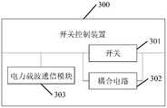
- the switch control device 300 in the embodiment of the present applicationincludes:
- Switch 301coupling circuit 302 and PLC module 303;
- the coupling circuit 302is connected in parallel with both ends of the switch 301;
- the PLC module 303is connected in parallel with one end of the coupling circuit 302, and the PLC module is connected in parallel with the inlet end of the switch 301;
- the switch 301is used to transmit the first PLC signal to the gateway device when it is closed;
- the coupling circuit 302is used to transmit the second PLC signal to the gateway device when the switch 301 is off;
- the PLC module 303is configured to send a third PLC signal to the gateway device, and the third PLC signal includes the first address identifier corresponding to the first switch control device.
- FIG. 4is a schematic diagram of another structure of the switch control device in the embodiment of the application.
- A1, A2, B1, B2, C1, C2are phase wires, and N is a live wire.
- the switchWhen the switch is closed, the PLC signal is transmitted from A1, B1, and C1 to A2, B2, and C2 through the switch.
- the switchWhen the switch is off, the PLC signal is transmitted from A1, B1, and C1 to A2, B2, and C2 through the coupling circuit.
- the power carrier communication moduleis included, that is, the switch control device has a PLC communication function, and the switch can be in the closed or disconnected state to directly send the third PLC signal to the gateway device through the power carrier communication module.
- the example shown in Fig. 4is a scenario where the PLC module is connected in parallel with the inlet end of the switch. In practical applications, the PLC module can also be connected in parallel with the outlet end of the switch.
- the switch control deviceafter the switch control device includes a PLC module, that is, the switch control device has PLC communication function, the switch control device can directly report the power failure information to the gateway device without waiting for the electricity meter to report the power failure information to the gateway device, which can improve the fault Feedback speed.
- the third PLC signalcan include information such as switch status, tripping, power failure, and fault.
- the coupling circuit 202specifically includes a signal transformer and at least 6 safety capacitors;
- At least 6 safety capacitorsare used to select PLC signals of a specific frequency band
- the signal transformeris used to couple the PLC signal.
- FIG. 5is a schematic structural diagram of the coupling circuit in the switch control device in the embodiment of the application.
- the switch control deviceincluding 8 safety capacitors and 2 signal transformers as an example, Describe the switch control device provided by this application.
- C1 to C8are safety capacitors
- T1is the first signal transformer
- T2is the second signal transformer
- A1, A2, B1, B2, C1, C2are phase wires
- Nis the live wire.
- the switch illustrated in FIG. 5is a four-pole switch, and in practical applications, a three-pole switch can also be used, and the connection method is similar to that of a four-pole switch, and will not be repeated here.
- the three-level switchcan operate the no-load circuit within a certain range, and the four-pole switch can improve the electrical safety during electrical maintenance. Therefore, the switches in the switch control device can be different types of switches in different application scenarios. Thereby enhancing the flexibility and selectivity of the scheme.
- the coupling circuitis connected in parallel with the switch, and the safety capacitor C1 is connected to the phase line C1, the safety capacitor C2 is connected to the phase line B1, the safety capacitor C3 is connected to the phase line A1, and the safety capacitor C4 is connected to the phase line C2.
- the safety capacitor C5is connected to the phase line B2
- the safety capacitor C6is connected to the phase line A2
- the safety capacitor C7 and the safety capacitor C8are connected to both ends of the first signal transformer T1 and the second signal transformer T2
- Nis connected with Zero wire copper bar or cable connection.
- the switch contact in the switch control deviceWhen the switch contact in the switch control device is closed, that is, when the switch is in the closed state, the two ends of the coupling circuit are in a short-circuit state, and the PLC signal is transmitted through the switch in the switch control device.
- the switch contact in the switch control deviceis open , That is, when the switch is in the off state, the safety capacitors C1 to C3 will select the PLC signal of a specific frequency band to isolate other signals.
- Other signalscan be power frequency AC signals or other low frequency signals.
- the first signal transformer and the second signal transformer in the coupling circuitwill couple the PLC signal to improve
- the voltage resistance of the incoming wire end and the outgoing wire end when disconnectedimproves the reliability of the coupling circuit, thereby improving the reliability and feasibility of this embodiment.
- Figure 6is a schematic diagram of the flow of the PLC signal in the switch control device in the embodiment of the application.
- the PLC signalpasses through the safety capacitor C1 from the input terminal.
- To C3is coupled to the secondary side of the transformer through the first signal transformer T1, that is, the right side coil of the first signal transformer T1
- the PLC signalis coupled to the secondary side of the second signal transformer T2 through the safety capacitor C7 and the safety capacitor C8, namely
- the right side coil of the second signal transformer T2transmits the PLC signal to the output terminal through the safety capacitor C4 to the safety capacitor C6, completing the transmission of the PLC signal from the input terminal to the output terminal.
- the reverse PLC signalcan also be transmitted from the outlet end to the inlet end through a similar flow direction, and the details will not be repeated here.
- the safety capacitorcan select the PLC signal of a specific frequency band to be transmitted through the coupling circuit, and when it is disconnected, a higher surge voltage will be generated.
- the transformercan couple the PLC signal to improve the coupling circuit Withstand voltage, thereby improving the reliability of the coupling circuit.
- FIG. 7is an architecture of the power distribution network system in the embodiment of the present application.
- the power distribution network systemincludes user meter boxes, branch boxes, power distribution cabinets, gateway equipment, and power transformers, which are used to provide power supply;
- the user meter boxincludes the aforementioned switch control device 200 and an electric meter;
- the branch boxincludes the aforementioned switch control device 200;
- the power distribution cabinetincludes the aforementioned switch control device 200.
- FIG. 8is a flowchart of a method for information transmission in an embodiment of this application. Specifically, FIG. 8 is a method for information transmission based on the distribution network system shown in FIG. 7. The specific method is as follows:
- the switchwhen the switch is open, the first PLC signal is transmitted to the gateway device through the coupling circuit, and when the switch is closed, the second PLC signal is transmitted to the gateway device through the switch.
- the switch A1 in the distribution boxis in the off state
- the switch B1 in the branch boxis in the off state
- the switch C1 in the user meter boxis also in the off state.
- the power meter on the linewill be powered off at this time, and first information will be generated, where the first information can include meter data, power outage event information, trip event information, abnormal event information, user data, message type, and address information , Where the address information includes address information corresponding to switch A1, switch B1, and switch C1. Since switches A1, B1, and C1 are off, the first information generated by the meter cannot be transmitted through switches A1, B1, and C1.
- the meterwhen the meter detects a power failure, it will first randomly delay for a period of time before detecting the channel. If the channel is occupied, that is, it is not idle, it will be randomly delayed for a period of time, and the signal occupancy will be detected again. If the channel is idle, the first PLC signal will be transmitted to the branch box through the coupling circuit in the user meter box , And then the coupling circuit in the branch box transmits the first PLC signal to the power distribution cabinet, and further, the coupling circuit in the power distribution cabinet transmits the first PLC signal to the gateway device, thereby completing the reporting of the first information, where the first PLC The signal includes the first information.
- the switch A1 in the distribution boxis in the closed state
- the switch B1 in the branch boxis in the open state
- the switch C1 in the user meter boxis in the closed state
- the meter on the linewill be powered off, and second information will be generated.
- the second informationmay include meter data, power outage event information, trip event information, abnormal event information, user data, message type, and address information.
- the address informationincludes the address information corresponding to the switch B1.
- the switch B1Since the switch B1 is in the off state, the first information generated by the electric meter cannot be transmitted through the switch B1, so the second PLC signal will be transmitted to the branch box through the switch in the user meter box, and then the coupling circuit in the branch box will be sent to the power distribution
- the cabinettransmits the second PLC signal. Further, the switch in the power distribution cabinet transmits the second PLC signal to the gateway device, thereby completing the reporting of the second information, where the second PLC signal includes the second information.
- the switch control devicetransmits the information included in the PLC signal to the gateway device through different transmission channels when the switch is in different states, thereby improving the reliability and feasibility of the present application.
- FIG. 9is another schematic diagram of the power distribution network system in the embodiment of the application.
- the power distribution network systemincludes user meter boxes, branch boxes, power distribution cabinets, gateway equipment, and power transformers. Used to provide power supply;
- the user meter boxincludes the aforementioned switch control device 300 and an electric meter;
- the branch boxincludes the aforementioned switch control device 300;
- the power distribution cabinetincludes the aforementioned switch control device 300.
- the third PLC signalcan be directly sent to the gateway device through the PLC module in the switch control device, and the third PLC signal includes the first address identifier corresponding to the first switch control device.
- switch A2in the power distribution network system shown in Figure 9, if switch A2 is in the open state, switch B2 in the branch box is in the closed state, and switch C2 in the user meter box is in the closed state.
- the power meter on the linewill be powered off, and the first information will be generated.
- the first informationis similar to the foregoing and will not be repeated here.
- the switch A2generates second information.
- the second informationis data information generated by the switch control device when the switch in the switch control device is in the off state.
- the second informationmay include power outage event information, trip event information, Abnormal event information or message type, and then directly send a third PLC signal to the gateway device through the PLC module after generating the second information.
- the switch control deviceafter the switch control device includes a PLC module, that is, the switch control device has a PLC communication function, the switch control device can directly send the third PLC signal to the gateway device, saving multiple transmission information resources, thereby improving transmission efficiency.
- the switch in the switch control deviceafter the switch is in the off state for a period of time, because there is a backup power unit in the PLC module, it can maintain the working state for a certain period of time after the switch is off. , Thereby improving the reliability and feasibility of this application.
- sending the third PLC signal to the gateway device through the PLC module in the switch control devicemay further include:
- a confirmation message replies from the gateway deviceWhen a confirmation message replies from the gateway device is received, a first reply message is broadcasted, where the confirmation message carries the second address identifier, and the first reply message carries the second address identifier.
- the switch control device including the power carrier communication module in the power distribution network system shown in FIG. 9is taken as a node.
- the nodeis an unpowered node
- the switch in the switch control deviceis in the off state, the node is a power failure node.
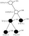
- FIG. 10is a node communication flowchart of the information transmission method in an embodiment of the application, and 10A to 10F in FIG. 10F is the power failure node.
- the information transmission between nodesis not divided by geographic location.
- the signal strengthis used for division. That is, when the unpowered node 10A in FIG. 10 is a gateway device, the unpowered node 10B may be a gateway device.
- the unpowered node 10Bcan be the switch control device existing in switch A1, or the switch control device existing in switch B1.
- the specific transmission between nodesis divided into upper and lower levels This is not limited.
- the non-power-off node 10Bmeans that the switch in the switch control device is in a closed state, and the non-power-off node 10B can receive either the power failure node 10C or the power failure node 10D.
- the first broadcast messagecan be a user datagram protocol (UDP) message and an internet protocol (IP) message, so the first broadcast message includes the link layer header, IPv6 (Internet protocol version 6, the sixth-generation network protocol) header, UDP header, power failure report message payload, and link layer frame check.
- IPv6 headeralso includes the source IPv6 address, destination IPv6 address, and other fields in the IPv6 header.
- the source IPv6 addressis either the power failure node 10C or the power failure node 10D
- the destination IPv6 addressis the broadcast address FF02::1.
- Different PLC technologiescorrespond to different link layer header formats.
- the header formatcan be the link layer message authentication code (MAC) address corresponding to the IPv6 address, or the short address bitmap of the power-off node, because the gateway device will assign a short address to each node when the node enters the network, such as a terminal Identifier (terminal identity document, TEI), the TEI is usually 12 bits, and the link layer header can use the TEI corresponding to the unpowered node 10B and the TEI corresponding to the unpowered node 10A to send the report message.
- the power failure report message payloadcan include the message type, sequence number, starting short address, and the bitmap of the short address of the power failure node.
- the message type of the reported message in the embodiment of the applicationis power failure reporting
- the starting short addressis the minimum short address of the reporting node
- the sequence numberis used to indicate the sequence number of the message
- the first broadcast message received by the node 10B without power failure each timeDifferent sequence numbers should be carried, because the first broadcast message may be forwarded multiple times, and different sequence numbers are carried so that other nodes can remove duplicate messages after receiving the message repeatedly, and the short address bitmap of the outage node is from the outage node
- the current HPLC maximum networking scaleis 1024, which requires a total of 128 bytes , It can also be said that a total of 1024 bits are required, which can represent 1024 nodes.
- the non-power-off node 10Baggregates the second address identifiers in the first broadcast message, where the aggregation method may be to aggregate the first address identifiers through a bitmap or directly aggregate the second address identifiers. It should be noted that, in the embodiments of the present application, examples are made in a bitmap manner, and in actual applications, the manner of aggregate address identification is not limited.
- the unpowered node 10Bmay then send a report message to the unpowered node 10A.
- the report messagemay include the link layer header, the IPv6 header, the UDP header, the power outage report message payload, and the link layer frame check.
- the IPv6 headeralso Including the source IPv6 address, destination IPv6 address, and other fields in the IPv6 header.
- the source IPv6 addressis the address corresponding to the unpowered node 10B
- the destination IPv6 addressis the address corresponding to the unpowered node 10A
- the link layer headerThe TEI corresponding to the unpowered node 10B and the TEI corresponding to the unpowered node 10A may be used to send the report message.
- the load of the power failure report messagecan include the message type, sequence number, starting short address, and the bitmap of the short address of the power failure node.
- the message type of the reported message in the embodiment of the present applicationis power failure report
- the starting short addressis the minimum short address of the reported node
- the sequence numberis used to indicate the sequence number of the message.
- the non-power-off node 10Bwhen the non-power-off node 10B receives the confirmation message from the non-power-off node 10A, it will send a first reply message to either the power-off node 10C or the power-off node 10D.
- the confirmation messageincludes the link layer header, the IPv6 header, the UDP header, the load of the power failure report message, and the link layer frame check.
- the IPv6 headeralso includes the source IPv6 address, the destination IPv6 address, and other fields in the IPv6 header. For node 10A, the source IPv6 address is the address corresponding to the unpowered node 10A, and the destination IPv6 address is the address corresponding to the unpowered node 10B.
- the power outage report message payloadcan include the message type, serial number, initial short address, and power outage node Short address bitmap, where the message type of the confirmation message is power failure confirmation.
- the first reply messageincludes the link layer header, IPv6 header, UDP header, power failure report message payload, and link layer frame check.
- the IPv6 headeralso includes the source IPv6 address, destination IPv6 address, and other fields in the IPv6 header. For node 10A, the source IPv6 address is the address corresponding to node 10B without power failure, and the destination IPv6 address is the broadcast address FF02::1.
- the power failure report message payloadcan include message type, sequence number, start short address, and power failure node short Address bitmap, where the message type of the first reply message is power failure confirmation.
- the switch in the switch control devicewhen the switch in the switch control device is closed, the second broadcast message sent by at least one switch control device can be received, and the report message carrying the first address identifier corresponding to the second broadcast message can be sent to the gateway device, Then send a first reply message carrying at least one first address identifier to at least one switch control device through the confirmation message sent by the gateway, so that at least one switch control device can determine whether to continue sending the second broadcast message according to the first reply message , To reduce repeated reporting of the same information, save bandwidth resources, and improve information transmission efficiency.
- sending the third PLC signal to the gateway device through the PLC module in the switch control devicemay further include:
- the switchWhen the switch is turned off, broadcast a second broadcast message, and the second broadcast message includes the first address identifier corresponding to the first switch control device;
- the second broadcast messageis not sent
- the second broadcast messageis broadcasted.
- the non-power-off node 10Ais the gateway device as an example.
- the power-off node 10Cis the switch in the switch control device in the disconnected state, and then the power-off node 10C can send to the non-power-off node 10B Send a second broadcast message.
- the second broadcast messageincludes the link layer header, IPv6 header, UDP header, power failure report message payload, and link layer frame check.
- the IPv6 headeralso includes the source IPv6 address, destination IPv6 address, and IPv6 header.
- the source IPv6 addressis the address corresponding to the power failure node 10C
- the destination IPv6 addressis the broadcast address FF02::1
- the power failure report message payloadcan include message type, serial number, and initial short address
- the message type of the second broadcast message in the embodiment of the present applicationis power failure report, and the others are similar to the foregoing, and will not be repeated here.
- the outage node 10Bwhen the outage node 10B receives the confirmation message sent by the outage node 10A, it will send a second reply message to either the outage node 10C or the outage node 10D, and after the outage node 10C receives the second reply message, it can According to the second reply message, it is determined whether the second address identifier exists in the short address bitmap of the power failure node in the second reply message. If it exists, the second broadcast message will not be sent to the non-power failure node 10B. If not, it will continue to The non-power-off node 10B sends the second broadcast message, and the second reply message and the second broadcast message are similar to the foregoing, and will not be repeated here.
- the second broadcast informationmay be sent to at least one switch control device, and after the at least one switch control device receives the confirmation message sent by the gateway device, the at least one switch is received
- the control devicesends a second reply message carrying at least one first address identifier, and confirms through the second reply message whether the address identifier corresponding to the data information has been successfully reported to the network device, reducing repeated reporting of the same data information, and saving bandwidth resources, Improve the efficiency of information transmission.
- the information transmission method in the embodiment of the present applicationmay further include:
- the third PLC signalis not sent
- the third PLC signalis broadcasted.
- the power-off node 10C to the power-off node 10Fis the off state of the switch in the switch control device.
- the third broadcast messagesent by either the power outage node 10E or the outage node 10F.
- the third broadcast messagecarries the link layer header, the IPv6 header, the UDP header, the load of the power outage report message, and the link layer frame check.
- the IPv6 headeralso Including the source IPv6 address, destination IPv6 address, and other fields in the IPv6 header.
- the source IPv6 addressis any one of the outage node 10E or the outage node 10F
- the destination IPv6 addressis the broadcast address FF02::1
- the load of the power failure report messagecan include the message type, sequence number, starting short address, and the short address bitmap of the power failure node.
- the message type of the third broadcast messageis power failure report, and the others are similar to the foregoing, here No longer.
- the outage node 10Caggregates the third address identifier corresponding to any one of the outage node 10E or the outage node 10F through a bitmap. Since the second reply message sent by the outage node 10B has been received, the outage node 10C can be based on the second The reply message determines whether the third address identifier corresponding to any one of the power failure node 10E or the power failure node 10F exists in the power failure node short address bitmap in the second reply message, and if it exists, the third PLC signal is not sent to the non-power failure node 10B, If it does not exist, the third PLC signal is sent to the unpowered node 10B.
- the reply messageis similar to the foregoing, so I will not repeat it here.
- the switch control deviceafter the switch control device receives the third broadcast message sent by the third switch control device, it determines whether it needs to be sent by judging whether the third address identifier corresponding to the third switch control device exists in the second reply message.
- the third PLC signalreduces repeated reporting of the same data information, saves bandwidth resources, and improves information transmission efficiency.
- the disclosed system, device, and methodmay be implemented in other ways.
- the device embodiments described aboveare merely illustrative, for example, the division of the units is only a logical function division, and there may be other divisions in actual implementation, for example, multiple units or components may be combined or It can be integrated into another system, or some features can be ignored or not implemented.
- the displayed or discussed mutual coupling or direct coupling or communication connectionmay be indirect coupling or communication connection through some interfaces, devices or units, and may be in electrical, mechanical or other forms.
- the units described as separate componentsmay or may not be physically separated, and the components displayed as units may or may not be physical units, that is, they may be located in one place, or they may be distributed on multiple network units. Some or all of the units may be selected according to actual needs to achieve the objectives of the solutions of the embodiments.
- the functional units in the various embodiments of the present applicationmay be integrated into one processing unit, or each unit may exist alone physically, or two or more units may be integrated into one unit.
- the above-mentioned integrated unitcan be implemented in the form of hardware or software functional unit.
- the integrated unitis implemented in the form of a software functional unit and sold or used as an independent product, it can be stored in a computer readable storage medium.
- the technical solution of the present applicationessentially or the part that contributes to the existing technology or all or part of the technical solution can be embodied in the form of a software product, and the computer software product is stored in a storage medium , Including several instructions to make a computer device (which may be a personal computer, a server, or a network device, etc.) execute all or part of the steps of the methods described in the various embodiments of the present application.
- the aforementioned storage mediainclude: U disk, mobile hard disk, read-only memory (ROM, read-only memory), random access memory (RAM, random access memory), magnetic disks or optical disks and other media that can store program codes. .
Landscapes
- Engineering & Computer Science (AREA)
- Power Engineering (AREA)
- Computer Networks & Wireless Communication (AREA)
- Signal Processing (AREA)
- Cable Transmission Systems, Equalization Of Radio And Reduction Of Echo (AREA)
Abstract
Description
Translated fromChinese本申请要求了2019年11月11日提交的,申请号为201911097619.8,发明名称为“一种PLC网络中信息传输的方法、装置和系统”的中国申请的优先权,其全部内容通过引用结合在本申请中。This application claims the priority of the Chinese application filed on November 11, 2019, the application number is 201911097619.8, and the invention title is "a method, device and system for information transmission in a PLC network", the entire content of which is incorporated by reference In this application.
本申请实施例涉及通信领域,尤其涉及一种电力线通信(power line communication,PLC)网络中信息传输的方法、装置和系统。The embodiments of the present application relate to the field of communications, and in particular to a method, device, and system for information transmission in a power line communication (PLC) network.
随着电力行业市场化改革的深入进行,以及电力物联网的快速发展。当前国家电网正在广泛进行电力物联网的建设,在配电领域,低压设备主动上报停电事件信息已成为国家电网广泛应用于电力物联网建设的一项重要目标。长期以来停电事件由低压设备主动上感知停电并上报的技术,可以帮助供电部门在用户报修之前,先获取停电信息,并利用边缘计算数据分析能力,分析出故障点并恢复供电,提升国家电网的运行与维护的效率。另外,低压设备已经实现智能化改造,且低压设备的通信方式可以为电力线通信(power line communication,PLC)、微功率无线(radio frequency,RF),或,PLC与RF结合而成的双模通信,因此配电网络中本地通信域内中所有开关都会配备通信模块。With the deepening of market reforms in the power industry, as well as the rapid development of the power Internet of Things. Currently, the State Grid is extensively building the Internet of Power Things. In the field of power distribution, low-voltage equipment actively reporting power outage information has become an important goal of the State Grid widely used in the construction of the Internet of Power Things. For a long time, low-voltage equipment actively detects and reports power outages. It can help the power supply department to obtain power outage information before users report for repairs, and use edge computing data analysis capabilities to analyze the point of failure and restore power supply, improving the national grid Efficiency of operation and maintenance. In addition, low-voltage equipment has realized intelligent transformation, and the communication mode of low-voltage equipment can be power line communication (PLC), micro-power wireless (radio frequency, RF), or dual-mode communication formed by the combination of PLC and RF Therefore, all switches in the local communication domain in the power distribution network will be equipped with communication modules.
目前,现有技术中一种停电事件信息传输的方法,在停电情况下采用停电上报技术,具体原理图可参阅图1,当开关A1因为用电过流或漏电导致跳闸时,位于A1开关下方的电表会断电,而图1所示的电表安装有PLC通信模块,即所有受到A1开关跳闸影响的电表会通过PLC通信模块向网关上报停电事件信息,然后网关根据上报的停电事件信息确定停电面积以及故障点位置等。At present, a method for transmitting power outage event information in the prior art adopts the power outage reporting technology in the case of a power outage. The specific schematic diagram can be seen in Figure 1. When the switch A1 trips due to overcurrent or leakage, it is located below the A1 switch The meter will be powered off, and the meter shown in Figure 1 is equipped with a PLC communication module, that is, all meters affected by the A1 switch tripping will report the power outage event information to the gateway through the PLC communication module, and then the gateway will determine the power outage based on the reported power outage event information Area and location of failure points, etc.
然而,现有技术中停电事件信息上报的方法会导致如下缺陷,当用户负载短路或过载引起A1开关分断时,与A1同线路的其他开关设备,例如B1和C1,这些开关设备若出现分断,所生成的停电事件信息无法向网关传输,使得电表无法通过PLC通信方式B1和C1对应的停电事件信息上报到网关。However, the method of reporting power outage event information in the prior art will cause the following defects. When the user load is short-circuited or overloaded and the A1 switch is disconnected, other switch devices on the same line as A1, such as B1 and C1, if these switch devices are disconnected, The generated power failure event information cannot be transmitted to the gateway, so that the electricity meter cannot report the power failure event information corresponding to the PLC communication methods B1 and C1 to the gateway.
发明内容Summary of the invention
本申请提供了一种PLC网络中信息传输的方法、装置和系统,在开关断开时,也能够向网关设备发送PLC信号,并向网关设备上报停电、跳闸等信息。This application provides a method, device and system for information transmission in a PLC network. When the switch is off, it can also send a PLC signal to the gateway device and report information such as power outages and trips to the gateway device.
第一方面,本申请提供一种开关控制装置,包括:开关以及耦合电路,耦合电路与开关两端并联。耦合电路用于在开关断开时,向网关设备传输第一PLC信号。In a first aspect, the present application provides a switch control device, including: a switch and a coupling circuit, and the coupling circuit is connected in parallel with both ends of the switch. The coupling circuit is used to transmit the first PLC signal to the gateway device when the switch is off.
开关断开时,可能是所述开关控制装置发生了跳闸、停电等事件。此时,所述开关控制装置就可以通过耦合电路将下面接入的电表或其他装置的PLC模块发送的第一PLC信号传输给网关设备。第一PLC信号中可以包括跳闸、停电、故障等信息,还可以包括电表数据,日志等信息。When the switch is off, it may be that the switch control device has tripped, power outage and other events. At this time, the switch control device can transmit the first PLC signal sent by the PLC module of the meter or other device connected below to the gateway device through the coupling circuit. The first PLC signal may include information such as trips, power failures, and faults, as well as information such as electricity meter data and logs.
结合第一方面,在第一方面的第一种实现方式中,开关用于在闭合时向网关设备传输第 二PLC信号。With reference to the first aspect, in the first implementation of the first aspect, the switch is used to transmit the second PLC signal to the gateway device when it is closed.
开关闭合时,存在两种可能:一种可能是,PLC网络中的电表和装置均正常工作,第二PLC信号通过开关正常传输给网关设备。此时第二PLC信号中一般携带电表数据、日志等信息。另一种可能是,所述开关控制装置下面接入的电表或其他装置发生了停电、跳闸等事件,第二PLC信号中包括跳闸、停电、故障等信息,还可以包括电表数据,日志等信息。When the switch is closed, there are two possibilities: One possibility is that the meters and devices in the PLC network are all working normally, and the second PLC signal is normally transmitted to the gateway device through the switch. At this time, the second PLC signal generally carries information such as electricity meter data and logs. Another possibility is that the power meter or other devices connected under the switch control device have events such as power outages, trips, etc., and the second PLC signal includes information such as trips, power outages, faults, etc., and may also include meter data, logs and other information .
本申请提供的开关控制装置通过设置与开关并联的耦合电路,可以在开关处于断开或者闭合时,通过不同的传输通道向网关设备发送PLC信号,以传输PLC信号所携带的各种信息,提升PLC网络通信的可靠性。The switch control device provided by the present application is provided with a coupling circuit connected in parallel with the switch, and when the switch is open or closed, it can send PLC signals to the gateway device through different transmission channels to transmit various information carried by the PLC signals. The reliability of PLC network communication.
结合第一方面或第一方面的第一种实现方式中,在第一方面的第二种实现方式中,开关控制装置还包括PLC模块,PLC模块与耦合电路一端并联,且PLC模块与开关一端并联。PLC模块用于向网关设备发送第三PLC信号。In combination with the first aspect or the first implementation manner of the first aspect, in the second implementation manner of the first aspect, the switch control device further includes a PLC module, the PLC module is connected in parallel with one end of the coupling circuit, and the PLC module is connected to one end of the switch in parallel. The PLC module is used to send the third PLC signal to the gateway device.
开关控制装置包括PLC模块后,所述开关控制装置具备了PLC通信功能。一旦所述开关控制装置发生故障、停电或跳闸等事件,所述开关控制装置可以及时向网关设备发送第三PLC信号,提升通信效率。此时第三PLC信号中可以包括开关状态、跳闸、停电、故障等信息。After the switch control device includes a PLC module, the switch control device has a PLC communication function. Once the switch control device has a fault, power outage or trip, the switch control device can send a third PLC signal to the gateway device in time to improve communication efficiency. At this time, the third PLC signal may include information such as switch status, tripping, power failure, and fault.
结合第一方面以及第一方面的第一种和第二种实现方式中任意一种,在第一方面的第三种实现方式中,耦合电路包括信号变压器以及至少6个安规电容,所述至少6个安规电容用于选择特定频段的PLC信号,而信号变压器则用于对选择出的PLC信号进行耦合。Combining the first aspect and any one of the first and second implementation manners of the first aspect, in a third implementation manner of the first aspect, the coupling circuit includes a signal transformer and at least 6 safety capacitors, the At least 6 safety capacitors are used to select the PLC signal of a specific frequency band, and the signal transformer is used to couple the selected PLC signal.
在开关控制装置中的开关断开时,所述至少6个安规电容可以选择特定频段的PLC信号,但是在开关断开时会产生较高浪涌电压,因此通过信号变压器对选择出的PLC信号进行耦合,可以提升耦合电路的耐压性,从而提升耦合电路的可靠性。When the switch in the switch control device is turned off, the at least 6 safety capacitors can select the PLC signal of a specific frequency band, but a higher surge voltage will be generated when the switch is turned off, so the selected PLC is paired by the signal transformer The signal coupling can improve the withstand voltage of the coupling circuit, thereby improving the reliability of the coupling circuit.
第二方面,本申请提供一种信息传输的方法,应用于第一开关控制装置,第一开关控制装置包括开关以及耦合电路,耦合电路与开关两端并联,包括:In a second aspect, the present application provides a method of information transmission, which is applied to a first switch control device. The first switch control device includes a switch and a coupling circuit. The coupling circuit is connected in parallel with both ends of the switch and includes:
当开关断开时,通过耦合电路向网关设备传输第一PLC信号。When the switch is off, the first PLC signal is transmitted to the gateway device through the coupling circuit.
结合第二方面,在第二方面的第一种实现方式中,当开关闭合时,通过开关向网关设备传输第二PLC信号。With reference to the second aspect, in the first implementation manner of the second aspect, when the switch is closed, the second PLC signal is transmitted to the gateway device through the switch.
开关断开时,可能是所述第一开关控制装置发生了跳闸、停电等事件。此时,所述第一开关控制装置就可以通过耦合电路将下面接入的电表或其他装置的PLC模块发送的第一PLC信号传输给网关设备。第一PLC信号中可以包括跳闸、停电、故障等信息,还可以包括电表数据,日志等信息。When the switch is off, it may be that the first switch control device has tripped, power outage and other events. At this time, the first switch control device can transmit the first PLC signal sent by the PLC module of the meter or other device connected below to the gateway device through the coupling circuit. The first PLC signal may include information such as trips, power failures, and faults, as well as information such as electricity meter data and logs.
开关闭合时,存在两种可能:一种可能是,PLC网络中的电表和装置均正常工作,第二PLC信号通过开关正常传输给网关设备。此时第二PLC信号中一般携带电表数据、日志等信息。另一种可能是,所述开关控制装置下面接入的电表或其他装置发生了停电、跳闸等事件,第二PLC信号中包括跳闸、停电、故障等信息,还可以包括电表数据,日志等信息。When the switch is closed, there are two possibilities: One possibility is that the meters and devices in the PLC network are all working normally, and the second PLC signal is normally transmitted to the gateway device through the switch. At this time, the second PLC signal generally carries information such as electricity meter data and logs. Another possibility is that the power meter or other devices connected under the switch control device have events such as power outages, trips, etc., and the second PLC signal includes information such as trips, power outages, faults, etc., and may also include meter data, logs and other information .
本申请提供的信息传输的方法,在开关处于断开或者闭合时,可以通过不同的传输通道向网关设备发送PLC信号,以传输PLC信号所携带的各种信息,提升PLC网络通信的可靠性。In the information transmission method provided in this application, when the switch is open or closed, PLC signals can be sent to the gateway device through different transmission channels to transmit various information carried by the PLC signals and improve the reliability of PLC network communication.
结合第二方面或第二方面的第一种实现方式中任意一种,在第一方面的第二种实现方式中,应用于第二开关控制装置,第二开关控制装置包括PLC模块,PLC模块与耦合电路一端并联,且PLC模块与开关一端并联,信息传输的方法还包括:In combination with the second aspect or any one of the first implementation manners of the second aspect, in the second implementation manner of the first aspect, it is applied to a second switch control device, the second switch control device includes a PLC module, and a PLC module It is connected in parallel with one end of the coupling circuit, and the PLC module is connected in parallel with one end of the switch. The information transmission method further includes:
通过PLC模块向向网关设备发送第三PLC信号,第三PLC信号中包括第一开关控制装置对应的第一地址标识。The third PLC signal is sent to the gateway device through the PLC module, and the third PLC signal includes the first address identifier corresponding to the first switch control device.
开关控制装置包括PLC模块后,即开关控制装置有PLC通信功能,一旦所述开关控制装 置发生故障、停电或跳闸等事件,所述开关控制装置可以及时向网关设备发送第三PLC信号,提升通信效率。此时第三PLC信号中可以包括开关状态、跳闸、停电、故障等信息。After the switch control device includes the PLC module, that is, the switch control device has PLC communication function. Once the switch control device fails, power outage or trip and other events, the switch control device can send a third PLC signal to the gateway device in time to improve communication effectiveness. At this time, the third PLC signal may include information such as switch status, tripping, power failure, and fault.
结合第二方面的第二种实现方式,在第二方面的第三种实现方式中,可以接收第二开关控制装置广播发送的第一广播消息,第一广播消息中包括停电信息,然后向网关设备单播发送上报消息,其中,上报消息携带第二开关控制装置对应的第二地址标识,当接收到网关设备回复的确认消息时,广播发送第一回复消息,其中的确认消息携带第二地址标识,第一回复消息携带第二地址标识。In combination with the second implementation manner of the second aspect, in the third implementation manner of the second aspect, the first broadcast message broadcasted by the second switch control device can be received, and the first broadcast message includes the power failure information, and then the information is sent to the gateway The device unicasts a report message, where the report message carries the second address identifier corresponding to the second switch control device, and when a confirmation message replies from the gateway device is received, it broadcasts the first reply message, where the confirmation message carries the second address ID, the first reply message carries the second address ID.
接收第二开关控制装置广播发送的包括停电信息的第一广播消息,并向网关设备网关设备单播发送携带有第二地址标识的上报消息,然后通过网关设备回复的确认消息第二开关控制装置广播发送第一回复消息,使得至少一个开关控制装置可以根据该第一回复消息判断是否还需继续广播包括停电信息的第一广播消息,减少相同的停电信息重复上报,节省带宽资源,提升信息传输效率。Receives the first broadcast message including the power outage information broadcasted by the second switch control device, and unicasts the report message carrying the second address identifier to the gateway device gateway device, and then sends the confirmation message back through the gateway device. The second switch control device Broadcast the first reply message so that at least one switch control device can determine whether to continue broadcasting the first broadcast message including power outage information according to the first reply message, reducing repeated reporting of the same power outage information, saving bandwidth resources, and improving information transmission effectiveness.
结合第二方面的第三种实现方式,在第二方面的第四种实现方式中,当开关断开时,广播发送第二广播消息,第二广播消息中包括第一地址标识,然后接收第三开关控制装置广播发送的第二回复消息,若第二回复消息中存在第二地址标识,则不再发送第二广播消息,若第二回复消息中不存在第二地址标识,则广播发送第二广播消息。In combination with the third implementation manner of the second aspect, in the fourth implementation manner of the second aspect, when the switch is turned off, a second broadcast message is broadcasted. The second broadcast message includes the first address identifier, and then the second broadcast message is received. The second reply message broadcasted by the three-switch control device, if the second address identifier exists in the second reply message, the second broadcast message is no longer sent, and if the second address identifier does not exist in the second reply message, the second broadcast message is sent by broadcast 2. Broadcast messages.
当开关控制装置中的开关断开时,可以向网关设备广播发送第二广播消息,并接收第二回复消息,然后通过第二回复消息判断是否还需要继续发送第二广播消息,减少相同信息重复上报,节省带宽资源,提升信息传输效率。When the switch in the switch control device is turned off, the second broadcast message can be broadcast to the gateway device, and the second reply message can be received, and then the second reply message is used to determine whether it is necessary to continue to send the second broadcast message, reducing the duplication of the same information Reporting saves bandwidth resources and improves information transmission efficiency.
结合第二方面的第四种实现方式,在第二方面的第五种实现方式中,在接收第三开关控制装置广播发送的第二回复消息之后,本申请信息传输的方法还包括:With reference to the fourth implementation manner of the second aspect, in the fifth implementation manner of the second aspect, after receiving the second reply message broadcasted by the third switch control device, the information transmission method of the present application further includes:
首先接收第三开关控制装置发送的第三广播消息,且第三广播消息包括第三开关控制装置对应的第三地址标识,若所接收到第二回复消息中存在第三地址标识,则不再发送第三PLC信号,若所接收到第二回复消息中不存在第三地址标识,则广播发送第三PLC信号。First, receive the third broadcast message sent by the third switch control device, and the third broadcast message includes the third address identifier corresponding to the third switch control device. If the third address identifier exists in the received second reply message, no more The third PLC signal is sent, and if the third address identifier does not exist in the received second reply message, the third PLC signal is broadcasted.
开关控制装置可以通过判断第二回复消息是否存在第三开关控制装置对应的第三地址标识,确定是否需要发送第三PLC信号,减少相同的信息重复上报,节省带宽资源,提升信息传输效率。The switch control device can determine whether a third PLC signal needs to be sent by determining whether the second reply message has a third address identifier corresponding to the third switch control device, so as to reduce repeated reporting of the same information, save bandwidth resources, and improve information transmission efficiency.
第三方面,本申请提供一种配电网络系统,包括:In the third aspect, this application provides a power distribution network system, including:
用户表箱、分支箱、配电柜、网关设备以及电力变压器,电力变压器用于提供电力供应;User meter boxes, branch boxes, power distribution cabinets, gateway equipment and power transformers, which are used to provide power supply;
用户表箱包括如第一方面至第一方面的第三种实现方式中任一项的开关控制装置以及电表;The user meter box includes the switch control device and the electric meter as in any one of the first aspect to the third implementation manner of the first aspect;
分支箱包括如第一方面至第一方面的第三种实现方式中任一项的开关控制装置;The branch box includes the switch control device of any one of the first aspect to the third implementation manner of the first aspect;
配电柜包括如第一方面至第一方面的第三种实现方式中任一项的开关控制装置。The power distribution cabinet includes the switch control device of any one of the first aspect to the third implementation manner of the first aspect.
本申请提供的开关控制装置中,当开关处于断开状态时,通过开关控制装置中的耦合电路向网关设备传输第一PLC信号,开关控制装置中的开关处于闭合状态时,通过开关控制装置中的开关向网关设备传输第二PLC信号,其中PLC信号均携带数据信息,使得在开关处于不同状态时能够传输数据信息。In the switch control device provided by the present application, when the switch is in the open state, the first PLC signal is transmitted to the gateway device through the coupling circuit in the switch control device, and when the switch in the switch control device is in the closed state, the switch control device The switch transmits the second PLC signal to the gateway device, where the PLC signals all carry data information, so that the data information can be transmitted when the switch is in a different state.
另外,本申请的配电网络系统中,当配电网络系统出现故障时,即开关断开时,携带有停电、跳闸或者故障等信息的第一PLC信号可以通过开关控制装置中的耦合电路中进行传输,使得第一PLC信号能通过PLC方式发送至网关设备,从而提升信息传输的可靠性。In addition, in the distribution network system of the present application, when the distribution network system fails, that is, when the switch is disconnected, the first PLC signal carrying information such as power outage, trip, or failure can pass through the coupling circuit in the switch control device The transmission is performed so that the first PLC signal can be sent to the gateway device in a PLC manner, thereby improving the reliability of information transmission.
图1为现有技术中配电网络系统的架构示意图;Figure 1 is a schematic diagram of the architecture of a power distribution network system in the prior art;
图2为本申请实施例中开关控制装置的一种结构示意图;2 is a schematic diagram of a structure of a switch control device in an embodiment of the application;
图3为本申请实施例中开关控制装置的另一种结构示意图;3 is a schematic diagram of another structure of the switch control device in an embodiment of the application;
图4为本申请实施例中开关控制装置的又一种结构示意图;4 is a schematic diagram of another structure of the switch control device in an embodiment of the application;
图5为本申请实施例中开关控制装置中耦合电路的结构示意图;5 is a schematic structural diagram of a coupling circuit in a switch control device in an embodiment of the application;
图6为本申请实施例中开关控制装置中PLC信号的流向示意图;6 is a schematic diagram of the flow of PLC signals in the switch control device in an embodiment of the application;
图7为本申请实施例中配电网络系统的一种架构示意图;FIG. 7 is a schematic diagram of an architecture of a power distribution network system in an embodiment of the application;
图8为本申请实施例中信息传输的方法的一种流程示意图;FIG. 8 is a schematic flowchart of a method for information transmission in an embodiment of this application;
图9为本申请实施例中配电网络系统的另一架构示意图;FIG. 9 is a schematic diagram of another architecture of a power distribution network system in an embodiment of the application;
图10为本申请实施例中信息传输的方法的节点通信流程图。Figure 10 is a node communication flow chart of the method for information transmission in an embodiment of the application.
本申请实施例提供了一种信息传输的方法、开关控制装置以及相关系统,用于在在开关断开时,向网关设备发送第一PLC信号,并传输第一PLC信号所携带的数据信息。The embodiments of the present application provide an information transmission method, a switch control device, and a related system, which are used to send a first PLC signal to a gateway device when the switch is off, and transmit data information carried by the first PLC signal.
下面对本申请实施例提供的开关控制装置进行描述,请参阅图2,图2为本申请实施例中开关控制装置的一种结构示意图,本申请实施例中开关控制装置200包括:The following describes the switch control device provided by the embodiment of the present application. Please refer to FIG. 2. FIG. 2 is a schematic structural diagram of the switch control device in the embodiment of the present application. The
开关201以及耦合电路202;
耦合电路202与开关201两端并联;The
开关201,用于在开关201闭合时,向网关设备传输第一电力线通信PLC信号;The
耦合电路202,用于在开关201断开时,向网关设备传输第二PLC信号。The
本申请实施例中,耦合电路为PLC耦合电路,需要说明的是,在实际应用中,也可以为对执行相同功能的耦合电路以其他名称代替,本申请实施例不做限定。其次,网关设备可以为智能配变终端(transformer terminal unit,TTU)或者数据集中器单元(data concentrator unit,DCU)。In the embodiments of the present application, the coupling circuit is a PLC coupling circuit. It should be noted that in practical applications, the coupling circuit that performs the same function can also be replaced by other names, which is not limited in the embodiments of the present application. Secondly, the gateway device may be a smart distribution terminal unit (TTU) or a data concentrator unit (DCU).
可以理解的是,在实际应用中,开关201断开时,常常是因为用电过流或漏电导致开关跳闸,开关虽不跳闸但线路停电,断开状态即为开关无法通过电流或数据信息的状态,本申请实施例不做限定。It is understandable that in practical applications, when the
进一步地,开关闭合时,存在两种可能:一种可能是,PLC网络中的电表和装置均正常工作,第二PLC信号通过开关正常传输给网关设备。此时第二PLC信号中一般携带电表数据、日志等信息。另一种可能是,所述开关控制装置下面接入的电表或其他装置发生了停电、跳闸等事件,第二PLC信号中包括跳闸、停电、故障等信息,还可以包括电表数据,日志等信息。Further, when the switch is closed, there are two possibilities: One possibility is that the electric meters and devices in the PLC network work normally, and the second PLC signal is normally transmitted to the gateway device through the switch. At this time, the second PLC signal generally carries information such as electricity meter data and logs. Another possibility is that the power meter or other devices connected under the switch control device have events such as power outages, trips, etc., and the second PLC signal includes information such as trips, power outages, faults, etc., and may also include meter data, logs and other information .
本申请实施例中,开关控制装置中的开关断开时,可以通过耦合电路构建的传输通道向网关设备传输PLC信号,此外,耦合电路占用体积较小,集成成本较低,还能够提升供电系统的可靠性。In the embodiment of the present application, when the switch in the switch control device is turned off, the PLC signal can be transmitted to the gateway device through the transmission channel constructed by the coupling circuit. In addition, the coupling circuit occupies a small volume, has a low integration cost, and can also improve the power supply system. Reliability.
可选地,图3为本申请实施例中开关控制装置的另一种结构示意图,本申请实施例中开关控制装置300包括:Optionally, FIG. 3 is a schematic diagram of another structure of the switch control device in the embodiment of the present application. The
开关301,耦合电路302和PLC模块303;
耦合电路302与开关301两端并联;The
PLC模块303与耦合电路302一端并联,且PLC模块与开关301的进线端并联;The
开关301,用于在闭合时,向网关设备传输第一PLC信号;The
耦合电路302,用于在开关301断开时,向网关设备传输第二PLC信号;The
PLC模块303,用于向网关设备发送第三PLC信号,第三PLC信号中包括第一开关控制装置对应的第一地址标识。The
具体地,请参阅图4,图4为本申请实施例中开关控制装置的又一种结构示意图,A1、A2、B1、B2、C1、C2为相线,N为火线。在开关闭合时,PLC信号从A1、B1以及C1通过开关向传输A2、B2以及C2,在开关断开时,PLC信号从A1、B1以及C1通过耦合电路向传输A2、B2以及C2。其次,由于包含电力载波通信模块,即开关控制装置具有PLC通信功能,开关处于闭合,或,断开状态均可以通过电力载波通信模块直接向网关设备发送第三PLC信号。可以理解的是,图4示例的为PLC模块与开关的进线端并联的场景,在实际应用中,PLC模块还可以与开关的出线端并联。Specifically, please refer to FIG. 4, which is a schematic diagram of another structure of the switch control device in the embodiment of the application. A1, A2, B1, B2, C1, C2 are phase wires, and N is a live wire. When the switch is closed, the PLC signal is transmitted from A1, B1, and C1 to A2, B2, and C2 through the switch. When the switch is off, the PLC signal is transmitted from A1, B1, and C1 to A2, B2, and C2 through the coupling circuit. Secondly, because the power carrier communication module is included, that is, the switch control device has a PLC communication function, and the switch can be in the closed or disconnected state to directly send the third PLC signal to the gateway device through the power carrier communication module. It can be understood that the example shown in Fig. 4 is a scenario where the PLC module is connected in parallel with the inlet end of the switch. In practical applications, the PLC module can also be connected in parallel with the outlet end of the switch.
本申请实施例中,开关控制装置包括PLC模块后,即开关控制装置有PLC通信功能,可以直接由开关控制装置直接向网关设备上报停电信息,无需等待电表向网关设备上报停电信息,可以提升故障反馈速度,此时第三PLC信号中可以包括开关状态、跳闸、停电、故障等信息。In the embodiment of this application, after the switch control device includes a PLC module, that is, the switch control device has PLC communication function, the switch control device can directly report the power failure information to the gateway device without waiting for the electricity meter to report the power failure information to the gateway device, which can improve the fault Feedback speed. At this time, the third PLC signal can include information such as switch status, tripping, power failure, and fault.
可选地,耦合电路202具体包括信号变压器以及至少6个安规电容;Optionally, the
至少6个安规电容用于选择特定频段的PLC信号;At least 6 safety capacitors are used to select PLC signals of a specific frequency band;
信号变压器用于对PLC信号进行耦合。The signal transformer is used to couple the PLC signal.
具体地,请参阅图5,图5为本申请实施例中开关控制装置中耦合电路的结构示意图,如图6所示,以耦合电路中包括8个安规电容和2个信号变压器为例,说明本申请提供的开关控制装置。其中,C1至C8为安规电容,T1为第一信号变压器,T2为第二信号变压器,A1、A2、B1、B2、C1、C2为相线,而N则为火线。可以理解的是,图5示例的开关为四极开关,而在实际应用中,还可以使用三极开关,连接方式与四级开关类似,在此不做赘述。具体地,三级开关可以进行一定范围内空载线路的操作,而四极开关可以提高电气检修时的电气安全性,因此开关控制装置中的开关可以在不同应用场景下为不同类型的开关,从而提升了本方案的灵活性以及可选择性。Specifically, please refer to FIG. 5. FIG. 5 is a schematic structural diagram of the coupling circuit in the switch control device in the embodiment of the application. As shown in FIG. 6, taking the coupling circuit including 8 safety capacitors and 2 signal transformers as an example, Describe the switch control device provided by this application. Among them, C1 to C8 are safety capacitors, T1 is the first signal transformer, T2 is the second signal transformer, A1, A2, B1, B2, C1, C2 are phase wires, and N is the live wire. It can be understood that the switch illustrated in FIG. 5 is a four-pole switch, and in practical applications, a three-pole switch can also be used, and the connection method is similar to that of a four-pole switch, and will not be repeated here. Specifically, the three-level switch can operate the no-load circuit within a certain range, and the four-pole switch can improve the electrical safety during electrical maintenance. Therefore, the switches in the switch control device can be different types of switches in different application scenarios. Thereby enhancing the flexibility and selectivity of the scheme.
进一步地,耦合电路与开关并联,且安规电容C1与相线C1连接,安规电容C2与相线B1连接,安规电容C3与相线A1连接,安规电容C4与相线C2连接,安规电容C5与相线B2连接,安规电容C6与相线A2连接,安规电容C7和安规电容C8与第一信号变压器T1和第二信号变压器T2的两端连接,而N则与零线铜排或线缆连接。当开关控制装置中开关触点闭合时,即开关处于闭合状态时,耦合电路两端为短路状态,PLC信号通过开关控制装置中的开关进行传输,然而当开关控制装置中开关触点断开时,即开关处于断开状态时,安规电容C1至C3将会选择特定频段的PLC信号,隔离其他信号,其他信号可以为工频交流信号或其他低频信号。而开关断开时会使得耦合电路中的在进线端以及出线端会产生较高的浪涌电压,这时耦合电路中的第一信号变压器以及第二信号变压器将对PLC信号进行耦合,提升断开时进线端以及出线端的耐压性,提升耦合电路的可靠性,从而提升本实施例的可靠性以及可行性。Further, the coupling circuit is connected in parallel with the switch, and the safety capacitor C1 is connected to the phase line C1, the safety capacitor C2 is connected to the phase line B1, the safety capacitor C3 is connected to the phase line A1, and the safety capacitor C4 is connected to the phase line C2. The safety capacitor C5 is connected to the phase line B2, the safety capacitor C6 is connected to the phase line A2, the safety capacitor C7 and the safety capacitor C8 are connected to both ends of the first signal transformer T1 and the second signal transformer T2, and N is connected with Zero wire copper bar or cable connection. When the switch contact in the switch control device is closed, that is, when the switch is in the closed state, the two ends of the coupling circuit are in a short-circuit state, and the PLC signal is transmitted through the switch in the switch control device. However, when the switch contact in the switch control device is open , That is, when the switch is in the off state, the safety capacitors C1 to C3 will select the PLC signal of a specific frequency band to isolate other signals. Other signals can be power frequency AC signals or other low frequency signals. When the switch is turned off, a higher surge voltage will be generated at the incoming and outgoing ends of the coupling circuit. At this time, the first signal transformer and the second signal transformer in the coupling circuit will couple the PLC signal to improve The voltage resistance of the incoming wire end and the outgoing wire end when disconnected improves the reliability of the coupling circuit, thereby improving the reliability and feasibility of this embodiment.
再进一步地,请参阅图6,图6为本申请实施例中开关控制装置中PLC信号的流向示意图,如图6所示,当开关断开时,PLC信号从进线端经过安规电容C1至C3通过第一信号变压器T1耦合到变压器次级侧,即第一信号变压器T1右侧线圈,然后PLC信号经过安规电容C7以及安规电容C8耦合到第二信号变压器T2次级侧,即第二信号变压器T2右侧线圈,经过安规电容C4至安规电容C6将PLC信号传递至出线端,完成PLC信号从进线端到出线端的 传输。可以理解的是,反向的PLC信号也可以从出线端经过类似的流向完成从出线端到进线端的传输,具体此处不再赘述。Still further, please refer to Figure 6. Figure 6 is a schematic diagram of the flow of the PLC signal in the switch control device in the embodiment of the application. As shown in Figure 6, when the switch is turned off, the PLC signal passes through the safety capacitor C1 from the input terminal. To C3 is coupled to the secondary side of the transformer through the first signal transformer T1, that is, the right side coil of the first signal transformer T1, and then the PLC signal is coupled to the secondary side of the second signal transformer T2 through the safety capacitor C7 and the safety capacitor C8, namely The right side coil of the second signal transformer T2 transmits the PLC signal to the output terminal through the safety capacitor C4 to the safety capacitor C6, completing the transmission of the PLC signal from the input terminal to the output terminal. It can be understood that the reverse PLC signal can also be transmitted from the outlet end to the inlet end through a similar flow direction, and the details will not be repeated here.
在开关控制装置中的开关断开时,安规电容可以选择特定频段的PLC信号通过耦合电路传输,而在断开时会产生较高浪涌电压,变压器可以对PLC信号进行耦合,提升耦合电路的耐压性,从而提升耦合电路的可靠性。When the switch in the switch control device is disconnected, the safety capacitor can select the PLC signal of a specific frequency band to be transmitted through the coupling circuit, and when it is disconnected, a higher surge voltage will be generated. The transformer can couple the PLC signal to improve the coupling circuit Withstand voltage, thereby improving the reliability of the coupling circuit.
上面对本申请实施例中的开关控制装置进行了描述,下面对本申请实施例中的配电网络系统进行描述,具体请参阅图7,图7为本申请实施例中配电网络系统的一种架构示意图,配电网络系统包括用户表箱、分支箱、配电柜、网关设备以及电力变压器,电力变压器用于提供电力供应;The switch control device in the embodiment of the present application is described above, and the power distribution network system in the embodiment of the present application is described below. For details, please refer to FIG. 7, which is an architecture of the power distribution network system in the embodiment of the present application. In the schematic diagram, the power distribution network system includes user meter boxes, branch boxes, power distribution cabinets, gateway equipment, and power transformers, which are used to provide power supply;
用户表箱包括前述开关控制装置200以及电表;The user meter box includes the aforementioned
分支箱包括前述开关控制装置200;The branch box includes the aforementioned
配电柜包括前述开关控制装置200。The power distribution cabinet includes the aforementioned
为了便于理解,请参阅8,图8为本申请实施例中信息传输的方法的一种流程示意图,具体地,图8为基于图7所示的配电网络系统中的信息传输的方法。具体方法如下:For ease of understanding, please refer to 8. FIG. 8 is a flowchart of a method for information transmission in an embodiment of this application. Specifically, FIG. 8 is a method for information transmission based on the distribution network system shown in FIG. 7. The specific method is as follows:
801、当开关控制装置中的开关闭合时,通过开关向网关设备传输第二PLC信号。801. When the switch in the switch control device is closed, transmit the second PLC signal to the gateway device through the switch.
802、当开关控制装置中的开关断开时,通过开关控制装置中的耦合电路向网关设备传输第一PLC信号。802. When the switch in the switch control device is turned off, transmit the first PLC signal to the gateway device through the coupling circuit in the switch control device.
本申请实施例中,开关断开时,第一PLC信号通过耦合电路向网关设备传输,而开关闭合时,第二PLC信号通过开关向网关设备传输。In the embodiment of the present application, when the switch is open, the first PLC signal is transmitted to the gateway device through the coupling circuit, and when the switch is closed, the second PLC signal is transmitted to the gateway device through the switch.
示例性地,如图7所示的配电网络系统中,若配电箱中开关A1处于断开状态,分支箱中的开关B1处于断开状态,且用户表箱中的开关C1也处于断开状态,此时处于该线路上的电表会断电,并且生成第一信息,其中第一信息可以包括电表数据、停电事件信息、跳闸事件信息、异常事件信息、用户数据、消息类型以及地址信息,其中地址信息包括开关A1、开关B1以及开关C1对应的地址信息。由于开关A1、B1以及C1已为断开状态,电表所生成的第一信息无法通过开关A1、B1以及C1进行传输,因此当电表探测到停电事件后,首先将随机延迟一段时间,再检测信道的占用情况,若信道被占用,即处于不空闲的状态,则随机延迟一段时间,并再次检测信号占用情况,若信道空闲则会通过用户表箱中的耦合电路向分支箱传输第一PLC信号,然后分支箱中的耦合电路向配电柜传输第一PLC信号,进一步地,配电柜中的耦合电路向网关设备传输第一PLC信号,由此完成第一信息的上报,其中第一PLC信号中包括有第一信息。Exemplarily, in the power distribution network system shown in FIG. 7, if the switch A1 in the distribution box is in the off state, the switch B1 in the branch box is in the off state, and the switch C1 in the user meter box is also in the off state. On state, the power meter on the line will be powered off at this time, and first information will be generated, where the first information can include meter data, power outage event information, trip event information, abnormal event information, user data, message type, and address information , Where the address information includes address information corresponding to switch A1, switch B1, and switch C1. Since switches A1, B1, and C1 are off, the first information generated by the meter cannot be transmitted through switches A1, B1, and C1. Therefore, when the meter detects a power failure, it will first randomly delay for a period of time before detecting the channel. If the channel is occupied, that is, it is not idle, it will be randomly delayed for a period of time, and the signal occupancy will be detected again. If the channel is idle, the first PLC signal will be transmitted to the branch box through the coupling circuit in the user meter box , And then the coupling circuit in the branch box transmits the first PLC signal to the power distribution cabinet, and further, the coupling circuit in the power distribution cabinet transmits the first PLC signal to the gateway device, thereby completing the reporting of the first information, where the first PLC The signal includes the first information.
示例性地,如图7所示的配电网络系统中,若配电箱中开关A1处于闭合状态,分支箱中的开关B1处于断开状态,且用户表箱中的开关C1处于闭合状态,此时处于该线路上的电表会断电,并且生成第二信息,此时第二信息可以包括电表数据、停电事件信息、跳闸事件信息、异常事件信息、用户数据、消息类型以及地址信息,其中地址信息包括开关B1对应的地址信息。由于开关B1处于断开状态,电表所生成的第一信息无法通过开关B1进行传输,因此会通过用户表箱中的开关向分支箱传输第二PLC信号,然后分支箱中的耦合电路向配电柜传输第二PLC信号,进一步地,配电柜中的开关向网关设备传输第二PLC信号,由此完成第二信息的上报,其中第二PLC信号中包括有第二信息。Exemplarily, in the power distribution network system shown in FIG. 7, if the switch A1 in the distribution box is in the closed state, the switch B1 in the branch box is in the open state, and the switch C1 in the user meter box is in the closed state, At this time, the meter on the line will be powered off, and second information will be generated. At this time, the second information may include meter data, power outage event information, trip event information, abnormal event information, user data, message type, and address information. The address information includes the address information corresponding to the switch B1. Since the switch B1 is in the off state, the first information generated by the electric meter cannot be transmitted through the switch B1, so the second PLC signal will be transmitted to the branch box through the switch in the user meter box, and then the coupling circuit in the branch box will be sent to the power distribution The cabinet transmits the second PLC signal. Further, the switch in the power distribution cabinet transmits the second PLC signal to the gateway device, thereby completing the reporting of the second information, where the second PLC signal includes the second information.
本申请实施例中,开关控制装置中在开关处于不同的状态下通过不同的传输通道向网关设备传输PLC信号中所包括的信息,从而提升本申请的可靠性以及可行性。In the embodiment of the present application, the switch control device transmits the information included in the PLC signal to the gateway device through different transmission channels when the switch is in different states, thereby improving the reliability and feasibility of the present application.
其次,具体请参阅图9,图9为本申请实施例中配电网络系统的另一架构示意图,配电 网络系统包括用户表箱、分支箱、配电柜、网关设备以及电力变压器,电力变压器用于提供电力供应;Secondly, please refer to FIG. 9 for details. FIG. 9 is another schematic diagram of the power distribution network system in the embodiment of the application. The power distribution network system includes user meter boxes, branch boxes, power distribution cabinets, gateway equipment, and power transformers. Used to provide power supply;
用户表箱包括前述开关控制装置300以及电表;The user meter box includes the aforementioned
分支箱包括前述开关控制装置300;The branch box includes the aforementioned
配电柜包括包括前述开关控制装置300。The power distribution cabinet includes the aforementioned
为了便于理解,下面将介绍基于图9所示的配电网络系统中的信息传输的方法。For ease of understanding, the method of information transmission based on the distribution network system shown in FIG. 9 will be introduced below.
本申请实施例中,可以直接通过开关控制装置中的PLC模块向网关设备发送第三PLC信号,且第三PLC信号中包括第一开关控制装置对应的第一地址标识。In the embodiment of the present application, the third PLC signal can be directly sent to the gateway device through the PLC module in the switch control device, and the third PLC signal includes the first address identifier corresponding to the first switch control device.
示例性地,如图9所示的配电网络系统中,若开关A2处于断开状态,分支箱中的开关B2处于闭合状态,且用户表箱中的开关C2处于闭合状态,此时处于该线路上的电表会断电,生成第一信息,第一信息与前述类似,在此不再赘述。而开关A2会生成第二信息,具体地,第二信息为开关控制装置中的开关处于断开状态时,开关控制装置所生成的数据信息,第二信息可以包括停电事件信息、跳闸事件信息、异常事件信息或消息类型,然后在生成第二信息后直接通过PLC模块向网关设备发送第三PLC信号。Exemplarily, in the power distribution network system shown in Figure 9, if switch A2 is in the open state, switch B2 in the branch box is in the closed state, and switch C2 in the user meter box is in the closed state. The power meter on the line will be powered off, and the first information will be generated. The first information is similar to the foregoing and will not be repeated here. The switch A2 generates second information. Specifically, the second information is data information generated by the switch control device when the switch in the switch control device is in the off state. The second information may include power outage event information, trip event information, Abnormal event information or message type, and then directly send a third PLC signal to the gateway device through the PLC module after generating the second information.
本申请实施例中,开关控制装置包括PLC模块后,即开关控制装置有PLC通信功能,可以直接由开关控制装置向网关设备发送第三PLC信号,节约多次传输信息资源,从而提升传输效率,另外,对于在开关控制装置中的开关而言,在开关处于断开状态后的一段时间内,由于PLC模块中存在有备电单元,因此在开关断开后还可以在一定时间内维持工作状态,从而提升本申请的可靠性以及可行性。In the embodiment of the application, after the switch control device includes a PLC module, that is, the switch control device has a PLC communication function, the switch control device can directly send the third PLC signal to the gateway device, saving multiple transmission information resources, thereby improving transmission efficiency. In addition, for the switch in the switch control device, after the switch is in the off state for a period of time, because there is a backup power unit in the PLC module, it can maintain the working state for a certain period of time after the switch is off. , Thereby improving the reliability and feasibility of this application.
可选地,通过开关控制装置中的PLC模块向网关设备发送第三PLC信号还可以包括:Optionally, sending the third PLC signal to the gateway device through the PLC module in the switch control device may further include:
接收第二开关控制装置广播发送的第一广播消息,第一广播消息中包括停电信息;Receiving a first broadcast message broadcasted by the second switch control device, where the first broadcast message includes power outage information;
向网关设备单播发送上报消息,其中,上报消息携带第二开关控制装置对应的第二地址标识;Unicast sending a report message to the gateway device, where the report message carries the second address identifier corresponding to the second switch control device;
当接收到网关设备回复的确认消息时,广播发送第一回复消息,其中,确认消息携带第二地址标识,第一回复消息携带第二地址标识。When a confirmation message replies from the gateway device is received, a first reply message is broadcasted, where the confirmation message carries the second address identifier, and the first reply message carries the second address identifier.
示例性地,请参阅图9,将图9所示的配电网络系统中包括电力载波通信模块的开关控制装置作为一个节点,当开关控制装置中的开关处于闭合状态时,节点为未停电节点,而当开关控制装置中的开关处于断开状态时,则节点为停电节点。Exemplarily, referring to FIG. 9, the switch control device including the power carrier communication module in the power distribution network system shown in FIG. 9 is taken as a node. When the switch in the switch control device is in the closed state, the node is an unpowered node , And when the switch in the switch control device is in the off state, the node is a power failure node.
具体地,请参阅图10,图10为本申请实施例中信息传输的方法的节点通信流程图,而图10中的10A至10F即为一个节点,其中10A以及10B为未停电节点,10C至10F为为停电节点。需要说明的是,节点之间的信息传输不以地理位置划分,本申请实施例中采用信号强度进行划分,即图10中的未停电节点10A为网关设备时,未停电节点10B可以为网关设备特定信号强度范围内的开关控制装置,参阅图9可知,未停电节点10B可以为开关A1所存在的开关控制装置,或开关B1所存在的开关控制装置,具体节点之间传输上下级的划分在此不做限定。Specifically, please refer to FIG. 10. FIG. 10 is a node communication flowchart of the information transmission method in an embodiment of the application, and 10A to 10F in FIG. 10F is the power failure node. It should be noted that the information transmission between nodes is not divided by geographic location. In the embodiment of this application, the signal strength is used for division. That is, when the
进一步地,以未停电节点10A为网关设备为示例,由前述可知,未停电节点10B即为开关控制装置中的开关处于闭合状态,未停电节点10B可以接收停电节点10C或停电节点10D任一发送的第一广播消息,而第一广播消息可以为用户数据协议(user datagram protocol,UDP)报文和网络协议(internet protocol,IP)报文,因此第一广播消息中包括链路层首部,IPv6(internet protocol version 6,第六代网络协议)首部,UDP首部,停电上报消息载荷以及链路层帧校验,其中IPv6首部还包括源IPv6地址,目的IPv6地址以及IPv6 首部其他字段,对于未停电节点10B而言,源IPv6地址为停电节点10C或停电节点10D任一对应的地址,目的IPv6地址为广播地址FF02::1,而不同的PLC技术对应不同的链路层首部格式,链路层首部格式可以是IPv6地址对应的链路层消息认真码(message authentication code,MAC)地址,或,停电节点短地址位图,因节点入网时网关设备会为每个节点分配一个短地址,例如终端标识(terminal identity document,TEI),该TEI通常为12比特,而链路层首部可以使用未停电节点10B对应的TEI和未停电节点10A对应的TEI发送上报消息。而停电上报消息载荷,可以包括消息类型、序列号、起始短地址以及停电节点短地址位图。本申请实施例中上报消息的消息类型为停电上报,起始短地址即上报节点短地址的最小值,序列号用于表示该消息的序号,未停电节点10B每次接收的第一广播消息,应携带不同的序列号,因为第一广播消息可能会被多次转发,携带不同的序列号以便于其他节点重复收到该消息后进行去除重复消息,而停电节点短地址位图即从停电节点10C或停电节点10D任一对应的地址开始的位图,根据不同停电节点的短地址,在位图中相应比特置“1”,例如当前HPLC最大组网规模为1024,即一共需要128字节,也可以说一共需要1024比特,可以表示1024个节点。Further, taking the non-power-
进一步地,未停电节点10B将第一广播消息中的第二地址标识进行聚合,其中聚合的方式可以是通过位图第一地址标识聚合或直接将第二地址标识堆积聚合。需要说明的是,本申请实施例中以位图方式进行示例,在实际应用中,对聚合地址标识的方式不做限定。Further, the non-power-
具体地,然后未停电节点10B可以向未停电节点10A发送上报消息,上报消息中可以包括链路层首部,IPv6首部,UDP首部,停电上报消息载荷以及链路层帧校验,其中IPv6首部还包括源IPv6地址,目的IPv6地址以及IPv6首部其他字段,对于未停电节点10B而言,源IPv6地址为未停电节点10B对应的地址,目的IPv6地址为未停电节点10A对应的地址,链路层首部可以使用未停电节点10B对应的TEI和未停电节点10A对应的TEI发送上报消息。而停电上报消息载荷,可以包括消息类型、序列号、起始短地址以及停电节点短地址位图。本申请实施例中上报消息的消息类型为停电上报,起始短地址即上报节点短地址的最小值,序列号用于表示该消息的序号。Specifically, the
再进一步地,当未停电节点10B接收到未停电节点10A回复的确认消息时,将向停电节点10C或停电节点10D任一发送第一回复消息。具体地,确认消息包括链路层首部,IPv6首部,UDP首部,停电上报消息载荷以及链路层帧校验,其中IPv6首部还包括源IPv6地址,目的IPv6地址以及IPv6首部其他字段,对于未停电节点10A而言,源IPv6地址为未停电节点10A对应的地址,目的IPv6地址为未停电节点10B对应的地址,停电上报消息载荷,则可以包括消息类型、序列号、起始短地址以及停电节点短地址位图,其中确认消息的消息类型为停电确认。而第一回复消息包括链路层首部,IPv6首部,UDP首部,停电上报消息载荷以及链路层帧校验,其中IPv6首部还包括源IPv6地址,目的IPv6地址以及IPv6首部其他字段,对于未停电节点10A而言,源IPv6地址为未停电节点10B对应的地址,目的IPv6地址为广播地址FF02::1,停电上报消息载荷,则可以包括消息类型、序列号、起始短地址以及停电节点短地址位图,其中第一回复消息的消息类型为停电确认。Furthermore, when the non-power-
本申请实施例中,当开关控制装置中的开关闭合时,可以接收至少一个开关控制装置发送的第二广播消息,并向网关设备发送携带第二广播消息对应的第一地址标识的上报消息,然后通过网关发送的确认消息向至少一个开关控制装置发送携带至少一个第一地址标识的第一回复消息,使得至少一个开关控制装置可以根据该第一回复消息判断是否还需继续发送第二广播消息,减少相同信息重复上报,节省带宽资源,提升信息传输效率。In the embodiment of the present application, when the switch in the switch control device is closed, the second broadcast message sent by at least one switch control device can be received, and the report message carrying the first address identifier corresponding to the second broadcast message can be sent to the gateway device, Then send a first reply message carrying at least one first address identifier to at least one switch control device through the confirmation message sent by the gateway, so that at least one switch control device can determine whether to continue sending the second broadcast message according to the first reply message , To reduce repeated reporting of the same information, save bandwidth resources, and improve information transmission efficiency.
可选地,通过开关控制装置中的PLC模块向网关设备发送第三PLC信号还可以包括:Optionally, sending the third PLC signal to the gateway device through the PLC module in the switch control device may further include:
当开关断开时,广播发送第二广播消息,第二广播消息中包括第一开关控制装置对应的第一地址标识;When the switch is turned off, broadcast a second broadcast message, and the second broadcast message includes the first address identifier corresponding to the first switch control device;
接收第三开关控制装置广播发送的第二回复消息;Receiving a second reply message broadcasted by the third switch control device;
若第二回复消息中存在第二地址标识,则不发送第二广播消息;If the second address identifier exists in the second reply message, the second broadcast message is not sent;
若第二回复信息不存在第二信息对应的第二地址标识,则广播发送第二广播消息。If there is no second address identifier corresponding to the second information in the second reply message, the second broadcast message is broadcasted.
示例性地,请参阅图10,以未停电节点10A为网关设备为示例,由前述可知,停电节点10C即为开关控制装置中的开关处断开状态,然后停电节点10C可以向未停电节点10B发送第二广播消息,第二广播消息则包括链路层首部,IPv6首部,UDP首部,停电上报消息载荷以及链路层帧校验,其中IPv6首部还包括源IPv6地址,目的IPv6地址以及IPv6首部其他字段,对于停电节点10C而言,源IPv6地址为停电节点10C对应的地址,目的IPv6地址为广播地址FF02::1,而停电上报消息载荷,可以包括消息类型、序列号、起始短地址以及停电节点短地址位图,本申请实施例中第二广播消息的消息类型为停电上报,而其他则与前述类似,在此不再赘述。Exemplarily, please refer to FIG. 10, taking the non-power-
进一步地,当未停电节点10B接收到未停电节点10A发送的确认消息时,将向停电节点10C或停电节点10D任一发送第二回复消息,而停电节点10C接收到第二回复消息后,可以根据该第二回复消息判断第二地址标识是否存在于第二回复消息中的停电节点短地址位图中,若存在则不再向未停电节点10B发送第二广播消息,若不存在则继续向未停电节点10B发送第二广播消息,第二回复消息以及第二广播消息与前述类似,在此不再赘述。Further, when the
本申请实施例中,当开关控制装置的开关断开时,可以向至少一个开关控制装置发送第二广播信息,并在至少一个开关控制装置接收到网关设备发送的确认消息后,接收至少一个开关控制装置发送的携带至少一个第一地址标识的第二回复消息,并通过第二回复消息确认数据信息对应的地址标识是否已成功上报至网络设备,减少相同的数据信息重复上报,节省带宽资源,提升信息传输效率。In the embodiment of the present application, when the switch of the switch control device is turned off, the second broadcast information may be sent to at least one switch control device, and after the at least one switch control device receives the confirmation message sent by the gateway device, the at least one switch is received The control device sends a second reply message carrying at least one first address identifier, and confirms through the second reply message whether the address identifier corresponding to the data information has been successfully reported to the network device, reducing repeated reporting of the same data information, and saving bandwidth resources, Improve the efficiency of information transmission.
可选地,接收第三开关控制装置广播发送的第二回复消息之后,本申请实施例中信息传输的方法还可以包括:Optionally, after receiving the second reply message broadcasted by the third switch control device, the information transmission method in the embodiment of the present application may further include:
接收第三开关控制装置发送的第三广播消息,第三广播消息中包括第三开关控制装置对应的第三地址标识;Receiving a third broadcast message sent by the third switch control device, where the third broadcast message includes a third address identifier corresponding to the third switch control device;
若第二回复消息中存在第三地址标识,则不发送第三PLC信号;If the third address identifier exists in the second reply message, the third PLC signal is not sent;
若第二回复消息不存在第三地址标识,则广播发送第三PLC信号。If the third address identifier does not exist in the second reply message, the third PLC signal is broadcasted.
示例性地,请参阅图10,以未停电节点10A为网关设备为示例,由前述可知,停电节点10C至停电节点10F即为开关控制装置中的开关处断开状态,当停电节点10C接收到停电节点10E或停电节点10F任一发送的第三广播消息,第三广播消息携带有包括链路层首部,IPv6首部,UDP首部,停电上报消息载荷以及链路层帧校验,其中IPv6首部还包括源IPv6地址,目的IPv6地址以及IPv6首部其他字段,对于停电节点10C而言,源IPv6地址为停电节点10E或停电节点10F任一对应的地址,目的IPv6地址为广播地址FF02::1,而停电上报消息载荷,可以包括消息类型、序列号、起始短地址以及停电节点短地址位图,本申请实施例中第三广播消息的消息类型为停电上报,而其他则与前述类似,在此不再赘述。Exemplarily, please refer to FIG. 10, taking the non-power-
进一步地,停电节点10C将停电节点10E或停电节点10F任一对应的第三地址标识通过位图进行聚合,由于已接收未停电节点10B发送的第二回复消息,停电节点10C可以根据该第二回复消息判断停电节点10E或停电节点10F任一对应的第三地址标识是否存在于第二回 复消息中的停电节点短地址位图中,若存在则不向未停电节点10B发送第三PLC信号,若不存在则向未停电节点10B发送第三PLC信号。回复消息与前述类似,在此不再赘述。Further, the
本申请实施例中,当开关控制装置接收到第三开关控制装置发送的第三广播消息后,通过判断第三开关控制装置对应的第三地址标识是否存在第二回复消息中,确定是否需要发送第三PLC信号,减少相同的数据信息重复上报,节省带宽资源,提升信息传输效率。In the embodiment of the present application, after the switch control device receives the third broadcast message sent by the third switch control device, it determines whether it needs to be sent by judging whether the third address identifier corresponding to the third switch control device exists in the second reply message. The third PLC signal reduces repeated reporting of the same data information, saves bandwidth resources, and improves information transmission efficiency.
所属领域的技术人员可以清楚地了解到,为描述的方便和简洁,上述描述的系统,装置和单元的具体工作过程,可以参考前述方法实施例中的对应过程,在此不再赘述。Those skilled in the art can clearly understand that, for the convenience and conciseness of the description, the specific working process of the above-described system, device, and unit can refer to the corresponding process in the foregoing method embodiment, which will not be repeated here.
在本申请所提供的几个实施例中,应该理解到,所揭露的系统,装置和方法,可以通过其它的方式实现。例如,以上所描述的装置实施例仅仅是示意性的,例如,所述单元的划分,仅仅为一种逻辑功能划分,实际实现时可以有另外的划分方式,例如多个单元或组件可以结合或者可以集成到另一个系统,或一些特征可以忽略,或不执行。另一点,所显示或讨论的相互之间的耦合或直接耦合或通信连接可以是通过一些接口,装置或单元的间接耦合或通信连接,可以是电性,机械或其它的形式。In the several embodiments provided in this application, it should be understood that the disclosed system, device, and method may be implemented in other ways. For example, the device embodiments described above are merely illustrative, for example, the division of the units is only a logical function division, and there may be other divisions in actual implementation, for example, multiple units or components may be combined or It can be integrated into another system, or some features can be ignored or not implemented. In addition, the displayed or discussed mutual coupling or direct coupling or communication connection may be indirect coupling or communication connection through some interfaces, devices or units, and may be in electrical, mechanical or other forms.
所述作为分离部件说明的单元可以是或者也可以不是物理上分开的,作为单元显示的部件可以是或者也可以不是物理单元,即可以位于一个地方,或者也可以分布到多个网络单元上。可以根据实际的需要选择其中的部分或者全部单元来实现本实施例方案的目的。The units described as separate components may or may not be physically separated, and the components displayed as units may or may not be physical units, that is, they may be located in one place, or they may be distributed on multiple network units. Some or all of the units may be selected according to actual needs to achieve the objectives of the solutions of the embodiments.
另外,在本申请各个实施例中的各功能单元可以集成在一个处理单元中,也可以是各个单元单独物理存在,也可以两个或两个以上单元集成在一个单元中。上述集成的单元既可以采用硬件的形式实现,也可以采用软件功能单元的形式实现。In addition, the functional units in the various embodiments of the present application may be integrated into one processing unit, or each unit may exist alone physically, or two or more units may be integrated into one unit. The above-mentioned integrated unit can be implemented in the form of hardware or software functional unit.
所述集成的单元如果以软件功能单元的形式实现并作为独立的产品销售或使用时,可以存储在一个计算机可读取存储介质中。基于这样的理解,本申请的技术方案本质上或者说对现有技术做出贡献的部分或者该技术方案的全部或部分可以以软件产品的形式体现出来,该计算机软件产品存储在一个存储介质中,包括若干指令用以使得一台计算机设备(可以是个人计算机,服务器,或者网络设备等)执行本申请各个实施例所述方法的全部或部分步骤。而前述的存储介质包括:U盘、移动硬盘、只读存储器(ROM,read-only memory)、随机存取存储器(RAM,random access memory)、磁碟或者光盘等各种可以存储程序代码的介质。If the integrated unit is implemented in the form of a software functional unit and sold or used as an independent product, it can be stored in a computer readable storage medium. Based on this understanding, the technical solution of the present application essentially or the part that contributes to the existing technology or all or part of the technical solution can be embodied in the form of a software product, and the computer software product is stored in a storage medium , Including several instructions to make a computer device (which may be a personal computer, a server, or a network device, etc.) execute all or part of the steps of the methods described in the various embodiments of the present application. The aforementioned storage media include: U disk, mobile hard disk, read-only memory (ROM, read-only memory), random access memory (RAM, random access memory), magnetic disks or optical disks and other media that can store program codes. .
Claims (11)
Translated fromChinesePriority Applications (2)
| Application Number | Priority Date | Filing Date | Title |
|---|---|---|---|
| EP20887935.3AEP4037195A4 (en) | 2019-11-11 | 2020-11-11 | Method for transmitting information in plc network, apparatus, and system |
| US17/741,443US12081285B2 (en) | 2019-11-11 | 2022-05-11 | Method, apparatus, and system for information transmission in PLC network |
Applications Claiming Priority (2)
| Application Number | Priority Date | Filing Date | Title |
|---|---|---|---|
| CN201911097619.8 | 2019-11-11 | ||
| CN201911097619.8ACN112787686B (en) | 2019-11-11 | A method, device and system for information transmission in a PLC network |
Related Child Applications (1)
| Application Number | Title | Priority Date | Filing Date |
|---|---|---|---|
| US17/741,443ContinuationUS12081285B2 (en) | 2019-11-11 | 2022-05-11 | Method, apparatus, and system for information transmission in PLC network |
Publications (1)
| Publication Number | Publication Date |
|---|---|
| WO2021093776A1true WO2021093776A1 (en) | 2021-05-20 |
Family
ID=75749848
Family Applications (1)
| Application Number | Title | Priority Date | Filing Date |
|---|---|---|---|
| PCT/CN2020/128157CeasedWO2021093776A1 (en) | 2019-11-11 | 2020-11-11 | Method for transmitting information in plc network, apparatus, and system |
Country Status (3)
| Country | Link |
|---|---|
| US (1) | US12081285B2 (en) |
| EP (1) | EP4037195A4 (en) |
| WO (1) | WO2021093776A1 (en) |
Citations (4)
| Publication number | Priority date | Publication date | Assignee | Title |
|---|---|---|---|---|
| CN101267229A (en)* | 2007-03-13 | 2008-09-17 | 雅马哈株式会社 | Transmission line structure for power line communication and power line switch used therein |
| WO2015136682A1 (en)* | 2014-03-14 | 2015-09-17 | 株式会社日立製作所 | Electricity storage system |
| CN106656271A (en)* | 2016-11-27 | 2017-05-10 | 西安科技大学高新学院 | Carrier communication current loop signal coupling device |
| US20170201244A1 (en)* | 2016-01-08 | 2017-07-13 | Qorvo Us, Inc. | Rf branch with improved power handling |
Family Cites Families (25)
| Publication number | Priority date | Publication date | Assignee | Title |
|---|---|---|---|---|
| US3909821A (en)* | 1973-10-04 | 1975-09-30 | Gen Public Utilities | Communicating over power lines |
| US4300126A (en)* | 1980-04-11 | 1981-11-10 | General Electric Co. | Method and apparatus, for power line communications using zero crossing load interruption |
| US4686382A (en)* | 1985-08-14 | 1987-08-11 | Westinghouse Electric Corp. | Switch bypass circuit for power line communication systems |
| US6480510B1 (en)* | 1998-07-28 | 2002-11-12 | Serconet Ltd. | Local area network of serial intelligent cells |
| US6549616B1 (en)* | 2000-03-20 | 2003-04-15 | Serconet Ltd. | Telephone outlet for implementing a local area network over telephone lines and a local area network using such outlets |
| US7245472B2 (en)* | 2001-05-18 | 2007-07-17 | Curretn Grid, Llc | Medium voltage signal coupling structure for last leg power grid high-speed data network |
| JP2006506016A (en)* | 2002-11-06 | 2006-02-16 | アンビエント・コーポレイション | Capacitive coupler for power line communication |
| US7308103B2 (en)* | 2003-05-08 | 2007-12-11 | Current Technologies, Llc | Power line communication device and method of using the same |
| US7321291B2 (en)* | 2004-10-26 | 2008-01-22 | Current Technologies, Llc | Power line communications system and method of operating the same |
| US7405652B2 (en)* | 2004-09-21 | 2008-07-29 | Abet Technologies, Llc | Communication and AC power system |
| US7873058B2 (en)* | 2004-11-08 | 2011-01-18 | Mosaid Technologies Incorporated | Outlet with analog signal adapter, a method for use thereof and a network using said outlet |
| US8040235B2 (en)* | 2005-04-08 | 2011-10-18 | Panasonic Corporation | Relay apparatus and electric appliance |
| US7307510B2 (en)* | 2005-09-02 | 2007-12-11 | Current Technologies, Llc | Power meter bypass device and method for a power line communications system |
| US7813842B2 (en)* | 2006-03-09 | 2010-10-12 | Sony Corporation | Systems and methods for use in providing local power line communication |
| US7761079B2 (en)* | 2006-06-09 | 2010-07-20 | Current Technologies, Llc | Power line communication device and method |
| EP3975372B1 (en)* | 2007-03-22 | 2024-01-31 | Powermat Technologies Ltd. | Efficiency monitor for inductive power transmission |
| US7795994B2 (en)* | 2007-06-26 | 2010-09-14 | Current Technologies, Llc | Power line coupling device and method |
| US20090085726A1 (en)* | 2007-09-27 | 2009-04-02 | Radtke William O | Power Line Communications Coupling Device and Method |
| WO2011093094A1 (en)* | 2010-01-29 | 2011-08-04 | パナソニック株式会社 | Vehicle charging device and vehicle charging system using same |
| CN102227090B (en)* | 2011-06-27 | 2013-08-21 | 山西省电力公司临汾供电分公司 | Intelligent FA (feeder automation) system of 10kV-carrier communication |
| WO2013142913A1 (en) | 2012-03-28 | 2013-10-03 | Xped Holdings Pty Ltd | Method and apparatus for forming associations and communicating between devices |
| US10354520B2 (en)* | 2012-12-17 | 2019-07-16 | Itron, Inc. | Power line communication over disconnected service lines |
| EP2852069A1 (en)* | 2013-09-24 | 2015-03-25 | ABB Research Ltd. | System for transmitting and receiving a power line communication signal over the power bus of a power electronic converter |
| WO2016123305A1 (en)* | 2015-01-28 | 2016-08-04 | Abb Technology Ag | Energy panel arrangement shutdown |
| IT201600105056A1 (en)* | 2016-10-19 | 2018-04-19 | St Microelectronics Srl | COUPLING CIRCUIT FOR TRANSMISSION ON POWER SUPPLY, DEVICE, NETWORK AND CORRESPONDENT PROCEDURE LINES |
- 2020
- 2020-11-11WOPCT/CN2020/128157patent/WO2021093776A1/ennot_activeCeased
- 2020-11-11EPEP20887935.3Apatent/EP4037195A4/enactivePending
- 2022
- 2022-05-11USUS17/741,443patent/US12081285B2/enactiveActive
Patent Citations (4)
| Publication number | Priority date | Publication date | Assignee | Title |
|---|---|---|---|---|
| CN101267229A (en)* | 2007-03-13 | 2008-09-17 | 雅马哈株式会社 | Transmission line structure for power line communication and power line switch used therein |
| WO2015136682A1 (en)* | 2014-03-14 | 2015-09-17 | 株式会社日立製作所 | Electricity storage system |
| US20170201244A1 (en)* | 2016-01-08 | 2017-07-13 | Qorvo Us, Inc. | Rf branch with improved power handling |
| CN106656271A (en)* | 2016-11-27 | 2017-05-10 | 西安科技大学高新学院 | Carrier communication current loop signal coupling device |
Non-Patent Citations (1)
| Title |
|---|
| See also references ofEP4037195A4 |
Also Published As
| Publication number | Publication date |
|---|---|
| US20220271795A1 (en) | 2022-08-25 |
| CN112787686A (en) | 2021-05-11 |
| EP4037195A4 (en) | 2022-11-23 |
| EP4037195A1 (en) | 2022-08-03 |
| US12081285B2 (en) | 2024-09-03 |
Similar Documents
| Publication | Publication Date | Title |
|---|---|---|
| US8774056B2 (en) | Automated device discovery on a network | |
| US11329693B2 (en) | Dynamic medium switch in co-located PLC and RF networks | |
| Garau et al. | A 5G cellular technology for distributed monitoring and control in smart grid | |
| US9742785B2 (en) | Power line communication (PLC) network nodes using cipher then segment security | |
| US8826265B2 (en) | Data concentrator initiated multicast firmware upgrade | |
| CN109818854B (en) | Node management gateway apparatus in power distribution network and grid network and method thereof | |
| Aydeger et al. | SDN-enabled recovery for Smart Grid teleprotection applications in post-disaster scenarios | |
| CA3121612A1 (en) | Reconstructing a personal area network or system after a failure in the network or system | |
| CN107483084B (en) | Broadband carrier networking method, site and system | |
| EP2811606B1 (en) | System for a circuit breaker control | |
| CN113162656A (en) | Low-voltage distribution station area communication network applying HPLC communication sub-network | |
| CN107241745A (en) | Build the methods, devices and systems of network | |
| Zerihun et al. | Performance evaluation of iec 61850 goose messages over a 5g network for protection coordination in smart grid | |
| WO2021093776A1 (en) | Method for transmitting information in plc network, apparatus, and system | |
| CN112787686B (en) | A method, device and system for information transmission in a PLC network | |
| CN106533503A (en) | Method and device for power line network communication | |
| CN113437997A (en) | Power line carrier communication method, device, equipment and medium | |
| Alsharbaty et al. | An enhanced industrial wireless communication network for hard real time performance substation automation purposes | |
| CN112865035A (en) | Multicast communication-based line fault self-healing method and device | |
| CN112351396A (en) | Charging mode switching method, SMF module and fusion charging system | |
| CN210899170U (en) | Low-voltage distribution station area communication network applying HPLC communication sub-network | |
| US20220006742A1 (en) | Regulation method intended for reducing congestion on a mesh powerline communication network | |
| CN113507523A (en) | Method and device for reporting power failure of metering equipment | |
| CN114923534A (en) | Utility meter with short- and long-range radios with intelligent switching between them | |
| JPWO2013157256A1 (en) | Interworking apparatus, method, and program |
Legal Events
| Date | Code | Title | Description |
|---|---|---|---|
| 121 | Ep: the epo has been informed by wipo that ep was designated in this application | Ref document number:20887935 Country of ref document:EP Kind code of ref document:A1 | |
| ENP | Entry into the national phase | Ref document number:2020887935 Country of ref document:EP Effective date:20220428 | |
| NENP | Non-entry into the national phase | Ref country code:DE |