WO2021093723A1 - Multiple processing device for endoscope and use method thereof - Google Patents
Multiple processing device for endoscope and use method thereofDownload PDFInfo
- Publication number
- WO2021093723A1 WO2021093723A1PCT/CN2020/127767CN2020127767WWO2021093723A1WO 2021093723 A1WO2021093723 A1WO 2021093723A1CN 2020127767 WCN2020127767 WCN 2020127767WWO 2021093723 A1WO2021093723 A1WO 2021093723A1
- Authority
- WO
- WIPO (PCT)
- Prior art keywords
- processing unit
- tube
- distal end
- limiting portion
- delivery tube
- Prior art date
- Legal status (The legal status is an assumption and is not a legal conclusion. Google has not performed a legal analysis and makes no representation as to the accuracy of the status listed.)
- Ceased
Links
Images


Classifications
- A—HUMAN NECESSITIES
- A61—MEDICAL OR VETERINARY SCIENCE; HYGIENE
- A61B—DIAGNOSIS; SURGERY; IDENTIFICATION
- A61B17/00—Surgical instruments, devices or methods
- A61B17/068—Surgical staplers, e.g. containing multiple staples or clamps
- A61B17/0682—Surgical staplers, e.g. containing multiple staples or clamps for applying U-shaped staples or clamps, e.g. without a forming anvil
- A61B17/0684—Surgical staplers, e.g. containing multiple staples or clamps for applying U-shaped staples or clamps, e.g. without a forming anvil having a forming anvil staying above the tissue during stapling
- A—HUMAN NECESSITIES
- A61—MEDICAL OR VETERINARY SCIENCE; HYGIENE
- A61B—DIAGNOSIS; SURGERY; IDENTIFICATION
- A61B17/00—Surgical instruments, devices or methods
- A61B17/068—Surgical staplers, e.g. containing multiple staples or clamps
- A61B17/072—Surgical staplers, e.g. containing multiple staples or clamps for applying a row of staples in a single action, e.g. the staples being applied simultaneously
- A61B17/07207—Surgical staplers, e.g. containing multiple staples or clamps for applying a row of staples in a single action, e.g. the staples being applied simultaneously the staples being applied sequentially
- A—HUMAN NECESSITIES
- A61—MEDICAL OR VETERINARY SCIENCE; HYGIENE
- A61B—DIAGNOSIS; SURGERY; IDENTIFICATION
- A61B17/00—Surgical instruments, devices or methods
- A61B17/08—Wound clamps or clips, i.e. not or only partly penetrating the tissue ; Devices for bringing together the edges of a wound
- A61B17/083—Clips, e.g. resilient
- A—HUMAN NECESSITIES
- A61—MEDICAL OR VETERINARY SCIENCE; HYGIENE
- A61B—DIAGNOSIS; SURGERY; IDENTIFICATION
- A61B17/00—Surgical instruments, devices or methods
- A61B17/10—Surgical instruments, devices or methods for applying or removing wound clamps, e.g. containing only one clamp or staple; Wound clamp magazines
- A—HUMAN NECESSITIES
- A61—MEDICAL OR VETERINARY SCIENCE; HYGIENE
- A61B—DIAGNOSIS; SURGERY; IDENTIFICATION
- A61B17/00—Surgical instruments, devices or methods
- A61B17/12—Surgical instruments, devices or methods for ligaturing or otherwise compressing tubular parts of the body, e.g. blood vessels or umbilical cord
- A61B17/12009—Implements for ligaturing other than by clamps or clips, e.g. using a loop with a slip knot
- A61B17/12013—Implements for ligaturing other than by clamps or clips, e.g. using a loop with a slip knot for use in minimally invasive surgery, e.g. endoscopic surgery
- A—HUMAN NECESSITIES
- A61—MEDICAL OR VETERINARY SCIENCE; HYGIENE
- A61B—DIAGNOSIS; SURGERY; IDENTIFICATION
- A61B17/00—Surgical instruments, devices or methods
- A61B17/12—Surgical instruments, devices or methods for ligaturing or otherwise compressing tubular parts of the body, e.g. blood vessels or umbilical cord
- A61B17/122—Clamps or clips, e.g. for the umbilical cord
- A61B17/1227—Spring clips
- A—HUMAN NECESSITIES
- A61—MEDICAL OR VETERINARY SCIENCE; HYGIENE
- A61B—DIAGNOSIS; SURGERY; IDENTIFICATION
- A61B17/00—Surgical instruments, devices or methods
- A61B17/12—Surgical instruments, devices or methods for ligaturing or otherwise compressing tubular parts of the body, e.g. blood vessels or umbilical cord
- A61B17/128—Surgical instruments, devices or methods for ligaturing or otherwise compressing tubular parts of the body, e.g. blood vessels or umbilical cord for applying or removing clamps or clips
- A61B17/1285—Surgical instruments, devices or methods for ligaturing or otherwise compressing tubular parts of the body, e.g. blood vessels or umbilical cord for applying or removing clamps or clips for minimally invasive surgery
- A—HUMAN NECESSITIES
- A61—MEDICAL OR VETERINARY SCIENCE; HYGIENE
- A61B—DIAGNOSIS; SURGERY; IDENTIFICATION
- A61B17/00—Surgical instruments, devices or methods
- A61B17/068—Surgical staplers, e.g. containing multiple staples or clamps
- A—HUMAN NECESSITIES
- A61—MEDICAL OR VETERINARY SCIENCE; HYGIENE
- A61B—DIAGNOSIS; SURGERY; IDENTIFICATION
- A61B17/00—Surgical instruments, devices or methods
- A61B17/00234—Surgical instruments, devices or methods for minimally invasive surgery
- A61B2017/00292—Surgical instruments, devices or methods for minimally invasive surgery mounted on or guided by flexible, e.g. catheter-like, means
- A61B2017/0034—Surgical instruments, devices or methods for minimally invasive surgery mounted on or guided by flexible, e.g. catheter-like, means adapted to be inserted through a working channel of an endoscope
- A—HUMAN NECESSITIES
- A61—MEDICAL OR VETERINARY SCIENCE; HYGIENE
- A61B—DIAGNOSIS; SURGERY; IDENTIFICATION
- A61B90/00—Instruments, implements or accessories specially adapted for surgery or diagnosis and not covered by any of the groups A61B1/00 - A61B50/00, e.g. for luxation treatment or for protecting wound edges
- A61B90/08—Accessories or related features not otherwise provided for
- A61B2090/0807—Indication means
Definitions
- This applicationrelates to the technical field of medical equipment, in particular to a multi-shot processing device for endoscopes and a method of use thereof.
- the endoscopehas been born for more than 50 years and has gone through the stage from disease diagnosis to disease treatment. It has been very effective and reliable for the treatment of some diseases. Among them, the soft endoscope does not require surgical laparotomy and is minimally invasive. Digestion, gynecology, urology, respiratory tract and cardiovascular and cerebrovascular fields have been widely used. At the same time, the technical requirements for the combination of miniaturization, operability and high flexibility are put forward for the surgical instruments matched with the soft endoscope. Biological stomachs and intestines often cause bleeding or mucosal damage or even perforation due to various diseases or accidental injuries or injuries during endoscopic diagnosis and treatment. In clinical practice, the hemostatic clip can be mechanically compressed to stop the bleeding.
- the hemostatic clipcan grasp the tissue around the wound and temporarily hold the edges of the wound together to close the wound. It is also used for wound suture. Sometimes more than one hemostatic clip is needed during the operation, and frequent instrument switching will reduce the efficiency of the operation and increase the risk of the patient.
- the precise combination of switching and repeated opening and closing functionsis a problem that the traditional multiple hemostatic clip needs to overcome.
- the traditional multiple hemostatic cliphas multiple clip units in the delivery tube, and the rear clip unit may be jammed by the interference of the front clip unit.
- the multiple clip unitsare housed in the delivery tube, which makes it impossible to pass smoothly under the extreme bending posture.
- the curved lumen of the delivery tubealso cannot achieve stable repeated opening and closing after the clip unit extends out of the delivery tube.
- a multi-shot processing device for an endoscopeincluding: at least two processing units, the processing units including a capsule and a clamp arm, the clamp arm being accommodated in the capsule and It can move between an open configuration and a closed configuration, the proximal end of the capsule has a first limiting part that can be deformed or failed under the action of an external force;
- the delivery assemblyincludes a delivery tube for accommodating the processing unit , The distal end of the delivery tube has a stopper extending toward the axis of the delivery tube, and a manipulation member penetrating through the delivery tube, the manipulation member can drive the processing unit to combine with the processing unit from the farthest end
- the configuration of the combination with the distal end of the delivery tubereleases the configuration switch to the farthest processing unit being separated from the distal end of the delivery tube;
- the operating assemblyincludes a handle part that is combined with the proximal end of the delivery tube, and is sleeved on the handle part and A sliding portion combined with the
- the second limiting portionis provided at the distal end of the delivery tube.
- the second limiting portionis located at the proximal end of the stopper, and the first limiting portion is The part has an adduction part close to the axis of the capsule body, and the adduction part is used for resisting the second limiting part and limiting the capsule body.
- the outer diameter of the first limiting portionis smaller than the smaller of the diameter of the first through hole formed by the stopper and the inner diameter of the second limiting portion.
- the first limiting portionhas an extension portion for accommodating the second limiting portion, and an elastic member sleeved on the proximal side of the extension portion.
- the inner surfaceabuts against the outer surface of the extension part and is used to gather the inward-contracted part.
- the first limiting portionincludes a first base and a first protrusion
- the first baseis accommodated in the proximal end of the capsule, and the first protrusion is connected to the The first base extends outward, and the first protrusion extends from the side wall of the capsule and is limited to the proximal side of the stop.
- the angle between the first base and the first convex portionis less than or equal to 30°, and the proximal end surface of the first base is provided with a mutagenic portion.
- the partis used to deform or fail the first base when the first base is stressed.
- the changeable portionpenetrates the proximal end surface of the first base portion.
- the distal end of the manipulation memberis provided with a head protruding in the radial direction, a second through hole is formed in the center of the first base, and the second through hole can supply the head
- the smallest inner diameter passing through the second through holeis smaller than the largest outer diameter of the head.
- the processing unitfurther includes a base, the base is fixed to the proximal end of the capsule, and the base has an accommodation cavity for accommodating the first base, and the The side wall of the base is provided with a third through hole through which the first protrusion extends.
- the first limiting portionin the combined configuration, is located in the stopper and clamped to the stopper, and in the released configuration, the first limiting portion is in the operating position
- the memberdeforms or fails and is released from the stopper, and the diameter of the first through hole formed by the stopper is larger than the outer diameter of the distal end of the first stopper and smaller than the second stopper The outer diameter of the proximal end.
- the inner diameter of the second limiting portiondecreases from the proximal end of the delivery tube toward the distal end of the delivery tube.
- the second limiting portionis provided at the distal end of the delivery tube and is accommodated on the proximal side of the stopper. In a state where no radial force is applied, the second limiting portion The inner diameter of the distal end of the limiting portion is smaller than the outer diameter of the processing unit, and the inner diameter of the proximal end of the second limiting portion is larger than the outer diameter of the processing unit.
- the manipulation memberin the combined configuration, the distal end of the second limiting portion abuts against the adduction portion, and the proximal end of the stop abuts against the distal end of the first limiting portion.
- the manipulation membercan move the clamp arm between an open configuration and a closed configuration; in the release configuration, the proximal side of the sliding part moves to release the manipulation member, the processing unit, and the The combination relationship of the first limiting portion makes the combination of the first limiting portion and the stop ineffective.
- the second restricting portionis disposed at the distal end of the delivery tube, and the second restricting portion includes spaces arranged along the circumferential direction of the delivery tube and facing toward the distal end of the delivery tube.
- the distal surface of the toothis used to resist the inwardly retracted portion, and the proximal side of the tooth is used to resist the expanded first limiting portion.
- the second limiting portionincludes a second base and a second protrusion, the second base is accommodated in the capsule, and the second protrusion is connected to the second base And extending outwards, the second protrusion protrudes from the side wall of the bag body and limits the stop.
- the number of the second convex portionsis set to be multiple, and they are arranged at intervals along the circumferential direction of the second base portion.
- the side wall of the second limiting portionis provided with a first opening capable of providing deformation margin, and the first opening penetrates the side wall of the second limiting portion; and/or ,
- the side wall of the second limiting portionis further provided with a second opening, and the second opening extends from the proximal end surface of the side wall of the second limiting portion to the side of the second limiting portion
- the number of the second openingsis multiple, and the multiple second openings are arranged at intervals along the circumferential direction of the second limiting portion.
- the distal side of the manipulation memberis configured as a head, an inner recess and a shoulder; and the proximal side of the clamp arm is provided with a fastener for the inner recess to pass and be fixed.
- the fastenersrespectively abut against the proximal side of the head and the distal side of the shoulder, and the fasteners fail when receiving a predetermined force.
- the fastenerincludes a pair of pin pieces penetrating through the proximal side of the clamping arm, the pin piece includes a first end and a second end, and the second end is a movable end, The first end is integrally formed into a U shape or a stop bar is provided on the first end, and the stop bar is used to limit the pin piece and fix the first end on the clamp arm.
- the distal end of the shoulderis inclined inwardly toward the central axis to ensure that the manipulation member is clamped to the proximal end of the fastener, thereby driving the processing unit to rotate.
- the fastenerincludes a folded portion formed and transitioned inwardly from the arm surface of the clamping arm, and the folded portion and the clamping arm are surrounded and formed to be clamped against the inner The two end faces of the recess.
- the processing unitfurther includes a limiting structure provided between the two clamping arms.
- the operating memberpasses through the limiting structure and is controlled by the limiting structure. It is defined as the direction in which the head abuts against the fastener member proximally.
- part of the side wall of the proximal end of the clamp armextends outward and forms a locking part
- part of the side wall of the capsule bodyis bent inward and forms a card on the side wall of the capsule body.
- a hole part, the snap hole partis adapted to the locking part and can restrict the clamping arm from moving toward the distal end of the capsule.
- the delivery tubeincludes a first tube relatively at the distal end and a second tube relatively at the proximal end, the first tube is fixed to the second tube, and the first tube is formed by a flat tube.
- the second tubeis wound from round wire, and the first tube is used for accommodating the processing assembly.
- a multi-shot processing device for an endoscopecomprising: a processing assembly, including two or more processing units, the proximal end of the processing unit has a deformable or invalid The first limiting part; the conveying assembly, including a conveying tube for accommodating the processing assembly, a push tube pierced through the conveying tube, and a manipulation member pierced through the push tube, wherein the push tube The distal end of the abutting against the proximal processing unit; the operating assembly includes a handle portion combined with the proximal end of the delivery tube; a sliding portion combined with the proximal end of the manipulation member to control the distal end The opening and closing and release of the processing unit; and a push assembly arranged on the handle part, wherein the push assembly includes a fixing seat fixed to the proximal end of the push tube; wherein the handle part is provided for fixing The seat slides through a sliding groove, and the handle portion is provided along the sliding groove with a
- the push assemblyfurther includes a locking member and a resetting member, the locking member is connected to the fixing base, and the resetting member is disposed between the fixing base and the locking member and abuts against Held by the locking member, the locking member is provided with a first locking portion, the handle portion is provided with a second locking portion, and the first locking portion can be engaged with or disengaged from the second locking portion, In order to lock or unlock between the locking member and the handle part.
- the handle partis provided with a marking part, and the number of the marking parts is set to be a plurality of equidistantly arranged along the moving direction of the fixing seat; the marking part is a digital marking, the The digital mark is used to indicate the number of remaining processing units.
- the fixing seatis provided with a guide post extending toward the locking member
- the locking memberis provided with a guide groove into which the guide post extends, and the locking member can be opposed to the locking member.
- the locking membermoves along the axial direction of the guide post.
- the locking memberis further provided with a protruding portion that can protrude from the side wall of the handle portion in a locked configuration, and the side wall of the handle portion is correspondingly provided with the protruding portion. Out and slide the chute.
- the pushing assemblyfurther includes a crimping member, the crimping member is sleeved on the pushing tube and fixedly connected to the fixing seat.
- the number of the crimping partsis set to two, and the two crimping parts are respectively fixed to the two ends of the fixing base.
- a method of using a multiple-shot processing device for an endoscopebased on the multiple-shot processing device for an endoscope, the multiple-shot processing device for an endoscope including a processing component, a conveying component, and a pushing component
- the processing assemblyincludes more than two processing units
- the pushing assemblyincludes a delivery tube for accommodating the processing assembly, a pushing tube passing through the delivery tube, and a pushing tube passing through the pushing tube A manipulation member, wherein the distal end of the push tube abuts against the proximal processing unit; the push assembly is fixedly connected to the proximal end of the push tube;
- the method of useincludes the following steps: release the most distal end of the delivery tube After the processing unit, the operating member is driven proximally relative to the delivery tube until the first user feedback indicating that the latter processing unit is combined with the distal end of the operating member is obtained; further distally relative to the delivery tube
- the tube-driven pusher assemblymoves the processing unit toward the distal
- the method of using the multi-shot processing device for an endoscopefurther includes: the pushing assembly includes a fixing seat, a locking member, and a resetting member, and the resetting member abuts against the fixing seat and the resetting member. Between the locking parts, the locking part is provided with a first locking part that cooperates with the second locking part on the handle. When the push tube is moved, the locking part is pressed to unlock the first locking part and the second locking part; After moving to the expected position, the locking member is released to restore the locking of the first locking part and the second locking part.
- the beneficial effect of the present applicationis that the proximal end of the capsule is provided with a first limiting portion that can be deformed or failed under the action of external force, and the distal end of the delivery tube is provided with a first limiting portion that is engaged with the first limiting portion.
- the clamping armcan be switched between the open and closed configurations.
- the distal end of the delivery tube and/or the proximal end of the capsule bodyare provided with a second limiting portion that is opposed to the stopper.
- the second limiting portionis correspondingly located inside or outside the stopper, and can be expanded or contracted by expansion or contraction.
- the distal end of the capsule bodycan pass through the stopper, on the one hand, the clamping between the first limiting part and the delivery tube is enhanced, and on the other hand, the movement of the capsule body relative to the proximal direction of the delivery tube is restricted.
- the multi-shot processing device for the endoscopecan not only ensure the smooth movement of the processing unit in the delivery tube, the expanded first limit part will not interfere or jam the inner wall of the delivery tube, but can also pass through and the first limit part.
- the effect of the processing unitis to realize the effective repeated opening and closing of the processing unit before being released.
- the manipulation membercan be effectively loaded with each processing unit, especially with the subsequent processing unit, and can be repeatedly opened and closed, it can ensure that the release process of each processing unit is stable and reliable.
- one insertion of the multi-shot processing device for the endoscopecan release multiple processing units to clamp the lesion site, which can greatly reduce the operation time and reduce the discomfort during the operation.
- this applicationalso provides a multi-shot processing device for endoscopes, which can act on the push tube and drive the push tube to move synchronously through the push component provided in the handle, so that the processing unit located at the proximal end of the delivery tube can move farther away. Move in the end direction so that the operating member can effectively load and operate the processing units located outside of its loading stroke, thereby increasing the number of processing units in the conveying pipe and ensuring that each processing unit can be effectively loaded.
- the present applicationalso provides a method of using a multi-shot processing device for an endoscope that can effectively perform repeated opening and closing operations.
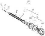
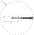
- Fig. 1is a schematic structural diagram of a multi-shot processing device for an endoscope provided by one of the embodiments at a first angle of view.
- Fig. 2is a cross-sectional view of the multiple treatment device for an endoscope shown in Fig. 1.
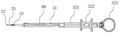
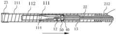
- FIG. 3is a schematic diagram of the structure of the multi-shot processing device for the endoscope shown in FIG. 1 at a second angle of view.
- Fig. 4is a cross-sectional view of the multiple treatment device for an endoscope shown in Fig. 3.
- Fig. 5is an enlarged schematic diagram of part A in Fig. 4.
- FIG. 6is a schematic diagram of the structure of FIG. 5 in another embodiment.
- Fig. 7is a schematic structural diagram of the mounting part provided by one of the embodiments.
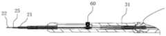
- Fig. 8is a schematic diagram of the structure of the multi-shot processing device for an endoscope with a part of the structure hidden.
- FIG. 9(a)is a schematic diagram of the three-dimensional structure of the first limiting portion provided by one of the embodiments.
- Fig. 9(b)is a schematic diagram of the first limiting part provided by one of the embodiments in one of the use states.
- Fig. 9(c)is a schematic diagram of the first restricting portion provided by one of the embodiments in one of the use states.
- Fig. 10is a schematic structural diagram of a manipulation member provided by one of the embodiments.
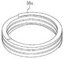
- FIG. 11is a schematic diagram of the structure of the second limiting part provided by one of the embodiments.
- Fig. 12is a schematic structural diagram of a second limiting portion provided by one of the embodiments.
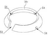
- Fig. 13is a schematic structural diagram of a second limiting portion provided by one of the embodiments.
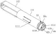
- FIG. 14is a schematic diagram of assembling the processing unit, the first limiting portion, and the second limiting portion provided by one of the embodiments.
- Fig. 15is a schematic diagram of assembling the capsule and the first restricting portion provided by one of the embodiments.
- FIG. 16is a schematic diagram of a three-dimensional structure of a base provided by one of the embodiments.
- Fig. 17is a schematic structural diagram of a second limiting portion provided by one of the embodiments.
- FIG. 18is a schematic diagram of assembling the processing unit, the first limiting portion, and the second limiting portion provided by one of the embodiments.
- FIG. 19is a schematic diagram of FIG. 18 from another perspective.
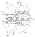
- Fig. 20is a cross-sectional view of a multiple treatment device for an endoscope provided by one of the embodiments.
- Fig. 21is an enlarged schematic diagram of part B in Fig. 20.
- Figure 22is a schematic diagram of the assembly of the capsule and the first limiting portion provided by one of the embodiments.
- FIG. 23is a schematic diagram of assembling the capsule and the first restricting portion provided by one of the embodiments.
- Fig. 24is a schematic structural diagram of a limiting structure provided by one of the embodiments.
- Fig. 25is a schematic structural diagram of a limiting structure provided by one of the embodiments.
- Fig. 26is a schematic diagram of the structure of a clamping arm provided by one of the embodiments.
- FIG. 27is a schematic diagram of the structure of the clamp arm shown in FIG. 26 from another perspective.
- Fig. 28is a schematic diagram of the assembly structure of the card firmware, the processing unit, and the manipulation member provided by one of the embodiments.
- FIG. 29is a schematic diagram of the structure of the card firmware provided by one of the embodiments.
- FIG. 30is a schematic diagram of the assembly structure of the clamping member, the processing unit, and the manipulation member provided by one of the embodiments.
- Fig. 31is a schematic diagram of the structure of a clamping arm provided by one of the embodiments.
- Fig. 32is a schematic structural diagram of a clamping arm provided by one of the embodiments in an active state.
- Fig. 33is a schematic structural diagram of a clamping arm provided by one of the embodiments in a self-locking state.
- Fig. 34is a schematic structural diagram of a clamping arm provided by one of the embodiments in an active state.
- FIG. 35is a schematic structural diagram of a processing unit in a self-locking state provided by another embodiment.
- Fig. 36is a schematic structural diagram of a multi-shot processing device for an endoscope provided by one of the embodiments.
- Fig. 37is a schematic view of the structure of the multi-shot processing device for the endoscope shown in Fig. 36 at a first angle of view.
- Fig. 38is a schematic cross-sectional view of Fig. 37.
- FIG. 39is a schematic diagram of the structure of the multi-shot processing device for the endoscope shown in FIG. 36 at a second angle of view.
- Fig. 40is a schematic cross-sectional view of Fig. 39.
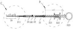
- Fig. 41is a cross-sectional view of the multi-shot processing device for endoscope provided by one of the embodiments in use.
- Fig. 42is an enlarged schematic diagram of part C in Fig. 41.
- Fig. 43is an enlarged schematic diagram of part D in Fig. 41.
- Figure 44is a cross-sectional view of part C in another state of use.
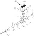
- Fig. 45is an exploded schematic diagram of the push component provided by one of the embodiments.
- Fig. 46is a structural diagram of a fixing seat provided by one of the embodiments.
- Fig. 47is a structural diagram of a locking member provided by one of the embodiments.
- Fig. 48is a schematic structural diagram of a handle portion provided by one of the embodiments.
- FIG. 49is a schematic diagram of the use state of the multi-shot processing device for endoscopes provided by one of the embodiments.
- Fig. 50is a schematic diagram of the use state of the multi-shot processing device for endoscope provided by one of the embodiments.
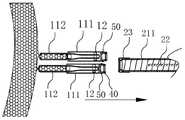
- FIG. 51is a schematic diagram of the use state of the multi-shot processing device for endoscopes provided by one of the embodiments.
- Fig. 52is an enlarged schematic diagram of part E in Fig. 51.
- Fig. 53is a schematic diagram of the use state of the multi-shot processing device for endoscope provided by one of the embodiments.
- Fig. 54is a schematic diagram of the use state of the multi-shot processing device for endoscope provided by one of the embodiments.
- FIG. 55is a schematic diagram of the use state of the multiple-shot processing device for endoscopes provided by one of the embodiments.
- Fig. 56is a schematic diagram of a use state of a multiple-shot processing device for an endoscope provided by another embodiment.
- Fig. 57is a schematic diagram of a use state of a multiple-shot processing device for an endoscope provided by another embodiment.
- Fig. 58is a schematic diagram of a use state of a multiple-shot processing device for an endoscope provided by another embodiment.
- Fig. 59is a schematic diagram of a use state of a multiple-shot processing device for an endoscope provided by another embodiment.
- Fig. 60is a schematic diagram of a use state of a multiple-shot processing device for an endoscope provided by another embodiment.
- Fig. 61is a schematic diagram of a use state of a multiple-shot processing device for an endoscope provided by another embodiment.
- Multi-shot processing devicefor endoscope-100; processing component-10; processing unit-11; capsule-111; card hole portion-1111; opening hole-1112; clamp arm-112; locking portion-1121; locking seat-1122 ;Base-113; Third through hole-1131; Limiting structure-114; Fastener-12; Pin-121; Bar-1211; Folding part-122; Spacer-13; Conveying component-20; Conveying Tube-21; First tube-211; Second tube-212; Manipulating member-22; Head-221; Inner concave part-222; Shoulder-223; Mounting part-23; First through hole-230; Seat body -231; stop-232; tooth-233; fourth through hole-234; flange-235; push tube-25; operating component-30; handle-31; second locking part-311; sliding groove- 312; marking part-313; sliding part-32; connecting rod-321; sliding finger ring-322; thumb ring-323; first limit part-40, 40a, 40b; cavity-400; extension part-41a; Setting portion-42a;
- a componentwhen a component is considered to be “installed on” another component, it may be directly installed on another component or a centered component may exist at the same time.
- a componentWhen a component is considered “connected” to another component, it can be directly connected to the other component or there may be a centered component at the same time.
- a componentWhen a component is considered to be “fixed” to another component, it can be directly fixed to the other component or there may be a centered component at the same time.
- orientation or positional relationship indicated by the terminology involvedis usually based on the orientation or positional relationship shown in the drawings, which is only for the convenience of describing the application and simplifying the description.
- these orientation wordsdo not indicate or imply that the device or element referred to must have a specific orientation or be constructed and operated in a specific orientation, and therefore cannot be understood as a limitation on the scope of protection of this application; the orientation word “inside” “Outside” refers to the inside and outside relative to the contour of each component itself.
- proximal and proximalare used herein to mean the end or side closer to the operator during the operation, and are the opposite of the terms “distal” and “distal” Position or direction; “distal” and “distal” refer to the end or side farther from the operator during the operation, and are the opposite position or direction to the terms “proximal” and “proximal”.
- the conventional multi-shot treatment device for endoscopescan continuously release multiple treatment units in the living body, and grasp the tissue around the wound to clamp the edge of the wound and achieve the effect of closing the wound.
- the clamping of the lesion partneeds to be adjusted by moving the treatment unit back and forth and rotating.
- the distal end of the processing unitcan be switched between open and closed states to realize the repeated opening and closing of the processing unit.
- the clamping angle of the processing unitcan be adjusted. And improve the accuracy of the clamping operation, so that the lesion can be better aligned and effectively clamped.
- the processing unitenters the living body through a 1m-2m flexible endoscope and is delivered to the lesion.
- the endoscopewill bend at a larger angle in the living body, which is easy to cause the traditional endoscope to be processed with multiple processing devices.
- the unitmay not be able to corner or transmit torque to the remote processing unit.
- the traditional processing devicecan also insert and release multiple processing units at a time to clamp multiple lesions, but after the previous processing unit is released, the latter processing unit is difficult to effectively load with the operating device and realize repeated opening , Resulting in failure or limitation of multiple functions. Therefore, in order to ensure the clamping operation and stable release of each processing unit, it is very important that each processing unit can be effectively loaded.
- the processing unitcan be repeatedly opened and closed before being released by providing an elastically deformable limit protrusion at the proximal end of the processing unit.
- the operating memberresists the limiting protrusion and can cause the limiting protrusion to expand radially outward.
- the limiting protrusioncan be radially contracted, and the limiting protrusion is elastically deformed and distant from the delivery tube.
- the processing unitrepeatedly opens and closes and clamps the lesion, the limiting protrusion of the proximal end can be constrained to the distal end of the delivery tube.
- the elastically deformed limit convexitywill interfere with the inner wall of the conveying pipe, which will affect the smooth movement of the processing unit in the conveying pipe and is not conducive to self-conveying.
- the tubeis released into the living body; and if the degree of radial deformation of the limiting protrusion is small, it is easy to detach from the distal end of the delivery tube, which is not conducive to repeated opening and closing operations.
- FIGS. 1 to 5Please refer to FIGS. 1 to 5 together.
- One of the preferred embodiments of the present applicationprovides a multi-shot processing device 100 for an endoscope, which does not interfere with the inner wall of the delivery tube 21 and can effectively perform repeated opening and closing operations.
- 1is a schematic view of the structure of the multi-shot processing device 100 for endoscopes provided by one of the embodiments at a first viewing angle
- FIG. 2is a cross-sectional view of the multi-shot processing device 100 for endoscopes shown in FIG. 1
- FIG. 3is a diagram A schematic view of the structure of the multi-shot processing device 100 for an endoscope shown in 1 at a second view angle
- FIG. 4is a cross-sectional view of the multi-shot processing device 100 for an endoscope shown in FIG. 3
- FIG. 5is an enlarged schematic view in FIG. 4.
- the multi-shot processing device 100 for an endoscopeincludes: a conveying assembly, an operating assembly, a processing unit 11, a first restricting portion 40b, and a second restricting portion 50c.
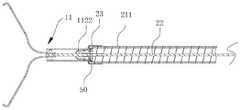
- the conveying assemblyincludes a conveying pipe 21, a manipulation member 22 and a mounting part 23.
- At least one processing unit 11is contained in the conveying tube 21, so that a plurality of processing units 11 can be continuously released when it is inserted into the living body at one time.
- the number of processing units 11is set to 2-10.
- the delivery tube 21is preferably, but not limited to, a spring hose, and a sleeve may be provided on the outside thereof, and the sleeve may be made of a flexible material.
- the delivery tube 21includes a first tube 211 and a second tube 212 coupled to the proximal end of the first tube 211.
- the first tube 211is wound by flat wire, and the second tube 212 is wound by round wire. to make.
- the first tube 211is made of a metal wire with a quadrilateral cross section. Compared with the second tube 212 made of a circular metal wire with a cross section, the first tube 211 has the same outer diameter.
- the wall thicknessis small and the inner diameter is large, which facilitates the movement of the processing unit 11 in the first tube 211.
- the first tube 211has a strong driving force, which is convenient for clamping the distal end of the delivery tube 21 in the living body. Support operation.
- first tube 211 and the second tube 212are fixed by welding. It can be understood that in other embodiments, the first tube 211 and the second tube 212 may also be screwed, riveted, or glued. Other fixing methods such as connection or card connection.
- the advantage of the segmented designis that it can reduce the overall manufacturing cost of the conveying pipe 21 while ensuring the necessary propulsion force and accommodating space.
- the manipulation member 22is penetrated in the delivery tube 21 and can drive the processing unit 11 from the combined configuration of the most distal processing unit 11 and the distal end of the delivery tube 21 to the most distal processing unit 11 detached from the distal release configuration of the delivery tube 21 Switch.
- the operating member 22is a rope, tube, or a single metal wire or tube wound by multiple metal wires with good torque transmission performance, and the diameter is 0.2mm to 1.0mm, which can realize 1:1 torque transmission.
- the operating member 22can move back and forth and rotate in the conveying pipe 21, and drive the processing unit 11 combined with it to move and rotate synchronously.
- the mounting portion 23is fixed to the distal end of the delivery tube 21 and includes a stop 232 extending toward the axis of the delivery tube 21.
- Each processing unit 11 accommodated in the conveying pipe 21needs to pass through the stop 232 before being released, and be clamped with the stop, so that the opening, closing and rotating operations of the clamping arm 112 can be realized through the manipulation member 22 . After the processing unit 11 is disconnected from the stopper, it will be released from the conveying pipe 21 and enter the living body.
- the operating assemblyincludes a handle portion 31 and a sliding portion 32 sleeved on the handle portion 31.
- the handle portion 31is combined with the proximal end of the delivery tube 21 for driving the delivery tube 21 to move synchronously.
- the sliding portion 32is connected to the proximal end of the manipulation member 22 and drives the manipulation member 22 and the processing unit 11 to move synchronously. In this way, the user can adjust the angle and distance between the processing unit 11 and the lesion by moving the handle portion 31 and the sliding portion 32 according to the needs of the lesion, so as to better align the lesion and clamp the tissue.
- the processing unit 11has a capsule 111 and a clamping arm 112, and the proximal end of the clamping arm 112 is accommodated in the capsule 111.
- the proximal end of the clamp arm 112is connected to the manipulation member 22 and can move back and forth relative to the axial direction of the capsule 111 under the action of the manipulation member 22.
- the distal end of the clamp arm 112can be switched between an open configuration and a closed configuration. After the clamping operation is completed, the processing unit 11 is in a closed configuration and fixed to the capsule 111.
- the multi-shot treatment device 100 for an endoscopeis provided with a first restricting portion 40b and a second restricting portion 50c.
- the first limiting portion 40bis arranged at the proximal end of the capsule 111, and can be elastically deformed or invalidated under the action of external force, which corresponds to the engagement or disengagement with the stop.
- the first limiting portion 40is located near the stop 232 and is clamped to the stop 232, and can restrict the movement of the processing unit 11 toward the distal end of the conveying tube 21.
- the manipulation member 22can move the clamping arm 112 between the open configuration and the closed configuration; in the release configuration, the first limiting portion 40 deforms under the action of the manipulation member 22 and is released from the stopper 232.
- the first limiting portion 40bcan be provided with a relatively small outer diameter to effectively engage with the stopper, so that the processing unit 11 will not interfere or jam the inner wall of the conveying pipe 21, and can ensure that the processing unit 11 is inside the conveying pipe 21
- the movementis smooth.
- the first limiting portion 40b and the capsule 111may be provided separately or integrally formed.
- the second limiting portion 50cis sleeved on the proximal end of the capsule 111, and passes through the stopper 232 together with the capsule 111, and the first limiting portion 40b is held at the distal end of the delivery tube 21.
- the second limiting portion 50 located at the distal end of the stopper 232abuts the distal end of the stopper 232 to restrict the movement of the balloon 111 toward the proximal direction of the delivery tube 21; the first limiting portion is located on the stopper 232 and clamped to the stop 232, the operating member 22 can move the clamping arm 112 between the open and closed configurations; in the released configuration, the first limit part is deformed under the action of the operating member 22 and released from the stop 232 Card access. In this way, the first limiting portion 40 can be better engaged with the proximal end of the stop 232 when the first limiting portion 40 is expanded outward, and adverse effects caused by excessive or small radial deformation of the first limiting portion 40 can be avoided.
- the second limiting portion 50may also be provided at the distal end of the delivery tube 21, and located at the proximal end of the stop 232 in the combined configuration; it may also be the second limiting portion 50 The number is set to two, and they are located at the distal end of the delivery tube 21 and the proximal end of the balloon 111 at the same time.
- the second limiting portionmay be provided at the distal end of the delivery tube 21 and located inside the stop 232 in the combined configuration, or may be provided at the proximal end of the capsule 111 and located outside the stop 232 in the combined configuration, or At the same time, it is arranged at the distal end of the delivery tube 21 and the proximal end of the balloon 111, thereby acting as a double limit.
- the second limitercan expand or contract outward along the radial direction of the delivery tube 21, and resist the stop 232, so that the capsule 111 can pass, while the first limiter that expands outward
- the portionis located at the proximal end of the delivery tube 21, so that the processing unit 11 can be opened or closed.
- the diameter of the through hole formed by the stop 232is larger than the outer diameter of the distal end of the first limiting portion and smaller than the outer diameter of the proximal end of the second limiting portion.
- the usercan pull the sliding finger ring 322 toward the proximal end of the delivery tube 21 to bring the clamping arm 112 together and lock it in the capsule 111, and then continue to face the delivery tube
- the proximal end of 21applies driving force.
- the applied driving forceis greater than the preset driving force value
- the distal end of the manipulation member 22is disconnected from the clamping arm 112, and the first limiting portion 40b is elastically retracted or deformed, and disengages from the engagement with the stopper, thereby completing The release of a processing unit 11. Repeat this operation to continue to complete the release of the processing unit 11 contained in the delivery pipe 21.
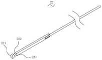
- the mounting portion 23is fixed to the distal end of the conveying pipe 21, and the mounting portion 23 and the conveying pipe 21 can be integrally formed or arranged separately, and fixed by screwing, welding, riveting, gluing or other means. .
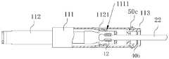
- the mounting portion 23includes a seat body 231 and a stop 232 formed by transitioning from the distal end of the seat body 231 to the axial side.
- the seat body 231is sleeved on the distal end of the delivery tube 21 and the seat body 231 is formed with an inner cavity (not shown in the figure). (Shown), the stopper 232 is provided with a first through hole through which the capsule 111 and the second limiting portion 50c pass, and the first through hole is used for limiting the first limiting portion.
- FIG. 6is a schematic diagram of the structure of FIG. 5 in another embodiment.
- the structure of Fig. 6is basically the same as that of Fig. 5, except that the mounting portion 23 also includes a flange 235 provided at the distal end of the stop.
- the flange 235extends from the distal end surface of the stopper 232 toward the distal end of the mounting portion 23, and a step surface (not shown) is formed between the inner side surface of the flange 235 and the distal end surface of the stopper 232, To limit the excessive expansion of the proximal end of the second limiting portion 50c.
- the capsule 111 and the second limiting portion 50 cpenetrate through the first through hole, and the second limiting portion 50 c abuts against the distal end surface of the stop 232. Since the proximal end of the second restricting portion 50c is expanded relative to the distal end and has a larger outer diameter, the proximal end of the second restricting portion 50c does not contact the outer side wall of the capsule 111, and is transported toward the Under the driving force in the proximal direction of the tube 21, the second limiting portion 50c may shake, and the structure is not stable enough.
- the flange 235is arranged so that the proximal end of the second limiting portion 50c can be accommodated at the distal end of the mounting portion 23, and the inner surface of the flange 235 can limit the proximal edge of the second limiting portion 50c to To prevent excessive shaking, the structure is relatively stable.
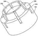
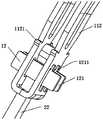
- FIG. 7is a schematic structural diagram of the mounting portion 23 provided by one of the embodiments
- FIG. 8is a schematic structural diagram of the multi-shot processing device 100 for an endoscope with a part of the structure hidden.
- the mounting portion 23also includes a tooth portion 233 formed along the axial transition from the stopper 232, a plurality of fourth through holes 234 are opened on the mounting portion 23, and the plurality of fourth through holes 234 are opposite to each other in the circumferential direction of the mounting portion 23. Arranged at intervals, the fourth through holes 234 respectively penetrate the distal end of the tooth 233 and transition to the stop 232 and the seat body 231 so that the tooth 233 can expand and contract radially.
- the plurality of fourth through holes 234radially split the tooth portion 233 of the mounting portion 23, and enable the tooth portion 233 to expand outward when receiving a radially outward resisting force, and the plurality of fourth through holes 234
- the arrangement of ⁇is easier to elastically deform the mounting portion 23 itself.
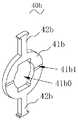
- Figure 9 (a)is a three-dimensional schematic diagram of the first limiting portion provided by one of the embodiments
- Figure 9 (b)is the first provided by one of the embodiments
- FIG. 9(c)is a schematic diagram of the first restricting portion provided by one of the embodiments in a stressed and failed state.
- the first limiting portion 40bincludes a first base 41b and a first protrusion 42b.
- the first base 41bis accommodated at the proximal end of the capsule 111, and the first protrusion 42b extends outward from the first base 41b until it protrudes from the capsule.
- the side wall of the body 111is thus confined to the proximal side of the stop 232.
- the number of the first convex portion 42bis set to two, and they are respectively connected to both ends of the first base portion 41b.
- the two first convex portions 42bare located on the same axis and arranged symmetrically.
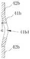
- the surface included angle ⁇ between the first base 41b and the first protrusion 42bis less than or equal to 30°, and the first base 41b may be bent toward the proximal end or toward the distal end relative to the first protrusion 42b.
- the first base portion 41b and the first convex portion 42bare preferably located on the same plane.
- the proximal end surface of the first base portion 41bis provided with a mutable portion 41b1, the changeable portion 41b1 is used to deform or fail the first base 41b when the first base 41b is stressed.
- the variable portion 41b1may be an opening or a slot provided on the first base portion 41b.
- the variable portion 41b1is substantially in the shape of a groove and penetrates the proximal end surface of the first base portion 41b.
- the changeable portion 41b1is located on the central axis of the first base portion 41b and is perpendicular to the axis directions of the two first convex portions 42b.
- the changeable portion 41b1may also be provided at other positions on the proximal end surface of the first base portion 41b, and may be in the shape of a hole or slot that does not penetrate, without affecting the deformation or failure of the first limiting portion 40b. Under the premise of, the present application does not limit the structure and location of the mutagenic portion 41b1.
- the center of the first base 41bis formed with a second through hole 41b0 through which the manipulation member 22 passes.
- the distal end of the manipulation member 22passes through the second through hole 41b0 and is combined with the processing unit 11 to drive the processing unit 11 to move synchronously and manipulate
- the distal end of the member 22does not relatively rotate in the second through hole 41b0.
- the distal section of the manipulation member 22is set in a non-circular structure, and its cross-section is roughly rectangular, and the proximal section of the manipulation member 22 is set in a cylindrical structure, which is convenient for synchronous movement in the delivery tube 21 and does not affect other unloaded
- the processing unit 11makes an impact.
- FIG. 10is a schematic structural diagram of the manipulation member 22 provided by one of the embodiments.
- the distal end of the manipulation member 22has a head 221, an inner concave portion 222, and a shoulder 223 in sequence from far to near, so that the manipulation member 22 drives the most distal processing unit 11 to move synchronously.
- the outer diameter of the parts of the manipulation member 22 except the head 221is smaller than the inner diameter of the circular hole.
- the shape of the second through hole 41b0is adapted to the distal end of the manipulation member 22
- the minimum inner diameter of the second through hole 22is smaller than the maximum outer diameter of the head 221, and is approximately a rectangular hole, and the two long sides of the cross section of the second through hole 41b0 are respectively convex and form a circular hole.
- the diameter of the manipulating member 22is larger than the outer diameter of the proximal end of the manipulating member 22, so that the proximal end of the manipulating member 22 can rotate in the second through hole 41b0; the diameter of the circular hole is smaller than the maximum outer diameter of the head 221 of the manipulating member 22 Therefore, the head 221 is restricted from moving in the proximal direction of the first base 41b and rotating in the second through hole 41b0.
- the head 221passes through the rectangular hole from the proximal side to the distal side of the first base 41b, and then rotates the manipulation member 22.
- the outer diameter of the manipulation member 22 except for the head 221is smaller than the inner diameter of the circular hole, so that it can be passed through.
- the head 221After the head 221 rotates at a certain angle, the head 221 can abut on the peripheral wall of the second through hole 41b0, so that the second through hole 41b0 cannot be withdrawn in the reverse direction.
- the reverse withdrawal directionrefers to the reverse of the traveling direction when the head 221 passes through the second through hole 41b0.
- FIGS. 11 to 13are respectively structural schematic diagrams of the second limiting portion 50 provided by different embodiments of the present application.
- the second limiting portion 50a provided in FIG. 11is a cylindrical spring.
- the second limiting portion 50b provided in FIG. 12may be a tower spring, and the outer diameter of the tower spring gradually decreases along the direction toward the distal end of the delivery pipe 21.
- the second limiting portion 50c provided in FIG. 13is provided with a first opening 53.
- the first opening 53transitions along the axis of the second limiting portion 50c to provide a margin of deformation and facilitate the second limiting portion 50c itself. Radial elastic deformation.
- the inner diameter of the second limiting portion 50 b or 50 cdecreases from the proximal end of the delivery tube 21 toward the distal end of the delivery tube 21.
- the second limiting portion 50is disposed at the distal end of the delivery tube 21 and is accommodated on the proximal side of the stop 232. In the state of not receiving a radial force, the second limiting portion 50 is farther away
- the inner diameter of the endis smaller than the outer diameter of the processing unit 11, and the inner diameter of the proximal end of the second limiting portion 50 is larger than the outer diameter of the processing unit 11.
- the side wall of the second limiting portion 50is provided with a first opening 53 that can provide a margin for deformation, and the first opening 53 penetrates the side wall of the second limiting portion 50; and/or, the second The side wall of the limiting portion 50 is further provided with a second opening 54.
- the second opening 54extends from the proximal end surface of the side wall of the second limiting portion 50 to the side wall of the second limiting portion 50.
- the second opening 54The number is set to be multiple, and the multiple second openings 54 are arranged at intervals along the circumferential direction of the second limiting portion 50.
- the arrangement of the first opening 53 and/or the second opening 54can reduce the radial reaction force of the distal end of the second limiting portion 50 when passing through the stop 232, so as to facilitate the second limiting portion 50 to be pushed out of the conveying tube 21. It should be noted that after the second limiting portion 50 is pushed out from the stopper 232, its distal end returns to expand radially outward to better resist the distal end of the stopper 232.
- FIG. 14is an assembly diagram of the processing unit 11 and the first limiting portion 40b and the second limiting portion 50c provided by one of the embodiments.
- the first limiting portion 40 bis received at the proximal end of the capsule 111 to resist the proximal end surface of the stop 232, and the second limiting portion 50 c is sleeved on the proximal end of the capsule 111.
- FIG. 15is a schematic diagram of the assembly of the capsule 111 and the first limiting portion 40b provided by one of the embodiments
- FIG. 16is a schematic diagram of the three-dimensional structure of the base 113 provided by one of the embodiments.
- the processing unit 11further includes a base 113 which is fixed to the proximal end of the capsule 111.
- the base 113has an accommodation cavity for accommodating the first base 41b.
- the side wallis provided with a third through hole 1131 through which the first protrusion 42b extends.
- the base 113 and the proximal end of the capsule 111are fixed by welding.
- FIG. 17is a schematic structural diagram of the second limiting portion 50d provided by one of the embodiments
- FIG. 18is the processing unit 11 and the first limiting portion 40b and the second limiting portion 40b provided by one of the embodiments.
- FIG. 19is a schematic diagram of FIG. 18 from another perspective.
- the second limiting portion 50dincludes a second base portion 51d and a second convex portion 52d.
- the second base portion 51dis accommodated in the capsule 111, and the second convex portion 52d extends outward from the second base 51d until it protrudes from the capsule 111
- the side wall, and the limit stop 232may be a fixing method such as welding, riveting, clamping, and hinge.
- the second base 51dmay be provided with a first opening 53 so as to facilitate the passage of the second limiting portion 50d through the stopper 232.
- the number of the second convex portions 52dis set to be multiple, and they are arranged at intervals along the circumferential inward direction of the second base portion 51d.
- the side wall of the bag body 111is provided with a plurality of openings 1112 through which the second protrusion 52d extends.
- FIG. 20is a cross-sectional view of an endoscope multi-shot processing device 100 provided by one of the embodiments;
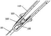
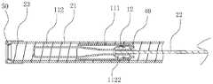
- FIG. 21is an enlarged schematic view of part B in FIG. 20;
- FIG. 22is one of the embodiments
- a schematic diagram of the assembly of the capsule 111 and the first limiting portion 40ais provided.
- the inner surface of the first limiting portion 40a of the preferred embodimentis formed with a cavity 400 through which the manipulation member 22 passes.
- the distal end of the manipulation member 22passes through the cavity 400 and is connected to the processing unit 11.
- the first restricting portion 40acan be elastically deformed under the resistance of the manipulation member 22, and expand outward along the circumferential direction of the balloon 111 to be clamped with the distal end of the delivery tube 21; When the proximal end of 21 drives the manipulation member 22, the manipulation member 22 will be separated from the cavity 400, and the first limiting portion 40a can contract along the circumferential direction of the balloon 111 to release the clip from the distal end of the delivery tube 21. At this time, the balloon 111 and the first limiting portion 40a can be released from the distal end of the delivery tube 21.
- the center of the first limiting portion 40ais formed with a channel 400 through which the manipulation member 22 passes.
- the distal end of the manipulation member 22passes through the channel 400 and is connected to the processing unit 11, and the second limiting portion 50c is located in the delivery tube.
- the distal end of 21is located near the stop 232.
- the first limiting portion 40aincludes an extension portion 41a, a clamping portion 42a, and an inwardly retracted portion 43a.
- the extension portion 41ais connected to the side wall of the capsule 111
- the clamping portion 42ais connected to the proximal end of the extension portion 41a.
- the inner surface of the locking portion 42aextends inward and is formed with a locking protrusion 42a1.
- the locking protrusion 42a1can be elastically deformed under the resistance of the manipulation member 22, and expand outward in the radial direction of the capsule 111 to be locked with the distal end of the second limiting portion 50c.
- the outer side surface of the retracted portion 43aabuts against the inner side surface of the second limiting portion 50c
- the distal end surface of the clamping portion 42aabuts against the proximal end surface of the second limiting portion 50c
- the proximal end surface of the extension portion 41aabuts against the inner surface of the second limiting portion 50c. It is held on the distal end surface of the second limiting portion 50c.
- the capsule 111can be more firmly clamped to the distal end of the stop 232.
- the locking portion 42ais elastically retracted, and will not interfere or jam the inner wall of the delivery tube 21, which is beneficial to the processing unit 11 in the endoscope.
- the clamp channelis bent at a limit of 180° or more, it can be transported freely in the lumen of the small delivery tube 21.
- the proximal end of the extension part 41ais flush with the proximal end of the capsule 111, and there is a gap between the extension part 41a and the side wall of the capsule 111. It can be understood that the extension 41a may also be connected to the proximal end of the balloon 111.
- the proximal inner diameter of the central through hole of the second restricting portion 50cis smaller than the outer diameter of the clamping portion 42a and greater than or equal to the outer diameter of the balloon 111, and the inner diameter of the central through hole of the second restricting portion 50c is from the proximal end to the distal end Reduce, so that the processing unit 11 is driven to move distally while generating an urging force for radially expanding the second limiting portion 50c, so that the balloon 111 cannot follow the delivery tube after passing through the second limiting portion 50c.
- the longitudinal direction of 21moves back and forth, so that the processing unit 11 is held at the distal end of the delivery tube 21 by the first limiting portion 40 a and the second limiting portion 50 c.
- the inner diameter of the first through hole 230is larger than the outer outer diameter of the distal end of the second limiting portion 50c, and smaller than the outer diameter of the proximal end of the second limiting portion 50c.
- the distal end of the second limiting portion 50cresists the step surface between the locking portion 42a and the retracted portion 43a, and the proximal end of the stop 232 resists the distal surface of the first limiting portion 40a ,
- the manipulation member 22can move the clamping arm 112 between the open configuration and the closed configuration, and the outer diameter of the first limiting portion 40a is larger than the diameter of the first through hole 230 and the inner diameter of the second limiting portion 50, whichever is larger.
- the proximal side movement of the sliding portion 32releases the coupling relationship between the manipulation member 22 and the processing unit 11 and the first limiting portion 40a, and when the manipulation member 22 is driven toward the proximal end of the delivery tube 21 by a relatively large driving force, The manipulation member 22 will be separated from the cavity 400, the first limiting portion 40a can contract in the radially inward direction of the capsule 111, so that the locking portion 42a and the distal end of the second limiting portion 50c can be released from the clamping.
- the combination of a limiting portion 40 a and the stopper 232fails.
- the outer diameter of the first limiting portion 40 ais smaller than the smaller of the diameter of the first through hole 230 formed by the stopper 232 and the inner diameter of the second limiting portion 50. At this time, the balloon 111 and the first restricting portion 40a can be released from the distal end of the delivery tube 21.
- the extension 41a and the side wall of the capsule 111can be integrally formed or arranged separately, and connected to the side wall of the capsule 111 by screwing, welding, riveting or other common fixing methods, which is not provided in this embodiment. limit.
- the number of the first limiting portion 40ais set to be multiple, and the multiple first limiting portions 40a are arranged symmetrically with respect to the side wall of the capsule 111, without affecting the first limiting portion 40a.
- the number and arrangement of the first limiting portion 40aare not limited in this application.
- the plurality of first limiting portions 40amay also be arranged at intervals along the circumferential direction of the capsule 111.
- the number of the first limiting portion 40ais set to two, and they are arranged symmetrically with respect to the circumferential direction of the capsule 111. It can be understood that, in other embodiments, the number of the first limiting portion 40a can be set to 3 or more.
- the present applicationis The number and arrangement of a limiting portion 40a are not limited.
- FIG. 23is an assembly diagram of the capsule 111 and the first limiting portion 40 a provided by one of the embodiments.
- the processing unit 11further includes an elastic member 44a sleeved on the inwardly retracted portion 43a, and the inner surface of the elastic member 44a resists the inner surface.
- the outer surface of the receiving portion 43ais an assembly diagram of the capsule 111 and the first limiting portion 40 a provided by one of the embodiments.
- the diameter of the first limiting portion 40acan be made smaller without interference or jamming on the inner wall of the conveying pipe 21, which is beneficial to the processing unit 11
- the endoscope clamp channelis bent at a limit of 180° or more, it can be transported freely in the lumen of the small delivery tube 21.
- the elastic member 44ais preferably, but not limited to, an elastic ring.
- the inner wall surface of the protruding portion 42a1abuts the outer wall surface of the operating member 22, and the first limiting portion 40a And the elastic member 44a is in an elastically expanded state.
- the manipulation member 22is disconnected from the processing unit 11 and separated from the cavity 400, the retracted portion 43a shrinks radially inward under the elastic force of the elastic member 44a, so that the processing unit 11 can pass through the block 232 .
- the first limiting portion 40acan also be made of elastic material and contract radially inwardly by virtue of its own resilience.
- the processing unit 11further includes a limiting structure 114 (as shown in FIG. 20) accommodated in the clamping arm 112.
- the manipulation member 22passes through the limiting structure 114 and is limited by the limiting structure 114 in the direction in which the head 221 abuts the fastener 12 proximally, so that when the operating member 22 moves toward the proximal direction of the delivery tube 22, the operating member 22 is restricted.
- the limiting structure 114is substantially tubular, and the cross-sectional shape of the central cavity matches the outer side surface of the manipulation member 22.
- the radial maximum outer diameter of the limiting structure 114is smaller than the minimum gap between the two clamping arms 112 in the closed configuration.
- FIG. 24 and FIG. 25are schematic structural diagrams of the limiting structure 114 provided by different embodiments.
- FIG. 24provides a limiting structure 114a with a rectangular cross-section
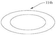
- FIG. 25provides a limiting structure 114b with an elliptical cross-section.
- the operating member 22is driven toward the proximal direction of the delivery tube 21.
- the manipulation member 22can only move relative to the axial direction of the conveying pipe 21 under the action of the limiting structure 114 until the connection with the processing unit 11 is completed.
- the clamping arm 112 of the latter processing unit 11is in the open configuration, the limiting structure 114 can fall from the processing unit 11 into the body of the organism.
- the limiting structure 114can be provided separately from the clamping arm 112 or can be integrally formed with the clamping arm 112. Specifically, please refer to FIGS. 26 and 27 together to provide a limiting structure 114c integrally formed with the clamp arm 112.
- the limiting structure 114cis a protrusion provided on the inner side wall of the clamping arm 112, and the protrusion is formed by a part of the inner side wall of one of the clamping arms extending toward the opposite direction of the other clamping arm to reduce the size of the two clamping arms. And make the gap between the limiting structures 114c smaller than the maximum outer diameter of the manipulation member 22 to limit the circumferential rotation of the manipulation member 22 relative to the clamp arm 112.
- FIG. 28is a schematic diagram of the assembly structure of the fastener 12, the processing unit 11, and the manipulation member 22 provided by one of the embodiments.
- the processing unit 11includes two clamping arms 112 arranged opposite and spaced apart, and the processing unit 11 includes a fastener 12 arranged between the two clamping arms 112.
- the inner concave portion 222is fixed between the two clamping arms 112 by the fastener 12
- the fastener 12is respectively against the proximal side of the head 221 and the distal side of the shoulder 223, the fastener 12 can be directed under a predetermined pressure
- the connection between the fastener 12 and the concave portion 222will be slightly deformed or broken, and the manipulation member 22 will fall off the processing unit 11. Further, the distal end of the shoulder 223 inclines inward toward the central axis to ensure that the manipulation member 22 is clamped to the proximal end of the fastener 12, thereby driving the processing unit 11 to rotate.
- the clamping member 12includes two pin pieces 121, two pin pieces 121 both pass through two clamping arms 112, and the pin pieces 121 can be clamped against the two end surfaces of the inner recess 222 and limit the operating member 22.
- the two pin pieces 121may adopt a split structure.
- the pin 121penetrates through two clamping arms 112.
- the pin 121includes a first end and a second end.
- a stop bar 1211is provided on the first end.
- the stop bar 1211is used to limit the pin 121 and connect the first end.
- One endis fixed on the clamp arm 112, and the second end is a movable end. With this arrangement, when the fastener 12 is under force, the movable end can move toward the first end to provide a margin for deformation, so as to facilitate the disconnection of the operating member 22 and the fastener 12.
- FIG. 29is a schematic diagram of the structure of the card firmware 12 provided in one of the embodiments.
- the two pin pieces 121are integrally formed and arranged in a U shape. This arrangement facilitates the installation of the fastener 12 on the clamping arm 112.
- FIG. 30is a schematic diagram of the assembly structure of the fastener 12, the processing unit 11, and the manipulation member 22 provided by one of the embodiments.
- the fastener 12includes a folded portion 122 that transitions from the clamping arm 112 toward the operating member 22 and is formed. Specifically, each clamping arm 112 is formed with a folded portion 122 that transitions toward two sides of the inner recess 222, and two The folded portion 122 on the clamping arm 112 is cooperatively fitted and enclosed with the clamping arm 112 for engaging the two end surfaces of the inner concave portion 222.
- the folded portion 122 and the clamping arm 112are formed integrally, and the two folded portions 122 on each clamping arm 112 are formed by transitioning from a part of the middle position of the clamping arm 112 to the inner concave portion 222. .
- a self-locking functionneeds to be provided on the processing unit 11 so that the clamping arm 112 can be locked in Inside the capsule 111.
- the proximal end of the clamp arm 112is movably accommodated inside the capsule 111.
- the clamp arm 112can be relative to the axial direction of the capsule 111. Move to adjust the distance and angle between the clamping arm 112 and the target tissue, and the opening angle of the clamping arm 112.
- the manipulation member 22is operated proximally to drive the clamping arm 112 to move synchronously, so that the clamping arm 112 is contained in the capsule 111 and locked, and the clamping arm 112 is closed.
- FIG. 31is a schematic structural diagram of the clamp arm 112 provided by one of the embodiments
- FIG. 32is a schematic structural diagram of the clamp arm 112 provided by one of the embodiments in an active state
- FIG. 33is a schematic diagram of the clamp arm 112 provided by one of the embodiments.
- An embodimentprovides a schematic structural diagram of the clamp arm 112 in a self-locking state.
- a part of the side wall at the proximal end of the clamp arm 112extends outward and forms a locking portion 1121, and a part of the side wall of the capsule body 111 is bent inward to form a locking hole 1111 on the side wall of the capsule body 111.
- the hole portion 1111fits with the locking portion 1121 and is used for restricting the movement of the clamping arm 112 toward the distal end of the capsule 111.
- the operating member 22passes through the capsule 111 and is connected to the clamp arm 112. At this time, the clamp arm 112 can move relative to the axial direction of the capsule 111.
- the self-locking statethe operating member 22 is disconnected from the clamp arm 112. The distal end of the clamping arm 112 is closed and locked in the capsule 111.
- FIG. 34is a schematic structural diagram of the clamp arm 112 provided in one of the embodiments in an active state.
- a locking seat 1122that fits with the proximal end of the clamp arm 112 is fixed on the inner wall of the capsule 111.
- the manipulation member 22is operated in the proximal direction, the proximal end of the clamp arm 112 is clamped to the locking seat by a driving force.
- the self-locking of the clamp arm 112can also be realized.
- the locking seatcan be integrally formed with the inner wall of the bag body 111, or can be arranged separately. It should be noted that, provided that the self-locking effect of the clamping arm 112 is not affected, the present application does not limit the self-locking manner of the clamping arm 112.
- a spacer 13is provided between two adjacent processing units 11 (as shown in FIG. 20 ).
- the spacer 13separates the two adjacent processing units 11, and the spacer 13 is sleeved on the operating member 22.
- each processing unit 11is spaced apart. On the one hand, it can prevent the processing units 11 from interacting and be damaged; on the other hand, it can prevent the subsequent processing units 11 from being excessively exposed when the processing unit 11 is pushed out and causing the capsule.
- the end surface of 111cannot be received in the delivery tube 21, resulting in failure of the device.
- the inner diameter of the spacer 13is larger than the outer diameter of the manipulation member 22, so that the manipulation member 22 can smoothly reach the position of the next processing unit 11 from the inner hole of the spacer 13 so that the next processing unit 11 can be controlled.
- a plurality of processing unitsare placed in the delivery tube, and the manipulation member can move back and forth or rotate to drive the processing unit to switch between the combined configuration and the released configuration.
- the operating assembly located at the proximal end of the multi-shot processing devicehas a sliding part combined with the proximal end of the operating member, and the sliding part can drive the operating member to move.
- the processing unit located at the distal endis released, by operating the sliding portion proximally and driving the manipulation member to move, the manipulation member is combined with the subsequent processing unit until the processing unit is released, and then the sliding portion is moved by moving the sliding portion. Repeat the operation on the manipulation member and continue to release the next processing unit.
- the useroperates the multi-shot processing device for the endoscope with one hand and the other hand is used to operate the endoscope. Therefore, the movement stroke s1 of the sliding part is affected by the palm of the user's palm (the thumb and index finger are connected). Part) The span is limited, and considering the convenience of operation, the moving stroke s3 of the sliding part that can drive the operating member is relatively limited. In this way, for the processing unit located relatively close to the proximal end of the conveying tube, it is difficult to effectively combine with the manipulating member due to its s2 located outside the movement stroke of the manipulating member, which will result in the inability to accommodate more processing units in the conveying tube, which limits The further application of multiple processing devices for endoscopes.
- FIGS. 36 to 40One of the preferred embodiments of the present application provides a multi-shot processing for endoscopes that can accommodate more processing units 11 and enable each processing unit to be effectively loaded. ⁇ 100 ⁇ Device 100.
- the multi-shot processing device 100 for an endoscopeincludes a processing assembly 10, including two or more processing units 11, and the proximal end of the processing unit 11 has a first limiting portion that can deform or fail under the action of an external force.
- the delivery assembly 20includes a delivery tube 21 for accommodating the processing assembly 11, a push tube 25 through the delivery tube 21, and a manipulation member 22 through the push tube 25, wherein the distal end of the push tube 25 resists The processing unit 11 on the near side.
- the operating assembly 30includes a handle portion 31 combined with the proximal end of the delivery tube 21 and a sliding portion 32 combined with the proximal end of the manipulation member 22 to control the opening and closing and release of the distal processing unit 11.
- a pushing assembly 60arranged on the handle portion 31, wherein the pushing assembly 60 includes a fixing seat 61 fixed to the proximal end of the pushing tube 25.
- the handle portion 31is provided with a sliding groove 312 for the support seat 61 to slide, and the handle portion 31 is provided along the sliding groove 312 with a mark that cooperates with the fixed seat 61 and indicates the number of the processing unit 11.
- a push tube 25is provided in the delivery tube 21, and the manipulation member 22 penetrates the push tube 25.
- the material of the push tube 25includes at least one of PTFE (polytetrafluoroethylene), HDPE (high density polyethylene), and Peek (polyether ether ketone), which can reduce the friction between the manipulation member 22 and the delivery tube 21 , So that the manipulation member 22 can advance and retreat freely in the delivery tube 21, and the distal end of the push tube 25 is directly or via the spacer 13 (see FIG. 53) against the nearest processing unit 11.
- the push tube 25has a small diameter and limited driving force. In order to avoid bending of the push tube 25 during the pushing process, the spacer 13 can act on the processing assembly 10 indirectly.
- the processing unit 11 located at the proximal end of the delivery tube 21can move in the distal direction, so that the manipulation member 22 can target the processing unit 11 located outside the original loading stroke s2. Perform effective loading and operation.
- s1represents the movement stroke of the sliding ring 322, and s3 represents the stroke that the manipulation member 22 can effectively load the processing unit 11.
- s1s3.
- the s2 at the proximal end of s3indicates that the manipulation member 22 cannot effectively load the processing unit 11 located in the range by operating the sliding ring 322. Therefore, in this embodiment, the push tube 25 is moved to the distal end of the delivery tube 21.
- the processing units 11 located at s2can be moved to s3 one by one.
- the pushing assembly 60 of this embodimentincludes a fixing seat 61 that is sleeved on the pushing tube 25 and fixedly connected to the pushing tube 25.
- the fixing seat 61can drive the pushing tube 25 relative to the push tube 25 under the action of external force.
- the conveying pipe 21moves. In this way, by operating the operating member 22 through the sliding ring 322 and operating the push tube 25 through the push assembly 60, the multiple processing units 11 located in the delivery tube 21 can all be effectively loaded.
- the fixing seat 61is sleeved on the pushing tube 25.
- the fixing seat 61is provided with a shaft hole (not shown in the figure) for the pushing tube 25 to penetrate, and the fixing seat 61 can be fixed to the pushing tube 25 by glueing.
- the fixing base 61 and the push tube 25can also be fixed by riveting, welding, clamping, and the like.
- the fixing seat 61can also be fixed to the outer side wall of the pushing tube 25. Under the premise of not affecting the synchronous movement of the fixing seat 61 and the pushing tube 25, the present application does not limit the structure and the installation position of the fixing seat 61.
- the pushing assembly 60further includes a locking member 62 and a resetting member 63.
- the locking member 62is connected to the fixing base 61, and the resetting member 63 is disposed between the fixing base 61 and the locking member 62 and abuts against the locking member 62.
- 62is provided with a first locking portion 621
- the handle portion 31is provided with a second locking portion 311.
- the first locking portion 621can be engaged or disengaged with the second locking portion 311, so that the locking member 62 and the handle portion 31 Lock or unlock.
- the push tube 25cannot move.
- the manipulation member 22needs to be operated from the distal end of the delivery tube 21 to the proximal direction. At this time, it is necessary to ensure that the processing unit 11 cannot move closer to the delivery tube 21. Otherwise, it will cause the manipulation member 22 and the processing unit 11 to move proximally at the same time, so that the manipulation member 22 cannot effectively load the processing unit 11. Therefore, in this embodiment, when the push tube 25 is in the locked state, the processing assembly 10 cannot move toward the proximal direction of the delivery tube 21 due to the restriction of the push tube 25, so the effective loading of each processing unit 11 in the locked state can be ensured.
- the resetting member 63is disposed between the fixing seat 61 and the locking member 62, and one end of the resetting member 63 abuts against the fixing seat 61, and the other end abuts against the locking member 62, so that the locking member 62 always has and The tendency of the second locking portion 311 to engage.
- the first locking portion 621 and the second locking portion 311can also be locked in other ways, such as snapping, magnetic attraction, and so on.
- the first locking portion 621 on the locking member 62is arranged in a rack.
- the locking member 62 and the handle portion 31can be unlocked.
- the locking member 62can be moved along the axis of the conveying pipe 21, and the fixed seat 61 and the pusher can be driven.
- the tube 25moves synchronously.
- the locking member 62moves toward the handle portion 31 under the action of the reset member 63, and the locking with the second locking portion 311 is restored.
- the number of the second locking portion 311is set to be multiple arranged along the moving direction of the fixing seat 61, and is arranged in a continuous rack.
- the movement stroke of the first locking portion 621 and the second locking portion 311 after unlocking, moving and relocking oncecorresponds to the length of one processing unit 11.
- the fixing seat 61is provided with a guide post 611 extending toward the locking member 62, and the locking member 62 is provided with a guide groove 622 into which the guide post 611 extends.
- the locking member 62can be locked relative to The piece 62 moves along the axial direction of the guide post 611. In this way, guiding the movement of the locking member 62 can make the unlocking and locking operations more stable and reliable.
- the locking member 62is also provided with a protruding portion 623 that can protrude from the side wall of the handle portion 31 in a locked configuration, and the side wall of the handle portion 31 is correspondingly provided with a sliding groove 312 that matches and moves with the protruding portion 623.
- knurling(not shown) is provided on the end surface of the extension 623 to increase the friction of the extension 623 and facilitate its moving operation.
- the second locking portion 311is provided on the inner wall of the handle portion 31, and the first locking portion 621 is located on the end surface of the locking member 62 facing the second locking portion 311. It can be understood that the second locking portion 311 may also be disposed on the side wall of the sliding groove 312, and the first locking portion 621 is relatively located on the end surface of the locking member 62 facing the second locking portion 311.
- a marking portion 313is provided on the handle portion 31, and the number of the marking portions 313 is set to one or more, and is used to mark the number of remaining processing units 11 in the conveying pipe 21.
- the arrangement and number of the marking parts 313can be adjusted according to the number of processing units 11 contained in the conveying pipe 21.
- the number of the marking parts 313is set to a plurality of equidistantly arranged along the moving direction of the fixing seat 61.
- the marking part 313selects a digital marking. It can be understood that the marking portion 313 may also adopt other marking methods such as pattern marking.
- the pushing assembly 60further includes a crimping member 64 which is sleeved on the pushing tube 25 and fixedly connected to the fixing seat 61.
- the number of crimping elements 64is set to two, and the two crimping elements 64 are respectively fixed to the two ends of the fixing base 61.
- FIGS. 49 to 61are schematic diagrams of the multi-shot processing device for endoscopes provided by one of the embodiments in different use states.
- FIGS. 56 to 61are internal views provided by another embodiment. Schematic diagram of the state of use of the multiple processing device for speculum.
- the method of using the multiple treatment device for an endoscopeincludes the following steps: the first step is to release a treatment unit located at the distal end of the delivery tube, and then drive the manipulation member toward the proximal end of the delivery tube until a certain drive is reached. Under the force, the manipulation member cannot be further driven in the proximal direction, and the first user feedback of the combination of the processing unit and the manipulation member is obtained.
- the first user feedbackincludes the sound of the combination of the manipulation member and the processing unit and the operation that cannot be further pulled. At this time, the manipulation member can drive the processing unit to move synchronously.
- the second stepis to drive the manipulation member to the distal direction of the delivery tube until the manipulation member cannot be further driven in the distal direction under a certain driving force, and obtain the second user feedback that the first limit part is engaged with the second limit part .
- the second user feedbackincludes the snapping sound of the first limiting portion and the second limiting portion and the operation that cannot be further pulled.
- the manipulation membercan drive the processing unit to move back and forth and rotate relative to the capsule, so as to perform repeated opening, closing and rotating operations on the processing unit until the processing unit completes the clamping operation.
- the manipulation memberis driven toward the proximal end of the delivery tube, the first limiting part is deformed (as shown in FIG. 52) or fails, and the processing unit is released.
- the method of using the multiple processing device for an endoscopeincludes the following steps: the first step is to move the sliding part to the distal direction of the delivery tube, so that the multiple processing units located in the moving stroke of the sliding part are manipulated The components are driven and released one by one.
- the second stepis to press the push assembly and move the push assembly to the distal direction of the conveying tube, so that the multiple processing units located outside the moving stroke of the sliding part are driven by the push tube and released one by one.
- the method of using the multiple-shot processing device for endoscopesis based on the multiple-shot processing device for endoscopes.
- the multiple-shot processing device for endoscopesincludes a processing component, a delivery component, and a push component.
- the processing componentincludes two More than one processing unit
- the pushing assemblyincludes a delivery tube for accommodating the processing assembly, a pushing tube passing through the delivery tube, and a manipulation member passing through the pushing tube, wherein the pushing The distal end of the tube abuts against the proximal processing unit; the pushing component is fixedly connected to the proximal end of the pushing tube.
- the method of useincludes the following steps: in the first step, after releasing the most distal processing unit of the delivery tube, drive the operating member proximally relative to the delivery tube until an indication is obtained that the latter processing unit is far from the operating member. First user feedback combined with end-to-end.
- the second stepis to further drive the pushing assembly to the distal side relative to the delivery tube, and move the processing unit to the distal end of the delivery tube through the pushing tube fixed to the pushing assembly, until an indication of the latter processing unit is obtained Second user feedback combined with the distal end of the delivery tube.
- the third stepafter obtaining the second user feedback, drive the operating component so that the farthest processing unit can be opened and closed freely to obtain the desired action posture.
- the pushing assemblyincludes a fixing seat, a locking member, and a resetting member, the resetting member abuts between the fixing seat and the locking member, and the locking member is provided with a second locking part on the handle.
- the first locking partis matched; the above second step also includes: further driving the push assembly distally relative to the delivery tube, and when the push tube is moved, the locking member is pressed to unlock the first locking part and the second locking part ; After obtaining feedback from the second user, release the locking member to restore the locking of the first locking portion and the second locking portion.
- the method of using the multiple treatment device for an endoscopeincludes the following steps: the first step is to release the treatment unit at the farthest end of the delivery tube, and then drive the manipulation member proximally relative to the delivery tube until the instruction is obtained.
- a processing unitis combined with the first user feedback of the distal end of the manipulation member.
- the second stepis to further drive the pushing assembly to the distal side relative to the delivery tube.
- press the locking memberto unlock the first locking part and the second locking part; after obtaining feedback from the second user, release the locking To restore the locking of the first locking part and the second locking part.
- the third stepafter obtaining the second user feedback, drive the operating component so that the farthest processing unit can be opened and closed freely to obtain the desired action posture.
- the processing units contained in the delivery tubecan be released one by one, and the user can insert the multi-shot processing device for the endoscope at one time to release multiple processing units to clamp the lesion, which can greatly reduce the operation time and provide the patient Fighting for rescue time with medical staff also greatly reduces labor intensity and reduces discomfort during endoscopic inspection.
Landscapes
- Health & Medical Sciences (AREA)
- Life Sciences & Earth Sciences (AREA)
- Surgery (AREA)
- General Health & Medical Sciences (AREA)
- Veterinary Medicine (AREA)
- Biomedical Technology (AREA)
- Heart & Thoracic Surgery (AREA)
- Medical Informatics (AREA)
- Molecular Biology (AREA)
- Animal Behavior & Ethology (AREA)
- Nuclear Medicine, Radiotherapy & Molecular Imaging (AREA)
- Public Health (AREA)
- Engineering & Computer Science (AREA)
- Reproductive Health (AREA)
- Vascular Medicine (AREA)
- Endoscopes (AREA)
- Physics & Mathematics (AREA)
- Biophysics (AREA)
- Optics & Photonics (AREA)
- Pathology (AREA)
- Radiology & Medical Imaging (AREA)
- Surgical Instruments (AREA)
Abstract
Description
Translated fromChinese相关申请Related application
本申请要求2019年11月14日申请的,申请号为201911111454.5,发明名称为“内窥镜用多发处理装置及其使用方法”的中国专利申请的优先权;以及本申请要求2020年2月18日申请的,申请号为202010099167.3,发明名称为“内窥镜用多发处理装置及其使用方法”的中国专利申请的优先权;其全部内容通过引用结合在本申请中。This application claims the priority of the Chinese patent application filed on November 14, 2019, the application number is 201911111454.5, and the invention title is "Multiple processing device for endoscope and its use method"; and this application claims February 18, 2020 The priority of the Chinese patent application filed in Japan with the application number 202010099167.3 and the invention title "Multiple processing device for endoscope and its use method"; the entire content of which is incorporated into this application by reference.
本申请涉及医疗设备技术领域,特别是涉及一种内窥镜用多发处理装置及其使用方法。This application relates to the technical field of medical equipment, in particular to a multi-shot processing device for endoscopes and a method of use thereof.
内窥镜诞生50多年来,经历了从疾病诊断到疾病治疗的阶段,对于一些疾病的治疗已经十分有效和可靠,其中软式内窥镜因其不需要外科开腹、微创的特性,在消化、妇科、泌尿、呼吸道及心脑血管领域得到了广泛的应用。同时对与软式内窥镜相配合的手术器械提出了微小化、可操作性与高度柔性相结合的技术要求。生物的胃、肠道经常会因为各种疾病或意外损伤或内镜诊疗术中的损伤而导致出血或粘膜损伤甚至穿孔。临床中,可以通过止血夹子机械压迫止血,止血夹能够抓取伤口周围的组织并暂时将伤口边缘保持在一起以闭合伤口,其也被应用于创面缝合。手术中有时需要不止一个止血夹,频繁的器械切换会降低手术效率,提升患者风险。The endoscope has been born for more than 50 years and has gone through the stage from disease diagnosis to disease treatment. It has been very effective and reliable for the treatment of some diseases. Among them, the soft endoscope does not require surgical laparotomy and is minimally invasive. Digestion, gynecology, urology, respiratory tract and cardiovascular and cerebrovascular fields have been widely used. At the same time, the technical requirements for the combination of miniaturization, operability and high flexibility are put forward for the surgical instruments matched with the soft endoscope. Biological stomachs and intestines often cause bleeding or mucosal damage or even perforation due to various diseases or accidental injuries or injuries during endoscopic diagnosis and treatment. In clinical practice, the hemostatic clip can be mechanically compressed to stop the bleeding. The hemostatic clip can grasp the tissue around the wound and temporarily hold the edges of the wound together to close the wound. It is also used for wound suture. Sometimes more than one hemostatic clip is needed during the operation, and frequent instrument switching will reduce the efficiency of the operation and increase the risk of the patient.
由于内窥镜器械通道直径在2.8mm至3.2mm之间,且会在反镜手术中出现180°以上的弯曲,如何保证在上述极限弯曲姿态下实现微创多发止血夹自由旋转、输送、前后切换与重复开闭功能的精密结合是传统多发止血夹需要克服的问题。传统的多发止血夹,其输送管内设有多个夹子单元,后方夹子单元可能受到前方夹子单元的干涉而卡顿,同时由于多个夹子单元收容在输送管内部导致在极限弯曲姿态下无法顺利通过弯曲的输送管腔道,也无法在夹子单元伸出输送管后实现稳定的重复开闭。Since the diameter of the endoscopic instrument channel is between 2.8mm and 3.2mm, and there will be more than 180° bends in the reversal surgery, how to ensure that the minimally invasive multiple hemostatic clip can be freely rotated, transported, forward and backward under the above-mentioned extreme bending posture The precise combination of switching and repeated opening and closing functions is a problem that the traditional multiple hemostatic clip needs to overcome. The traditional multiple hemostatic clip has multiple clip units in the delivery tube, and the rear clip unit may be jammed by the interference of the front clip unit. At the same time, the multiple clip units are housed in the delivery tube, which makes it impossible to pass smoothly under the extreme bending posture. The curved lumen of the delivery tube also cannot achieve stable repeated opening and closing after the clip unit extends out of the delivery tube.
发明内容Summary of the invention
根据本申请的第一个方面,提供一种内窥镜用多发处理装置,包括:至少两个处理单元,所述处理单元包括囊体以及夹臂,所述夹臂容纳于所述囊体内并能在张开配置和闭合配置之间移动,所述囊体的近端具有能在外力作用下变形或失效的第一限位部;输送组件,包括用以容置所述处理单元的输送管,所述输送管的远端具有朝向所述输送管轴心延伸的挡台,以及穿设于所述输送管的操纵构件,所述操纵构件能够驱动所述处理单元从最远端处理单元结合与输送管远端的结合配置向最远端处理单元脱离于输送管远端释放配置切换;操作组件,包括与所述输送管的近端结合的手柄部,以及套设于所述手柄部且与所述操纵构件的近端相结合的滑动部,所述滑动部用以驱动所述操纵构件移动;其中,所述输送管远端及/或所述囊体近端还具有用以与所述挡台相抵持、能沿所述输送管的径向扩张与收缩的第二限位部。According to a first aspect of the present application, there is provided a multi-shot processing device for an endoscope, including: at least two processing units, the processing units including a capsule and a clamp arm, the clamp arm being accommodated in the capsule and It can move between an open configuration and a closed configuration, the proximal end of the capsule has a first limiting part that can be deformed or failed under the action of an external force; the delivery assembly includes a delivery tube for accommodating the processing unit , The distal end of the delivery tube has a stopper extending toward the axis of the delivery tube, and a manipulation member penetrating through the delivery tube, the manipulation member can drive the processing unit to combine with the processing unit from the farthest end The configuration of the combination with the distal end of the delivery tube releases the configuration switch to the farthest processing unit being separated from the distal end of the delivery tube; the operating assembly includes a handle part that is combined with the proximal end of the delivery tube, and is sleeved on the handle part and A sliding portion combined with the proximal end of the manipulation member, the sliding portion is used to drive the manipulation member to move; wherein the distal end of the delivery tube and/or the proximal end of the balloon also have a The stopper is against the second limiting part which can expand and contract along the radial direction of the conveying pipe.
在其中一个实施例中,所述第二限位部设置于所述输送管的远端,结合配置下,所述第二限位部位于所述挡台的近端,所述第一限位部具有靠近所述囊体轴心的内收部,所述内收部用以与所述第二限位部相抵持,并限位所述囊体。In one of the embodiments, the second limiting portion is provided at the distal end of the delivery tube. In a combined configuration, the second limiting portion is located at the proximal end of the stopper, and the first limiting portion is The part has an adduction part close to the axis of the capsule body, and the adduction part is used for resisting the second limiting part and limiting the capsule body.
在其中一个实施例中,在释放配置下,所述第一限位部的外径小于所述挡台形成第一通孔的直径与所述第二限位部内径中的较小者。In one of the embodiments, in the released configuration, the outer diameter of the first limiting portion is smaller than the smaller of the diameter of the first through hole formed by the stopper and the inner diameter of the second limiting portion.
在其中一个实施例中,所述第一限位部具有用以容置所述第二限位部的延伸部、以及套设于所述延伸部近端侧的弹性件,所述弹性件的内侧面抵持于所述延伸部的外侧面,并用以收拢所述内收部。In one of the embodiments, the first limiting portion has an extension portion for accommodating the second limiting portion, and an elastic member sleeved on the proximal side of the extension portion. The inner surface abuts against the outer surface of the extension part and is used to gather the inward-contracted part.
在其中一个实施例中,所述第一限位部包括第一基部以及第一凸部,所述第一基部容置于所述囊体的近端,所述第一凸部连接于所述第一基部并向外延伸,所述第一凸部伸出于所述囊体的侧壁,并限位于所述挡台近侧。In one of the embodiments, the first limiting portion includes a first base and a first protrusion, the first base is accommodated in the proximal end of the capsule, and the first protrusion is connected to the The first base extends outward, and the first protrusion extends from the side wall of the capsule and is limited to the proximal side of the stop.
在其中一个实施例中,所述第一基部与所述第一凸部之间的面夹角小于等于30°,且所述第一基部的近端端面上设置有致变部,所述致变部用以在所述第一基部受力时使所述第一基部发生变形或失效。In one of the embodiments, the angle between the first base and the first convex portion is less than or equal to 30°, and the proximal end surface of the first base is provided with a mutagenic portion. The part is used to deform or fail the first base when the first base is stressed.
在其中一个实施例中,所述致变部贯穿所述第一基部的近端端面。In one of the embodiments, the changeable portion penetrates the proximal end surface of the first base portion.
在其中一个实施例中,所述操纵构件的远端侧沿径向凸设有头部,所述第一基部的中心形成有第二通孔,所述第二通孔能够供所述头部穿过所述第二通孔最小内径小于所述头部最大外径。In one of the embodiments, the distal end of the manipulation member is provided with a head protruding in the radial direction, a second through hole is formed in the center of the first base, and the second through hole can supply the head The smallest inner diameter passing through the second through hole is smaller than the largest outer diameter of the head.
在其中一个实施例中,所述处理单元还包括底座,所述底座固定于所述囊体的近端,所述底座内 具有用以容置所述第一基部的容置腔,且所述底座的侧壁上开设有供所述第一凸部伸出的第三通孔。In one of the embodiments, the processing unit further includes a base, the base is fixed to the proximal end of the capsule, and the base has an accommodation cavity for accommodating the first base, and the The side wall of the base is provided with a third through hole through which the first protrusion extends.
在其中一个实施例中,在结合配置下,所述第一限位部位于所述挡台内并卡接于所述挡台,在释放配置下,所述第一限位部在所述操纵构件作用下变形或失效并与所述挡台解除卡接,所述挡台形成的第一通孔的直径大于所述第一限位部的远端外径,并小于所述第二限位部的近端外径。In one of the embodiments, in the combined configuration, the first limiting portion is located in the stopper and clamped to the stopper, and in the released configuration, the first limiting portion is in the operating position The member deforms or fails and is released from the stopper, and the diameter of the first through hole formed by the stopper is larger than the outer diameter of the distal end of the first stopper and smaller than the second stopper The outer diameter of the proximal end.
在其中一个实施例中,所述第二限位部的内径自所述输送管的近端朝向所述输送管的远端方向减小。In one of the embodiments, the inner diameter of the second limiting portion decreases from the proximal end of the delivery tube toward the distal end of the delivery tube.
在其中一个实施例中,所述第二限位部设置于所述输送管的远端,并容置于所述挡台的近端侧,在未受径向力状态下,所述第二限位部的远端内径小于所述处理单元的外径,所述第二限位部的近端内径大于所述处理单元的外径。In one of the embodiments, the second limiting portion is provided at the distal end of the delivery tube and is accommodated on the proximal side of the stopper. In a state where no radial force is applied, the second limiting portion The inner diameter of the distal end of the limiting portion is smaller than the outer diameter of the processing unit, and the inner diameter of the proximal end of the second limiting portion is larger than the outer diameter of the processing unit.
在其中一个实施例中,在结合配置下,所述第二限位部的远端与所述内收部相抵持,所述挡台的近端抵持于所述第一限位部的远端面,所述操纵构件能在张开配置和闭合配置之间移动所述夹臂;在释放配置下,所述滑动部的近端侧移动解除所述操纵构件与所述处理单元以及所述第一限位部的结合关系,使得所述第一限位部与所述挡台的结合失效。In one of the embodiments, in the combined configuration, the distal end of the second limiting portion abuts against the adduction portion, and the proximal end of the stop abuts against the distal end of the first limiting portion. End face, the manipulation member can move the clamp arm between an open configuration and a closed configuration; in the release configuration, the proximal side of the sliding part moves to release the manipulation member, the processing unit, and the The combination relationship of the first limiting portion makes the combination of the first limiting portion and the stop ineffective.
在其中一个实施例中,所述第二限位部设置于所述输送管的远端,且所述第二限位部包括沿所述输送管的周向间隔排布且向输送管远端聚拢的数个齿部,所述齿部的远端面用以与所述内收部抵持,所述齿部的近端侧用以与外扩的所述第一限位部抵持。In one of the embodiments, the second restricting portion is disposed at the distal end of the delivery tube, and the second restricting portion includes spaces arranged along the circumferential direction of the delivery tube and facing toward the distal end of the delivery tube. For the gathered teeth, the distal surface of the tooth is used to resist the inwardly retracted portion, and the proximal side of the tooth is used to resist the expanded first limiting portion.
在其中一个实施例中,所述第二限位部包括第二基部以及第二凸部,所述第二基部容置于所述囊体内,所述第二凸部连接于所述第二基部并向外延伸,所述第二凸部伸出于所述囊体的侧壁,并限位所述挡台。In one of the embodiments, the second limiting portion includes a second base and a second protrusion, the second base is accommodated in the capsule, and the second protrusion is connected to the second base And extending outwards, the second protrusion protrudes from the side wall of the bag body and limits the stop.
在其中一个实施例中,所述第二凸部的数量设为多个,并沿所述第二基部的周向方向相间隔排布。In one of the embodiments, the number of the second convex portions is set to be multiple, and they are arranged at intervals along the circumferential direction of the second base portion.
在其中一个实施例中,所述第二限位部的侧壁上设有能提供变形余量的第一开口,所述第一开口贯穿所述第二限位部的侧壁;及/或,所述第二限位部的侧壁上还开设有第二开口,所述第二开口自所述第二限位部的侧壁的近端端面延伸至所述第二限位部的侧壁,所述第二开口的数量设置为多个,且多个所述第二开口沿所述第二限位部的周向相间隔排布。In one of the embodiments, the side wall of the second limiting portion is provided with a first opening capable of providing deformation margin, and the first opening penetrates the side wall of the second limiting portion; and/or , The side wall of the second limiting portion is further provided with a second opening, and the second opening extends from the proximal end surface of the side wall of the second limiting portion to the side of the second limiting portion The number of the second openings is multiple, and the multiple second openings are arranged at intervals along the circumferential direction of the second limiting portion.
在其中一个实施例中,所述操纵构件的远端侧构造为头部、内凹部与肩部;以及所述夹臂近端侧具有供所述内凹部穿行并固定的卡固件,所述卡固件分别抵持于所述头部的近端侧以及所述肩部的远端侧,且所述卡固件在受到预定力时失效。In one of the embodiments, the distal side of the manipulation member is configured as a head, an inner recess and a shoulder; and the proximal side of the clamp arm is provided with a fastener for the inner recess to pass and be fixed. The fasteners respectively abut against the proximal side of the head and the distal side of the shoulder, and the fasteners fail when receiving a predetermined force.
在其中一个实施例中,所述卡固件包括一对穿设于所述夹臂近端侧的销片,所述销片包括第一端及第二端,所述第二端为活动端,所述第一端一体成型成U状或者所述第一端上设置有挡条,所述挡条用以限位所述销片并将所述第一端固定于所述夹臂上。In one of the embodiments, the fastener includes a pair of pin pieces penetrating through the proximal side of the clamping arm, the pin piece includes a first end and a second end, and the second end is a movable end, The first end is integrally formed into a U shape or a stop bar is provided on the first end, and the stop bar is used to limit the pin piece and fix the first end on the clamp arm.
在其中一个实施例中,所述肩部的远端面向中轴内倾以确保所述操纵构件卡固于所述卡固件的近端,从而带动所述处理单元旋转。In one of the embodiments, the distal end of the shoulder is inclined inwardly toward the central axis to ensure that the manipulation member is clamped to the proximal end of the fastener, thereby driving the processing unit to rotate.
在其中一个实施例中,所述卡固件包括自所述夹臂的臂面向内过渡并形成的翻折部,所述翻折部与所述夹臂围设并形成用以卡抵所述内凹部的两个端面。In one of the embodiments, the fastener includes a folded portion formed and transitioned inwardly from the arm surface of the clamping arm, and the folded portion and the clamping arm are surrounded and formed to be clamped against the inner The two end faces of the recess.
在其中一个实施例中,所述处理单元还包括设置于两所述夹臂之间的限位构造,在闭合配置下,所述操纵构件穿行于所述限位构造且被所述限位构造限定为所述头部向近侧抵持于所述卡固件的方向。In one of the embodiments, the processing unit further includes a limiting structure provided between the two clamping arms. In the closed configuration, the operating member passes through the limiting structure and is controlled by the limiting structure. It is defined as the direction in which the head abuts against the fastener member proximally.
在其中一个实施例中,所述夹臂近端的部分侧壁向外延伸并形成有锁定部,所述囊体的部分侧壁向内弯折并在所述囊体的侧壁上形成卡孔部,所述卡孔部与所述锁定部适配并能限制所述夹臂朝向所述囊体远端移动。In one of the embodiments, part of the side wall of the proximal end of the clamp arm extends outward and forms a locking part, and part of the side wall of the capsule body is bent inward and forms a card on the side wall of the capsule body. A hole part, the snap hole part is adapted to the locking part and can restrict the clamping arm from moving toward the distal end of the capsule.
在其中一个实施例中,所述输送管包括相对位于远端的第一管和相对位于近端的第二管,所述第一管固定于所述第二管,所述第一管由扁丝绕制而成,所述第二管由圆丝绕制而成,所述第一管用以容置所述处理组件。In one of the embodiments, the delivery tube includes a first tube relatively at the distal end and a second tube relatively at the proximal end, the first tube is fixed to the second tube, and the first tube is formed by a flat tube. The second tube is wound from round wire, and the first tube is used for accommodating the processing assembly.
根据本申请的第二个方面,提供一种内窥镜用多发处理装置,包括:处理组件,包括两个以上的处理单元,所述处理单元的近端具有能在外力作用下变形或失效的第一限位部;输送组件,包括用以容置所述处理组件的输送管,穿设于所述输送管的推送管,以及穿设于所述推送管的操纵构件,其中所述推送管的远端抵持于近侧的所述处理单元;操作组件,包括与所述输送管的近端相结合的手柄部;与所述操纵 构件近端相结合的滑动部,以控制远端所述处理单元的开闭与释放;以及设置于所述手柄部上的推送组件,其中所述推送组件包括固定于所述推送管近端的固定座;其中所述手柄部上设有用于供固定座滑行的滑槽,且所述手柄部沿所述滑槽设置有与所述固定座相配合、指示所述处理单元数量的标记。According to a second aspect of the present application, there is provided a multi-shot processing device for an endoscope, comprising: a processing assembly, including two or more processing units, the proximal end of the processing unit has a deformable or invalid The first limiting part; the conveying assembly, including a conveying tube for accommodating the processing assembly, a push tube pierced through the conveying tube, and a manipulation member pierced through the push tube, wherein the push tube The distal end of the abutting against the proximal processing unit; the operating assembly includes a handle portion combined with the proximal end of the delivery tube; a sliding portion combined with the proximal end of the manipulation member to control the distal end The opening and closing and release of the processing unit; and a push assembly arranged on the handle part, wherein the push assembly includes a fixing seat fixed to the proximal end of the push tube; wherein the handle part is provided for fixing The seat slides through a sliding groove, and the handle portion is provided along the sliding groove with a mark that matches with the fixed seat and indicates the number of the processing unit.
在其中一个实施例中,所述推送组件还包括锁定件及复位件,所述锁定件连接于所述固定座,所述复位件设置于所述固定座与所述锁定件之间,并抵持于所述锁定件,所述锁定件上设有第一锁定部,所述手柄部上设有第二锁定部,所述第一锁定部能与所述第二锁定部啮合或脱离啮合,以使所述锁定件与所述手柄部之间锁定或解除锁定。In one of the embodiments, the push assembly further includes a locking member and a resetting member, the locking member is connected to the fixing base, and the resetting member is disposed between the fixing base and the locking member and abuts against Held by the locking member, the locking member is provided with a first locking portion, the handle portion is provided with a second locking portion, and the first locking portion can be engaged with or disengaged from the second locking portion, In order to lock or unlock between the locking member and the handle part.
在其中一个实施例中,所述手柄部上设置有标记部,所述标记部的数量设置为沿所述固定座的移动方向等距布置的多个;所述标记部为数字标记,所述数字标记用于指示剩余所述处理单元的数量。In one of the embodiments, the handle part is provided with a marking part, and the number of the marking parts is set to be a plurality of equidistantly arranged along the moving direction of the fixing seat; the marking part is a digital marking, the The digital mark is used to indicate the number of remaining processing units.
在其中一个实施例中,所述固定座上设有朝向所述锁定件延伸的导向柱,所述锁定件上设有供所述导向柱伸入的导向槽,所述锁定件能相对于所述锁定件沿所述导向柱的轴线方向移动。In one of the embodiments, the fixing seat is provided with a guide post extending toward the locking member, and the locking member is provided with a guide groove into which the guide post extends, and the locking member can be opposed to the locking member. The locking member moves along the axial direction of the guide post.
在其中一个实施例中,所述锁定件上还设有能在锁定配置下伸出于所述手柄部侧壁的伸出部,所述手柄部侧壁相应开设有供所述伸出部伸出并滑动的滑槽。In one of the embodiments, the locking member is further provided with a protruding portion that can protrude from the side wall of the handle portion in a locked configuration, and the side wall of the handle portion is correspondingly provided with the protruding portion. Out and slide the chute.
在其中一个实施例中,所述推送组件还包括压接件,所述压接件套设于所述推送管并与所述固定座固定连接。In one of the embodiments, the pushing assembly further includes a crimping member, the crimping member is sleeved on the pushing tube and fixedly connected to the fixing seat.
在其中一个实施例中,所述压接件的数量设置为两个,且两个所述压接件分别固定于所述固定座的两端。In one of the embodiments, the number of the crimping parts is set to two, and the two crimping parts are respectively fixed to the two ends of the fixing base.
根据本申请的第三个方面,提供一种内窥镜用多发处理装置的使用方法,基于内窥镜用多发处理装置,所述内窥镜用多发处理装置包括处理组件、输送组件及推送组件,所述处理组件包括两个以上的处理单元,所述推送组件包括用以容置所述处理组件的输送管,穿设于所述输送管的推送管,以及穿设于所述推送管的操纵构件,其中所述推送管的远端抵持于近侧的所述处理单元;所述推送组件固定连接于所述推送管近端;所述使用方法包括以下步骤:释放输送管最远端的处理单元后,向近侧相对于所述输送管驱动操纵构件,直至获得指示着后一处理单元与所述操纵构件远端相结合的第一用户反馈;进一步向远侧相对于所述输送管驱动推送组件,通过固定于推送组件的推送管使所述处理单元向所述输送管远端移动,直至获得指示着所述后一处理单元与所述输送管远端相结合的第二用户反馈;获得第二用户反馈后,驱动操作组件使得最远侧的处理单元自由开闭以获得期望动作姿态。According to a third aspect of the present application, there is provided a method of using a multiple-shot processing device for an endoscope, based on the multiple-shot processing device for an endoscope, the multiple-shot processing device for an endoscope including a processing component, a conveying component, and a pushing component , The processing assembly includes more than two processing units, the pushing assembly includes a delivery tube for accommodating the processing assembly, a pushing tube passing through the delivery tube, and a pushing tube passing through the pushing tube A manipulation member, wherein the distal end of the push tube abuts against the proximal processing unit; the push assembly is fixedly connected to the proximal end of the push tube; the method of use includes the following steps: release the most distal end of the delivery tube After the processing unit, the operating member is driven proximally relative to the delivery tube until the first user feedback indicating that the latter processing unit is combined with the distal end of the operating member is obtained; further distally relative to the delivery tube The tube-driven pusher assembly moves the processing unit toward the distal end of the delivery tube through the pusher tube fixed to the pusher assembly until a second user indicating that the latter processing unit is combined with the distal end of the delivery tube is obtained Feedback: After obtaining the second user feedback, drive the operating component so that the farthest processing unit can be opened and closed freely to obtain the desired action posture.
在其中一个实施例中,所述的内窥镜用多发处理装置的使用方法还包括:所述推送组件包括固定座、锁定件及复位件,所述复位件抵持于所述固定座与所述锁定件之间,所述锁定件上设有与手柄上第二锁定部相配合的第一锁定部,移动推送管时,按压锁定件,使第一锁定部与第二锁定部解除锁定;移动到预期位置后,松开锁定件,使第一锁定部与第二锁定部恢复锁定。In one of the embodiments, the method of using the multi-shot processing device for an endoscope further includes: the pushing assembly includes a fixing seat, a locking member, and a resetting member, and the resetting member abuts against the fixing seat and the resetting member. Between the locking parts, the locking part is provided with a first locking part that cooperates with the second locking part on the handle. When the push tube is moved, the locking part is pressed to unlock the first locking part and the second locking part; After moving to the expected position, the locking member is released to restore the locking of the first locking part and the second locking part.
与传统技术相比,本申请的有益效果在于:通过在囊体近端设置有能在外力作用下变形或失效的第一限位部,输送管远端设有与第一限位部卡接的挡台,且第一限位部与挡台卡接配置下,夹臂能在张开和闭合配置之间进行切换。输送管远端及/或囊体近端设有与挡台相抵持的第二限位部,该第二限位部对应位于挡台内侧或挡台外侧,并能通过外扩或收缩而使得囊体远端能够通过挡台,一方面增强第一限位部与输送管之间的卡接,另一方面限制囊体相对于输送管近端方向的移动。该内窥镜用多发处理装置,既能保证处理单元在输送管内的移动顺畅,外扩的第一限位部不会对输送管内壁产生干涉或卡顿,还能通过与第一限位部的作用实现处理单元在被释放前的有效重复开闭。Compared with the traditional technology, the beneficial effect of the present application is that the proximal end of the capsule is provided with a first limiting portion that can be deformed or failed under the action of external force, and the distal end of the delivery tube is provided with a first limiting portion that is engaged with the first limiting portion. When the first limit part is in a clamping configuration with the stopper, the clamping arm can be switched between the open and closed configurations. The distal end of the delivery tube and/or the proximal end of the capsule body are provided with a second limiting portion that is opposed to the stopper. The second limiting portion is correspondingly located inside or outside the stopper, and can be expanded or contracted by expansion or contraction. The distal end of the capsule body can pass through the stopper, on the one hand, the clamping between the first limiting part and the delivery tube is enhanced, and on the other hand, the movement of the capsule body relative to the proximal direction of the delivery tube is restricted. The multi-shot processing device for the endoscope can not only ensure the smooth movement of the processing unit in the delivery tube, the expanded first limit part will not interfere or jam the inner wall of the delivery tube, but can also pass through and the first limit part. The effect of the processing unit is to realize the effective repeated opening and closing of the processing unit before being released.
由于操纵构件能够与每一处理单元特别是与后一处理单元之间能有效加载并使其能够重复开闭,如此可以保证每一处理单元的释放过程均稳定可靠。且一次插入该内窥镜用多发处理装置便可以释放多个处理单元对病灶部位进行夹持,能极大减少手术时间,降低手术中的不适感。Since the manipulation member can be effectively loaded with each processing unit, especially with the subsequent processing unit, and can be repeatedly opened and closed, it can ensure that the release process of each processing unit is stable and reliable. In addition, one insertion of the multi-shot processing device for the endoscope can release multiple processing units to clamp the lesion site, which can greatly reduce the operation time and reduce the discomfort during the operation.
此外,本申请还提供一种内窥镜用多发处理装置,通过设置于手柄部内的推送组件可作用于推送管并带动推送管同步移动,以使相对位于输送管近端的处理单元能够向远端方向移动,以使操纵构件能够对位于其加载行程外的处理单元进行有效加载和操作,进而使得输送管内处理单元的容置数量得到提高,并保证每一处理单元均能得到有效加载。In addition, this application also provides a multi-shot processing device for endoscopes, which can act on the push tube and drive the push tube to move synchronously through the push component provided in the handle, so that the processing unit located at the proximal end of the delivery tube can move farther away. Move in the end direction so that the operating member can effectively load and operate the processing units located outside of its loading stroke, thereby increasing the number of processing units in the conveying pipe and ensuring that each processing unit can be effectively loaded.
本申请还提供一种能有效地进行重复开闭操作内窥镜用多发处理装置的使用方法。The present application also provides a method of using a multi-shot processing device for an endoscope that can effectively perform repeated opening and closing operations.
为了更好地描述和说明这里公开的那些发明的实施例和/或示例,可以参考一幅或多幅附图。用于描述附图的附加细节或示例不应当被认为是对所公开的发明、目前描述的实施例和/或示例以及目前理解的这些发明的最佳模式中的任何一者的范围的限制。In order to better describe and explain the embodiments and/or examples of those inventions disclosed herein, one or more drawings may be referred to. The additional details or examples used to describe the drawings should not be considered as limiting the scope of any of the disclosed inventions, the currently described embodiments and/or examples, and the best mode of these inventions currently understood.
图1为其中一个实施例提供的内窥镜用多发处理装置在第一视角的结构示意图。Fig. 1 is a schematic structural diagram of a multi-shot processing device for an endoscope provided by one of the embodiments at a first angle of view.
图2为图1所示的内窥镜用多发处理装置的剖视图。Fig. 2 is a cross-sectional view of the multiple treatment device for an endoscope shown in Fig. 1.
图3为图1所示的内窥镜用多发处理装置在第二视角的结构示意图。FIG. 3 is a schematic diagram of the structure of the multi-shot processing device for the endoscope shown in FIG. 1 at a second angle of view.
图4为图3所示的内窥镜用多发处理装置的剖视图。Fig. 4 is a cross-sectional view of the multiple treatment device for an endoscope shown in Fig. 3.
图5为图4中的A部分的放大示意图。Fig. 5 is an enlarged schematic diagram of part A in Fig. 4.
图6为图5在另一实施例中的结构示意图。FIG. 6 is a schematic diagram of the structure of FIG. 5 in another embodiment.
图7其中一个实施例提供的安装部的结构示意图。Fig. 7 is a schematic structural diagram of the mounting part provided by one of the embodiments.
图8为内窥镜用多发处理装置隐藏部分结构后的结构示意图。Fig. 8 is a schematic diagram of the structure of the multi-shot processing device for an endoscope with a part of the structure hidden.
图9(a)为其中一个实施例提供的第一限位部的立体结构示意图。FIG. 9(a) is a schematic diagram of the three-dimensional structure of the first limiting portion provided by one of the embodiments.
图9(b)为其中一个实施例提供的第一限位部在其中一个使用状态的示意图。Fig. 9(b) is a schematic diagram of the first limiting part provided by one of the embodiments in one of the use states.
图9(c)为其中一个实施例提供的第一限位部在其中一个使用状态的示意图。Fig. 9(c) is a schematic diagram of the first restricting portion provided by one of the embodiments in one of the use states.
图10为其中一个实施例提供的操纵构件的结构示意图。Fig. 10 is a schematic structural diagram of a manipulation member provided by one of the embodiments.
图11为中一个实施例提供的第二限位部的结构示意图。FIG. 11 is a schematic diagram of the structure of the second limiting part provided by one of the embodiments.
图12为其中一个实施例提供的第二限位部的结构示意图。Fig. 12 is a schematic structural diagram of a second limiting portion provided by one of the embodiments.
图13为其中一个实施例提供的第二限位部的结构示意图。Fig. 13 is a schematic structural diagram of a second limiting portion provided by one of the embodiments.
图14为其中一个实施例提供的处理单元与第一限位部、第二限位部的装配示意图。FIG. 14 is a schematic diagram of assembling the processing unit, the first limiting portion, and the second limiting portion provided by one of the embodiments.
图15为其中一个实施例提供的囊体与第一限位部的装配示意图。Fig. 15 is a schematic diagram of assembling the capsule and the first restricting portion provided by one of the embodiments.
图16为其中一个实施例提供的底座的立体结构示意图。FIG. 16 is a schematic diagram of a three-dimensional structure of a base provided by one of the embodiments.
图17为其中一个实施例提供的第二限位部的结构示意图。Fig. 17 is a schematic structural diagram of a second limiting portion provided by one of the embodiments.
图18为其中一个实施例提供的处理单元与第一限位部、第二限位部的装配示意图。FIG. 18 is a schematic diagram of assembling the processing unit, the first limiting portion, and the second limiting portion provided by one of the embodiments.
图19为图18另一视角示意图。FIG. 19 is a schematic diagram of FIG. 18 from another perspective.
图20为其中一个实施例提供的内窥镜用多发处理装置的剖视图。Fig. 20 is a cross-sectional view of a multiple treatment device for an endoscope provided by one of the embodiments.
图21为图20中的B部分的放大示意图。Fig. 21 is an enlarged schematic diagram of part B in Fig. 20.
图22为其中一个实施例提供的囊体及第一限位部的装配示意图。Figure 22 is a schematic diagram of the assembly of the capsule and the first limiting portion provided by one of the embodiments.
图23为其中一个实施例提供的囊体及第一限位部的装配示意图。FIG. 23 is a schematic diagram of assembling the capsule and the first restricting portion provided by one of the embodiments.
图24为其中一个实施例提供的限位构造的结构示意图。Fig. 24 is a schematic structural diagram of a limiting structure provided by one of the embodiments.
图25为其中一个实施例提供的限位构造的结构示意图。Fig. 25 is a schematic structural diagram of a limiting structure provided by one of the embodiments.
图26为其中一个实施例提供的夹臂的结构示意图。Fig. 26 is a schematic diagram of the structure of a clamping arm provided by one of the embodiments.
图27为图26所示的夹臂在另一视角的结构示意图。FIG. 27 is a schematic diagram of the structure of the clamp arm shown in FIG. 26 from another perspective.
图28为其中一个实施例提供的卡固件与处理单元、操纵构件的装配结构示意图。Fig. 28 is a schematic diagram of the assembly structure of the card firmware, the processing unit, and the manipulation member provided by one of the embodiments.
图29为其中一个实施例提供的卡固件的结构示意图。FIG. 29 is a schematic diagram of the structure of the card firmware provided by one of the embodiments.
图30为其中一个实施例提供的卡固件与处理单元、操纵构件的装配结构示意图。FIG. 30 is a schematic diagram of the assembly structure of the clamping member, the processing unit, and the manipulation member provided by one of the embodiments.
图31为其中一个实施例提供的夹臂的结构示意图。Fig. 31 is a schematic diagram of the structure of a clamping arm provided by one of the embodiments.
图32为其中一个实施例提供的夹臂在活动状态下的结构示意图。Fig. 32 is a schematic structural diagram of a clamping arm provided by one of the embodiments in an active state.
图33为其中一个实施例提供的夹臂在自锁状态下的结构示意图。Fig. 33 is a schematic structural diagram of a clamping arm provided by one of the embodiments in a self-locking state.
图34为其中一个实施例提供的夹臂在活动状态下的结构示意图。Fig. 34 is a schematic structural diagram of a clamping arm provided by one of the embodiments in an active state.
图35为另一个实施例提供的处理单元在自锁状态下的结构示意图。FIG. 35 is a schematic structural diagram of a processing unit in a self-locking state provided by another embodiment.
图36为其中一个实施例提供的内窥镜用多发处理装置的结构示意图。Fig. 36 is a schematic structural diagram of a multi-shot processing device for an endoscope provided by one of the embodiments.
图37为图36所示的内窥镜用多发处理装置在第一视角的结构示意图。Fig. 37 is a schematic view of the structure of the multi-shot processing device for the endoscope shown in Fig. 36 at a first angle of view.
图38为图37的剖视示意图。Fig. 38 is a schematic cross-sectional view of Fig. 37.
图39为图36所示的内窥镜用多发处理装置在第二视角的结构示意图。FIG. 39 is a schematic diagram of the structure of the multi-shot processing device for the endoscope shown in FIG. 36 at a second angle of view.
图40为图39的剖视示意图。Fig. 40 is a schematic cross-sectional view of Fig. 39.
图41为其中一个实施例提供的内窥镜用多发处理装置的使用状态剖视图。Fig. 41 is a cross-sectional view of the multi-shot processing device for endoscope provided by one of the embodiments in use.
图42为图41中C部分的放大示意图。Fig. 42 is an enlarged schematic diagram of part C in Fig. 41.
图43为图41中D部分的放大示意图。Fig. 43 is an enlarged schematic diagram of part D in Fig. 41.
图44为C部分的另一使用状态剖视图。Figure 44 is a cross-sectional view of part C in another state of use.
图45为其中一个实施例提供的推送组件的分解示意图。Fig. 45 is an exploded schematic diagram of the push component provided by one of the embodiments.
图46为其中一个实施例提供的固定座的结构示意图。Fig. 46 is a structural diagram of a fixing seat provided by one of the embodiments.
图47为其中一个实施例提供的锁定件的结构示意图。Fig. 47 is a structural diagram of a locking member provided by one of the embodiments.
图48为其中一个实施例提供的手柄部的结构示意图。Fig. 48 is a schematic structural diagram of a handle portion provided by one of the embodiments.
图49为其中一个实施例提供的内窥镜用多发处理装置的使用状态示意图。FIG. 49 is a schematic diagram of the use state of the multi-shot processing device for endoscopes provided by one of the embodiments.
图50为其中一个实施例提供的内窥镜用多发处理装置的使用状态示意图。Fig. 50 is a schematic diagram of the use state of the multi-shot processing device for endoscope provided by one of the embodiments.
图51为其中一个实施例提供的内窥镜用多发处理装置的使用状态示意图。FIG. 51 is a schematic diagram of the use state of the multi-shot processing device for endoscopes provided by one of the embodiments.
图52为图51中E部分的放大示意图。Fig. 52 is an enlarged schematic diagram of part E in Fig. 51.
图53为其中一个实施例提供的内窥镜用多发处理装置的使用状态示意图。Fig. 53 is a schematic diagram of the use state of the multi-shot processing device for endoscope provided by one of the embodiments.
图54为其中一个实施例提供的内窥镜用多发处理装置的使用状态示意图。Fig. 54 is a schematic diagram of the use state of the multi-shot processing device for endoscope provided by one of the embodiments.
图55为其中一个实施例提供的内窥镜用多发处理装置的使用状态示意图。FIG. 55 is a schematic diagram of the use state of the multiple-shot processing device for endoscopes provided by one of the embodiments.
图56为另一个实施例提供的内窥镜用多发处理装置的使用状态示意图。Fig. 56 is a schematic diagram of a use state of a multiple-shot processing device for an endoscope provided by another embodiment.
图57为另一个实施例提供的内窥镜用多发处理装置的使用状态示意图。Fig. 57 is a schematic diagram of a use state of a multiple-shot processing device for an endoscope provided by another embodiment.
图58为另一个实施例提供的内窥镜用多发处理装置的使用状态示意图。Fig. 58 is a schematic diagram of a use state of a multiple-shot processing device for an endoscope provided by another embodiment.
图59为另一个实施例提供的内窥镜用多发处理装置的使用状态示意图。Fig. 59 is a schematic diagram of a use state of a multiple-shot processing device for an endoscope provided by another embodiment.
图60为另一个实施例提供的内窥镜用多发处理装置的使用状态示意图。Fig. 60 is a schematic diagram of a use state of a multiple-shot processing device for an endoscope provided by another embodiment.
图61为另一个实施例提供的内窥镜用多发处理装置的使用状态示意图。Fig. 61 is a schematic diagram of a use state of a multiple-shot processing device for an endoscope provided by another embodiment.
内窥镜用多发处理装置-100;处理组件-10;处理单元-11;囊体-111;卡孔部-1111;开孔-1112;夹臂-112;锁定部-1121;锁定座-1122;底座-113;第三通孔-1131;限位构造-114;卡固件-12;销片-121;挡条-1211;翻折部-122;间隔件-13;输送组件-20;输送管-21;第一管-211;第二管-212;操纵构件-22;头部-221;内凹部-222;肩部-223;安装部-23;第一通孔-230;座体-231;挡台-232;齿部-233;第四通孔-234;凸缘-235;推送管-25;操作组件-30;手柄部-31;第二锁定部-311;滑槽-312;标记部-313;滑动部-32;连接杆-321;滑动指环-322;拇指环-323;第一限位部-40,40a,40b;腔道-400;延伸部-41a;卡设部-42a;卡凸部-42a1;内收部-43a;弹性件-44a;第一基部-41b;第二通孔-41b0;致变部-41b1;第一凸部-42b;第二限位部-50,50a,50b,50c,50d;第二基部-51d;第二凸部-52d;第一开口-53;第二开口-54;推送组件-60;固定座-61;导向柱-611;锁定件-62;第一锁定部-621;导向槽-622;伸出部-623;复位件-63;压接件-64。Multi-shot processing device for endoscope-100; processing component-10; processing unit-11; capsule-111; card hole portion-1111; opening hole-1112; clamp arm-112; locking portion-1121; locking seat-1122 ;Base-113; Third through hole-1131; Limiting structure-114; Fastener-12; Pin-121; Bar-1211; Folding part-122; Spacer-13; Conveying component-20; Conveying Tube-21; First tube-211; Second tube-212; Manipulating member-22; Head-221; Inner concave part-222; Shoulder-223; Mounting part-23; First through hole-230; Seat body -231; stop-232; tooth-233; fourth through hole-234; flange-235; push tube-25; operating component-30; handle-31; second locking part-311; sliding groove- 312; marking part-313; sliding part-32; connecting rod-321; sliding finger ring-322; thumb ring-323; first limit part-40, 40a, 40b; cavity-400; extension part-41a; Setting portion-42a; Card convex portion-42a1; Retracting portion-43a; Elastic member-44a; First base portion-41b; Second through hole-41b0; Mutagenic portion-41b1; First convex portion-42b; Second Limiting part -50, 50a, 50b, 50c, 50d; second base-51d; second convex part-52d; first opening-53; second opening-54; pushing component-60; fixing seat-61; guide Column-611; Locking part-62; First locking part-621; Guide groove-622; Extension part-623; Reset part-63; Crimping part-64.
下面将结合本申请实施例中的附图,对本申请实施例中的技术方案进行清楚、完整地描述,显然,所描述的实施例仅仅是本申请一部分实施例,而不是全部的实施例。基于本申请中的实施例,本领域普通技术人员在没有做出创造性劳动前提下所获得的所有其它实施例,都属于本申请保护的范围。The technical solutions in the embodiments of the present application will be clearly and completely described below in conjunction with the accompanying drawings in the embodiments of the present application. Obviously, the described embodiments are only a part of the embodiments of the present application, rather than all the embodiments. Based on the embodiments in this application, all other embodiments obtained by those of ordinary skill in the art without creative work shall fall within the protection scope of this application.
需要说明的是,当一个组件被认为是“设置于”另一个组件,它可以是直接设置在另一个组件上或者可能同时存在居中组件。当一个组件被认为是“连接于”另一个组件,它可以是直接连接在另一个组件上或者可能同时存在居中组件。当一个组件被认为是“固定于”另一个组件,它可以是直接固定在另一个组件上或者可能同时存在居中组件。It should be noted that when a component is considered to be "installed on" another component, it may be directly installed on another component or a centered component may exist at the same time. When a component is considered "connected" to another component, it can be directly connected to the other component or there may be a centered component at the same time. When a component is considered to be "fixed" to another component, it can be directly fixed to the other component or there may be a centered component at the same time.
需要理解的是,在本申请的描述中,所涉及的方位词所指示的方位或位置关系通常是基于附图所示的方位或位置关系,仅是为了便于描述本申请和简化描述,在未作相反说明的情况下,这些方位词并不指示和暗示所指的装置或元件必须具有特定的方位或者以特定的方位构造和操作,因此不能理解为对本申请保护范围的限制;方位词“内、外”是指相对于各部件本身的轮廓的内外。It should be understood that in the description of this application, the orientation or positional relationship indicated by the terminology involved is usually based on the orientation or positional relationship shown in the drawings, which is only for the convenience of describing the application and simplifying the description. In the case of the opposite description, these orientation words do not indicate or imply that the device or element referred to must have a specific orientation or be constructed and operated in a specific orientation, and therefore cannot be understood as a limitation on the scope of protection of this application; the orientation word "inside" "Outside" refers to the inside and outside relative to the contour of each component itself.
除非另有定义,本文所使用的所有的技术和科学术语与属于本申请的技术领域的技术人员通常理解的含义相同。本文中在本申请的说明书中所使用的术语只是为了描述具体的实施例的目的,不是旨在于限制本申请。本文所使用的术语“及/或”包括一个或多个相关的所列项目的任意的和所有的组合。Unless otherwise defined, all technical and scientific terms used herein have the same meaning as commonly understood by those skilled in the technical field of this application. The terminology used in the specification of the application herein is only for the purpose of describing specific embodiments, and is not intended to limit the application. The term "and/or" as used herein includes any and all combinations of one or more related listed items.
需要说明的是,“近端”、“近侧”在本文中用来意指手术过程中距离施术者较近的一端或一侧,并且是与术语“远端”、“远侧”相反的位置或方向;“远端”、“远侧”指的是手术过程中距离施术者较远 的一端或一侧,并且是与术语“近端”、“近侧”相反的位置或方向。It should be noted that "proximal" and "proximal" are used herein to mean the end or side closer to the operator during the operation, and are the opposite of the terms "distal" and "distal" Position or direction; "distal" and "distal" refer to the end or side farther from the operator during the operation, and are the opposite position or direction to the terms "proximal" and "proximal".
传统内窥镜用多发处理装置能在生物体内连续释放多个处理单元,并通过抓取伤口周围的组织以夹持伤口的边缘并实现闭合伤口的效果。处理单元在被释放以前,需要通过处理单元的前后移动和转动来对病灶部位的夹持进行调整。在前后移动处理单元时,处理单元的远端能够在张开和合拢两个状态之间进行切换,以实现处理单元的重复开闭,在转动处理单元时,能够调整处理单元的夹持角度,并提高夹持手术的精确性,如此能够更好的对准病灶并对病灶进行有效的夹持。The conventional multi-shot treatment device for endoscopes can continuously release multiple treatment units in the living body, and grasp the tissue around the wound to clamp the edge of the wound and achieve the effect of closing the wound. Before the treatment unit is released, the clamping of the lesion part needs to be adjusted by moving the treatment unit back and forth and rotating. When the processing unit is moved back and forth, the distal end of the processing unit can be switched between open and closed states to realize the repeated opening and closing of the processing unit. When the processing unit is rotated, the clamping angle of the processing unit can be adjusted. And improve the accuracy of the clamping operation, so that the lesion can be better aligned and effectively clamped.
处理单元通过1米-2米的软式内窥镜进入生物体内并被送达病灶处,内窥镜在生物体内将进行较大角度的弯曲,易导致传统的内窥镜用多发处理装置处理单元会出现无法过弯,或无法向远端处理单元传递扭矩的情况。The processing unit enters the living body through a 1m-2m flexible endoscope and is delivered to the lesion. The endoscope will bend at a larger angle in the living body, which is easy to cause the traditional endoscope to be processed with multiple processing devices. The unit may not be able to corner or transmit torque to the remote processing unit.
此外,传统的处理装置也能实现一次插入释放多个处理单元以对多个病灶部位进行夹持,但前一个处理单元释放以后,后一处理单元难以有效地与操纵装置进行加载并实现重复开启,导致多发功能失效或受限。因此,为了保证每一处理单元的夹持操作以及稳定释放,对每一处理单元均能够有效加载非常重要。In addition, the traditional processing device can also insert and release multiple processing units at a time to clamp multiple lesions, but after the previous processing unit is released, the latter processing unit is difficult to effectively load with the operating device and realize repeated opening , Resulting in failure or limitation of multiple functions. Therefore, in order to ensure the clamping operation and stable release of each processing unit, it is very important that each processing unit can be effectively loaded.
目前,处理单元通过在近端设置能弹性变形的限位凸,可实现处理单元在被释放前重复开闭。具体地,操纵构件抵持于限位凸并能使限位凸径向外扩,操纵构件与限位凸脱离时,限位凸能够径向收缩,该限位凸通过弹性变形与输送管远端进行配合,使得处理单元在重复开闭夹持病灶时,其近端的限位凸能约束于输送管远端。但是传统的多发处理装置,如果限位凸径向变形的程度较大,则弹性变形后的限位凸会与输送管内壁产生干涉,影响处理单元在输送管内的顺畅移动,且不利于自输送管释放入生物体内;而如果限位凸径向变形的程度较小,则易于从输送管远端脱离,不利于重复开闭的操作。At present, the processing unit can be repeatedly opened and closed before being released by providing an elastically deformable limit protrusion at the proximal end of the processing unit. Specifically, the operating member resists the limiting protrusion and can cause the limiting protrusion to expand radially outward. When the operating member is separated from the limiting protrusion, the limiting protrusion can be radially contracted, and the limiting protrusion is elastically deformed and distant from the delivery tube. When the processing unit repeatedly opens and closes and clamps the lesion, the limiting protrusion of the proximal end can be constrained to the distal end of the delivery tube. However, in the traditional multi-shot processing device, if the limit convexity deforms greatly in the radial direction, the elastically deformed limit convexity will interfere with the inner wall of the conveying pipe, which will affect the smooth movement of the processing unit in the conveying pipe and is not conducive to self-conveying. The tube is released into the living body; and if the degree of radial deformation of the limiting protrusion is small, it is easy to detach from the distal end of the delivery tube, which is not conducive to repeated opening and closing operations.
请一并参阅图1至图5,本申请其中一个优选实施例提供一种内窥镜用多发处理装置100,既不会对输送管21内壁产生干涉,还能有效地进行重复开闭操作。其中,图1为其中一个实施例提供的内窥镜用多发处理装置100在第一视角的结构示意图,图2为图1所示的内窥镜用多发处理装置100的剖视图,图3为图1所示的内窥镜用多发处理装置100在第二视角的结构示意图,图4为图3所示的内窥镜用多发处理装置100的剖视图,图5为图4中的放大示意图。Please refer to FIGS. 1 to 5 together. One of the preferred embodiments of the present application provides a
该内窥镜用多发处理装置100包括:输送组件、操作组件、处理单元11、第一限位部40b以及第二限位部50c。The
具体地,输送组件包括输送管21、操纵构件22以及安装部23。Specifically, the conveying assembly includes a conveying
输送管21内容纳有至少一个的处理单元11,以在一次伸入生物体内能连续释放多个处理单元11。优选地,处理单元11的数量设置为2~10个。At least one
输送管21优选为但不限于弹簧软管,其外部还可以设有套管,该套管可以由柔性材质制成。本实施例中,输送管21包括第一管211和结合于第一管211近端的第二管212,第一管211由扁丝绕制而成,第二管212由圆丝绕制而成。例如第一管211由断面为四边形的金属丝绕制而成,相对于由断面为圆形金属丝绕制而成的第二管212,在具有相同外径的前提下,第一管211的壁厚较小,并具有较大的内径,便于处理单元11在第一管211内的运动,同时第一管211具有较强的促动力,便于对输送管21的远端在生物体内进行夹持操作。The
本实施例中,第一管211和第二管212之间通过焊接进行固定,可以理解,在其它实施例中,第一管211和第二管212之间还可以为螺接、铆接、胶接或卡接等其它固定方式。分段设计的优势在于保证必要的促动力与容置空间的同时,能够降低输送管21的整体制造成本。In this embodiment, the
操纵构件22穿设于输送管21内,并能够驱动处理单元11从最远端处理单元11结合与输送管21远端的结合配置向最远端处理单元11脱离于输送管21远端释放配置切换。操纵构件22为具有良好扭矩传递性能的多根金属丝缠绕成的绳、管或者单根的金属丝或管,其直径为0.2mm~1.0mm,可以实现1:1的扭矩传递,该操纵构件22在输送管21内能前后移动和旋转,并带动与其结合的处理单元11同步前后移动和旋转。The
安装部23固定于输送管21的远端,并包括朝向输送管21轴心延伸的挡台232。容置于输送管21内部的每一处理单元11在被释放以前都需要穿过挡台232,并与挡台卡接,从而能够通过操纵构件22来实现对夹臂112的开合和转动操作。处理单元11与挡台脱离卡接后,将从输送管21内释放,并进入生 物体内。The mounting
操作组件包括手柄部31以及套设于手柄部31的滑动部32。手柄部31与输送管21近端结合,用于带动输送管21同步运动。滑动部32连接于操纵构件22的近端,并带动操纵构件22及处理单元11同步运动。这样用户可以根据病灶情况的需要通过移动手柄部31及滑动部32来调整处理单元11与病灶的角度和距离,以便更好的对准病灶、夹持组织。The operating assembly includes a
处理单元11具有囊体111以及夹臂112,夹臂112近端收容于囊体111内部。在结合配置下,夹臂112的近端连接于操纵构件22,并能在操纵构件22的作用下相对于囊体111的轴线方向前后移动。同时,夹臂112的远端能够在张开配置和闭合配置之间进行切换。完成夹持操作后,处理单元11为闭合配置并固定于囊体111。The
为了使操纵构件22远端能够在释放前一处理单元11后能顺利有效地与后一处理单元11进行加载,并使每一处理单元11均能实现重复开闭及操作,以对病灶部位进行更高效地夹持,该内窥镜用多发处理装置100内设置有第一限位部40b和第二限位部50c。In order to enable the distal end of the
第一限位部40b设置于囊体111的近端,并能在外力作用下弹性变形或失效,对应于与挡台卡接或脱离卡接。第一限位部40位于挡台232近侧并卡接于挡台232,能够限制处理单元11朝向输送管21远端方向的移动。在结合配置下,操纵构件22能在张开配置和闭合配置之间移动夹臂112;在释放配置下,第一限位部40在操纵构件22作用下变形并与挡台232解除卡接。The first limiting
第一限位部40b能设置相对较小的外径,以与挡台有效卡接,从而处理单元11不会对输送管21内壁产生干涉或卡顿,能保证处理单元11在输送管21内的移动顺畅。第一限位部40b与囊体111之间可以分体设置或一体成型设置。The first limiting
本实施例中,第二限位部50c套设于囊体111的近端,与囊体111一并过盈穿越于挡台232,第一限位部40b被保持在输送管21远端。在结合配置下,位于挡台232远端的第二限位部50抵持于挡台232远端,以限制囊体111朝向输送管21近端方向的移动;第一限位部位于挡台232内并卡接于挡台232,操纵构件22能在张开和闭合配置之间移动夹臂112;在释放配置下,第一限位部在操纵构件22作用下变形并与挡台232解除卡接。如此,可使第一限位部40在外扩时能够与挡台232的近端更好的卡接,避免第一限位部40径向变形的程度过大或过小造成的不良影响。In this embodiment, the second limiting
应予说明,在其他实施例中,第二限位部50还可以设置于输送管21的远端,并在结合配置下位于挡台232的近端;也可以是,第二限位部50的数量设置为两个,并同时位于输送管21的远端及囊体111的近端。It should be noted that in other embodiments, the second limiting
即,第二限位部可以设置于输送管21的远端并在结合配置下位于挡台232内,也可以设置于囊体111的近端并在结合配置下位于挡台232外,也可以同时设置于输送管21的远端及囊体111的近端,从而起到双重限位。具体地,在结合配置下,第二限位部能够沿输送管21的径向外扩或收缩,并与挡台232相抵持,以使囊体111能够通过,而外扩的第一限位部限位于输送管21近端,使得处理单元11能够张开或闭合。That is, the second limiting portion may be provided at the distal end of the
进一步地,挡台232形成的通孔的直径大于第一限位部的远端外径,并小于第二限位部的近端外径。Further, the diameter of the through hole formed by the
该内窥镜用多发处理装置100中,在实现夹持操作后,用户可朝向输送管21的近端拉动滑动指环322,使夹臂112并拢并锁定于囊体111内,然后继续朝向输送管21的近端施加驱动力。当施加的驱动力大于预设的驱动力值时操纵构件22远端与夹臂112断开连接,第一限位部40b弹性内缩或变形,并脱离与挡台的卡接,从而能完成一个处理单元11的释放。重复该操作,继续完成对容置于输送管21内的处理单元11的释放。In the
图5中,安装部23固定于输送管21远端,安装部23与输送管21之间可以一体成型设置,或者分体设置,并通过螺接、焊接、铆接、胶接或其他方式进行固定。In Fig. 5, the mounting
安装部23包括座体231以及自座体231的远端向轴心侧过渡并形成的挡台232,座体231套设于输送管21的远端且座体231内形成有内腔(图未示),挡台232上开设有供囊体111和第二限位部50c穿设的第一通孔,该第一通孔用以限位第一限位部。The mounting
请一并参阅图6,图6为图5在另一实施例中的结构示意图。图6与图5的结构基本相同,不同 之处仅在于:安装部23还包括设置于挡台远端的凸缘235。该凸缘235自挡台232的远端端面朝向安装部23的远端方向延伸,且该凸缘235的内侧面与挡台232的远端端面之间形成有台阶面(图未示),以限制第二限位部50c的近端的过度外扩。Please also refer to FIG. 6, which is a schematic diagram of the structure of FIG. 5 in another embodiment. The structure of Fig. 6 is basically the same as that of Fig. 5, except that the mounting
具体地,处理单元11在结合配置下,囊体111及第二限位部50c自第一通孔穿设,且第二限位部50c抵持于挡台232的远端端面。由于第二限位部50c的近端相对于远端外扩并具有较大的外径,因而第二限位部50c的近端与囊体111的外侧壁之间不接触,在受到朝向输送管21近端方向的驱动力时,第二限位部50c可能会发生晃动,结构不够稳固。Specifically, in the combined configuration of the
该凸缘235的设置能使第二限位部50c的近端容置于安装部23的远端,凸缘235的内侧面能对第二限位部50c的近端边缘构成限位,以防其过度晃动,该结构较为稳固。The
请一并参阅图7及图8,图7为其中一个实施例提供的安装部23的结构示意图,图8为内窥镜用多发处理装置100隐藏部分结构后的结构示意图。安装部23还包括自挡台232沿轴向过渡并形成的齿部233,安装部23上开设有多个第四通孔234,多个第四通孔234沿安装部23的周向方向相间隔排布,各第四通孔234分别贯穿齿部233的远端并过渡至挡台232及座体231,以使齿部233能径向伸缩。如此设置,多个第四通孔234将安装部23上齿部233进行径向分裂,并使齿部233在受到径向向外的抵持力时能够外扩,多个第四通孔234的设置更易于安装部23自身的弹性变形。Please refer to FIGS. 7 and 8 together. FIG. 7 is a schematic structural diagram of the mounting
进一步参阅图9(a)~图9(c),图9(a)为其中一个实施例提供的第一限位部的立体结构示意图;图9(b)为其中一个实施例提供的第一限位部在受力并变形状态时的示意图;图9(c)为其中一个实施例提供的第一限位部在受力并失效状态时的示意图。Further refer to Figure 9 (a) ~ Figure 9 (c), Figure 9 (a) is a three-dimensional schematic diagram of the first limiting portion provided by one of the embodiments; Figure 9 (b) is the first provided by one of the embodiments A schematic diagram of the restricting portion in a stressed and deformed state; FIG. 9(c) is a schematic diagram of the first restricting portion provided by one of the embodiments in a stressed and failed state.
第一限位部40b包括第一基部41b以及第一凸部42b,第一基部41b容置于囊体111的近端,第一凸部42b从第一基部41b向外延伸直至伸出于囊体111的侧壁,从而限位于挡台232近侧。优选地,第一凸部42b的数量设置为两个,并分别连接于第一基部41b的两端。考虑到第一限位部40b受力平衡,以更好地限位挡台232,两个第一凸部42b位于同一轴线上并对称设置。The first limiting
优选地,第一基部41b与第一凸部42b之间的面夹角α小于等于30°,第一基部41b可以相对于第一凸部42b朝向近端弯折或者朝向远端弯折。为了使第一限位部40b易于变形,第一基部41b与第一凸部42b优选位于同一平面。Preferably, the surface included angle α between the
考虑到便于第一限位部40b的变形或失效,以使处理单元11能够脱离与挡台232的限位,并从输送管21内释放,第一基部41b的近端端面上设置有致变部41b1,致变部41b1用以在第一基部41b受力时使第一基部41b发生变形或失效。In consideration of facilitating the deformation or failure of the first limiting
该致变部41b1可以为设置于第一基部41b上的开孔或开槽,优选地,致变部41b1大致呈凹槽状并贯穿第一基部41b的近端端面。更为优选地,致变部41b1位于第一基部41b的中心轴线上,并与两个第一凸部42b的轴线方向相互垂直。应予说明,致变部41b1还可以设置于第一基部41b的近端端面上的其它位置,并可呈不贯穿的孔或槽状,在不影响第一限位部40b受力变形或失效的前提下,本申请对致变部41b1的结构及设置位置不予限制。The variable portion 41b1 may be an opening or a slot provided on the
第一基部41b的中心形成有供操纵构件22贯穿的第二通孔41b0,操纵构件22的远端穿过该第二通孔41b0并与处理单元11结合,以带动处理单元11同步运动,操纵构件22的远端在第二通孔41b0内不发生相对转动。操纵构件22的远侧段设置为非圆结构,其横截面大致呈长方形,且操纵构件22的近侧段设置为圆柱形结构,便于在输送管21内同步移动并不会对其它未加载的处理单元11造成影响。The center of the
请一并参阅图10,图10为其中一个实施例提供的操纵构件22的结构示意图。操纵构件22的远端从远至近依次具有头部221、内凹部222以及肩部223,以便于操纵构件22带动最远端的处理单元11同步运动。操纵构件22除头部221以外的部件的外径均小于圆形孔的内径。Please also refer to FIG. 10, which is a schematic structural diagram of the
为了便于操纵构件22从第一基部41b近侧向远侧穿越并保留第一限位部40b的致变效果,同时提高装配效率,第二通孔41b0的形状与操纵构件22的远端适配,第二通孔22最小内径小于头部221最大外径,并大致呈长方形孔,且第二通孔41b0的横截面上的两条长边分别外凸并形成圆形孔,该圆形孔的直径大于操纵构件22的近端的外径,以使操纵构件22的近端能够在该第二通孔41b0内进行转动;该圆形孔的直径小于操纵构件22的头部221的最大外径,从而限制头部221朝向第一基部41b近端方向的移动,在第二通孔41b0内的转动。装配时头部221自第一基部41b的近侧向远侧穿过长方形孔后旋转操 纵构件22,操纵构件22除头部221以外的部件的外径均小于圆形孔的内径,从而得以穿行;在头部221转动一定角度后,头部221能够抵接在第二通孔41b0的周壁上,从而无法反向撤出第二通孔41b0。需要说明的是,反向撤出的方向是指,头部221穿过第二通孔41b0时行进方向的反向。In order to facilitate the
请一并参阅图11至图13,分别为本申请不同实施例提供的第二限位部50的结构示意图。图11中提供的第二限位部50a为圆柱弹簧。图12中提供的第二限位部50b可以为塔式弹簧,该塔式弹簧的外径沿着朝向输送管21远端的方向呈逐渐减小趋势。图13中提供的第二限位部50c上开设有第一开口53,第一开口53沿第二限位部50c的轴线方向过渡,以提供变形余量并易于第二限位部50c自身的径向弹性变形。Please also refer to FIGS. 11 to 13, which are respectively structural schematic diagrams of the second limiting
如图12和图13所示,第二限位部50b或50c的内径自输送管21的近端朝向输送管21的远端方向减小。As shown in FIGS. 12 and 13, the inner diameter of the second limiting
其中一实施例中,第二限位部50设置于输送管21的远端,并容置于挡台232的近端侧,在未受径向力状态下,第二限位部50的远端内径小于处理单元11的外径,第二限位部50的近端内径大于处理单元11的外径。In one of the embodiments, the second limiting
其中一实施例中,第二限位部50的侧壁上设有能提供变形余量的第一开口53,第一开口53贯穿第二限位部50的侧壁;及/或,第二限位部50的侧壁上还开设有第二开口54,第二开口54自第二限位部50的侧壁的近端端面延伸至第二限位部50的侧壁,第二开口54的数量设置为多个,且多个第二开口54沿第二限位部50的周向相间隔排布。In one embodiment, the side wall of the second limiting
第一开口53及/或第二开口54的设置能降低第二限位部50的远端在穿越挡台232时的径向反作用力,便于第二限位部50由输送管21内推出。应予说明,第二限位部50在自挡台232处推出后,其远端恢复径向外扩以更好地抵持于挡台232远侧。The arrangement of the
请一并参阅图14,图14为其中一个实施例提供的处理单元11与第一限位部40b、第二限位部50c的装配示意图。第一限位部40b容置于囊体111的近端,以抵持于挡台232的近端端面,第二限位部50c套设于囊体111的近端。Please refer to FIG. 14 together. FIG. 14 is an assembly diagram of the
请一并参阅图15和图16,图15为其中一个实施例提供的囊体111与第一限位部40b的装配示意图;图16为其中一个实施例提供的底座113的立体结构示意图。为了便于装配第一限位部40b,处理单元11还包括底座113,底座113固定于囊体111的近端,底座113内具有用以容置第一基部41b的容置腔,且底座113的侧壁上开设有供第一凸部42b伸出的第三通孔1131。优选地,底座113与囊体111的近端之间通过焊接予以固定。Please refer to FIGS. 15 and 16 together. FIG. 15 is a schematic diagram of the assembly of the
请一并参阅图17至图19,图17为其中一个实施例提供的第二限位部50d的结构示意图;图18为其中一个实施例提供的处理单元11与第一限位40b、第二限位部50d的装配示意图;图19为图18的另一视角示意图。Please refer to FIGS. 17 to 19 together. FIG. 17 is a schematic structural diagram of the second limiting
第二限位部50d设置于挡台232远端时,除了上述呈现形式,还可以有如图14所示的结构。第二限位部50d包括第二基部51d以及第二凸部52d,第二基部51d容置于囊体111内,第二凸部52d自第二基部51d向外延伸直至伸出于囊体111的侧壁,并限位挡台232。第二基部51d与囊体111内壁之间固定连接,可以是焊接、铆接、卡接、铰接等固定方式。When the second limiting
进一步地,第二基部51d上可以开设有第一开口53,以便于第二限位部50d从挡台232通过。优选地,第二凸部52d的数量设置为多个,并沿第二基部51d的周向向内方向相间隔排布。相应地,囊体111的侧壁上开设有供第二凸部52d伸出的多个开孔1112。Furthermore, the
请一并参阅图20至图22,图20为其中一个实施例提供的内窥镜用多发处理装置100的剖视图;图21为图20中的B部分的放大示意图;图22为其中一个实施例提供的囊体111及第一限位部40a的装配示意图。Please refer to FIGS. 20-22 together. FIG. 20 is a cross-sectional view of an endoscope
为了使操纵构件22远端能够在释放前一处理单元11后能顺利有效地与后一处理单元11进行加载,并使每一处理单元11均能实现重复开闭及操作,以对病灶部位进行更高效地夹持,本优选实施例的第一限位部40a的内侧面形成有供操纵构件22贯穿的腔道400,操纵构件22的远端穿过腔道400并连接于处理单元11,第一限位部40a在操纵构件22的抵持作用下能够弹性变形,并沿囊体111的周向方向外扩,以与输送管21的远端卡接;通过较大的拉力向输送管21的近端驱动操纵构件22时,操纵构件22将 脱离于腔道400,第一限位部40a能沿囊体111的周向方向收缩,以与输送管21的远端解除卡接,此时,囊体111以及第一限位部40a能够自输送管21的远端释放。In order to enable the distal end of the
具体的,第一限位部40a的中心形成有供操纵构件22贯穿的腔道400,操纵构件22的远端穿过腔道400并连接于处理单元11,第二限位部50c位于输送管21远端并位于挡台232近侧。Specifically, the center of the first limiting
进一步细说,第一限位部40a包括延伸部41a、卡设部42a以及内收部43a,延伸部41a连接于囊体111的侧壁,卡设部42a连接于延伸部41a的近端。卡设部42a的内侧面向内延伸并形成有卡凸部42a1。卡凸部42a1在操纵构件22的抵持作用下能够弹性变形,并沿囊体111的径向方向外扩,以与第二限位部50c的远端卡接。内收部43a的外侧面抵持于第二限位部50c的内侧面,卡设部42a的远端端面抵持于第二限位部50c的近端端面,延伸部41a的近端端面抵持于第二限位部50c的远端端面。In further detail, the first limiting
如此设置,在不增加囊体111外径的情况下,使囊体111能够较为稳固地卡接于挡台232的远端。此外,第一限位部40a与操纵构件22在未结合配置下,卡设部42a弹性内收,不会对输送管21的内壁造成干涉或卡顿,如此有利于处理单元11在内窥镜钳道180°以上极限弯曲的情况下在细小的输送管21的腔道内自由输送。With this arrangement, without increasing the outer diameter of the
更进一步地,延伸部41a的近端与囊体111的近端齐平,且延伸部41a与囊体111的侧壁之间具有间隙。可以理解的是,延伸部41a也可以连接于囊体111的近端。Furthermore, the proximal end of the
第二限位部50c中心通孔的近侧内径小于卡设部42a的外径且大于或等于囊体111的外径,同时第二限位部50c中心通孔的内径从近端向远端减小,以使处理单元11在被驱动向远侧移动的同时产生使第二限位部50c径向扩张的促动力,从而在囊体111通过第二限位部50c后,不能沿输送管21的长度方向前后移动,从而处理单元11被第一限位部40a、第二限位部50c保持在输送管21远端。The proximal inner diameter of the central through hole of the second restricting
进一步地,第一通孔230的内径大于第二限位部50c的远端外径,并小于第二限位部50c的近端外径。Further, the inner diameter of the first through
结合配置下,第二限位部50c的远端抵持于卡设部42a与内收部43a之间的台阶面,挡台232的近端与第一限位部40a的远端面抵持,操纵构件22能在张开配置和闭合配置之间移动夹臂112,第一限位部40a的外径大于第一通孔230的直径与第二限位部50内径中的较大者。In the combined configuration, the distal end of the second limiting
释放配置下,滑动部32的近端侧移动解除操纵构件22与处理单元11以及第一限位部40a的结合关系,通过较大的驱动力向输送管21的近端驱动操纵构件22时,操纵构件22将脱离于腔道400,第一限位部40a能沿囊体111的径向向内方向收缩,以使卡设部42a与第二限位部50c的远端解除卡接,第一限位部40a与挡台232的结合失效,第一限位部40a的外径小于挡台232形成第一通孔230的直径与第二限位部50内径中的较小者。此时,囊体111以及第一限位部40a能够自输送管21的远端释放。In the release configuration, the proximal side movement of the sliding
延伸部41a与囊体111的侧壁之间可以一体成型或分体设置,并通过螺接、焊接、铆接或其它常见的固定方式连接于囊体111的侧壁,本实施例对此不予限制。The
本优选实施例中,第一限位部40a的数量设为多个,且多个第一限位部40a相对于囊体111的侧壁呈中心对称设置,在不影响第一限位部40a能够弹性外扩或内缩的前提下,本申请对第一限位部40a的数量及排布方式不予限制。In this preferred embodiment, the number of the first limiting
当然,多个第一限位部40a也可以沿囊体111的周向方向相间隔排布。优选的,第一限位部40a的数量设为两个,并相对于囊体111的周向方向对称设置。可以理解的是,在其他实施例中,第一限位部40a的数量可以设为3个以上,在不影响第一限位部40a能够弹性外扩和内缩的前提下,本申请对第一限位部40a的数量及排布方式不予限制。Of course, the plurality of first limiting
请一并参阅图23,图23为其中一个实施例提供的囊体111及第一限位部40a的装配示意图。为了便于第一限位部40a在与操纵构件22脱离时能够更好的弹性内缩,处理单元11还包括套设于内收部43a的弹性件44a,弹性件44a的内侧面抵持于内收部43a的外侧面。Please also refer to FIG. 23. FIG. 23 is an assembly diagram of the
通过设置于第一限位部40a上的内收部43a,可使第一限位部40a的直径较小,而不会对输送管21的内壁造成干涉或卡顿,如此有利于处理单元11在内窥镜钳道180°以上极限弯曲的情况下在细小的输送管21的腔道内自由输送。With the advancing
弹性件44a优选为但不局限于弹性环,操纵构件22穿过腔道400连接于处理单元11时,卡凸部42a1的内壁面抵持于操纵构件22的外壁面,第一限位部40a以及弹性件44a均呈现为弹性外扩的状态。 当操纵构件22断开与处理单元11的相互连接并脱离于腔道400时,内收部43a在弹性件44a的弹力作用下径向向内收缩,以便于处理单元11自挡台232处通过。可以理解的是,第一限位部40a也可以由弹性材质制成并依靠自身的回弹力进行径向向内收缩。The
进一步地,为了保证操纵构件22能与后一处理单元11稳定结合,处理单元11还包括容置于夹臂112内的限位构造114(如图20所示),在闭合配置下,操纵构件22穿行于限位构造114且被限位构造114限定为头部221向近侧抵持于卡固件12的方向,以使操纵构件22在朝向输送管22近端方向移动时,限制操纵构件22在夹臂112内的周向转动。优选地,限位构造114大致呈管状,其中心空腔的截面形状与操纵构件22的外侧面相匹配。该限位构造114径向最大外径小于闭合配置下两夹臂112之间的最小间隙。Further, in order to ensure that the
请一并参阅图24和图25,分别为不同实施例提供的限位构造114的结构示意图。图24提供一种横截面呈长方形的限位构造114a,图25提供一种横截面呈椭圆形的限位构造114b。Please refer to FIG. 24 and FIG. 25 together, which are schematic structural diagrams of the limiting
当前一处理单元11释放以后,向输送管21近端方向驱动操纵构件22,在操纵构件22远端与后一处理单元11完成有效加载以前,若操纵构件22可在输送管21内自由转动,将不利于操纵构件22的远端与后一处理单元11的有效加载。因此,操纵构件22在限位构造114的作用下仅能相对于输送管21的轴线方向移动,直至与处理单元11完成连接。后一处理单元11的夹臂112处于张开配置时,限位构造114可以自处理单元11内掉落于生物体内。After the
可以理解的是,该限位构造114可以与夹臂112分体式设置,也可以与夹臂112一体成型。具体地,请一并参阅图26和图27,提供一种与夹臂112一体成型的限位构造114c。该限位构造114c为设置于夹臂112内侧壁的凸起部,且该凸起部由其中一夹臂的部分内侧壁朝向与其相对的另一夹臂方向延伸形成,以减小两夹臂之间的间隙,并使该限位构造114c之间的间隙小于操纵构件22的最大外径,用以限制操纵构件22相对于夹臂112的周向转动。It can be understood that the limiting
请一并参阅图28,为其中一个实施例提供的卡固件12与处理单元11、操纵构件22的装配结构示意图。处理单元11包括两个相对且相间隔设置的夹臂112,处理单元11包括设置于两夹臂112之间的卡固件12。其中,内凹部222通过卡固件12固定于两夹臂112之间,卡固件12分别抵持于头部221的近端侧以及肩部223的远端侧,卡固件12能在预定压力下向外变形或失效以解除内凹部222与两夹臂112之间的相互连接。当卡固件12受力超过预设值时,卡固件12与内凹部222的连接处将发生轻微形变或断裂,操纵构件22脱落于处理单元11。进一步的,肩部223的远端面向中轴内倾以确保操纵构件22卡固于卡固件12的近端,从而带动处理单元11旋转。Please also refer to FIG. 28, which is a schematic diagram of the assembly structure of the
具体地,卡固件12包括两个销片121,两个销片121均穿设两个夹臂112,销片121能够卡抵内凹部222的两个端面并限位操纵构件22。本实施例中,两个销片121可以采用分体结构。Specifically, the clamping
进一步地,销片121穿设两个夹臂112,销片121包括第一端及第二端,第一端上设置有挡条1211,挡条1211用以限位销片121并将第一端固定于夹臂112上,第二端为活动端。如此设置,卡固件12在受力时,活动端能够朝向第一端移动以提供变形余量,以利于操纵构件22与卡固件12断开连接。Further, the
请一并参阅图29,为其中一个实施例提供的卡固件12的结构示意图。该实施例中,两个销片121一体成形并呈U形设置。如此设置,便于卡固件12在夹臂112上的安装。Please also refer to FIG. 29, which is a schematic diagram of the structure of the
请一并参阅图30,为其中一个实施例提供的卡固件12与处理单元11、操纵构件22的装配结构示意图。该卡固件12包括自夹臂112朝向操纵构件22过渡并形成的翻折部122,具体地,每一夹臂112上形成有朝向内凹部222的两个侧面过渡的翻折部122,两个夹臂112上的翻折部122共同配合并与夹臂112之间围设,用以卡抵内凹部222的两个端面。在该优选实施例中,翻折部122与夹臂112之间为一体成型设置,每一夹臂112上的两个翻折部122由夹臂112的中部位置的一部分朝向内凹部222过渡形成。Please also refer to FIG. 30, which is a schematic diagram of the assembly structure of the
进一步地,考虑到处理单元11在夹持完目标组织以后需要保持在夹持状态并从输送管21远端释放,因此需要在处理单元11上设置自锁功能,以使夹臂112能锁定在囊体111内部。夹臂112的近端可移动地容置于囊体111内部,在通过操纵构件22将处理单元11自输送管21内部向外部推出的过程中,夹臂112能相对于囊体111的轴线方向移动,以调节夹臂112与目标组织之间的间距、角度,以及夹臂112的张开角度。待夹臂112夹持好目标组织以后,通过向近端操作操纵构件22并带动夹臂112同步移动,以使夹臂112收容于囊体111并锁定,且夹臂112闭合。Further, considering that the
请一并参阅图31至图33,图31为其中一个实施例提供的夹臂112的结构示意图;图32为其中一个实施例提供的夹臂112在活动状态下的结构示意图;图33为其中一个实施例提供的夹臂112在自锁状态下的结构示意图。Please refer to FIGS. 31 to 33 together. FIG. 31 is a schematic structural diagram of the
本实施例中,夹臂112近端的部分侧壁向外延伸并形成有锁定部1121,囊体111的部分侧壁向内弯折并在囊体111的侧壁上形成卡孔部1111,卡孔部1111与锁定部1121适配并用以限制夹臂112朝向囊体111远端移动。活动状态下,操纵构件22穿过囊体111连接于夹臂112,此时夹臂112能相对于囊体111的轴线方向移动,自锁状态下,操纵构件22与夹臂112断开连接,夹臂112的远端合拢并锁定于囊体111内。In this embodiment, a part of the side wall at the proximal end of the
请一并参阅图34,为其中一个实施例提供的夹臂112在活动状态下的结构示意图。该实施例中,通过在囊体111内壁固定与夹臂112近端适配的锁定座1122,在向近端方向操作操纵构件22时,通过驱动力使夹臂112近端卡接于锁定座,也可以实现夹臂112的自锁。且该锁定座可以与囊体111内壁一体成型,也可以分体式设置。应予说明,在不影响夹臂112的自锁效果的前提下,本申请对夹臂112的自锁方式不予限制。Please also refer to FIG. 34, which is a schematic structural diagram of the
相邻的两个处理单元11之间设有间隔件13(如图20所示),间隔件13将两个相邻的处理单元11间隔开,间隔件13套设于操纵构件22。如此设置,将每一处理单元11间隔开来,一方面,可以防止处理单元11之间相互作用而损坏;另一方面,防止在推出处理单元11时后面的处理单元11过分露出而造成囊体111的端面不能收入输送管21内,导致器械失效。值得说明的是,间隔件13的内径大于操纵构件22的外径,这样可以让操纵构件22从间隔件13内孔中顺利到达下一个处理单元11的位置,以便能够控制下一个处理单元11。A
进一步地,针对传统的内窥镜用多发处理装置,输送管内容置有多个处理单元,操纵构件能够前后移动或转动以驱动处理单元在结合配置与释放配置间进行切换。位于该多发处理装置近端的操作组件具有与操纵构件近端结合的滑动部,滑动部能够驱动操纵构件移动。特别地,当位于远端的处理单元被释放以后,通过向近端操作滑动部并带动操纵构件移动,从而使操纵构件与后一处理单元结合,直至该处理单元被释放,然后通过移动滑动部重复对操纵构件的操作,继续释放后一处理单元。Further, for the conventional multi-shot processing device for endoscopes, a plurality of processing units are placed in the delivery tube, and the manipulation member can move back and forth or rotate to drive the processing unit to switch between the combined configuration and the released configuration. The operating assembly located at the proximal end of the multi-shot processing device has a sliding part combined with the proximal end of the operating member, and the sliding part can drive the operating member to move. In particular, when the processing unit located at the distal end is released, by operating the sliding portion proximally and driving the manipulation member to move, the manipulation member is combined with the subsequent processing unit until the processing unit is released, and then the sliding portion is moved by moving the sliding portion. Repeat the operation on the manipulation member and continue to release the next processing unit.
但是,在实际应用中,用户一只手操作该内窥镜用多发处理装置,另一只手则用以操作内窥镜,因此滑动部的移动行程s1受到用户手掌虎口(大拇指和食指相连的部分)跨度的限制,并考虑到操作方便性原因,滑动部能驱动操纵构件的移动行程s3较为有限。如此,对位于输送管内相对靠近近端的处理单元来说,由于其位于操纵构件的移动行程外的s2,将难以与操纵构件有效结合,将导致输送管内不能容置较多的处理单元,限制了内窥镜用多发处理装置的进一步应用。However, in practical applications, the user operates the multi-shot processing device for the endoscope with one hand and the other hand is used to operate the endoscope. Therefore, the movement stroke s1 of the sliding part is affected by the palm of the user's palm (the thumb and index finger are connected). Part) The span is limited, and considering the convenience of operation, the moving stroke s3 of the sliding part that can drive the operating member is relatively limited. In this way, for the processing unit located relatively close to the proximal end of the conveying tube, it is difficult to effectively combine with the manipulating member due to its s2 located outside the movement stroke of the manipulating member, which will result in the inability to accommodate more processing units in the conveying tube, which limits The further application of multiple processing devices for endoscopes.
有鉴于此,请一并参阅图36至图40,本申请其中一优选实施例提供一种能够容置较多处理单元11并能使每一处理单元均得到有效加载的内窥镜用多发处理装置100。In view of this, please refer to FIGS. 36 to 40 together. One of the preferred embodiments of the present application provides a multi-shot processing for endoscopes that can accommodate
该内窥镜用多发处理装置100包括:处理组件10,包括两个以上的处理单元11,处理单元11的近端具有能在外力作用下变形或失效的第一限位部。输送组件20,包括用以容置处理组件11的输送管21,穿设于输送管21的推送管25,以及穿设于推送管25的操纵构件22,其中推送管25的远端抵持于近侧的处理单元11。操作组件30,包括:与输送管21的近端相结合的手柄部31;与操纵构件22近端相结合的滑动部32,以控制远端处理单元11的开闭与释放。以及设置于手柄部31上的推送组件60,其中推送组件60包括固定于推送管25近端的固定座61。其中手柄部31上设有用于供支撑座61滑行的滑槽312,且手柄部31沿滑槽312设置有与固定座61相配合、指示处理单元11数量的标记。The
进一步地,输送管21内设置有推送管25,且操纵构件22贯穿于推送管25。推送管25的材料包括PTFE(聚四氟乙烯)、HDPE(高密度聚乙烯)、Peek(聚醚醚酮)中的至少一种,能够减小操纵构件22与输送管21之间的摩擦力,使得操纵构件22在输送管21内进退自如,推送管25的远端直接或通过间隔件13(参阅图53)抵持于最近侧的处理单元11。推送管25管径较小,驱动力有限,为了避免推送管25在推动过程中发生弯折,因此可以通过间隔件13间接作用于处理组件10。Further, a
通过向输送管21的远端方向推动推送管25而使得相对位于输送管21近端的处理单元11能够向远端方向移动,以使操纵构件22能够对位于原加载行程外s2的处理单元11进行有效加载和操作。By pushing the
请一并参阅图41至图44,图中s1表示滑动指环322的移动行程,s3表示操纵构件22能够对处 理单元11进行有效加载的行程,通常,s1=s3。而位于该s3近端的s2表示,通过操作滑动指环322无法使操纵构件22对位于该范围内的处理单元11进行有效加载,因此本实施例通过向输送管21远端方向移动推送管25来使位于s2的处理单元11能够逐个地移动至s3。Please refer to Figures 41 to 44 together. In the figures, s1 represents the movement stroke of the sliding
请一并参阅图45,本实施例的推送组件60包括固定座61,固定座61套设于推送管25并与推送管25固定连接,固定座61能在外力作用下带动推送管25相对于输送管21移动。如此,通过滑动指环322对操纵构件22进行操作,通过推送组件60对推送管25进行操作,可使位于输送管21内的多个处理单元11均能得到有效加载。Please refer to FIG. 45 together. The pushing
固定座61套设于推送管25,相应地,固定座61上开设有供推送管25贯穿的轴孔(图未示),且固定座61可通过胶接方式固定于推送管25,其它实施例中,固定座61与推送管25之间还可以通过铆接、焊接、卡接等方式予以固定。且固定座61还可以固定于推送管25的外侧壁,在不影响固定座61与推送管25同步运动的前提下,本申请对固定座61的结构及设置位置不予限制。The fixing
进一步地,推送组件60还包括锁定件62及复位件63,锁定件62连接于固定座61,复位件63设置于固定座61与锁定件62之间,并抵持于锁定件62,锁定件62上设有第一锁定部621,手柄部31上设有第二锁定部311,第一锁定部621能与第二锁定部311啮合或脱离啮合,以使锁定件62与手柄部31之间锁定或解除锁定。Further, the pushing
锁定件62与手柄部31之间处于锁定状态时,推送管25无法移动。由于操纵构件22的远端在与相应的处理单元11加载并结合时,需要自输送管21的远端向近端方向操作操纵构件22,此时需要保证处理单元11不能向输送管21的近端方向移动,否则将造成操纵构件22与处理单元11同时向近端移动而使操纵构件22不能对处理单元11进行有效加载。因此本实施例中推送管25处于锁定状态时,处理组件10由于推送管25的限制而无法朝向输送管21的近端方向移动,因此能够保证锁定状态时每一处理单元11的有效加载。When the locking
本实施例中,复位件63设置于固定座61与锁定件62之间,且复位件63的一端抵持于固定座61,另一端抵持于锁定件62,以使锁定件62始终具有与第二锁定部311啮合的趋势。可以理解的是,其它实施例中,第一锁定部621与第二锁定部311之间也可以采用其它方式进行锁定,比如卡接、磁吸等。优选地,锁定件62上的第一锁定部621呈齿条设置。In this embodiment, the resetting
本实施例中,通过朝向固定座61按压锁定件62可使锁定件62与手柄部31之间解锁,此时能够沿着输送管21的轴线方向移动锁定件62,并带动固定座61和推送管25同步移动。撤销按压力以后,锁定件62在复位件63的作用下朝向手柄部31移动,并恢复与第二锁定部311的锁定。In this embodiment, by pressing the locking
进一步地,第二锁定部311的数量设置为沿固定座61的移动方向布置的多个,并呈连续齿条设置。在优选实施例中,第一锁定部621与第二锁定部311经过一次解锁、移动并重新锁定的移动行程对应于一个处理单元11的长度。Further, the number of the
请一并参阅图46和图47,固定座61上设有朝向锁定件62延伸的导向柱611,锁定件62上设有供导向柱611伸入的导向槽622,锁定件62能相对于锁定件62沿导向柱611的轴线方向移动。如此,对锁定件62的移动进行导向,可使其解锁和锁定操作更为平稳可靠。Please refer to FIGS. 46 and 47 together. The fixing
锁定件62上还设有能在锁定配置下伸出于手柄部31侧壁的伸出部623,手柄部31侧壁相应开设有与伸出部623匹配并移动的滑槽312。优选地,伸出部623的端面上设有滚花(图未示),以增大伸出部623的摩擦力,便于对其进行移动操作。The locking
优选地,第二锁定部311设置于手柄部31的内壁,第一锁定部621位于锁定件62朝向第二锁定部311的端面上。可以理解的是,第二锁定部311还可以设置于滑槽312的侧壁上,第一锁定部621相对位于锁定件62朝向第二锁定部311的端面上。Preferably, the
请一并参阅图48,为了便于使用,手柄部31上设置有标记部313,标记部313的数量设置为一个以上,并用以标记输送管21内剩余的处理单元11的数量。该标记部313的排布及数量可根据输送管21内容置的处理单元11的数量多少进行调节。作为优选,标记部313的数量设置为沿固定座61的移动方向等距布置的多个。进一步的,标记部313选用数字标记。可以理解,标记部313也可以采用图案标记等其他标记方式。Please refer to FIG. 48 together. For ease of use, a marking
进一步地,为了使固定座61与推送管25之间的同步移动更为稳固可靠,推送组件60还包括压 接件64,压接件64套设于推送管25并与固定座61固定连接。优选地,压接件64的数量设置为两个,且两个压接件64分别固定于固定座61的两端。Further, in order to make the synchronous movement between the fixing
请一并参阅图49至图61,图49至图55为其中一个实施例提供的内窥镜用多发处理装置在不同使用状态下的示意图,图56至图61为另一个实施例提供的内窥镜用多发处理装置的使用状态示意图。Please refer to FIGS. 49 to 61 together. FIGS. 49 to 55 are schematic diagrams of the multi-shot processing device for endoscopes provided by one of the embodiments in different use states. FIGS. 56 to 61 are internal views provided by another embodiment. Schematic diagram of the state of use of the multiple processing device for speculum.
其中一实施例中,内窥镜用多发处理装置的使用方法包括以下步骤:第一步、释放位于输送管远端的一个处理单元后,向输送管近端方向驱动操纵构件,直至一定的驱动力下无法进一步向近端方向驱动操纵构件,并获得该处理单元与操纵构件相结合的第一用户反馈。第一用户反馈包括操纵构件与处理单元相结合的声音以及无法进一步拉动的操作。此时操纵构件能带动处理单元同步移动。In one of the embodiments, the method of using the multiple treatment device for an endoscope includes the following steps: the first step is to release a treatment unit located at the distal end of the delivery tube, and then drive the manipulation member toward the proximal end of the delivery tube until a certain drive is reached. Under the force, the manipulation member cannot be further driven in the proximal direction, and the first user feedback of the combination of the processing unit and the manipulation member is obtained. The first user feedback includes the sound of the combination of the manipulation member and the processing unit and the operation that cannot be further pulled. At this time, the manipulation member can drive the processing unit to move synchronously.
第二步、向输送管远端方向驱动操纵构件,直至一定的驱动力下无法进一步向远端方向驱动操纵构件,并获得第一限位部与第二限位部卡接的第二用户反馈。第二用户反馈包括第一限位部与第二限位部卡接的声音以及无法进一步拉动的操作。操纵构件能够带动处理单元相对于囊体前后移动并旋转,以对处理单元进行重复开闭及旋转操作,直至处理单元完成夹持操作。The second step is to drive the manipulation member to the distal direction of the delivery tube until the manipulation member cannot be further driven in the distal direction under a certain driving force, and obtain the second user feedback that the first limit part is engaged with the second limit part . The second user feedback includes the snapping sound of the first limiting portion and the second limiting portion and the operation that cannot be further pulled. The manipulation member can drive the processing unit to move back and forth and rotate relative to the capsule, so as to perform repeated opening, closing and rotating operations on the processing unit until the processing unit completes the clamping operation.
第三步、夹持组织后,向输送管近端方向驱动操纵构件,第一限位部变形(如图52所示)或失效,释放该处理单元。In the third step, after the tissue is clamped, the manipulation member is driven toward the proximal end of the delivery tube, the first limiting part is deformed (as shown in FIG. 52) or fails, and the processing unit is released.
其中一实施例中,内窥镜用多发处理装置的使用方法包括以下步骤:第一步、通过向输送管的远端方向移动滑动部,使位于滑动部移动行程内的多个处理单元由操纵构件驱动并逐个被释放。In one of the embodiments, the method of using the multiple processing device for an endoscope includes the following steps: the first step is to move the sliding part to the distal direction of the delivery tube, so that the multiple processing units located in the moving stroke of the sliding part are manipulated The components are driven and released one by one.
第二步、按压推送组件,并使推送组件向输送管的远端方向移动,使位于滑动部移动行程外的多个处理单元由推送管驱动并逐个被释放。The second step is to press the push assembly and move the push assembly to the distal direction of the conveying tube, so that the multiple processing units located outside the moving stroke of the sliding part are driven by the push tube and released one by one.
其中一实施例中,内窥镜用多发处理装置的使用方法基于内窥镜用多发处理装置,所述内窥镜用多发处理装置包括处理组件、输送组件及推送组件,所述处理组件包括两个以上的处理单元,所述推送组件包括用以容置所述处理组件的输送管,穿设于所述输送管的推送管,以及穿设于所述推送管的操纵构件,其中所述推送管的远端抵持于近侧的所述处理单元;所述推送组件固定连接于所述推送管近端。In one of the embodiments, the method of using the multiple-shot processing device for endoscopes is based on the multiple-shot processing device for endoscopes. The multiple-shot processing device for endoscopes includes a processing component, a delivery component, and a push component. The processing component includes two More than one processing unit, the pushing assembly includes a delivery tube for accommodating the processing assembly, a pushing tube passing through the delivery tube, and a manipulation member passing through the pushing tube, wherein the pushing The distal end of the tube abuts against the proximal processing unit; the pushing component is fixedly connected to the proximal end of the pushing tube.
所述使用方法包括以下步骤:第一步、释放输送管最远端的处理单元后,向近侧相对于所述输送管驱动操纵构件,直至获得指示着后一处理单元与所述操纵构件远端相结合的第一用户反馈。The method of use includes the following steps: in the first step, after releasing the most distal processing unit of the delivery tube, drive the operating member proximally relative to the delivery tube until an indication is obtained that the latter processing unit is far from the operating member. First user feedback combined with end-to-end.
第二步、进一步向远侧相对于所述输送管驱动推送组件,通过固定于推送组件的推送管使所述处理单元向所述输送管远端移动,直至获得指示着所述后一处理单元与所述输送管远端相结合的第二用户反馈。The second step is to further drive the pushing assembly to the distal side relative to the delivery tube, and move the processing unit to the distal end of the delivery tube through the pushing tube fixed to the pushing assembly, until an indication of the latter processing unit is obtained Second user feedback combined with the distal end of the delivery tube.
第三步、获得第二用户反馈后,驱动操作组件使得最远侧的处理单元自由开闭以获得期望动作姿态。The third step, after obtaining the second user feedback, drive the operating component so that the farthest processing unit can be opened and closed freely to obtain the desired action posture.
进一步的,所述推送组件包括固定座、锁定件及复位件,所述复位件抵持于所述固定座与所述锁定件之间,所述锁定件上设有与手柄上第二锁定部相配合的第一锁定部;上述第二步还包括:进一步向远侧相对于所述输送管驱动推送组件,移动推送管时,按压锁定件,使第一锁定部与第二锁定部解除锁定;获得第二用户反馈后,松开锁定件,使第一锁定部与第二锁定部恢复锁定。Further, the pushing assembly includes a fixing seat, a locking member, and a resetting member, the resetting member abuts between the fixing seat and the locking member, and the locking member is provided with a second locking part on the handle. The first locking part is matched; the above second step also includes: further driving the push assembly distally relative to the delivery tube, and when the push tube is moved, the locking member is pressed to unlock the first locking part and the second locking part ; After obtaining feedback from the second user, release the locking member to restore the locking of the first locking portion and the second locking portion.
此时,内窥镜用多发处理装置的使用方法包括以下步骤:第一步、释放输送管最远端的处理单元后,向近侧相对于所述输送管驱动操纵构件,直至获得指示着后一处理单元与所述操纵构件远端相结合的第一用户反馈。At this time, the method of using the multiple treatment device for an endoscope includes the following steps: the first step is to release the treatment unit at the farthest end of the delivery tube, and then drive the manipulation member proximally relative to the delivery tube until the instruction is obtained. A processing unit is combined with the first user feedback of the distal end of the manipulation member.
第二步、进一步向远侧相对于所述输送管驱动推送组件,移动推送管时,按压锁定件,使第一锁定部与第二锁定部解除锁定;获得第二用户反馈后,松开锁定件,使第一锁定部与第二锁定部恢复锁定。The second step is to further drive the pushing assembly to the distal side relative to the delivery tube. When moving the pushing tube, press the locking member to unlock the first locking part and the second locking part; after obtaining feedback from the second user, release the locking To restore the locking of the first locking part and the second locking part.
第三步、获得第二用户反馈后,驱动操作组件使得最远侧的处理单元自由开闭以获得期望动作姿态。The third step, after obtaining the second user feedback, drive the operating component so that the farthest processing unit can be opened and closed freely to obtain the desired action posture.
以此类推,可以逐个释放输送管内收纳的处理单元,用户能在一次插入该内窥镜用多发处理装置便可以释放多个处理单元对病灶部位进行夹持,这样可以大大减少手术时间,为患者和医护人员争取救助时间,也大大降低了劳动强度,降低内窥镜检测过程中的不适感。By analogy, the processing units contained in the delivery tube can be released one by one, and the user can insert the multi-shot processing device for the endoscope at one time to release multiple processing units to clamp the lesion, which can greatly reduce the operation time and provide the patient Fighting for rescue time with medical staff also greatly reduces labor intensity and reduces discomfort during endoscopic inspection.
以上所述实施例的各技术特征可以进行任意的组合,为使描述简洁,未对上述实施例中的各个技术特征所有可能的组合都进行描述,然而,只要这些技术特征的组合不存在矛盾,都应当认为是本说明书记载的范围。The technical features of the above-mentioned embodiments can be combined arbitrarily. In order to make the description concise, all possible combinations of the various technical features in the above-mentioned embodiments are not described. However, as long as there is no contradiction in the combination of these technical features, All should be considered as the scope of this specification.
以上所述实施例仅表达了本申请的几种实施例,其描述较为具体和详细,但并不能因此而理解为对申请专利范围的限制。应当指出的是,对于本领域的普通技术人员来说,在不脱离本申请构思的前提下,还可以做出若干变形和改进,这些都属于本申请的保护范围。The above-mentioned embodiments only express a few embodiments of the present application, and the description is relatively specific and detailed, but it should not be understood as a limitation on the scope of the patent application. It should be pointed out that for those of ordinary skill in the art, without departing from the concept of this application, several modifications and improvements can be made, and these all fall within the protection scope of this application.
Claims (33)
Translated fromChinesePriority Applications (3)
| Application Number | Priority Date | Filing Date | Title |
|---|---|---|---|
| EP20887928.8AEP4052662A4 (en) | 2019-11-14 | 2020-11-10 | Multiple processing device for endoscope and use method thereof |
| US17/756,042US20220386856A1 (en) | 2019-11-14 | 2020-11-10 | Multi-processing device for an endoscope and use method thereof |
| CN202080078393.1ACN114901158B (en) | 2019-11-14 | 2020-11-10 | Multi-shot treatment device for endoscope and method of using the same |
Applications Claiming Priority (4)
| Application Number | Priority Date | Filing Date | Title |
|---|---|---|---|
| CN201911111454.5 | 2019-11-14 | ||
| CN201911111454 | 2019-11-14 | ||
| CN202010099167 | 2020-02-18 | ||
| CN202010099167.3 | 2020-02-18 |
Publications (1)
| Publication Number | Publication Date |
|---|---|
| WO2021093723A1true WO2021093723A1 (en) | 2021-05-20 |
Family
ID=75911787
Family Applications (1)
| Application Number | Title | Priority Date | Filing Date |
|---|---|---|---|
| PCT/CN2020/127767CeasedWO2021093723A1 (en) | 2019-11-14 | 2020-11-10 | Multiple processing device for endoscope and use method thereof |
Country Status (4)
| Country | Link |
|---|---|
| US (1) | US20220386856A1 (en) |
| EP (1) | EP4052662A4 (en) |
| CN (2) | CN114901158B (en) |
| WO (1) | WO2021093723A1 (en) |
Cited By (1)
| Publication number | Priority date | Publication date | Assignee | Title |
|---|---|---|---|---|
| WO2023051601A1 (en)* | 2021-09-30 | 2023-04-06 | 杭州安杰思医学科技股份有限公司 | Clip instrument |
Families Citing this family (1)
| Publication number | Priority date | Publication date | Assignee | Title |
|---|---|---|---|---|
| CN117357191A (en)* | 2023-10-26 | 2024-01-09 | 江苏博朗森思医疗器械有限公司 | Continuous hair hemostatic clamp capable of being bent and opened and closed repeatedly |
Citations (8)
| Publication number | Priority date | Publication date | Assignee | Title |
|---|---|---|---|---|
| US20020128667A1 (en)* | 2001-03-07 | 2002-09-12 | Olympus Optical Co., Ltd. | Apparatus for ligating living tissues |
| CN101087564A (en)* | 2004-12-24 | 2007-12-12 | 奥林巴斯株式会社 | Ligation device |
| CN102204838A (en)* | 2010-03-30 | 2011-10-05 | 富士胶片株式会社 | Ligating apparatus |
| CN107106181A (en)* | 2015-10-23 | 2017-08-29 | 杭州安杰思医学科技有限公司 | Running fire apparatus for ligating |
| CN108420494A (en)* | 2018-03-26 | 2018-08-21 | 元毓医疗科技(上海)有限公司 | A kind of continuous pushing type scalp clamper tool |
| CN108784773A (en)* | 2017-05-04 | 2018-11-13 | 杭州安杰思医学科技有限公司 | end effector |
| CN109394291A (en)* | 2018-12-17 | 2019-03-01 | 江苏常美医疗器械有限公司 | Stop blooding clip assembly |
| CN110072477A (en)* | 2016-12-06 | 2019-07-30 | 波士顿科学国际有限公司 | The compression connector of hemostasis clamp device for that can reload |
Family Cites Families (10)
| Publication number | Priority date | Publication date | Assignee | Title |
|---|---|---|---|---|
| DE10334083A1 (en)* | 2003-07-26 | 2005-02-24 | Carl Stahl Gmbh | Method and device for endoscopic application of closing medical clips |
| AU2005244142B2 (en)* | 2004-04-28 | 2011-02-24 | Bayer Essure, Inc. | Endoscopic delivery of medical devices |
| US8216255B2 (en)* | 2004-06-14 | 2012-07-10 | Ethicon Endo-Surgery, Inc. | Endoscopic clip applier actuator |
| EP3061413B1 (en)* | 2008-06-19 | 2022-01-19 | Boston Scientific Scimed, Inc. | Tissue clipping apparatus |
| CN103124530B (en)* | 2010-09-22 | 2016-03-30 | 富士胶片株式会社 | Apparatus for ligating and the clip unit used in this apparatus for ligating |
| WO2013067662A1 (en)* | 2011-11-11 | 2013-05-16 | Zhu Jian | Clamping or ligating device |
| JP5480454B1 (en)* | 2012-07-20 | 2014-04-23 | オリンパスメディカルシステムズ株式会社 | Hemostatic clip |
| US10470775B2 (en)* | 2015-10-23 | 2019-11-12 | Hangzhou Ags Medtech Co., Ltd. | Ligation device |
| CA2958160A1 (en)* | 2016-02-24 | 2017-08-24 | Covidien Lp | Endoscopic reposable surgical clip applier |
| BR112019002550B1 (en)* | 2016-08-08 | 2022-12-13 | Touchstone International Medical Science Co., Ltd | TISSUE CLOSING DEVICE |
- 2020
- 2020-11-10USUS17/756,042patent/US20220386856A1/enactivePending
- 2020-11-10CNCN202080078393.1Apatent/CN114901158B/enactiveActive
- 2020-11-10CNCN202022588021.3Upatent/CN214414866U/enactiveActive
- 2020-11-10EPEP20887928.8Apatent/EP4052662A4/enactivePending
- 2020-11-10WOPCT/CN2020/127767patent/WO2021093723A1/ennot_activeCeased
Patent Citations (8)
| Publication number | Priority date | Publication date | Assignee | Title |
|---|---|---|---|---|
| US20020128667A1 (en)* | 2001-03-07 | 2002-09-12 | Olympus Optical Co., Ltd. | Apparatus for ligating living tissues |
| CN101087564A (en)* | 2004-12-24 | 2007-12-12 | 奥林巴斯株式会社 | Ligation device |
| CN102204838A (en)* | 2010-03-30 | 2011-10-05 | 富士胶片株式会社 | Ligating apparatus |
| CN107106181A (en)* | 2015-10-23 | 2017-08-29 | 杭州安杰思医学科技有限公司 | Running fire apparatus for ligating |
| CN110072477A (en)* | 2016-12-06 | 2019-07-30 | 波士顿科学国际有限公司 | The compression connector of hemostasis clamp device for that can reload |
| CN108784773A (en)* | 2017-05-04 | 2018-11-13 | 杭州安杰思医学科技有限公司 | end effector |
| CN108420494A (en)* | 2018-03-26 | 2018-08-21 | 元毓医疗科技(上海)有限公司 | A kind of continuous pushing type scalp clamper tool |
| CN109394291A (en)* | 2018-12-17 | 2019-03-01 | 江苏常美医疗器械有限公司 | Stop blooding clip assembly |
Non-Patent Citations (1)
| Title |
|---|
| See also references ofEP4052662A4* |
Cited By (1)
| Publication number | Priority date | Publication date | Assignee | Title |
|---|---|---|---|---|
| WO2023051601A1 (en)* | 2021-09-30 | 2023-04-06 | 杭州安杰思医学科技股份有限公司 | Clip instrument |
Also Published As
| Publication number | Publication date |
|---|---|
| CN214414866U (en) | 2021-10-19 |
| CN114901158A (en) | 2022-08-12 |
| US20220386856A1 (en) | 2022-12-08 |
| EP4052662A4 (en) | 2023-03-08 |
| CN114901158B (en) | 2025-01-07 |
| EP4052662A1 (en) | 2022-09-07 |
Similar Documents
| Publication | Publication Date | Title |
|---|---|---|
| US20250127606A1 (en) | Systems and methods for performing endoscopic procedures | |
| US11172936B2 (en) | Endoscopic hemostatic clipping apparatus | |
| CN103228223B (en) | Medical device with detachable pivotable jaws | |
| US11304726B2 (en) | Tissue-fastening tool indwelling system and method for indwelling tissue-fastening tool | |
| JP5226065B2 (en) | Elastically deformable surgical access device having a telescoping guide tube | |
| JP6503427B2 (en) | End effector coupling and actuation system | |
| US8257386B2 (en) | Surgical instrument | |
| WO2020186838A1 (en) | Medical hemostatic clip | |
| JP2009539472A (en) | Surgical instruments | |
| JP2012525916A (en) | Surgical instrument guide device | |
| US20120150155A1 (en) | Instrument Control Device | |
| JP2014239907A (en) | Methods of performing laparoscopic surgery through single incision | |
| WO2024093098A1 (en) | Flexible surgical instrument, and flexible instrument and instrument delivery unit thereof | |
| CN110236613A (en) | Endovascular Surgical Instruments | |
| WO2021093723A1 (en) | Multiple processing device for endoscope and use method thereof | |
| CN114431918A (en) | Hemostatic clamp | |
| US20230172616A1 (en) | Systems and methods for hemoclip deployment | |
| CN114828757A (en) | Retractor members and related systems and methods | |
| WO2023041011A1 (en) | Clip instrument | |
| CN220293657U (en) | An execution arm system and surgical instrument | |
| CN114587446A (en) | An end effector and method of operation | |
| HK1145430A (en) | Surgical instrument |
Legal Events
| Date | Code | Title | Description |
|---|---|---|---|
| 121 | Ep: the epo has been informed by wipo that ep was designated in this application | Ref document number:20887928 Country of ref document:EP Kind code of ref document:A1 | |
| ENP | Entry into the national phase | Ref document number:2020887928 Country of ref document:EP Effective date:20220530 | |
| NENP | Non-entry into the national phase | Ref country code:DE | |
| WWG | Wipo information: grant in national office | Ref document number:202080078393.1 Country of ref document:CN |