WO2021078291A1 - Ultrasonic transducer and method for manufacturing ultrasonic transducer - Google Patents
Ultrasonic transducer and method for manufacturing ultrasonic transducerDownload PDFInfo
- Publication number
- WO2021078291A1 WO2021078291A1PCT/CN2020/123477CN2020123477WWO2021078291A1WO 2021078291 A1WO2021078291 A1WO 2021078291A1CN 2020123477 WCN2020123477 WCN 2020123477WWO 2021078291 A1WO2021078291 A1WO 2021078291A1
- Authority
- WO
- WIPO (PCT)
- Prior art keywords
- layer
- ultrasonic transducer
- matching
- impedance value
- matching layer
- Prior art date
- Legal status (The legal status is an assumption and is not a legal conclusion. Google has not performed a legal analysis and makes no representation as to the accuracy of the status listed.)
- Ceased
Links
Images

Classifications
- A—HUMAN NECESSITIES
- A61—MEDICAL OR VETERINARY SCIENCE; HYGIENE
- A61B—DIAGNOSIS; SURGERY; IDENTIFICATION
- A61B8/00—Diagnosis using ultrasonic, sonic or infrasonic waves
- A61B8/44—Constructional features of the ultrasonic, sonic or infrasonic diagnostic device
- A61B8/4483—Constructional features of the ultrasonic, sonic or infrasonic diagnostic device characterised by features of the ultrasound transducer
Definitions
- the applicationrelates to an ultrasonic transducer and a preparation method of the ultrasonic transducer, and belongs to the technical field of transducers.
- the ultrasonic wave emitted by the ultrasonic transducerAfter the ultrasonic wave emitted by the ultrasonic transducer enters the human tissue, it forms a reflected echo at the boundary of different acoustic characteristic impedances of the human body, so that the internal tissues and organs of the human body can be imaged. This is the principle of the application of medical ultrasonic transducers.
- the application numberis 201320296526.X discloses a "phased array transducer", which includes a sound-absorbing material layer, a piezoelectric element layer, a matching layer, and an acoustic head lens stacked in sequence.
- a housingis provided on the outside of the acoustic head lens.
- the piezoelectric element layeris made of piezoelectric single crystal material, and the matching layer is composed of three layers; a substrate layer is provided between the sound-absorbing material layer and the piezoelectric element layer.
- phased array transducerdoes not disclose the setting of the acoustic impedance of the matching layer, and the matching layer with different acoustic impedance has different ability to match the acoustic resistance difference between the piezoelectric material and the measured tissue. Therefore, it is necessary to provide a The design of the matching layer is to better match the acoustic resistance difference between the piezoelectric material and the measured tissue.
- the present applicationprovides an ultrasonic transducer and a preparation method of the ultrasonic transducer, which can solve the problem that the design of the matching layer is not disclosed in the existing ultrasonic transducer design.
- This applicationprovides the following technical solutions:
- an ultrasonic transducerwhich includes a backing, an active element layer, a matching layer, and a lens layer that are sequentially stacked;
- the matching layerincludes n layers, different matching layers have different impedance values, and the impedance value of the matching layer decreases layer by layer, and the impedance value of the active element layer is greater than the impedance value of each matching layer; the n is An integer greater than 1.
- the ultrasonic transduceris made by bonding the active element layer with the backing and the m-layer matching layer; the bonded layer material is cut and then bonded with the nm-layer matching layer And obtained by caulking, the m is a natural number smaller than the n.
- the value of nis 3, and the impedance value of the 3-layer matching layer satisfies the following formula:
- Z m1is the impedance value of the first matching layer
- Z m2is the impedance value of the second matching layer
- Z m3is the impedance value of the third matching layer
- Z pis the impedance value of the active element layer
- Z Lis the impedance value of the load.
- the impedance value of the active element layeris lower than the first threshold value.
- the impedance value of the active element layeris 20 MegaRayles; the n is 3, the impedance value of the first matching layer is 9.56 MegaRayles, and the impedance value of the second matching layer is 4.7
- the impedance value of Mega Rayleigh and the third matching layeris 2.16 Mega Rayleigh.
- the backingis a sound-absorbing material with an acoustic impedance lower than a second threshold.
- the sound-absorbing materialincludes epoxy resin, glass beads, and tungsten powder.
- the acoustic impedance of the backingis 2.5 MegaRayles.
- a manufacturing method of an ultrasonic transducerwhich is used to manufacture the ultrasonic transducer provided in the first aspect, and the method includes:
- the lens layeris bonded to the gap-filled layer material to obtain the ultrasonic transducer.
- the value of mis determined according to the leakage exposure of the cutter blade.
- the ultrasonic transducerincludes a backing, an active element layer, a matching layer, and a lens layer that are stacked in sequence;
- the matching layerincludes n layers, and the impedance values of different matching layers are different, and the impedance values of the matching layers gradually The layer is reduced, and the impedance value of the active element layer is greater than the impedance value of each matching layer; it can solve the problem that the existing ultrasonic transducer design does not disclose the design of the matching layer; it provides a matching layer design solution, When the ultrasonic waves generated by the active element layer are transmitted to the object to be detected through the matching layer with a small acoustic impedance change, the sensitivity and bandwidth of the ultrasonic transducer increase.
- the active component layeris bonded with the backing and the m-layer matching layer; the bonded layer material is cut and then bonded with the nm-layer matching layer and filled to obtain ultrasonic replacement.
- the energy devicecan improve the flexibility of the cutting method in the manufacturing process of the ultrasonic transducer.
- Fig. 1is a schematic structural diagram of an ultrasonic transducer provided by an embodiment of the present application
- Fig. 2is a flowchart of a manufacturing method of an ultrasonic transducer provided by an embodiment of the present application.
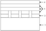
- Fig. 1is a schematic structural diagram of an ultrasonic transducer provided by an embodiment of the present application. As shown in Fig. 1, the ultrasonic transducer at least includes: a backing 1, an active element layer 2, a matching layer 3, and a lens stacked in sequence Layer 4.
- the backing 1is used to absorb the sound waves transmitted in the direction of the back of the ultrasonic transducer or the reflected waves of the sound waves/echoes of the active element layer 2 to prevent interference to the result.
- the backing 1In ultrasound imaging, the echo signal from the front is useful, and the signal from the back direction is an interference wave that needs to be eliminated. Therefore, the backing 1 needs to be designed as a sound-absorbing medium, so that the sound energy radiated backward is almost completely consumed.
- the selection of the backing 1is determined according to the specifications of the ultrasonic transducer, and its acoustic impedance and sound absorption performance will directly affect the technical indexes of the ultrasonic transducer, such as bandwidth and sensitivity.
- the backing 1is a sound-absorbing material with an acoustic impedance lower than the second threshold.
- the sound-absorbing materialincludes epoxy resin, glass microbeads and tungsten powder.
- the acoustic impedance of the backingis 2.5 Mrayl
- the corresponding acoustic attenuationis 14.6 decibels (dB) per millimeter when the frequency of the acoustic signal is 3MHz.
- the second thresholdis determined according to the sound absorption index of the ultrasonic transducer.
- the second thresholdmay be 3Mrayl, 2.8Mrayl, etc., and this embodiment does not limit the value of the second threshold.
- the active element layer 2is the core component of the ultrasonic transducer, and its functions include at least the following: 1. Obtaining large spatial gain or improving spatial resolution; 2. Increasing the emitted sound power, frequency band or improving transient characteristics; 3. , Improve the signal-to-noise ratio; 4. Realize multi-beam, beam scanning, variable focal length or dynamic focus, adaptive beamforming, etc., that is, form the required directivity.
- the impedance value of the active element layer 2is lower than the first threshold value.
- the value of the first thresholdis set according to the index of the ultrasonic transducer.
- the first thresholdmay be 25Mray1, 28Mray1, etc., and this embodiment does not limit the value of the first threshold.
- the value of the first thresholdmakes the impedance value of the active element layer 2 lower. Schematically, the impedance value of the active element layer is 20 Mrayl.
- the active element layer 2is a piezoelectric composite material.
- Piezoelectric composite materialshave the characteristics of low characteristic impedance and large electromechanical coupling coefficient.
- piezoelectric composite materialsinclude but are not limited to: 2-2 type, 1-3 type and other piezoelectric composite materials.
- the active element layer 2may be a single crystal material, a single crystal composite material or a piezoelectric thin film material, and the material type of the active element layer 2 is not limited in this embodiment.
- the matching layer 3is used to match the acoustic resistance difference between the active element layer 2 and the measured material.
- the matching layer 3includes n layers. Different matching layers have different impedance values, and the impedance value of the matching layer decreases layer by layer.
- the impedance value of the active element layer 2is greater than the impedance value of each matching layer; n is greater than 1. Integer.
- the value of nis 3 as an example for description. In actual implementation, the value of n may be larger or smaller, which is not limited in this embodiment.
- each matching layer 3is designed based on the principle of quarter-wavelength impedance matching.
- the first matching layerrefers to a matching layer close to the active element layer 2
- the nth matching layerrefers to a matching layer close to the lens layer 4 (that is, a matching layer away from the active element layer 2).
- n3
- impedance value of the 3-layer matching layersatisfies the following formula:
- Z m1is the impedance value of the first matching layer
- Z m2is the impedance value of the second matching layer
- Z m3is the impedance value of the third matching layer
- Z pis the impedance value of the active element layer
- Z Lis the impedance value of the load.
- the first matching layeris made of the first material with the first impedance value (such as 9.56 Mrayl), the first matching layer realizes the impedance value of the active element layer 2 and the impedance of the second matching layer
- the second matching layeris made of the second material with the second impedance value (such as: 4.7Mrayl), which realizes the impedance value of the first matching layer and the impedance value of the third matching layer
- the transition between the third layer of matching layeris made of a third material with a third impedance value (such as 2.16 Mrayl) to achieve the transition between the impedance value of the second layer of matching layer and the impedance value of the lens layer.
- the lens layer 4is used to focus the sound field.
- the ultrasonic transduceris made by bonding the active element layer 2 with the backing 1 and the m-layer matching layer 3; after cutting the bonded layer material, it is combined with the nm-layer matching layer 3. It is obtained by bonding and caulking, and m is a natural number smaller than n.
- the value of mis determined according to the leakage exposure of the cutter blade.
- the value of mis positively correlated with the amount of exposure.
- mcan take values such as 0, 1, 2 and so on.
- the ultrasonic transducers in the present applicationinclude but are not limited to the following types of planar transducers: linear array transducers, phased array transducers, single element transducers, etc.
- the ultrasonic transducerprovided by the present application includes a backing, an active element layer, a matching layer, and a lens layer stacked in sequence;
- the matching layerincludes n layers, and the impedance values of different matching layers are different, and the impedance of the matching layer The value decreases layer by layer, and the impedance value of the active element layer is greater than the impedance value of each matching layer; it can solve the problem that the existing ultrasonic transducer design does not disclose the design of the matching layer; it provides a matching layer design Solution, when the ultrasonic wave generated by the active element layer is transmitted to the object to be detected through the matching layer with a small acoustic impedance change, the sensitivity and bandwidth of the ultrasonic transducer are increased.
- the active component layeris bonded with the backing and the m-layer matching layer; the bonded layer material is cut and then bonded with the nm-layer matching layer and filled to obtain ultrasonic replacement.
- the energy devicecan improve the flexibility of the cutting method in the manufacturing process of the ultrasonic transducer.
- FIG. 2is a flowchart of a method for manufacturing an ultrasonic transducer according to an embodiment of the present application.
- the methodis used for manufacturing the above-mentioned ultrasonic transducer as an example for description.
- the methodincludes at least the following steps:
- Step 201Obtain the materials of the backing and the matching layer.
- Step 202bonding the active element layer with the backing and the m-layer matching layer, where m is a natural number smaller than n.
- the value of mis determined according to the leakage exposure of the cutter blade.
- Step 203Use a cutting machine to cut the bonded layer material and bond it with the n-m layer matching layer and fill the gap.
- the active element layerAfter bonding with the backing, a cutting machine is used to cut the bonded layer material; then, the cut layer material and the n-layer matching layer are sequentially bonded and caulked.
- the leakage of the dicing machine bladeis greater than or equal to the thickness of the active element layer, backing and first matching layer superimposed, and less than the active element layer, backing, first matching layer and second
- the thickness of the layer matching layeris superimposed, after bonding the active component layer to the backing and the first matching layer, use a cutting machine to cut the bonded layer material; then, combine the cut layer material with n- One layer of matching layer is bonded and filled in sequence.
- the leakage of the cutting machine bladeis greater than or equal to the thickness of the active component layer, backing, first matching layer and second matching layer superimposed, and less than the active component layer, backing, first When the thickness of the layer matching layer, the second layer matching layer and the third layer matching layer are superimposed, the active component layer is bonded to the backing, the first matching layer and the second matching layer, and then a cutting machine is used to bond the The latter layer material is cut; then, the cut layer material and the n-2 matching layer are sequentially bonded and filled.
- Step 204bonding the lens layer to the gap-filled layer material to obtain an ultrasonic transducer.
- the manufacturing method of the ultrasonic transducerobtains the materials of the backing and the matching layer; bonding the active element layer with the backing and the m-layer matching layer, where m is a natural number smaller than n ; Use a cutting machine to cut the bonded layer material and then bond it with the nm layer matching layer and fill the gap; bond the lens layer to the gap-filled layer material to obtain an ultrasonic transducer;
- the component layer, the backing and the m-layer matching layerare bonded in sequence and then cut, the problem of not being able to cut completely due to the limited leakage of the cutting knife; because the value of m can be adjusted as needed during the manufacturing process of the ultrasonic transducer Therefore, it is possible to cut only part of the material under the condition that the leakage of the cutting knife is limited, which can avoid the problem of incomplete cutting and improve cutting flexibility.
Landscapes
- Health & Medical Sciences (AREA)
- Life Sciences & Earth Sciences (AREA)
- Heart & Thoracic Surgery (AREA)
- Medical Informatics (AREA)
- Biophysics (AREA)
- Nuclear Medicine, Radiotherapy & Molecular Imaging (AREA)
- Pathology (AREA)
- Radiology & Medical Imaging (AREA)
- Engineering & Computer Science (AREA)
- Biomedical Technology (AREA)
- Gynecology & Obstetrics (AREA)
- Physics & Mathematics (AREA)
- Molecular Biology (AREA)
- Surgery (AREA)
- Animal Behavior & Ethology (AREA)
- General Health & Medical Sciences (AREA)
- Public Health (AREA)
- Veterinary Medicine (AREA)
- Ultra Sonic Daignosis Equipment (AREA)
- Transducers For Ultrasonic Waves (AREA)
Abstract
Description
Translated fromChinese本申请涉及一种超声换能器及超声换能器的制备方法,属于换能器技术领域。The application relates to an ultrasonic transducer and a preparation method of the ultrasonic transducer, and belongs to the technical field of transducers.
超声换能器发出的超声波进入人体组织后,在人体不同声特性阻抗的分界处形成反射回声,从而可以对人体内部组织器官成像,这就是医学超声换能器应用的原理。After the ultrasonic wave emitted by the ultrasonic transducer enters the human tissue, it forms a reflected echo at the boundary of different acoustic characteristic impedances of the human body, so that the internal tissues and organs of the human body can be imaged. This is the principle of the application of medical ultrasonic transducers.
申请号为201320296526.X公开了一种《相控阵换能器》,包括依次层叠的吸声材料层、压电元件层、匹配层、声头镜,在声头镜外面具有外壳,所述压电元件层是压电单晶材料制成,所述匹配层是由三层复合而成;在吸声材料层与压电元件层之间设有衬底层。The application number is 201320296526.X discloses a "phased array transducer", which includes a sound-absorbing material layer, a piezoelectric element layer, a matching layer, and an acoustic head lens stacked in sequence. A housing is provided on the outside of the acoustic head lens. The piezoelectric element layer is made of piezoelectric single crystal material, and the matching layer is composed of three layers; a substrate layer is provided between the sound-absorbing material layer and the piezoelectric element layer.
但是上述相控阵换能器未公开匹配层声阻抗的设置方式,而具有不同声阻抗的匹配层匹配压电材料与被测组织的声阻差异的能力是不同的,因此,需要提供一种匹配层的设计方案以更好地匹配压电材料与被测组织之间的声阻差异。However, the above-mentioned phased array transducer does not disclose the setting of the acoustic impedance of the matching layer, and the matching layer with different acoustic impedance has different ability to match the acoustic resistance difference between the piezoelectric material and the measured tissue. Therefore, it is necessary to provide a The design of the matching layer is to better match the acoustic resistance difference between the piezoelectric material and the measured tissue.
发明内容Summary of the invention
本申请提供了一种超声换能器及超声换能器的制备方法,可以解决现有的超声换能器设计方案未公开匹配层的设计方式的问题。本申请提供如下技术方案:The present application provides an ultrasonic transducer and a preparation method of the ultrasonic transducer, which can solve the problem that the design of the matching layer is not disclosed in the existing ultrasonic transducer design. This application provides the following technical solutions:
第一方面,提供了一种超声换能器,包括依次层叠的背衬、有源元件层、匹配层和透镜层;In a first aspect, an ultrasonic transducer is provided, which includes a backing, an active element layer, a matching layer, and a lens layer that are sequentially stacked;
所述匹配层包括n层,不同匹配层的阻抗值不同,且所述匹配层的阻抗值逐层减小,所述有源元件层的阻抗值大于各个匹配层的阻抗值;所述n为大于1的整数。The matching layer includes n layers, different matching layers have different impedance values, and the impedance value of the matching layer decreases layer by layer, and the impedance value of the active element layer is greater than the impedance value of each matching layer; the n is An integer greater than 1.
可选地,所述超声换能器是通过将所述有源元件层与所述背衬和m层匹配层粘接;对粘接后的层材料进行切割后与n-m层匹配层进行粘接并填缝得到的,所述m为小于所述n的自然数。Optionally, the ultrasonic transducer is made by bonding the active element layer with the backing and the m-layer matching layer; the bonded layer material is cut and then bonded with the nm-layer matching layer And obtained by caulking, the m is a natural number smaller than the n.
可选地,,所述n的值为3,3层匹配层的阻抗值满足下式:Optionally, the value of n is 3, and the impedance value of the 3-layer matching layer satisfies the following formula:


其中,Zm1为第一层匹配层的阻抗值;Zm2为第二层匹配层的阻抗值;Zm3为第三层匹配层的阻抗值;Zp为所述有源元件层的阻抗值;ZL为负载的阻抗值。Among them, Zm1 is the impedance value of the first matching layer; Zm2 is the impedance value of the second matching layer; Zm3 is the impedance value of the third matching layer; Zp is the impedance value of the active element layer ; ZL is the impedance value of the load.
可选地,,所述有源元件层的阻抗值低于第一阈值。Optionally, the impedance value of the active element layer is lower than the first threshold value.
可选地,,所述有源元件层的阻抗值为20兆瑞利;所述n为3,第一层匹配层的阻抗值为9.56兆瑞利、第二层匹配层的阻抗值为4.7兆瑞利、第三层匹配层的阻抗值为2.16兆瑞利。Optionally, the impedance value of the active element layer is 20 MegaRayles; the n is 3, the impedance value of the first matching layer is 9.56 MegaRayles, and the impedance value of the second matching layer is 4.7 The impedance value of Mega Rayleigh and the third matching layer is 2.16 Mega Rayleigh.
可选地,,所述背衬为声阻抗低于第二阈值的吸声材料。Optionally, the backing is a sound-absorbing material with an acoustic impedance lower than a second threshold.
可选地,,所述吸声材料包括环氧树脂、玻璃微珠和钨粉。Optionally, the sound-absorbing material includes epoxy resin, glass beads, and tungsten powder.
可选地,,所述背衬的声阻抗为2.5兆瑞利。Optionally, the acoustic impedance of the backing is 2.5 MegaRayles.
第二方面,提供了一种超声换能器的制作方法,用于制作第一方面提供的超声换能器,所述方法包括:In a second aspect, a manufacturing method of an ultrasonic transducer is provided, which is used to manufacture the ultrasonic transducer provided in the first aspect, and the method includes:
获取所述背衬和所述匹配层的材料;Obtaining materials of the backing and the matching layer;
将所述有源元件层与所述背衬和m层匹配层粘接,所述m为小于所述n的自然数;Bonding the active element layer with the backing and m-layer matching layer, where m is a natural number smaller than n;
使用切割机对粘接后的层材料进行切割后与n-m层匹配层进行粘接并填缝;Use a cutting machine to cut the bonded layer material and bond it with the n-m layer matching layer and fill the gap;
将透镜层粘接至填缝后的层材料,得到所述超声换能器。The lens layer is bonded to the gap-filled layer material to obtain the ultrasonic transducer.
可选地,所述m的取值根据所述切割机刀片的曝漏量确定。Optionally, the value of m is determined according to the leakage exposure of the cutter blade.
本申请的有益效果在于:超声换能器包括依次层叠的背衬、有源元件层、匹配层和透镜层;匹配层包括n层,不同匹配层的阻抗值不同,且匹配层的阻抗值逐层减小,有源元件层的阻抗值大于各个匹配层的阻抗值;可以解决现有 的超声换能器设计方案未公开匹配层的设计方式的问题;提供了一种匹配层的设计方案,当将由有源元件层生成的超声波通过具有小的声阻抗变化的匹配层传送至被检测的对象时,超声换能器的灵敏度和带宽增加。The beneficial effects of the present application are: the ultrasonic transducer includes a backing, an active element layer, a matching layer, and a lens layer that are stacked in sequence; the matching layer includes n layers, and the impedance values of different matching layers are different, and the impedance values of the matching layers gradually The layer is reduced, and the impedance value of the active element layer is greater than the impedance value of each matching layer; it can solve the problem that the existing ultrasonic transducer design does not disclose the design of the matching layer; it provides a matching layer design solution, When the ultrasonic waves generated by the active element layer are transmitted to the object to be detected through the matching layer with a small acoustic impedance change, the sensitivity and bandwidth of the ultrasonic transducer increase.
另外,通过根据实际情况选取切割深度,将有源元件层与背衬和m层匹配层粘接;对粘接后的层材料进行切割后与n-m层匹配层进行粘接并填缝得到超声换能器,可以提高超声换能器制作过程中切割方式的灵活性。In addition, by selecting the cutting depth according to the actual situation, the active component layer is bonded with the backing and the m-layer matching layer; the bonded layer material is cut and then bonded with the nm-layer matching layer and filled to obtain ultrasonic replacement. The energy device can improve the flexibility of the cutting method in the manufacturing process of the ultrasonic transducer.
上述说明仅是本申请技术方案的概述,为了能够更清楚了解本申请的技术手段,并可依照说明书的内容予以实施,以下以本申请的较佳实施例并配合附图详细说明如后。The above description is only an overview of the technical solutions of the present application. In order to understand the technical means of the present application more clearly and implement them according to the content of the description, the following detailed descriptions are given below with the preferred embodiments of the present application in conjunction with the accompanying drawings.
图1是本申请一个实施例提供的超声换能器的结构示意图;Fig. 1 is a schematic structural diagram of an ultrasonic transducer provided by an embodiment of the present application;
图2是本申请一个实施例提供的超声换能器的制作方法的流程图。Fig. 2 is a flowchart of a manufacturing method of an ultrasonic transducer provided by an embodiment of the present application.
下面结合附图和实施例,对本申请的具体实施方式作进一步详细描述。以下实施例用于说明本申请,但不用来限制本申请的范围。The specific implementation manners of the present application will be described in further detail below with reference to the accompanying drawings and embodiments. The following examples are used to illustrate the application, but are not used to limit the scope of the application.
图1是本申请一个实施例提供的超声换能器的结构示意图,如图1所示,该超声换能器至少包括:依次层叠的背衬1、有源元件层2、匹配层3和透镜层4。Fig. 1 is a schematic structural diagram of an ultrasonic transducer provided by an embodiment of the present application. As shown in Fig. 1, the ultrasonic transducer at least includes: a
背衬1用于吸收超声换能器背部方向传递的声波或有源元件层2声波/回波的反射波,以防止产生对结果的干扰。The
在超声成像中,来自前方的回波信号是有用的,来自背部方向的信号属于干扰波需要消除。因此,背衬1需要设计为吸声媒质,使向后辐射的声能几乎完全被消耗。背衬1的选取是根据超声换能器的指标而定的,它的声阻抗、吸声性能将直接影响超声换能器的技术指标,如频带宽度、灵敏度等。In ultrasound imaging, the echo signal from the front is useful, and the signal from the back direction is an interference wave that needs to be eliminated. Therefore, the
可选地,本实施例中,背衬1为声阻抗低于第二阈值的吸声材料。这样,可以保证背衬1的声阻抗较低,从而具有较强的吸声能力,具有较小的声衰减。 示意性地,吸声材料包括环氧树脂、玻璃微珠和钨粉,当然,还可以包括其它成分,通过预设比例配比得到。比如:背衬的声阻抗为2.5兆瑞利(Mrayl),对应的声衰减为在声信号的频率为3MHz时每毫米衰减14.6分贝(dB)。Optionally, in this embodiment, the
其中,第二阈值是根据超声换能器的吸声指标确定的,该第二阈值可以是3Mrayl、2.8Mrayl等,本实施例不对第二阈值的取值作限定。The second threshold is determined according to the sound absorption index of the ultrasonic transducer. The second threshold may be 3Mrayl, 2.8Mrayl, etc., and this embodiment does not limit the value of the second threshold.
有源元件层2为超声换能器核心部件,其作用至少包括以下几种:1、取得大的空间增益或提高空间分辨率;2、增大发射声功率、频带或改善瞬态特性;3、提高信噪比;4、实现多波束、波束扫描、可变焦距或动态聚焦、自适应波束成形等,即形成所需要的指向性。The
有源元件层2的阻抗值低于第一阈值。第一阈值的取值是根据超声换能器的指标设定的,第一阈值可以是25Mrayl、28Mrayl等,本实施例不对第一阈值的取值作限定。第一阈值的取值使得有源元件层2的阻抗值较低。示意性地,有源元件层的阻抗值为20Mrayl。The impedance value of the
可选地,有源元件层2为压电复合材料。压电复合材料具有特性阻抗低,机电耦合系数大等特点。示意性地,压电复合材料包括但不限于:2-2型,1-3型等压电复合材料。当然,有源元件层2可以是单晶材料、单晶复合材料或者压电薄膜材料,本实施例不对有源元件层2的材料类型作限定。Optionally, the
匹配层3用于匹配有源元件层2和被测材料之间的声阻差异。本申请中,匹配层3包括n层,不同匹配层的阻抗值不同,且匹配层的阻抗值逐层减小,有源元件层2的阻抗值大于各个匹配层的阻抗值;n为大于1的整数。图1中以n的取值为3为例进行说明,在实际实现时,n的取值可以更大或者更小,本实施例对此不作限定。The
各个匹配层3的阻抗基于四分之一波长阻抗匹配原理设计。The impedance of each
其中,第一层匹配层是指靠近有源元件层2的一层匹配层、第n层匹配层是指靠近透镜层4的一层匹配层(即远离有源元件层2的一层匹配层)。Among them, the first matching layer refers to a matching layer close to the
示意性地,n的值为3,此时,3层匹配层的阻抗值满足下式:Schematically, the value of n is 3. At this time, the impedance value of the 3-layer matching layer satisfies the following formula:


其中,Zm1为第一层匹配层的阻抗值;Zm2为第二层匹配层的阻抗值;Zm3为第三层匹配层的阻抗值;Zp为所述有源元件层的阻抗值;ZL为负载的阻抗值。Among them, Zm1 is the impedance value of the first matching layer; Zm2 is the impedance value of the second matching layer; Zm3 is the impedance value of the third matching layer; Zp is the impedance value of the active element layer ; ZL is the impedance value of the load.
比如:第一层匹配层由阻抗值为第一阻抗值(如:9.56Mrayl)的第一材料制成,第一层匹配层实现有源元件层2的阻抗值与第二层匹配层的阻抗值之间的过渡;第二层匹配层由阻抗值为第二阻抗值(如:4.7Mrayl)的第二材料制成,实现第一层匹配层的阻抗值与第三层匹配层的阻抗值之间的过渡;第三层匹配层由阻抗值为第三阻抗值(如2.16Mrayl)的第三材料制成,实现第二层匹配层的阻抗值与透镜层的阻抗值之间的过渡。For example: the first matching layer is made of the first material with the first impedance value (such as 9.56 Mrayl), the first matching layer realizes the impedance value of the
透镜层4用于对声场进行聚焦。The
可选地,本申请中,超声换能器是通过将有源元件层2与背衬1和m层匹配层3粘接;对粘接后的层材料进行切割后与n-m层匹配层3进行粘接并填缝得到的,m为小于n的自然数。Optionally, in this application, the ultrasonic transducer is made by bonding the
可选地,m的取值根据切割机刀片的曝漏量确定。m的取值与曝漏量呈正相关关系。根据曝漏量的不同,m可以取0、1、2等数值。Optionally, the value of m is determined according to the leakage exposure of the cutter blade. The value of m is positively correlated with the amount of exposure. Depending on the amount of exposure, m can take values such as 0, 1, 2 and so on.
可选地,本申请中的超声换能器包括但不限于下述几种平面换能器:线阵换能器、相控阵换能器、单个元件换能器等。Optionally, the ultrasonic transducers in the present application include but are not limited to the following types of planar transducers: linear array transducers, phased array transducers, single element transducers, etc.
综上所述,本申请提供的超声换能器包括依次层叠的背衬、有源元件层、匹配层和透镜层;匹配层包括n层,不同匹配层的阻抗值不同,且匹配层的阻抗值逐层减小,有源元件层的阻抗值大于各个匹配层的阻抗值;可以解决现有的超声换能器设计方案未公开匹配层的设计方式的问题;提供了一种匹配层的设计方案,当将由有源元件层生成的超声波通过具有小的声阻抗变化的匹配层传送至被检测的对象时,超声换能器的灵敏度和带宽增加。In summary, the ultrasonic transducer provided by the present application includes a backing, an active element layer, a matching layer, and a lens layer stacked in sequence; the matching layer includes n layers, and the impedance values of different matching layers are different, and the impedance of the matching layer The value decreases layer by layer, and the impedance value of the active element layer is greater than the impedance value of each matching layer; it can solve the problem that the existing ultrasonic transducer design does not disclose the design of the matching layer; it provides a matching layer design Solution, when the ultrasonic wave generated by the active element layer is transmitted to the object to be detected through the matching layer with a small acoustic impedance change, the sensitivity and bandwidth of the ultrasonic transducer are increased.
另外,通过根据实际情况选取切割深度,将有源元件层与背衬和m层匹配层粘接;对粘接后的层材料进行切割后与n-m层匹配层进行粘接并填缝得到超声换能器,可以提高超声换能器制作过程中切割方式的灵活性。In addition, by selecting the cutting depth according to the actual situation, the active component layer is bonded with the backing and the m-layer matching layer; the bonded layer material is cut and then bonded with the nm-layer matching layer and filled to obtain ultrasonic replacement. The energy device can improve the flexibility of the cutting method in the manufacturing process of the ultrasonic transducer.
图2是本申请一个实施例提供的一种超声换能器的制作方法的流程图,本实施例以该方法用于制作上述超声换能器为例进行说明。该方法至少包括以下几个步骤:FIG. 2 is a flowchart of a method for manufacturing an ultrasonic transducer according to an embodiment of the present application. In this embodiment, the method is used for manufacturing the above-mentioned ultrasonic transducer as an example for description. The method includes at least the following steps:
步骤201,获取背衬和匹配层的材料。Step 201: Obtain the materials of the backing and the matching layer.
步骤202,将有源元件层与背衬和m层匹配层粘接,m为小于n的自然数。
可选地,m的取值根据切割机刀片的曝漏量确定。Optionally, the value of m is determined according to the leakage exposure of the cutter blade.
步骤203,使用切割机对粘接后的层材料进行切割后与n-m层匹配层进行粘接并填缝。Step 203: Use a cutting machine to cut the bonded layer material and bond it with the n-m layer matching layer and fill the gap.
比如:在切割机刀片的曝漏量大于或等于有源元件层与背衬叠加后的厚度,且小于有源元件层、背衬与第一层匹配层叠加的厚度时,将有源元件层与背衬粘接后,使用切割机对粘接后的层材料进行切割;然后,将切割后的层材料与n层匹配层依次进行粘接并填缝。For example: when the leakage of the cutter blade is greater than or equal to the thickness of the active element layer and the backing layer, and less than the thickness of the active element layer, the backing and the first matching layer, the active element layer After bonding with the backing, a cutting machine is used to cut the bonded layer material; then, the cut layer material and the n-layer matching layer are sequentially bonded and caulked.
又比如:在切割机刀片的曝漏量大于或等于有源元件层、背衬和第一层匹配层叠加后的厚度,且小于有源元件层、背衬、第一层匹配层和第二层匹配层叠加的厚度时,将有源元件层与背衬和第一层匹配层粘接后,使用切割机对粘接后的层材料进行切割;然后,将切割后的层材料与n-1层匹配层依次进行粘接并填缝。Another example: the leakage of the dicing machine blade is greater than or equal to the thickness of the active element layer, backing and first matching layer superimposed, and less than the active element layer, backing, first matching layer and second When the thickness of the layer matching layer is superimposed, after bonding the active component layer to the backing and the first matching layer, use a cutting machine to cut the bonded layer material; then, combine the cut layer material with n- One layer of matching layer is bonded and filled in sequence.
再比如:在切割机刀片的曝漏量大于或等于有源元件层、背衬、第一层匹配层和第二层匹配层叠加后的厚度,且小于有源元件层、背衬、第一层匹配层、第二层匹配层和第三层匹配层叠加的厚度时,将有源元件层与背衬、第一层匹配层和第二层匹配层粘接后,使用切割机对粘接后的层材料进行切割;然后,将切割后的层材料与n-2层匹配层依次进行粘接并填缝。Another example: the leakage of the cutting machine blade is greater than or equal to the thickness of the active component layer, backing, first matching layer and second matching layer superimposed, and less than the active component layer, backing, first When the thickness of the layer matching layer, the second layer matching layer and the third layer matching layer are superimposed, the active component layer is bonded to the backing, the first matching layer and the second matching layer, and then a cutting machine is used to bond the The latter layer material is cut; then, the cut layer material and the n-2 matching layer are sequentially bonded and filled.
步骤204,将透镜层粘接至填缝后的层材料,得到超声换能器。
综上所述,本实施例提供的超声换能器的制作方法,通过获取背衬和匹配层的材料;将有源元件层与背衬和m层匹配层粘接,m为小于n的自然数;使用切割机对粘接后的层材料进行切割后与n-m层匹配层进行粘接并填缝;将透 镜层粘接至填缝后的层材料,得到超声换能器;可以解决将有源元件层、背衬和m层匹配层依次粘接后进行切割时,由于切割刀的曝漏量有限导致无法切割完全的问题;由于在超声换能器的制作过程中可以根据需要调整m的值,因此,可以在切割刀的曝漏量有限的情况下,只对部分层材料进行切割,可以避免切割不完全的问题,提高切割灵活性。In summary, the manufacturing method of the ultrasonic transducer provided by this embodiment obtains the materials of the backing and the matching layer; bonding the active element layer with the backing and the m-layer matching layer, where m is a natural number smaller than n ; Use a cutting machine to cut the bonded layer material and then bond it with the nm layer matching layer and fill the gap; bond the lens layer to the gap-filled layer material to obtain an ultrasonic transducer; When the component layer, the backing and the m-layer matching layer are bonded in sequence and then cut, the problem of not being able to cut completely due to the limited leakage of the cutting knife; because the value of m can be adjusted as needed during the manufacturing process of the ultrasonic transducer Therefore, it is possible to cut only part of the material under the condition that the leakage of the cutting knife is limited, which can avoid the problem of incomplete cutting and improve cutting flexibility.
以上所述实施例的各技术特征可以进行任意的组合,为使描述简洁,未对上述实施例中的各个技术特征所有可能的组合都进行描述,然而,只要这些技术特征的组合不存在矛盾,都应当认为是本说明书记载的范围。The technical features of the above-mentioned embodiments can be combined arbitrarily. In order to make the description concise, all possible combinations of the various technical features in the above-mentioned embodiments are not described. However, as long as there is no contradiction in the combination of these technical features, All should be considered as the scope of this specification.
以上所述实施例仅表达了本申请的几种实施方式,其描述较为具体和详细,但并不能因此而理解为对发明专利范围的限制。应当指出的是,对于本领域的普通技术人员来说,在不脱离本申请构思的前提下,还可以做出若干变形和改进,这些都属于本申请的保护范围。因此,本申请专利的保护范围应以所附权利要求为准。The above-mentioned embodiments only express several implementation manners of the present application, and their description is relatively specific and detailed, but they should not be understood as a limitation on the scope of the invention patent. It should be pointed out that for those of ordinary skill in the art, without departing from the concept of this application, several modifications and improvements can be made, and these all fall within the protection scope of this application. Therefore, the scope of protection of the patent of this application shall be subject to the appended claims.
Claims (10)
Translated fromChinese


Applications Claiming Priority (2)
| Application Number | Priority Date | Filing Date | Title |
|---|---|---|---|
| CN201911020505.3ACN110680390A (en) | 2019-10-25 | 2019-10-25 | Ultrasonic transducer and preparation method thereof |
| CN201911020505.3 | 2019-10-25 |
Publications (1)
| Publication Number | Publication Date |
|---|---|
| WO2021078291A1true WO2021078291A1 (en) | 2021-04-29 |
Family
ID=69113977
Family Applications (1)
| Application Number | Title | Priority Date | Filing Date |
|---|---|---|---|
| PCT/CN2020/123477CeasedWO2021078291A1 (en) | 2019-10-25 | 2020-10-24 | Ultrasonic transducer and method for manufacturing ultrasonic transducer |
Country Status (2)
| Country | Link |
|---|---|
| CN (1) | CN110680390A (en) |
| WO (1) | WO2021078291A1 (en) |
Families Citing this family (4)
| Publication number | Priority date | Publication date | Assignee | Title |
|---|---|---|---|---|
| CN110680390A (en)* | 2019-10-25 | 2020-01-14 | 飞依诺科技(苏州)有限公司 | Ultrasonic transducer and preparation method thereof |
| CN111687025A (en)* | 2020-06-17 | 2020-09-22 | 飞依诺科技(苏州)有限公司 | Double-backing ultrasonic transducer and preparation method thereof |
| CN112168201B (en)* | 2020-09-22 | 2024-01-30 | 飞依诺科技股份有限公司 | Preparation method of matching layer, matching layer and ultrasonic probe |
| CN119375363A (en)* | 2024-10-25 | 2025-01-28 | 北京通泰恒盛科技有限责任公司 | An acoustic emission sensor based on anti-reflection design and its preparation method |
Citations (7)
| Publication number | Priority date | Publication date | Assignee | Title |
|---|---|---|---|---|
| US20030032884A1 (en)* | 2001-07-05 | 2003-02-13 | General Electric Company | Ultrasound transducer for improving resolution in imaging system |
| CN1756955A (en)* | 2003-03-04 | 2006-04-05 | 茹瓦·皮尔斯·琼斯 | Apparatus and method with matched acoustic impedance |
| CN101238506A (en)* | 2005-08-08 | 2008-08-06 | 皇家飞利浦电子股份有限公司 | Wide-bandwidth matrix transducer with polyethylene third matching layer |
| CN101431941A (en)* | 2006-04-28 | 2009-05-13 | 松下电器产业株式会社 | Ultrasonic probe |
| CN101605288A (en)* | 2008-06-13 | 2009-12-16 | 上海爱培克电子科技有限公司 | A kind of acoustic impedance continually varying ultrasonic transducer |
| CN107534815A (en)* | 2015-02-24 | 2018-01-02 | 爱飞纽医疗机械贸易有限公司 | Ultrasonic transducer including matching layer with composite structure and manufacturing method thereof |
| CN110680390A (en)* | 2019-10-25 | 2020-01-14 | 飞依诺科技(苏州)有限公司 | Ultrasonic transducer and preparation method thereof |
Family Cites Families (3)
| Publication number | Priority date | Publication date | Assignee | Title |
|---|---|---|---|---|
| CN201261009Y (en)* | 2008-08-07 | 2009-06-24 | 上海爱培克电子科技有限公司 | Supersonic transducer with continuously changed acoustic impedance |
| WO2011014567A1 (en)* | 2009-07-29 | 2011-02-03 | Imacor Inc. | Ultrasound imaging transducer acoustic stack with integral electrical connections |
| JP5699690B2 (en)* | 2011-03-03 | 2015-04-15 | コニカミノルタ株式会社 | Manufacturing method of ultrasonic probe |
- 2019
- 2019-10-25CNCN201911020505.3Apatent/CN110680390A/enactivePending
- 2020
- 2020-10-24WOPCT/CN2020/123477patent/WO2021078291A1/ennot_activeCeased
Patent Citations (7)
| Publication number | Priority date | Publication date | Assignee | Title |
|---|---|---|---|---|
| US20030032884A1 (en)* | 2001-07-05 | 2003-02-13 | General Electric Company | Ultrasound transducer for improving resolution in imaging system |
| CN1756955A (en)* | 2003-03-04 | 2006-04-05 | 茹瓦·皮尔斯·琼斯 | Apparatus and method with matched acoustic impedance |
| CN101238506A (en)* | 2005-08-08 | 2008-08-06 | 皇家飞利浦电子股份有限公司 | Wide-bandwidth matrix transducer with polyethylene third matching layer |
| CN101431941A (en)* | 2006-04-28 | 2009-05-13 | 松下电器产业株式会社 | Ultrasonic probe |
| CN101605288A (en)* | 2008-06-13 | 2009-12-16 | 上海爱培克电子科技有限公司 | A kind of acoustic impedance continually varying ultrasonic transducer |
| CN107534815A (en)* | 2015-02-24 | 2018-01-02 | 爱飞纽医疗机械贸易有限公司 | Ultrasonic transducer including matching layer with composite structure and manufacturing method thereof |
| CN110680390A (en)* | 2019-10-25 | 2020-01-14 | 飞依诺科技(苏州)有限公司 | Ultrasonic transducer and preparation method thereof |
Also Published As
| Publication number | Publication date |
|---|---|
| CN110680390A (en) | 2020-01-14 |
Similar Documents
| Publication | Publication Date | Title |
|---|---|---|
| WO2021078291A1 (en) | Ultrasonic transducer and method for manufacturing ultrasonic transducer | |
| US6049159A (en) | Wideband acoustic transducer | |
| KR101477544B1 (en) | Ultrasonic transducer, ultrasonic probe, and ultrasound image diagnosis apparatus | |
| US11931203B2 (en) | Manufacturing method of a high frequency ultrasound transducer having an ultrasonic lens with integral central matching layer | |
| CN107534815B (en) | Ultrasonic transducer including matching layer with composite structure and method of making the same | |
| US20070197917A1 (en) | Continuous-focus ultrasound lens | |
| NO343671B1 (en) | Two frequency ultrasonic transducer arrays | |
| US10134973B2 (en) | Ultrasonic transducer and manufacture method thereof | |
| JP2007007262A (en) | Convex-type ultrasonic probe and ultrasonic diagnostic apparatus | |
| US20110208059A1 (en) | Ultrasound probe | |
| US11691177B2 (en) | Ultrasound probe with acoustic amplifier | |
| US9153767B2 (en) | Ultrasonic probe and manufacturing method thereof | |
| WO2012169568A1 (en) | Ultrasound probe | |
| JP4519330B2 (en) | Ultrasonic probe | |
| KR20130123347A (en) | Ultrasonic transducer, ultrasonic probe, and ultrasound image diagnosis apparatus | |
| KR101753492B1 (en) | The ultrasonic transducer having backing layer comprising materials having different acoustic impedances and method for manufacturing thereof | |
| TWI866710B (en) | Ultrasonic transducer array and ultrasonic probe | |
| KR20160096935A (en) | Ultrasonic Transducer for Improving Accoustic and Heat Characteristic | |
| US20210187549A1 (en) | Stressed-skin backing panel for image artifacts prevention | |
| JP2024070388A (en) | Manufacturing method of functionally designable piezoelectric material and manufacturing method of transducer using the same | |
| Bertora | Ultrasound transducers | |
| JPH0546217B2 (en) | ||
| Qian | Design of high frequency ultrasonic array transducers for medical imaging | |
| KR20160092072A (en) | Ultrasonic transducer having matching layer mixed oxide powder |
Legal Events
| Date | Code | Title | Description |
|---|---|---|---|
| 121 | Ep: the epo has been informed by wipo that ep was designated in this application | Ref document number:20879982 Country of ref document:EP Kind code of ref document:A1 | |
| NENP | Non-entry into the national phase | Ref country code:DE | |
| 122 | Ep: pct application non-entry in european phase | Ref document number:20879982 Country of ref document:EP Kind code of ref document:A1 | |
| 32PN | Ep: public notification in the ep bulletin as address of the adressee cannot be established | Free format text:NOTING OF LOSS OF RIGHTS PURSUANT TO RULE 112(1) EPC (EPO FORM 1205A DATED 19.06.2023) | |
| 122 | Ep: pct application non-entry in european phase | Ref document number:20879982 Country of ref document:EP Kind code of ref document:A1 |