WO2021053756A1 - Production method for semiconductor device, substrate-processing device, and program - Google Patents
Production method for semiconductor device, substrate-processing device, and programDownload PDFInfo
- Publication number
- WO2021053756A1 WO2021053756A1PCT/JP2019/036572JP2019036572WWO2021053756A1WO 2021053756 A1WO2021053756 A1WO 2021053756A1JP 2019036572 WJP2019036572 WJP 2019036572WWO 2021053756 A1WO2021053756 A1WO 2021053756A1
- Authority
- WO
- WIPO (PCT)
- Prior art keywords
- gas
- raw material
- material gas
- substrate
- semiconductor device
- Prior art date
- Legal status (The legal status is an assumption and is not a legal conclusion. Google has not performed a legal analysis and makes no representation as to the accuracy of the status listed.)
- Ceased
Links
Images


Classifications
- H—ELECTRICITY
- H01—ELECTRIC ELEMENTS
- H01L—SEMICONDUCTOR DEVICES NOT COVERED BY CLASS H10
- H01L21/00—Processes or apparatus adapted for the manufacture or treatment of semiconductor or solid state devices or of parts thereof
- H01L21/02—Manufacture or treatment of semiconductor devices or of parts thereof
- H01L21/02104—Forming layers
- H01L21/02107—Forming insulating materials on a substrate
- H01L21/02225—Forming insulating materials on a substrate characterised by the process for the formation of the insulating layer
- H01L21/0226—Forming insulating materials on a substrate characterised by the process for the formation of the insulating layer formation by a deposition process
- H01L21/02263—Forming insulating materials on a substrate characterised by the process for the formation of the insulating layer formation by a deposition process deposition from the gas or vapour phase
- H01L21/02271—Forming insulating materials on a substrate characterised by the process for the formation of the insulating layer formation by a deposition process deposition from the gas or vapour phase deposition by decomposition or reaction of gaseous or vapour phase compounds, i.e. chemical vapour deposition
- H01L21/0228—Forming insulating materials on a substrate characterised by the process for the formation of the insulating layer formation by a deposition process deposition from the gas or vapour phase deposition by decomposition or reaction of gaseous or vapour phase compounds, i.e. chemical vapour deposition deposition by cyclic CVD, e.g. ALD, ALE, pulsed CVD
- H—ELECTRICITY
- H01—ELECTRIC ELEMENTS
- H01L—SEMICONDUCTOR DEVICES NOT COVERED BY CLASS H10
- H01L21/00—Processes or apparatus adapted for the manufacture or treatment of semiconductor or solid state devices or of parts thereof
- H01L21/02—Manufacture or treatment of semiconductor devices or of parts thereof
- H01L21/02104—Forming layers
- H01L21/02107—Forming insulating materials on a substrate
- H01L21/02109—Forming insulating materials on a substrate characterised by the type of layer, e.g. type of material, porous/non-porous, pre-cursors, mixtures or laminates
- H01L21/022—Forming insulating materials on a substrate characterised by the type of layer, e.g. type of material, porous/non-porous, pre-cursors, mixtures or laminates the layer being a laminate, i.e. composed of sublayers, e.g. stacks of alternating high-k metal oxides
- C—CHEMISTRY; METALLURGY
- C23—COATING METALLIC MATERIAL; COATING MATERIAL WITH METALLIC MATERIAL; CHEMICAL SURFACE TREATMENT; DIFFUSION TREATMENT OF METALLIC MATERIAL; COATING BY VACUUM EVAPORATION, BY SPUTTERING, BY ION IMPLANTATION OR BY CHEMICAL VAPOUR DEPOSITION, IN GENERAL; INHIBITING CORROSION OF METALLIC MATERIAL OR INCRUSTATION IN GENERAL
- C23C—COATING METALLIC MATERIAL; COATING MATERIAL WITH METALLIC MATERIAL; SURFACE TREATMENT OF METALLIC MATERIAL BY DIFFUSION INTO THE SURFACE, BY CHEMICAL CONVERSION OR SUBSTITUTION; COATING BY VACUUM EVAPORATION, BY SPUTTERING, BY ION IMPLANTATION OR BY CHEMICAL VAPOUR DEPOSITION, IN GENERAL
- C23C16/00—Chemical coating by decomposition of gaseous compounds, without leaving reaction products of surface material in the coating, i.e. chemical vapour deposition [CVD] processes
- C23C16/22—Chemical coating by decomposition of gaseous compounds, without leaving reaction products of surface material in the coating, i.e. chemical vapour deposition [CVD] processes characterised by the deposition of inorganic material, other than metallic material
- C23C16/30—Deposition of compounds, mixtures or solid solutions, e.g. borides, carbides, nitrides
- C23C16/308—Oxynitrides
- C—CHEMISTRY; METALLURGY
- C23—COATING METALLIC MATERIAL; COATING MATERIAL WITH METALLIC MATERIAL; CHEMICAL SURFACE TREATMENT; DIFFUSION TREATMENT OF METALLIC MATERIAL; COATING BY VACUUM EVAPORATION, BY SPUTTERING, BY ION IMPLANTATION OR BY CHEMICAL VAPOUR DEPOSITION, IN GENERAL; INHIBITING CORROSION OF METALLIC MATERIAL OR INCRUSTATION IN GENERAL
- C23C—COATING METALLIC MATERIAL; COATING MATERIAL WITH METALLIC MATERIAL; SURFACE TREATMENT OF METALLIC MATERIAL BY DIFFUSION INTO THE SURFACE, BY CHEMICAL CONVERSION OR SUBSTITUTION; COATING BY VACUUM EVAPORATION, BY SPUTTERING, BY ION IMPLANTATION OR BY CHEMICAL VAPOUR DEPOSITION, IN GENERAL
- C23C16/00—Chemical coating by decomposition of gaseous compounds, without leaving reaction products of surface material in the coating, i.e. chemical vapour deposition [CVD] processes
- C23C16/22—Chemical coating by decomposition of gaseous compounds, without leaving reaction products of surface material in the coating, i.e. chemical vapour deposition [CVD] processes characterised by the deposition of inorganic material, other than metallic material
- C23C16/30—Deposition of compounds, mixtures or solid solutions, e.g. borides, carbides, nitrides
- C23C16/34—Nitrides
- C23C16/345—Silicon nitride
- C—CHEMISTRY; METALLURGY
- C23—COATING METALLIC MATERIAL; COATING MATERIAL WITH METALLIC MATERIAL; CHEMICAL SURFACE TREATMENT; DIFFUSION TREATMENT OF METALLIC MATERIAL; COATING BY VACUUM EVAPORATION, BY SPUTTERING, BY ION IMPLANTATION OR BY CHEMICAL VAPOUR DEPOSITION, IN GENERAL; INHIBITING CORROSION OF METALLIC MATERIAL OR INCRUSTATION IN GENERAL
- C23C—COATING METALLIC MATERIAL; COATING MATERIAL WITH METALLIC MATERIAL; SURFACE TREATMENT OF METALLIC MATERIAL BY DIFFUSION INTO THE SURFACE, BY CHEMICAL CONVERSION OR SUBSTITUTION; COATING BY VACUUM EVAPORATION, BY SPUTTERING, BY ION IMPLANTATION OR BY CHEMICAL VAPOUR DEPOSITION, IN GENERAL
- C23C16/00—Chemical coating by decomposition of gaseous compounds, without leaving reaction products of surface material in the coating, i.e. chemical vapour deposition [CVD] processes
- C23C16/22—Chemical coating by decomposition of gaseous compounds, without leaving reaction products of surface material in the coating, i.e. chemical vapour deposition [CVD] processes characterised by the deposition of inorganic material, other than metallic material
- C23C16/30—Deposition of compounds, mixtures or solid solutions, e.g. borides, carbides, nitrides
- C23C16/40—Oxides
- C23C16/401—Oxides containing silicon
- C—CHEMISTRY; METALLURGY
- C23—COATING METALLIC MATERIAL; COATING MATERIAL WITH METALLIC MATERIAL; CHEMICAL SURFACE TREATMENT; DIFFUSION TREATMENT OF METALLIC MATERIAL; COATING BY VACUUM EVAPORATION, BY SPUTTERING, BY ION IMPLANTATION OR BY CHEMICAL VAPOUR DEPOSITION, IN GENERAL; INHIBITING CORROSION OF METALLIC MATERIAL OR INCRUSTATION IN GENERAL
- C23C—COATING METALLIC MATERIAL; COATING MATERIAL WITH METALLIC MATERIAL; SURFACE TREATMENT OF METALLIC MATERIAL BY DIFFUSION INTO THE SURFACE, BY CHEMICAL CONVERSION OR SUBSTITUTION; COATING BY VACUUM EVAPORATION, BY SPUTTERING, BY ION IMPLANTATION OR BY CHEMICAL VAPOUR DEPOSITION, IN GENERAL
- C23C16/00—Chemical coating by decomposition of gaseous compounds, without leaving reaction products of surface material in the coating, i.e. chemical vapour deposition [CVD] processes
- C23C16/44—Chemical coating by decomposition of gaseous compounds, without leaving reaction products of surface material in the coating, i.e. chemical vapour deposition [CVD] processes characterised by the method of coating
- C23C16/455—Chemical coating by decomposition of gaseous compounds, without leaving reaction products of surface material in the coating, i.e. chemical vapour deposition [CVD] processes characterised by the method of coating characterised by the method used for introducing gases into reaction chamber or for modifying gas flows in reaction chamber
- C23C16/45523—Pulsed gas flow or change of composition over time
- C23C16/45525—Atomic layer deposition [ALD]
- C23C16/45527—Atomic layer deposition [ALD] characterized by the ALD cycle, e.g. different flows or temperatures during half-reactions, unusual pulsing sequence, use of precursor mixtures or auxiliary reactants or activations
- C—CHEMISTRY; METALLURGY
- C23—COATING METALLIC MATERIAL; COATING MATERIAL WITH METALLIC MATERIAL; CHEMICAL SURFACE TREATMENT; DIFFUSION TREATMENT OF METALLIC MATERIAL; COATING BY VACUUM EVAPORATION, BY SPUTTERING, BY ION IMPLANTATION OR BY CHEMICAL VAPOUR DEPOSITION, IN GENERAL; INHIBITING CORROSION OF METALLIC MATERIAL OR INCRUSTATION IN GENERAL
- C23C—COATING METALLIC MATERIAL; COATING MATERIAL WITH METALLIC MATERIAL; SURFACE TREATMENT OF METALLIC MATERIAL BY DIFFUSION INTO THE SURFACE, BY CHEMICAL CONVERSION OR SUBSTITUTION; COATING BY VACUUM EVAPORATION, BY SPUTTERING, BY ION IMPLANTATION OR BY CHEMICAL VAPOUR DEPOSITION, IN GENERAL
- C23C16/00—Chemical coating by decomposition of gaseous compounds, without leaving reaction products of surface material in the coating, i.e. chemical vapour deposition [CVD] processes
- C23C16/44—Chemical coating by decomposition of gaseous compounds, without leaving reaction products of surface material in the coating, i.e. chemical vapour deposition [CVD] processes characterised by the method of coating
- C23C16/455—Chemical coating by decomposition of gaseous compounds, without leaving reaction products of surface material in the coating, i.e. chemical vapour deposition [CVD] processes characterised by the method of coating characterised by the method used for introducing gases into reaction chamber or for modifying gas flows in reaction chamber
- C23C16/45523—Pulsed gas flow or change of composition over time
- C23C16/45525—Atomic layer deposition [ALD]
- C23C16/45553—Atomic layer deposition [ALD] characterized by the use of precursors specially adapted for ALD
- H—ELECTRICITY
- H01—ELECTRIC ELEMENTS
- H01L—SEMICONDUCTOR DEVICES NOT COVERED BY CLASS H10
- H01L21/00—Processes or apparatus adapted for the manufacture or treatment of semiconductor or solid state devices or of parts thereof
- H01L21/02—Manufacture or treatment of semiconductor devices or of parts thereof
- H01L21/02104—Forming layers
- H01L21/02107—Forming insulating materials on a substrate
- H01L21/02109—Forming insulating materials on a substrate characterised by the type of layer, e.g. type of material, porous/non-porous, pre-cursors, mixtures or laminates
- H01L21/02112—Forming insulating materials on a substrate characterised by the type of layer, e.g. type of material, porous/non-porous, pre-cursors, mixtures or laminates characterised by the material of the layer
- H01L21/02123—Forming insulating materials on a substrate characterised by the type of layer, e.g. type of material, porous/non-porous, pre-cursors, mixtures or laminates characterised by the material of the layer the material containing silicon
- H01L21/02126—Forming insulating materials on a substrate characterised by the type of layer, e.g. type of material, porous/non-porous, pre-cursors, mixtures or laminates characterised by the material of the layer the material containing silicon the material containing Si, O, and at least one of H, N, C, F, or other non-metal elements, e.g. SiOC, SiOC:H or SiONC
- H01L21/0214—Forming insulating materials on a substrate characterised by the type of layer, e.g. type of material, porous/non-porous, pre-cursors, mixtures or laminates characterised by the material of the layer the material containing silicon the material containing Si, O, and at least one of H, N, C, F, or other non-metal elements, e.g. SiOC, SiOC:H or SiONC the material being a silicon oxynitride, e.g. SiON or SiON:H
- H—ELECTRICITY
- H01—ELECTRIC ELEMENTS
- H01L—SEMICONDUCTOR DEVICES NOT COVERED BY CLASS H10
- H01L21/00—Processes or apparatus adapted for the manufacture or treatment of semiconductor or solid state devices or of parts thereof
- H01L21/02—Manufacture or treatment of semiconductor devices or of parts thereof
- H01L21/02104—Forming layers
- H01L21/02107—Forming insulating materials on a substrate
- H01L21/02109—Forming insulating materials on a substrate characterised by the type of layer, e.g. type of material, porous/non-porous, pre-cursors, mixtures or laminates
- H01L21/02112—Forming insulating materials on a substrate characterised by the type of layer, e.g. type of material, porous/non-porous, pre-cursors, mixtures or laminates characterised by the material of the layer
- H01L21/02123—Forming insulating materials on a substrate characterised by the type of layer, e.g. type of material, porous/non-porous, pre-cursors, mixtures or laminates characterised by the material of the layer the material containing silicon
- H01L21/02164—Forming insulating materials on a substrate characterised by the type of layer, e.g. type of material, porous/non-porous, pre-cursors, mixtures or laminates characterised by the material of the layer the material containing silicon the material being a silicon oxide, e.g. SiO2
- H—ELECTRICITY
- H01—ELECTRIC ELEMENTS
- H01L—SEMICONDUCTOR DEVICES NOT COVERED BY CLASS H10
- H01L21/00—Processes or apparatus adapted for the manufacture or treatment of semiconductor or solid state devices or of parts thereof
- H01L21/02—Manufacture or treatment of semiconductor devices or of parts thereof
- H01L21/02104—Forming layers
- H01L21/02107—Forming insulating materials on a substrate
- H01L21/02109—Forming insulating materials on a substrate characterised by the type of layer, e.g. type of material, porous/non-porous, pre-cursors, mixtures or laminates
- H01L21/02112—Forming insulating materials on a substrate characterised by the type of layer, e.g. type of material, porous/non-porous, pre-cursors, mixtures or laminates characterised by the material of the layer
- H01L21/02123—Forming insulating materials on a substrate characterised by the type of layer, e.g. type of material, porous/non-porous, pre-cursors, mixtures or laminates characterised by the material of the layer the material containing silicon
- H01L21/02167—Forming insulating materials on a substrate characterised by the type of layer, e.g. type of material, porous/non-porous, pre-cursors, mixtures or laminates characterised by the material of the layer the material containing silicon the material being a silicon carbide not containing oxygen, e.g. SiC, SiC:H or silicon carbonitrides
- H—ELECTRICITY
- H01—ELECTRIC ELEMENTS
- H01L—SEMICONDUCTOR DEVICES NOT COVERED BY CLASS H10
- H01L21/00—Processes or apparatus adapted for the manufacture or treatment of semiconductor or solid state devices or of parts thereof
- H01L21/02—Manufacture or treatment of semiconductor devices or of parts thereof
- H01L21/02104—Forming layers
- H01L21/02107—Forming insulating materials on a substrate
- H01L21/02109—Forming insulating materials on a substrate characterised by the type of layer, e.g. type of material, porous/non-porous, pre-cursors, mixtures or laminates
- H01L21/02112—Forming insulating materials on a substrate characterised by the type of layer, e.g. type of material, porous/non-porous, pre-cursors, mixtures or laminates characterised by the material of the layer
- H01L21/02123—Forming insulating materials on a substrate characterised by the type of layer, e.g. type of material, porous/non-porous, pre-cursors, mixtures or laminates characterised by the material of the layer the material containing silicon
- H01L21/0217—Forming insulating materials on a substrate characterised by the type of layer, e.g. type of material, porous/non-porous, pre-cursors, mixtures or laminates characterised by the material of the layer the material containing silicon the material being a silicon nitride not containing oxygen, e.g. SixNy or SixByNz
- H—ELECTRICITY
- H01—ELECTRIC ELEMENTS
- H01L—SEMICONDUCTOR DEVICES NOT COVERED BY CLASS H10
- H01L21/00—Processes or apparatus adapted for the manufacture or treatment of semiconductor or solid state devices or of parts thereof
- H01L21/02—Manufacture or treatment of semiconductor devices or of parts thereof
- H01L21/02104—Forming layers
- H01L21/02107—Forming insulating materials on a substrate
- H01L21/02109—Forming insulating materials on a substrate characterised by the type of layer, e.g. type of material, porous/non-porous, pre-cursors, mixtures or laminates
- H01L21/02205—Forming insulating materials on a substrate characterised by the type of layer, e.g. type of material, porous/non-porous, pre-cursors, mixtures or laminates the layer being characterised by the precursor material for deposition
- H01L21/02208—Forming insulating materials on a substrate characterised by the type of layer, e.g. type of material, porous/non-porous, pre-cursors, mixtures or laminates the layer being characterised by the precursor material for deposition the precursor containing a compound comprising Si
- H01L21/02211—Forming insulating materials on a substrate characterised by the type of layer, e.g. type of material, porous/non-porous, pre-cursors, mixtures or laminates the layer being characterised by the precursor material for deposition the precursor containing a compound comprising Si the compound being a silane, e.g. disilane, methylsilane or chlorosilane
- H—ELECTRICITY
- H01—ELECTRIC ELEMENTS
- H01L—SEMICONDUCTOR DEVICES NOT COVERED BY CLASS H10
- H01L21/00—Processes or apparatus adapted for the manufacture or treatment of semiconductor or solid state devices or of parts thereof
- H01L21/02—Manufacture or treatment of semiconductor devices or of parts thereof
- H01L21/02104—Forming layers
- H01L21/02107—Forming insulating materials on a substrate
- H01L21/02225—Forming insulating materials on a substrate characterised by the process for the formation of the insulating layer
- H01L21/0226—Forming insulating materials on a substrate characterised by the process for the formation of the insulating layer formation by a deposition process
- H01L21/02263—Forming insulating materials on a substrate characterised by the process for the formation of the insulating layer formation by a deposition process deposition from the gas or vapour phase
- H01L21/02271—Forming insulating materials on a substrate characterised by the process for the formation of the insulating layer formation by a deposition process deposition from the gas or vapour phase deposition by decomposition or reaction of gaseous or vapour phase compounds, i.e. chemical vapour deposition
- H—ELECTRICITY
- H01—ELECTRIC ELEMENTS
- H01L—SEMICONDUCTOR DEVICES NOT COVERED BY CLASS H10
- H01L21/00—Processes or apparatus adapted for the manufacture or treatment of semiconductor or solid state devices or of parts thereof
- H01L21/02—Manufacture or treatment of semiconductor devices or of parts thereof
- H01L21/02104—Forming layers
- H01L21/02107—Forming insulating materials on a substrate
- H01L21/02296—Forming insulating materials on a substrate characterised by the treatment performed before or after the formation of the layer
- H01L21/02299—Forming insulating materials on a substrate characterised by the treatment performed before or after the formation of the layer pre-treatment
- H01L21/02312—Forming insulating materials on a substrate characterised by the treatment performed before or after the formation of the layer pre-treatment treatment by exposure to a gas or vapour
- H—ELECTRICITY
- H01—ELECTRIC ELEMENTS
- H01L—SEMICONDUCTOR DEVICES NOT COVERED BY CLASS H10
- H01L21/00—Processes or apparatus adapted for the manufacture or treatment of semiconductor or solid state devices or of parts thereof
- H01L21/67—Apparatus specially adapted for handling semiconductor or electric solid state devices during manufacture or treatment thereof; Apparatus specially adapted for handling wafers during manufacture or treatment of semiconductor or electric solid state devices or components ; Apparatus not specifically provided for elsewhere
- H01L21/67005—Apparatus not specifically provided for elsewhere
- H01L21/67011—Apparatus for manufacture or treatment
- H01L21/67017—Apparatus for fluid treatment
Definitions
- This disclosurerelates to a semiconductor device manufacturing method, a substrate processing device, and a program.
- a process of forming a film on a substratemay be performed (see, for example, Patent Documents 1 and 2).
- An object of the present disclosureis to provide a technique capable of improving the characteristics of a film formed on a substrate.
- a step of supplying a first raw material gas containing a first element to a substrate in a processing chamberand
- (A)is a partially enlarged view of the surface of the substrate after the first raw material gas is supplied by performing step a
- (b)is a second step b after performing step a. 2
- (c)is the portion of the surface of the substrate after the reaction gas is supplied by performing step c after performing step b.
- the processing furnace 202has a heater 207 as a heating mechanism (temperature adjusting unit).
- the heater 207has a cylindrical shape and is vertically installed by being supported by a holding plate.
- the heater 207also functions as an activation mechanism (excitation portion) for activating (exciting) the gas with heat.
- a reaction tube 203is arranged concentrically with the heater 207.
- the reaction tube 203is made of a heat-resistant material such as quartz (SiO 2 ) or silicon carbide (SiC), and is formed in a cylindrical shape with the upper end closed and the lower end open.
- a processing chamber 201is formed in the hollow portion of the reaction tube 203.
- the processing chamber 201is configured to accommodate the wafer 200 as a substrate.
- the wafer 200is processed in the processing chamber 201.
- Nozzles 249a and 249bare provided in the processing chamber 201 so as to penetrate the lower side wall of the reaction tube 203.
- Gas supply pipes 232a and 232bare connected to the nozzles 249a and 249b, respectively.
- the gas supply pipes 232a and 232bare provided with mass flow controllers (MFCs) 241a and 241b which are flow rate controllers (flow control units) and valves 243a and 243b which are on-off valves, respectively, in order from the upstream side of the gas flow. ..
- MFCsmass flow controllers
- a gas supply pipe 232cis connected to the downstream side of the gas supply pipe 232a with respect to the valve 243a.
- the gas supply pipe 232cis provided with an MFC 241c and a valve 243c in this order from the upstream side of the gas flow.
- Gas supply pipes 232e and 232dare connected to the downstream side of the valves 243a and 243b of the gas supply pipes 232a and 232b, respectively.
- the gas supply pipes 232e and 232dare provided with MFC 241e and 241d and valves 243e and 243d, respectively, in this order from the upstream side of the gas flow.
- the nozzles 249a and 249bare arranged in an annular space in a plan view between the inner wall of the reaction tube 203 and the wafer 200, along the upper part of the inner wall of the reaction tube 203 from the lower part of the wafer 200. Each is provided so as to stand upward in the arrangement direction. That is, the nozzles 249a and 249b are provided along the wafer arrangement region in the region horizontally surrounding the wafer arrangement region on the side of the wafer arrangement region in which the wafer 200 is arranged. Gas supply holes 250a and 250b for supplying gas are provided on the side surfaces of the nozzles 249a and 249b, respectively.
- the gas supply holes 250a and 250bare opened so as to face the center of the reaction tube 203, respectively, so that gas can be supplied toward the wafer 200.
- a plurality of gas supply holes 250a and 250bare provided from the lower part to the upper part of the reaction tube 203.
- the first raw material gas containing the first elementfor example, a halosilane gas containing silicon (Si) as the first element and a halogen element is passed through the MFC 241a, the valve 243a, and the nozzle 249a. It is supplied into the processing chamber 201.
- the raw material gasis a raw material in a gaseous state, for example, a gas obtained by vaporizing a raw material in a liquid state under normal temperature and pressure, a raw material in a gaseous state under normal temperature and pressure, and the like.
- Halosilaneis a silane having a halogen group.
- the halogen groupincludes a chloro group, a fluoro group, a bromo group, an iodine group and the like. That is, the halogen group contains halogen elements such as chlorine (Cl), fluorine (F), bromine (Br) and iodine (I).
- halogen elementssuch as chlorine (Cl), fluorine (F), bromine (Br) and iodine (I).
- the halosilane-based gasfor example, a raw material gas containing Si and Cl, that is, a chlorosilane-based gas can be used.
- a chlorosilane-based gas in which the number of Si atoms contained in one molecule is one, for example, a tetrachlorosilane (SiCl 4 ) gascan be used.
- the SiCl 4 gasacts as a Si source in the film forming process described later.
- the temperature at which the first raw material gas thermally decomposesmay be referred to as the first temperature.
- First temperature using a SiCl 4 gas as the first source gasis a predetermined temperature within the range of more than 800 ° C..
- a halosilane gas containing Si as the first element and a halogen elementis MFC241c.
- a halosilane gas containing Si as the first element and a halogen elementis MFC241c.
- a chlorosilane-based gas having two or more Si atoms contained in one molecule and having a Si—Si bondfor example, hexachlorodisilane (Si 2 Cl 6 , abbreviated as HCDS) gas is used.
- HCDShexachlorodisilane
- the Si 2 Cl 6 gasacts as a Si source in the film forming process described later.
- the temperature at which the second raw material gas thermally decomposesmay be referred to as the second temperature.
- the second temperature when Si 2 Cl 6 gas is used as the second raw material gasis a predetermined temperature within the range of 500 ° C. or higher.
- a reaction gas containing a second element different from the first elementfor example, a nitride gas containing nitrogen (N) as the second element is processed via the MFC 241b, the valve 243b, and the nozzle 249b. It is supplied into the room 201.
- a nitride gas containing nitrogen (N) as the second elementis processed via the MFC 241b, the valve 243b, and the nozzle 249b. It is supplied into the room 201.
- the nitriding gasfor example, ammonia (NH 3 ) gas can be used.
- the NH 3 gasacts as an N source in the film forming process described later.
- nitrogen (N 2 ) gasas an inert gas is introduced into the processing chamber 201 via the MFC 241d, 241e, valves 243d, 243e, gas supply pipes 232a, 232b, nozzles 249a, 249b, respectively. Is supplied to.
- the N 2 gasacts as a purge gas, a carrier gas, a diluting gas, and the like.
- the first raw material gas supply systemis mainly composed of the gas supply pipe 232a, the MFC 241a, and the valve 243a.
- the second raw material gas supply systemis mainly composed of the gas supply pipe 232c, the MFC 241c, and the valve 243c.
- the reaction gas supply systemis mainly composed of the gas supply pipe 232b, the MFC 241b, and the valve 243b.
- the gas supply pipes 232d, 232e, MFC241d, 241e, and valves 243d, 243econstitute an inert gas supply system.
- any or all of the supply systemsmay be configured as an integrated supply system 248 in which valves 243a to 243e, MFC 241a to 241e, and the like are integrated.
- the integrated supply system 248is connected to each of the gas supply pipes 232a to 232e, and supplies various gases into the gas supply pipes 232a to 232e, that is, the opening / closing operation of the valves 243a to 243e and the MFC 241a to 241e.
- the flow rate adjustment operation and the likeare configured to be controlled by the controller 121 described later.
- the integrated supply system 248is configured as an integrated or divided integrated unit, and can be attached to and detached from the gas supply pipes 232a to 232e in units of the integrated unit. It is configured so that maintenance, replacement, expansion, etc. can be performed on an integrated unit basis.
- An exhaust pipe 231 that exhausts the atmosphere in the processing chamber 201is connected below the side wall of the reaction pipe 203.
- the exhaust pipe 231is provided via a pressure sensor 245 as a pressure detector (pressure detector) for detecting the pressure in the processing chamber 201 and an APC (Auto Pressure Controller) valve 244 as a pressure regulator (pressure regulator).
- a vacuum pump 246as a vacuum exhaust device is connected.
- the APC valve 244can perform vacuum exhaust and vacuum exhaust stop in the processing chamber 201 by opening and closing the valve with the vacuum pump 246 operating, and further, with the vacuum pump 246 operating, the APC valve 244 can perform vacuum exhaust and vacuum exhaust stop. By adjusting the valve opening degree based on the pressure information detected by the pressure sensor 245, the pressure in the processing chamber 201 can be adjusted.
- the exhaust systemis mainly composed of an exhaust pipe 231, a pressure sensor 245, and an APC valve 244.
- the vacuum pump 246may be included in the exhaust system.
- a seal cap 219is provided as a furnace palate body that can airtightly close the lower end opening of the reaction tube 203.
- the seal cap 219is made of a metal material such as SUS and is formed in a disk shape.
- An O-ring 220 as a sealing member that comes into contact with the lower end of the reaction tube 203is provided on the upper surface of the seal cap 219.
- a rotation mechanism 267 for rotating the boat 217which will be described later, is installed below the seal cap 219.
- the rotation shaft 255 of the rotation mechanism 267penetrates the seal cap 219 and is connected to the boat 217.
- the rotation mechanism 267is configured to rotate the wafer 200 by rotating the boat 217.
- the seal cap 219is configured to be vertically lifted and lowered by a boat elevator 115 as a lifting mechanism installed outside the reaction tube 203.
- the boat elevator 115is configured as a transport device (convey mechanism) for loading and unloading (conveying) the wafer 200 into and out of the processing chamber 201 by raising and lowering the seal cap 219.
- the boat 217 as a substrate supportsupports a plurality of wafers, for example 25 to 200 wafers, in a horizontal position and vertically aligned with each other, that is, in a multi-stage manner. It is configured to be arranged at intervals.
- the boat 217is made of a heat-resistant material such as quartz or SiC.
- a heat insulating plate 218 made of a heat-resistant material such as quartz or SiCis supported in a horizontal posture in multiple stages.
- a temperature sensor 263 as a temperature detectoris installed in the reaction tube 203. By adjusting the degree of energization of the heater 207 based on the temperature information detected by the temperature sensor 263, the temperature in the processing chamber 201 becomes a desired temperature distribution.
- the temperature sensor 263is provided along the inner wall of the reaction tube 203.
- the controller 121which is a control unit (control means), is configured as a computer including a CPU (Central Processing Unit) 121a, a RAM (Random Access Memory) 121b, a storage device 121c, and an I / O port 121d.
- the RAM 121b, the storage device 121c, and the I / O port 121dare configured so that data can be exchanged with the CPU 121a via the internal bus 121e.
- An input / output device 122configured as, for example, a touch panel is connected to the controller 121.
- the storage device 121cis composed of, for example, a flash memory, an HDD (Hard Disk Drive), or the like.
- a control program for controlling the operation of the substrate processing device, a process recipe in which the procedure and conditions of the film forming process described later are described, and the likeare readablely stored.
- the process recipesare combined so that the controller 121 can execute each procedure in the film forming process described later and obtain a predetermined result, and functions as a program.
- process recipes, control programs, etc.are collectively referred to simply as programs.
- a process recipeis also simply referred to as a recipe.
- the RAM 121bis configured as a memory area (work area) in which programs, data, and the like read by the CPU 121a are temporarily held.
- the I / O port 121dis connected to the above-mentioned MFC 241a to 241e, valves 243a to 243e, pressure sensor 245, APC valve 244, vacuum pump 246, temperature sensor 263, heater 207, rotation mechanism 267, boat elevator 115 and the like. ..
- the CPU 121ais configured to read and execute a control program from the storage device 121c and read a recipe from the storage device 121c in response to an input of an operation command from the input / output device 122 or the like.
- the CPU 121aadjusts the flow rate of various gases by the MFCs 241a to 241e, opens and closes the valves 243a to 243e, opens and closes the APC valve 244, and adjusts the pressure by the APC valve 244 based on the pressure sensor 245 so as to follow the contents of the read recipe.
- the controller 121can be configured by installing the above-mentioned program stored in the external storage device 123 on the computer.
- the external storage device 123includes, for example, a magnetic disk such as an HDD, an optical disk such as a CD, a magneto-optical disk such as MO, a semiconductor memory such as a USB memory, and the like.
- the storage device 121c and the external storage device 123are configured as a computer-readable recording medium. Hereinafter, these are collectively referred to simply as a recording medium.
- recording mediummay include only the storage device 121c alone, it may include only the external storage device 123 alone, or it may include both of them.
- the programmay be provided to the computer by using a communication means such as the Internet or a dedicated line without using the external storage device 123.
- FIG. 4shows an example of a substrate processing sequence for forming a film on a wafer 200 as a substrate, that is, an example of a film forming sequence, as one step of a manufacturing process of a semiconductor device using the above-mentioned substrate processing apparatus.
- FIG. 5 and FIG. 7will be described. In the following description, the operation of each part constituting the substrate processing apparatus is controlled by the controller 121.
- step asupplying SiCl 4 gas as the first source gas to the wafer 200 in the process chamber 201
- step bof supplying Si 2 Cl 6 gas as the second raw material gas to the wafer 200
- step cwhich supplies NH 3 gas as a reaction gas to the wafer 200
- SiN filmis formed on the wafer 200 as a film containing Si and N by performing the cycle of performing the above steps in this order a predetermined number of times (n times, n is an integer of 1 or more).
- steps a, b, and care represented as a, b, and c, respectively.
- FIGS. 4 and 5the film formation sequence shown in FIGS. 4 and 5 may be shown as follows for convenience. The same notation is used in the following description of other aspects and the like.
- waferWhen the word “wafer” is used in the present specification, it may mean the wafer itself or a laminate of a wafer and a predetermined layer or film formed on the surface thereof.
- wafer surfaceWhen the term “wafer surface” is used in the present specification, it may mean the surface of the wafer itself or the surface of a predetermined layer or the like formed on the wafer.
- a predetermined layerwhen it is described that "a predetermined layer is formed on a wafer”, it means that a predetermined layer is directly formed on the surface of the wafer itself, or a layer formed on the wafer or the like. It may mean forming a predetermined layer on top of it.
- boardin the present specification is also synonymous with the use of the term "wafer”.
- a plurality of wafers 200are loaded (wafer charged) into the boat 217. After that, as shown in FIG. 1, the boat 217 supporting the plurality of wafers 200 is lifted by the boat elevator 115 and carried into the processing chamber 201 (boat load). In this state, the seal cap 219 is in a state of sealing the lower end of the reaction tube 203 via the O-ring 220.
- Vacuum exhaust(vacuum exhaust) is performed by the vacuum pump 246 so that the inside of the processing chamber 201, that is, the space where the wafer 200 exists, has a desired processing pressure (vacuum degree).
- the pressure in the processing chamber 201is measured by the pressure sensor 245, and the APC valve 244 is feedback-controlled based on the measured pressure information.
- the wafer 200 in the processing chamber 201is heated by the heater 207 so as to have a desired processing temperature (deposition temperature).
- the state of energization of the heater 207is feedback-controlled based on the temperature information detected by the temperature sensor 263 so that the inside of the processing chamber 201 has a desired temperature distribution.
- the rotation mechanism 267starts the rotation of the wafer 200.
- the operation of the vacuum pump 246, the heating and rotation of the wafer 200are all continued until at least the processing of the wafer 200 is completed.
- Step aIn this step, supplying the SiCl 4 gas to the wafer 200 in the process chamber 201. Specifically, by opening the valve 243a, flow SiCl 4 gas to the gas supply pipe 232a. The flow rate of the SiCl 4 gas is adjusted by the MFC 241a, is supplied into the processing chamber 201 via the nozzle 249a, and is exhausted from the exhaust pipe 231. At this time, SiCl 4 gas is supplied to the wafer 200. At the same time valve 243 d, open the 243 e, flowing N 2 gas gas supply pipe 232 d, into 232 e. The flow rate of the N 2 gas is adjusted by the MFC 241d and 241e. The flow-adjusted N 2 gas is supplied into the processing chamber 201 together with the SiC 4 gas, and is exhausted from the exhaust pipe 231.
- the processing conditions in this stepare SiCl 4 gas supply flow rate: 1 to 2000 sccm, preferably 100 to 1000 sccm N 2 gas supply flow rate (each gas supply pipe): 100 to 20000 sccm Each gas supply time: 10 to 300 seconds, preferably 30 to 120 seconds Processing temperature (temperature lower than the first temperature, preferably lower than the first temperature and higher than the second temperature): 400 to 800 ° C., Preferably 500 to 800 ° C, more preferably 600 to 750 ° C. Processing pressure: 1-2666 Pa, preferably 10-1333 Pa Is exemplified.
- the notation of a numerical range such as "400 to 800 ° C.” in the present specificationmeans that the lower limit value and the upper limit value are included in the range. Therefore, "400 to 800 ° C.” means “400 ° C. or higher and 800 ° C. or lower.” The same applies to other numerical ranges.
- preflow supplied to the wafer 200 prior to the reaction gas such as NH 3 gaspreflow supplied to the wafer 200 prior to the reaction gas such as NH 3 gas.
- the reaction gassuch as NH 3 gas.
- an adsorption site by hydrogen (H)is formed on the surface of the wafer 200, and in this step and step b described later, a state in which Si atoms are easily adsorbed (that is, that is, It is in a state of high reactivity with Si atom).
- the preflow procedurecan be performed, for example, in the same manner as in step c described later.
- SiCl bonds in SiCl 4it is possible to cut a portion of SiCl bonds in SiCl 4, to adsorb the Si which has become to have a dangling bond in the adsorption sites on the surface of the wafer 200. Further, under the conditions described above, it is possible to keep the SiCl bond was not cleaved in the SiCl 4. For example, of the four bonds of Si constituting SiCl 4, Si having unbonded hands is applied to the adsorption site on the surface of the wafer 200 in a state where Cl is bonded to each of the three bonds. Can be adsorbed.
- Siis formed on the wafer 200. It is possible to avoid multiple deposits.
- Cl separated from Siconstitutes a gaseous substance such as HCl or Cl 2 , and is exhausted from the exhaust pipe 231.
- Adsorption reaction of Siproceeds and adsorption sites remaining on the surface of the wafer 200 is eliminated, the adsorption reaction is made to saturate, in this step, stopping the supply of the SiCl 4 gas before the adsorption reaction is saturated However, it is desirable to end this step with the adsorption sites remaining.
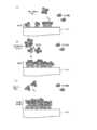
- FIG. 7Ashows a partially enlarged view of the surface of the wafer 200 on which the first layer is formed.
- a layer having a thickness of less than one atomic layermeans an atomic layer formed discontinuously, and a layer having a thickness of one atomic layer means an atomic layer formed continuously. It means that.
- the fact that the layer having a thickness of less than one atomic layer is substantially uniformmeans that atoms are adsorbed on the surface of the wafer 200 at a substantially uniform density. Since the first layer is formed on the wafer 200 to have a substantially uniform thickness, it is excellent in step coverage characteristics and wafer in-plane film thickness uniformity.
- the processing temperatureis less than 400 ° C.
- Simay be difficult to be adsorbed on the wafer 200, and it may be difficult to form the first layer.
- the first layercan be formed on the wafer 200.
- the treatment temperatureis set to 500 ° C. or higher, the above-mentioned effect can be surely obtained.
- the treatment temperatureis set to 600 ° C. or higher, the above-mentioned effects can be obtained more reliably.
- the valve 243ais closed to stop the supply of SiCl 4 gas into the processing chamber 201. Then, the inside of the processing chamber 201 is evacuated, and the gas or the like remaining in the processing chamber 201 is removed from the inside of the processing chamber 201. At this time, the valves 243d and 243e are left open to maintain the supply of the N 2 gas as the inert gas into the processing chamber 201.
- the N 2 gasacts as a purge gas, whereby the effect of removing the gas or the like remaining in the processing chamber 201 from the processing chamber 201 can be enhanced.
- the first raw material gasother SiCl 4 gas, dichlorosilane (SiH 2 Cl 2, abbreviation: DCS) gas, trichlorosilane (SiHCl 3, abbreviated: TCS) can be used halosilane material gas such as a gas.
- DCSdichlorosilane
- TCStrichlorosilane
- the inert gasin addition to the N 2 gas, a rare gas such as Ar gas, He gas, Ne gas, and Xe gas can be used. This point is the same in steps b and c described later.
- Step bSi 2 Cl 6 gas is supplied to the wafer 200 in the processing chamber 201, that is, the first layer formed on the wafer 200.
- the valve 243cis opened to allow Si 2 Cl 6 gas to flow into the gas supply pipe 232a.
- the flow rate of the Si 2 Cl 6 gasis controlled by the MFC 241c, is supplied into the processing chamber 201 via the nozzle 249a, and is exhausted from the exhaust pipe 231. At this time, Si 2 Cl 6 gas is supplied to the wafer 200.
- the processing conditions for this stepare Si 2 Cl 6 gas supply flow rate: 1 to 2000 sccm, preferably 100 to 1000 sccm Si 2 Cl 6 gas supply time: 0.5 to 60 seconds, preferably 1 to 30 seconds
- Processing temperaturetemperature higher than the second temperature, preferably higher than the second temperature and lower than the first temperature: 500-1000 ° C, preferably 600-800 ° C, more preferably 650-750 ° C Is exemplified.
- Other processing conditionsare the same as the processing conditions in step a.
- the Si having unbonded handsremained in the wafer in step a without the first layer being formed. It can be adsorbed on the surface of the wafer 200 by reacting with the adsorption sites on the surface of the 200.
- the Si-containing layer as the second layeris formed with a substantially uniform thickness based on the first layer formed to have a substantially uniform thickness.
- Sis having unbonded hands due to thermal decomposition of Si 2 Cl 6are bonded to each other to form a Si—Si bond.
- Si—Si bondsBy reacting these Si—Si bonds with the adsorption sites and the like remaining on the surface of the wafer 200, it is possible to include the Si—Si bonds in the second layer and to form a layer in which Si is multiple-deposited. .. That is, by this step, the amount of Si—Si bond contained in the second layer (content ratio) is made larger than the amount of Si—Si bond contained in the first layer (content ratio).
- Cl separated from Siconstitutes a gaseous substance such as HCl or Cl 2 , and is exhausted from the exhaust pipe 231.
- the thermal decomposition temperature of the second raw material gasIs preferably lower than the thermal decomposition temperature of the first raw material gas.
- the second source gasis a gas that is more likely to form a Si—Si bond under the same conditions than the first source gas.
- the molecule of the second raw material gascontains a Si—Si bond, and the composition ratio of Si to a halogen element such as Cl in the molecule of the second raw material gas is higher than that of the first raw material gas. Larger is preferable.
- the processing conditionssuch as the processing temperature of each step are selected and the first step is performed so that the Si—Si bond that reacts with the adsorption sites remaining on the wafer surface is more likely to be formed than in step a.
- One source gas and a second source gasare selected.
- a Si-containing layer having a substantially uniform thickness exceeding the thickness of the first layeris formed as the second layer.
- a Si-containing layer having a substantially uniform thickness exceeding one atomic layeris formed as the second layer.
- FIG. 7Bshows a partially enlarged view of the surface of the wafer 200 on which the second layer is formed.
- the second layermeans a Si-containing layer on the wafer 200 formed by performing steps a and b once.
- the treatment temperatureis less than 500 ° C., the Si 2 Cl 6 gas is less likely to be thermally decomposed, and the formation of the second layer may be difficult.
- the second layercan be formed on the first layer.
- the treatment temperatureis set to 600 ° C. or higher, the above-mentioned effect can be surely obtained.
- the treatment temperatureis 650 ° C. or higher, the above-mentioned effect can be obtained more reliably.
- the thermal decomposition of Si 2 Cl 6 gasbecomes excessive, and the deposition of non-self-saturating Si tends to proceed rapidly, so that it becomes difficult to form the second layer substantially uniformly.
- the treatment temperatureexceeds 1000 ° C.
- the thermal decomposition of Si 2 Cl 6 gasbecomes excessive, and the deposition of non-self-saturating Si tends to proceed rapidly, so that it becomes difficult to form the second layer substantially uniformly.
- the treatment temperatureBy setting the treatment temperature to 1000 ° C. or lower , excessive thermal decomposition of Si 2 Cl 6 gas is suppressed, and by controlling the deposition of Si that does not self-saturate, it is possible to form the second layer substantially uniformly.
- BecomeBy setting the treatment temperature to 800 ° C. or lower, the above-mentioned effect can be surely obtained.
- the treatment temperatureBy setting the treatment temperature to 750 ° C. or lower, the above-mentioned effect can be obtained more reliably.
- the temperature conditions in steps a and bare substantially the same. As a result, it is not necessary to change the temperature of the wafer 200 between steps a and b, that is, to change the temperature in the processing chamber 201 (change the set temperature of the heater 207). The waiting time until the temperature is stabilized is not required, and the throughput of substrate processing can be improved. Therefore, in both steps a and b, the temperature of the wafer 200 is preferably set to a predetermined temperature in the range of, for example, 500 to 800 ° C., preferably 600 to 800 ° C., more preferably 650 to 750 ° C.
- the thermal decomposition of the first raw material gasdoes not substantially occur (that is, is suppressed) in step a, and the second in step b.
- the temperature conditions and the first and second source gasesare selected so that thermal decomposition of the source gas occurs (ie, is promoted).
- the valve 243cis closed to stop the supply of Si 2 Cl 6 gas into the processing chamber 201. Then, the gas or the like remaining in the processing chamber 201 is removed from the processing chamber 201 by the same treatment procedure and treatment conditions as in the step of removing the residual gas in step a described above.
- silicon hydride-based raw material gassuch as monosilane (SiH 4 , abbreviation: MS) gas, trisdimethylaminosilane (Si [N (CH 3 ) 2 ] 3 H, Aminosilane-based raw material gas such as abbreviation: 3DMAS) gas and bisdiethylaminosilane (SiH 2 [N (C 2 H 5 ) 2 ] 2; abbreviation: BDEAS) gas can be used.
- a non-halogen gasas the second raw material gas, it is possible to avoid mixing of halogen into the SiN film finally formed on the wafer 200.
- Step cthe process chamber wafer 200 in 201, i.e., supplying the NH 3 gas to the layer of the first layer formed on the wafer 200 and the second layer is formed by laminating. Specifically, by opening the valve 243b, supplying the NH 3 gas into the gas supply pipe 232b. The flow rate of the NH 3 gas is controlled by the MFC 241b, is supplied into the processing chamber 201 via the nozzle 249b, and is exhausted from the exhaust pipe 231. At this time, NH 3 gas is supplied to the wafer 200.
- the processing conditions in this stepare NH 3 gas supply flow rate: 100 to 10000 sccm, preferably 1000 to 5000 sccm NH 3 Gas supply time: 1 to 120 seconds, preferably 10 to 60 seconds Processing pressure: 1 to 4000 Pa, preferably 10 to 1000 Pa Is exemplified.
- Other processing conditionsare the same as the processing conditions in step a.
- the temperature condition in step cis preferably the same as that in steps a and b from the viewpoint of improving the productivity of the film forming process, but may be different from these conditions.
- the second layercan be nitrided.
- Cl contained in the second layerconstitutes a gaseous substance such as HCl and Cl 2 , and is exhausted from the exhaust pipe 231.
- FIG. 7Cshows a partially enlarged view of the surface of the wafer 200 on which the third layer is formed.
- hydrogen nitride-based gassuch as diimide (N 2 H 2 ) gas, hydrazine (N 2 H 4 ) gas, and N 3 H 8 gas can be used in addition to NH 3 gas.
- a SiN film having a predetermined composition ratio and a predetermined film thicknessis formed on the wafer 200 by performing this cycle a predetermined number of times (n times, n is an integer of 1 or more). Can be done.
- the above cycleis preferably repeated a plurality of times. That is, it is preferable that the thickness of the SiN layer formed per cycle is made smaller than the desired film thickness, and the above cycle is repeated a plurality of times until the desired film thickness is reached.
- the gasis supplied from each of the gas supply pipes 232d and 232e into the N 2 gas treatment chamber 201 as an inert gas, and is exhausted from the exhaust pipe 231.
- the inside of the treatment chamber 201is purged, and the gas, reaction by-products, and the like remaining in the treatment chamber 201 are removed from the inside of the treatment chamber 201 (after-purge).
- the atmosphere in the treatment chamber 201is replaced with the inert gas (replacement of the inert gas), and the pressure in the treatment chamber 201 is restored to the normal pressure (return to atmospheric pressure).
- step asupplying SiCl 4 gas, from doing a step b for supplying Si 2 Cl 6 gas, both steps of, SiN is formed on the wafer 200 It is possible to achieve both the effect of improving the step coverage characteristics of the film and the uniformity of the film thickness in the wafer surface and the effect of increasing the film formation rate of this film.
- the thickness of the wafer 200is less than one atomic layer.
- a Si-containing layer (first layer) having a substantially uniform thicknessis formed. If it is assumed that the step a for supplying the SiCl 4 gas and the step c for supplying the NH 3 gas are performed in this order a predetermined number of times without performing the step b, the cycles are formed per cycle.
- the thickness of the Si-containing layeris uniform over the wafer surface, it is possible to improve the step coverage characteristics of the SiN film finally formed on the wafer 200 and the uniformity of the film thickness inside the wafer surface. .. On the other hand, since the thickness of the Si-containing layer formed per cycle is thin, it may be difficult to increase the film formation rate of the SiN film formed on the wafer 200.
- Si 2 Cl 6 gaswhich has a lower thermal decomposition temperature than SiC 4 gas and is easily thermally decomposed
- the wafer 200has a Si—Si bond.
- a Si-containing layer (second layer) having a thickness exceeding the atomic layerwill be formed.
- the cycle of supplying Si 2 Cl 6 gas and the step c of supplying NH 3 gas in this orderis performed a predetermined number of times without performing step a, it is formed per cycle. Since the thickness of the Si-containing layer to be formed is large, it is possible to improve the film formation rate of the SiN film finally formed on the wafer 200.
- the step coverage characteristics of the SiN film formed on the wafer 200 and the uniformity of the film thickness in the wafer surfaceMay be difficult to improve.
- both steps a and bsince both steps a and b are performed, it is possible to achieve both the effects obtained from each step. For example, by completing step a before the adsorption reaction of Si is saturated and shifting to step b having a relatively high film formation rate, the film formation rate is improved as compared with the case where only step a is executed for the same time. Can be made to. Further, by forming the first layer having relatively excellent thickness uniformity in step a and then forming the second layer based on the first layer in step b, as compared with the case where only step b is executed. Therefore, the step coverage characteristics of the SiN film formed on the wafer 200 and the uniformity of the film thickness in the wafer surface can be improved.
- step ais performed before step b, and then step b is performed, so that the step coverage characteristics and the wafer surface of the SiN film finally formed on the wafer 200 are performed. It is possible to increase the film formation rate while sufficiently exhibiting the uniformity of the inner film thickness.
- step bSi containing a Si—Si bond generated by thermal decomposition is formed on the surface of the wafer 200. Since it tends to be adsorbed irregularly, a layer that tends to have a non-uniform thickness may be formed in the wafer surface as a base of the Si-containing film to be formed in step a. Therefore, the technical significance of step a of forming a Si-containing layer having a substantially uniform thickness during the film forming process is likely to be lost.
- step ais performed before step b, and then step b is performed, so that the thickness of the Si-containing film to be formed in step b is substantially uniform. It is possible to form a Si-containing layer. Therefore, the technical significance of step a of forming a Si-containing layer having a substantially uniform thickness in the middle of the film forming process can be fully exhibited.
- the ratio of Si—Si bondingcan be reduced to control the thickness of the second layer to be reduced.
- the composition ratio of the SiN film finally formed on the wafer 200can be controlled so that the composition ratio of Si becomes smaller. it can.
- the thickness of the second layeris reduced in the range of the thickness exceeding one atomic layer.
- the ratio of Si—Si bonds contained in the second layercan be increased, and the thickness of the second layer can be controlled in the direction of increasing the thickness.
- the composition ratio of the SiN film finally formed on the wafer 200can be controlled in the direction of increasing the composition ratio of Si. it can.
- the thickness of the second layeris increased in the range of the thickness exceeding one atomic layer.
- the composition ratio of Sican be controlled to be larger (that is, to be Si-rich) with respect to the composition ratio in the stoichiometric composition of the SiN film.
- the above-mentioned B / Ais, for example, adjusting the size of the ratio T B / T A of Si 2 Cl 6 gas supply time of T B per cycle for SiCl 4 feed time T A of the gas per cycle That is, it can be controlled by adjusting the supply time of SiCl 4 gas and Si 2 Cl 6 gas per cycle. Further, the above B / A can be controlled by adjusting the magnitude of the ratio F B / F A feed rate F B of Si 2 Cl 6 gas to the feed flow rate F A of SiCl 4 gas.
- the Si in the SiN film finally formed on the wafer 200is also formed.
- the composition ratiowhich is the ratio of the content of N to the content of N, can be controlled.
- the thickness of the second layercan be controlled to be reduced.
- the composition ratio of the SiN film finally formed on the wafer 200can be controlled so that the composition ratio of Si becomes smaller. it can.
- the pressure P Bby greater than the pressure P A in the processing chamber 201 at step a, can be controlled in a direction to increase the thickness of the second layer.
- the composition ratio of the SiN film finally formed on the wafer 200can be controlled in the direction of increasing the composition ratio of Si. it can.
- the treatment temperature in step ais set lower than the thermal decomposition temperature (first temperature) of the SiCl 4 gas, and the treatment temperature in step b is set to the thermal decomposition temperature (second temperature) of the Si 2 Cl 6 gas. Since it is made higher than, the above-mentioned effect can be surely obtained.
- step asince the lower temperature than the processing temperature first temperature, it is possible to suppress thermal decomposition of SiCl 4 gas, the step coverage of the SiN film that is finally formed on the wafer 200 It is possible to improve the characteristics and the uniformity of the film thickness inside the wafer surface. Further, it is possible to control the composition ratio of the SiN film in the direction of approaching Si 3 N 4.
- step bsince the processing temperature is set to a temperature higher than the second temperature , appropriate thermal decomposition of the Si 2 Cl 6 gas can be maintained, and a SiN film finally formed on the wafer 200 can be formed. It is possible to improve the membrane rate. Further, the composition ratio of the SiN film can be controlled in the direction of Si rich.
- Nis used as an example, although NH 3 gas as a reaction gas containing a second element is described as an example, the present disclosure is not limited thereto.
- oxygen (O)is used as the second element
- the reaction gas containing the second elementin addition to O 2 gas, ozone (O 3 ) gas, water vapor (H 2 O gas), O 2 + H 2 gas, one Nitric oxide (NO) gas, nitrous oxide (N 2 O) gas, nitrogen dioxide (NO 2) may be used such as gas.
- the reaction gasit may be used both of these O-containing gas and NH 3 gas as described above.
- a silicon oxide filmmay be formed on the wafer 200 by the film forming sequence shown below.
- a silicon oxynitride film(SiON film) may be formed on the wafer 200 by the film forming sequence shown below.
- the processing procedure and processing conditions in each step of these film formation sequencescan be, for example, the same processing procedures and processing conditions as those described above. In these cases as well, the same effects as those described above can be obtained.
- step bis started in a state where the supply of SiC 4 gas is continued, and Si 2 Cl 6 gas is supplied, and so on.
- step bis overlapped (see FIG. 6).
- processing procedure and processing conditions at this timecan be, for example, the same as the processing procedure and processing conditions of the above-described aspect.
- Sample 1was prepared by performing n cycles of step a and step c in this order without performing step b.
- Samples 2 to 5were prepared by performing n cycles of performing steps a to c in this order.
- Sample 1-5was a SiCl 4 gas supply time in step a and 60 seconds, respectively.
- the supply time of Si 2 Cl 6 gas in step bwas 1.5 seconds, 4.5 seconds, 9 seconds, and 18 seconds, respectively.
- the other treatment conditionswere common conditions within the treatment condition range in the above-described embodiment, including the number of cycles performed and the amount of gas supplied.
- the in-wafer average film thickness of the SiN film in Samples 2 to 5is thicker than the in-wafer average film thickness of the SiN film in Sample 1. That is, the case where both the SiC 4 gas and the Si 2 Cl 6 gas are supplied as the raw material gas is more than the case where only the SiCl 4 gas is supplied without supplying the Si 2 Cl 6 gas as the raw material gas. It can be seen that the amount of SiN film formed per cycle increases, that is, the film forming rate improves.
- the average film thickness of the SiN film in the wafer plane in the samples 2 to 5becomes thicker as the supply time of the Si 2 Cl 6 gas is lengthened.
- the amount of the SiN film formed per cycleincreases, that is, the film forming rate of the SiN film formed on the wafer 200 is improved. Understand.
- the refractive index of the SiN film in Samples 2 to 5is larger than the refractive index of the SiN film in Sample 1. That is, the case where both the SiC 4 gas and the Si 2 Cl 6 gas are supplied as the raw material gas is more than the case where only the SiCl 4 gas is supplied without supplying the Si 2 Cl 6 gas as the raw material gas. It can be seen that the refractive index of the SiN film increases.
- the refractive index of Si with respect to a wavelength of 633nm lightis more in the case of supplying both gas SiCl 4 gas and Si 2 Cl 6 gas as the source gas, Si 2 It can be seen that the Si composition ratio of the SiN film formed on the wafer 200 is larger than that in the case where only the SiC 4 gas is supplied without supplying the Cl 6 gas.
- the refractive index of the SiN film in Samples 2 to 5increases as the supply time of the Si 2 Cl 6 gas is lengthened. That is, it can be seen that the longer the supply time of the Si 2 Cl 6 gas is, the larger the Si composition ratio of the SiN film formed on the wafer 200 is.
- Samples 6 and 7were prepared by performing the following treatment on a wafer having a trench structure having a groove width of about 50 nm, a groove depth of about 10 ⁇ m, and an aspect ratio of about 200 on the surface.
- Sample 6was prepared by performing n cycles of step b and step c in this order without performing step a.
- Sample 7was prepared by performing n cycles of performing steps a to c in this order.
- the supply time of SiCl 4 gas in step awas 60 seconds.
- the supply time of Si 2 Cl 6 gas in step bwas set to 9 seconds, respectively.
- the other treatment conditionswere common conditions within the treatment condition range in the above-described embodiment, including the number of cycles performed and the amount of gas supplied.
- the Top / Bottom ratio (%)is a percentage of the film thickness formed in the upper part of the groove of the trench structure to the film thickness formed in the lower part of the groove of the trench structure.
- the Top / Bottom ratio (%)is calculated by the formula of C / D ⁇ 100, where C and D are the film thicknesses formed in the upper part and the lower part of the groove of the trench structure, respectively.
- “Ranger (%)”is formed at the upper part of the groove and the lower part of the groove with respect to the average value of the film thickness values formed at the upper part of the groove and the lower part of the groove of the trench structure.
- the difference from the film thickness valueis expressed as a percentage.
- the Range (%)is calculated by the formula
- the Top / Bottom ratio in sample 7is larger than the Top / Bottom ratio in sample 6. It can also be seen that the Range in Sample 7 is smaller than the Range in Sample 6. That is, when both the SiC 4 gas and the Si 2 Cl 6 gas are supplied, the step coverage characteristics and the wafer in-plane inner membrane are better than when only the Si 2 Cl 6 gas is supplied without supplying the SiC 4 gas. It can be seen that the thickness uniformity is excellent.
Landscapes
- Engineering & Computer Science (AREA)
- Chemical & Material Sciences (AREA)
- Power Engineering (AREA)
- Condensed Matter Physics & Semiconductors (AREA)
- Microelectronics & Electronic Packaging (AREA)
- Computer Hardware Design (AREA)
- Manufacturing & Machinery (AREA)
- General Physics & Mathematics (AREA)
- Physics & Mathematics (AREA)
- Chemical Kinetics & Catalysis (AREA)
- Metallurgy (AREA)
- Organic Chemistry (AREA)
- Mechanical Engineering (AREA)
- Materials Engineering (AREA)
- General Chemical & Material Sciences (AREA)
- Inorganic Chemistry (AREA)
- Chemical Vapour Deposition (AREA)
- Formation Of Insulating Films (AREA)
- Filling Of Jars Or Cans And Processes For Cleaning And Sealing Jars (AREA)
- Design And Manufacture Of Integrated Circuits (AREA)
Abstract
Description
Translated fromJapanese本開示は、半導体装置の製造方法、基板処理装置およびプログラムに関する。This disclosure relates to a semiconductor device manufacturing method, a substrate processing device, and a program.
半導体装置の製造工程の一工程として、基板上に膜を形成する処理が行われることがある(例えば特許文献1,2参照)。As one step in the manufacturing process of a semiconductor device, a process of forming a film on a substrate may be performed (see, for example, Patent Documents 1 and 2).
本開示は、基板上に形成される膜の特性を向上させることが可能な技術を提供することを目的とする。An object of the present disclosure is to provide a technique capable of improving the characteristics of a film formed on a substrate.
本開示の一態様によれば、
(a)処理室内の基板に対して第1元素を含む第1原料ガスを供給する工程と、
(b)前記基板に対して、前記第1元素を含み、前記第1原料ガスよりも熱分解温度が低い第2原料ガスを供給する工程と、
(c)前記基板に対して、前記第1元素とは異なる第2元素を含む反応ガスを供給する工程と、
をこの順に行うサイクルを所定回数行うことにより、前記基板上に、前記第1元素および前記第2元素を含む膜を形成する技術が提供される。According to one aspect of the present disclosure
(A) A step of supplying a first raw material gas containing a first element to a substrate in a processing chamber, and
(B) A step of supplying a second raw material gas containing the first element and having a lower thermal decomposition temperature than the first raw material gas to the substrate.
(C) A step of supplying a reaction gas containing a second element different from the first element to the substrate.
By performing the cycle of performing the above steps in this order a predetermined number of times, a technique for forming a film containing the first element and the second element on the substrate is provided.
本開示によれば、基板上に形成される膜の特性を向上させることが可能な技術を提供することが可能となる。According to the present disclosure, it is possible to provide a technique capable of improving the characteristics of a film formed on a substrate.
<本開示の一態様>
以下、本開示の一態様について、主に、図1~図5、図7を用いて説明する。<One aspect of the present disclosure>
Hereinafter, one aspect of the present disclosure will be described mainly with reference to FIGS. 1 to 5 and 7.
(1)基板処理装置の構成
図1に示すように、処理炉202は加熱機構(温度調整部)としてのヒータ207を有する。ヒータ207は円筒形状であり、保持板に支持されることにより垂直に据え付けられている。ヒータ207は、ガスを熱で活性化(励起)させる活性化機構(励起部)としても機能する。(1) Configuration of Substrate Processing Device As shown in FIG. 1, the
ヒータ207の内側には、ヒータ207と同心円状に反応管203が配設されている。反応管203は、例えば石英(SiO2)または炭化シリコン(SiC)等の耐熱性材料により構成され、上端が閉塞し下端が開口した円筒形状に形成されている。反応管203の筒中空部には、処理室201が形成される。処理室201は、基板としてのウエハ200を収容可能に構成されている。この処理室201内でウエハ200に対する処理が行われる。Inside the
処理室201内には、ノズル249a,249bが、反応管203の下部側壁を貫通するように設けられている。ノズル249a,249bには、ガス供給管232a,232bがそれぞれ接続されている。
ガス供給管232a,232bには、ガス流の上流側から順に、流量制御器(流量制御部)であるマスフローコントローラ(MFC)241a,241bおよび開閉弁であるバルブ243a,243bがそれぞれ設けられている。ガス供給管232aのバルブ243aよりも下流側には、ガス供給管232cが接続されている。ガス供給管232cには、ガス流の上流側から順に、MFC241cおよびバルブ243cが設けられている。ガス供給管232a,232bのバルブ243a,243bよりも下流側には、ガス供給管232e,232dがそれぞれ接続されている。ガス供給管232e,232dには、ガス流の上流側から順に、MFC241e,241dおよびバルブ243e,243dがそれぞれ設けられている。The
図2に示すように、ノズル249a,249bは、反応管203の内壁とウエハ200との間における平面視において円環状の空間に、反応管203の内壁の下部より上部に沿って、ウエハ200の配列方向上方に向かって立ち上がるようにそれぞれ設けられている。すなわち、ノズル249a,249bは、ウエハ200が配列されるウエハ配列領域の側方の、ウエハ配列領域を水平に取り囲む領域に、ウエハ配列領域に沿うようにそれぞれ設けられている。ノズル249a,249bの側面には、ガスを供給するガス供給孔250a,250bがそれぞれ設けられている。ガス供給孔250a,250bは、反応管203の中心を向くようにそれぞれ開口しており、ウエハ200に向けてガスを供給することが可能となっている。ガス供給孔250a,250bは、反応管203の下部から上部にわたって複数設けられている。As shown in FIG. 2, the
ガス供給管232aからは、第1元素を含む第1原料ガスとして、例えば、第1元素としてのシリコン(Si)とハロゲン元素とを含むハロシラン系ガスが、MFC241a、バルブ243a、ノズル249aを介して処理室201内へ供給される。原料ガスとは、気体状態の原料、例えば、常温常圧下で液体状態である原料を気化することで得られるガスや、常温常圧下で気体状態である原料等のことである。ハロシランとは、ハロゲン基を有するシランのことである。ハロゲン基には、クロロ基、フルオロ基、ブロモ基、ヨード基等が含まれる。すなわち、ハロゲン基には、塩素(Cl)、フッ素(F)、臭素(Br)、ヨウ素(I)等のハロゲン元素が含まれる。ハロシラン系ガスとしては、例えば、SiおよびClを含む原料ガス、すなわち、クロロシラン系ガスを用いることができる。第1原料ガスとしては、1分子中に含まれるSi原子の数が1つであるクロロシラン系ガス、例えば、テトラクロロシラン(SiCl4)ガスを用いることができる。SiCl4ガスは、後述する成膜処理においてSiソースとして作用する。本明細書では、処理室201内に第1原料ガスが単独で存在した場合に、第1原料ガスが熱分解する温度を第1温度と称する場合がある。第1原料ガスとしてSiCl4ガスを用いたときの第1温度は、800℃以上の範囲内の所定の温度である。From the
ガス供給管232cからは、第1元素を含み、第1原料ガスよりも熱分解温度が低い第2原料ガスとして、例えば、第1元素としてのSiとハロゲン元素とを含むハロシラン系ガスが、MFC241c、バルブ243c、ノズル249aを介して処理室201内へ供給される。第2原料ガスとしては、1分子中に含まれるSi原子の数が2つ以上であり、Si-Si結合を有するクロロシラン系ガス、例えば、ヘキサクロロジシラン(Si2Cl6、略称:HCDS)ガスを用いることができる。Si2Cl6ガスは、後述する成膜処理においてSiソースとして作用する。本明細書では、処理室201内に第2原料ガスが単独で存在した場合に、第2原料ガスが熱分解する温度を第2温度と称する場合がある。第2原料ガスとしてSi2Cl6ガスを用いたときの第2温度は、500℃以上の範囲内の所定の温度である。From the
ガス供給管232bからは、第1元素とは異なる第2元素を含む反応ガスとして、例えば、第2元素としての窒素(N)を含む窒化ガスが、MFC241b、バルブ243b、ノズル249bを介して処理室201内へ供給される。窒化ガスとしては、例えば、アンモニア(NH3)ガスを用いることができる。NH3ガスは、後述する成膜処理において、Nソースとして作用する。From the
ガス供給管232d,232eからは、不活性ガスとしての窒素(N2)ガスが、それぞれMFC241d,241e、バルブ243d,243e、ガス供給管232a,232b、ノズル249a,249bを介して処理室201内へ供給される。N2ガスは、パージガス、キャリアガス、希釈ガス等として作用する。From the
各ガス供給管から上述のようなガスをそれぞれ流す場合、主に、ガス供給管232a、MFC241a、バルブ243aにより、第1原料ガス供給系が構成される。主に、ガス供給管232c、MFC241c、バルブ243cにより、第2原料ガス供給系が構成される。主に、ガス供給管232b、MFC241b、バルブ243bにより、反応ガス供給系が構成される。主に、ガス供給管232d,232e、MFC241d,241e、バルブ243d,243eにより、不活性ガス供給系が構成される。When the above-mentioned gas is flowed from each gas supply pipe, the first raw material gas supply system is mainly composed of the
上述の各種供給系のうち、いずれか、或いは、全ての供給系は、バルブ243a~243eやMFC241a~241e等が集積されてなる集積型供給システム248として構成されていてもよい。集積型供給システム248は、ガス供給管232a~232eのそれぞれに対して接続され、ガス供給管232a~232e内への各種ガスの供給動作、すなわち、バルブ243a~243eの開閉動作やMFC241a~241eによる流量調整動作等が、後述するコントローラ121によって制御されるように構成されている。集積型供給システム248は、一体型、或いは、分割型の集積ユニットとして構成されており、ガス供給管232a~232e等に対して集積ユニット単位で着脱を行うことができ、集積型供給システム248のメンテナンス、交換、増設等を、集積ユニット単位で行うことが可能なように構成されている。Of the various supply systems described above, any or all of the supply systems may be configured as an
反応管203の側壁下方には、処理室201内の雰囲気を排気する排気管231が接続されている。排気管231には、処理室201内の圧力を検出する圧力検出器(圧力検出部)としての圧力センサ245および圧力調整器(圧力調整部)としてのAPC(Auto Pressure Controller)バルブ244を介して、真空排気装置としての真空ポンプ246が接続されている。APCバルブ244は、真空ポンプ246を作動させた状態で弁を開閉することで、処理室201内の真空排気および真空排気停止を行うことができ、さらに、真空ポンプ246を作動させた状態で、圧力センサ245により検出された圧力情報に基づいて弁開度を調節することで、処理室201内の圧力を調整することができるように構成されている。主に、排気管231、圧力センサ245、APCバルブ244により、排気系が構成される。真空ポンプ246を排気系に含めて考えてもよい。An
反応管203の下方には、反応管203の下端開口を気密に閉塞可能な炉口蓋体としてのシールキャップ219が設けられている。シールキャップ219は、例えばSUS等の金属材料により構成され、円盤状に形成されている。シールキャップ219の上面には、反応管203の下端と当接するシール部材としてのOリング220が設けられている。シールキャップ219の下方には、後述するボート217を回転させる回転機構267が設置されている。回転機構267の回転軸255は、シールキャップ219を貫通してボート217に接続されている。回転機構267は、ボート217を回転させることでウエハ200を回転させるように構成されている。シールキャップ219は、反応管203の外部に設置された昇降機構としてのボートエレベータ115によって垂直方向に昇降されるように構成されている。ボートエレベータ115は、シールキャップ219を昇降させることで、ウエハ200を処理室201内外に搬入および搬出(搬送)する搬送装置(搬送機構)として構成されている。Below the
基板支持具としてのボート217は、複数枚、例えば25~200枚のウエハ200を、水平姿勢で、かつ、互いに中心を揃えた状態で垂直方向に整列させて多段に支持するように、すなわち、間隔を空けて配列させるように構成されている。ボート217は、例えば石英やSiC等の耐熱性材料により構成される。ボート217の下部には、例えば石英やSiC等の耐熱性材料により構成される断熱板218が水平姿勢で多段に支持されている。The
反応管203内には、温度検出器としての温度センサ263が設置されている。温度センサ263により検出された温度情報に基づきヒータ207への通電具合を調整することで、処理室201内の温度が所望の温度分布となる。温度センサ263は、反応管203の内壁に沿って設けられている。A
図3に示すように、制御部(制御手段)であるコントローラ121は、CPU(Central Processing Unit)121a、RAM(Random Access Memory)121b、記憶装置121c、I/Oポート121dを備えたコンピュータとして構成されている。RAM121b、記憶装置121c、I/Oポート121dは、内部バス121eを介して、CPU121aとデータ交換可能なように構成されている。コントローラ121には、例えばタッチパネル等として構成された入出力装置122が接続されている。As shown in FIG. 3, the
記憶装置121cは、例えばフラッシュメモリ、HDD(Hard Disk Drive)等で構成されている。記憶装置121c内には、基板処理装置の動作を制御する制御プログラムや、後述する成膜処理の手順や条件等が記載されたプロセスレシピ等が、読み出し可能に格納されている。プロセスレシピは、後述する成膜処理における各手順をコントローラ121に実行させ、所定の結果を得ることができるように組み合わされたものであり、プログラムとして機能する。以下、プロセスレシピや制御プログラム等を総称して、単に、プログラムともいう。また、プロセスレシピを、単に、レシピともいう。本明細書においてプログラムという言葉を用いた場合は、レシピ単体のみを含む場合、制御プログラム単体のみを含む場合、または、それらの両方を含む場合がある。RAM121bは、CPU121aによって読み出されたプログラムやデータ等が一時的に保持されるメモリ領域(ワークエリア)として構成されている。The
I/Oポート121dは、上述のMFC241a~241e、バルブ243a~243e、圧力センサ245、APCバルブ244、真空ポンプ246、温度センサ263、ヒータ207、回転機構267、ボートエレベータ115等に接続されている。The I /
CPU121aは、記憶装置121cから制御プログラムを読み出して実行すると共に、入出力装置122からの操作コマンドの入力等に応じて記憶装置121cからレシピを読み出すように構成されている。CPU121aは、読み出したレシピの内容に沿うように、MFC241a~241eによる各種ガスの流量調整動作、バルブ243a~243eの開閉動作、APCバルブ244の開閉動作および圧力センサ245に基づくAPCバルブ244による圧力調整動作、真空ポンプ246の起動および停止、温度センサ263に基づくヒータ207の温度調整動作、回転機構267によるボート217の回転および回転速度調節動作、ボートエレベータ115によるボート217の昇降動作等を制御するように構成されている。The
コントローラ121は、外部記憶装置123に格納された上述のプログラムを、コンピュータにインストールすることにより構成することができる。外部記憶装置123は、例えば、HDD等の磁気ディスク、CD等の光ディスク、MO等の光磁気ディスク、USBメモリ等の半導体メモリ等を含む。記憶装置121cや外部記憶装置123は、コンピュータ読み取り可能な記録媒体として構成されている。以下、これらを総称して、単に、記録媒体ともいう。本明細書において記録媒体という言葉を用いた場合は、記憶装置121c単体のみを含む場合、外部記憶装置123単体のみを含む場合、または、それらの両方を含む場合がある。なお、コンピュータへのプログラムの提供は、外部記憶装置123を用いず、インターネットや専用回線等の通信手段を用いて行ってもよい。The
(2)基板処理工程
上述の基板処理装置を用い、半導体装置の製造工程の一工程として、基板としてのウエハ200上に膜を形成する基板処理シーケンス例、すなわち、成膜シーケンス例について、図4、図5、図7を用いて説明する。以下の説明において、基板処理装置を構成する各部の動作はコントローラ121により制御される。(2) Substrate processing step FIG. 4 shows an example of a substrate processing sequence for forming a film on a
図4、図5に示す成膜シーケンスでは、
処理室201内のウエハ200に対して第1原料ガスとしてSiCl4ガスを供給するステップaと、
ウエハ200に対して第2原料ガスとしてSi2Cl6ガスを供給するステップbと、
ウエハ200に対して反応ガスとしてNH3ガスを供給するステップcと、
をこの順に行うサイクルを所定回数(n回、nは1以上の整数)行うことにより、ウエハ200上に、SiおよびNを含む膜として、シリコン窒化膜(SiN膜)を形成する。なお、図5では、ステップa,b,cの実施期間をそれぞれa,b,cと表している。In the film formation sequence shown in FIGS. 4 and 5,
And step a supplying SiCl4 gas as the first source gas to the
Step b of supplyingSi 2 Cl6 gas as the second raw material gas to the
In step c, which suppliesNH 3 gas as a reaction gas to the
A silicon nitride film (SiN film) is formed on the
本明細書では、図4、図5に示す成膜シーケンスを、便宜上、以下のように示すこともある。以下の他の態様等の説明においても同様の表記を用いる。In the present specification, the film formation sequence shown in FIGS. 4 and 5 may be shown as follows for convenience. The same notation is used in the following description of other aspects and the like.
(SiCl4→Si2Cl6→NH3)×n ⇒ SiN(SiCl4 → Si2 Cl6 → NH3 ) × n ⇒ SiN
本明細書において「ウエハ」という言葉を用いた場合は、ウエハそのものを意味する場合や、ウエハとその表面に形成された所定の層や膜との積層体を意味する場合がある。本明細書において「ウエハの表面」という言葉を用いた場合は、ウエハそのものの表面を意味する場合や、ウエハ上に形成された所定の層等の表面を意味する場合がある。本明細書において「ウエハ上に所定の層を形成する」と記載した場合は、ウエハそのものの表面上に所定の層を直接形成することを意味する場合や、ウエハ上に形成されている層等の上に所定の層を形成することを意味する場合がある。本明細書において「基板」という言葉を用いた場合も、「ウエハ」という言葉を用いた場合と同義である。When the word "wafer" is used in the present specification, it may mean the wafer itself or a laminate of a wafer and a predetermined layer or film formed on the surface thereof. When the term "wafer surface" is used in the present specification, it may mean the surface of the wafer itself or the surface of a predetermined layer or the like formed on the wafer. In the present specification, when it is described that "a predetermined layer is formed on a wafer", it means that a predetermined layer is directly formed on the surface of the wafer itself, or a layer formed on the wafer or the like. It may mean forming a predetermined layer on top of it. The use of the term "board" in the present specification is also synonymous with the use of the term "wafer".
(ウエハチャージおよびボートロード)
複数枚のウエハ200がボート217に装填(ウエハチャージ)される。その後、図1に示すように、複数枚のウエハ200を支持したボート217は、ボートエレベータ115によって持ち上げられて処理室201内へ搬入(ボートロード)される。この状態で、シールキャップ219は、Oリング220を介して反応管203の下端をシールした状態となる。(Wafer charge and boat load)
A plurality of
(圧力調整および温度調整)
処理室201内、すなわち、ウエハ200が存在する空間が所望の処理圧力(真空度)となるように、真空ポンプ246によって真空排気(減圧排気)される。この際、処理室201内の圧力は圧力センサ245で測定され、この測定された圧力情報に基づきAPCバルブ244がフィードバック制御される。また、処理室201内のウエハ200が所望の処理温度(成膜温度)となるように、ヒータ207によって加熱される。この際、処理室201内が所望の温度分布となるように、温度センサ263が検出した温度情報に基づきヒータ207への通電具合がフィードバック制御される。また、回転機構267によるウエハ200の回転を開始する。真空ポンプ246の稼働、ウエハ200の加熱および回転は、いずれも、少なくともウエハ200に対する処理が終了するまでの間は継続して行われる。(Pressure adjustment and temperature adjustment)
Vacuum exhaust (vacuum exhaust) is performed by the
(成膜処理)
その後、以下のステップa~cを順次実施する。(Film film processing)
After that, the following steps a to c are sequentially carried out.
[ステップa]
このステップでは、処理室201内のウエハ200に対してSiCl4ガスを供給する。具体的には、バルブ243aを開き、ガス供給管232a内へSiCl4ガスを流す。SiCl4ガスは、MFC241aにより流量調整され、ノズル249aを介して処理室201内へ供給され、排気管231より排気される。このとき、ウエハ200に対してSiCl4ガスが供給される。このとき同時にバルブ243d,243eを開き、ガス供給管232d,232e内へN2ガスを流す。N2ガスは、MFC241d,241eにより流量調整される。流量調整されたN2ガスは、SiCl4ガスと一緒に処理室201内へ供給され、排気管231より排気される。[Step a]
In this step, supplying the SiCl4 gas to the
本ステップにおける処理条件としては、
SiCl4ガス供給流量:1~2000sccm、好ましくは100~1000sccm
N2ガス供給流量(各ガス供給管):100~20000sccm
各ガス供給時間:10~300秒、好ましくは30~120秒
処理温度(第1温度よりも低い温度、好ましくは、第1温度よりも低く第2温度よりも高い温度):400~800℃、好ましくは500~800℃、より好ましくは600~750℃
処理圧力:1~2666Pa、好ましくは10~1333Pa
が例示される。なお、本明細書における「400~800℃」のような数値範囲の表記は、下限値および上限値がその範囲に含まれることを意味する。よって、「400~800℃」とは「400℃以上800℃以下」を意味する。他の数値範囲についても同様である。The processing conditions in this step are
SiCl4 gas supply flow rate: 1 to 2000 sccm, preferably 100 to 1000 sccm
N2 gas supply flow rate (each gas supply pipe): 100 to 20000 sccm
Each gas supply time: 10 to 300 seconds, preferably 30 to 120 seconds Processing temperature (temperature lower than the first temperature, preferably lower than the first temperature and higher than the second temperature): 400 to 800 ° C., Preferably 500 to 800 ° C, more preferably 600 to 750 ° C.
Processing pressure: 1-2666 Pa, preferably 10-1333 Pa
Is exemplified. The notation of a numerical range such as "400 to 800 ° C." in the present specification means that the lower limit value and the upper limit value are included in the range. Therefore, "400 to 800 ° C." means "400 ° C. or higher and 800 ° C. or lower." The same applies to other numerical ranges.
なお、本実施形態では、本ステップの前処理として、ウエハ200に対してNH3ガス等の反応ガスを先行して供給するプリフローを行っている。プリフローにおいてNH3ガスをウエハ200に供給することによって、ウエハ200の表面上に水素(H)による吸着サイトを形成し、本ステップや後述するステップbにおいて、Si原子が吸着しやすい状態(すなわち、Si原子との反応性の高い状態)としている。プリフローの手順は、例えば、後述するステップcと同様に行うことができる。In the present embodiment, as preprocessing of step is performed preflow supplied to the
上述の条件下では、SiCl4におけるSi-Cl結合の一部を切断し、未結合手を有することとなったSiをウエハ200の表面の吸着サイトに吸着させることができる。また、上述の条件下では、SiCl4における切断されなかったSi-Cl結合をそのまま保持することができる。例えば、SiCl4を構成するSiが有する4つの結合手のうち、3つの結合手にそれぞれClを結合させた状態で、未結合手を有することとなったSiをウエハ200の表面の吸着サイトに吸着させることができる。また、ウエハ200の表面に吸着したSiから切断されず保持されたClが、このSiに未結合手を有することとなった他のSiが結合することを阻害するので、ウエハ200上にSiが多重に堆積することを回避することができる。Siから切り離されたClは、HClやCl2等のガス状物質を構成して排気管231より排気される。Siの吸着反応が進行し、ウエハ200の表面に残存する吸着サイトがなくなると、その吸着反応は飽和することになるが、本ステップでは、吸着反応が飽和する前にSiCl4ガスの供給を停止し、吸着サイトが残存した状態で本ステップを終了することが望ましい。Under the conditions described above, it is possible to cut a portion of SiCl bonds in SiCl4, to adsorb the Si which has become to have a dangling bond in the adsorption sites on the surface of the
これらの結果、ウエハ200上には、第1層として、1原子層未満の厚さの略均一な厚さのSiおよびClを含む層、すなわち、Clを含むSi含有層が形成される。図7(a)に、第1層が形成されたウエハ200の表面の部分拡大図を示す。ここで、1原子層未満の厚さの層とは、不連続に形成される原子層のことを意味しており、1原子層の厚さの層とは、連続的に形成される原子層のことを意味している。また、1原子層未満の厚さの層が略均一であるということは、ウエハ200の表面上に略均一な密度で原子が吸着していることを意味している。第1層は、ウエハ200上に略均一な厚さに形成されるため、ステップカバレッジ特性やウエハ面内膜厚均一性に優れている。As a result, on the
なお、処理温度が400℃未満となると、ウエハ200上にSiが吸着しにくくなり、第1層の形成が困難となる場合がある。処理温度を400℃以上にすることにより、ウエハ200上に第1層を形成することが可能となる。処理温度を500℃以上にすることで、上述の効果が確実に得られるようになる。処理温度を600℃以上にすることで、上述も効果をより確実に得られるようになる。If the processing temperature is less than 400 ° C., Si may be difficult to be adsorbed on the
処理温度が800℃を超えると、SiCl4における切断されなかったSi-Cl結合をそのまま保持することが困難となるとともに、SiCl4の熱分解速度が増大するその結果、ウエハ200上にSiが多重に堆積し、第1層として、1原子層未満の厚さの略均一な厚さのSi含有層を形成することが難しくなる場合がある。処理温度を800℃以下とすることにより、第1層として、1原子層未満の厚さの略均一な厚さのSi含有層を形成することが可能となる。処理温度を750℃以下とすることで、上述の効果が確実に得られるようになる。When the processing temperature exceeds 800 ° C., with it becomes difficult to maintain the SiCl bond was not cleaved in SiCl4, as a result of thermal decomposition rate of the SiCl4 is increased, Si on the
ウエハ200上に第1層を形成した後、バルブ243aを閉じ、処理室201内へのSiCl4ガスの供給を停止する。そして、処理室201内を真空排気し、処理室201内に残留するガス等を処理室201内から排除する。なお、このとき、バルブ243d,243eは開いたままとして、不活性ガスとしてのN2ガスの処理室201内への供給を維持する。N2ガスはパージガスとして作用し、これにより、処理室201内に残留するガス等を処理室201内から排除する効果を高めることができる。After forming the first layer on the
第1原料ガスとしては、SiCl4ガスの他、ジクロロシラン(SiH2Cl2、略称:DCS)ガス、トリクロロシラン(SiHCl3、略称:TCS)ガス等のハロシラン原料ガスを用いることができる。As the first raw material gas, other SiCl4 gas,
不活性ガスとしては、N2ガスの他、Arガス、Heガス、Neガス、Xeガス等の希ガスを用いることができる。この点は、後述するステップb,cにおいても同様である。As the inert gas, in addition to the N2 gas, a rare gas such as Ar gas, He gas, Ne gas, and Xe gas can be used. This point is the same in steps b and c described later.
[ステップb]
このステップでは、処理室201内のウエハ200、すなわち、ウエハ200上に形成された第1層に対してSi2Cl6ガスを供給する。具体的には、バルブ243cを開き、ガス供給管232a内へSi2Cl6ガスを流す。Si2Cl6ガスは、MFC241cにより流量制御され、ノズル249aを介して処理室201内へ供給され、排気管231より排気される。このとき、ウエハ200に対してSi2Cl6ガスが供給される。[Step b]
In this step, Si 2 Cl6 gas is supplied to the
本ステップの処理条件としては、
Si2Cl6ガス供給流量:1~2000sccm、好ましくは100~1000sccm
Si2Cl6ガス供給時間:0.5~60秒、好ましくは1~30秒
処理温度(第2温度よりも高い温度、好ましくは、第2温度よりも高く第1温度よりも低い温度):500~1000℃、好ましくは600~800℃、より好ましくは650~750℃
が例示される。他の処理条件は、ステップaにおける処理条件と同様とする。The processing conditions for this step are
Si2 Cl6 gas supply flow rate: 1 to 2000 sccm, preferably 100 to 1000 sccm
Si2 Cl6 gas supply time: 0.5 to 60 seconds, preferably 1 to 30 seconds Processing temperature (temperature higher than the second temperature, preferably higher than the second temperature and lower than the first temperature): 500-1000 ° C, preferably 600-800 ° C, more preferably 650-750 ° C
Is exemplified. Other processing conditions are the same as the processing conditions in step a.
上述の条件下では、Si2Cl6ガスの分子構造の大部分を熱分解させ、これにより未結合手を有することとなったSiを、ステップaにおいて第1層が形成されずに残存したウエハ200表面上の吸着サイトと反応させて、ウエハ200の表面に吸着させることができる。一方、第1層が形成された部分には吸着サイトが存在しないため、第1層上に対するSiの吸着は抑制される。その結果、本ステップでは、略均一な厚さに形成された第1層を基礎として、第2層としてのSi含有層が略均一な厚さで形成される。また、Si2Cl6の熱分解により未結合手を有することとなったSi同士は結合して、Si-Si結合を形成する。これらのSi-Si結合をウエハ200の表面上に残存した吸着サイト等と反応させることにより、第2層にSi-Si結合を含ませ、Siが多重に堆積した層とすることが可能となる。すなわち、本ステップにより、第2層に含ませるSi-Si結合の量(含有比率)を、第1層に含ませるSi-Si結合の量(含有比率)よりも大きくする。Siから切り離されたClは、HClやCl2等のガス状物質を構成して排気管231より排気される。Under the above conditions,most of the molecular structure of the Si 2 Cl6 gas was thermally decomposed, so that the Si having unbonded hands remained in the wafer in step a without the first layer being formed. It can be adsorbed on the surface of the
なお、本ステップにより第2層に含ませるSi-Si結合の量を第1層に含ませるSi-Si結合の量よりも大きくするためには、上述の通り、第2原料ガスの熱分解温度が第1原料ガスの熱分解温度よりも低いことが好適である。換言すると、第2原料ガスは第1原料ガスよりも、同一条件下においてSi-Si結合を形成しやすいガスであることが望ましい。例えば、第2原料ガスの分子中にSi-Si結合が含まれていることや、第2原料ガスの分子中におけるCl等のハロゲン元素に対するSiの組成比が、第1原料ガスのものよりも大きいことなどが好適である。このように、本ステップでは、ステップaよりも、ウエハ表面上に残存した吸着サイト等に反応するSi-Si結合が形成されやすいように、各ステップの処理温度等の処理条件の選択や、第1原料ガス及び第2原料ガスの選択が行われる。In order to make the amount of Si—Si bond contained in the second layer larger than the amount of Si—Si bond contained in the first layer by this step, as described above, the thermal decomposition temperature of the second raw material gas Is preferably lower than the thermal decomposition temperature of the first raw material gas. In other words, it is desirable that the second source gas is a gas that is more likely to form a Si—Si bond under the same conditions than the first source gas. For example, the molecule of the second raw material gas contains a Si—Si bond, and the composition ratio of Si to a halogen element such as Cl in the molecule of the second raw material gas is higher than that of the first raw material gas. Larger is preferable. As described above, in this step, the processing conditions such as the processing temperature of each step are selected and the first step is performed so that the Si—Si bond that reacts with the adsorption sites remaining on the wafer surface is more likely to be formed than in step a. One source gas and a second source gas are selected.
この結果、本ステップでは、第2層として、第1層の厚さを超える略均一な厚さのSi含有層が形成される。成膜レートの向上等の観点から、本実施形態では特に、第2層として、1原子層を超える略均一な厚さのSi含有層を形成する。図7(b)に、第2層が形成されたウエハ200の表面の部分拡大図を示す。なお、本明細書において、第2層とは、ステップa及びbが1回ずつ実施されることにより形成されたウエハ200上のSi含有層を意味している。As a result, in this step, a Si-containing layer having a substantially uniform thickness exceeding the thickness of the first layer is formed as the second layer. From the viewpoint of improving the film formation rate and the like, in this embodiment, a Si-containing layer having a substantially uniform thickness exceeding one atomic layer is formed as the second layer. FIG. 7B shows a partially enlarged view of the surface of the
なお、処理温度が500℃未満となると、Si2Cl6ガスが熱分解しにくくなり、第2層の形成が困難となる場合がある。処理温度を500℃以上にすることにより、第1層上に第2層を形成することが可能となる。処理温度を600℃以上にすることで、上述の効果が確実に得られるようになる。処理温度を650℃以上にすることで、上述の効果をより確実に得られるようになる。If the treatment temperature is less than 500 ° C., the Si2 Cl6 gas is less likely to be thermally decomposed, and the formation of the second layer may be difficult. By setting the treatment temperature to 500 ° C. or higher, the second layer can be formed on the first layer. By setting the treatment temperature to 600 ° C. or higher, the above-mentioned effect can be surely obtained. By setting the treatment temperature to 650 ° C. or higher, the above-mentioned effect can be obtained more reliably.
処理温度が1000℃を超えると、Si2Cl6ガスの熱分解が過剰となり、自己飽和しないSiの堆積が急速に進みやすくなるため、第2層を略均一に形成することが困難となる場合がある。処理温度を1000℃以下とすることにより、Si2Cl6ガスの過剰な熱分解を抑制し、自己飽和しないSiの堆積を制御することで、第2層を略均一に形成することが可能となる。処理温度を800℃以下とすることで、上述の効果が確実に得られるようになる。処理温度を750℃以下とすることで、上述の効果をより確実に得られるようになる。When the treatment temperature exceeds 1000 ° C.,the thermal decomposition of Si 2 Cl6 gas becomes excessive, and the deposition of non-self-saturating Si tends to proceed rapidly, so that it becomes difficult to form the second layer substantially uniformly. There is. By setting the treatment temperature to 1000 ° C. or lower, excessive thermal decomposition of Si 2 Cl6 gas is suppressed, and by controlling the deposition of Si that does not self-saturate, it is possible to form the second layer substantially uniformly. Become. By setting the treatment temperature to 800 ° C. or lower, the above-mentioned effect can be surely obtained. By setting the treatment temperature to 750 ° C. or lower, the above-mentioned effect can be obtained more reliably.
また、ステップa,bにおける温度条件は、実質的に同一の条件とすることが望ましい。これにより、ステップa,bの間で、ウエハ200の温度変更、すなわち、処理室201内の温度変更(ヒータ207の設定温度の変更)を行うことが不要となるので、ステップ間でウエハ200の温度を安定させるまでの待機時間が不要となり、基板処理のスループットを向上させることができる。従って、ステップa,bにおいては共に、ウエハ200の温度を、例えば500~800℃、好ましくは600~800℃、より好ましくは650~750℃の範囲内の所定の温度とするのがよい。本実施形態では、ステップa,bにおける温度条件が実質的に同一である場合、ステップaにおいては第1原料ガスの熱分解が実質的に起こらず(すなわち抑制され)、ステップbにおいては第2原料ガスの熱分解が起こる(すなわち促進される)ように、当該温度条件と、第1原料ガス及び第2原料ガスが選択される。Further, it is desirable that the temperature conditions in steps a and b are substantially the same. As a result, it is not necessary to change the temperature of the
ウエハ200上に第2層を形成した後、バルブ243cを閉じ、処理室201内へのSi2Cl6ガスの供給を停止する。そして、上述のステップaの残留ガス除去のステップと同様の処理手順、処理条件により、処理室201内に残留するガス等を処理室201内から排除する。After forming the second layer on the
第2原料ガスとしては、Si2Cl6ガスの他、モノシラン(SiH4、略称:MS)ガス等の水素化ケイ素系原料ガス、トリスジメチルアミノシラン(Si[N(CH3)2]3H、略称:3DMAS)ガス、ビスジエチルアミノシラン(SiH2[N(C2H5)2]2、略称:BDEAS)ガス等のアミノシラン系原料ガスを用いることができる。第2原料ガスとして、ノンハロゲンガスを用いることにより、ウエハ200上に最終的に形成されるSiN膜へのハロゲンの混入を回避することが可能となる。As the second raw material gas, in addition to Si2 Cl6 gas, silicon hydride-based raw material gas such as monosilane (SiH4 , abbreviation: MS) gas, trisdimethylaminosilane (Si [N (CH3 )2 ]3 H, Aminosilane-based raw material gas such as abbreviation: 3DMAS) gas and bisdiethylaminosilane(SiH 2 [N (C2 H5 )2 ]2; abbreviation: BDEAS) gas can be used. By using a non-halogen gas as the second raw material gas, it is possible to avoid mixing of halogen into the SiN film finally formed on the
[ステップc]
このステップでは、処理室201内のウエハ200、すなわち、ウエハ200上に形成された第1層と第2層とが積層してなる層に対してNH3ガスを供給する。具体的には、バルブ243bを開き、ガス供給管232b内へNH3ガスを流す。NH3ガスは、MFC241bにより流量制御され、ノズル249bを介して処理室201内へ供給され、排気管231より排気される。このとき、ウエハ200に対してNH3ガスが供給される。[Step c]
In this step, the
本ステップにおける処理条件としては、
NH3ガス供給流量:100~10000sccm、好ましくはは1000~5000sccm
NH3ガス供給時間:1~120秒、好ましくは10~60秒
処理圧力:1~4000Pa、好ましくは10~1000Pa
が例示される。他の処理条件は、ステップaにおける処理条件と同様とする。ただし、ステップcにおける温度条件は、成膜処理の生産性を向上させるという観点からは、ステップa,bと同一の条件とすることが望ましいが、これらの条件と異ならせてもよい。The processing conditions in this step are
NH3 gas supply flow rate: 100 to 10000 sccm, preferably 1000 to 5000 sccm
NH3 Gas supply time: 1 to 120 seconds, preferably 10 to 60 seconds Processing pressure: 1 to 4000 Pa, preferably 10 to 1000 Pa
Is exemplified. Other processing conditions are the same as the processing conditions in step a. However, the temperature condition in step c is preferably the same as that in steps a and b from the viewpoint of improving the productivity of the film forming process, but may be different from these conditions.
上述の条件下では、第2層の少なくとも一部を窒化することができる。第2層に含まれていたClは、HCl、Cl2等のガス状物質を構成して排気管231より排気される。Under the above conditions, at least a part of the second layer can be nitrided. Cl contained in the second layerconstitutes a gaseous substance such as HCl and Cl 2 , and is exhausted from the
この結果、ウエハ200上には、第3層として、SiとNとを含むSiN層が形成される。図7(c)に、第3層が形成されたウエハ200の表面の部分拡大図を示す。As a result, a SiN layer containing Si and N is formed on the
ウエハ200上に第3層を形成した後、バルブ243bを閉じ、処理室201内へのNH3ガスの供給を停止する。そして、上述のステップaの残留ガス除去のステップと同様の処理手順、処理条件により、処理室201内に残留するガス等を処理室201内から排除する。After forming a third layer on the
反応ガスとしては、NH3ガスの他、ジアゼン(N2H2)ガス、ヒドラジン(N2H4)ガス、N3H8ガス等の窒化水素系ガスを用いることができる。As the reaction gas, hydrogen nitride-based gas such as diimide (N2 H2 ) gas, hydrazine (N2 H4 ) gas, and N3 H8gas can be used in addition to NH 3 gas.
[所定回数実施]
上述したステップa~cを1サイクルとして、このサイクルを所定回数(n回、nは1以上の整数)行うことにより、ウエハ200上に所定組成比および所定膜厚のSiN膜を成膜することができる。なお、上述のサイクルは、複数回繰り返すのが好ましい。すなわち、1サイクルあたりに形成するSiN層の厚さを所望の膜厚よりも小さくして、上述のサイクルを所望の膜厚になるまで複数回繰り返すのが好ましい。[Implemented a predetermined number of times]
Taking steps a to c described above as one cycle, a SiN film having a predetermined composition ratio and a predetermined film thickness is formed on the
(アフターパージおよび大気圧復帰)
上述の成膜処理が終了した後、ガス供給管232d,232eのそれぞれから不活性ガスとしてのN2ガス処理室201内へ供給し、排気管231より排気する。これにより、処理室201内がパージされ、処理室201内に残留するガスや反応副生成物等が処理室201内から除去される(アフターパージ)。その後、処理室201内の雰囲気が不活性ガスに置換され(不活性ガス置換)、処理室201内の圧力が常圧に復帰される(大気圧復帰)。(After purging and returning to atmospheric pressure)
After the above-mentioned film forming process is completed, the gas is supplied from each of the
(ボートアンロードおよびウエハディスチャージ)
その後、ボートエレベータ115によりシールキャップ219が下降され、反応管203の下端が開口される。そして、処理済のウエハ200が、ボート217に支持された状態で、反応管203の下端から反応管203の外部に搬出される(ボートアンロード)。その後、処理済のウエハ200は、ボート217より取り出される(ウエハディスチャージ)。(Boat unloading and wafer discharge)
After that, the
(3)本態様による効果
本態様によれば、以下に示す一つ又は複数の効果が得られる。(3) Effects according to this aspect According to this aspect, one or more of the following effects can be obtained.
(a)本態様では、1サイクルにおいて、SiCl4ガスを供給するステップaと、Si2Cl6ガスを供給するステップbと、の両方のステップを行うことから、ウエハ200上に形成されるSiN膜のステップカバレッジ特性やウエハ面内膜厚均一性を向上させる効果と、この膜の成膜レートを高める効果と、を両立することが可能となる。(A) In the present embodiment, in one cycle, and step a supplying SiCl4 gas, from doing a step b for supplyingSi 2 Cl6 gas, both steps of, SiN is formed on the
というのも、上述の処理条件でウエハ200に対して、Si2Cl6ガスよりも熱分解温度が高く、熱分解しにくいSiCl4ガスを供給すると、ウエハ200上には1原子層未満の厚さの略均一な厚さのSi含有層(第1層)が形成されることとなる。仮に、ステップbを行わずに、SiCl4ガスを供給するステップaと、NH3ガスを供給するステップcと、をこの順に行うサイクルを所定回数行うこととした場合、1サイクルあたりに形成されるSi含有層の厚さがウエハ面内にわたり均一であることから、ウエハ200上に最終的に形成されるSiN膜のステップカバレッジ特性やウエハ面内膜厚均一性を良好にすることが可能となる。一方で、1サイクルあたりに形成されるSi含有層の厚さが薄いことから、ウエハ200上に形成されるSiN膜の成膜レートを高めることが困難となる場合がある。This is because, under the above-mentioned processing conditions, whenSiCl 4gas, which has a higher thermal decomposition temperature than Si 2 Cl6 gas and is hard to thermally decompose, is supplied to the
一方、上述の処理条件でウエハ200に対して、SiCl4ガスよりも熱分解温度が低く、熱分解しやすいSi2Cl6ガスを供給すると、ウエハ200上にはSi-Si結合を有する、1原子層を超える厚さのSi含有層(第2層)が形成されることとなる。仮に、ステップaを行わずに、Si2Cl6ガスを供給するステップbと、NH3ガスを供給するステップcと、をこの順に行うサイクルを所定回数行うこととした場合、1サイクルあたりに形成されるSi含有層の厚さが厚いことから、ウエハ200上に最終的に形成されるSiN膜の成膜レートを良好とすることが可能となる。一方で、1サイクルあたりに形成されるSi含有層の厚さがウエハ面内で不均一になり易いことから、ウエハ200上に形成されるSiN膜のステップカバレッジ特性やウエハ面内膜厚均一性を向上させることが困難となる場合がある。On the other hand, when Si 2 Cl6 gas, which has a lower thermal decomposition temperature than SiC4 gas and is easily thermally decomposed, is supplied to the
本態様では、ステップaおよびステップbの両ステップを行うことから、各ステップから得られるそれぞれの効果を両立させることが可能となる。例えば、Siの吸着反応が飽和する前にステップaを終了し、成膜レートの比較的大きいステップbに移行することで、ステップaのみを同じ時間実行する場合に比べて、成膜レートを向上させることができる。また、ステップaにおいて比較的厚さの均一性に優れた第1層を形成した後、ステップbにおいて第1層をベースとして第2層を形成することで、ステップbのみを実行する場合に比べて、ウエハ200上に形成されるSiN膜のステップカバレッジ特性やウエハ面内膜厚均一性を向上させることができる。In this embodiment, since both steps a and b are performed, it is possible to achieve both the effects obtained from each step. For example, by completing step a before the adsorption reaction of Si is saturated and shifting to step b having a relatively high film formation rate, the film formation rate is improved as compared with the case where only step a is executed for the same time. Can be made to. Further, by forming the first layer having relatively excellent thickness uniformity in step a and then forming the second layer based on the first layer in step b, as compared with the case where only step b is executed. Therefore, the step coverage characteristics of the SiN film formed on the
(b)本態様では、各サイクルにおいて、ステップbよりも先にステップaを行い、その後にステップbを行うことにより、ウエハ200上に最終的に形成されるSiN膜のステップカバレッジ特性やウエハ面内膜厚均一性を充分に発揮しつつ、その成膜レートを高めることが可能となる。(B) In this embodiment, in each cycle, step a is performed before step b, and then step b is performed, so that the step coverage characteristics and the wafer surface of the SiN film finally formed on the
仮に、各サイクルにおいて、ステップaよりも先にステップbを行い、その後にステップaを行うこととした場合、ステップbでは、熱分解によって生じたSi-Si結合を含むSiがウエハ200の表面に不規則に吸着しやすくなるため、ステップaで形成しようとするSi含有膜の下地として、ウエハ面内で厚さが不均一になり易い層が形成されてしまう場合がある。そのため、成膜処理の途中で略均一な厚さのSi含有層を形成するというステップaの技術的意義が失われやすくなる。If, in each cycle, step b is performed before step a, and then step a is performed, in step b, Si containing a Si—Si bond generated by thermal decomposition is formed on the surface of the
これに対し、本態様では、各サイクルにおいて、ステップbよりも先にステップaを行い、その後にステップbを行うことから、ステップbで形成しようとするSi含有膜の下地として、略均一な厚さのSi含有層を形成することが可能となる。そのため、成膜処理の途中で略均一な厚さのSi含有層を形成するというステップaの技術的意義を充分に発揮することが可能となる。On the other hand, in this embodiment, in each cycle, step a is performed before step b, and then step b is performed, so that the thickness of the Si-containing film to be formed in step b is substantially uniform. It is possible to form a Si-containing layer. Therefore, the technical significance of step a of forming a Si-containing layer having a substantially uniform thickness in the middle of the film forming process can be fully exhibited.
(c)本態様では、ウエハ200上に最終的に形成されるSiN膜のSiとNとの組成比を広く制御することが可能となる。(C) In this aspect, it is possible to widely control the composition ratio of Si and N in the SiN film finally formed on the
というのも、1サイクルあたりのSiCl4ガスの基板に対する供給量Aに対する1サイクルあたりのSi2Cl6ガスの基板に対する供給量Bの比率B/Aを小さくすることにより、第2層に含まれるSi-Si結合の割合を小さくして、第2層の厚さを薄くする方向に制御することができる。第2層、すなわち、ステップcにおいて窒化対象となる層を薄くすることにより、ウエハ200上に最終的に形成されるSiN膜の組成比を、Siの組成比が小さくなる方向に制御することができる。例えば、比率B/Aを小さくすることで、第2層の厚さが1原子層を超える厚さの範囲で薄くする。これにより、SiN膜の化学量論組成における組成比(すなわち、Si:N=3:4)に対して、Siの組成比を小さくなる方向に近づけるように制御することができる。Since, by decreasing the ratio B / A of the feed amount B forSi 2 Cl6 gas substrate per cycle for supplying amount A with respect to the substrate of the SiCl4 gas per cycle, contained in the second layer The ratio of Si—Si bonding can be reduced to control the thickness of the second layer to be reduced. By thinning the second layer, that is, the layer to be nitrided in step c, the composition ratio of the SiN film finally formed on the
また、B/Aを大きくすることにより、第2層に含まれるSi-Si結合の割合を大きくして、第2層の厚さを厚くする方向に制御することができる。第2層、すなわち、ステップcにおいて窒化対象となる層を厚くすることにより、ウエハ200上に最終的に形成されるSiN膜の組成比を、Siの組成比が大きくなる方向に制御することができる。例えば、比率B/Aを大きくすることで、第2層の厚さが1原子層を超える厚さの範囲で厚くする。これにより、SiN膜の化学量論組成における組成比に対して、Siの組成比をより大きくなる方向に(すなわちSiリッチとするように)制御することができる。Further, by increasing the B / A, the ratio of Si—Si bonds contained in the second layer can be increased, and the thickness of the second layer can be controlled in the direction of increasing the thickness. By thickening the second layer, that is, the layer to be nitrided in step c, the composition ratio of the SiN film finally formed on the
なお、上述のB/Aは、例えば、1サイクルあたりのSiCl4ガスの供給時間TAに対する1サイクルあたりのSi2Cl6ガスの供給時間TBの比率TB/TAの大きさを調整すること、すなわち、1サイクルあたりのSiCl4ガスとSi2Cl6ガスとの供給時間を調整することにより制御することができる。また、上述のB/Aは、SiCl4ガスの供給流量FAに対するSi2Cl6ガスの供給流量FBの比率FB/FAの大きさを調整することによっても制御することができる。Incidentally, the above-mentioned B / A is, for example, adjusting the size of the ratioT B /T A ofSi 2 Cl6 gas supply time ofT B per cycle for SiCl4 feed timeT A of the gas per cycle That is, it can be controlled by adjusting the supply timeof SiCl 4 gas and Si2 Cl6 gas per cycle. Further, the above B / A can be controlled by adjusting the magnitude of the ratioF B /F A feed rateF B ofSi 2 Cl6 gas to the feed flow rateF A of SiCl4 gas.
また、ステップbにおける処理室201内の圧力PBの大きさを調整し、Si2Cl6ガスの熱分解速度を制御することによっても、ウエハ200上に最終的に形成されるSiN膜におけるSiの含有量とNの含有量との比率である組成比を制御することができる。Further, by adjusting the magnitudeof the pressure P B in the
例えば、圧力PBを小さくすることにより、第2層の厚さを薄くする方向に制御することができる。第2層、すなわち、ステップcにおいて窒化対象となる層を薄くすることにより、ウエハ200上に最終的に形成されるSiN膜の組成比を、Siの組成比が小さくなる方向に制御することができる。For example,by reducing the pressure P B , the thickness of the second layer can be controlled to be reduced. By thinning the second layer, that is, the layer to be nitrided in step c, the composition ratio of the SiN film finally formed on the
また、圧力PBを、ステップaにおける処理室201内の圧力PAより大きくすることにより、第2層の厚さを厚くする方向に制御することができる。第2層、すなわち、ステップcにおいて窒化対象となる層を厚くすることにより、ウエハ200上に最終的に形成されるSiN膜の組成比を、Siの組成比が大きくなる方向に制御することができる。Moreover, the pressure PB, by greater than the pressure PA in the
(d)本態様では、ステップaの処理温度をSiCl4ガスの熱分解温度(第1温度)よりも低くし、ステップbの処理温度をSi2Cl6ガスの熱分解温度(第2温度)よりも高くしているので、上述の効果を確実に得ることができる。(D) In this embodiment, the treatment temperature in step a is set lower than the thermal decomposition temperature (first temperature)of the SiCl 4 gas, and the treatment temperature in step b is set to the thermal decomposition temperature (second temperature) of theSi 2 Cl6 gas. Since it is made higher than, the above-mentioned effect can be surely obtained.
というのも、ステップaでは、処理温度を第1温度よりも低い温度としているので、SiCl4ガスの熱分解を抑制することができ、ウエハ200上に最終的に形成されるSiN膜のステップカバレッジ特性やウエハ面内膜厚均一性を向上させることが可能となる。また、SiN膜の組成比をSi3N4に近づける方向に制御することが可能となる。Since, in step a, since the lower temperature than the processing temperature first temperature, it is possible to suppress thermal decomposition of SiCl4 gas, the step coverage of the SiN film that is finally formed on the
また、ステップbでは、処理温度を第2温度より高い温度としているので、Si2Cl6ガスの適切な熱分解を維持することができ、ウエハ200上に最終的に形成されるSiN膜の成膜レートを向上させることが可能となる。また、SiN膜の組成比をSiリッチの方向に制御することが可能となる。Further, in step b, since the processing temperature is set to a temperature higher than the second temperature, appropriate thermal decomposition of the Si 2 Cl6 gas can be maintained, and a SiN film finally formed on the
(e)なお、上述の効果は、SiCl4ガス以外の第1原料ガスを用いる場合や、Si2Cl6ガス以外の第2原料ガスを用いる場合や、NH3ガス以外の反応ガスを用いる場合や、N2ガス以外の不活性ガスを用いる場合にも、同様に得ることができる。(E) The above-mentioned effect is obtained when a first raw material gas other thanSiCl 4 gas is used, when a second raw material gas other thanSi 2 Cl6 gas is used, or when a reaction gas other thanNH 3 gas is used. Alternatively, it can be obtained in the same manner when an inert gas other than theN 2 gas is used.
<他の態様>
以上、本開示の態様を具体的に説明した。しかしながら、本開示は上述の態様に限定されるものではなく、その要旨を逸脱しない範囲で種々変更可能である。<Other aspects>
The aspects of the present disclosure have been specifically described above. However, the present disclosure is not limited to the above-described embodiment, and various modifications can be made without departing from the gist thereof.
上述の態様では、第2元素としてNを例に挙げ、第2元素を含む反応ガスとしてNH3ガスを例に挙げて説明したが、本開示はこれに限定されない。例えば、第2元素として酸素(O)を用い、第2元素を含む反応ガスとして、O2ガスの他、オゾン(O3)ガス、水蒸気(H2Oガス)、O2+H2ガス、一酸化窒素(NO)ガス、亜酸化窒素(N2O)ガス、二酸化窒素(NO2)ガスなどを用いてもよい。また、反応ガスとして、これらのO含有ガスと上述のNH3ガスとの両方を用いてもよい。In the above embodiments, citing N as an example a second element, although NH3 gas as a reaction gas containing a second element is described as an example, the present disclosure is not limited thereto. For example, oxygen (O) is used as the second element, and as the reaction gas containing the second element,in addition to O 2 gas, ozone (O3 ) gas, water vapor (H2 O gas), O2 + H2 gas, one Nitric oxide (NO) gas, nitrous oxide(N 2 O) gas, nitrogen dioxide (NO2) may be used such as gas. Further, as the reaction gas, it may be used both of these O-containing gas and NH3 gas as described above.
例えば、以下に示す成膜シーケンスにより、ウエハ200上にシリコン酸化膜(SiO膜)を形成するようにしてもよい。For example, a silicon oxide film (SiO film) may be formed on the
(SiCl4→Si2Cl6→O2)×n ⇒ SiO
(SiCl4→Si2Cl6→O3)×n ⇒ SiO
(SiCl4→Si2Cl6→H2O)×n ⇒ SiO
(SiCl4→Si2Cl6→O2+H2)×n ⇒ SiO(SiCl4 → Si2 Cl6 → O2 ) × n ⇒ SiO
(SiCl4 → Si2 Cl6 → O3 ) × n ⇒ SiO
(SiCl4 → Si2 Cl6 → H2 O) × n ⇒ SiO
(SiCl4 → Si2 Cl6 → O2 + H2 ) × n ⇒ SiO
また、例えば、以下に示す成膜シーケンスにより、ウエハ200上にシリコン酸窒化膜(SiON膜)を形成するようにしてもよい。Further, for example, a silicon oxynitride film (SiON film) may be formed on the
(SiCl4→Si2Cl6→NH3→O2)×n ⇒ SiON
(SiCl4→Si2Cl6→O2→NH3)×n ⇒ SiON(SiCl4 → Si2 Cl6 → NH3 → O2 ) × n ⇒ SiON
(SiCl4 → Si2 Cl6 → O2 → NH3 ) × n ⇒ SiON
これらの成膜シーケンスの各ステップにおける処理手順、処理条件は、例えば上述の態様と同様な処理手順、処理条件とすることができる。これらの場合においても、上述の態様と同様の効果が得られる。The processing procedure and processing conditions in each step of these film formation sequences can be, for example, the same processing procedures and processing conditions as those described above. In these cases as well, the same effects as those described above can be obtained.
上述の態様では、ステップaの実施期間aとステップbの実施期間bとを重複させない例、例えば、ステップaにおいてSiCl4ガスの供給を中止し、その後実施期間aが終了した後でステップbを開始する例を説明した(図5参照)。本開示はこれに限定されず、例えば、ステップaにおいてSiCl4ガスの供給を継続したままの状態でステップbを開始してSi2Cl6ガスの供給する、というようにステップaの実施期間aとステップbの実施期間bの少なくとも一部とを重複させてもよい(図6参照)。このようにすることで、上述の効果に加えて、サイクルタイムを短縮させて基板処理のスループットを向上させることができる。In the above embodiments, examples that do not overlap the implementation period b of the implementation period a and Step b of step a, for example, to stop the supply of the SiCl4 gas in step a, step b after the subsequent implementation period a is ended An example of starting has been described (see FIG. 5). The present disclosure is not limited to this, for example, in step a, step b is started in a state where the supply of SiC4gas is continued, and Si 2 Cl6 gas is supplied, and so on. And at least a part of the implementation period b of step b may be overlapped (see FIG. 6). By doing so, in addition to the above-mentioned effects, the cycle time can be shortened and the throughput of substrate processing can be improved.
また、上述の態様等は、適宜組み合わせて用いることができる。このときの処理手順、処理条件は、例えば、上述の態様の処理手順、処理条件と同様とすることができる。Further, the above-mentioned aspects and the like can be used in combination as appropriate. The processing procedure and processing conditions at this time can be, for example, the same as the processing procedure and processing conditions of the above-described aspect.
サンプル1~5として、図1に示す基板処理装置を用い、ウエハ上に対してSiN膜を形成した。As samples 1 to 5, a SiN film was formed on the wafer using the substrate processing apparatus shown in FIG.
サンプル1は、ステップbを行わずに、ステップaとステップcとをこの順に行うサイクルをn回行うことにより作製した。サンプル2~5は、ステップa~cをこの順に行うサイクルをn回行うことにより作製した。Sample 1 was prepared by performing n cycles of step a and step c in this order without performing step b.
サンプル1~5では、ステップaにおけるSiCl4ガスの供給時間をそれぞれ60秒間とした。また、サンプル2~5では、ステップbにおけるSi2Cl6ガスの供給時間を、それぞれ1.5秒間、4.5秒間、9秒間、18秒間とした。その他の処理条件は、サイクルの実施回数やガスの供給量を含め、それぞれ、上述の態様における処理条件範囲内の共通の条件とした。Sample 1-5 was a SiCl4 gas supply time in step a and 60 seconds, respectively. In
そして、サンプル1~5における、SiN膜のウエハ面内平均膜厚(Å)と、波長633nmの光に対しての屈折率(RI)と、をそれぞれ測定した。図8にそれらの結果を示す。Then, the average in-wafer film thickness (Å) of the SiN film and the refractive index (RI) with respect to light having a wavelength of 633 nm in Samples 1 to 5 were measured, respectively. The results are shown in FIG.
図8によれば、サンプル2~5におけるSiN膜のウエハ面内平均膜厚は、サンプル1におけるSiN膜のウエハ面内平均膜厚よりも厚いことがわかる。すなわち、原料ガスとしてSiCl4ガスとSi2Cl6ガスとの両方のガスを供給する場合の方が、原料ガスとしてSi2Cl6ガスを供給せずSiCl4ガスのみを供給する場合よりも、1サイクルあたりのSiN膜の成膜量が増加すること、すなわち、成膜レートが向上することがわかる。According to FIG. 8, it can be seen that the in-wafer average film thickness of the SiN film in
また、図8によれば、サンプル2~5におけるSiN膜のウエハ面内平均膜厚は、Si2Cl6ガスの供給時間を長くするほど厚くなることがわかる。これにより、Si2Cl6ガスの供給時間を長くするほど1サイクルあたりのSiN膜の成膜量が増加すること、すなわち、ウエハ200上に形成されるSiN膜の成膜レートが向上することがわかる。Further, according to FIG. 8, it can be seen that the average film thickness of the SiN film in the wafer plane in the
また、図8によれば、サンプル2~5におけるSiN膜の屈折率は、サンプル1におけるSiN膜の屈折率よりも大きいことがわかる。すなわち、原料ガスとしてSiCl4ガスとSi2Cl6ガスとの両方のガスを供給する場合の方が、原料ガスとしてSi2Cl6ガスを供給せずSiCl4ガスのみを供給する場合よりも、SiN膜の屈折率が大きくなることがわかる。波長633nmの光に対してのSiの屈折率が、3.882であることを考慮すると、原料ガスとしてSiCl4ガスとSi2Cl6ガスの両方のガスを供給する場合の方が、Si2Cl6ガスを供給せずSiCl4ガスのみを供給する場合よりも、ウエハ200上に形成されるSiN膜のSi組成比が大きいことがわかる。Further, according to FIG. 8, it can be seen that the refractive index of the SiN film in
さらに、サンプル2~5におけるSiN膜の屈折率は、Si2Cl6ガスの供給時間を長くするほど大きくなることがわかる。すなわち、Si2Cl6ガスの供給時間を長くするほどウエハ200上に形成されるSiN膜のSi組成比は大きくなることがわかる。Further, it can be seen that the refractive index of the SiN film in
また、サンプル6,7として、図1に示す基板処理装置を用い、ウエハ上に対してSiN膜を形成した。Further, as samples 6 and 7, a SiN film was formed on the wafer using the substrate processing apparatus shown in FIG.
サンプル6,7は、溝幅約50nm、溝深さ約10μm、アスペクト比約200のトレンチ構造体を表面に有するウエハに対して以下の処理を行うことにより作製した。Samples 6 and 7 were prepared by performing the following treatment on a wafer having a trench structure having a groove width of about 50 nm, a groove depth of about 10 μm, and an aspect ratio of about 200 on the surface.
サンプル6は、ステップaを行わずに、ステップbとステップcとをこの順に行うサイクルをn回行うことにより作製した。サンプル7は、ステップa~cをこの順に行うサイクルをn回行うことにより作製した。Sample 6 was prepared by performing n cycles of step b and step c in this order without performing step a. Sample 7 was prepared by performing n cycles of performing steps a to c in this order.
具体的には、サンプル7では、ステップaにおけるSiCl4ガスの供給時間を60秒とした。サンプル6,7では、ステップbにおけるSi2Cl6ガスの供給時間をそれぞれ9秒間とした。その他の処理条件は、サイクルの実施回数やガスの供給量を含め、それぞれ、上述の態様における処理条件範囲内の共通の条件とした。Specifically, in sample 7, the supply time of SiCl4 gas in step a was 60 seconds. In Samples 6 and 7,the supply time of Si 2 Cl6 gas in step b was set to 9 seconds, respectively. The other treatment conditions were common conditions within the treatment condition range in the above-described embodiment, including the number of cycles performed and the amount of gas supplied.
そして、サンプル6,7のSiN膜におけるTop/Bottom比(%)と、Range(%)と、をそれぞれ測定した。図9にそれらの結果を示す。「Top/Bottom比(%)」は、トレンチ構造体の溝の下部に形成された膜厚に対する、トレンチ構造体の溝の上部に形成された膜厚の割合を百分率で表したものである。Top/Bottom比(%)は、トレンチ構造体の溝の上部と下部に形成された膜厚をそれぞれC,Dとした場合に、C/D×100の式で算出される。「Range(%)」とは、トレンチ構造体の溝の上部と溝の下部に形成された膜厚値の平均値に対する、溝の上部に形成された膜厚値と溝の下部に形成された膜厚値との差を百分率で表したものである。トレンチ構造体の溝の上部と下部に形成された膜厚をそれぞれC,Dとした場合に、Range(%)は、|C-D|/{(C+D)/2}×100の式で算出される。Then, the Top / Bottom ratio (%) and the Range (%) of the SiN films of the samples 6 and 7 were measured, respectively. The results are shown in FIG. The "Top / Bottom ratio (%)" is a percentage of the film thickness formed in the upper part of the groove of the trench structure to the film thickness formed in the lower part of the groove of the trench structure. The Top / Bottom ratio (%) is calculated by the formula of C / D × 100, where C and D are the film thicknesses formed in the upper part and the lower part of the groove of the trench structure, respectively. "Ranger (%)" is formed at the upper part of the groove and the lower part of the groove with respect to the average value of the film thickness values formed at the upper part of the groove and the lower part of the groove of the trench structure. The difference from the film thickness value is expressed as a percentage. When the film thicknesses formed at the upper and lower parts of the groove of the trench structure are C and D, respectively, the Range (%) is calculated by the formula | CD | / {(C + D) / 2} × 100. Will be done.
図9によれば、サンプル7におけるTop/Bottom比は、サンプル6におけるTop/Bottom比よりも大きいことがわかる。また、サンプル7におけるRangeは、サンプル6におけるRangeよりも小さいことがわかる。すなわち、SiCl4ガスとSi2Cl6ガスの両方のガスを供給する場合の方が、SiCl4ガスを供給せずSi2Cl6ガスのみを供給する場合よりもステップカバレッジ特性やウエハ面内膜厚均一性に優れていることがわかる。According to FIG. 9, it can be seen that the Top / Bottom ratio in sample 7 is larger than the Top / Bottom ratio in sample 6. It can also be seen that the Range in Sample 7 is smaller than the Range in Sample 6. That is, when both theSiC 4 gas and the Si2 Cl6 gas are supplied, the step coverage characteristics and the wafer in-plane inner membrane are better than when only theSi 2 Cl6 gas is supplied without supplying the SiC4 gas. It can be seen that the thickness uniformity is excellent.
200…ウエハ、202…処理炉、217…ボート、115…ボートエレベータ、121…コントローラ、201…処理室、249a,249b…ノズル、250a,250b…ガス供給孔、232a~232d…ガス供給管200 ... Wafer, 202 ... Processing furnace, 217 ... Boat, 115 ... Boat elevator, 121 ... Controller, 201 ... Processing room, 249a, 249b ... Nozzle, 250a, 250b ... Gas supply hole, 232a to 232d ... Gas supply pipe
Claims (18)
Translated fromJapanese(b)前記基板に対して、前記第1元素を含み、前記第1原料ガスよりも熱分解温度が低い第2原料ガスを供給する工程と、
(c)前記基板に対して、前記第1元素とは異なる第2元素を含む反応ガスを供給する工程と、
をこの順に行うサイクルを所定回数行うことにより、前記基板上に、前記第1元素および前記第2元素を含む膜を形成する工程を有する、
半導体装置の製造方法。(A) A step of supplying a first raw material gas containing a first element to a substrate in a processing chamber, and
(B) A step of supplying a second raw material gas containing the first element and having a lower thermal decomposition temperature than the first raw material gas to the substrate.
(C) A step of supplying a reaction gas containing a second element different from the first element to the substrate.
A step of forming a film containing the first element and the second element on the substrate is performed by performing the cycle of performing the above steps in this order a predetermined number of times.
Manufacturing method of semiconductor devices.
(b)における前記基板の温度を、前記処理室内に前記第2原料ガスが単独で存在した場合に前記第2原料ガスが熱分解する温度よりも高い温度にする、
請求項1に記載の半導体装置の製造方法。The temperature of the substrate in (a) is set to be lower than the temperature at which the first raw material gas is thermally decomposed when the first raw material gas is present alone in the processing chamber.
The temperature of the substrate in (b) is set to a temperature higher than the temperature at which the second raw material gas is thermally decomposed when the second raw material gas is present alone in the processing chamber.
The method for manufacturing a semiconductor device according to claim 1.
(b)では、前記第1元素を含む第2層を1原子層を超える厚さで形成する、
請求項1または請求項2に記載の半導体装置の製造方法。In (a), the first layer containing the first element is formed with a thickness of less than one atomic layer.
In (b), the second layer containing the first element is formed with a thickness exceeding one atomic layer.
The method for manufacturing a semiconductor device according to claim 1 or 2.
請求項3に記載の半導体装置の製造方法。Claim that the amount of the bond between the first element and the first element contained in the second layer is larger than the amount of the bond between the first element and the first element contained in the first layer. 3. The method for manufacturing a semiconductor device according to 3.
請求項1~4のいずれか1項に記載の半導体装置の製造方法。The temperature of the substrate in (a) and the temperature of the substrate in (b) are made substantially the same temperature.
The method for manufacturing a semiconductor device according to any one of claims 1 to 4.
請求項1~5のいずれか1項に記載の半導体装置の製造方法。By adjusting the ratio B / A of the supply amount B of the second raw material gas per cycle to the supply amount A of the first raw material gas per cycle, the content of the first element in the film and the said Control the composition ratio, which is the ratio to the content of the second element,
The method for manufacturing a semiconductor device according to any one of claims 1 to 5.
前記B/A比を大きくすることにより、前記膜の組成比を、前記化学量論組成よりも前記第1元素の含有比率を大きくする方向に制御する、
請求項6に記載の半導体装置の製造方法。By reducing the B / A ratio, the composition ratio of the film is controlled so as to approach the stoichiometric composition of the compound composed of the first element and the second element.
By increasing the B / A ratio, the composition ratio of the film is controlled in a direction in which the content ratio of the first element is larger than that of the stoichiometric composition.
The method for manufacturing a semiconductor device according to claim 6.
請求項6または請求項7に記載の半導体装置の製造方法。The composition ratio of the film, by adjusting the magnitude of the ratio TB / TA of the supply time TB of the second raw material gas per cycle for supplying time TA of the first raw material gas per cycle Controlled by
The method for manufacturing a semiconductor device according to claim 6 or 7.
請求項6~8のいずれか1項に記載の半導体装置の製造方法。The composition ratio of the film is controlled by adjusting the magnitude of the ratio FB / FA feed rate FB of the second material gas relative to the supply flow rate FA of the first raw material gas,
The method for manufacturing a semiconductor device according to any one of claims 6 to 8.
請求項1~9のいずれか1項に記載の半導体装置の製造方法。The composition ratio, which is the ratio of the content of the first element to the content of the second element in the film, is controlled by adjusting the magnitudeof the pressure P B in the processing chamber in (b).
The method for manufacturing a semiconductor device according to any one of claims 1 to 9.
請求項1~10のいずれか1項に記載の半導体装置の製造方法。Different halosilane-based gases are used as the first raw material gas and the second raw material gas.
The method for manufacturing a semiconductor device according to any one of claims 1 to 10.
請求項1~10のいずれか1項に記載の半導体装置の製造方法。As the second raw material gas, a gas containing at least one of a silicon hydride gas and an aminosilane gas is used.
The method for manufacturing a semiconductor device according to any one of claims 1 to 10.
請求項1~12のいずれか1項に記載の半導体装置の製造方法。As the reaction gas, a gas containing at least one of a nitride gas and an oxidation gas is used.
The method for manufacturing a semiconductor device according to any one of claims 1 to 12.
請求項1~13のいずれか1項に記載の半導体装置の製造方法。When performing the cycle, the implementation period of (a) and the implementation period of (b) should not be overlapped.
The method for manufacturing a semiconductor device according to any one of claims 1 to 13.
請求項1~13のいずれか1項に記載の半導体装置の製造方法。When performing the cycle, the implementation period of (a) and at least a part of the implementation period of (b) are overlapped.
The method for manufacturing a semiconductor device according to any one of claims 1 to 13.
請求項1~15のいずれか1項に記載の半導体装置の製造方法。Further having (c), prior to performing the cycle.
The method for manufacturing a semiconductor device according to any one of claims 1 to 15.
第1元素を含む第1原料ガスを前記処理室内へ供給する第1原料ガス供給系と、
前記第1元素を含み、前記第1原料ガスよりも熱分解温度が低い第2原料ガスを前記処理室内へ供給する第2原料ガス供給系と、
前記第1元素とは異なる第2元素を含む反応ガスを前記処理室内へ供給する反応ガス供給系と、
前記処理室内において、(a)前記基板に対して前記第1原料ガスを供給する処理と、(b)前記基板に対して前記第2原料ガスを供給する処理と、(c)前記基板に対して前記反応ガスを供給する処理と、をこの順に行うサイクルを所定回数行うことにより、前記基板上に、前記第1元素および前記第2元素を含む膜を形成する処理を行わせるように、前記第1原料ガス供給系、前記第2原料ガス供給系および前記反応ガス供給系を制御することが可能なよう構成される制御部と、
を有する基板処理装置。A processing room for accommodating the substrate and
A first source gas supply system that supplies a first source gas containing a first element to the processing chamber, and a first source gas supply system.
A second raw material gas supply system containing the first element and supplying a second raw material gas having a thermal decomposition temperature lower than that of the first raw material gas to the processing chamber.
A reaction gas supply system that supplies a reaction gas containing a second element different from the first element to the processing chamber, and a reaction gas supply system.
In the processing chamber, (a) a process of supplying the first raw material gas to the substrate, (b) a process of supplying the second raw material gas to the substrate, and (c) a process of supplying the second raw material gas to the substrate. By performing the process of supplying the reaction gas and the cycle of performing the reaction gas in this order a predetermined number of times, the process of forming a film containing the first element and the second element is performed on the substrate. A control unit configured to be able to control the first raw material gas supply system, the second raw material gas supply system, and the reaction gas supply system.
Substrate processing equipment with.
(a)基板に対して第1元素を含む第1原料ガスを供給する手順と、
(b)前記基板に対して、前記第1元素を含み、前記第1原料ガスよりも熱分解温度が低い第2原料ガスを供給する手順と、
(c)前記基板に対して前記第1元素とは異なる第2元素を含む反応ガスを供給する手順と、
をこの順に行うサイクルを所定回数行うことにより、前記基板上に、前記第1元素および前記第2元素を含む膜を形成する手順を、コンピュータによって前記基板処理装置に実行させるプログラム。In the processing room of the substrate processing equipment
(A) Procedure for supplying the first raw material gas containing the first element to the substrate, and
(B) A procedure for supplying a second raw material gas containing the first element and having a lower thermal decomposition temperature than the first raw material gas to the substrate.
(C) A procedure for supplying a reaction gas containing a second element different from the first element to the substrate, and
A program in which a computer causes the substrate processing apparatus to execute a procedure of forming a film containing the first element and the second element on the substrate by performing a cycle of performing the above steps in this order a predetermined number of times.
Priority Applications (15)
| Application Number | Priority Date | Filing Date | Title |
|---|---|---|---|
| SG11202008980YASG11202008980YA (en) | 2019-09-18 | 2019-09-18 | Method of manufacturing semiconductor device, substrate processing apparatus, and program |
| PCT/JP2019/036572WO2021053756A1 (en) | 2019-09-18 | 2019-09-18 | Production method for semiconductor device, substrate-processing device, and program |
| CN202410339906.XACN118248531A (en) | 2019-09-18 | 2019-09-18 | Substrate processing method and apparatus, semiconductor device manufacturing method, and recording medium |
| CN201980019742.XACN112823410B (en) | 2019-09-18 | 2019-09-18 | Semiconductor device manufacturing method, substrate processing apparatus and recording medium |
| KR1020227041917AKR102671300B1 (en) | 2019-09-18 | 2019-09-18 | Production method for semiconductor device, substrate-processing device, and program |
| JP2020533172AJP7035196B2 (en) | 2019-09-18 | 2019-09-18 | Semiconductor device manufacturing method, substrate processing method, substrate processing device and program |
| KR1020207026142AKR102473548B1 (en) | 2019-09-18 | 2019-09-18 | Semiconductor device manufacturing method, substrate processing device and program |
| KR1020247017876AKR102869634B1 (en) | 2019-09-18 | Production method for semiconductor device, substrate-processing device, and program | |
| TW111118798ATWI858335B (en) | 2019-09-18 | 2020-06-16 | Substrate processing method, semiconductor device manufacturing method, substrate processing device and program |
| TW109120217ATWI768375B (en) | 2019-09-18 | 2020-06-16 | Manufacturing method of semiconductor device, substrate processing method, substrate processing apparatus, and program |
| US17/021,738US11476113B2 (en) | 2019-09-18 | 2020-09-15 | Method of manufacturing semiconductor device, substrate processing apparatus, and recording medium |
| JP2021159609AJP7214812B2 (en) | 2019-09-18 | 2021-09-29 | Semiconductor device manufacturing method, substrate processing method, program, and substrate processing apparatus |
| US17/881,772US20220375745A1 (en) | 2019-09-18 | 2022-08-05 | Method of manufacturing semiconductor device, substrate processing apparatus, and recording medium |
| JP2023005582AJP7371281B2 (en) | 2019-09-18 | 2023-01-18 | Substrate processing method, semiconductor device manufacturing method, program, and substrate processing device |
| JP2023179365AJP7524442B2 (en) | 2019-09-18 | 2023-10-18 | SUBSTRATE PROCESSING METHOD, SEMICONDUCTOR DEVICE MANUFACTURING METHOD, PROGRAM, AND SUBSTRATE PROCESSING APPARATUS |
Applications Claiming Priority (1)
| Application Number | Priority Date | Filing Date | Title |
|---|---|---|---|
| PCT/JP2019/036572WO2021053756A1 (en) | 2019-09-18 | 2019-09-18 | Production method for semiconductor device, substrate-processing device, and program |
Related Child Applications (1)
| Application Number | Title | Priority Date | Filing Date |
|---|---|---|---|
| US17/021,738ContinuationUS11476113B2 (en) | 2019-09-18 | 2020-09-15 | Method of manufacturing semiconductor device, substrate processing apparatus, and recording medium |
Publications (1)
| Publication Number | Publication Date |
|---|---|
| WO2021053756A1true WO2021053756A1 (en) | 2021-03-25 |
Family
ID=74869829
Family Applications (1)
| Application Number | Title | Priority Date | Filing Date |
|---|---|---|---|
| PCT/JP2019/036572CeasedWO2021053756A1 (en) | 2019-09-18 | 2019-09-18 | Production method for semiconductor device, substrate-processing device, and program |
Country Status (7)
| Country | Link |
|---|---|
| US (2) | US11476113B2 (en) |
| JP (4) | JP7035196B2 (en) |
| KR (2) | KR102473548B1 (en) |
| CN (2) | CN118248531A (en) |
| SG (1) | SG11202008980YA (en) |
| TW (2) | TWI768375B (en) |
| WO (1) | WO2021053756A1 (en) |
Cited By (3)
| Publication number | Priority date | Publication date | Assignee | Title |
|---|---|---|---|---|
| KR20230046225A (en) | 2021-09-29 | 2023-04-05 | 가부시키가이샤 코쿠사이 엘렉트릭 | Method of processing substrate, method of manufacturing semiconductor device, substrate processing apparatus, and program |
| JP2024042995A (en)* | 2022-09-16 | 2024-03-29 | 株式会社Kokusai Electric | SUBSTRATE PROCESSING METHOD, SEMICONDUCTOR DEVICE MANUFACTURING APPARATUS, PROGRAM, AND SUBSTRATE PROCESSING APPARATUS |
| WO2025074669A1 (en)* | 2023-10-03 | 2025-04-10 | 株式会社Kokusai Electric | Substrate processing method, method for producing semiconductor device, program, and substrate processing device |
Families Citing this family (5)
| Publication number | Priority date | Publication date | Assignee | Title |
|---|---|---|---|---|
| CN115735261A (en) | 2020-07-28 | 2023-03-03 | 朗姆研究公司 | Impurity reduction in silicon-containing films |
| JP7194216B2 (en)* | 2021-03-17 | 2022-12-21 | 株式会社Kokusai Electric | Semiconductor device manufacturing method, substrate processing method, program, and substrate processing apparatus |
| US20250069882A1 (en)* | 2022-01-07 | 2025-02-27 | Lam Research Corporation | Silicon nitride deposition |
| JP2024166522A (en)* | 2023-05-19 | 2024-11-29 | 株式会社Kokusai Electric | SUBSTRATE PROCESSING METHOD, SEMICONDUCTOR DEVICE MANUFACTURING METHOD, SUBSTRATE PROCESSING APPARATUS AND PROGRAM |
| JP2025008302A (en)* | 2023-07-04 | 2025-01-20 | 株式会社Kokusai Electric | SUBSTRATE PROCESSING METHOD, SEMICONDUCTOR DEVICE MANUFACTURING METHOD, PROGRAM, AND SUBSTRATE PROCESSING APPARATUS |
Citations (5)
| Publication number | Priority date | Publication date | Assignee | Title |
|---|---|---|---|---|
| JP2010183069A (en)* | 2009-01-07 | 2010-08-19 | Hitachi Kokusai Electric Inc | Manufacturing method of semiconductor device and substrate processing apparatus |
| JP2014116626A (en)* | 2009-09-30 | 2014-06-26 | Hitachi Kokusai Electric Inc | Method for manufacturing semiconductor device, method for processing substrate, and substrate processing device |
| JP2015185614A (en)* | 2014-03-20 | 2015-10-22 | 株式会社日立国際電気 | Substrate processing method, substrate processing apparatus, and program |
| JP2016018907A (en)* | 2014-07-09 | 2016-02-01 | 株式会社日立国際電気 | Method for manufacturing semiconductor device, substrate processing device and program |
| JP2018018896A (en)* | 2016-07-26 | 2018-02-01 | 株式会社日立国際電気 | Method of manufacturing semiconductor device, substrate processing device, and program |
Family Cites Families (19)
| Publication number | Priority date | Publication date | Assignee | Title |
|---|---|---|---|---|
| JP2007043147A (en)* | 2005-07-29 | 2007-02-15 | Samsung Electronics Co Ltd | Method for forming silicon-rich nanocrystal structure using atomic layer deposition process and method for manufacturing nonvolatile semiconductor device using the same |
| JP2008053605A (en)* | 2006-08-28 | 2008-03-06 | Hitachi Kokusai Electric Inc | Semiconductor device manufacturing method and layer generation control method |
| JP5467007B2 (en) | 2009-09-30 | 2014-04-09 | 株式会社日立国際電気 | Semiconductor device manufacturing method and substrate processing apparatus |
| US9478413B2 (en) | 2011-10-14 | 2016-10-25 | Hitachi Kokusai Electric Inc. | Method of manufacturing semiconductor device, substrate processing method, substrate processing apparatus, and recording medium |
| JP6039996B2 (en)* | 2011-12-09 | 2016-12-07 | 株式会社日立国際電気 | Semiconductor device manufacturing method, substrate processing method, substrate processing apparatus, and program |
| JP6022272B2 (en)* | 2012-09-14 | 2016-11-09 | 株式会社日立国際電気 | Semiconductor device manufacturing method, substrate processing apparatus, and program |
| US20140124788A1 (en)* | 2012-11-06 | 2014-05-08 | Intermolecular, Inc. | Chemical Vapor Deposition System |
| US9142643B2 (en)* | 2012-11-15 | 2015-09-22 | Taiwan Semiconductor Manufacturing Company, Ltd. | Method for forming epitaxial feature |
| JP6199570B2 (en)* | 2013-02-07 | 2017-09-20 | 株式会社日立国際電気 | Semiconductor device manufacturing method, substrate processing method, substrate processing apparatus, and program |
| JP6254848B2 (en)* | 2014-01-10 | 2017-12-27 | 株式会社日立国際電気 | Semiconductor device manufacturing method, substrate processing apparatus, and program |
| JP5886381B2 (en) | 2014-07-23 | 2016-03-16 | 株式会社日立国際電気 | Semiconductor device manufacturing method, substrate processing apparatus, program, and recording medium |
| JP6456185B2 (en)* | 2015-02-26 | 2019-01-23 | 東京エレクトロン株式会社 | Method for forming silicon-containing film |
| JP6361636B2 (en) | 2015-11-18 | 2018-07-25 | コニカミノルタ株式会社 | Manufacturing method of sliding member |
| JP6545093B2 (en)* | 2015-12-14 | 2019-07-17 | 株式会社Kokusai Electric | Semiconductor device manufacturing method, substrate processing apparatus and program |
| US20180216228A1 (en)* | 2016-01-26 | 2018-08-02 | Arm Ltd. | Fabrication of correlated electron material devices |
| WO2017168600A1 (en) | 2016-03-29 | 2017-10-05 | 株式会社日立国際電気 | Method for manufacturing semiconductor device, substrate processing device, and recording medium |
| US10847529B2 (en)* | 2017-04-13 | 2020-11-24 | Asm Ip Holding B.V. | Substrate processing method and device manufactured by the same |
| JP6832808B2 (en) | 2017-08-09 | 2021-02-24 | 東京エレクトロン株式会社 | Silicon nitride film deposition method and film deposition equipment |
| US20200071819A1 (en)* | 2018-08-29 | 2020-03-05 | Versum Materials Us, Llc | Methods For Making Silicon Containing Films That Have High Carbon Content |
- 2019
- 2019-09-18SGSG11202008980YApatent/SG11202008980YA/enunknown
- 2019-09-18CNCN202410339906.XApatent/CN118248531A/enactivePending
- 2019-09-18KRKR1020207026142Apatent/KR102473548B1/enactiveActive
- 2019-09-18JPJP2020533172Apatent/JP7035196B2/enactiveActive
- 2019-09-18WOPCT/JP2019/036572patent/WO2021053756A1/ennot_activeCeased
- 2019-09-18CNCN201980019742.XApatent/CN112823410B/enactiveActive
- 2019-09-18KRKR1020227041917Apatent/KR102671300B1/enactiveActive
- 2020
- 2020-06-16TWTW109120217Apatent/TWI768375B/enactive
- 2020-06-16TWTW111118798Apatent/TWI858335B/enactive
- 2020-09-15USUS17/021,738patent/US11476113B2/enactiveActive
- 2021
- 2021-09-29JPJP2021159609Apatent/JP7214812B2/enactiveActive
- 2022
- 2022-08-05USUS17/881,772patent/US20220375745A1/enactivePending
- 2023
- 2023-01-18JPJP2023005582Apatent/JP7371281B2/enactiveActive
- 2023-10-18JPJP2023179365Apatent/JP7524442B2/enactiveActive
Patent Citations (5)
| Publication number | Priority date | Publication date | Assignee | Title |
|---|---|---|---|---|
| JP2010183069A (en)* | 2009-01-07 | 2010-08-19 | Hitachi Kokusai Electric Inc | Manufacturing method of semiconductor device and substrate processing apparatus |
| JP2014116626A (en)* | 2009-09-30 | 2014-06-26 | Hitachi Kokusai Electric Inc | Method for manufacturing semiconductor device, method for processing substrate, and substrate processing device |
| JP2015185614A (en)* | 2014-03-20 | 2015-10-22 | 株式会社日立国際電気 | Substrate processing method, substrate processing apparatus, and program |
| JP2016018907A (en)* | 2014-07-09 | 2016-02-01 | 株式会社日立国際電気 | Method for manufacturing semiconductor device, substrate processing device and program |
| JP2018018896A (en)* | 2016-07-26 | 2018-02-01 | 株式会社日立国際電気 | Method of manufacturing semiconductor device, substrate processing device, and program |
Cited By (4)
| Publication number | Priority date | Publication date | Assignee | Title |
|---|---|---|---|---|
| KR20230046225A (en) | 2021-09-29 | 2023-04-05 | 가부시키가이샤 코쿠사이 엘렉트릭 | Method of processing substrate, method of manufacturing semiconductor device, substrate processing apparatus, and program |
| JP2024042995A (en)* | 2022-09-16 | 2024-03-29 | 株式会社Kokusai Electric | SUBSTRATE PROCESSING METHOD, SEMICONDUCTOR DEVICE MANUFACTURING APPARATUS, PROGRAM, AND SUBSTRATE PROCESSING APPARATUS |
| JP7644739B2 (en) | 2022-09-16 | 2025-03-12 | 株式会社Kokusai Electric | SUBSTRATE PROCESSING METHOD, SEMICONDUCTOR DEVICE MANUFACTURING APPARATUS, PROGRAM, AND SUBSTRATE PROCESSING APPARATUS |
| WO2025074669A1 (en)* | 2023-10-03 | 2025-04-10 | 株式会社Kokusai Electric | Substrate processing method, method for producing semiconductor device, program, and substrate processing device |
Also Published As
| Publication number | Publication date |
|---|---|
| JP7035196B2 (en) | 2022-03-14 |
| CN118248531A (en) | 2024-06-25 |
| JP2022002332A (en) | 2022-01-06 |
| TWI858335B (en) | 2024-10-11 |
| KR102473548B1 (en) | 2022-12-05 |
| JP2023033533A (en) | 2023-03-10 |
| US20210082685A1 (en) | 2021-03-18 |
| TW202234516A (en) | 2022-09-01 |
| JP7371281B2 (en) | 2023-10-30 |
| KR20240091155A (en) | 2024-06-21 |
| JP7214812B2 (en) | 2023-01-30 |
| TW202125637A (en) | 2021-07-01 |
| JPWO2021053756A1 (en) | 2021-09-30 |
| JP7524442B2 (en) | 2024-07-29 |
| KR102671300B1 (en) | 2024-06-03 |
| US11476113B2 (en) | 2022-10-18 |
| CN112823410A (en) | 2021-05-18 |
| SG11202008980YA (en) | 2021-04-29 |
| CN112823410B (en) | 2024-04-02 |
| KR20210035075A (en) | 2021-03-31 |
| JP2023181258A (en) | 2023-12-21 |
| US20220375745A1 (en) | 2022-11-24 |
| TWI768375B (en) | 2022-06-21 |
| KR20220165815A (en) | 2022-12-15 |
Similar Documents
| Publication | Publication Date | Title |
|---|---|---|
| JP7035196B2 (en) | Semiconductor device manufacturing method, substrate processing method, substrate processing device and program | |
| KR101920702B1 (en) | Method for manufacturing semiconductor device, substrate-processing apparatus, and program | |
| KR101749413B1 (en) | Method of manufacturing semiconductor device, substrate processing apparatus, and program | |
| JP6789257B2 (en) | Semiconductor device manufacturing methods, substrate processing devices, and programs | |
| JP6756689B2 (en) | Semiconductor device manufacturing methods, substrate processing devices, and programs | |
| JP6759137B2 (en) | Substrate processing equipment, semiconductor equipment manufacturing methods and programs | |
| KR20190109484A (en) | Substrate processing apparatus, manufacturing method and program of semiconductor device | |
| KR102749317B1 (en) | Method of manufacturing semiconductor device, substrate processing method, recording medium, and substrate processing apparatus | |
| WO2022064600A1 (en) | Production method for semiconductor device, substrate treatment device, and program | |
| JP6990756B2 (en) | Semiconductor device manufacturing methods, substrate processing devices and programs | |
| JP2020205438A (en) | Substrate processing equipment, semiconductor equipment manufacturing methods and programs | |
| KR20200105797A (en) | Method of manufacturing semiconductor device, substrate processing apparatus, and program | |
| KR102869634B1 (en) | Production method for semiconductor device, substrate-processing device, and program | |
| JP6857759B2 (en) | Semiconductor device manufacturing methods, substrate processing devices, and programs | |
| JP2021040145A (en) | Semiconductor device manufacturing methods, substrate processing devices, and programs | |
| JP2022037028A (en) | Substrate processing method, semiconductor device manufacturing method, substrate processing device, and program | |
| WO2022064586A1 (en) | Semiconductor device production method, substrate treatment device, and program | |
| JP2021061429A (en) | Method for manufacturing semiconductor device, and substrate-processing machine and program |
Legal Events
| Date | Code | Title | Description |
|---|---|---|---|
| ENP | Entry into the national phase | Ref document number:2020533172 Country of ref document:JP Kind code of ref document:A | |
| 121 | Ep: the epo has been informed by wipo that ep was designated in this application | Ref document number:19945710 Country of ref document:EP Kind code of ref document:A1 | |
| NENP | Non-entry into the national phase | Ref country code:DE | |
| 122 | Ep: pct application non-entry in european phase | Ref document number:19945710 Country of ref document:EP Kind code of ref document:A1 |