WO2021049712A1 - Cage holder of spinal fusion cage - Google Patents
Cage holder of spinal fusion cageDownload PDFInfo
- Publication number
- WO2021049712A1 WO2021049712A1PCT/KR2019/015373KR2019015373WWO2021049712A1WO 2021049712 A1WO2021049712 A1WO 2021049712A1KR 2019015373 WKR2019015373 WKR 2019015373WWO 2021049712 A1WO2021049712 A1WO 2021049712A1
- Authority
- WO
- WIPO (PCT)
- Prior art keywords
- main body
- cage
- guide
- holding body
- driver
- Prior art date
- Legal status (The legal status is an assumption and is not a legal conclusion. Google has not performed a legal analysis and makes no representation as to the accuracy of the status listed.)
- Ceased
Links
Images


Classifications
- A—HUMAN NECESSITIES
- A61—MEDICAL OR VETERINARY SCIENCE; HYGIENE
- A61F—FILTERS IMPLANTABLE INTO BLOOD VESSELS; PROSTHESES; DEVICES PROVIDING PATENCY TO, OR PREVENTING COLLAPSING OF, TUBULAR STRUCTURES OF THE BODY, e.g. STENTS; ORTHOPAEDIC, NURSING OR CONTRACEPTIVE DEVICES; FOMENTATION; TREATMENT OR PROTECTION OF EYES OR EARS; BANDAGES, DRESSINGS OR ABSORBENT PADS; FIRST-AID KITS
- A61F2/00—Filters implantable into blood vessels; Prostheses, i.e. artificial substitutes or replacements for parts of the body; Appliances for connecting them with the body; Devices providing patency to, or preventing collapsing of, tubular structures of the body, e.g. stents
- A61F2/02—Prostheses implantable into the body
- A61F2/30—Joints
- A61F2/46—Special tools for implanting artificial joints
- A61F2/4603—Special tools for implanting artificial joints for insertion or extraction of endoprosthetic joints or of accessories thereof
- A61F2/4611—Special tools for implanting artificial joints for insertion or extraction of endoprosthetic joints or of accessories thereof of spinal prostheses
- A—HUMAN NECESSITIES
- A61—MEDICAL OR VETERINARY SCIENCE; HYGIENE
- A61F—FILTERS IMPLANTABLE INTO BLOOD VESSELS; PROSTHESES; DEVICES PROVIDING PATENCY TO, OR PREVENTING COLLAPSING OF, TUBULAR STRUCTURES OF THE BODY, e.g. STENTS; ORTHOPAEDIC, NURSING OR CONTRACEPTIVE DEVICES; FOMENTATION; TREATMENT OR PROTECTION OF EYES OR EARS; BANDAGES, DRESSINGS OR ABSORBENT PADS; FIRST-AID KITS
- A61F2/00—Filters implantable into blood vessels; Prostheses, i.e. artificial substitutes or replacements for parts of the body; Appliances for connecting them with the body; Devices providing patency to, or preventing collapsing of, tubular structures of the body, e.g. stents
- A61F2/02—Prostheses implantable into the body
- A61F2/30—Joints
- A61F2/30767—Special external or bone-contacting surface, e.g. coating for improving bone ingrowth
- A—HUMAN NECESSITIES
- A61—MEDICAL OR VETERINARY SCIENCE; HYGIENE
- A61F—FILTERS IMPLANTABLE INTO BLOOD VESSELS; PROSTHESES; DEVICES PROVIDING PATENCY TO, OR PREVENTING COLLAPSING OF, TUBULAR STRUCTURES OF THE BODY, e.g. STENTS; ORTHOPAEDIC, NURSING OR CONTRACEPTIVE DEVICES; FOMENTATION; TREATMENT OR PROTECTION OF EYES OR EARS; BANDAGES, DRESSINGS OR ABSORBENT PADS; FIRST-AID KITS
- A61F2/00—Filters implantable into blood vessels; Prostheses, i.e. artificial substitutes or replacements for parts of the body; Appliances for connecting them with the body; Devices providing patency to, or preventing collapsing of, tubular structures of the body, e.g. stents
- A61F2/02—Prostheses implantable into the body
- A61F2/30—Joints
- A61F2/44—Joints for the spine, e.g. vertebrae, spinal discs
- A61F2/442—Intervertebral or spinal discs, e.g. resilient
- A—HUMAN NECESSITIES
- A61—MEDICAL OR VETERINARY SCIENCE; HYGIENE
- A61F—FILTERS IMPLANTABLE INTO BLOOD VESSELS; PROSTHESES; DEVICES PROVIDING PATENCY TO, OR PREVENTING COLLAPSING OF, TUBULAR STRUCTURES OF THE BODY, e.g. STENTS; ORTHOPAEDIC, NURSING OR CONTRACEPTIVE DEVICES; FOMENTATION; TREATMENT OR PROTECTION OF EYES OR EARS; BANDAGES, DRESSINGS OR ABSORBENT PADS; FIRST-AID KITS
- A61F2/00—Filters implantable into blood vessels; Prostheses, i.e. artificial substitutes or replacements for parts of the body; Appliances for connecting them with the body; Devices providing patency to, or preventing collapsing of, tubular structures of the body, e.g. stents
- A61F2/02—Prostheses implantable into the body
- A61F2/30—Joints
- A61F2/44—Joints for the spine, e.g. vertebrae, spinal discs
- A61F2/4455—Joints for the spine, e.g. vertebrae, spinal discs for the fusion of spinal bodies, e.g. intervertebral fusion of adjacent spinal bodies, e.g. fusion cages
- A61F2/447—Joints for the spine, e.g. vertebrae, spinal discs for the fusion of spinal bodies, e.g. intervertebral fusion of adjacent spinal bodies, e.g. fusion cages substantially parallelepipedal, e.g. having a rectangular or trapezoidal cross-section
- A—HUMAN NECESSITIES
- A61—MEDICAL OR VETERINARY SCIENCE; HYGIENE
- A61F—FILTERS IMPLANTABLE INTO BLOOD VESSELS; PROSTHESES; DEVICES PROVIDING PATENCY TO, OR PREVENTING COLLAPSING OF, TUBULAR STRUCTURES OF THE BODY, e.g. STENTS; ORTHOPAEDIC, NURSING OR CONTRACEPTIVE DEVICES; FOMENTATION; TREATMENT OR PROTECTION OF EYES OR EARS; BANDAGES, DRESSINGS OR ABSORBENT PADS; FIRST-AID KITS
- A61F2/00—Filters implantable into blood vessels; Prostheses, i.e. artificial substitutes or replacements for parts of the body; Appliances for connecting them with the body; Devices providing patency to, or preventing collapsing of, tubular structures of the body, e.g. stents
- A61F2/02—Prostheses implantable into the body
- A61F2/30—Joints
- A61F2002/30001—Additional features of subject-matter classified in A61F2/28, A61F2/30 and subgroups thereof
- A61F2002/30108—Shapes
- A61F2002/30199—Three-dimensional shapes
- A61F2002/3028—Three-dimensional shapes polyhedral different from parallelepipedal and pyramidal
- A61F2002/30281—Three-dimensional shapes polyhedral different from parallelepipedal and pyramidal wedge-shaped
- A—HUMAN NECESSITIES
- A61—MEDICAL OR VETERINARY SCIENCE; HYGIENE
- A61F—FILTERS IMPLANTABLE INTO BLOOD VESSELS; PROSTHESES; DEVICES PROVIDING PATENCY TO, OR PREVENTING COLLAPSING OF, TUBULAR STRUCTURES OF THE BODY, e.g. STENTS; ORTHOPAEDIC, NURSING OR CONTRACEPTIVE DEVICES; FOMENTATION; TREATMENT OR PROTECTION OF EYES OR EARS; BANDAGES, DRESSINGS OR ABSORBENT PADS; FIRST-AID KITS
- A61F2/00—Filters implantable into blood vessels; Prostheses, i.e. artificial substitutes or replacements for parts of the body; Appliances for connecting them with the body; Devices providing patency to, or preventing collapsing of, tubular structures of the body, e.g. stents
- A61F2/02—Prostheses implantable into the body
- A61F2/30—Joints
- A61F2002/30001—Additional features of subject-matter classified in A61F2/28, A61F2/30 and subgroups thereof
- A61F2002/30316—The prosthesis having different structural features at different locations within the same prosthesis; Connections between prosthetic parts; Special structural features of bone or joint prostheses not otherwise provided for
- A61F2002/30329—Connections or couplings between prosthetic parts, e.g. between modular parts; Connecting elements
- A61F2002/30383—Connections or couplings between prosthetic parts, e.g. between modular parts; Connecting elements made by laterally inserting a protrusion, e.g. a rib into a complementarily-shaped groove
- A61F2002/30387—Dovetail connection
- A—HUMAN NECESSITIES
- A61—MEDICAL OR VETERINARY SCIENCE; HYGIENE
- A61F—FILTERS IMPLANTABLE INTO BLOOD VESSELS; PROSTHESES; DEVICES PROVIDING PATENCY TO, OR PREVENTING COLLAPSING OF, TUBULAR STRUCTURES OF THE BODY, e.g. STENTS; ORTHOPAEDIC, NURSING OR CONTRACEPTIVE DEVICES; FOMENTATION; TREATMENT OR PROTECTION OF EYES OR EARS; BANDAGES, DRESSINGS OR ABSORBENT PADS; FIRST-AID KITS
- A61F2/00—Filters implantable into blood vessels; Prostheses, i.e. artificial substitutes or replacements for parts of the body; Appliances for connecting them with the body; Devices providing patency to, or preventing collapsing of, tubular structures of the body, e.g. stents
- A61F2/02—Prostheses implantable into the body
- A61F2/30—Joints
- A61F2002/30001—Additional features of subject-matter classified in A61F2/28, A61F2/30 and subgroups thereof
- A61F2002/30316—The prosthesis having different structural features at different locations within the same prosthesis; Connections between prosthetic parts; Special structural features of bone or joint prostheses not otherwise provided for
- A61F2002/30329—Connections or couplings between prosthetic parts, e.g. between modular parts; Connecting elements
- A61F2002/30383—Connections or couplings between prosthetic parts, e.g. between modular parts; Connecting elements made by laterally inserting a protrusion, e.g. a rib into a complementarily-shaped groove
- A61F2002/3039—Connections or couplings between prosthetic parts, e.g. between modular parts; Connecting elements made by laterally inserting a protrusion, e.g. a rib into a complementarily-shaped groove with possibility of relative movement of the rib within the groove
- A61F2002/30398—Sliding
- A—HUMAN NECESSITIES
- A61—MEDICAL OR VETERINARY SCIENCE; HYGIENE
- A61F—FILTERS IMPLANTABLE INTO BLOOD VESSELS; PROSTHESES; DEVICES PROVIDING PATENCY TO, OR PREVENTING COLLAPSING OF, TUBULAR STRUCTURES OF THE BODY, e.g. STENTS; ORTHOPAEDIC, NURSING OR CONTRACEPTIVE DEVICES; FOMENTATION; TREATMENT OR PROTECTION OF EYES OR EARS; BANDAGES, DRESSINGS OR ABSORBENT PADS; FIRST-AID KITS
- A61F2/00—Filters implantable into blood vessels; Prostheses, i.e. artificial substitutes or replacements for parts of the body; Appliances for connecting them with the body; Devices providing patency to, or preventing collapsing of, tubular structures of the body, e.g. stents
- A61F2/02—Prostheses implantable into the body
- A61F2/30—Joints
- A61F2002/30001—Additional features of subject-matter classified in A61F2/28, A61F2/30 and subgroups thereof
- A61F2002/30316—The prosthesis having different structural features at different locations within the same prosthesis; Connections between prosthetic parts; Special structural features of bone or joint prostheses not otherwise provided for
- A61F2002/30329—Connections or couplings between prosthetic parts, e.g. between modular parts; Connecting elements
- A61F2002/30405—Connections or couplings between prosthetic parts, e.g. between modular parts; Connecting elements made by screwing complementary threads machined on the parts themselves
- A—HUMAN NECESSITIES
- A61—MEDICAL OR VETERINARY SCIENCE; HYGIENE
- A61F—FILTERS IMPLANTABLE INTO BLOOD VESSELS; PROSTHESES; DEVICES PROVIDING PATENCY TO, OR PREVENTING COLLAPSING OF, TUBULAR STRUCTURES OF THE BODY, e.g. STENTS; ORTHOPAEDIC, NURSING OR CONTRACEPTIVE DEVICES; FOMENTATION; TREATMENT OR PROTECTION OF EYES OR EARS; BANDAGES, DRESSINGS OR ABSORBENT PADS; FIRST-AID KITS
- A61F2/00—Filters implantable into blood vessels; Prostheses, i.e. artificial substitutes or replacements for parts of the body; Appliances for connecting them with the body; Devices providing patency to, or preventing collapsing of, tubular structures of the body, e.g. stents
- A61F2/02—Prostheses implantable into the body
- A61F2/30—Joints
- A61F2002/30001—Additional features of subject-matter classified in A61F2/28, A61F2/30 and subgroups thereof
- A61F2002/30316—The prosthesis having different structural features at different locations within the same prosthesis; Connections between prosthetic parts; Special structural features of bone or joint prostheses not otherwise provided for
- A61F2002/30535—Special structural features of bone or joint prostheses not otherwise provided for
- A61F2002/30537—Special structural features of bone or joint prostheses not otherwise provided for adjustable
- A61F2002/30556—Special structural features of bone or joint prostheses not otherwise provided for adjustable for adjusting thickness
- A—HUMAN NECESSITIES
- A61—MEDICAL OR VETERINARY SCIENCE; HYGIENE
- A61F—FILTERS IMPLANTABLE INTO BLOOD VESSELS; PROSTHESES; DEVICES PROVIDING PATENCY TO, OR PREVENTING COLLAPSING OF, TUBULAR STRUCTURES OF THE BODY, e.g. STENTS; ORTHOPAEDIC, NURSING OR CONTRACEPTIVE DEVICES; FOMENTATION; TREATMENT OR PROTECTION OF EYES OR EARS; BANDAGES, DRESSINGS OR ABSORBENT PADS; FIRST-AID KITS
- A61F2/00—Filters implantable into blood vessels; Prostheses, i.e. artificial substitutes or replacements for parts of the body; Appliances for connecting them with the body; Devices providing patency to, or preventing collapsing of, tubular structures of the body, e.g. stents
- A61F2/02—Prostheses implantable into the body
- A61F2/30—Joints
- A61F2002/30001—Additional features of subject-matter classified in A61F2/28, A61F2/30 and subgroups thereof
- A61F2002/30316—The prosthesis having different structural features at different locations within the same prosthesis; Connections between prosthetic parts; Special structural features of bone or joint prostheses not otherwise provided for
- A61F2002/30535—Special structural features of bone or joint prostheses not otherwise provided for
- A61F2002/30579—Special structural features of bone or joint prostheses not otherwise provided for with mechanically expandable devices, e.g. fixation devices
- A—HUMAN NECESSITIES
- A61—MEDICAL OR VETERINARY SCIENCE; HYGIENE
- A61F—FILTERS IMPLANTABLE INTO BLOOD VESSELS; PROSTHESES; DEVICES PROVIDING PATENCY TO, OR PREVENTING COLLAPSING OF, TUBULAR STRUCTURES OF THE BODY, e.g. STENTS; ORTHOPAEDIC, NURSING OR CONTRACEPTIVE DEVICES; FOMENTATION; TREATMENT OR PROTECTION OF EYES OR EARS; BANDAGES, DRESSINGS OR ABSORBENT PADS; FIRST-AID KITS
- A61F2/00—Filters implantable into blood vessels; Prostheses, i.e. artificial substitutes or replacements for parts of the body; Appliances for connecting them with the body; Devices providing patency to, or preventing collapsing of, tubular structures of the body, e.g. stents
- A61F2/02—Prostheses implantable into the body
- A61F2/30—Joints
- A61F2002/30001—Additional features of subject-matter classified in A61F2/28, A61F2/30 and subgroups thereof
- A61F2002/30316—The prosthesis having different structural features at different locations within the same prosthesis; Connections between prosthetic parts; Special structural features of bone or joint prostheses not otherwise provided for
- A61F2002/30535—Special structural features of bone or joint prostheses not otherwise provided for
- A61F2002/30617—Visible markings for adjusting, locating or measuring
- A—HUMAN NECESSITIES
- A61—MEDICAL OR VETERINARY SCIENCE; HYGIENE
- A61F—FILTERS IMPLANTABLE INTO BLOOD VESSELS; PROSTHESES; DEVICES PROVIDING PATENCY TO, OR PREVENTING COLLAPSING OF, TUBULAR STRUCTURES OF THE BODY, e.g. STENTS; ORTHOPAEDIC, NURSING OR CONTRACEPTIVE DEVICES; FOMENTATION; TREATMENT OR PROTECTION OF EYES OR EARS; BANDAGES, DRESSINGS OR ABSORBENT PADS; FIRST-AID KITS
- A61F2/00—Filters implantable into blood vessels; Prostheses, i.e. artificial substitutes or replacements for parts of the body; Appliances for connecting them with the body; Devices providing patency to, or preventing collapsing of, tubular structures of the body, e.g. stents
- A61F2/02—Prostheses implantable into the body
- A61F2/30—Joints
- A61F2/30767—Special external or bone-contacting surface, e.g. coating for improving bone ingrowth
- A61F2/30771—Special external or bone-contacting surface, e.g. coating for improving bone ingrowth applied in original prostheses, e.g. holes or grooves
- A61F2002/30878—Special external or bone-contacting surface, e.g. coating for improving bone ingrowth applied in original prostheses, e.g. holes or grooves with non-sharp protrusions, for instance contacting the bone for anchoring, e.g. keels, pegs, pins, posts, shanks, stems, struts
- A—HUMAN NECESSITIES
- A61—MEDICAL OR VETERINARY SCIENCE; HYGIENE
- A61F—FILTERS IMPLANTABLE INTO BLOOD VESSELS; PROSTHESES; DEVICES PROVIDING PATENCY TO, OR PREVENTING COLLAPSING OF, TUBULAR STRUCTURES OF THE BODY, e.g. STENTS; ORTHOPAEDIC, NURSING OR CONTRACEPTIVE DEVICES; FOMENTATION; TREATMENT OR PROTECTION OF EYES OR EARS; BANDAGES, DRESSINGS OR ABSORBENT PADS; FIRST-AID KITS
- A61F2/00—Filters implantable into blood vessels; Prostheses, i.e. artificial substitutes or replacements for parts of the body; Appliances for connecting them with the body; Devices providing patency to, or preventing collapsing of, tubular structures of the body, e.g. stents
- A61F2/02—Prostheses implantable into the body
- A61F2/30—Joints
- A61F2/30767—Special external or bone-contacting surface, e.g. coating for improving bone ingrowth
- A61F2/30771—Special external or bone-contacting surface, e.g. coating for improving bone ingrowth applied in original prostheses, e.g. holes or grooves
- A61F2002/30904—Special external or bone-contacting surface, e.g. coating for improving bone ingrowth applied in original prostheses, e.g. holes or grooves serrated profile, i.e. saw-toothed
- A—HUMAN NECESSITIES
- A61—MEDICAL OR VETERINARY SCIENCE; HYGIENE
- A61F—FILTERS IMPLANTABLE INTO BLOOD VESSELS; PROSTHESES; DEVICES PROVIDING PATENCY TO, OR PREVENTING COLLAPSING OF, TUBULAR STRUCTURES OF THE BODY, e.g. STENTS; ORTHOPAEDIC, NURSING OR CONTRACEPTIVE DEVICES; FOMENTATION; TREATMENT OR PROTECTION OF EYES OR EARS; BANDAGES, DRESSINGS OR ABSORBENT PADS; FIRST-AID KITS
- A61F2/00—Filters implantable into blood vessels; Prostheses, i.e. artificial substitutes or replacements for parts of the body; Appliances for connecting them with the body; Devices providing patency to, or preventing collapsing of, tubular structures of the body, e.g. stents
- A61F2/02—Prostheses implantable into the body
- A61F2/30—Joints
- A61F2/44—Joints for the spine, e.g. vertebrae, spinal discs
- A61F2/442—Intervertebral or spinal discs, e.g. resilient
- A61F2/4425—Intervertebral or spinal discs, e.g. resilient made of articulated components
- A61F2002/443—Intervertebral or spinal discs, e.g. resilient made of articulated components having two transversal endplates and at least one intermediate component
- A—HUMAN NECESSITIES
- A61—MEDICAL OR VETERINARY SCIENCE; HYGIENE
- A61F—FILTERS IMPLANTABLE INTO BLOOD VESSELS; PROSTHESES; DEVICES PROVIDING PATENCY TO, OR PREVENTING COLLAPSING OF, TUBULAR STRUCTURES OF THE BODY, e.g. STENTS; ORTHOPAEDIC, NURSING OR CONTRACEPTIVE DEVICES; FOMENTATION; TREATMENT OR PROTECTION OF EYES OR EARS; BANDAGES, DRESSINGS OR ABSORBENT PADS; FIRST-AID KITS
- A61F2/00—Filters implantable into blood vessels; Prostheses, i.e. artificial substitutes or replacements for parts of the body; Appliances for connecting them with the body; Devices providing patency to, or preventing collapsing of, tubular structures of the body, e.g. stents
- A61F2/02—Prostheses implantable into the body
- A61F2/30—Joints
- A61F2/46—Special tools for implanting artificial joints
- A61F2/4603—Special tools for implanting artificial joints for insertion or extraction of endoprosthetic joints or of accessories thereof
- A61F2002/4622—Special tools for implanting artificial joints for insertion or extraction of endoprosthetic joints or of accessories thereof having the shape of a forceps or a clamp
- A—HUMAN NECESSITIES
- A61—MEDICAL OR VETERINARY SCIENCE; HYGIENE
- A61F—FILTERS IMPLANTABLE INTO BLOOD VESSELS; PROSTHESES; DEVICES PROVIDING PATENCY TO, OR PREVENTING COLLAPSING OF, TUBULAR STRUCTURES OF THE BODY, e.g. STENTS; ORTHOPAEDIC, NURSING OR CONTRACEPTIVE DEVICES; FOMENTATION; TREATMENT OR PROTECTION OF EYES OR EARS; BANDAGES, DRESSINGS OR ABSORBENT PADS; FIRST-AID KITS
- A61F2/00—Filters implantable into blood vessels; Prostheses, i.e. artificial substitutes or replacements for parts of the body; Appliances for connecting them with the body; Devices providing patency to, or preventing collapsing of, tubular structures of the body, e.g. stents
- A61F2/02—Prostheses implantable into the body
- A61F2/30—Joints
- A61F2/46—Special tools for implanting artificial joints
- A61F2/4603—Special tools for implanting artificial joints for insertion or extraction of endoprosthetic joints or of accessories thereof
- A61F2002/4625—Special tools for implanting artificial joints for insertion or extraction of endoprosthetic joints or of accessories thereof with relative movement between parts of the instrument during use
- A61F2002/4627—Special tools for implanting artificial joints for insertion or extraction of endoprosthetic joints or of accessories thereof with relative movement between parts of the instrument during use with linear motion along or rotating motion about the instrument axis or the implantation direction, e.g. telescopic, along a guiding rod, screwing inside the instrument
- A—HUMAN NECESSITIES
- A61—MEDICAL OR VETERINARY SCIENCE; HYGIENE
- A61F—FILTERS IMPLANTABLE INTO BLOOD VESSELS; PROSTHESES; DEVICES PROVIDING PATENCY TO, OR PREVENTING COLLAPSING OF, TUBULAR STRUCTURES OF THE BODY, e.g. STENTS; ORTHOPAEDIC, NURSING OR CONTRACEPTIVE DEVICES; FOMENTATION; TREATMENT OR PROTECTION OF EYES OR EARS; BANDAGES, DRESSINGS OR ABSORBENT PADS; FIRST-AID KITS
- A61F2/00—Filters implantable into blood vessels; Prostheses, i.e. artificial substitutes or replacements for parts of the body; Appliances for connecting them with the body; Devices providing patency to, or preventing collapsing of, tubular structures of the body, e.g. stents
- A61F2/02—Prostheses implantable into the body
- A61F2/30—Joints
- A61F2/46—Special tools for implanting artificial joints
- A61F2/4637—Special tools for implanting artificial joints for connecting or disconnecting two parts of a prosthesis
- A61F2002/4638—Tools for performing screwing, e.g. nut or screwdrivers, or particular adaptations therefor
Definitions
- the present inventionrelates to a cage holder of a vertebral fusion cage, and more particularly, to a cage holder mounted with a vertebral fusion cage and capable of stably inserting the vertebral fusion cage between vertebrae.
- the vertebraeare made up of 32 to 35 vertebrae that make up the body and intervertebral disks, that is, disks between the vertebrae, and are the central part of our body that connects the skull at the top and the pelvis at the bottom.
- the vertebraeare composed of 7 cervical, 12 thoracic, 5 lumber, 5 sacrum, and 3 ⁇ 5 coccyx from the top.In adults, 5 sacrum By fusion, it becomes 1 sacrum, and 3 ⁇ 5 coccyx are fused to become 1 coccyx.
- spinal fusionis a surgical method in which adjacent vertebrae are fused together by removing an intervertebral disc and inserting a replacement cage.
- the posterior lumbar interbody fusion(PLIF), the Transformational Lumbar Interbody Fusion (TLIF), the Lateral lateral Lumbar Interbody Fusion, LLIF), oblique lumbar interbody fusion (OLIF), and anterior lumbar interbody fusion (ALIF).
- PLIFposterior lumbar interbody fusion
- TLIFTransformational Lumbar Interbody Fusion
- LLIFLateral lateral Lumbar Interbody Fusion
- OLIFoblique lumbar interbody fusion
- ALIFanterior lumbar interbody fusion
- PLIFposterior vertebral fusion
- Posterior vertebral fusionhas been performed since the longest among spinal fusion, and is a necessary method when performing two- or three-node fusion.
- PLIFPosterior vertebral fusion
- the PLIF cagehas a pair of small cages placed on both left and right sides, and is the smallest of all cages used for spinal fusion.
- Transverse intervertebral cavity fusionis a surgical method in which a TLIF cage is inserted into a disc while removing the vertebral joint in the direction of the nerve hole after making small incisions along both sides of the vertebral muscle and exposing the vertebral body to a minimum. Since this surgical technique has the advantage of less bleeding and shortening the operation time, it is suitable for single-word surgery, but if multiple site surgery is required, PLIF surgery should be performed. Most of the TLIF cages are arc-shaped, so they are placed in the vertebrae and rotated so that the convex part of the TLIF cage faces the abdomen. The TLIF cage is larger than the PLIF cage, but the supporting area is smaller than the LLIF cage or ALIF cage, which will be mentioned later.
- Anterior vertebral fusionhas several advantages, such as quick surgical recovery and no need to worry about adhesion, but it has the disadvantage of requiring a highly skilled technique since it is performed by making an incision in the anterior (abdominal) side to overcome the intestines and approaching the spine. have.
- the ALIF cagehas the advantage of having the largest support area among all spinal fusion cages.
- Lateral vertebral fusionwas developed to overcome the shortcomings of ALIF, PLIF, and TLIF. Since the lateral vertebral fusion surgery is performed through a flank incision, it has the advantage of not only being able to widen the gap between the spine and the constricted area between the spine, but also almost no damage to the surrounding tissues compared to conventional back incisions. However, there are Psoas muscle and peritoneum around the surgical path, so if there is a mistake during the operation, there is a problem such as paralysis of the thigh muscle.
- the LLIF cageis smaller than the ALIF cage, but smaller than the PLIF cage or TLIF cage.
- OLIFOrthogonal Lumbar Interbody Fusion
- ATPAdterior To Psoas
- the surgical pathis made in the direction described from the side, and the Psoas muscle and peritoneum are difficult to operate with DLIF, and the 4th lumbar spine (L4) and the 5th lumbar spine (L5) are difficult to operate with DLIF.
- L44th lumbar spine
- L55th lumbar spine
- the spacing between the patient's spinesdoes not increase at regular intervals, but if it is manufactured as a group, it is necessary to select an appropriate height from an existing product line for surgery, so there is a problem that it cannot respond properly to each patient.
- US6176882discloses a cage capable of adjusting this height.
- the cage of US6176882includes a wall in the form of a square box with an open top and bottom, an engagement member moving up and down in the wall, a pair of wedge members pushing the engagement member, and the pair of It comprises a wedge member and an adjusting element (adjusting element) for adjusting the spacing of the pair of wedge members by screwing. Therefore, US6176882 is only constrained by a box-shaped wall, there is a problem that the coupling member and the wedge member are not connected to each other, so that the coupling member is shaken.
- the invention of claim 1 of Comparative Invention 4largely includes a body assembly, an upper support member 718, and a lower support member 720, wherein the body assembly, A first portion 712 and a second portion 714 are provided, and the first portion 712 and the second portion 714 are moved on a longitudinal axis by a control member.
- the distance between the upper support member 718 and the lower support member 720is defined by a pair of first upper retaining members and a pair of second upper retaining members. Therefore, US9034041 does not include a component that directly guides the mutual movement of the upper support member 718 and the lower support member 720, so that the body assembly, the upper support member 718 and the lower support member There is a problem with 720 shaking against each other.
- a holder 400 for a height adjustable cageis disclosed.
- the protrusion 404 at the end of the arm 402is mounted in the groove 320 of the cage 300, and the cage 300 It is a way to fix it.
- this methodis expanded by the elasticity of the arm 402, it is possible that the holder 400 may not be separated in a coupled state with the implant 302 due to repeated use or obstruction of the surrounding muscles at the surgical site. There is a problem with this being high.
- the height change of the cagecannot be accurately known, and it is judged from the experience of the operator.
- An object of the present inventionwas conceived to solve the above-described problems, to a cage holder that is mounted with a spinal fusion cage and inserts the vertebral fusion cage between the vertebrae at the lowest height, and can be reliably separated from the vertebral fusion cage after surgery. will be.
- Another object of the present inventionrelates to a cage holder capable of visually displaying the amount of change in height of the vertebral fusion cage when mounted on a vertebral fusion cage capable of adjusting the height.
- the main bodyA holding body inserted into the main body to be relatively movable to the main body, and to expose a pair of end effectors to one end of the main body; A fixing part integral with the holding body; And a knob fixed to the other end of the main body and movably coupled to the fixing part in a longitudinal direction of the main body, and the end effector is formed at an end of a leg branching from one end of the holding body.
- a guide portion for forcibly guiding the legis formed at one end of the main body and the leg, and when the holding body advances in one direction with respect to the longitudinal direction of the main body and the protrusion of the end effector increases, the pair The distance between the end effectors of the end effector increases, and when the holding body is retracted from the longitudinal direction of the main body once from the direction, the protrusion of the end effector decreases, the distance between the pair of end effectors becomes close. It is a cage holder.
- the guide portionis characterized in that it comprises a guide rod that is elongated in the leg, and a fixed guide disposed on the main body and inserted into the guide rod.
- the guide rodis formed as a long guide slot in a longitudinal direction penetrating the leg
- the fixing guideis a guide pin that passes through the guide slot and is fixed to the main body.
- a bending grooveis formed in the legs, so that the amount of deformation of the width between the legs is increased.
- a drivermay be inserted through the fixing part and the holding body, and the fixing part includes a display device that converts and displays the rotation amount of the driver into a length change amount.
- the display devicemay include a marking part connected to the fixing part; A movement conversion unit inserted into the marking unit and having a driver seat on which the driver is seated; And a movement display unit that is screwed with the motion conversion unit and exposed to the outside through a marking unit slot formed on the marking unit, and moves along the marking unit slot according to the rotation of the movement conversion unit by rotation of the driver. It is characterized by that.
- the marking portion slotis characterized in that two or more is formed.
- the pitch of the threaded portion formed in the motion conversion portionis characterized in that it is greater than the pitch of the screw portion formed in the adjusting member for adjusting the height of the cage.
- the screw portion formed in the motion conversion portionis characterized in that the screw having a plurality of rows.
- the movement display portionis inserted into the marking portion slot, characterized in that it comprises a movement display protruding portion that is restricted in movement by the length of the marking portion slot.
- the main bodyA holding body inserted into the main body to be relatively movable to the main body, and to expose a pair of end effectors to one end of the main body;
- a fixing partintegral with the holding body;
- a knobfixed to the other end of the main body and movably coupled to the fixing part in a longitudinal direction of the main body, and a driver can be inserted through the inside of the fixing part and the holding body.
- a display devicecapable of displaying by converting the rotation amount of the driver into a length change amount is included in the fixing part.
- the display deviceincludes: a marking part connected to the fixing part; A movement conversion unit inserted into the marking unit and having a driver seat on which the driver is seated; And a movement display unit that is screwed with the movement conversion unit and exposed to the outside through a marking unit slot formed on the marking unit, and moves along the marking unit slot according to the rotation of the movement conversion unit by rotation of the driver. It is characterized by that.
- the marking portion slotis characterized in that two or more is formed.
- the pitch of the threaded portion formed in the motion conversion portionis characterized in that it is greater than the pitch of the screw portion formed in the adjusting member for adjusting the height of the cage.
- the screw portion formed in the motion conversion portionis characterized in that the screw having a plurality of rows.
- the movement display portionis inserted into the marking portion slot, characterized in that it comprises a movement display protruding portion that is restricted in movement by the length of the marking portion slot.
- the end effectoris formed at an end of a leg branching from one end of the holding body, and a guide portion forcibly guiding the leg is formed at one end of the main body and the leg, and the holding body is
- the protrusion amount of the end effectorincreases by advancing in one direction with respect to the longitudinal direction, the distance between the pair of end effectors increases, and when the holding body retreats from the direction once with respect to the longitudinal direction of the main body, the end effector When the amount of protrusion decreases, the distance between the pair of end effectors becomes close.
- the guide portionis characterized in that it comprises a guide rod that is elongated in the leg, and a fixed guide disposed on the main body and inserted into the guide rod.
- the guide rodis formed as a long guide slot in a longitudinal direction penetrating the leg
- the fixing guideis a guide pin that passes through the guide slot and is fixed to the main body.
- a bending grooveis formed in the legs, so that the amount of deformation of the width between the legs is increased.
- the main bodyA holding body inserted into the main body to be relatively movable to the main body, and to expose a pair of end effectors to one end of the main body; A fixing part integral with the holding body; And a knob fixed to the other end of the main body and movably coupled to the fixing part in a longitudinal direction of the main body, and the end effector is formed at an end of a leg branching from one end of the holding body.
- a guide portion for forcibly guiding the legis formed at one end of the main body and the leg, and when the holding body advances in one direction with respect to the longitudinal direction of the main body and the protrusion of the end effector increases, the pair When the distance between the end effectors of the end effector increases and the holding body is retracted from the longitudinal direction of the main body once from the direction, the protrusion of the end effector decreases, the distance between the pair of end effectors becomes close, and the fixing part
- a display device in which a driver can be inserted through the inside of the holding body, and the fixing partincludes a display device that converts and displays a rotation amount of the driver into a length change amount.
- the present inventionit is possible to operate to replace a cage having a height within a certain range with one cage capable of adjusting the height. Therefore, the number of product lines to be produced from the manufacturer's point of view can be reduced and inventory can be reduced. In addition, unlike a cage having a predetermined height at regular intervals in the prior art, since the height is linearly adjusted according to the vertebral spacing of the patient, the operation can be performed at an optimum height according to the patient's condition.
- Example 1is a perspective view of the lowest height state of Example 1 of the spinal fusion cage according to the present invention.
- FIG. 2is a perspective view of the spine fusion cage of FIG. 1 at the highest height.
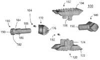
- FIG. 3is an exploded perspective view of the spinal fusion cage of FIG. 1.
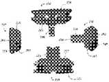
- FIG. 4is an exploded perspective view of the spine fusion cage of FIG. 1 as viewed from above, excluding the adjusting member.
- FIG. 5is an exploded perspective view as viewed from the lower side of the spinal fusion cage of FIG. 1, excluding the adjusting member.
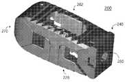
- FIG. 6is a perspective view of the lowest height state of the second embodiment of the spinal fusion cage according to the present invention.
- FIG. 7is a perspective view of the vertebral fusion cage of FIG. 6 at its highest height.
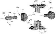
- FIG. 8is an exploded perspective view of the spinal fusion cage of FIG. 6.
- FIG. 9is an exploded perspective view as viewed from the upper side of the spinal fusion cage of FIG. 6, excluding the adjusting member.
- FIG. 10is an exploded perspective view as viewed from the lower side of the spinal fusion cage of FIG. 6, excluding the adjusting member.
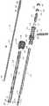
- FIG. 11is a perspective view of an embodiment of a cage holder according to the present invention.
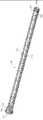
- FIG. 12is a cross-sectional perspective view of the cage holder of FIG. 11.
- FIG. 13is a partially enlarged cross-sectional view of the cage holder of FIG. 11.
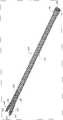
- FIG. 14is an exploded perspective view of the cage holder of FIG. 11.
- FIG. 15is a cross-sectional perspective view of the cage holder of FIG. 11 in an exploded state.
- 16is a perspective view of the main body.
- 17is a perspective view of a holding body.
- FIG. 18is a partially enlarged plan view of the holding body of FIG. 16.
- FIG. 19is a plan cross-sectional view of the cage holder of FIG. 11 in an exploded state on the end effector side.
- knob 20is a perspective view of the knob.
- 21is a perspective view of a fixing part.
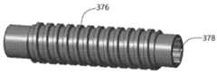
- 22is a perspective view of an exercise conversion unit.
- FIG. 23is a perspective view of a movement display unit.
- 24is a perspective view of a cover part.
- Example 25is a perspective view of the spinal fusion cage of Example 1 in a state close to the cage holder.
- 26is a perspective view of the spine fusion cage of Example 1 in the highest height state by being attached to the cage holder.
- FIG. 1 to 5show the spine fusion cage 100 according to the first embodiment
- Figures 6 to 10show the spine fusion cage 200 according to the second embodiment.
- the same components of the first and second embodimentswill be described together, and differences between the first and second embodiments will be described, respectively.
- the spinal fusion cages 100 and 200 according to the first embodimentwill be described with reference to FIGS. 1 to 5.
- the spinal fusion cage (100, 200)is between the first end plate (102, 202) and the second end plate (120, 220) and the upper first end plate (102, 202) and the second end plate (120, 220) which are arranged to face each other.
- Itincludes adjusting members 180 and 280 which penetrate through and connect to the end moving blocks 140 and 240.
- the first end plates 102 and 202 and the second end plates 120 and 220have first plate portions 104 and 204 and second plate portions 122 and 222 contacting the vertebrae.
- the first plate portions 104 and 204 and the second plate portions 122 and 222may have tooth protrusions to prevent separation from the vertebral body.
- first windows 118 and 218 and second windows 138 and 238 for inserting bone graftsare formed in the centers of the first plate portions 104 and 204 and the second plate portions 122 and 222, respectively. .
- first plate rails 111 and 211, second plate rails 112 and 212, third plate rails 113 and 213, and fourth plate rails 114 and 214are formed on both sides of the first plate portion 104 and 204 in the longitudinal direction. .
- the first plate rails 111 and 211 and the second plate rails 112 and 212are positioned to face each other in a distal direction, and first plate grooves 110 and 210 are formed therebetween.
- the third plate rails 113 and 213 and the fourth plate rails 114 and 214are positioned to face each other in a proximal direction, and second plate grooves 116 and 216 are formed therebetween.
- the first plate rail (111, 211), the second plate rail (112, 212), the third plate rail (113, 213), and the fourth plate rail (114,214)are all in the thickness direction from the surface of the first plate portion (104,204) It is formed to be inclined toward the center of the first plate portions 104 and 204 as it goes toward.
- fifth plate rails 131 and 231, sixth plate rails 132 and 232, seventh plate rails 133 and 233, and eighth plate rails 134 and 234are formed on both sides of the second plate portion 122 and 222 in the longitudinal direction.
- the fifth plate rails 131 and 231 and the sixth plate rails 132 and 232are positioned to face each other in a distal direction, and third plate grooves 130 and 230 are formed therebetween.
- the seventh plate rails 133 and 233 and the eighth plate rails 134 and 234are positioned to face each other in a proximal direction, and fourth plate grooves 136 and 236 are formed therebetween.
- the fifth plate rail (131,231), the sixth plate rail (132,232), the seventh plate rail (133,233), and the eighth plate rail (134,234)are all in the thickness direction from the surface of the second plate portion (122,222) As it goes toward, the second plate portions 122 and 222 are formed to be inclined in a direction approaching the center of the second plate portions 122 and 222.
- the distal movable blocks 140 and 240are formed in a streamlined shape by protruding insertion portions 142 and 242 to facilitate insertion between the vertebrae in the proximal direction.
- the terminal moving blocks 140 and 240have connection portions 144 and 244 elongated in the terminal direction, and connection screw portions 150 and 250 having a thread are formed inside the connection portions 144 and 244.
- the end movable blocks 140 and 240have first block protrusions 146 and 246 so as to correspond to the first plate grooves 110 and 210 of the first end plates 102 and 202, and the third of the second end plates 120 and 220 It has third block protrusions 148 and 248 so as to correspond to the plate grooves 130 and 230.
- first block rails 151 and 251 and second block rails 152 and 252 corresponding to the first plate rails 111 and 211 and the second plate rails 112 and 212are formed.
- Fifth block rails 151 and 251 and sixth block rails 162 and 262 corresponding to fifth plate rails 131 and 231 and sixth plate rails 132 and 232are formed around the third block protrusions 148 and 248.
- the proximal movable blocks 170 and 270have through holes 178 and 278 for supporting the adjustment members 180 and 280 so as to be rotatable therein.
- the proximal moving blocks 170 and 270have third block protrusions 172 and 272 so as to correspond to the second plate grooves 116 and 216 of the first end plates 102 and 202, and the fourth It has fourth block protrusions 174 and 274 so as to correspond to the plate grooves 136 and 236.
- third block protrusions 172 and 272third block rails 153 and 253 and fourth block rails 154 and 254 corresponding to the third plate rails 113 and 213 and the fourth plate rails 114 and 214 are formed.
- Seventh block rails 163 and 263 and eighth block rails 164 and 264 corresponding to the seventh plate rails 133 and 233 and the eighth plate rails 134 and 234are formed around the fourth block protrusions 174 and 274.
- fixing pin holes 176 and 276are formed at side portions of the proximal movable blocks 170 and 270 to accommodate fixing pins 192,194, 292, and 294.
- fastening portions 166 and 266are formed on the sides of the proximal movable blocks 170 and 270 so as to grip the spinal fusion cages 100 and 200 by means of an instrument.
- the distal movable blocks 140 and 240 and the proximal movable blocks 170 and 270have an approximately wedge shape and are raised or lowered by adding the first end plates 102 and 202 and the second end plates 120 and 220.
- the adjusting members 180 and 280may have an approximately bolt shape. That is, the adjustment members 180 and 280 have heads 182 and 282 and adjustment screw portions 188 and 288.
- the heads 182 and 282are located in openings formed in the proximal direction of the through holes 178 and 278, and the adjustment screw portions 188 and 288 pass through the through holes 178 and 278, and the connection screw portions 150 and 250 and the screw of the connection portions 144 and 244 Are combined.
- the heads 182 and 282are provided with tool seats 190 and 290 that can be connected to an instrument not shown.
- support portions 186 and 286are positioned between the heads 182 and 282 and the through holes 178 and 278 so as to be rotated while contacting the inner wall surfaces of the through holes 178 and 278.
- pin seat portions 184 and 284are formed around the support portions 186 and 286, and the ends of the fixing pins 192,194,292,294 inserted through the pinholes 176 and 276 of the proximal movable blocks 170 and 270 are located. As a result, the adjustment members 180 and 280 can be rotated in place.
- a pair of pillars 108 and 208are formed on both sides of the first plate portions 104 and 204 in a thickness direction, that is, in a direction toward the second end plates 120 and 220. Further, the receiving portions 106 and 206 are formed around the pillars 108 and 208 to accommodate the extension walls 124 and 224 mentioned below. Further, extension walls 124 and 224 are formed on both sides of the second end plates 120 and 220 in a thickness direction, that is, in a direction toward the first end plates 102 and 202, and the pillars ( Grooves 126 and 226 that can be guided in a state receiving 108 and 208 are formed.
- the first end plates 102 and 202 and the second end plates 120 and 220are in a direction that is close to or separated from each other. The movement of is constrained.
- the extension walls 124 and 224include first walls 1241 and 2241 and second walls 1242 respectively positioned at the front and rear ends of the pillar 108 along the longitudinal direction of the second end plate 120. 2242), and third walls 1243 and 2243 that connect the first walls 1241 and 2241 and the second walls 1242 and 2242 to form a groove 126 into which the pillar 108 is inserted. Including. That is, the extension walls 124 and 224 are formed to surround the pillars 108 and 208 while having an approximately U-shape when viewed from the top.
- the thicknesses of the first walls 1241,2241 and the second walls 1242,2242are smaller than the widthwise lengths of the second plate portions 122,222 minus the widthwise lengths of the second windows 138,238 Is formed. This is because the first walls 1241 and 2241 and the second walls 1242 and 2242 are inserted into the receiving portions 106 and 206 of the first end plate 102.
- the thickness of the pillars 108 and 208 in the width directionis greater than 1/4 times of the widthwise length of the first plate portions 104 and 204 excluding the widthwise length of the first windows 118 and 218 and is greater than 1/2 times. It is possible to form small. This is because the pillars 108 and 208 are thickened by the depth of the grooves 126 and 226 into which the pillars 108 and 208 are inserted.
- guide grooves 128 and 228 for guiding insertion of the pillars 108 and 208 into the grooves 126 and 226may be formed in the first walls 1241 and 2241 and the second walls 1242 and 2242. This is because the thicknesses of the pillars 108 and 208 are larger than the thicknesses of the first walls 1241 and 2241 and the second walls 1242 and 2242.
- the vertebral fusion cage 100 of Example 1 and the vertebral fusion cage 200 of Example 2are different in relative positions of the first end plates 102 and 202 and the second end plates 120 and 220 at the lowest height. .
- the vertebral fusion cage 200 of the second embodimentwhen the vertebral fusion cage 200 of the second embodiment is in its lowest state, the first bottom surface 205 of the first end plate 202 and the first wall of the second end plate 220 ( 2241) and a stopper 229 formed on the second wall 2242 are formed to come into contact with each other.
- the stopper 229protrudes from the first wall 2241 and the second wall 2242 and abuts around the receiving portion 206 of the bottom surface 205 of the first end plate 202. .
- the first to eighth block rails and the first The inclination of the 1 to 8 plate railsshould be maintained the same as the spinal fusion cage 100 of Example 1. Therefore, the bottom surface 205 of the first end plate 202 and the bottom surface 223 of the second end plate 220 need to be spaced apart from each other, and in the second embodiment, the stopper 229 is added. Include as.
- the spinal fusion cages 100 and 200are configured as described above, and the proximal movable blocks 170 and 270 and the distal movable blocks 140 and 240 are formed by inserting a device such as a driver into the tool grooves 190 and 290 and rotating in one direction. As a result, the first end plates 102 and 202 and the second end plates 120 and 220 are separated from each other. Similarly, the distance between the proximal movable blocks 170 and 270 and the distal movable blocks 140 and 240 is separated by inserting the device and rotating in the other direction, and as a result, the first end plate 102 and 202 and the second end Movement to increase the distance between the plates 120 and 220 is possible.
- one cagecan respond to a height within a certain range, thereby reducing the burden of inventory and production, and reducing the number of repetitive operations during surgery, reducing the labor of the doctor, as well as operating time. Since it also decreases, the amount of bleeding is reduced, and the recovery time of the patient is also greatly shortened. Therefore, it is expected to be widely used in the relevant field.
- the cage holder 300according to an embodiment of the present invention will be described with reference to FIGS. 11 to 24.
- the cage holder 300is largely inserted into the main body 302 and the main body 302 so as to be relatively movable with respect to the main body 302, and a pair of ends at one end of the main body 302
- a holding body 304 to which the effectors 344 and 346 are exposedA fixing part 308 integral with the holding body 304;
- a knob 306fixed to the other end of the main body 302 and coupled to the fixing part 308 so as to be movable in the longitudinal direction of the main body 302.
- the end effectors 344 and 346are formed at the ends of the legs 330 and 332 branching from one end of the holding body 304, and the legs 330 and 332 are forcibly applied to one end of the main body 302 and the legs 330 and 332.
- a guide portionmay be formed to guide it.
- the driver 310can be inserted through the inside of the fixing part 308 and the holding body 304, and the rotation amount of the driver can be converted into a length change amount and displayed on the fixing part 308.
- a display devicemay be additionally included.
- Each of the guide unit and the display devicemay be included in the cage holder 300 or both.
- the main body 302has a main body pipe 312 having a main body hole 326 therein, and there is one washing hole 314 along its longitudinal direction to facilitate cleaning. It can be placed longer.
- An opening 320 communicating with the main body hole 326is formed at one side of the main body tube 312, and the end effectors 344 and 346 protrude outward through the opening 320.
- the opening 320has a substantially straight end, but may be concave or convex in accordance with the shape of the proximal portion of the cage.
- An extension part 316is disposed on one side of the main body tube 312.
- the expansion part 316is expanded in the width direction (matching the width direction of the cage) compared to the main body tube 312 so that the end effectors 344 and 346 formed at the ends of the legs 330 and 332 are opened in the width direction. .
- the guide portionmay be formed only if it includes a guide rod disposed on the extension part 316 side and elongated on the legs 330 and 332, and a fixed guide disposed on the main body 302 and inserted into the guide rod. .
- the guide rodis formed as a guide slot (340, 342) long in a longitudinal direction penetrating through the legs (330, 332), and the fixing guide passes through the guide slots (340, 342) to the main body (302). It may be composed of fixed guide pins (406,408).
- a guide pin hole 318 through which the guide pins 406 and 408 can be installedis formed at one end of the main body tube 312.
- a fitting groove 324is formed at the other end of the main body tube 312 and serves to couple with the knob 306. In addition, it serves to prevent separation of the knob 306 by moving the locking projection 322 away from the other end of the main body tube 312 than the fitting groove 324.
- the holding body 304has a holding body tube 328 inserted into the main body 302, as shown in FIGS. 17 and 18, and two legs having one end branching from the branch part 334 ( 330,332). Bend grooves 336 and 338 are formed in the legs 330 and 332 outward, and serve to increase the amount of bending.
- End effectors 344 and 346are disposed at ends of the legs 330 and 332 to hold the cage.
- guide slots 340 and 342are formed on the legs 330 and 332 as described above.
- a binding portion 350is formed at the other end of the holding body 304 and is fixed to the fixing portion.
- the bonding method of the bonding unit 350may be performed through known techniques such as screwing by screw wire, welding, pin fixing, and epoxy bonding.
- the knob 306serves to apply a rotational force to move the holding body 304 with respect to the main body 302.
- a knob body 352 having an unevenness formed so as to be easily gripped by hand, a binding groove 354 connected to the fitting groove 324 of the main body 302, and a fixing portion 308 to be described beloware fixed.
- a knob screw 356 that meshes with the top screw 362is formed.
- the inside of the knob 306is formed with a knob hole 358 to have a shape of a tube as a whole.
- the fixing part 308has a fixing part screw 362 formed at one end of the fixing part body 360.
- a marking portion 364is formed at the other end.
- the marking part 364is a tube body communicating with the fixing part hole 368 of the fixing part 308, and a plurality of marking part slots 366 are formed along the length direction.
- a fixing part guide groove 370is formed on the inner wall surface of the fixing part hole 368 in the marking part 364 so that the moving display part 380 can be inserted.
- the fixing part 308has a handle fastening part 372 formed therein, the handle 392 may be inserted and fixed.
- a connecting chuck 394 capable of attaching an additional handlemay be formed on the handle 392.
- a scale capable of expressing the lengthis displayed on the marking unit 364, and a current height state of the cage may be displayed by a marker displayed on the movement display unit 380.
- a motion conversion part 376is inserted into the fixing part hole 368 of the marking part 364 and is supported so as to be rotatable by a rotation support part 374.
- a threadis formed on the outside of the movement conversion unit 376, and the thread is combined with the movement display screw unit 386 of the movement display unit 380. If the thread is the same as the pitch of the thread of the adjusting member of the cage, the amount of movement of the moving display unit 380 is small and it is difficult to visually grasp it, so that it is larger than the pitch of the thread of the adjusting member so that the lead of the adjusting member can be enlarged. , Try to have multiple lines.
- the movement display portion 380is formed with a movement display protrusion 384 around the movement display body 382 so as to be guided by protruding from the marking portion slot 366.
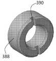
- the movement display unit 380is inserted into the marking unit 364 of the fixing unit 308 and fastens the cover unit 388 to prevent the movement display unit 380 from being separated.
- the cover part 388is fixed to the end of the marking part 364 using known techniques such as screwing, welding, and epoxy.
- the cover part 388may be formed with a cover part tool groove 390 for fastening a tool or the like.
- the driver 310is inserted through the fixing part 308 and the holding body hole 348.
- a drive tip 398is formed at one end of the driver 310 and may be coupled with an adjustment member of the cage.
- a driver attachment part 400 corresponding to a driver seat 378 formed in an opening of the exercise conversion part hole 410 of the exercise conversion part 376may be formed at the other end of the driver 310.
- a driver chuck 404 capable of being connected to a handlemay be formed by continuously placing a connection part 402 on the driver fixing part 400.
- the coupling ring 412is inserted into the fitting groove 324 of the main body 302 and the coupling groove 354 of the knob 306 to be fixed. Accordingly, the main body 302 and the knob 306 are fixed to each other, and the knob 306 can rotate with respect to the main body 302.
- the binding portion 350 of the holding body tube 328is inserted and fixed into the fixing portion 308. Accordingly, the fixing part 308 and the holding body tube 328 become one body. Further, the fixing part screw 362 of the fixing part 308 and the knob screw 356 of the knob 306 are screwed together.
- the knob 306when the knob 306 is rotated, the knob screw 356 rotates with respect to the fixing part screw 362, and the main body 302 can be brought close to or spaced apart from the fixing part 308. .
- the holding body 304 integral with the fixing part 308moves forward and backward, and the legs 330 and 332 formed at one end of the holding body 304 move forward and backward.
- the movement of the end effectors 344 and 346 by the forward and backward movement of the legs 330 and 332is as described above.
- the display deviceincludes a marking portion 364 connected to the fixing portion 308 and a driver seat 378 inserted into the marking portion 364 and on which the driver 310 is seated.
- the current height of the cagemay be determined by reading a position where the marking formed on the marking part 364 and the marking of the moving display protruding part 384 coincide.
- FIG. 25the state in which the spinal fusion cage 100 and the cage holder 300 are bound is shown in FIG. 25.
- the cage holder 300is close to the cage holder 300 with the lowest height, so that the end effectors 344 and 346 are located around the fastening portion 166 formed on the side of the spinal fusion cage 100. do.
- the holding body 304is retracted, and the end effectors 344 and 346 are inserted into the fastening part 166 to fix the spinal fusion cage 100.
- the shape of the opening 320corresponds to the shape of the proximal movable block 170, it is possible to closely contact each other, thereby preventing the spinal fusion cage 100 from shaking.
- the driver 310by inserting the driver 310, the drive tip 398 of the driver 310 is fastened to the tool groove 190 of the adjusting member 180. And, when the driver 310 is rotated, the first end plate as shown in FIG. 25 while the proximal movable block 170 and the distal movable block 140 are brought close to each other while the adjusting member 180 rotates. (102) and the second end plate 120 is separated from each other.
- the cage holder of the present inventionit is possible to insert the vertebral fusion cage between adjacent vertebral bodies, and since it is possible to stably separate and separate from the cage, accidents that may occur during surgery can be prevented.
- first plate portion 105,205first bottom surface
- first window 120,220second end plate
- 140,240end moving block 142,242: insertion part
- connection part 146,246first block protrusion
- fastening part 170,270proximal moving block
- cage holder 302main body
- extension part 318guide pinhole
- fitting groove 326main body hole
- branch part 336,338bending groove
- knob body 354coupling groove
- knob screw 358knob hole
- marking part 366marking part slot
- fixing part hole 370fixing part guide groove
- movement display unit 382movement display unit body
- driver attachment portion 402connection portion
Landscapes
- Health & Medical Sciences (AREA)
- Engineering & Computer Science (AREA)
- Biomedical Technology (AREA)
- Orthopedic Medicine & Surgery (AREA)
- Neurology (AREA)
- Transplantation (AREA)
- Oral & Maxillofacial Surgery (AREA)
- Cardiology (AREA)
- Heart & Thoracic Surgery (AREA)
- Vascular Medicine (AREA)
- Life Sciences & Earth Sciences (AREA)
- Animal Behavior & Ethology (AREA)
- General Health & Medical Sciences (AREA)
- Public Health (AREA)
- Veterinary Medicine (AREA)
- Physical Education & Sports Medicine (AREA)
- Surgical Instruments (AREA)
- Prostheses (AREA)
Abstract
Description
Translated fromKorean본 발명은 척추 유합 케이지의 케이지 홀더에 관한 것으로, 더욱 상세하게는 척추 유합 케이지와 장착되서, 척추 유합 케이지를 안정적으로 추체 사이에 삽입시킬 수 있는 케이지 홀더에 관한 것이다.The present invention relates to a cage holder of a vertebral fusion cage, and more particularly, to a cage holder mounted with a vertebral fusion cage and capable of stably inserting the vertebral fusion cage between vertebrae.
추체는 몸통을 이루는 32~35개의 척추골(vertebra)과 척추골 사이의 추간판 (intervertebral disk) 즉, 디스크로 이루어지며, 상단의 두개골과 하단의 골반을 연결하는 우리 몸의 중추를 이루는 부분이다.The vertebrae are made up of 32 to 35 vertebrae that make up the body and intervertebral disks, that is, disks between the vertebrae, and are the central part of our body that connects the skull at the top and the pelvis at the bottom.
척추골은 위로부터 7개의 경추(cervical), 12개의 흉추(thoracic), 5개의 요추(lumber), 5개의 천추(sacrum), 3~5개의 미추(coccyx)로 이루어지는데, 성인에서는 5개의 천추가 유합하여 1개의 천골이 되고, 3~5개의 미추가 유합하여 1개의 미골이 된다.The vertebrae are composed of 7 cervical, 12 thoracic, 5 lumber, 5 sacrum, and 3~5 coccyx from the top.In adults, 5 sacrum By fusion, it becomes 1 sacrum, and 3~5 coccyx are fused to become 1 coccyx.
오랫동안 심각한 척추질환의 치료를 위한 치료 방법의 하나로 척추의 유합술이 있다. 이러한 척추 유합술은 추간판(디스크; intervertebral disc)을 제거하고 이를 대체하는 케이지(Cage)를 삽입하여 인접하는 추체를 서로 유합시키는 수술법이다.One of the treatment methods for the treatment of serious spinal diseases for a long time is spinal fusion. This spinal fusion is a surgical method in which adjacent vertebrae are fused together by removing an intervertebral disc and inserting a replacement cage.
이러한 척추 유합술은 요추에 시술될 경우, 케이지의 삽입방향에 따라, 후방추체 유합술(Posterial Lumbar Interbody Fusion, PLIF), 횡추간공 추체 유합술(Transformational Lumbar Interbody Fusion, TLIF), 측방 추체 유합술(Lateral lateral Lumbar Interbody Fusion, LLIF), 사측방 추체유합술 (Oblique Lumbar Interbody Fusion, OLIF), 전방추체 유합술(Anterior Lumbar Interbody Fusion, ALIF) 등으로 구분될 수 있다.If such spinal fusion is performed on the lumbar spine, depending on the insertion direction of the cage, the posterior lumbar interbody fusion (PLIF), the Transformational Lumbar Interbody Fusion (TLIF), the Lateral lateral Lumbar Interbody Fusion, LLIF), oblique lumbar interbody fusion (OLIF), and anterior lumbar interbody fusion (ALIF).
후방추체 유합술(PLIF)은 척추의 중심선을 따라 절개를 하고, 척추체가 모두 노출되도록 개방하고 척추뼈의 후방측 일부를 제거한 후 디스크를 제거하고 PLIF 케이지를 삽입하는 방법이다.In the posterior vertebral fusion (PLIF), an incision is made along the center line of the spine, open to expose all of the vertebrae, and after removing a part of the posterior side of the vertebrae, the disc is removed and the PLIF cage is inserted.
후방추체 유합술(PLIF)은 척추 유합술 중 가장 오래전부터 시행해온 것으로써, 두마디나 세마디 유합술을 할 때 꼭 필요한 방법이다. 하지만, 수술과정으로 인해 신경과 인대와 근육에 유착이 될 가능성이 많고, 절개영역이 커서 치유시간이 길며, 사람에 따라서는 후유증이 큰 단점이 있다.Posterior vertebral fusion (PLIF) has been performed since the longest among spinal fusion, and is a necessary method when performing two- or three-node fusion. However, there is a high possibility of adhesion to the nerves, ligaments and muscles due to the surgical procedure, the healing time is long due to the large incision area, and the sequelae is large depending on the person.
PLIF 케이지는 한쌍의 작은 케이지가 좌우 양측에 배치되며, 모든 척추 유합술에 사용되는 케이지 중에서 가장 작다.The PLIF cage has a pair of small cages placed on both left and right sides, and is the smallest of all cages used for spinal fusion.
횡추간공 추체 유합술(TLIF)은, 척추 근육 양옆을 따라 작게 절개를 하고 최소한으로 척추체를 노출시키고 난 이후 척추 관절 부위를 신경공이 나오는 방향으로 제거하면서 TLIF 케이지를 디스크를 삽입하는 수술 방법이다. 이 수술기법은 출혈도 적고, 수술 시간도 단축시키는 장점이 있기 때문에 한 마디 수술인 경우에 적합하지만 여러 부위 수술이 필요한 경우에는 PLIF 수술을 해야 한다. TLIF 케이지는 대부분 원호 형상으로 되어 있어서, 추체에 넣고 회전시켜 TLIF 케이지의 볼록한 부분이 배쪽을 향하도록 한다. TLIF 케이지는 PLIF 케이지보다는 크지만 지지면적이 이후에 언급할 LLIF 케이지 또는 ALIF 케이지 보다는 작다.Transverse intervertebral cavity fusion (TLIF) is a surgical method in which a TLIF cage is inserted into a disc while removing the vertebral joint in the direction of the nerve hole after making small incisions along both sides of the vertebral muscle and exposing the vertebral body to a minimum. Since this surgical technique has the advantage of less bleeding and shortening the operation time, it is suitable for single-word surgery, but if multiple site surgery is required, PLIF surgery should be performed. Most of the TLIF cages are arc-shaped, so they are placed in the vertebrae and rotated so that the convex part of the TLIF cage faces the abdomen. The TLIF cage is larger than the PLIF cage, but the supporting area is smaller than the LLIF cage or ALIF cage, which will be mentioned later.
전방추체 유합술(ALIF)은 수술회복도 빠르고 유착도 걱정할 필요가 없는 등의 여러가지 장점이 있지만, 전방(배쪽)을 절개하여 내장을 제치며 척추쪽으로 접근해서 시행하므로 고도의 숙련된 기술이 필요하다는 단점이 있다. ALIF 케이지는 모든 척추 유합술 케이지 중에서 가장 큰 지지면적을 가지는 장점이 있다.Anterior vertebral fusion (ALIF) has several advantages, such as quick surgical recovery and no need to worry about adhesion, but it has the disadvantage of requiring a highly skilled technique since it is performed by making an incision in the anterior (abdominal) side to overcome the intestines and approaching the spine. have. The ALIF cage has the advantage of having the largest support area among all spinal fusion cages.
ALIF, PLIF, TLIF의 단점을 극복하기 위해 개발된 것이 측방 추체 유합술(LLIF)이다. 측방 추체 유합술은 옆구리 절개를 통해 수술을 진행하므로 기존 등을 절개하는 수술들에 비해 척추와 척추 사이 협착된 부위의 간격을 더욱 넓게 넓힐 수 있는 것을 물론이고 주위 조직의 손상이 거의 없는 장점이 있다. 다만, 수술하는 경로 주위에 대요근(Psoas muscle) 및 복막(peritoneum)이 있어서, 수술시 실수가 있으면 허벅지 근육 마비가 오는 등의 문제가 있다. LLIF 케이지는 ALIF 케이지보다는 작지만, PLIF 케이지나 TLIF 케이지보다는 작다.Lateral vertebral fusion (LLIF) was developed to overcome the shortcomings of ALIF, PLIF, and TLIF. Since the lateral vertebral fusion surgery is performed through a flank incision, it has the advantage of not only being able to widen the gap between the spine and the constricted area between the spine, but also almost no damage to the surrounding tissues compared to conventional back incisions. However, there are Psoas muscle and peritoneum around the surgical path, so if there is a mistake during the operation, there is a problem such as paralysis of the thigh muscle. The LLIF cage is smaller than the ALIF cage, but smaller than the PLIF cage or TLIF cage.
이러한 측방 추체 유합술에 비해 보다 안전하고 효과적인 수술법이 사측방 추체 유합술(OLIF(Oblique Lumbar Interbody Fusion) 또는 ATP(Anterior To Psoas) fusion)이다. 사측방 추체 유합술은 옆구리에서 기술어진 방향으로 수술 경로가 이루어지며, 대요근(Psoas muscle) 및 복막(peritoneum)에 의해 수술이 DLIF으로는 수술이 어려운 4번요추(L4)와 5번요추(L5) 사이에도 가능한 장점이 있다. 또한, 측방 추체 유합술에서 문제가 되는 신경에 손상을 줄 가능성이 현저하게 적다.Compared to this lateral vertebral fusion, a safer and more effective surgical method is OLIF (Oblique Lumbar Interbody Fusion) or ATP (Anterior To Psoas) fusion. In the quadralateral vertebral fusion, the surgical path is made in the direction described from the side, and the Psoas muscle and peritoneum are difficult to operate with DLIF, and the 4th lumbar spine (L4) and the 5th lumbar spine (L5) are difficult to operate with DLIF. ), there are also possible advantages. In addition, the possibility of damaging the nerves in question in the lateral vertebral fusion is significantly less.
기존의 척추 유합 케이지는 티타늄과 같은 금속 재질 또는 PEEK와 같은 고분자 물질을 이용하여 단면적 또는 높이의 변화가 없는 단체(one body)로 제작되었다. 그렇기 때문에 환자의 체격, 신장, 인종, 성별 등을 고려하여 상당히 많은 수의 제품구성을 가지고 있다. 즉, 제조자 입장에서는 가로, 세로, 높이의 3가지 변수를 조합하여 적게는 수십에서 많게는 수백가지의 제품군을 제작해야 하는 부담이 있었다.Existing spinal fusion cages are made of a single body with no change in cross-sectional area or height by using a metal material such as titanium or a polymer material such as PEEK. Therefore, it has a fairly large number of products in consideration of the patient's physique, height, race, and gender. In other words, from a manufacturer's point of view, there was a burden of manufacturing product lines of as few as tens to as many as hundreds by combining three variables of width, length and height.
또한, 환자의 척추 사이의 간격이 일정한 간격으로 커지는 것이 아니지만, 단체로 제작하는 경우에는 이미 존재하는 제품군에서 적절한 높이를 골라서 수술해야 하므로, 각각의 환자에 제대로 대응할 수 없는 문제가 있다.In addition, the spacing between the patient's spines does not increase at regular intervals, but if it is manufactured as a group, it is necessary to select an appropriate height from an existing product line for surgery, so there is a problem that it cannot respond properly to each patient.
이를 해결하기 위해 다양한 시도가 있었으며, 높이를 조절할 수 있는 척추 유합 케이지가 개발되었다.Various attempts have been made to solve this problem, and a spinal fusion cage capable of adjusting the height has been developed.
US6176882에는 이러한 높이를 조절할 수 있는 케이지가 개시되어 있다. US6176882의 케이지는 위 아래가 개방된 사각상자 형태의 벽과, 상기 벽 내부에서 상하로 움직이는 결합부재(engagement member)와, 상기 결합부재를 밀어부치는 한쌍의 쐐기부재(wedge member)와, 상기 한쌍의 쐐기부재와 나사결합하여 한쌍으 쐐기부재의 간격을 조절하는 조절부재(adjusting element)를 포함하여 이루어진다. 따라서, US6176882는 상자형태의 벽에 의해 구속될 뿐, 결합부재와 쐐기부재가 서로 연결되지 않아서 결합부재가 흔들리는 문제가 있다.US6176882 discloses a cage capable of adjusting this height. The cage of US6176882 includes a wall in the form of a square box with an open top and bottom, an engagement member moving up and down in the wall, a pair of wedge members pushing the engagement member, and the pair of It comprises a wedge member and an adjusting element (adjusting element) for adjusting the spacing of the pair of wedge members by screwing. Therefore, US6176882 is only constrained by a box-shaped wall, there is a problem that the coupling member and the wedge member are not connected to each other, so that the coupling member is shaken.
US9034041에는 비교발명 4의 청구항 1의 발명은, 크게 바디 어셈블리(body assembly), 상부지지부재(upper support members, 718), 하부지지부재(lower support member,720)를 포함하고, 상기 바디 어셈블리는, 제1부분(712)과, 제2부분(714)을 가지며, 상기 제1부분(712)과 상기 제2부분(714)은 조절부재(control member)에 의해 길이방향 축선 상에서 이동한다. 상기 상부지지부재(718)와 상기 하부지지부재(720) 사이의 간격은 한쌍의 제1 상부 유지부재(retaining member)와, 한쌍의 제2상부 유지부재(retaining member)에 의해 한정된다. 따라서, US9034041는 상기 상부지지부재(718)와 상기 하부지지부재(720)의 상호 이동을 직접적으로 가이드하는 구성요소가 포함되지 않아서, 바디 어셈블리와, 상기 상부지지부재(718)와 상기 하부지지부재(720)가 서로에 대해 흔들리는 문제가 있다.In US9034041, the invention of claim 1 of Comparative Invention 4 largely includes a body assembly, an upper support member 718, and a lower support member 720, wherein the body assembly, A first portion 712 and a second portion 714 are provided, and the first portion 712 and the second portion 714 are moved on a longitudinal axis by a control member. The distance between the upper support member 718 and the lower support member 720 is defined by a pair of first upper retaining members and a pair of second upper retaining members. Therefore, US9034041 does not include a component that directly guides the mutual movement of the upper support member 718 and the lower support member 720, so that the body assembly, the upper support member 718 and the lower support member There is a problem with 720 shaking against each other.
US2017-02580605A의 도 26 내지 도 29에는 높이 조절이 가능한 케이지용 홀더(400)가 개시되어 있다. US2017-02580605는 복수의 암(402)이 슬리브(410) 내부로 삽입되거나 돌출되면서 상기 암(402) 끝단의 돌기(404)가 케이지(300)의 홈(320)에 장착되어 상기 케이지(300)를 고정하는 방식이다. 그러나, 이러한 방식은 상기 암(402)의 탄성에 의해 확장되므로, 반복해서 사용되거나 수술부위에서 주위근육의 방해 등으로 인해, 홀더(400)가 임플란트(302)와 결합된 상태로 분리되지 않을 가능성이 높다는 문제가 있다. 또한, 기존의 케이지용 홀더에서는 케이지의 높이 변화를 정확하게 알 수 없고, 시술자의 경험으로 판단하고 있다.In FIGS. 26 to 29 of US2017-02580605A, a
{선행기술문헌} {Prior technical literature}
[특허문헌] [Patent Literature]
US6176882US6176882
US9034041US9034041
US2017-0258605AUS2017-0258605A
상술한 문제점을 해결하기 위해 안출된 본 발명의 목적은, 척추 유합 케이지와 장착되서 척추 유합 케이지를 최저높이로 추체 사이에 삽입시키고, 수술 후 확실하게 척추 유합 케이지로부터 분리될 수 있는 케이지 홀더에 관한 것이다.An object of the present invention was conceived to solve the above-described problems, to a cage holder that is mounted with a spinal fusion cage and inserts the vertebral fusion cage between the vertebrae at the lowest height, and can be reliably separated from the vertebral fusion cage after surgery. will be.
본 발명의 또 다른 목적은, 높이를 조절할 수 있는 척추 유합케이지에 장착되면, 척추 유합 케이지의 높이 변화량을 가시적으로 표시할 수 있는 케이지 홀더에 관한 것이다.Another object of the present invention relates to a cage holder capable of visually displaying the amount of change in height of the vertebral fusion cage when mounted on a vertebral fusion cage capable of adjusting the height.
상술한 목적을 달성하기 위한 본 발명은, 메인바디; 상기 메인바디 내부에 삽입되어 상기 메인바디에 상대적으로 이동가능하고, 상기 메인바디의 일단으로 한쌍의 엔드이펙터가 노출되는 홀딩바디; 상기 홀딩바디와 일체인 고정부; 및 상기 메인바디의 타단에 고정되고, 상기 고정부에 대해 상기 메인바디의 길이방향으로 이동이 가능하게 결합되는 노브를 포함하고, 상기 엔드이펙터는 상기 홀딩바디의 일단에서 분기되는 다리의 단부에 형성되며, 상기 메인바디의 일단과 상기 다리에는 상기 다리를 강제적으로 안내하는 가이드부가 형성되며, 상기 홀딩바디가 상기 메인바디의 길이방향에 대하여 일단 방향으로 전진하여 상기 엔드이펙터의 돌출량이 증가하면 상기 한쌍의 엔드이펙터 사이의 간격이 멀어지고, 상기 홀딩바디가 상기 메인바디의 길이방향에 대하여 일단 방향으로부터 후퇴하면 상기 엔드이펙터의 돌출량이 감소하면 상기 한쌍의 엔드이펙터 사이의 간격이 가까워지는 것을 특징으로 하는 케이지 홀더이다.The present invention for achieving the above object, the main body; A holding body inserted into the main body to be relatively movable to the main body, and to expose a pair of end effectors to one end of the main body; A fixing part integral with the holding body; And a knob fixed to the other end of the main body and movably coupled to the fixing part in a longitudinal direction of the main body, and the end effector is formed at an end of a leg branching from one end of the holding body. And, a guide portion for forcibly guiding the leg is formed at one end of the main body and the leg, and when the holding body advances in one direction with respect to the longitudinal direction of the main body and the protrusion of the end effector increases, the pair The distance between the end effectors of the end effector increases, and when the holding body is retracted from the longitudinal direction of the main body once from the direction, the protrusion of the end effector decreases, the distance between the pair of end effectors becomes close. It is a cage holder.
상기 가이드부는 상기 다리에 길게 형성되는 가이드로드와, 상기 메인바디에 배치되고 상기 가이드로드에 삽입되는 고정가이드를 포함하는 것을 특징으로 한다.The guide portion is characterized in that it comprises a guide rod that is elongated in the leg, and a fixed guide disposed on the main body and inserted into the guide rod.
또, 상기 가이드로드는 상기 다리를 관통하는 길이방향으로 긴 가이드슬롯으로 형성되고, 상기 고정가이드는 상기 가이드슬롯을 관통하여 상기 메인바디에 고정되는 가이드핀인 것을 특징으로 한다.In addition, the guide rod is formed as a long guide slot in a longitudinal direction penetrating the leg, and the fixing guide is a guide pin that passes through the guide slot and is fixed to the main body.
또, 상기 다리에는 벤딩홈이 형성돼서, 상기 다리 사이의 폭의 변형량을 확대시키는 것을 특징으로 한다.In addition, a bending groove is formed in the legs, so that the amount of deformation of the width between the legs is increased.
또, 상기 고정부 및 상기 홀딩바디의 내부를 통해 드라이버가 삽입이 가능하고, 상기 고정부에는 상기 드라이버의 회전량을 길이변화량으로 전환하여 표시할 수 있는 표시장치가 포함되는 것을 특징으로 한다.In addition, a driver may be inserted through the fixing part and the holding body, and the fixing part includes a display device that converts and displays the rotation amount of the driver into a length change amount.
또, 상기 표시장치는, 상기 고정부에 연결되는 마킹부; 상기 마킹부의 내부에 삽입되고, 내측에 상기 드라이버가 안착되는 드라이버자리를 가지는 운동전환부; 및상기 운동전환부와 나사결합되고 상기 마킹부에 형성된 마킹부슬롯을 통해 외부에 노출돼서, 상기 드라이버의 회전에 의해 상기 운동전환부의 회전에 따라 상기 마킹부슬롯을 따라 이동하는 이동표시부를 포함되는 것을 특징으로 한다.In addition, the display device may include a marking part connected to the fixing part; A movement conversion unit inserted into the marking unit and having a driver seat on which the driver is seated; And a movement display unit that is screwed with the motion conversion unit and exposed to the outside through a marking unit slot formed on the marking unit, and moves along the marking unit slot according to the rotation of the movement conversion unit by rotation of the driver. It is characterized by that.
또, 상기 마킹부슬롯은 2개 이상이 형성되는 것을 특징으로 한다.In addition, the marking portion slot is characterized in that two or more is formed.
또, 상기 운동전환부에 형성된 나사부의 피치는 상기 케이지의 높이를 조절하는 조절부재에 형성된 나사부의 피치보다 큰 것을 특징으로 한다.In addition, the pitch of the threaded portion formed in the motion conversion portion is characterized in that it is greater than the pitch of the screw portion formed in the adjusting member for adjusting the height of the cage.
또, 상기 운동전환부에 형성된 나사부는 복수의 줄수를 가지는 나사인 것을 특징으로 한다.In addition, the screw portion formed in the motion conversion portion is characterized in that the screw having a plurality of rows.
또, 상기 이동표시부는 상기 마킹부슬롯에 삽입되어, 상기 마킹부슬롯의 길이에 의해 이동의 제한을 받는 이동표시돌출부를 포함하는 것을 특징으로 한다.In addition, the movement display portion is inserted into the marking portion slot, characterized in that it comprises a movement display protruding portion that is restricted in movement by the length of the marking portion slot.
또 다른 발명은, 메인바디; 상기 메인바디 내부에 삽입되어 상기 메인바디에 상대적으로 이동가능하고, 상기 메인바디의 일단으로 한쌍의 엔드이펙터가 노출되는 홀딩바디; 상기 홀딩바디와 일체인 고정부; 및 상기 메인바디의 타단에 고정되고, 상기 고정부에 대해 상기 메인바디의 길이방향으로 이동이 가능하게 결합되는 노브를 포함하고, 상기 고정부 및 상기 홀딩바디의 내부를 통해 드라이버가 삽입이 가능하고, 상기 고정부에는 상기 드라이버의 회전량을 길이변화량으로 전환하여 표시할 수 있는 표시장치가 포함되는 것을 특징으로 한다.Another invention, the main body; A holding body inserted into the main body to be relatively movable to the main body, and to expose a pair of end effectors to one end of the main body; A fixing part integral with the holding body; And a knob fixed to the other end of the main body and movably coupled to the fixing part in a longitudinal direction of the main body, and a driver can be inserted through the inside of the fixing part and the holding body. And a display device capable of displaying by converting the rotation amount of the driver into a length change amount is included in the fixing part.
상기 표시장치는, 상기 고정부에 연결되는 마킹부; 상기 마킹부의 내부에 삽입되고, 내측에 상기 드라이버가 안착되는 드라이버자리를 가지는 운동전환부; 및 상기 운동전환부와 나사결합되고 상기 마킹부에 형성된 마킹부슬롯을 통해 외부에 노출돼서, 상기 드라이버의 회전에 의해 상기 운동전환부의 회전에 따라 상기 마킹부슬롯을 따라 이동하는 이동표시부를 포함되는 것을 특징으로 한다.The display device includes: a marking part connected to the fixing part; A movement conversion unit inserted into the marking unit and having a driver seat on which the driver is seated; And a movement display unit that is screwed with the movement conversion unit and exposed to the outside through a marking unit slot formed on the marking unit, and moves along the marking unit slot according to the rotation of the movement conversion unit by rotation of the driver. It is characterized by that.
또, 상기 마킹부슬롯은 2개 이상이 형성되는 것을 특징으로 한다.In addition, the marking portion slot is characterized in that two or more is formed.
또, 상기 운동전환부에 형성된 나사부의 피치는 상기 케이지의 높이를 조절하는 조절부재에 형성된 나사부의 피치보다 큰 것을 특징으로 한다.In addition, the pitch of the threaded portion formed in the motion conversion portion is characterized in that it is greater than the pitch of the screw portion formed in the adjusting member for adjusting the height of the cage.
또, 상기 운동전환부에 형성된 나사부는 복수의 줄수를 가지는 나사인 것을 특징으로 한다.In addition, the screw portion formed in the motion conversion portion is characterized in that the screw having a plurality of rows.
또, 상기 이동표시부는 상기 마킹부슬롯에 삽입되어, 상기 마킹부슬롯의 길이에 의해 이동의 제한을 받는 이동표시돌출부를 포함하는 것을 특징으로 한다.In addition, the movement display portion is inserted into the marking portion slot, characterized in that it comprises a movement display protruding portion that is restricted in movement by the length of the marking portion slot.
또, 상기 엔드이펙터는 상기 홀딩바디의 일단에서 분기되는 다리의 단부에 형성되며, 상기 메인바디의 일단과 상기 다리에는 상기 다리를 강제적으로 안내하는 가이드부가 형성되며, 상기 홀딩바디가 상기 메인바디의 길이방향에 대하여 일단 방향으로 전진하여 상기 엔드이펙터의 돌출량이 증가하면 상기 한쌍의 엔드이펙터 사이의 간격이 멀어지고, 상기 홀딩바디가 상기 메인바디의 길이방향에 대하여 일단 방향으로부터 후퇴하면 상기 엔드이펙터의 돌출량이 감소하면 상기 한쌍의 엔드이펙터 사이의 간격이 가까워지는 것을 특징으로 한다.In addition, the end effector is formed at an end of a leg branching from one end of the holding body, and a guide portion forcibly guiding the leg is formed at one end of the main body and the leg, and the holding body is When the protrusion amount of the end effector increases by advancing in one direction with respect to the longitudinal direction, the distance between the pair of end effectors increases, and when the holding body retreats from the direction once with respect to the longitudinal direction of the main body, the end effector When the amount of protrusion decreases, the distance between the pair of end effectors becomes close.
또, 상기 가이드부는 상기 다리에 길게 형성되는 가이드로드와, 상기 메인바디에 배치되고 상기 가이드로드에 삽입되는 고정가이드를 포함하는 것을 특징으로 한다.In addition, the guide portion is characterized in that it comprises a guide rod that is elongated in the leg, and a fixed guide disposed on the main body and inserted into the guide rod.
또, 상기 가이드로드는 상기 다리를 관통하는 길이방향으로 긴 가이드슬롯으로 형성되고, 상기 고정가이드는 상기 가이드슬롯을 관통하여 상기 메인바디에 고정되는 가이드핀인 것을 특징으로 한다.In addition, the guide rod is formed as a long guide slot in a longitudinal direction penetrating the leg, and the fixing guide is a guide pin that passes through the guide slot and is fixed to the main body.
또, 상기 다리에는 벤딩홈이 형성돼서, 상기 다리 사이의 폭의 변형량을 확대시키는 것을 특징으로 한다.In addition, a bending groove is formed in the legs, so that the amount of deformation of the width between the legs is increased.
또, 다른 발명은, 메인바디; 상기 메인바디 내부에 삽입되어 상기 메인바디에 상대적으로 이동가능하고, 상기 메인바디의 일단으로 한쌍의 엔드이펙터가 노출되는 홀딩바디; 상기 홀딩바디와 일체인 고정부; 및 상기 메인바디의 타단에 고정되고, 상기 고정부에 대해 상기 메인바디의 길이방향으로 이동이 가능하게 결합되는 노브를 포함하고, 상기 엔드이펙터는 상기 홀딩바디의 일단에서 분기되는 다리의 단부에 형성되며, 상기 메인바디의 일단과 상기 다리에는 상기 다리를 강제적으로 안내하는 가이드부가 형성되며, 상기 홀딩바디가 상기 메인바디의 길이방향에 대하여 일단 방향으로 전진하여 상기 엔드이펙터의 돌출량이 증가하면 상기 한쌍의 엔드이펙터 사이의 간격이 멀어지고, 상기 홀딩바디가 상기 메인바디의 길이방향에 대하여 일단 방향으로부터 후퇴하면 상기 엔드이펙터의 돌출량이 감소하면 상기 한쌍의 엔드이펙터 사이의 간격이 가까워지고, 상기 고정부 및 상기 홀딩바디의 내부를 통해 드라이버가 삽입이 가능하고, 상기 고정부에는 상기 드라이버의 회전량을 길이변화량으로 전환하여 표시할 수 있는 표시장치가 포함되는 것을 특징으로 하는 케이지 홀더이다.Another invention, the main body; A holding body inserted into the main body to be relatively movable to the main body, and to expose a pair of end effectors to one end of the main body; A fixing part integral with the holding body; And a knob fixed to the other end of the main body and movably coupled to the fixing part in a longitudinal direction of the main body, and the end effector is formed at an end of a leg branching from one end of the holding body. And, a guide portion for forcibly guiding the leg is formed at one end of the main body and the leg, and when the holding body advances in one direction with respect to the longitudinal direction of the main body and the protrusion of the end effector increases, the pair When the distance between the end effectors of the end effector increases and the holding body is retracted from the longitudinal direction of the main body once from the direction, the protrusion of the end effector decreases, the distance between the pair of end effectors becomes close, and the fixing part And a display device in which a driver can be inserted through the inside of the holding body, and the fixing part includes a display device that converts and displays a rotation amount of the driver into a length change amount.
본 발명을 통하여 높이 조절이 가능한 케이지 한개로 일정한 범위 내의 높이를 가지는 케이지를 대체할 수 있도록 작동시킬 수 있다. 따라서, 제조자 입장에서 생산해야 하는 제품군이 적어지고, 재고 또한 줄일 수 있다. 또한, 종래기술에서 일정한 간격으로 기설정된 높이를 가지는 케이지와 달리 환자의 추체 간격에 따라 선형적으로 높이가 조절되므로, 환자 상태에 따른 최적의 높이로 수술이 가능하다.Through the present invention, it is possible to operate to replace a cage having a height within a certain range with one cage capable of adjusting the height. Therefore, the number of product lines to be produced from the manufacturer's point of view can be reduced and inventory can be reduced. In addition, unlike a cage having a predetermined height at regular intervals in the prior art, since the height is linearly adjusted according to the vertebral spacing of the patient, the operation can be performed at an optimum height according to the patient's condition.
또, 시각적으로 케이지의 높이증대량을 체크할 수 있어서 의사에게 안정감을 줄 뿐 아니라, 더욱 정밀한 수술이 가능하다.In addition, since it is possible to visually check the amount of height increase of the cage, it not only gives the doctor a sense of stability, but also enables more precise surgery.
도 1은 본 발명에 따른 척추 유합 케이지의 실시예 1의 최저 높이 상태의 사시도이다.1 is a perspective view of the lowest height state of Example 1 of the spinal fusion cage according to the present invention.
도 2는 도 1의 척추 유합 케이지의 최고 높이 상태의 사시도이다.FIG. 2 is a perspective view of the spine fusion cage of FIG. 1 at the highest height.
도 3은 도 1의 척추 유합 케이지의 분해사시도이다.3 is an exploded perspective view of the spinal fusion cage of FIG. 1.
도 4는 도 1의 척추 유합 케이지를 상측에서 바라본 분해사시도이며, 조절부재를 제외한다.4 is an exploded perspective view of the spine fusion cage of FIG. 1 as viewed from above, excluding the adjusting member.
도 5는 도 1의 척추 유합 케이지를 하측에서 바라본 분해사시도이며, 조절부재를 제외한다.5 is an exploded perspective view as viewed from the lower side of the spinal fusion cage of FIG. 1, excluding the adjusting member.
도 6은 본 발명에 따른 척추 유합 케이지의 실시예 2의 최저 높이 상태의 사시도이다.6 is a perspective view of the lowest height state of the second embodiment of the spinal fusion cage according to the present invention.
도 7은 도 6의 척추 유합 케이지의 최고 높이 상태의 사시도이다.7 is a perspective view of the vertebral fusion cage of FIG. 6 at its highest height.
도 8은 도 6의 척추 유합 케이지의 분해사시도이다.8 is an exploded perspective view of the spinal fusion cage of FIG. 6.
도 9는 도 6의 척추 유합 케이지를 상측에서 바라본 분해사시도이며, 조절부재를 제외한다.9 is an exploded perspective view as viewed from the upper side of the spinal fusion cage of FIG. 6, excluding the adjusting member.
도 10은 도 6의 척추 유합 케이지를 하측에서 바라본 분해사시도이며, 조절부재를 제외한다.10 is an exploded perspective view as viewed from the lower side of the spinal fusion cage of FIG. 6, excluding the adjusting member.
도 11은 본 발명에 따른 케이지 홀더의 실시예의 사시도이다.11 is a perspective view of an embodiment of a cage holder according to the present invention.
도 12는 도 11의 케이지 홀더의 단면 사시도이다.12 is a cross-sectional perspective view of the cage holder of FIG. 11.
도 13은 도 11의 케이지 홀더의 부분확대 단면도이다.13 is a partially enlarged cross-sectional view of the cage holder of FIG. 11.
도 14는 도 11의 케이지 홀더의 분해 사시도이다.14 is an exploded perspective view of the cage holder of FIG. 11.
도 15는 도 11의 케이지 홀더의 분해상태의 단면 사시도이다.15 is a cross-sectional perspective view of the cage holder of FIG. 11 in an exploded state.
도 16은 메인 바디의 사시도이다.16 is a perspective view of the main body.
도 17은 홀딩 바디의 사시도이다.17 is a perspective view of a holding body.
도 18은 도 16의 홀딩 바디의 부분확대 평면도이다.18 is a partially enlarged plan view of the holding body of FIG. 16.
도 19는 도 11의 케이지 홀더의 엔드이펙터 측의 분해상태의 평단면도이다.19 is a plan cross-sectional view of the cage holder of FIG. 11 in an exploded state on the end effector side.
도 20은 노브의 사시도이다.20 is a perspective view of the knob.
도 21은 고정부의 사시도이다.21 is a perspective view of a fixing part.
도 22는 운동전환부의 사시도이다.22 is a perspective view of an exercise conversion unit.
도 23은 이동표시부의 사시도이다.23 is a perspective view of a movement display unit.
도 24는 커버부의 사시도이다.24 is a perspective view of a cover part.
도 25는 실시예 1의 척추 유합케이지를 케이지 홀더에 근접한 상태의 사시도이다.25 is a perspective view of the spinal fusion cage of Example 1 in a state close to the cage holder.
도 26은 실시예 1의 척추 유합케이지가 케이지 홀더에 결착돼서 최고 높이 상태의 사시도이다.26 is a perspective view of the spine fusion cage of Example 1 in the highest height state by being attached to the cage holder.
이하, 본 발명을 바람직한 실시예를 첨부한 도면을 참조하여 설명하기로 한다. 하기의 각 도면의 구성 요소들에 참조 부호를 부가함에 있어서, 동일한 구성 요소들에 한해서는 비록 다른 도면상에 표시되더라도 가능한 한 동일한 부호를 가지도록 하며, 본 발명의 요지를 불필요하게 흐릴 수 있다고 판단되는 공지 기능 및 구성에 대한 상세한 설명은 생략한다.Hereinafter, preferred embodiments of the present invention will be described with reference to the accompanying drawings. In adding reference numerals to the components of each of the following drawings, the same components should have the same reference numerals as much as possible even if they are displayed on different drawings, and it is determined that the gist of the present invention may be unnecessarily obscure. Detailed descriptions of known functions and configurations will be omitted.
이하, 본 발명을 바람직한 실시예를 첨부한 도면을 참조하여 설명하기로 한다. 하기의 각 도면의 구성 요소들에 참조 부호를 부가함에 있어서, 동일한 구성 요소들에 한해서는 비록 다른 도면상에 표시되더라도 가능한 한 동일한 부호를 가지도록 하며, 본 발명의 요지를 불필요하게 흐릴 수 있다고 판단되는 공지 기능 및 구성에 대한 상세한 설명은 생략한다.Hereinafter, preferred embodiments of the present invention will be described with reference to the accompanying drawings. In adding reference numerals to the components of each of the following drawings, the same components should have the same reference numerals as much as possible even if they are displayed on different drawings, and it is determined that the gist of the present invention may be unnecessarily obscure. Detailed descriptions of known functions and configurations will be omitted.
도 1 내지 도 5는 실시예1에 따른 척추 유합케이지(100)를 도시하고 있고, 도 6 내지 도 10은 실시예 2에 따른 척추 유합 케이지(200)를 도시한다. 이하, 실시예 1과 실시예 2의 동일한 구성요소를 함께 설명하고, 실시예 1과 실시예2의 차이점을 각각 설명한다.1 to 5 show the
도 1 내지 도 5를 참조하여 실시예 1에 따른 척추 유합 케이지(100,200)를 설명한다. 상기 척추 유합 케이지(100,200)은 크게 상하로 마주 보게 배치되는 제1엔드플레이트(102,202) 및 제2엔드플레이트(120,220)와, 상개 제1엔드플레이트(102,202) 및 상기 제2엔드플레이트(120,220) 사이에 배치되어 상기 제1엔드플레이트(102,202)와 상기 제2엔드플레이트(120,220) 사이의 거리에 따라 이동하는 말단이동블럭(140,240) 및 근위이동블럭(170,270), 그리고 상기 근위이동블럭(170,270)에 관통하여 상기 말단이동블럭(140,240)과 연결하는 조절부재(180,280)를 포함하여 이루어진다.The
상기 제1엔드플레이트(102,202)와 상기 제2엔드플레이트(120,220)는 추체에 맞닿는 제1플레이트부(104,204)와 제2플레이트부(122,222)를 가진다. 상기 제1플레이트부(104,204)와 상기 제2플레이트부(122,222)는 추체에 대해 이탈되는 것을 방지하기 위해 치형돌기가 형성될 수 있다. 또, 상기 제1플레이트부(104,204)와 상기 제2플레이트부(122,222)의 중심부에는 뼈형성물질(bone graft)을 삽입하기 위한 제1윈도우(118,218) 및 제2윈도우(138,238)이 각각 형성된다.The
그리고, 상기 제1플레이트부(104,204)의 길이방향 양측으로 제1플레이트레일(111,211), 제2플레이트레일(112,212), 제3플레이트레일(113,213), 및 제4플레이트레일(114,214)이 형성된다. 상기 제1플레이트레일(111,211) 및 상기 제2플레이트레일(112,212)은 말단방향(distal direction)으로 서로 마주보도록 위치하고 그 사이에 제1플레이트홈(110,210)가 형성된다. 그리고, 제3플레이트레일(113,213) 및 제4플레이트레일(114,214)은 근위 방향(proximal direction)으로 서로 마주보도록 위치하고 그 사이에 제2플레이트홈(116,216)이 형성된다. 상기 제1플레이트레일(111,211), 상기 제2플레이트레일(112,212), 상기 제3플레이트레일(113,213), 및 상기 제4플레이트레일(114,214) 모두 상기 제1플레이트부(104,204)의 표면에서 두께방향으로 갈수록 상기 제1플레이트부(104,204)의 중심을 향해 근접하는 방향으로 경사지게 형성된다.Further, first plate rails 111 and 211, second plate rails 112 and 212, third plate rails 113 and 213, and fourth plate rails 114 and 214 are formed on both sides of the
마찬가지로 상기 제2플레이트부(122,222)의 길이방향 양측으로 제5플레이트레일(131,231), 제6플레이트레일(132,232), 제7플레이트레일(133,233), 및 제8플레이트레일(134,234)이 형성된다. 상기 제5플레이트레일(131,231) 및 상기 제6플레이트레일(132,232)은 말단방향(distal direction)으로 서로 마주보도록 위치하고 그 사이에 제3플레이트홈(130,230)가 형성된다. 그리고, 제7플레이트레일(133,233) 및 제8플레이트레일(134,234)은 근위 방향(proximal direction)으로 서로 마주보도록 위치하고 그 사이에 제4플레이트홈(136,236)이 형성된다. 상기 제5플레이트레일(131,231), 상기 제6플레이트레일(132,232), 상기 제7플레이트레일(133,233), 및 상기 제8플레이트레일(134,234) 모두 상기 제2플레이트부(122,222)의 표면에서 두께방향으로 갈수록 상기 제2플레이트부(122,222)의 중심을 향해 근접하는 방향으로 경사지게 형성된다.Similarly, fifth plate rails 131 and 231, sixth plate rails 132 and 232, seventh plate rails 133 and 233, and eighth plate rails 134 and 234 are formed on both sides of the
상기 말단이동블럭(140,240)은 근위방향으로 추체 사이에 삽입이 용이하도록 삽입부(142,242)가 돌출되어 유선형으로 형성된다. 또, 상기 말단이동블럭(140,240)은 말단방향으로 연결부(144,244)가 길게 형성되며, 상기 연결부(144,244) 내부에는 나사산을 가지는 연결나사부(150,250)가 형성된다. 그리고, 상기 말단이동블럭(140,240)은 상기 제1엔드플레이트(102,202)의 제1플레이트홈(110,210)에 대응되도록 제1블럭돌기(146,246)를 가지고, 상기 제2엔드플레이트(120,220)의 제3플레이트홈(130,230)에 대응되도록 제3블럭돌기(148,248)를 가진다. 상기 제1블럭돌기(146,246)의 주위에는 상기 제1플레이트레일(111,211)과 상기 제2플레이트레일(112,212)에 대응하는 제1블럭레일(151,251) 및 제2블럭레일(152,252)가 형성된다. 상기 제3블럭돌기(148,248)의 주위에는 제5플레이트레일(131,231)과 제6플레이트레일(132,232)에 대응하는 제5블럭레일(151,251) 및 제6블럭레일(162,262)이 형성된다.The distal
상기 근위이동블럭(170,270)은 내부에 상기 조절부재(180,280)를 회전가능하도록 지지하는 관통홀(178,278)을 가진다. 또, 상기 근위이동블럭(170,270)은 상기 제1엔드플레이트(102,202)의 제2플레이트홈(116,216)에 대응되도록 제3블럭돌기(172,272)를 가지고, 상기 제2엔드플레이트(120,220)의 제4플레이트홈(136,236)에 대응되도록 제4블럭돌기(174,274)를 가진다. 상기 제3블럭돌기(172,272) 주위에는 상기 제3플레이트레일(113,213) 및 상기 제4플레이트레일(114,214)에 대응되는 제3블럭레일(153,253) 및 제4블럭레일(154,254)이 형성된다. 상기 제4블럭돌기(174,274)의 주위에는 제7플레이트레일(133,233) 및 제8플레이트레일(134,234)에 대응되는 제7블럭레일(163,263) 및 제8블럭레일(164,264)이 형성된다. 그리고, 상기 근위이동블럭(170,270)의 측부에는 고정핀(192,194,292,294)이 수용되는 고정핀홀(176,276)이 형성된다. 또, 상기 근위이동블럭(170,270)의 측부에는 기구에 의해 상기 척추 유합 케이지(100,200)를 파지하도록 체결부(166,266)가 형성된다.The proximal
상기 말단이동블럭(140,240) 및 상기 근위이동블럭(170,270)은 대략 쐐기형태를 가지고 상기 제1엔드플레이트(102,202) 및 상기 제2엔드플레이트(120,220)를 가세하여 올리거나 내리게 된다.The distal
상기 조절부재(180,280)는 대략 볼트의 형상을 가질 수 있다. 즉, 상기 조절부재(180,280)는 헤드(182,282)와 조절나사부(188,288)부를 가진다. 상기 헤드(182,282)는 상기 관통홀(178,278)의 근위방향에 형성된 개구부에 자리하며, 상기 조절나사부(188,288)는 상기 관통홀(178,278)을 지나 상기 연결부(144,244)의 연결나사부(150,250)와 나사결합된다. 상기 헤드(182,282)에는 도시되지 않은 기구와 연결될 수 있는 공구자리(190,290)가 형성된다. 그리고, 상기 헤드(182,282)와 상기 관통홀(178,278) 사이에 지지부(186,286)가 위치하여 상기 관통홀(178,278)의 내벽면에 맞닿으면서 회전지지된다. 또, 상기 지지부(186,286)의 주위에 핀자리부(184,284)가 형성되어 상기 근위이동블럭(170,270)의 핀홀(176,276)을 통해 삽입된 고정핀(192,194,292,294)의 단부가 자리하게 된다. 이 결과, 상기 조절부재(180,280)가 제위치에서 회전이 가능하게 된다.The adjusting
상기 제1플레이트부(104,204)의 양측에는 두께방향, 즉 상기 제2엔드플레이트(120,220)를 향하는 방향으로 한쌍의 기둥(108,208)이 형성된다. 그리고, 상기 기둥(108,208)의 주위로 아래에서 언급하는 연장벽(124,224)이 수용될 수 있는 수용부(106,206)가 형성된다. 그리고, 상기 제2엔드플레이트(120,220)의 양측에는 두께방향, 즉 상기 제1엔드플레이트(102,202)를 향하는 방향으로 연장벽(124,224)가 형성되고, 상기 연장벽(124,224)의 내측으로 상기 기둥(108,208)을 수용한 상태로 안내될 수 있는 그루브(126,226)가 형성된다. 이 결과, 상기 그루브(126,226)의 내부로 상기 기둥(108,208)이 수용되면서 상하로 이동하는 것에 의해 상기 제1엔드플레이트(102,202)와 상기 제2엔드플레이트(120,220)는 서로 근접하거나 이격하는 방향으로의 운동이 구속된다.A pair of
또, 상기 연장벽(124,224)은 상기 제2엔드플레이트(120)의 길이방향에 따라 상기 기둥(108)의 전단 및 후단에 각각 위치하는 제1벽(1241,2241) 및 제2벽(1242,2242)와, 상기 제1벽(1241,2241) 및 상기 제2벽(1242,2242)을 연결하여 상기 기둥(108)이 삽입되는 그루브(126)를 형성하는 제3벽(1243,2243)을 포함하여 이루어진다. 즉, 상기 연장벽(124,224)는 상측에서 봤을 때, 대략 U자 형상을 가지면서 상기 기둥(108,208)을 감싸도록 형성된다.In addition, the
상기 제1벽(1241,2241) 및 상기 제2벽(1242,2242)의 두께는 상기 제2플레이트부(122,222)의 폭방향 길이에서 제2윈도우(138,238)의 폭방향 길이를 제외한 값보다 작게 형성된다. 이는 상기 제1벽(1241,2241) 및 상기 제2벽(1242,2242)이 상기 제1엔드플레이트(102)의 수용부(106,206)에 삽입되기 때문이다. 또, 상기 기둥(108,208)의 폭방향 두께는 상기 제1플레이트부(104,204)의 폭방향 길이에서 제1윈도우(118,218)의 폭방향 길이를 제외한 값의 1/4배보다 크고 1/2배보다 작게 형성하는 것이 가능하다. 이는 상기 기둥(108,208)이 삽입되는 상기 그루브(126,226)의 깊이만큼 두꺼워지기 때문이다.The thicknesses of the
또, 상기 제1벽(1241,2241) 및 상기 제2벽(1242,2242)에는 상기 기둥(108,208)의 상기 그루브(126,226)으로의 삽입을 유도하는 안내홈(128,228)이 형성될 수 있다. 왜냐하면, 상기 기둥(108,208)의 두께는상기 제1벽(1241,2241) 및 상기 제2벽(1242,2242)의 두께보다 크기 때문이다.In addition, guide
그리고, 실시예 1의 척추 유합 케이지(100)와 실시에 2의 척추 유합 케이지(200)는 최저높이에서 상기 제1엔드플레이트(102,202)와 상기 제2엔드플레이트(120,220)의 상대적인 위치가 상이하다.And, the
실시예 1의 척추 유합 케이지(100)는 최저상태일 때, 상기 제1엔드플레이트(102)의 제1바닥면(105)와, 상기 제2엔드플레이트(120)의 바닥면(123)에 맞닿게 형성된다.When the
반대로, 실시예 2의 척추 유합 케이지(200)는 최저상태일 때, 상기 제1엔드플레이트(202)의 제1바닥면(205)와, 상기 제2엔드플레이트(220)의 상기 제1벽(2241) 및 상기 제2벽(2242)에 형성된 스토퍼(229)가 맞닿게 형성된다. 상기 스토퍼(229)는 상기 제1벽(2241) 및 상기 제2벽(2242)으로부터 돌출되어 상기 제1엔드플레이트(202)의 바닥면(205) 중 수용부(206)의 주위에 맞닿게 된다.Conversely, when the
이 결과, 실시예 2의 척추 유합 케이지(200)는 최저상태일 때, 상기 제1엔드플레이트(202)의 바닥면(205)과 상기 제2엔드플레이트(220)의 바닥면(223)은 서로 이격된 상태가 된다.As a result, when the
실시예 2의 척추 유합 케이지(200)와 같이, 최저상태의 높이가 실시예 1의 척추 유합 케이지(100)보다 높아지면, 추체에 삽입되는 척추 유합 케이지(200)의 길이의 제한이 있고, 상기 근위이동블럭(270) 및 상기 말단이동블럭(270)의 척추 유합 케이지(200)의 길이방향의 길이는 변하지 않으므로, 조절부재(280)의 구동력을 동일하려면 상기 제1~8블럭레일 및 상기 제1~8플레이트레일의 경사도가 실시예 1의 척추 유합 케이지(100)와 동일하게 유지되어야 한다. 따라서, 상기 제1엔드플레이트(202)의 바닥면(205)과 상기 제2엔드플레이트(220)의 바닥면(223)은 서로 이격해야할 필요가 있고, 실시예 2에서는 상기 스토퍼(229)를 추가로 포함한다.Like the
상기 척추 유합 케이지(100,200)은 상술한 바와 같이 구성되며, 공구홈(190,290)에 드라이버 등과 같은 기구를 삽입하여 일방향으로 회전하는 것에 의해 상기 근위이동블럭(170,270)과 상기 말단이동블럭(140,240)을 서로 근접시키고, 이 결과 상기 제1엔드플레이트(102,202)와 상기 제2엔드플레이트(120,220)를 서로 이격시키는 운동이 가능하다. 마찬가지로, 상기 기구를 삽입하여 타방향으로 회전하는 것에 의해 상기 근위이동블럭(170,270)과 상기 말단이동블럭(140,240)의 거리를 이격시키고, 이 결과 상기 제1엔드플레이트(102,202)와 상기 제2엔드플레이트(120,220) 사이의 거리를 근접시키는 운동이 가능하다.The
이러한 척추 유합 케이지(100,200)를 통하여, 한개의 케이지로 일정한 범위 내의 높이를 대응할 수 있어서 재고부담 및 생산부담을 줄일 수 있고, 수술시 반복작업이 줄어서 의사의 수고를 줄일 수 있을 뿐 아니라, 수술시간 역시 감소하므로 출혈량이 감소하여 환자의 회복시간 역시 크게 짧아질 수 있는 장점을 가지므로, 해당분야에서 널리 쓰일 수 있을 것으로 예상된다.Through these vertebral fusion cages (100, 200), one cage can respond to a height within a certain range, thereby reducing the burden of inventory and production, and reducing the number of repetitive operations during surgery, reducing the labor of the doctor, as well as operating time. Since it also decreases, the amount of bleeding is reduced, and the recovery time of the patient is also greatly shortened. Therefore, it is expected to be widely used in the relevant field.
본 발명의 실시예에 따른 케이지 홀더(300)는 도 11 내지 도 24를 통해 설명한다.The
상기 케이지 홀더(300)는 크게 메인바디(302), 상기 메인바디(302) 내부에 삽입되어 상기 메인바디(302)에 대해 상대적으로 이동가능하고, 상기 메인바디(302)의 일단으로 한쌍의 엔드이펙터(344,346)가 노출되는 홀딩바디(304); 상기 홀딩바디(304)와 일체인 고정부(308); 및 상기 메인바디(302)의 타단에 고정되고, 상기 고정부(308)에 대해 상기 메인바디(302)의 길이방향으로 이동이 가능하게 결합되는 노브(306)를 포함하여 이루어진다.The
상기 엔드이펙터(344,346)는 상기 홀딩바디(304)의 일단에서 분기되는 다리(330,332)의 단부에 형성되며, 상기 메인바디(302)의 일단과 상기 다리(330,332)에는 상기 다리(330,332)를 강제적으로 안내하는 가이드부가 형성될 수 있다.The
그리고, 상기 고정부(308) 및 상기 홀딩바디(304)의 내부를 통해 드라이버(310)가 삽입이 가능하고, 상기 고정부(308)에는 상기 드라이버의 회전량을 길이변화량으로 전환하여 표시할 수 있는 표시장치가 추가로 포함될 수 있다.In addition, the
상기 가이드부와 상기 표시장치는 각각 케이지 홀더(300)에 포함되거나 양자 모두 포함될 수 있다.Each of the guide unit and the display device may be included in the
도 16에 도시된 바와 같이, 상기 메인바디(302)는 내부에 메인바디홀(326)을 가지는 메인바디관(312)을 가지며, 세척이 용이하도록 그 길이방향을 따라 세척홀(314)가 하나 이상 배치될 수 있다. 상기 메인바디관(312)의 일측은 상기 메인바디홀(326)에 연통하는 개구부(320)가 형성되며, 상기 개구부(320)를 통해 상기 엔드이펙터(344,346)가 외측으로 돌출된다.As shown in FIG. 16, the
상기 개구부(320)는 상기 메인바디(302)를 위에서 바라봤을 때, 단부가 대략 직선으로 형성되지만, 케이지의 근위부 형상에 맞추어 오목 또는 볼록하게 형성되는 것도 가능하다.When the
상기 메인바디관(312)의 일측에는 확장부(316)가 배치된다. 상기 확장부(316)는 상기 메인바디관(312)에 비해 폭방향(케이지의 폭방향과 일치)으로 확장되어 상기 다리(330,332)의 단부에 형성된 엔드이펙터(344,346)가 폭방향으로 벌어지도록 한다.An
상기 가이드부는 상기 확장부(316) 측에 배치되며, 상기 다리(330,332)에 길게 형성되는 가이드로드와, 상기 메인바디(302)에 배치되고 상기 가이드로드에 삽입되는 고정가이드를 포함하야 이루어질 수 있다.The guide portion may be formed only if it includes a guide rod disposed on the
본 발명의 실시예에서 상기 가이드로드는 상기 다리(330,332)를 관통하는 길이방향으로 긴 가이드슬롯(340,342)으로 형성되고, 상기 고정가이드는 상기 가이드슬롯(340,342) 관통하여 상기 메인바디(302)에 고정되는 가이드핀(406,408)으로 구성될 수 있다. 상기 메인바디관(312)의 일단에는 상기 가이드핀(406,408)을 설치할 수 있는 가이드핀홀(318)이 형성된다.In an embodiment of the present invention, the guide rod is formed as a guide slot (340, 342) long in a longitudinal direction penetrating through the legs (330, 332), and the fixing guide passes through the guide slots (340, 342) to the main body (302). It may be composed of fixed guide pins (406,408). A
상기 메인바디관(312)의 타단에는 끼움홈(324)가 형성되어, 상기 노브(306)와 결합시키는 역할을 한다. 또, 걸림턱(322)을 상기 끼움홈(324)보다 상기 메인바디관(312)의 타단으로부터 멀게 하여, 상기 노브(306)의 이탈을 방지하는 역할을 한다.A
상기 홀딩바디(304)는 도 17 및 도 18에 도시된 바와 같이, 상기 메인바디(302)에 삽입되는 홀딩바디관(328)을 가지고, 일단이 분기부(334)로부터 분기되는 2개의 다리(330,332)를 형성한다. 상기 다리(330,332)에는 외측으로 벤딩홈(336,338)이 형성되어, 벤딩량을 확대하는 역할을 한다.The holding
상기 다리(330,332)의 단부에는 엔드이펙터(344,346)가 배치되어 케이지를 파지할 수 있다. 그리고, 상기 다리(330,332)에 상술한 바와 같이 가이드슬롯(340,342)이 형성된다.
도 19에는 상기 다리(330,332)이 상기 메인바디(302)의 확장부(316)에 배치된 모습이 도시된다. 상기 다리(330,332)에 형성된 가이드슬롯(340,342)에 가이드핀(406,408)이 삽입된 상태이다. 따라서, 상기 홀딩바디(304)가 상기 메인바디(302)의 길이방향에 대하여 일단 방향으로 전진하여 상기 엔드이펙터(344,346)의 돌출량이 증가하면 상기 한쌍의 엔드이펙터(344,346) 사이의 간격이 멀어지고, 상기 홀딩바디(304)가 상기 메인바디(302)의 길이방향에 대하여 일단 방향으로부터 후퇴하여 상기 엔드이펙터(344,346)의 돌출량이 감소하면 상기 한쌍의 엔드이펙터(344,346) 사이의 간격이 가까워지게 된다. 즉, 상기 다리(330,332)를 강제로 확대 또는 축소시키는 것이 상술한 상기 가이드핀(406,408)과 상기 가이드슬롯(340,342)에 의해 가능해 진다.19 shows a state in which the
상기 홀딩바디(304)의 타단에는 결착부(350)이 형성되어, 고정부에 고정된다. 상기 결착부(350)의 결착방식은 나사선에 의한 나사결합, 용접, 핀고정, 에폭시 접착 등 공지의 기술을 통해 이루어질 수 있다.A binding
상기 노브(306)는 상기 메인바디(302)에 대해 상기 홀딩바디(304)를 이동시키도록 회전력을 가하는 역할을 한다. 이를 위해, 손으로 파지하기 용이하도록 요철이 형성된 노브바디(352)와, 상기 메인바디(302)의 끼움홈(324)에 연결되는 결착홈(354)과, 하기하는 고정부(308)의 고정부나사(362)와 나합되는 노브나사(356)가 형성된다. 그리고, 상기 노브(306)의 내부는 노브홀(358)이 형성되어 전체적으로 관의 형상을 가진다.The
상기 고정부(308)는 고정부몸체(360)의 일단에 고정부나사(362)가 형성된다. 그리고, 타단에는 마킹부(364)가 형성된다. 상기 마킹부(364)는 상기 고정부(308)의 고정부홀(368)과 연통하는 관체이며, 길이방향을 따라 복수의 마킹부슬롯(366)이 형성된다. 상기 마킹부(364)에는 상기 고정부홀(368)의 내벽면에 고정부안내홈(370)이 형성되서, 이동표시부(380)가 삽입될 수 있도록 한다.The fixing
또, 상기 고정부(308)는 핸들결착부(372)가 형성되서, 핸들(392)이 삽입고정될 수 있다. 상기 핸들(392)에는 추가적인 손잡이를 결착할 수 있는 연결척(394)이 형성될 수 있다.In addition, since the fixing
상기 마킹부(364)에는 외부에 길이를 표현할 수 있는 스케일이 표시되며, 상기 이동표시부(380)에 표시된 마커에 의해 현재의 케이지의 높이 상태를 표시할 수 있다.A scale capable of expressing the length is displayed on the marking
그리고, 상기 마킹부(364)의 고정부홀(368)의 내측으로 운동전환부(376)가 삽입되며, 회전지지부(374)에 의해 회전가능하도록 지지된다. 상기 운동전환부(376)의 외측에는 나사산이 형성되며, 이 나사산은 상기 이동표시부(380)의 이동표시나사부(386)와 나합된다. 상기 나사산은 케이지의 조절부재의 나사산의 피치와 동일하면, 상기 이동표시부(380)의 이동량이 작아서 시각적으로 파악이 어려우므로, 조절부재의 리드를 확대할 수 있도록 조절부재의 나사산의 피치보다 크거나, 복수의 줄수를 가지도록 한다.In addition, a
그리고, 상기 이동표시부(380)는 상기 마킹부슬롯(366)으로부터 돌출되어 안내되도록 이동표시부몸체(382)의 주위에 이동표시돌출부(384)가 형성된다.Further, the
끝으로, 상기 이동표시부(380)가 상기 고정부(308)의 마킹부(364)에 삽입되고, 커버부(388)를 체결하여 상기 이동표시부(380)의 이탈을 방지한다. 상기 커버부(388)의 고정은 나사결합, 용접, 에폭시 등의 공지기술을 사용하여 상기 마킹부(364)의 단부에 고정한다. 상기 커버부(388)에는 공구 등을 체결할 수 있는 커버부공구홈(390)이 형성될 수 있다.Finally, the
상기 고정부(308) 및 상기 홀딩바디홀(348)을 관통하여 드라이버(310)가 삽입된다. 상기 드라이버(310)의 일단에는 드라이브팁(398)이 형성되어 케이지의 조절부재와 결합될 수 있다. 그리고, 상기 드라이버(310)의 타단에는 상기 운동전환부(376)의 운동전환부홀(410)의 개구부에 형성된 드라이버자리(378)에 대응되는 드라이버결착부(400)가 형성될 수 있다. 그리고, 상기 드라이버결착부(400)에 연속하여 연결부(402)를 두고, 손잡이와 결착될 수 있는 드라이버척(404)이 형성될 수 있다.The
다음으로, 도 13 및 도 20을 참조하여 상기 메인바디(302)에 대해 상기 홀딩바디(304)를 이동하는 구동원리에 대해 설명한다. Next, a driving principle for moving the holding
상기 메인바디(302)의 끼움홈(324)와 노브(306)의 결착홈(354)에 결합링(412)이 삽입되어 고정한다. 따라서, 상기 메인바디(302)와 상기 노브(306)은 서로 고정되며, 상기 노브(306)는 상기 메인바디(302)에 대해 회전이 가능하다. 그리고, 상기 홀딩바디관(328)의 결착부(350)는 상기 고정부(308)의 내부에 삽입 고정된다. 따라서, 상기 고정부(308)와 상기 홀딩바디관(328)은 하나의 몸체가 된다. 그리고, 상기 고정부(308)의 고정부나사(362)와 상기 노브(306)의 노브나사(356)가 서로 나사결합된다.The
따라서, 상기 노브(306)를 회전시키면 상기 고정부나사(362)에 대해 상기 노브나사(356)가 회전하면서 상기 메인바디(302)를 상기 고정부(308)에 대해 근접시키거나 이격시킬 수 있다. 이 결과, 상기 고정부(308)과 일체인 홀딩바디(304)가 전후진하게 되고, 상기 홀딩바디(304)의 일단에 형성된 상기 다리(330,332)가 전후진하게 된다. 상기 다리(330,332)의 전후진 운동에 의한 엔드이펙터(344,346)의 운동에 대해서는 상술한 바와 같다.Therefore, when the
그리고, 도 14 및 도 15를 참조하여 표시장치에 대해 설명한다. 상기 표시장치는, 상기 고정부(308)에 연결되는 마킹부(364)와, 상기 마킹부(364)의 내부에 삽입되고 내측에 상기 드라이버(310)가 안착되는 드라이버자리(378)를 가지는 운동전환부(376)와, 상기 운동전환부(376)와 나사결합되고 상기 마킹부(364)에 형성된 마킹부슬롯(366)을 통해 외부에 노출돼서 상기 드라이버(310)의 회전에 의해 상기 운동전환부(376)의 회전에 따라 상기 마킹부슬롯(366)을 따라 이동하는 이동표시부(380)를 포함하여 이루어진다.Then, a display device will be described with reference to FIGS. 14 and 15. The display device includes a marking
상기 드라이버(310)가 삽입되어 드라이버결착부(400)와 드라이버자리(378)가 결착한 상태에서 회전하면, 그 회전량은 운동전환부(376)에 전달된다. 그리고, 상기 운동전환부(376)과 나사결합된 이동표시부(380)가 상기 운동전환부(376)의 회전에 의해 이동하게 되고, 외부에서 상기 이동표시부(380)의 이동표시돌출부(384)가 마킹부슬롯(366)을 따라 이동하면, 마킹부(364)에 형성된 마킹과 이동표시돌출부(384)의 마킹이 일치하는 위치를 읽어서 현재의 케이지의 높이를 판단할 수 있다.When the
다음으로, 상기 척추 유합 케이지(100)와 상기 케이지 홀더(300)가 결착하는 모습을 도 25에 나타내었다. 상기 케이지 홀더(300)가 높이가 가장 낮은 상태로 상기 케이지 홀더(300)에 근접시켜, 엔드이펙터(344,346)가 상기 척추 유합 케이지(100)의 측부에 형성된 체결부(166)의 주위에 위치하도록 한다.Next, the state in which the
그리고, 상기 노브(306)를 회전시켜, 상기 홀딩바디(304)를 후퇴시켜, 상기 엔드이펙터(344,346)가 상기 체결부(166)에 삽입되어 상기 척추 유합 케이지(100)를 고정한다. 이 때, 상기 개구부(320)의 형상이 근위이동블럭(170)의 형상에 대응되면 서로 밀착이 가능하여 상기 척추 유합 케이지(100)의 흔들림을 방지할 수 있다.And, by rotating the
그리고, 상기 드라이버(310)를 삽입하여, 상기 조절부재(180)의 공구홈(190)에 상기 드라이버(310)의 드라이브팁(398)을 체결한다. 그리고, 상기 드라이버(310)를 회전시키면, 상기 조절부재(180)가 회전하면서 상기 근위이동블럭(170)과 상기 말단이동블럭(140)을 서로 근접시키면서 도 25에 도시된 것처럼 상기 제1엔드플레이트(102)와 상기 제2엔드플레이트(120)을 이격시키게 된다.Then, by inserting the
상기와 같이, 본 발명의 바람직한 실시예를 참조하여 설명하였지만 해당 기술 분야의 숙련된 당업자라면 하기의 특허청구범위에 기재된 본 발명의 사상 및 영역으로부터 벗어나지 않는 범위 내에서 본 발명을 다양하게 수정 및 변경시킬 수 있음을 이해할 수 있을 것이다.As described above, the present invention has been described with reference to a preferred embodiment of the present invention, but those skilled in the art will variously modify and change the present invention within the scope not departing from the spirit and scope of the present invention described in the following claims. You will understand that you can do it.
본 발명의 케이지 홀더를 통하여, 척추 유합 케이지를 인접하는 척추체 사이에 삽입하는 것이 가능하고, 안정적으로 케이지와 분리하여 이탈이 가능하므로 수술시 발생할 수 있는 사고를 예방할 수 있다.Through the cage holder of the present invention, it is possible to insert the vertebral fusion cage between adjacent vertebral bodies, and since it is possible to stably separate and separate from the cage, accidents that may occur during surgery can be prevented.
특히, 케이지의 임플란트 사이의 높이를 수술영역 외부에서 눈으로 직접 확인할 수 있어서 정확한 수술이 가능하므로, 경험이 적은 의사에게 더욱 적합하다.In particular, since the height between the implants of the cage can be checked directly from the outside of the surgery area, accurate surgery is possible, so it is more suitable for a doctor with little experience.
{부호의 설명} {Explanation of sign}
100,200: 척추 유합 케이지102,202: 제1엔드플레이트100,200: spinal fusion cage 102,202: first end plate
104,204: 제1플레이트부105,205: 제1바닥면104,204: first plate portion 105,205: first bottom surface
106,206: 수용홈108,208: 기둥106,206: receiving groove 108,208: pillar
110,210: 제1플레이트홈111,211: 제1플레이트레일110,210: first plate groove 111,211: first plate rail
112,212: 제2플레이트레일113,213: 제3플레이트레일112,212: second plate rail 113,213: third plate rail
114,214: 제4플레이트레일116,216: 제2플레이트홈114,214: fourth plate rail 116,216: second plate groove
118,218: 제1윈도우120,220: 제2엔드플레이트118,218: first window 120,220: second end plate
122,222: 제2플레이트부123,223: 제2바닥면122,222: second plate portion 123,223: second bottom surface
124,224: 연장벽126,226: 그루브124,224: extension wall 126,226: groove
128,228: 안내홈130,230: 제3플레이트홈128,228: guide groove 130,230: third plate groove
131,231: 제51플레이트레일132,232: 제6플레이트레일131,231: the 51st plate rail 132,232: the 6th plate rail
133,233: 제7플레이트레일134,234: 제8플레이트레일133,233: seventh plate rail 134,234: eighth plate rail
136,236: 제4플레이트홈138,38: 제2윈도우136,236:
140,240: 말단이동블럭142,242: 삽입부140,240: end moving block 142,242: insertion part
144,244: 연결부146,246: 제1블럭돌기144,244: connection part 146,246: first block protrusion
148,248: 제2블럭돌기150,250: 연결나사부148,248: second block protrusion 150,250: connecting screw part
151,251: 제1블럭레일152,252: 제2블럭레일151,251: 1st block rail 152,252: 2nd block rail
153,253: 제3블럭레일154,254: 제4블럭레일153,253: 3rd block rail 154,254: 4th block rail
161,261: 제블럭5레일162,262: 제6블럭레일161,261: Block 5 Rail 162,262: Block 6 Rail
163,263: 제7블럭레일164,264: 제8블럭레일163,263: 7th block rail 164,264: 8th block rail
166,266: 체결부170,270: 근위이동블럭166,266: fastening part 170,270: proximal moving block
172,272: 제3블럭돌기174,274: 제4블럭돌기172,272: 3rd block protrusion 174,274: 4th block protrusion
176,276: 핀홀178,278: 관통홀176,276: pinhole 178,278: through hole
180,280: 조절부재182,282: 헤드180,280: adjustment member 182,282: head
184,284: 핀자리부186,286: 지지부184,284: pin seat 186,286: support
188,288: 조절나사부190,290: 공구자리188,288: adjusting screw part 190,290: tool seat
192,194,292,294: 고정핀229: 스토퍼192,194,292,294: fixing pin 229: stopper
1241,2241: 제1벽1242,2242: 제2벽1241,2241:
1243,2243: 제3벽1243,2243: third wall
300: 케이지 홀더 302: 메인바디300: cage holder 302: main body
304: 홀딩바디306: 노브304: holding body 306: knob
308: 고정부310: 드라이버308: fixing part 310: driver
312: 메인바디관314: 세척홀312: main body pipe 314: washing hole
316: 확장부318: 가이드핀홀316: extension part 318: guide pinhole
320: 개구부322: 걸림턱320: opening 322: locking jaw
324: 끼움홈326: 메인바디홀324: fitting groove 326: main body hole
328: 홀딩바디관330,332: 다리328: holding body building 330,332: leg
334: 분기부336,338: 벤딩홈334: branch part 336,338: bending groove
340,342: 가이드슬롯344,346: 엔드이펙터340,342: guide slot 344,346: end effector
348: 홀딩바디홀350: 결착부348: holding body hole 350: binding part
352: 노브바디354: 결착홈352: knob body 354: coupling groove
356: 노브나사358: 노브홀356: knob screw 358: knob hole
360: 고정부몸체362: 고정부나사360: fixing part body 362: fixing part screw
364: 마킹부366: 마킹부슬롯364: marking part 366: marking part slot
368: 고정부홀370: 고정부안내홈368: fixing part hole 370: fixing part guide groove
372: 핸들결착부374: 회전지지부372: handle attachment portion 374: rotation support portion
376: 운동전환부378: 드라이버자리376: exercise switch 378: driver's seat
380: 이동표시부382: 이동표시부몸체380: movement display unit 382: movement display unit body
384: 이동표시돌출부386: 이동표시나사부384: movement indication protrusion 386: movement indication screw portion
388: 커버부390: 커버부공구홈388: cover portion 390: cover portion tool groove
392: 핸들394: 연결척392: handle 394: connecting chuck
396: 샤프트398: 드라이브팁396: shaft 398: drive tip
400: 드라이버결착부402: 연결부400: driver attachment portion 402: connection portion
404: 드라이버척406,408: 가이드핀404: driver chuck 406,408: guide pin
410: 운동전환부홀412: 결합링410: motion conversion part hole 412: coupling ring
Claims (21)
Translated fromKoreanPriority Applications (3)
| Application Number | Priority Date | Filing Date | Title |
|---|---|---|---|
| US16/632,455US11464651B2 (en) | 2019-09-11 | 2019-11-12 | Cage holder for spinal fusion cage |
| CN201980102100.6ACN114650793B (en) | 2019-09-11 | 2019-11-12 | Device holder for spinal fusion cage |
| EP19944763.2AEP4029479A4 (en) | 2019-09-11 | 2019-11-12 | CAGE HOLDER FOR SPINAL FUSION CAGE |
Applications Claiming Priority (2)
| Application Number | Priority Date | Filing Date | Title |
|---|---|---|---|
| KR10-2019-0112747 | 2019-09-11 | ||
| KR1020190112747AKR102154560B1 (en) | 2019-09-11 | 2019-09-11 | Cage Holder for Spinal Fusion Cage |
Publications (1)
| Publication Number | Publication Date |
|---|---|
| WO2021049712A1true WO2021049712A1 (en) | 2021-03-18 |
Family
ID=72472561
Family Applications (1)
| Application Number | Title | Priority Date | Filing Date |
|---|---|---|---|
| PCT/KR2019/015373CeasedWO2021049712A1 (en) | 2019-09-11 | 2019-11-12 | Cage holder of spinal fusion cage |
Country Status (5)
| Country | Link |
|---|---|
| US (1) | US11464651B2 (en) |
| EP (1) | EP4029479A4 (en) |
| KR (1) | KR102154560B1 (en) |
| CN (1) | CN114650793B (en) |
| WO (1) | WO2021049712A1 (en) |
Families Citing this family (9)
| Publication number | Priority date | Publication date | Assignee | Title |
|---|---|---|---|---|
| KR102417813B1 (en)* | 2020-07-08 | 2022-07-06 | 주식회사 엔닥 | Surgery instrument for expandable cage |
| KR102416664B1 (en)* | 2020-10-30 | 2022-07-05 | (주)엘앤케이바이오메드 | Cage Holder for Spinal Fusion Cage |
| KR102395447B1 (en)* | 2020-10-30 | 2022-05-10 | (주)엘앤케이바이오메드 | Expandable Cage Holder for Spinal Fusion Cage |
| WO2022139045A1 (en) | 2020-12-24 | 2022-06-30 | 주식회사 엔도비전 | Spine surgical guide and spine surgical cage therefor |
| US11752007B2 (en) | 2021-01-05 | 2023-09-12 | FloSpine, LLC | Expandable intervertebral implant system and method |
| KR102559794B1 (en)* | 2021-05-26 | 2023-07-26 | 주식회사 엔도비전 | Spine surgery instrument |
| CN113520680B (en)* | 2021-09-16 | 2022-01-21 | 上海凯利泰医疗科技股份有限公司 | Adjustable fusion cage holder |
| WO2023243741A1 (en)* | 2022-06-14 | 2023-12-21 | 주식회사 엔도비전 | Spinal surgery device |
| CN117796973B (en)* | 2024-03-01 | 2024-05-31 | 北京纳通医疗科技控股有限公司 | Display, holding implantation instrument for lumbar fusion device and surgical instrument assembly |
Citations (8)
| Publication number | Priority date | Publication date | Assignee | Title |
|---|---|---|---|---|
| US6176882B1 (en) | 1998-02-20 | 2001-01-23 | Biedermann Motech Gmbh | Intervertebral implant |
| US20080140207A1 (en)* | 2006-12-07 | 2008-06-12 | Interventional Spine, Inc. | Intervertebral implant |
| US8114092B2 (en)* | 2007-06-07 | 2012-02-14 | Exactech, Inc. | Inserter for a spinal implant |
| US20120330426A1 (en)* | 2010-04-12 | 2012-12-27 | Mclaughlin Colm | Expandable Vertebral Implant |
| US9034041B2 (en) | 2005-03-31 | 2015-05-19 | Life Spine, Inc. | Expandable spinal interbody and intravertebral body devices |
| US9750617B2 (en)* | 2003-02-03 | 2017-09-05 | Warsaw Orthopedic, Inc. | Expanding interbody implant and articulating inserter and method |
| US20170258060A9 (en) | 2014-01-23 | 2017-09-14 | Joe White | Fish Gig |
| US20170258605A1 (en)* | 2013-12-05 | 2017-09-14 | Spinal Elements, Inc. | Expandable interbody device |
Family Cites Families (8)
| Publication number | Priority date | Publication date | Assignee | Title |
|---|---|---|---|---|
| US6319257B1 (en)* | 1999-12-20 | 2001-11-20 | Kinamed, Inc. | Inserter assembly |
| US7223291B2 (en)* | 2001-07-16 | 2007-05-29 | Spinecore, Inc. | Intervertebral spacer device having engagement hole pairs for manipulation using a surgical tool |
| US7905886B1 (en)* | 2003-07-07 | 2011-03-15 | Nuvasive Inc. | System and methods for performing transforaminal lumbar interbody fusion |
| US8894712B2 (en)* | 2010-01-11 | 2014-11-25 | Innova Spinal Technologies, Llc | Expandable intervertebral implant and associated surgical method |
| US9161842B2 (en)* | 2012-09-24 | 2015-10-20 | Spinefrontier, Inc | System and method for an interbody spinal fusion assembly |
| US10383741B2 (en)* | 2013-03-13 | 2019-08-20 | Life Spine, Inc. | Expandable spinal interbody assembly |
| US10729560B2 (en)* | 2017-01-18 | 2020-08-04 | Neuropro Technologies, Inc. | Bone fusion system, device and method including an insertion instrument |
| US10973657B2 (en)* | 2017-01-18 | 2021-04-13 | Neuropro Technologies, Inc. | Bone fusion surgical system and method |
- 2019
- 2019-09-11KRKR1020190112747Apatent/KR102154560B1/enactiveActive
- 2019-11-12USUS16/632,455patent/US11464651B2/enactiveActive
- 2019-11-12EPEP19944763.2Apatent/EP4029479A4/enactivePending
- 2019-11-12WOPCT/KR2019/015373patent/WO2021049712A1/ennot_activeCeased
- 2019-11-12CNCN201980102100.6Apatent/CN114650793B/enactiveActive
Patent Citations (8)
| Publication number | Priority date | Publication date | Assignee | Title |
|---|---|---|---|---|
| US6176882B1 (en) | 1998-02-20 | 2001-01-23 | Biedermann Motech Gmbh | Intervertebral implant |
| US9750617B2 (en)* | 2003-02-03 | 2017-09-05 | Warsaw Orthopedic, Inc. | Expanding interbody implant and articulating inserter and method |
| US9034041B2 (en) | 2005-03-31 | 2015-05-19 | Life Spine, Inc. | Expandable spinal interbody and intravertebral body devices |
| US20080140207A1 (en)* | 2006-12-07 | 2008-06-12 | Interventional Spine, Inc. | Intervertebral implant |
| US8114092B2 (en)* | 2007-06-07 | 2012-02-14 | Exactech, Inc. | Inserter for a spinal implant |
| US20120330426A1 (en)* | 2010-04-12 | 2012-12-27 | Mclaughlin Colm | Expandable Vertebral Implant |
| US20170258605A1 (en)* | 2013-12-05 | 2017-09-14 | Spinal Elements, Inc. | Expandable interbody device |
| US20170258060A9 (en) | 2014-01-23 | 2017-09-14 | Joe White | Fish Gig |
Non-Patent Citations (1)
| Title |
|---|
| See also references ofEP4029479A4 |
Also Published As
| Publication number | Publication date |
|---|---|
| US20210259855A1 (en) | 2021-08-26 |
| KR102154560B1 (en) | 2020-09-11 |
| CN114650793A (en) | 2022-06-21 |
| EP4029479A1 (en) | 2022-07-20 |
| CN114650793B (en) | 2025-05-30 |
| US11464651B2 (en) | 2022-10-11 |
| EP4029479A4 (en) | 2023-11-22 |
Similar Documents
| Publication | Publication Date | Title |
|---|---|---|
| WO2021049711A1 (en) | Height-adjustable spinal fusion cage | |
| WO2021049712A1 (en) | Cage holder of spinal fusion cage | |
| WO2021071150A1 (en) | Height-adjustable intervertebral fusion cage | |
| WO2020013584A1 (en) | Tibial alignment device and unit thereof | |
| WO2015160021A1 (en) | Fixing tool for open-wedge high tibial osteotomy | |
| WO2021177543A1 (en) | Height-adjustable spinal fusion cage | |
| WO2021241890A1 (en) | Height-adjustable spinal fusion cage | |
| WO2014042374A2 (en) | Operation tower for minimally invasive surgical system, rod inserter, rod reducer, and tension compression device | |
| WO2018174497A1 (en) | Attachable/detachable knee trial | |
| WO2017010733A1 (en) | Space expanding-type cage device for minimally invasive surgery | |
| US7048742B2 (en) | Insertion instrument for sliding prostheses | |
| WO2021194035A1 (en) | Height-adjustable spinal fusion cage | |
| WO2021029721A1 (en) | Vertebral cage | |
| WO2021049746A2 (en) | Surgical instrument for repairing cartilage tear | |
| WO2017010734A1 (en) | Cage device for minimally invasive surgery | |
| WO2023282398A1 (en) | Placement guide device for dental implant | |
| WO2016089058A1 (en) | Spacer device for fixing band between spinous processes | |
| WO2015182886A1 (en) | Joint structure of endoscope | |
| WO2018174495A1 (en) | Base plate trial holding apparatus and knee implant surgical instrument set comprising same | |
| WO2010150999A2 (en) | Spinal fixation apparatus with reinforced binding force | |
| WO2016085228A1 (en) | Instrument for band coupling between spinous processes | |
| WO2020213934A1 (en) | Tissue removal device | |
| WO2024025169A1 (en) | Bone fixing device set for spinal fusion surgery | |
| WO2021234443A1 (en) | Expandable cage for spine and method for inserting same | |
| WO2020204445A2 (en) | Surgical guide wire clamp device |
Legal Events
| Date | Code | Title | Description |
|---|---|---|---|
| 121 | Ep: the epo has been informed by wipo that ep was designated in this application | Ref document number:19944763 Country of ref document:EP Kind code of ref document:A1 | |
| NENP | Non-entry into the national phase | Ref country code:DE | |
| ENP | Entry into the national phase | Ref document number:2019944763 Country of ref document:EP Effective date:20220411 | |
| WWG | Wipo information: grant in national office | Ref document number:201980102100.6 Country of ref document:CN |