WO2021049114A1 - Method for manufacturing radome for vehicle-mounted radar device - Google Patents
Method for manufacturing radome for vehicle-mounted radar deviceDownload PDFInfo
- Publication number
- WO2021049114A1 WO2021049114A1PCT/JP2020/023118JP2020023118WWO2021049114A1WO 2021049114 A1WO2021049114 A1WO 2021049114A1JP 2020023118 WJP2020023118 WJP 2020023118WWO 2021049114 A1WO2021049114 A1WO 2021049114A1
- Authority
- WO
- WIPO (PCT)
- Prior art keywords
- base material
- layer
- heater
- radome
- decorative
- Prior art date
- Legal status (The legal status is an assumption and is not a legal conclusion. Google has not performed a legal analysis and makes no representation as to the accuracy of the status listed.)
- Ceased
Links
Images


Classifications
- B—PERFORMING OPERATIONS; TRANSPORTING
- B29—WORKING OF PLASTICS; WORKING OF SUBSTANCES IN A PLASTIC STATE IN GENERAL
- B29C—SHAPING OR JOINING OF PLASTICS; SHAPING OF MATERIAL IN A PLASTIC STATE, NOT OTHERWISE PROVIDED FOR; AFTER-TREATMENT OF THE SHAPED PRODUCTS, e.g. REPAIRING
- B29C45/00—Injection moulding, i.e. forcing the required volume of moulding material through a nozzle into a closed mould; Apparatus therefor
- B29C45/14—Injection moulding, i.e. forcing the required volume of moulding material through a nozzle into a closed mould; Apparatus therefor incorporating preformed parts or layers, e.g. injection moulding around inserts or for coating articles
- B—PERFORMING OPERATIONS; TRANSPORTING
- B29—WORKING OF PLASTICS; WORKING OF SUBSTANCES IN A PLASTIC STATE IN GENERAL
- B29C—SHAPING OR JOINING OF PLASTICS; SHAPING OF MATERIAL IN A PLASTIC STATE, NOT OTHERWISE PROVIDED FOR; AFTER-TREATMENT OF THE SHAPED PRODUCTS, e.g. REPAIRING
- B29C45/00—Injection moulding, i.e. forcing the required volume of moulding material through a nozzle into a closed mould; Apparatus therefor
- B29C45/16—Making multilayered or multicoloured articles
- B—PERFORMING OPERATIONS; TRANSPORTING
- B60—VEHICLES IN GENERAL
- B60R—VEHICLES, VEHICLE FITTINGS, OR VEHICLE PARTS, NOT OTHERWISE PROVIDED FOR
- B60R13/00—Elements for body-finishing, identifying, or decorating; Arrangements or adaptations for advertising purposes
- B—PERFORMING OPERATIONS; TRANSPORTING
- B60—VEHICLES IN GENERAL
- B60R—VEHICLES, VEHICLE FITTINGS, OR VEHICLE PARTS, NOT OTHERWISE PROVIDED FOR
- B60R13/00—Elements for body-finishing, identifying, or decorating; Arrangements or adaptations for advertising purposes
- B60R13/04—External Ornamental or guard strips; Ornamental inscriptive devices thereon
- G—PHYSICS
- G01—MEASURING; TESTING
- G01S—RADIO DIRECTION-FINDING; RADIO NAVIGATION; DETERMINING DISTANCE OR VELOCITY BY USE OF RADIO WAVES; LOCATING OR PRESENCE-DETECTING BY USE OF THE REFLECTION OR RERADIATION OF RADIO WAVES; ANALOGOUS ARRANGEMENTS USING OTHER WAVES
- G01S13/00—Systems using the reflection or reradiation of radio waves, e.g. radar systems; Analogous systems using reflection or reradiation of waves whose nature or wavelength is irrelevant or unspecified
- G01S13/88—Radar or analogous systems specially adapted for specific applications
- G01S13/93—Radar or analogous systems specially adapted for specific applications for anti-collision purposes
- G01S13/931—Radar or analogous systems specially adapted for specific applications for anti-collision purposes of land vehicles
- G—PHYSICS
- G01—MEASURING; TESTING
- G01S—RADIO DIRECTION-FINDING; RADIO NAVIGATION; DETERMINING DISTANCE OR VELOCITY BY USE OF RADIO WAVES; LOCATING OR PRESENCE-DETECTING BY USE OF THE REFLECTION OR RERADIATION OF RADIO WAVES; ANALOGOUS ARRANGEMENTS USING OTHER WAVES
- G01S7/00—Details of systems according to groups G01S13/00, G01S15/00, G01S17/00
- G01S7/02—Details of systems according to groups G01S13/00, G01S15/00, G01S17/00 of systems according to group G01S13/00
- G01S7/03—Details of HF subsystems specially adapted therefor, e.g. common to transmitter and receiver
- H—ELECTRICITY
- H01—ELECTRIC ELEMENTS
- H01Q—ANTENNAS, i.e. RADIO AERIALS
- H01Q1/00—Details of, or arrangements associated with, antennas
- H01Q1/42—Housings not intimately mechanically associated with radiating elements, e.g. radome
Definitions
- the present inventionrelates to a radome for an in-vehicle radar device provided on the front side of the in-vehicle radar device, and particularly relates to a method for manufacturing a radome for an in-vehicle radar device having a snow melting function.
- a radome for an in-vehicle radar devicea radome that exhibits a snow melting function while ensuring the necessary electromagnetic wave transmission is known.
- a radome of Patent Document 1in which a heater layer is provided on the rear side of the decorative layer to ensure good visibility of the decorative layer.
- the radome of Patent Document 1has a transparent substrate and a first base material and a second base material arranged behind the transparent substrate, and a decorative layer is formed between the transparent substrate and the first base material.
- the first base material and the second base materialare joined to each other by sandwiching the heater layer from the front and back and sealing them, and the transparent substrate, the decorative layer, the first base material, the heater layer, etc. It has a structure in which a second base material is provided.
- Patent Document 1also discloses a structure in which a transparent substrate, a decorative layer, a void portion, a heater layer, and a base material are provided in order from the surface side as a conventional radome. It has been pointed out that the electromagnetic wave transmission performance of this conventional radome is lowered due to the relative permittivity of air in the voids, which is significantly different from the relative permittivity of the transparent substrate and the base material (Patent Document 1 paragraph [0004]. , [0010], see FIG. 10 (b)).
- the radome of Patent Document 1suppresses a decrease in electromagnetic wave transmission performance by a structure in which a first base material of the same resin material as the second base material is arranged in a portion corresponding to a gap portion of the radome of the above-mentioned conventional example.
- the redome of Patent Document 1has a structure in which the transparent substrate, the decorative layer, and the first base material are arranged between the surface of the transparent substrate and the heater layer, from the heater layer to the surface of the transparent substrate to which snow adheres. There is a problem that the distance between the two is increased and the heat conduction efficiency is lowered.
- the present inventionhas been proposed in view of the above problems, and it is possible to ensure good visibility of the decorative portion constituting the design portion of the emblem, improve electromagnetic wave transmission, and achieve a radome with high heat conduction efficiency. It is an object of the present invention to provide a method for manufacturing a radome for an in-vehicle radar device capable of surely melting snow adhering to the outer surface of the vehicle.
- the method for manufacturing a radome for an in-vehicle radar device of the present inventionis a method for manufacturing a radome for an in-vehicle radar device in which a transparent and electromagnetic wave-transmitting front base material, a decorative layer, and a heater layer are provided in close contact with each other in order from the surface side.
- the present inventionis characterized by comprising a heater layer fixing step of arranging and fixing the heater layer composed of an insulating film and a heater element fixed to the back side of the insulating film on the back side of the front base material. To do.
- the radomein which the decorative layer is provided on the surface side of the heater layer, good visibility of the decorative layer constituting the design portion of the emblem or the like is ensured through the transparent front base material. can do. Further, since the radome is provided with the decorative layer and the heater layer in close contact with each other without providing a gap or a base material between the decorative layer and the heater layer, electromagnetic wave transmission can be improved. Further, since the radome is provided with the front base material and the decorative layer without providing another base material between the surface of the transparent front base material and the heater layer, the heater layer to the front base material can be used.
- the efficiency of heat conduction to the surfacecan be increased, and the snow and ice adhering to the outer surface of the radome can be reliably melted.
- the radomeis a radome in which the front base material is installed between the surface of the front base material and the heater layer, the heating of the heater layer is thermally diffused by the thickness and spread of the front base material, and the surface of the front base material is used. It is possible to melt snow with high uniformity throughout. Further, since the base material is not provided between the decorative layer and the heater layer, the molding process of the base material during this period can be eliminated, and the production can be performed with higher production efficiency.
- the insulation with the insulating film of the radomeit is possible to prevent the decorative layer from being conductive when the heater element is energized, regardless of the configuration of the decorative layer, and the electromagnetic wave transmission is increased by the conduction of the decorative layer. It can be surely prevented from being lowered.
- the heater element to the insulating filmit is possible to prevent the heater element from being displaced, and it is also possible to protect the heater element with the insulating film.
- the insulating filmfunctions as a base for fixing the heater element, and can increase the fixing strength of the heater element to the decorative layer.
- the heater layer of the intermediate productcan be obtained by forming a heater element based on the insulating film, it can be formed by using various manufacturing means, and the applicable manufacturing means can be diversified. Can be planned.
- a protective filmis formed so as to cover the heater element from the back surface side, and the heater layer having the heater element covered with the protective film is formed on the front base material. It is characterized in that it is arranged and fixed on the back side of the. According to this, the front side of the heater element can be protected by the insulating film, and at the same time, the back side thereof can be protected by the protective film. Therefore, it is possible to prevent the heater element from being damaged, for example, when an electromagnetic wave transmitting rear substrate is formed on the back surface side of the heater layer by injection molding.
- the front base material to which the heater layer is fixedis arranged in a mold and substantially follows the uneven shape on the back surface side of the front base material.
- the back surface side of the heater layeris provided with a post-base material forming step of forming a back base material transparent to electromagnetic waves by injection molding.
- a base materialcan be provided on the back side after a high fixing strength in which the members are engaged and fixed.
- the heater layeris fixed to the back surface of the decoration layer after performing the step of forming the decoration layer on the back surface side of the front base material. It is characterized by performing a fixing step.
- a heater layercomposed of an insulating film and a heater element fixed to the back side thereof is used, and the heater layer is fixed to the back surface of the decorative layer formed on the back side of the front base material.
- the insulating film and heater element of the heater layercan be easily aligned with the front base material and the decorative layer, and the manufacturing work can be facilitated.
- the insulating filmfunctions as a base for fixing the heater element, and can increase the fixing strength of the heater element to the decorative layer formed on the back surface side of the front base material. Further, by forming the decorative layer on the back surface side of the front base material, the accuracy of the formation position of the decorative layer with respect to the front base material can be improved.
- the method for manufacturing a radome for an in-vehicle radar device of the present inventionincludes a step of forming a flat film body in which a heater element is fixed to the back side of an insulating film, and a pressure molding of the flat film body to form a front base material. It is characterized by comprising a step of forming the heater layer by deforming it so as to substantially follow the uneven shape on the back surface side. According to this, the heater layer can be formed only by fixing and deforming the heater element on the back surface side of the insulating film, and the manufacturing process of the heater layer can be facilitated and made more efficient.
- a heater layerby deforming a flat film body by pneumatic molding so as to substantially follow the uneven shape on the back side of the front base material, a shape that accurately follows the uneven shape on the back side of the front base material.
- the heater layercan be formed, and the heater layer having a shape adapted to the uneven shape on the back surface side of various front substrates can be formed.
- the method for manufacturing a radome for an in-vehicle radar device of the present inventionis a heater layer fixing step of arranging and fixing the heater layer to which the decorative layer is fixed on the front side of the insulating film on the back surface of the front base material. It is characterized by performing. According to this, it is possible to obtain a radome having a decorative layer without performing a step of forming a decorative layer on the back surface side of the front base material. Further, the heater layer formed by aligning the decorative layer and the heater element in advance can be fixed to the back surface of the front base material to manufacture the radome, and the manufacturing work can be facilitated. Further, the insulating film functions as a base for fixing the heater element, and can increase the fixing strength of the heater element to the decorative layer.
- the method for manufacturing a radome for an in-vehicle radar device of the present inventionincludes a step of forming a flat film body in which a heater element is fixed to the back side of an insulating film and a decorative layer is fixed to the front side of the insulating film. It is characterized by comprising a step of forming the heater layer to which the decorative layer is attached by deforming a flat film body by pneumatic molding so as to substantially follow the uneven shape on the back surface side of the front base material. According to this, the heater layer and the decorative layer can be formed only by fixing the heater element to the back side of the insulating film and fixing the decorative layer to the front side of the insulating film and deforming the heater layer.
- the manufacturing process of the decorative layercan be facilitated and made more efficient.
- the flat film bodyis deformed by air compaction so as to substantially follow the uneven shape on the back side of the front base material to form a heater layer with a decorative layer, thereby forming a heater layer on the back side of the front base material. It is possible to form a heater layer with a decorative layer having a shape that accurately follows the unevenness, and a heater layer with a decorative layer having a shape adapted to the uneven shape on the back side of various front substrates. Can be formed. Further, in the process of forming a flat film body, the heater element and the decorative layer can be formed by the same printing process or the like, so that the movement work between the processes can be reduced and the movement between the processes can be reduced. It is possible to suppress the mixing of foreign substances that cause poor appearance, which is likely to occur in the above.
- the method for manufacturing a radome for an in-vehicle radar device of the present inventionis a method for manufacturing a radome for an in-vehicle radar device in which a transparent and electromagnetic wave-transmitting front base material and a decorative heater layer are provided in close contact with each other in order from the surface side.
- the heater layer fixing step of arranging and fixing the heater layer composed of the decorative insulating film and the heater element fixed to the back side of the decorative insulating film on the back side of the front base materialis performed. It is characterized by being prepared. According to this, by obtaining a radome having a decorative insulating film on the surface side of the heater element, good visibility of the decorative portion constituting the design portion of the emblem or the like is obtained through the transparent front base material.
- the radomehas a heater layer in which the decorative portion and the heater element are integrated without providing a gap or a base material between the decorative insulating film and the heater element, electromagnetic wave transmission is improved. be able to. Further, since the radome is formed so that another base material is not provided between the surface of the transparent front base material and the heater layer, the heat conduction efficiency from the heater layer to the surface of the front base material can be improved. The snow and ice adhering to the outer surface of the radome can be reliably melted.
- the radomeis a radome in which the front base material is installed between the surface of the front base material and the heater layer, the heating of the heater layer is thermally diffused by the thickness and spread of the front base material, and the surface of the front base material is used. It is possible to melt snow with high uniformity throughout. Further, since the base material is not provided between the decorative portion and the heater layer, the molding process of the base material during this period can be eliminated, and the production can be performed with higher production efficiency. Further, by fixing the heater element to the decorative insulating film, it is possible to prevent the heater element from being displaced, and it is also possible to protect the heater element with the decorative insulating film.
- the decorative insulating filmfunctions as a base for fixing the heater element, and can increase the fixing strength of the heater element to the front base material.
- the decorative heater layer of the intermediate productcan be obtained by forming a heater element based on the decorative insulating film, it can be formed by using various manufacturing means, and is applicable. It is possible to diversify possible manufacturing means. Further, by forming the decorative portion by using the decorative insulating film, it is possible to improve the efficiency of the manufacturing process by eliminating the step of separately forming the decorative layer.
- a protective filmis formed so as to cover the heater element from the back surface side, and the heater layer having the heater element covered with the protective film is formed on the front base material. It is characterized in that it is arranged and fixed on the back side of the. According to this, the front side of the heater element can be protected by the decorative insulating film, and at the same time, the back side thereof can be protected by the protective film. Therefore, it is possible to prevent the heater element from being damaged, for example, when an electromagnetic wave transmitting rear substrate is formed on the back surface side of the heater layer by injection molding.
- the front base material to which the heater layer is fixedis arranged in a mold and substantially follows the uneven shape on the back surface side of the front base material.
- the back surface side of the heater layeris provided with a post-base material forming step of forming a back base material transparent to electromagnetic waves by injection molding.
- the rear base materialis formed by injection molding so as to substantially follow the uneven shape on the back surface side of the front base material, so that the front base material, the unevenness of the decorative heater layer and the unevenness of the rear base material are formed.
- a base materialcan be provided on the back side after a high fixing strength in which the members are engaged and fixed.
- the method for manufacturing a radome for an in-vehicle radar device of the present inventionincludes a step of forming a flat film body in which a heater element is fixed to the back side of a decorative insulating film, and a method of forming the flat film body by pneumatic molding. It is characterized by comprising a step of forming the decorative heater layer by deforming it so as to substantially follow the uneven shape on the back surface side of the base material. According to this, the decorative heater layer can be formed only by deforming the flat film body in which the heater element is fixed to the back side of the decorative insulating film, and the decorative heater layer can be manufactured. The process can be simplified and made more efficient.
- a decorative heater layerby deforming a flat film body by pneumatic molding so as to substantially follow the uneven shape on the back side of the front base material, the unevenness on the back side of the front base material is more accurate. It is possible to form a decorative heater layer having a shape similar to that of the above, and it is also possible to form a decorative heater layer having a shape adapted to the uneven shape on the back surface side of various front substrates.
- the present inventionit is possible to ensure good visibility of the decorative portion constituting the design portion of the emblem and to improve the electromagnetic wave transmission, and to achieve high thermal conductivity efficiency, snow adhering to the outer surface of the radome. It is possible to obtain a radome for an in-vehicle radar device capable of reliably melting snow.
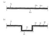
- FIG. 1is an enlarged cross-sectional view taken along the line AA of FIG. BB enlarged cross-sectional view of FIG.
- FIG. 2is an enlarged view of part C in FIG.
- (A) to (d)are process explanatory views explaining the manufacturing process of the first example of manufacturing the radome for the vehicle-mounted radar device of the first embodiment.
- (A) and (b)are process explanatory views explaining the manufacturing process of the heater layer used in the manufacturing process of the first example.
- (A) to (c)are process explanatory views explaining the manufacturing process of the 2nd example of manufacturing the radome for the vehicle-mounted radar apparatus of 1st Embodiment.
- (A) to (c)are process explanatory views explaining the manufacturing process of the heater layer used in the manufacturing process of the 2nd example.
- (A) to (c)are process explanatory views explaining the manufacturing process for manufacturing the radome for the vehicle-mounted radar device of the second embodiment.
- (A) and (b)are process explanatory views explaining the manufacturing process of the decorative heater layer used in the manufacturing process of the radome for the vehicle-mounted radar device of the second embodiment.
- radome 1 for an in-vehicle radar device according to the first embodimentAs shown in FIGS. 1 to 4, a transparent and electromagnetic wave transmitting front base material 2, a decorative layer 3, a heater layer 4, and an electromagnetic wave are used.
- the permeable rear base material 5is fixedly provided so as to be in close contact with each other in order from the surface side.
- the front base material 2 in the illustrated examplehas an elliptical shape when viewed from the front, and the mark symbol portion 10 constituting the design portion can be visually recognized from the surface side through the transparent front base material 2.
- R in FIG. 1is an electromagnetic wave transmission region.
- the shapes of the front base material 2 and the radome 1are arbitrary as long as they can be applied in addition to the elliptical shape, and may be, for example, a square, a rectangle, a trapezoid, a perfect circle, or a triangle.
- the transparent front base material 2 and the back base material 5are insulating and have electromagnetic wave transmission.
- the refractive index n defined based on the complex permittivityis consistent with each other, or the refractive index n is substantially the same or close to each other, for example, the front base material 2 and the back base material 5 are formed of the same material. Is suitable from the viewpoint of improving the transmission performance of electromagnetic waves.
- the numerical range of the refractive index n close to the front base material 2 and the rear base material 5it is preferable that the difference in the refractive index between the front base material 2 and the rear base material 5 is within the range of 0 to 10%.
- the refractive index nhere is a quantity defined as Equation 1 from the relative permittivity real part ⁇ r'and the relative permittivity imaginary part ⁇ r'. It is preferable that the magnitude of the dielectric tangent tan ⁇ defined as 2 is 0.1 or less, and the size of the real part of the relative permittivity is 3 or less. By making the size of the real part smaller than these values, it is possible to ensure the reduction of the refractive index and the internal loss required for the redome.
- the front base material 2 and the back base material 5appropriate materials such as synthetic resin, glass, and ceramics can be used within the scope of the present invention, but preferably an insulating synthetic resin is used. Good.
- the transparent front base material 2is preferably a colorless material or a colored material having a visible light transmittance of 50% or more in order to ensure good visibility.
- the material 2is an insulating transparent synthetic resin
- the materialis appropriate to the extent applicable, and is, for example, an acrylic resin such as polypropylene (PC) or polymethylmethacrylate (PMMA), or acrylonitrile-butadiene-styrene.
- PCpolypropylene
- PMMApolymethylmethacrylate
- the materialis appropriate to the extent applicable, and is, for example, acrylic such as acrylonitrile-ethylenepropyl rubber-styrene copolymer (AES) and polymethylmethacrylate (PMMA).
- acrylicsuch as acrylonitrile-ethylenepropyl rubber-styrene copolymer (AES) and polymethylmethacrylate (PMMA).
- AESacrylonitrile-ethylenepropyl rubber-styrene copolymer
- PMMApolymethylmethacrylate
- One type of resinpolycarbonate (PC), acrylonitrile-butadiene-styrene copolymer (ABS), acrylonitrile-styrene-acrylate copolymer (ASA), etc. can be used alone or in combination of two or more.
- Additivesmay be included.
- a decorative layer 3is provided in close contact with the back surface 21 of the front base material 2.
- the decorative layer 3 of the present embodimentis composed of an electromagnetic wave transmitting metal portion 31 and a colored portion 32, but the configuration of the decorative layer 3 is appropriate within the scope of the gist of the present invention.
- a decorative layer composed of only the electromagnetic wave transmitting metal portion or a decorative layer composed of only the colored portionfor example, a decorative layer composed of only the electromagnetic wave transmitting metal portion or a decorative layer composed of only the colored portion.
- an electromagnetic wave-transmissive discontinuous metal layer provided in the synthetic resinprovides an electromagnetic wave-transmissive and decorative insulating film that exhibits metallic luster, and a laminated synthetic resin that interferes with and reflects visible light to exhibit metallic luster. It is possible to use a decorative layer made of an electromagnetic wave transmitting and decorative insulating film such as a decorative insulating film, or a decorative layer formed by appropriately combining these.
- the electromagnetic wave transmitting metal portion 31 of the decorative layer 3is composed of a discontinuous metal layer having electromagnetic wave transmission and metallic luster, and has brilliant and integrated visibility. For example, on the back surface 21 of the front base material 2. It is formed by electroless plating, vapor deposition, spatter, etc.
- the electromagnetic wave transmitting metal portion 31is a discontinuous metal layer having a brilliant and integrated visibility, for example, nickel or nickel alloy, chromium or chromium alloy, cobalt or cobalt alloy, tin or tin alloy, copper or copper alloy. , Silver or silver alloy, palladium or palladium alloy, platinum or platinum alloy, rhodium or rhodium alloy, gold or gold alloy and the like.
- the electromagnetic wave transmitting metal portion 31shall be an appropriate electromagnetic wave transmitting metal portion within the scope of the present invention.
- a semiconductor layersuch as silicon or germanium formed by vapor deposition or sputtering, or a metal having a visible light reflectance of 50% or more (for example, gold, silver, copper, aluminum, platinum, palladium, etc.) It can be an alloy layer or the like with a bright metal such as iron, nickel, or chromium).
- a base layer for forming a modified surface that facilitates the formation of an electroless plating layer, etc.is transparent as necessary. It is also possible to provide a base layer such as a stratum.
- the colored portion 32has electromagnetic wave transmission property, and is formed on the back surface 21 of the front base material 2 by, for example, printing or painting with a painting mask.
- the colored portion 32is provided in close contact with the back surface 21 of the front base material 2 so as to be laminated on a part of the surface side of the electromagnetic wave transmitting metal portion 31.
- the electromagnetic wave transmitting metal portion 31is formed in a layer over the entire region where the back surface 21 of the base material 2 is exposed and the region where the colored portion 32 is provided, and the back surface 21 of the front base material 2 is exposed. It is provided in close contact with the colored portion 32.
- a recess 211is formed on the back surface 21 of the front base material 2 at a position corresponding to the mark symbol portion 10, and the decorative layer 3 partially protrudes toward the surface side in a cross-sectional view so as to imitate the recess 211. It is bent and formed.
- the electromagnetic wave transmitting metal portion 31 of the decorative layer 3is formed so as to partially project so as to imitate the recess 211, and the recess 211 is not provided with the colored portion 32, and only the electromagnetic wave transmitting metal portion 31 enters. It is provided.
- the colored portion 32 of the illustrated exampleis provided in close contact with the back surface 21 other than the recess 211 of the front base material 2.
- a recess 34is provided on the back surface 33 side of the decorative layer 3 at a position corresponding to the recess 211, and the heater layer 4 is formed by partially projecting and bending toward the surface side in a cross-sectional view so as to follow the recess 34. , The protruding portion 44 is arranged so as to be engaged with the recess 34.
- the heater layer 4has a heater element 41, and is formed from an insulating film 42, a heater element 41 fixed to the back surface side of the insulating film 42, and a protective film 43 formed so as to cover the heater element 41 from the back surface side. It is composed.
- the heater element 41can be made of an appropriate conductive material such as nichrome wire, iron chromium, copper, silver, carbon fiber, and a transparent conductive film such as an ITO film.
- the heat resistant temperature of the decorative layer 3is, for example, about 100 ° C.
- the heat resistant temperature of the front base material 2 such as PCis, for example, about 80 ° C., AES or the like.
- the heat-resistant temperature of the rear substrate 5is, for example, about 80 ° C.
- the radome 1 for an in-vehicle radar devicehas a structure having good heat resistance against a temperature rise of the heater element 41.
- the insulating film 42 and the protective film 43can be made of an applicable insulating material having appropriate electromagnetic wave transmittance, and for example, polycarbonate (PC), polyethylene (PE), polypropylene (PP, OPP), polyethylene terephthalate, etc. It is preferably formed of an insulating synthetic resin such as (PET), polyethylene terephthalate (PEN), vinyl chloride (PVC), polystyrene (PS), acrylic (AC), or polyetheretherketone (PEEK).
- the thickness of the insulating film 42is preferably 0.05 to 1.0 mm from the viewpoint of increasing the thermal conductivity to the front base material 2 and protecting the heater element 41.
- the refractive index n defined based on the complex permittivity of the front base material 2 and the rear base material 5is in agreement with each other, or the refractive index n is substantially the same or close to each other. Is suitable from the viewpoint of improving the transmission performance of electromagnetic waves.
- the numerical ranges of the refractive index n of the front base material 2 and the back base material 5 and the insulating film 42 close to each other and the refractive index n of the protective film 43 close to each otherinclude the refractive index of the front base material 2 and the back base material 5 and the insulating film.
- the difference between the bending coefficient of 42 and the refractive index of the protective film 43is within the range of 0 to 10%.
- These refractive indexes nare also quantities defined as Equation 1 from the relative permittivity real part ⁇ r'and the relative permittivity imaginary part ⁇ r'.
- the insulating film 42 and the protective film 43also have a viewpoint of transparency. It is preferable that the magnitude of the dielectric constant tangent tan ⁇ defined as Equation 2 from the ratio of the imaginary part and the real part at the applicable frequency is 0.1 or less.
- Both ends of the heater element 41 of the heater layer 4are electrically connected to the connector 6 and mechanically fixed, and power is supplied to the heater element 41 via the connector 6 so that the heater element 41 generates heat. It has become.
- the heater element 41 extending from the connector 6 in the illustrated exampleis wired so as to meander and fold back in the surface direction of the back surface 21 of the front base material 2 and is formed to extend in a series, and is wired adjacent to each other in the heater layer 4.
- the directions of the currents flowing through the heater elements 41 and 41are set to be substantially antiparallel or antiparallel to each other, and the electromagnetic waves radiated from the adjacent heater elements 41 and 41 have opposite phases, and the electromagnetic waves from the heater elements 41 It is possible to cancel the radiation and obtain better electromagnetic wave transmission performance.
- a convex portion 51is provided on the concave portion 45 on the back surface side of the heater layer 4 provided at a position corresponding to the concave portion 34 of the decorative layer 3, in other words, on the back surface side of the protruding portion 44.
- An electromagnetic wave transmitting rear substrate 5is provided on the back surface side of the heater layer 4 so as to engage with the heater layer 4.
- the radome 1 for an in-vehicle radar deviceis arranged in front of, for example, the in-vehicle radar device 100 and attached to a vehicle.
- the radome 1 for an in-vehicle radar device in the illustrated exampleis an emblem-shaped radome
- the radome for an in-vehicle radar device of the present inventioncan be configured by an appropriate vehicle-mounted component such as a bumper.
- the radome 1for an in-vehicle radar device of the first embodiment, for example, in the first example shown in FIG. 5, the radome 1 is placed on the front surface side so as to follow the recess 211 of the back surface 21 of the electromagnetic wave transmitting front base material 2.
- a partially protruding decorative layer 3is formed.
- the colored portion 32is formed in a predetermined area on the back surface 21 of the front base material 2 by printing or painting with a coating mask, and then electroless plating, vapor deposition, sputtering, or the like.
- the electromagnetic wave transmitting metal portion 31is formed over the entire surface including the inside of the recess 211 of the back surface 21 of the front base material 2 (see FIG. 5A).
- the heater layer 4 having the heater element 41 covered with the protective film 43is fixed to the decorative layer 3, and the heater layer 4 is arranged and fixed to the back surface 21 side of the front base material 2 (FIGS. 5B, 5). c) See).
- the adhesion of the heater layer 4 to the decorative layer 3is preferably performed by, for example, heat welding or adhesion with an adhesive.
- the heater element 41ais fixed to the back side of the flat insulating film 42a.
- the film body 7ais formed, and the protective film 43a is formed so as to cover the heater element 41a of the film body 7a from the opposite side to the insulating film 42a (see FIG. 6A).
- the heater element 41ais fixed to the insulating film 42a by using, for example, printing, vapor deposition, sputtering, plating, etching, MID, wire bonding, an inkjet, or a dispenser to form or draw the heater element 41a on the back surface side of the insulating film 42a. And do it.
- the protective film 43ais formed so as to cover the heater element 41a by, for example, a coating method such as printing by screen printing or pad printing, or coating by spray coating or the like. Further, the protective film 43a may be formed of a paint having an adhesive function such as a polyester-based paint to enhance the adhesion strength with the rear base material 5 at the time of injection molding described later.
- the flat film body 7awas deformed by air compaction so as to substantially follow the uneven shape on the back surface 21 side of the front base material 2 to form the heater layer 4 (see FIG. 6B), and was formed in this way.
- the heater layer 4is arranged on the back surface 21 side of the front base material 2 and fixed.
- the front base material 2 provided with the heater layer 4 having the heater element 41 on which the decorative layer 3 is formed and covered with the protective film 43is arranged in the mold, and corresponds to the recess 34 of the decorative layer 3.
- the convex portion 51is engaged with the concave portion 45 on the back surface side of the heater layer 4 provided at the position where the heater layer 4 is formed, in other words, the convex portion 51 substantially follows the uneven shape on the back surface 21 side of the front base material 2.
- An electromagnetic wave-transmitting rear substrate 5is formed on the back surface side of the heater layer 4 by injection molding and heat-welded to obtain a radome 1 for an in-vehicle radar device (see FIG. 5D).
- the protective film 43a and the protective film 43 after pneumatic molding thereofare formed with a paint having an adhesive function such as a polyester-based paint, and the decorative layer 3 is formed and covered with the protective film 43.
- the rear base material 5 having a shape substantially following the uneven shape on the back surface 21 side of the front base material 2is adhered to the protective film 43 having an adhesive function in the front base material 2 provided with the heater layer 4 having the heater element 41. It is also good to provide the radome 1 for an in-vehicle radar device.
- the decorative layer 3is fixed to the back surface 21 of the front base material 2 and the front surface side of the insulating film 42. It is also good to use the step of arranging and fixing the heater layer 4.
- a sheet-shaped heater layer 4 having three-dimensional unevennessis used.
- the heater element covered with the protective film 43by engaging the protrusion 44 formed on the surface side with a shape that partially protrudes to the surface side and the shape of the recess 211 and the electromagnetic wave transmitting metal portion 31 of the outer layer thereof.
- the heater layer 4 having 41 and having the decorative layer 3 fixed to the front surface side of the insulating film 42is fixed to the back surface 21 of the front base material 2, and the heater layer 4 is arranged on the back surface 21 side of the front base material 2. And stick (see FIG. 7B).
- the adhesion of the heater layer 4 or the decorative layer 3 to the back surface 21 of the front base material 2is preferably performed by, for example, heat welding or adhesion with an adhesive.
- the manufacturing step of FIG. 6AWhen forming the heater layer 4 in which the electromagnetic wave transmitting metal portion 31 and the colored portion 32 are attached to the insulating film 42, the heater element 41, and the protective film 43 used for fixing, for example, the manufacturing step of FIG. 6A.
- a flat film body 7b to which the heater element 41b is fixedis formed on the back side of the flat insulating film 42b, and the heater element 41b of the film body 7b is covered from the opposite side to the insulating film 42b.
- the protective film 43bmay also be formed of a paint having an adhesive function such as a polyester-based paint to enhance the adhesion strength with the rear base material 5 at the time of injection molding described later.
- an electromagnetic wave transmitting metal portion 31bis formed on the front surface side of the film body 7b by vapor deposition or sputtering, and a colored portion is formed outside a predetermined region of the electromagnetic wave transmitting metal portion 31b by printing or painting with a coating mask.
- a flat film body 7bis obtained by forming 32b and fixing the decorative layer 3b to the front surface side of the insulating film 42b (see FIG. 8B). It is also possible to perform a step of first forming the electromagnetic wave transmitting metal portion 31b and the colored portion 32b on the insulating film 42b, and then forming the heater element 41b and the protective film 43b.
- the flat film body 7bis deformed by pneumatic molding so as to substantially follow the uneven shape on the back surface 21 side of the front base material 2 to form the heater layer 4 to which the decorative layer 3 is attached (FIG. 8 (FIG. 8). c)), the heater layer 4 thus formed is arranged on the back surface 21 side of the front base material 2 and fixed.
- the front base material 2 provided with the heater layer 4 having the heater element 41 covered with the decorative layer 3 and the protective film 43is arranged in the mold, and a convex portion is formed in the concave portion 45 on the back surface side of the heater layer 4. 51 is engaged, in other words, the rear base material 5 for electromagnetic wave transmission is injection-molded on the back side of the heater layer 4 so as to substantially follow the uneven shape on the back surface 21 side of the front base material 2. It is formed and heat-welded to obtain a radome 1 for an in-vehicle radar device (see FIG. 7C).
- the protective film 43a and the protective film 43 after pneumatic molding thereofare formed with a paint having an adhesive function such as a polyester-based paint, and the decorative layer 3 is formed and covered with the protective film 43.
- the rear base material 5 having a shape substantially following the uneven shape on the back surface 21 side of the front base material 2is adhered to the protective film 43 having an adhesive function in the front base material 2 provided with the heater layer 4 having the heater element 41. It is also good to provide the radome 1 for an in-vehicle radar device.
- the decorative layer constituting the design portion of the emblem or the likeis formed through the transparent front base material 2. Good visibility of 3 can be ensured. Further, since the radome 1 is provided with the decorative layer 3 and the heater layer 4 in close contact with each other without providing a gap or a base material between the decorative layer 3 and the heater layer 4, electromagnetic wave transmission is improved. can do. Further, since the radome is provided with the front base material 2 and the decorative layer 3 without providing another base material between the surface 22 of the transparent front base material 2 and the heater layer 4, the heater layer is provided.
- the heat conduction efficiency from 4 to the surface 22 of the front base material 2can be increased, and the snow and ice adhering to the outer surface of the radome 1 can be reliably melted. Further, since the radome is formed with the front base material 2 installed between the surface 22 of the front base material 2 and the heater layer 4, the heating of the heater layer 4 is thermally diffused by the thickness and spread of the front base material 2. , Snow melting with high uniformity can be performed over the entire surface 22 of the front base material 2. Further, since the base material is not provided between the decorative layer 3 and the heater layer 4, the molding process of the base material during this period can be eliminated, and the production can be performed with higher production efficiency.
- the insulation property of the radome 1 by the insulating film 42it is possible to prevent the decorative layer 3 from being electrically connected to the heater element 41 regardless of the configuration of the decorative layer 3, and the decorative layer 3 can be prevented from being electrically connected. It is possible to surely prevent the electromagnetic wave transmission from being lowered due to the continuity.
- the position of the heater element 41can be prevented from being displaced, and the heater element 41 can be protected by the insulating film 42.
- the insulating film 42functions as a base for fixing the heater element 41, and can increase the fixing strength of the heater element 41 to the decorative layer 3.
- the heater layer 4 of the intermediate productcan be obtained by forming the heater element 41 based on the insulating film 42, it can be formed by using various manufacturing means, and the applicable manufacturing means can be used. Diversification can be achieved.
- the protective film 43 that covers the heater element 41 from the back surface sidethe front surface side of the heater element 41 can be protected by the insulating film 42, and at the same time, the back surface side thereof can be protected by the protective film 43. Therefore, it is possible to prevent the heater element 41 from being damaged, for example, when the electromagnetic wave transmitting rear base material 5 is formed on the back surface side of the heater layer 4 by injection molding.
- the rear base material 5by injection molding so as to substantially follow the uneven shape on the back surface 21 side of the front base material 2, the uneven shape and the rear base of the front base material 2, the decorative layer 3, and the heater layer 4 are formed.
- a rear base material 5 having a high fixing strength in which the unevenness of the material 5 is engaged and fixedcan be provided on the back surface side.
- a heater layer 4composed of an insulating film 42 and a heater element 41 fixed to the back surface side thereof is used, and the back surface 21 of the front base material 2 is used.
- the insulating film 42 of the heater layer 4 and the heater element 41are provided so as to be easily aligned with the front base material 2 and the decorative layer 3. It is possible to facilitate the manufacturing operation.
- the insulating film 42functions as a base for fixing the heater element 41, and can increase the fixing strength of the heater element 41 to the decorative layer 3 formed on the back surface 21 side of the front base material 2.
- the flat film body 7ais deformed by air compaction so as to substantially follow the uneven shape on the back surface 21 side of the front base material 2 to form the heater layer 4, so that the heater element 41 is formed on the back surface side of the insulating film 42.
- the heater layer 4can be formed only by fixing and deforming the heater layer 4, and the manufacturing process of the heater layer 4 can be facilitated and made more efficient.
- the heater layer 4 having a shape accurately imitated by the unevenness on the back surface 21 side of the front base material 2can be formed, and the heater layer has a shape adapted to the uneven shape on the back surface 21 side of the front base material 2. 4 can be formed. Further, by forming the decorative layer 3 on the back surface 21 side of the front base material 2, the accuracy of the formation position of the decorative layer 3 with respect to the front base material 2 can be improved.
- the heater layer 4 to which the decorative layer 3 is fixed to the front side of the insulating film 42is arranged on the back surface 21 of the front base material 2.
- the radome 1 having the decorative layer 3can be obtained without performing the step of forming the decorative layer 3 on the back surface 21 side of the front base material 2.
- the heater layer 4 formed by aligning the decorative layer 3 and the heater element 41 in advancecan be fixed to the back surface 21 of the front base material 2 to manufacture the radome 1, facilitating the manufacturing work. Can be done.
- the insulating film 42functions as a base for fixing the heater element 41, and can increase the fixing strength of the heater element 41 to the decorative layer 3.
- the flat film body 7bis deformed by pneumatic molding so as to substantially follow the uneven shape on the back surface 21 side of the front base material 2 to form the heater layer 4 to which the decorative layer 3 is attached, thereby forming an insulating film.
- the heater layer 4 and the decorative layer 3can be formed only by fixing the heater element 41b to the back side of the 42b and fixing the decorative layer 3b to the front side of the insulating film 42b and deforming the heater layer 4, The manufacturing process of the decorative layer 3 can be facilitated and made more efficient. Further, the heater layer 4 to which the decorative layer 3 having a shape accurately imitated by the unevenness on the back surface 21 side of the front base material 2 can be formed, and the unevenness on the back surface 21 side of the various front base material 2 can be formed.
- the heater layer 4it is possible to form the heater layer 4 to which the decorative layer 3 having a shape adapted to the shape is attached. Further, in the step of forming the flat film body 7b, the heater element 41b and the decorative layer 3b can be formed by the same printing step or the like, so that the moving work between the steps can be reduced and the steps can be reduced. It is possible to suppress the mixing of foreign substances that cause poor appearance, which tends to occur due to movement between them.
- radome 1p for an in-vehicle radar device according to the second embodimentAs shown in FIG. 9, a transparent and electromagnetic wave transmitting front base material 2, a decorative heater layer 4p, and an electromagnetic wave transmitting rear base are used.
- the members 5are fixedly provided so as to be in close contact with each other in order from the surface side.
- the configurations of the front base material 2 and the rear base material 5are the same as those of the first embodiment.
- the decorative heater layer 4pis an electromagnetic wave-transmitting discontinuous metal layer provided on the synthetic resin, which is an electromagnetic wave-transmitting decorative insulating film showing metallic luster, and a laminated synthetic resin that interferes with and reflects visible light to form a metal. It is composed of an electromagnetic wave transmitting decorative insulating film 42p such as an electromagnetic wave transmitting decorative insulating film showing gloss, a heater element 41, and a protective film 43 formed so as to cover the heater element 41 from the back side. To.
- the decorative heater layer 4pis arranged and fixed to the back surface side of the front base material 2, and is partially projected and bent toward the front surface side in a cross-sectional view so as to follow the recess 211 of the back surface 21 of the front base material 2. It is formed and is arranged so that the protruding portion 44p is engaged with the recess 211.
- the configuration of the heater element 41 and the protective film 43 of the decorative heater layer 4pis the same as that of the first embodiment. Further, the same material as that of the insulating film 42 of the first embodiment can be used for the film body of the decorative insulating film 42p. Further, as in the first embodiment, the decorative insulating film 42p and the protective film 43 have the front base material 2 and the back base material 5 and the refractive index n defined based on the complex permittivity mutually consistent with each other. Or, it is preferable to use those having substantially the same or close refractive indexes n from the viewpoint of improving the transmission performance of electromagnetic waves.
- the convex portion 51is engaged with the concave portion 45p on the back side of the decorative heater layer 4p so that the convex portion 51 is made to transmit electromagnetic waves to the back side of the decorative heater layer 4p.
- the rear base material 5is provided.
- Other configurations of the radome 1p for the vehicle-mounted radar device of the second embodimentare the same as those of the radome 1 for the vehicle-mounted radar device of the first embodiment.
- the decorative insulating film 42p, the heater element 41 fixed to the back side of the insulating film 42p, and the heater element 41are covered from the back side.
- the decorative heater layer 4p to be providedis fixed to the front base material 2, and the heater layer 4p is arranged and fixed to the back surface 21 side of the front base material 2 (see FIGS. 10A and 10B).
- the adhesion of the heater layer 4p to the back surface 21 of the front base material 2is preferably performed by, for example, heat welding or adhesion with an adhesive.
- the decorative heater layer 4pcomposed of the decorative insulating film 42p used for fixing, the heater element 41, and the protective film 43, for example, the back side of the flat decorative insulating film 42q.
- a flat film body 7q to which the heater element 41q is fixedis formed, and the protective film 43q is formed so as to cover the heater element 41q of the film body 7q from the opposite side to the decorative insulating film 42q (FIG. 11 (a)). )reference).
- the protective film 43qis formed so as to cover the heater element 41q by, for example, a coating method such as printing by screen printing, pad printing, or painting by spray painting or the like. Further, the protective film 43q may be formed of a paint having an adhesive function such as a polyester-based paint to enhance the adhesion strength with the rear base material 5 at the time of injection molding described later.
- This flat film body 7qis deformed by air compaction so as to substantially follow the uneven shape on the back surface 21 side of the front base material 2 to form a decorative heater layer 4p (see FIG. 11B).
- the decorative heater layer 4p thus formedis arranged on the back surface 21 side of the front base material 2 and fixed.
- the front base material 2 provided with the decorative heater layer 4pis arranged in the mold so that the convex portion 51 is engaged with the concave portion 45p on the back surface side of the heater layer 4p, in other words.
- An electromagnetic wave-transmitting rear base material 5is formed by injection molding on the back side of the decorative heater layer 4p so as to substantially follow the uneven shape on the back surface 21 side of the front base material 2, and is heat-welded to the vehicle-mounted radar. Obtain a radome 1p for the device (see FIG. 10 (c)).
- the protective film 43q and the protective film 43 after pneumatic molding thereofare formed of a paint having an adhesive function such as a polyester-based paint, and the front base material 2 provided with the decorative heater layer 4p.
- a radome 1p having a decorative insulating film 42p on the surface side of the heater element 41decorations constituting the design portion of the emblem or the like are formed through the transparent front base material 2. Good visibility of the portion can be ensured. Further, since a radome 1p having a heater layer 4p in which the decorative portion and the heater element 41 are integrated is formed without providing a gap portion or a base material between the decorative insulating film 42p and the heater element 41, electromagnetic waves are generated. Transparency can be improved.
- the radome 1pis not provided with another base material between the surface 22 of the transparent front base material 2 and the heater layer 4p, heat conduction from the heater layer 4p to the surface 22 of the front base material 2 The efficiency can be improved, and the snow and ice adhering to the outer surface of the radome 1p can be reliably melted. Further, since the radome 1p in which the front base material 2 is installed between the surface 22 of the front base material 2 and the heater layer 4p is formed, the heating of the heater layer 4p is thermally diffused by the thickness and spread of the front base material 2. Therefore, highly uniform snow melting can be performed over the entire surface 22 of the front base material 2. Further, since the base material is not provided between the decorative portion and the heater layer 4p, the molding process of the base material during this period can be eliminated, and the production can be performed with higher production efficiency.
- the decorative insulating film 42pfunctions as a base for fixing the heater element 41, and can increase the fixing strength of the heater element 41 to the front base material 2.
- the decorative heater layer 4p of the intermediate productcan be obtained by forming the heater element 41 based on the decorative insulating film 42, it can be formed by using various manufacturing means. Therefore, it is possible to diversify the applicable manufacturing means. Further, by forming the decorative portion by using the decorative insulating film 42p, it is possible to improve the efficiency of the manufacturing process by eliminating the step of separately forming the decorative layer.
- the decorative heater layer 4pcan be formed only by deforming the flat film body 7q in which the heater element 41 is fixed to the back side of the decorative insulating film 42q, and the decorative heater layer 4p can be formed. It is possible to simplify and improve the efficiency of the manufacturing process of the above. Further, the flat film body 7q is deformed by air compaction so as to substantially follow the uneven shape on the back surface 21 side of the front base material 2 to form the decorative heater layer 4P, whereby the back surface of the front base material 2 is formed. A decorative heater layer 4p having a shape that accurately follows the unevenness on the 21 side can be formed, and a decorative heater layer having a shape adapted to the uneven shape on the back surface 21 side of various front base materials 2 can be formed. 4p can be formed.
- the second embodimenthas a corresponding effect from the configuration corresponding to the first embodiment.
- the heater layer 4 in the in-vehicle radar device radome 1 of the above embodimenthas a structure having a protective film 43 that covers the heater element 41 from the back side, but a heater layer 4 without the protective film 43 is also possible.
- the heater layer in the present inventionincludes an appropriate heater layer composed of an insulating film and a heater element fixed to the back surface side of the insulating film.
- the directions of the currents flowing through the heater elements wired adjacent to each otherare substantially antiparallel or antiparallel to each other, but they are wired adjacent to each other. It is also possible to configure the direction of the current flowing through the heater element to be substantially antiparallel or not antiparallel to each other.
- the wiring pattern and wiring configuration of the heater element in the present inventionare not limited to the wiring configuration of the heater element 41, and are appropriate within the scope of the gist of the present invention. It may be configured to be wired, or the heater element may be wired so as to extend substantially radially from the center.
- the electromagnetic wave of the radar targeted by the radome for the in-vehicle radar device in the present inventionis appropriate within an applicable range, and the 24/26 GHz band, 76/77 GHz band, 77/81 GHz band, etc., which are practically used as in-vehicle radars, etc.
- the present inventioncan be applied to electromagnetic waves for radar other than these.
- the present inventioncan be similarly applied when a radar having a shorter wavelength is put into practical use.
- the present inventioncan be used when manufacturing a radome for an in-vehicle radar device.
- Electromagnetic wave transmitting metal parts32, 32b ... Colored part 33 ... Back side 34 ... Recesses 4, 4p ... Heater layers 41, 41a, 41b, 41q ... Heater elements 42, 42a, 42b, 42p, 42q ... Insulating film 43, 43a, 43b, 43q ... Protective film 44, 44p ... Protruding parts 45, 45p ... Recesses 5 ... Rear base material 51 ... Convex part 6 ... Connector 7a, 7b, 7q ... Flat film body 10 ... Mark symbol part 100 ... In-vehicle radar device R ... Electromagnetic wave transmission region
Landscapes
- Engineering & Computer Science (AREA)
- Radar, Positioning & Navigation (AREA)
- Remote Sensing (AREA)
- Mechanical Engineering (AREA)
- Physics & Mathematics (AREA)
- Manufacturing & Machinery (AREA)
- Computer Networks & Wireless Communication (AREA)
- General Physics & Mathematics (AREA)
- Electromagnetism (AREA)
- Details Of Aerials (AREA)
- Radar Systems Or Details Thereof (AREA)
- Vehicle Interior And Exterior Ornaments, Soundproofing, And Insulation (AREA)
- Vehicle Waterproofing, Decoration, And Sanitation Devices (AREA)
- Injection Moulding Of Plastics Or The Like (AREA)
Abstract
Description
Translated fromJapanese本発明は、車載レーダー装置の前側に設けられる車載レーダー装置用レドームに係り、特に融雪機能を有する車載レーダー装置用レドームの製造方法に関する。The present invention relates to a radome for an in-vehicle radar device provided on the front side of the in-vehicle radar device, and particularly relates to a method for manufacturing a radome for an in-vehicle radar device having a snow melting function.
従来、車載レーダー装置用レドームとして、必要な電磁波の透過性の確保を図りつつ、融雪機能を発揮するレドームが知られている。このようなレドームとして、加飾層の後側にヒーター層を設け、加飾層の良好な視認性を確保できる特許文献1のレドームがある。特許文献1のレドームは、透明基板と、透明基板の後側に配置される第1基材及び第2基材を有し、透明基板と第1基材の間に加飾層が形成され、第1基材と第2基材がヒーター層を前後から挟み込んで密封するようにして相互に接合されるものであり、表面側から順に透明基板、加飾層、第1基材、ヒーター層、第2基材が設けられる構造になっている。Conventionally, as a radome for an in-vehicle radar device, a radome that exhibits a snow melting function while ensuring the necessary electromagnetic wave transmission is known. As such a radome, there is a radome of
また、特許文献1には、従来例のレドームとして、表面側から順に透明基板、加飾層、空隙部、ヒーター層、基材が設けられる構造も開示されている。この従来例のレドームは、透明基板及び基材の比誘電率と大きく異なる空隙部内の空気の比誘電率により、電磁波透過性能が低下することが指摘されている(特許文献1の段落[0004]、[0010]、図10(b)参照)。Further,
ところで、特許文献1のレドームは、上記従来例のレドームの空隙部に相当する部位に第2基材と同一樹脂材料の第1基材を配置する構造により、電磁波透過性能の低下を抑制することが可能である。しかしながら、特許文献1のレドームは、透明基板の表面とヒーター層との間に透明基板、加飾層、第1基材が配置される構造のため、ヒーター層から雪が付着する透明基板の表面までの距離が長くなり、熱伝導効率が低下するという問題がある。By the way, the radome of
本発明は上記課題に鑑み提案するものであり、エンブレムの意匠部等を構成する加飾部分の良好な視認性の確保、電磁波透過性の向上を図ることができると共に、高い熱伝導効率でレドームの外表面に付着した雪を確実に融雪することができる車載レーダー装置用レドームの製造方法を提供することを目的とする。The present invention has been proposed in view of the above problems, and it is possible to ensure good visibility of the decorative portion constituting the design portion of the emblem, improve electromagnetic wave transmission, and achieve a radome with high heat conduction efficiency. It is an object of the present invention to provide a method for manufacturing a radome for an in-vehicle radar device capable of surely melting snow adhering to the outer surface of the vehicle.
本発明の車載レーダー装置用レドームの製造方法は、透明で電磁波透過性の前基材と、加飾層と、ヒーター層が表面側から順に密接して設けられる車載レーダー装置用レドームの製造方法であって、前記前基材の背面側に、絶縁フィルムと前記絶縁フィルムの背面側に固着されたヒーターエレメントから構成される前記ヒーター層を配置して固着するヒーター層固着工程を備えることを特徴とする。
これによれば、ヒーター層の表面側に加飾層が設けられるレドームを得ることにより、透明な前基材を介して、エンブレムの意匠部等を構成する加飾層の良好な視認性を確保することができる。また、加飾層とヒーター層との間に空隙部や基材が設けられずに、加飾層とヒーター層が密接して設けられるレドームになるため、電磁波透過性を向上することができる。また、透明な前基材の表面とヒーター層との間に、別の基材が設けられずに、前基材と加飾層が設けられるレドームとなることから、ヒーター層から前基材の表面への熱伝導効率を高めることができ、レドームの外表面に付着した雪や氷を確実に融雪することができる。また、前基材の表面とヒーター層との間に前基材が設置されたレドームとなることから、前基材の厚みや広がりでヒーター層の加熱を熱拡散して、前基材の表面全体に亘って均一性の高い融雪を行うことができる。また、加飾層とヒーター層との間に基材を設けないことから、この間の基材の成形工程を無くすことができ、より高い製造効率で製造することができる。また、レドームの絶縁フィルムによる絶縁性担保により、加飾層の構成に拘わらず、ヒーターエレメントへの通電で加飾層に導通が発生することを防止でき、加飾層の導通で電磁波透過性が低下することを確実に防止できる。また、絶縁フィルムにヒーターエレメントを固着することにより、ヒーターエレメントの位置ズレを防止できると共に、絶縁フィルムでヒーターエレメントを保護することもできる。また、絶縁フィルムはヒーターエレメントを固着する下地として機能し、ヒーターエレメントの加飾層への固着強度を高めることができる。また、中間品のヒーター層は、絶縁フィルムを基にしてヒーターエレメントを形成して得ることができることから、多様な製造手段を用いて形成することが可能となり、適用可能な製造手段の多様化を図ることができる。The method for manufacturing a radome for an in-vehicle radar device of the present invention is a method for manufacturing a radome for an in-vehicle radar device in which a transparent and electromagnetic wave-transmitting front base material, a decorative layer, and a heater layer are provided in close contact with each other in order from the surface side. The present invention is characterized by comprising a heater layer fixing step of arranging and fixing the heater layer composed of an insulating film and a heater element fixed to the back side of the insulating film on the back side of the front base material. To do.
According to this, by obtaining a radome in which the decorative layer is provided on the surface side of the heater layer, good visibility of the decorative layer constituting the design portion of the emblem or the like is ensured through the transparent front base material. can do. Further, since the radome is provided with the decorative layer and the heater layer in close contact with each other without providing a gap or a base material between the decorative layer and the heater layer, electromagnetic wave transmission can be improved. Further, since the radome is provided with the front base material and the decorative layer without providing another base material between the surface of the transparent front base material and the heater layer, the heater layer to the front base material can be used. The efficiency of heat conduction to the surface can be increased, and the snow and ice adhering to the outer surface of the radome can be reliably melted. In addition, since the radome is a radome in which the front base material is installed between the surface of the front base material and the heater layer, the heating of the heater layer is thermally diffused by the thickness and spread of the front base material, and the surface of the front base material is used. It is possible to melt snow with high uniformity throughout. Further, since the base material is not provided between the decorative layer and the heater layer, the molding process of the base material during this period can be eliminated, and the production can be performed with higher production efficiency. In addition, by ensuring the insulation with the insulating film of the radome, it is possible to prevent the decorative layer from being conductive when the heater element is energized, regardless of the configuration of the decorative layer, and the electromagnetic wave transmission is increased by the conduction of the decorative layer. It can be surely prevented from being lowered. Further, by fixing the heater element to the insulating film, it is possible to prevent the heater element from being displaced, and it is also possible to protect the heater element with the insulating film. Further, the insulating film functions as a base for fixing the heater element, and can increase the fixing strength of the heater element to the decorative layer. Further, since the heater layer of the intermediate product can be obtained by forming a heater element based on the insulating film, it can be formed by using various manufacturing means, and the applicable manufacturing means can be diversified. Can be planned.
本発明の車載レーダー装置用レドームの製造方法は、前記ヒーターエレメントを背面側から覆うようにして保護膜を形成し、前記保護膜で覆われた前記ヒーターエレメントを有する前記ヒーター層を前記前基材の背面側に配置して固着することを特徴とする。
これによれば、ヒーターエレメントの前面側を絶縁フィルムで保護すると同時に、その背面側を保護膜で保護することができる。従って、例えばヒーター層の背面側に電磁波透過性の後基材を射出成形で形成する場合等に、ヒーターエレメントが損傷することを防止することができる。In the method for manufacturing a radome for an in-vehicle radar device of the present invention, a protective film is formed so as to cover the heater element from the back surface side, and the heater layer having the heater element covered with the protective film is formed on the front base material. It is characterized in that it is arranged and fixed on the back side of the.
According to this, the front side of the heater element can be protected by the insulating film, and at the same time, the back side thereof can be protected by the protective film. Therefore, it is possible to prevent the heater element from being damaged, for example, when an electromagnetic wave transmitting rear substrate is formed on the back surface side of the heater layer by injection molding.
本発明の車載レーダー装置用レドームの製造方法は、前記ヒーター層が固着された前記前基材を金型内に配置し、前記前基材の背面側の凹凸形状に略倣うようにして、前記ヒーター層の背面側に電磁波透過性の後基材を射出成形で形成する後基材形成工程を備えることを特徴とする。
これによれば、前基材の背面側の凹凸形状に略倣うようにして後基材を射出成形で形成することにより、前基材、加飾層、ヒーター層の凹凸と後基材の凹凸が係合固着した高い固着強度の後基材を背面側に設けることができる。In the method for manufacturing a radome for an in-vehicle radar device of the present invention, the front base material to which the heater layer is fixed is arranged in a mold and substantially follows the uneven shape on the back surface side of the front base material. The back surface side of the heater layer is provided with a post-base material forming step of forming a back base material transparent to electromagnetic waves by injection molding.
According to this, by forming the rear base material by injection molding so as to substantially follow the uneven shape on the back surface side of the front base material, the unevenness of the front base material, the decorative layer, the heater layer and the unevenness of the rear base material are formed. A base material can be provided on the back side after a high fixing strength in which the members are engaged and fixed.
本発明の車載レーダー装置用レドームの製造方法は、前記前基材の背面側に前記加飾層を形成する工程を行った後、前記加飾層の背面に前記ヒーター層を固着する前記ヒーター層固着工程を行うことを特徴とする。
これによれば、絶縁フィルムとその背面側に固着されたヒーターエレメントから構成されるヒーター層を用い、前基材の背面側に形成された加飾層の背面にヒーター層を固着することにより、前基材や加飾層と容易に位置合わせしてヒーター層の絶縁フィルムとヒーターエレメントを設けることができ、製造作業を容易化することができる。また、絶縁フィルムはヒーターエレメントを固着する下地として機能し、前基材の背面側に形成された加飾層へのヒーターエレメントの固着強度を高めることができる。また、前基材の背面側に加飾層を形成することにより、前基材に対する加飾層の形成位置の精度を高めることができる。In the method for manufacturing a radome for an in-vehicle radar device of the present invention, the heater layer is fixed to the back surface of the decoration layer after performing the step of forming the decoration layer on the back surface side of the front base material. It is characterized by performing a fixing step.
According to this, a heater layer composed of an insulating film and a heater element fixed to the back side thereof is used, and the heater layer is fixed to the back surface of the decorative layer formed on the back side of the front base material. The insulating film and heater element of the heater layer can be easily aligned with the front base material and the decorative layer, and the manufacturing work can be facilitated. Further, the insulating film functions as a base for fixing the heater element, and can increase the fixing strength of the heater element to the decorative layer formed on the back surface side of the front base material. Further, by forming the decorative layer on the back surface side of the front base material, the accuracy of the formation position of the decorative layer with respect to the front base material can be improved.
本発明の車載レーダー装置用レドームの製造方法は、絶縁フィルムの背面側にヒーターエレメントを固着した平面状のフィルム体を形成する工程と、前記平面状のフィルム体を圧空成形で前記前基材の背面側の凹凸形状に略倣うように変形させて前記ヒーター層を形成する工程を備えることを特徴とする。
これによれば、絶縁フィルムの背面側にヒーターエレメントを固着して変形するだけでヒーター層を形成することができ、ヒーター層の製造工程を容易化、効率化することができる。また、平面状のフィルム体を圧空成形で前基材の背面側の凹凸形状に略倣うように変形させてヒーター層を形成することにより、前基材の背面側の凹凸により正確に倣った形状のヒーター層を形成することができると共に、多様な前基材の背面側の凹凸形状に適応した形状のヒーター層を形成することができる。The method for manufacturing a radome for an in-vehicle radar device of the present invention includes a step of forming a flat film body in which a heater element is fixed to the back side of an insulating film, and a pressure molding of the flat film body to form a front base material. It is characterized by comprising a step of forming the heater layer by deforming it so as to substantially follow the uneven shape on the back surface side.
According to this, the heater layer can be formed only by fixing and deforming the heater element on the back surface side of the insulating film, and the manufacturing process of the heater layer can be facilitated and made more efficient. Further, by forming a heater layer by deforming a flat film body by pneumatic molding so as to substantially follow the uneven shape on the back side of the front base material, a shape that accurately follows the uneven shape on the back side of the front base material. The heater layer can be formed, and the heater layer having a shape adapted to the uneven shape on the back surface side of various front substrates can be formed.
本発明の車載レーダー装置用レドームの製造方法は、前記前基材の背面に、前記絶縁フィルムの前面側に前記加飾層が固着された前記ヒーター層を配置して固着する前記ヒーター層固着工程を行うことを特徴とする。
これによれば、前基材の背面側への加飾層を形成する工程を行わずに、加飾層を有するレドームを得ることができる。また、加飾層とヒーターエレメントが予め位置合わせして形成されたヒーター層を前基材の背面に固着してレドームを製造することができ、製造作業を容易化することができる。また、絶縁フィルムはヒーターエレメントを固着する下地として機能し、ヒーターエレメントの加飾層への固着強度を高めることができる。The method for manufacturing a radome for an in-vehicle radar device of the present invention is a heater layer fixing step of arranging and fixing the heater layer to which the decorative layer is fixed on the front side of the insulating film on the back surface of the front base material. It is characterized by performing.
According to this, it is possible to obtain a radome having a decorative layer without performing a step of forming a decorative layer on the back surface side of the front base material. Further, the heater layer formed by aligning the decorative layer and the heater element in advance can be fixed to the back surface of the front base material to manufacture the radome, and the manufacturing work can be facilitated. Further, the insulating film functions as a base for fixing the heater element, and can increase the fixing strength of the heater element to the decorative layer.
本発明の車載レーダー装置用レドームの製造方法は、絶縁フィルムの背面側にヒーターエレメントを固着し且つ前記絶縁フィルムの前面側に加飾層を固着した平面状のフィルム体を形成する工程と、前記平面状のフィルム体を圧空成形で前記前基材の背面側の凹凸形状に略倣うように変形させて前記加飾層が併設された前記ヒーター層を形成する工程を備えることを特徴とする。
これによれば、絶縁フィルムの背面側にヒーターエレメントを固着し且つ絶縁フィルムの前面側に加飾層を固着して変形するだけでヒーター層、加飾層を形成することができ、ヒーター層、加飾層の製造工程を容易化、効率化することができる。また、平面状のフィルム体を圧空成形で前基材の背面側の凹凸形状に略倣うように変形させて加飾層が併設されたヒーター層を形成することにより、前基材の背面側の凹凸により正確に倣った形状の加飾層が併設されたヒーター層を形成することができると共に、多様な前基材の背面側の凹凸形状に適応した形状の加飾層が併設されたヒーター層を形成することができる。また、平面状のフィルム体を形成する工程において、ヒーターエレメントと加飾層を同一の印刷工程等で形成することが可能であり、工程間の移動作業を減らすことができると共に、工程間の移動で発生し易い外観不良の原因となる異物混入を抑制することができる。The method for manufacturing a radome for an in-vehicle radar device of the present invention includes a step of forming a flat film body in which a heater element is fixed to the back side of an insulating film and a decorative layer is fixed to the front side of the insulating film. It is characterized by comprising a step of forming the heater layer to which the decorative layer is attached by deforming a flat film body by pneumatic molding so as to substantially follow the uneven shape on the back surface side of the front base material.
According to this, the heater layer and the decorative layer can be formed only by fixing the heater element to the back side of the insulating film and fixing the decorative layer to the front side of the insulating film and deforming the heater layer. The manufacturing process of the decorative layer can be facilitated and made more efficient. Further, the flat film body is deformed by air compaction so as to substantially follow the uneven shape on the back side of the front base material to form a heater layer with a decorative layer, thereby forming a heater layer on the back side of the front base material. It is possible to form a heater layer with a decorative layer having a shape that accurately follows the unevenness, and a heater layer with a decorative layer having a shape adapted to the uneven shape on the back side of various front substrates. Can be formed. Further, in the process of forming a flat film body, the heater element and the decorative layer can be formed by the same printing process or the like, so that the movement work between the processes can be reduced and the movement between the processes can be reduced. It is possible to suppress the mixing of foreign substances that cause poor appearance, which is likely to occur in the above.
本発明の車載レーダー装置用レドームの製造方法は、透明で電磁波透過性の前基材と、加飾性のヒーター層が表面側から順に密接して設けられる車載レーダー装置用レドームの製造方法であって、前記前基材の背面側に、加飾性絶縁フィルムと前記加飾性絶縁フィルムの背面側に固着されたヒーターエレメントから構成される前記ヒーター層を配置して固着するヒーター層固着工程を備えることを特徴とする。
これによれば、ヒーターエレメントの表面側に加飾性絶縁フィルムを有するレドームを得ることにより、透明な前基材を介して、エンブレムの意匠部等を構成する加飾部分の良好な視認性を確保することができる。また、加飾性絶縁フィルムとヒーターエレメントとの間に空隙部や基材が設けられずに、加飾部分とヒーターエレメントが一体化したヒーター層を有するレドームになるため、電磁波透過性を向上することができる。また、透明な前基材の表面とヒーター層との間に、別の基材が設けられないレドームとなることから、ヒーター層から前基材の表面への熱伝導効率を高めることができ、レドームの外表面に付着した雪や氷を確実に融雪することができる。また、前基材の表面とヒーター層との間に前基材が設置されたレドームとなることから、前基材の厚みや広がりでヒーター層の加熱を熱拡散して、前基材の表面全体に亘って均一性の高い融雪を行うことができる。また、加飾部分とヒーター層との間に基材を設けないことから、この間の基材の成形工程を無くすことができ、より高い製造効率で製造することができる。また、加飾性絶縁フィルムにヒーターエレメントを固着することにより、ヒーターエレメントの位置ズレを防止できると共に、加飾性絶縁フィルムでヒーターエレメントを保護することもできる。また、加飾性絶縁フィルムはヒーターエレメントを固着する下地として機能し、ヒーターエレメントの前基材への固着強度を高めることができる。また、中間品の加飾性のヒーター層は、加飾性の絶縁フィルムを基にしてヒーターエレメントを形成して得ることができることから、多様な製造手段を用いて形成することが可能となり、適用可能な製造手段の多様化を図ることができる。また、加飾性絶縁フィルムを用いて加飾部分を構成することにより、別途に加飾層を形成する工程を無くして製造工程を効率化することができる。The method for manufacturing a radome for an in-vehicle radar device of the present invention is a method for manufacturing a radome for an in-vehicle radar device in which a transparent and electromagnetic wave-transmitting front base material and a decorative heater layer are provided in close contact with each other in order from the surface side. The heater layer fixing step of arranging and fixing the heater layer composed of the decorative insulating film and the heater element fixed to the back side of the decorative insulating film on the back side of the front base material is performed. It is characterized by being prepared.
According to this, by obtaining a radome having a decorative insulating film on the surface side of the heater element, good visibility of the decorative portion constituting the design portion of the emblem or the like is obtained through the transparent front base material. Can be secured. Further, since the radome has a heater layer in which the decorative portion and the heater element are integrated without providing a gap or a base material between the decorative insulating film and the heater element, electromagnetic wave transmission is improved. be able to. Further, since the radome is formed so that another base material is not provided between the surface of the transparent front base material and the heater layer, the heat conduction efficiency from the heater layer to the surface of the front base material can be improved. The snow and ice adhering to the outer surface of the radome can be reliably melted. In addition, since the radome is a radome in which the front base material is installed between the surface of the front base material and the heater layer, the heating of the heater layer is thermally diffused by the thickness and spread of the front base material, and the surface of the front base material is used. It is possible to melt snow with high uniformity throughout. Further, since the base material is not provided between the decorative portion and the heater layer, the molding process of the base material during this period can be eliminated, and the production can be performed with higher production efficiency. Further, by fixing the heater element to the decorative insulating film, it is possible to prevent the heater element from being displaced, and it is also possible to protect the heater element with the decorative insulating film. Further, the decorative insulating film functions as a base for fixing the heater element, and can increase the fixing strength of the heater element to the front base material. Further, since the decorative heater layer of the intermediate product can be obtained by forming a heater element based on the decorative insulating film, it can be formed by using various manufacturing means, and is applicable. It is possible to diversify possible manufacturing means. Further, by forming the decorative portion by using the decorative insulating film, it is possible to improve the efficiency of the manufacturing process by eliminating the step of separately forming the decorative layer.
本発明の車載レーダー装置用レドームの製造方法は、前記ヒーターエレメントを背面側から覆うようにして保護膜を形成し、前記保護膜で覆われた前記ヒーターエレメントを有する前記ヒーター層を前記前基材の背面側に配置して固着することを特徴とする。
これによれば、ヒーターエレメントの前面側を加飾性絶縁フィルムで保護すると同時に、その背面側を保護膜で保護することができる。従って、例えばヒーター層の背面側に電磁波透過性の後基材を射出成形で形成する場合等に、ヒーターエレメントが損傷することを防止することができる。In the method for manufacturing a radome for an in-vehicle radar device of the present invention, a protective film is formed so as to cover the heater element from the back surface side, and the heater layer having the heater element covered with the protective film is formed on the front base material. It is characterized in that it is arranged and fixed on the back side of the.
According to this, the front side of the heater element can be protected by the decorative insulating film, and at the same time, the back side thereof can be protected by the protective film. Therefore, it is possible to prevent the heater element from being damaged, for example, when an electromagnetic wave transmitting rear substrate is formed on the back surface side of the heater layer by injection molding.
本発明の車載レーダー装置用レドームの製造方法は、前記ヒーター層が固着された前記前基材を金型内に配置し、前記前基材の背面側の凹凸形状に略倣うようにして、前記ヒーター層の背面側に電磁波透過性の後基材を射出成形で形成する後基材形成工程を備えることを特徴とする。
これによれば、前基材の背面側の凹凸形状に略倣うようにして後基材を射出成形で形成することにより、前基材、加飾性のヒーター層の凹凸と後基材の凹凸が係合固着した高い固着強度の後基材を背面側に設けることができる。In the method for manufacturing a radome for an in-vehicle radar device of the present invention, the front base material to which the heater layer is fixed is arranged in a mold and substantially follows the uneven shape on the back surface side of the front base material. The back surface side of the heater layer is provided with a post-base material forming step of forming a back base material transparent to electromagnetic waves by injection molding.
According to this, the rear base material is formed by injection molding so as to substantially follow the uneven shape on the back surface side of the front base material, so that the front base material, the unevenness of the decorative heater layer and the unevenness of the rear base material are formed. A base material can be provided on the back side after a high fixing strength in which the members are engaged and fixed.
本発明の車載レーダー装置用レドームの製造方法は、加飾性絶縁フィルムの背面側にヒーターエレメントを固着した平面状のフィルム体を形成する工程と、前記平面状のフィルム体を圧空成形で前記前基材の背面側の凹凸形状に略倣うように変形させて加飾性の前記ヒーター層を形成する工程を備えることを特徴とする。
これによれば、加飾性絶縁フィルムの背面側にヒーターエレメントを固着した平面状のフィルム体を変形するだけで加飾性のヒーター層を形成することができ、加飾性のヒーター層の製造工程を容易化、効率化することができる。また、平面状のフィルム体を圧空成形で前基材の背面側の凹凸形状に略倣うように変形させて加飾性のヒーター層を形成することにより、前基材の背面側の凹凸により正確に倣った形状の加飾性のヒーター層を形成することができると共に、多様な前基材の背面側の凹凸形状に適応した形状の加飾性のヒーター層を形成することができる。The method for manufacturing a radome for an in-vehicle radar device of the present invention includes a step of forming a flat film body in which a heater element is fixed to the back side of a decorative insulating film, and a method of forming the flat film body by pneumatic molding. It is characterized by comprising a step of forming the decorative heater layer by deforming it so as to substantially follow the uneven shape on the back surface side of the base material.
According to this, the decorative heater layer can be formed only by deforming the flat film body in which the heater element is fixed to the back side of the decorative insulating film, and the decorative heater layer can be manufactured. The process can be simplified and made more efficient. Further, by forming a decorative heater layer by deforming a flat film body by pneumatic molding so as to substantially follow the uneven shape on the back side of the front base material, the unevenness on the back side of the front base material is more accurate. It is possible to form a decorative heater layer having a shape similar to that of the above, and it is also possible to form a decorative heater layer having a shape adapted to the uneven shape on the back surface side of various front substrates.
本発明によれば、エンブレムの意匠部等を構成する加飾部分の良好な視認性の確保、電磁波透過性の向上を図ることができると共に、高い熱伝導効率でレドームの外表面に付着した雪を確実に融雪することができる車載レーダー装置用レドームを得ることができる。According to the present invention, it is possible to ensure good visibility of the decorative portion constituting the design portion of the emblem and to improve the electromagnetic wave transmission, and to achieve high thermal conductivity efficiency, snow adhering to the outer surface of the radome. It is possible to obtain a radome for an in-vehicle radar device capable of reliably melting snow.
〔第1実施形態の車載レーダー装置用レドームの製造方法〕
本発明による第1実施形態の車載レーダー装置用レドーム1では、図1~図4に示すように、透明で電磁波透過性の前基材2と、加飾層3と、ヒーター層4と、電磁波透過性の後基材5が表面側から順に密接するように固着して設けられている。図示例の前基材2は正面視で楕円形であり、この透明の前基材2を介して、表面側から意匠部を構成するマーク記号部10を視認可能になっている。図1中のRは電磁波透過領域である。尚、前基材2やレドーム1の形状は楕円形以外にも適用可能な範囲で任意であり、例えば、正方形、長方形、台形、真円形、三角形といった形状でもよい.[Manufacturing method of radome for in-vehicle radar device according to the first embodiment]
In the
透明な前基材2と、後基材5は絶縁性で電磁波透過性を有する。前基材2と、後基材5には、例えば同一材料で形成する等、複素誘電率に基づき定義される屈折率nが相互に整合する、又は、屈折率nが略同一或いは近接するものを用いると電磁波の透過性能向上の観点から好適である。前基材2と後基材5の近接する屈折率nの数値範囲としては、前基材2と後基材5の屈折率の相違が0~10%の範囲内とすると良好である。The transparent
ここでの屈折率nは比誘電率実数部εr'と比誘電率虚数部εr"から数式1として定義される量である。 透過性の観点から適用周波数における虚数部と実数部の比から数式2として定義される誘電正接(ロスタンジェント)tanδの大きさは0.1以下とすると好適である。また比誘電率実部の大きさは3以下とすると好適である。誘電正接と非誘電率実部の大きさをこれらの数値以下とすることにより、レドームに必要とされる反射率と内部損失の低減を確実にすることが可能となる。The refractive index n here is a quantity defined as


前基材2と、後基材5は、合成樹脂、ガラス、セラミックス等の本発明の趣旨の範囲内で適宜の材料を用いることが可能であるが、好適には絶縁性の合成樹脂とするとよい。透明の前基材2は、良好な視認性を確保するため可視光線透過率50%以上の無色材料又は有色材料とすることが好ましい。As the
前基材2を絶縁性の透明合成樹脂とする場合の材料は、適用可能な範囲で適宜であり、例えばポリカーボネート(PC)、ポリメチルメタクリレート(PMMA)等のアクリル系樹脂、アクリロニトリル-ブタジエン-スチレン共重合体(ABS)、ポリエチレンテレフタレート(PET)、ポリエチレン(PE)、ポリプロピレン(PP)、アクリロニトリル-スチレン共重合体(AS)、ポリスチレン(PS)、シクロオレフィンポリマー(COP)等の1種を単独でまたは2種以上を組み合わせて用いることができ、又、添加剤を含有させてもよい。When the
後基材5を絶縁性の合成樹脂とする場合の材料は、適用可能な範囲で適宜であり、例えばアクリロニトリル-エチレンプロピルラバー-スチレン共重合体(AES)、ポリメチルメタクリレート(PMMA)等のアクリル系樹脂、ポリカーボネート(PC)、アクリロニトリル-ブタジエン-スチレン共重合体(ABS)、アクリロニトリル-スチレン-アクリレート共重合(ASA)等の1種を単独でまたは2種以上を組み合わせて用いることができ、又、添加剤を含有させてもよい。When the
前基材2の背面21には、加飾層3が密着して設けられている。本実施形態の加飾層3は、電磁波透過性金属部31と有色部32とから構成されているが、加飾層3の構成は、本発明の趣旨の範囲内で適宜である。例えば電磁波透過性金属部31と有色部32で構成される加飾層3以外にも、例えば電磁波透過性金属部だけで構成される加飾層、或いは有色部だけで構成される加飾層、或いは合成樹脂に設けられた電磁波透過性の不連続金属層で金属光沢を示す電磁波透過性で加飾性の絶縁フィルム、積層合成樹脂で可視光を干渉反射して金属光沢を示す電磁波透過性で加飾性の絶縁フィルムなど電磁波透過性で加飾性の絶縁フィルムで構成される加飾層、或いはこれらを適宜組み合わせて構成される加飾層等とすることが可能である。A
加飾層3の電磁波透過性金属部31は、電磁波透過性で金属光沢を有する不連続金属層で構成され、光輝性で一体的な視認性を有し、例えば前基材2の背面21に無電解めっき、蒸着又はスパッタ等で形成される。電磁波透過性金属部31を光輝性で一体的な視認性を有する不連続金属層とする場合、例えばニッケル若しくはニッケル合金、クロム若しくはクロム合金、コバルト若しくはコバルト合金、錫若しくは錫合金、銅若しくは銅合金、銀若しくは銀合金、パラジウム若しくはパラジウム合金、白金若しくは白金合金、ロジウム若しくはロジウム合金、金若しくは金合金等から構成することが可能である。The electromagnetic wave transmitting
尚、電磁波透過性金属部31は、電磁波透過性で金属光沢と一体的な視認性を有する不連続金属層以外にも、本発明の趣旨の範囲内で適宜の電磁波透過性金属部とすることが可能であり、例えば蒸着又はスパッタ等で形成されたシリコンやゲルマニウム等の半導体層、或いはこの半導体と可視光反射率が50%以上の金属(例えば金、銀、銅、アルミニウム、白金、パラジウム、鉄、ニッケル、クロム)等の光輝金属との合金層等とすることが可能である。また、前基材2の背面21と電磁波透過性金属部31との間には、例えば無電解めっき層を形成しやすくする改質表面を形成するための下地層など、必要に応じて透明下地層等の下地層を設けることも可能である。In addition to the discontinuous metal layer that is electromagnetically permeable and has visibility integrated with metallic luster, the electromagnetic wave transmitting
有色部32は、電磁波透過性を有し、例えば印刷、又は塗装マスクを用いた塗装等で前基材2の背面21に形成されている。本実施形態の加飾層3では、有色部32が電磁波透過性金属部31の表面側の一部に積層されるようにして前基材2の背面21に密着して設けられており、前基材2の背面21が露出している領域と、有色部32が設けられている領域の全体に亘って電磁波透過性金属部31が層状に形成され、前基材2の露出した背面21と有色部32に密着して設けられている。The
そして、前基材2の背面21には、マーク記号部10に対応する位置に凹部211が形成されており、加飾層3は、凹部211に倣うように断面視で表面側に部分突出して曲がって形成されている。図示例では、加飾層3の電磁波透過性金属部31が凹部211に倣うように部分突出して形成され、凹部211には有色部32は設けられず、電磁波透過性金属部31だけが入り込んで設けられている。また、図示例の有色部32は、前基材2の凹部211以外の背面21に沿うように密着して設けられている。A
加飾層3の背面33側には、凹部211に対応する位置に凹部34が設けられており、ヒーター層4は、凹部34に倣うように断面視で表面側に部分突出して曲がって形成され、その突出部44が凹部34に係合されるようにして配置されている。ヒーター層4は、ヒーターエレメント41を有し、絶縁フィルム42と、絶縁フィルム42の背面側に固着されたヒーターエレメント41と、ヒーターエレメント41を背面側から覆うようにして形成された保護膜43から構成される。A
ヒーターエレメント41は、例えばニクロム線、鉄クロム、銅、銀、カーボン繊維、ITO膜のような透明導電膜等の適用可能な適宜の導電性材料とすることが可能である。尚、例えばヒーターエレメント41を40℃~50℃まで昇温した場合、加飾層3の耐熱温度は例えば100℃程度、PC等の前基材2の耐熱温度は例えば80℃程度、AES等の後基材5の耐熱温度は例えば80℃程度であることから、車載レーダー装置用レドーム1はヒーターエレメント41の昇温に対して良好な耐熱性のある構造になっている。The
絶縁フィルム42、保護膜43は、適用可能な適宜の電磁波透過性を有する絶縁性素材とすることが可能であり、例えばポリカーボネート(PC)、ポリエチレン(PE)、ポリプロピレン(PP、OPP)、ポリエチレンテレフタレート(PET)、ポリエチレンナフタレート(PEN)、塩化ビニル(PVC)、ポリスチレン(PS)、アクリル(AC)、又はポリエーテルエーテルケトン(PEEK)等の絶縁性合成樹脂で形成すると好適である。また、絶縁フィルム42の厚さは、前基材2への熱伝導性を高め、ヒーターエレメント41を保護する観点から0.05~1.0mmとすると好適である。The insulating
絶縁フィルム42、保護膜43には、前基材2及び後基材5と、複素誘電率に基づき定義される屈折率nが相互に整合する、又は、屈折率nが略同一或いは近接するものを用いると電磁波の透過性能向上の観点から好適である。前基材2及び後基材5と絶縁フィルム42の近接する屈折率n、保護膜43の近接する屈折率nの数値範囲としては、前基材2及び後基材5の屈折率と絶縁フィルム42の屈性率、保護膜43の屈折率との相違が0~10%の範囲内となるようにすると良好である。尚、これらの屈折率nも比誘電率実数部εr'と比誘電率虚数部εr"から数式1として定義される量である。また、絶縁フィルム42、保護膜43においても、透過性の観点から適用周波数における虚数部と実数部の比から数式2として定義される誘電正接(ロスタンジェント)tanδの大きさを0.1以下とすることが好ましい。In the insulating
ヒーター層4のヒーターエレメント41は、その両端がコネクタ6に電気的に接続され且つ機械的に固定されており、コネクタ6を介してヒーターエレメント41に電力が供給され、ヒーターエレメント41が発熱するようになっている。図示例のコネクタ6から延びるヒーターエレメント41は、前基材2の背面21の面方向に蛇行して折り返すように配線されて一連で延びて形成され、ヒーター層4で隣り合って配線されているヒーターエレメント41・41に流れる電流の方向が互いに略反平行或いは反平行となるように設定されており、隣り合うヒーターエレメント41・41から放射される電磁波を逆位相とし、ヒーターエレメント41からの電磁放射を打ち消して、より優れた電磁波透過性能を得ることができるようになっている。Both ends of the
そして、車載レーダー装置用レドーム1では、加飾層3の凹部34に対応する位置に設けられるヒーター層4の背面側の凹部45に、換言すれば突出部44の裏面側に、凸部51を係合するようにして、ヒーター層4の背面側に電磁波透過性の後基材5が設けられている。この車載レーダー装置用レドーム1は、例えば車載レーダー装置100の前方に配置されて車両に取り付けられる。尚、図示例の車載レーダー装置用レドーム1はエンブレム形状のレドームとしたが、本発明の車載レーダー装置用レドームは、バンパー等の適宜の車両実装部品で構成することが可能である。Then, in the
第1実施形態の車載レーダー装置用レドーム1を製造する際には、例えば図5に示す第1例では、電磁波透過性の前基材2の背面21の凹部211に倣うようにして表面側に部分突出する加飾層3を形成する。加飾層3の形成工程では、例えば有色部32を、印刷、又は塗装マスクを用いた塗装等により、前基材2の背面21の所定領域に形成した後、無電解めっき、蒸着又はスパッタ等により、前基材2の背面21の凹部211内を含む全体に亘って電磁波透過性金属部31を形成する(図5(a)参照)。When manufacturing the
次いで、絶縁フィルム42と、絶縁フィルム42の背面側に固着されたヒーターエレメント41と、ヒーターエレメント41を背面側から覆うようにして形成された保護膜43とから構成され、所定箇所に突出部44が予め形成されている3次元形状の凹凸を有するシート状のヒーター層4を用いる。そして、凹部211に対応する位置に設けられている加飾層3の背面側の凹部34に、表面側に部分突出し且つ凹部34に倣う形状で形成されている突出部44を係合して、保護膜43で覆われたヒーターエレメント41を有するヒーター層4を加飾層3に固着し、ヒーター層4を前基材2の背面21側に配置して固着する(図5(b)、(c)参照)。このヒーター層4の加飾層3への固着は、例えば熱溶着又は接着剤による接着で行うと良好である。Next, it is composed of an insulating
固着に用いた絶縁フィルム42、ヒーターエレメント41、保護膜43とから構成されるヒーター層4を形成する際には、例えば平面状の絶縁フィルム42aの背面側にヒーターエレメント41aを固着した平面状のフィルム体7aを形成し、フィルム体7aのヒーターエレメント41aを絶縁フィルム42aと逆側から覆うようにして保護膜43aを形成する(図6(a)参照)。絶縁フィルム42aへのヒーターエレメント41aの固着は、例えば印刷、蒸着、スパッタ、めっき、エッチング、MID、ワイヤーボンディング、インクジェット、又はディスペンサー等を用い、ヒーターエレメント41aを絶縁フィルム42aの背面側に形成或いは描画して行う。保護膜43aは、例えばスクリーン印刷、パッド印刷などによる印刷や、スプレー塗装等による塗装などによる塗膜方法により、ヒーターエレメント41aを覆うように形成する。また、保護膜43aを、例えばポリエステル系塗料など接着機能を有する塗料で形成し、後述する射出成形時に後基材5との固着強度を強化するようにしてもよい。When forming the
この平面状のフィルム体7aを圧空成形で前基材2の背面21側の凹凸形状に略倣うように変形させてヒーター層4を形成し(図6(b)参照)、このように形成したヒーター層4を前基材2の背面21側に配置して固着する。The
その後、加飾層3が形成され且つ保護膜43で覆われたヒーターエレメント41を有するヒーター層4が設けられた前基材2を金型内に配置し、加飾層3の凹部34に対応する位置に設けられているヒーター層4の背面側の凹部45に凸部51が係合されるようにして、換言すれば前基材2の背面21側の凹凸形状に略倣うようにして、ヒーター層4の背面側に電磁波透過性の後基材5を射出成形で形成して熱溶着し、車載レーダー装置用レドーム1を得る(図5(d)参照)。また、この工程に代えて、保護膜43a及びその圧空成型後の保護膜43を例えばポリエステル系塗料など接着機能を有する塗料で形成し、加飾層3が形成され且つ保護膜43で覆われたヒーターエレメント41を有するヒーター層4が設けられた前基材2における接着機能を有する保護膜43に、前基材2の背面21側の凹凸形状に略倣う形状の後基材5を接着して設け、車載レーダー装置用レドーム1を得るようにしても良好である。After that, the
また、第1実施形態の車載レーダー装置用レドーム1の製造工程の別例(第2例)として、前基材2の背面21に、絶縁フィルム42の前面側に加飾層3が固着されたヒーター層4を配置して固着する工程を用いても良好である。例えば図7(a)に示すように、絶縁フィルム42と、絶縁フィルム42の背面側に固着されたヒーターエレメント41と、ヒーターエレメント41を背面側から覆うようにして形成された保護膜43と、絶縁フィルム42の前面側に固着された電磁波透過性金属部31と、電磁波透過性金属部31の所定領域の外側に固着された有色部32とから構成され、所定箇所に突出部44が予め形成されている3次元形状の凹凸を有するシート状のヒーター層4を用いる。Further, as another example (second example) of the manufacturing process of the
そして、凹部211に、表面側に部分突出し且つ凹部211に倣う形状で形成されている突出部44及びその外層の電磁波透過性金属部31を係合して、保護膜43で覆われたヒーターエレメント41を有し且つ絶縁フィルム42の前面側に加飾層3が固着されたヒーター層4を前基材2の背面21に固着し、ヒーター層4を前基材2の背面21側に配置して固着する(図7(b)参照)。このヒーター層4、或いは加飾層3の前基材2の背面21への固着は、例えば熱溶着又は接着剤による接着で行うと良好である。Then, the heater element covered with the
固着に用いた絶縁フィルム42、ヒーターエレメント41、保護膜43に、電磁波透過性金属部31、有色部32が併設されたヒーター層4を形成する際には、例えば図6(a)の製造工程と同様の製造工程により、平面状の絶縁フィルム42bの背面側にヒーターエレメント41bを固着した平面状のフィルム体7bを形成し、フィルム体7bのヒーターエレメント41bを絶縁フィルム42bと逆側から覆うようにして保護膜43bを形成する(図8(a)参照)。また、保護膜43bも、例えばポリエステル系塗料など接着機能を有する塗料で形成し、後述する射出成形時に後基材5との固着強度を強化するようにしてもよい。When forming the
更に、このフィルム体7bの前面側に、蒸着又はスパッタ等で電磁波透過性金属部31bを形成し、印刷又は塗装マスクを用いた塗装等で電磁波透過性金属部31bの所定領域の外側に有色部32bを形成し、絶縁フィルム42bの前面側に加飾層3bを固着した平面状のフィルム体7bを得る(図8(b)参照)。尚、絶縁フィルム42bに、先に電磁波透過性金属部31b、有色部32bを形成した後に、ヒーターエレメント41b、保護膜43bを形成する工程とすることも可能である。そして、この平面状のフィルム体7bを圧空成形で前基材2の背面21側の凹凸形状に略倣うように変形させて加飾層3が併設されたヒーター層4を形成し(図8(c)参照)、このように形成したヒーター層4を前基材2の背面21側に配置して固着する。Further, an electromagnetic wave transmitting
その後、加飾層3と保護膜43で覆われたヒーターエレメント41を有するヒーター層4が設けられた前基材2を金型内に配置し、ヒーター層4の背面側の凹部45に凸部51が係合されるようにして、換言すれば前基材2の背面21側の凹凸形状に略倣うようにして、ヒーター層4の背面側に電磁波透過性の後基材5を射出成形で形成して熱溶着し、車載レーダー装置用レドーム1を得る(図7(c)参照)。また、この工程に代えて、保護膜43a及びその圧空成型後の保護膜43を例えばポリエステル系塗料など接着機能を有する塗料で形成し、加飾層3が形成され且つ保護膜43で覆われたヒーターエレメント41を有するヒーター層4が設けられた前基材2における接着機能を有する保護膜43に、前基材2の背面21側の凹凸形状に略倣う形状の後基材5を接着して設け、車載レーダー装置用レドーム1を得るようにしても良好である。After that, the
第1実施形態によれば、ヒーター層4の表面側に加飾層3が設けられるレドーム1を得ることにより、透明な前基材2を介して、エンブレムの意匠部等を構成する加飾層3の良好な視認性を確保することができる。また、加飾層3とヒーター層4との間に空隙部や基材が設けられずに、加飾層3とヒーター層4が密接して設けられるレドーム1になるため、電磁波透過性を向上することができる。また、透明な前基材2の表面22とヒーター層4との間に、別の基材が設けられずに、前基材2と加飾層3が設けられるレドームとなることから、ヒーター層4から前基材2の表面22への熱伝導効率を高めることができ、レドーム1の外表面に付着した雪や氷を確実に融雪することができる。また、前基材2の表面22とヒーター層4との間に前基材2が設置されたレドームとなることから、前基材2の厚みや広がりでヒーター層4の加熱を熱拡散して、前基材2の表面22全体に亘って均一性の高い融雪を行うことができる。また、加飾層3とヒーター層4との間に基材を設けないことから、この間の基材の成形工程を無くすことができ、より高い製造効率で製造することができる。According to the first embodiment, by obtaining a
また、レドーム1の絶縁フィルム42による絶縁性担保により、加飾層3の構成に拘わらず、ヒーターエレメント41への通電で加飾層3に導通が発生することを防止でき、加飾層3の導通で電磁波透過性が低下することを確実に防止できる。また、絶縁フィルム42にヒーターエレメント41を固着することにより、ヒーターエレメント41の位置ズレを防止できると共に、絶縁フィルム42でヒーターエレメント41を保護することもできる。また、絶縁フィルム42はヒーターエレメント41を固着する下地として機能し、ヒーターエレメント41の加飾層3への固着強度を高めることができる。また、中間品のヒーター層4は、絶縁フィルム42を基にしてヒーターエレメント41を形成して得ることができることから、多様な製造手段を用いて形成することが可能となり、適用可能な製造手段の多様化を図ることができる。Further, by ensuring the insulation property of the
また、ヒーターエレメント41を背面側から覆う保護膜43により、ヒーターエレメント41の前面側を絶縁フィルム42で保護すると同時に、その背面側を保護膜43で保護することができる。従って、例えばヒーター層4の背面側に電磁波透過性の後基材5を射出成形で形成する場合等に、ヒーターエレメント41が損傷することを防止することができる。Further, by the
また、前基材2の背面21側の凹凸形状に略倣うようにして後基材5を射出成形で形成することにより、前基材2、加飾層3、ヒーター層4の凹凸と後基材5の凹凸が係合固着した高い固着強度の後基材5を背面側に設けることができる。Further, by forming the
また、第1例の車載レーダー装置用レドーム1の製造方法によれば、絶縁フィルム42とその背面側に固着されたヒーターエレメント41から構成されるヒーター層4を用い、前基材2の背面21側に形成された加飾層3の背面にヒーター層4を固着することにより、前基材2や加飾層3と容易に位置合わせしてヒーター層4の絶縁フィルム42とヒーターエレメント41を設けることができ、製造作業を容易化することができる。また、絶縁フィルム42はヒーターエレメント41を固着する下地として機能し、前基材2の背面21側に形成された加飾層3へのヒーターエレメント41の固着強度を高めることができる。また、平面状のフィルム体7aを圧空成形で前基材2の背面21側の凹凸形状に略倣うように変形させてヒーター層4を形成することにより、絶縁フィルム42の背面側にヒーターエレメント41を固着して変形するだけでヒーター層4を形成することができ、ヒーター層4の製造工程を容易化、効率化することができる。更に、前基材2の背面21側の凹凸により正確に倣った形状のヒーター層4を形成することができると共に、多様な前基材2の背面21側の凹凸形状に適応した形状のヒーター層4を形成することができる。また、前基材2の背面21側に加飾層3を形成することにより、前基材2に対する加飾層3の形成位置の精度を高めることができる。Further, according to the method of manufacturing the
また、第2例の車載レーダー装置用レドーム1の製造方法によれば、前基材2の背面21に、絶縁フィルム42の前面側に加飾層3が固着されたヒーター層4を配置して固着することにより、前基材2の背面21側への加飾層3を形成する工程を行わずに、加飾層3を有するレドーム1を得ることができる。また、加飾層3とヒーターエレメント41が予め位置合わせして形成されたヒーター層4を前基材2の背面21に固着してレドーム1を製造することができ、製造作業を容易化することができる。また、絶縁フィルム42はヒーターエレメント41を固着する下地として機能し、ヒーターエレメント41の加飾層3への固着強度を高めることができる。また、平面状のフィルム体7bを圧空成形で前基材2の背面21側の凹凸形状に略倣うように変形させて加飾層3が併設されたヒーター層4を形成することにより、絶縁フィルム42bの背面側にヒーターエレメント41bを固着し且つ絶縁フィルム42bの前面側に加飾層3bを固着して変形するだけでヒーター層4、加飾層3を形成することができ、ヒーター層4、加飾層3の製造工程を容易化、効率化することができる。更に、前基材2の背面21側の凹凸により正確に倣った形状の加飾層3が併設されたヒーター層4を形成することができると共に、多様な前基材2の背面21側の凹凸形状に適応した形状の加飾層3が併設されたヒーター層4を形成することができる。また、平面状のフィルム体7bを形成する工程において、ヒーターエレメント41bと加飾層3bを同一の印刷工程等で形成することが可能であり、工程間の移動作業を減らすことができると共に、工程間の移動で発生し易い外観不良の原因となる異物混入を抑制することができる。Further, according to the manufacturing method of the
〔第2実施形態の車載レーダー装置用レドームの製造方法〕
本発明による第2実施形態の車載レーダー装置用レドーム1pでは、図9に示すように、透明で電磁波透過性の前基材2と、加飾性のヒーター層4pと、電磁波透過性の後基材5が表面側から順に密接するように固着して設けられている。前基材2、後基材5の構成は第1実施形態と同一である。[Manufacturing method of radome for in-vehicle radar device according to the second embodiment]
In the
加飾性のヒーター層4pは、合成樹脂に設けられた電磁波透過性の不連続金属層で金属光沢を示す電磁波透過性の加飾性絶縁フィルム、積層合成樹脂で可視光を干渉反射して金属光沢を示す電磁波透過性の加飾性絶縁フィルムなど電磁波透過性の加飾性絶縁フィルム42pと、ヒーターエレメント41と、ヒーターエレメント41を背面側から覆うようにして形成された保護膜43から構成される。加飾性のヒーター層4pは、前基材2の背面側に配置して固着されており、前基材2の背面21の凹部211に倣うように断面視で表面側に部分突出して曲がって形成され、その突出部44pが凹部211に係合されるようにして配置されている。The
加飾性のヒーター層4pのヒーターエレメント41、保護膜43の構成は第1実施形態と同一である。また、加飾性絶縁フィルム42pのフィルム本体には、第1実施形態の絶縁フィルム42と同様の素材を用いることが可能である。また、第1実施形態と同様に、加飾性絶縁フィルム42p、保護膜43には、前基材2及び後基材5と、複素誘電率に基づき定義される屈折率nが相互に整合する、又は、屈折率nが略同一或いは近接するものを用いると電磁波の透過性能向上の観点から好適である。The configuration of the
そして、車載レーダー装置用レドーム1pでは、加飾性のヒーター層4pの背面側の凹部45pに凸部51を係合するようにして、加飾性のヒーター層4pの背面側に電磁波透過性の後基材5が設けられている。第2実施形態の車載レーダー装置用レドーム1pのその他の構成は、第1実施形態の車載レーダー装置用レドーム1と同様である。Then, in the
第2実施形態の車載レーダー装置用レドーム1pを製造する際には、加飾性絶縁フィルム42pと、絶縁フィルム42pの背面側に固着されたヒーターエレメント41と、ヒーターエレメント41を背面側から覆うようにして形成された保護膜43とから構成され、所定箇所に突出部44pが予め形成されている3次元形状の凹凸を有するシート状のヒーター層4pを用いる。そして、前基材2の背面21の凹部211に、表面側に部分突出し且つ凹部211に倣う形状で形成されている突出部44pを係合して、保護膜43で覆われたヒーターエレメント41を有する加飾性のヒーター層4pを前基材2に固着し、ヒーター層4pを前基材2の背面21側に配置して固着する(図10(a)、(b)参照)。このヒーター層4pの前基材2の背面21への固着は、例えば熱溶着又は接着剤による接着で行うと良好である。When manufacturing the
固着に用いた加飾性絶縁フィルム42p、ヒーターエレメント41、保護膜43とから構成される加飾性のヒーター層4pを形成する際には、例えば平面状の加飾性絶縁フィルム42qの背面側にヒーターエレメント41qを固着した平面状のフィルム体7qを形成し、フィルム体7qのヒーターエレメント41qを加飾性絶縁フィルム42qと逆側から覆うようにして保護膜43qを形成する(図11(a)参照)。加飾性絶縁フィルム42qへのヒーターエレメント41qの固着は、例えば印刷、蒸着、スパッタ、めっき、エッチング、MID、ワイヤーボンディング、インクジェット、又はディスペンサー等を用い、ヒーターエレメント41qを絶縁フィルム42qの背面側に形成或いは描画して行う。保護膜43qは、例えばスクリーン印刷、パッド印刷などによる印刷や、スプレー塗装等による塗装などによる塗膜方法により、ヒーターエレメント41qを覆うように形成する。また、保護膜43qを、例えばポリエステル系塗料など接着機能を有する塗料で形成し、後述する射出成形時に後基材5との固着強度を強化するようにしてもよい。When forming the
この平面状のフィルム体7qを圧空成形で前基材2の背面21側の凹凸形状に略倣うように変形させて加飾性のヒーター層4pを形成し(図11(b)参照)、このように形成した加飾性のヒーター層4pを前基材2の背面21側に配置して固着する。This
その後、加飾性のヒーター層4pが設けられた前基材2を金型内に配置し、ヒーター層4pの背面側の凹部45pに凸部51が係合されるようにして、換言すれば前基材2の背面21側の凹凸形状に略倣うようにして、加飾性のヒーター層4pの背面側に電磁波透過性の後基材5を射出成形で形成して熱溶着し、車載レーダー装置用レドーム1pを得る(図10(c)参照)。また、この工程に代えて、保護膜43q及びその圧空成型後の保護膜43を例えばポリエステル系塗料など接着機能を有する塗料で形成し、加飾性のヒーター層4pが設けられた前基材2における接着機能を有する保護膜43に、前基材2の背面21側の凹凸形状に略倣う形状の後基材5を接着して設け、車載レーダー装置用レドーム1pを得るようにしても良好である。After that, the
第2実施形態によれば、ヒーターエレメント41の表面側に加飾性絶縁フィルム42pを有するレドーム1pを得ることにより、透明な前基材2を介して、エンブレムの意匠部等を構成する加飾部分の良好な視認性を確保することができる。また、加飾性絶縁フィルム42pとヒーターエレメント41との間に空隙部や基材が設けられずに、加飾部分とヒーターエレメント41が一体化したヒーター層4pを有するレドーム1pになるため、電磁波透過性を向上することができる。また、透明な前基材2の表面22とヒーター層4pとの間に、別の基材が設けられないレドーム1pとなることから、ヒーター層4pから前基材2の表面22への熱伝導効率を高めることができ、レドーム1pの外表面に付着した雪や氷を確実に融雪することができる。また、前基材2の表面22とヒーター層4pとの間に前基材2が設置されたレドーム1pとなることから、前基材2の厚みや広がりでヒーター層4pの加熱を熱拡散して、前基材2の表面22全体に亘って均一性の高い融雪を行うことができる。また、加飾部分とヒーター層4pとの間に基材を設けないことから、この間の基材の成形工程を無くすことができ、より高い製造効率で製造することができる。According to the second embodiment, by obtaining a
また、加飾性絶縁フィルム42pにヒーターエレメント41を固着することにより、ヒーターエレメント41の位置ズレを防止できると共に、加飾性絶縁フィルム42pでヒーターエレメント41を保護することもできる。また、加飾性絶縁フィルム42pはヒーターエレメント41を固着する下地として機能し、ヒーターエレメント41の前基材2への固着強度を高めることができる。また、中間品の加飾性のヒーター層4pは、加飾性の絶縁フィルム42を基にしてヒーターエレメント41を形成して得ることができることから、多様な製造手段を用いて形成することが可能となり、適用可能な製造手段の多様化を図ることができる。また、加飾性絶縁フィルム42pを用いて加飾部分を構成することにより、別途に加飾層を形成する工程を無くして製造工程を効率化することができる。Further, by fixing the
また、加飾性絶縁フィルム42qの背面側にヒーターエレメント41を固着した平面状のフィルム体7qを変形するだけで加飾性のヒーター層4pを形成することができ、加飾性のヒーター層4pの製造工程を容易化、効率化することができる。また、平面状のフィルム体7qを圧空成形で前基材2の背面21側の凹凸形状に略倣うように変形させて加飾性のヒーター層4Pを形成することにより、前基材2の背面21側の凹凸により正確に倣った形状の加飾性のヒーター層4pを形成することができると共に、多様な前基材2の背面21側の凹凸形状に適応した形状の加飾性のヒーター層4pを形成することができる。その他、第2実施形態は、第1実施形態と対応する構成から対応する効果を奏する。Further, the
〔本明細書開示発明の包含範囲〕
本明細書開示の発明は、発明として列記した各発明、実施形態の他に、適用可能な範囲で、これらの部分的な内容を本明細書開示の他の内容に変更して特定したもの、或いはこれらの内容に本明細書開示の他の内容を付加して特定したもの、或いはこれらの部分的な内容を部分的な作用効果が得られる限度で削除して上位概念化して特定したものを包含する。そして、本明細書開示の発明には下記変形例や追記した内容も含まれる。[Scope of Scope of Inventions Disclosure of the Present Specification]
The invention disclosed in the present specification is specified by changing these partial contents to other contents disclosed in the present specification to the extent applicable, in addition to the inventions and embodiments listed as inventions. Alternatively, those specified by adding other contents disclosed in the present specification to these contents, or those specified by deleting these partial contents to the extent that a partial effect can be obtained and making them into a higher concept. Include. The invention disclosed in the present specification also includes the following modifications and additional contents.
例えば上記実施形態の車載レーダー装置用レドーム1におけるヒーター層4では、ヒーターエレメント41を背面側から覆う保護膜43を有する構成としたが、保護膜43を設けないヒーター層4とすることも可能であり、本発明におけるヒーター層には、絶縁フィルムと絶縁フィルムの背面側に固着されたヒーターエレメントから構成される適宜のヒーター層が含まれる。For example, the
また、本発明における車載レーダー装置用レドームでは、隣り合って配線されているヒーターエレメントに流れる電流の方向が互いに略反平行或いは反平行である構成とすると好適であるが、隣り合って配線されているヒーターエレメントに流れる電流の方向が互いに略反平行或いは反平行でない構成とすることも可能である。また、本発明におけるヒーターエレメントの配線パターン、配線構成は、上記ヒーターエレメント41の配線構成に限定されず、本発明の趣旨の範囲内で適宜であり、例えば同心円状、同心楕円状にヒーターエレメントを配線する構成や、中心から略放射状に延びるようにヒーターエレメントを配線する構成等としてもよい。Further, in the radome for an in-vehicle radar device of the present invention, it is preferable that the directions of the currents flowing through the heater elements wired adjacent to each other are substantially antiparallel or antiparallel to each other, but they are wired adjacent to each other. It is also possible to configure the direction of the current flowing through the heater element to be substantially antiparallel or not antiparallel to each other. Further, the wiring pattern and wiring configuration of the heater element in the present invention are not limited to the wiring configuration of the
また、本発明における車載レーダー装置用レドームが対象とするレーダーの電磁波は適用可能な範囲で適宜であり、車載レーダーとして実用化されている24/26GHz帯、76/77GHz帯、77/81GHz帯等に加え、これら以外のレーダー用の電磁波の場合にも本発明を適用することが可能である。更に、より短波長のレーダーが実用化された際にも同様に本発明を適用することが可能である。Further, the electromagnetic wave of the radar targeted by the radome for the in-vehicle radar device in the present invention is appropriate within an applicable range, and the 24/26 GHz band, 76/77 GHz band, 77/81 GHz band, etc., which are practically used as in-vehicle radars, etc. In addition, the present invention can be applied to electromagnetic waves for radar other than these. Furthermore, the present invention can be similarly applied when a radar having a shorter wavelength is put into practical use.
本発明は、車載レーダー装置用レドームを製造する際に利用することができる。The present invention can be used when manufacturing a radome for an in-vehicle radar device.
1、1p…車載レーダー装置用レドーム 2…前基材 21…背面 211…凹部 22…表面 3、3b…加飾層 31、31b…電磁波透過性金属部 32、32b…有色部 33…背面 34…凹部 4、4p…ヒーター層 41、41a、41b、41q…ヒーターエレメント 42、42a、42b、42p、42q…絶縁フィルム 43、43a、43b、43q…保護膜 44、44p…突出部 45、45p…凹部 5…後基材 51…凸部 6…コネクタ 7a、7b、7q…平面状のフィルム体 10…マーク記号部 100…車載レーダー装置 R…電磁波透過領域
1, 1p ... Radome for in-
Claims (11)
Translated fromJapanese前記前基材の背面側に、絶縁フィルムと前記絶縁フィルムの背面側に固着されたヒーターエレメントから構成される前記ヒーター層を配置して固着するヒーター層固着工程を備えることを特徴とする車載レーダー装置用レドームの製造方法。A method for manufacturing a radome for an in-vehicle radar device, in which a transparent and electromagnetic wave-transmitting front base material, a decorative layer, and a heater layer are provided in close contact with each other in order from the surface side.
An in-vehicle radar comprising a heater layer fixing step of arranging and fixing the heater layer composed of an insulating film and a heater element fixed to the back side of the insulating film on the back side of the front base material. How to manufacture a radome for equipment.
前記保護膜で覆われた前記ヒーターエレメントを有する前記ヒーター層を前記前基材の背面側に配置して固着することを特徴とする請求項1記載の車載レーダー装置用レドームの製造方法。A protective film is formed so as to cover the heater element from the back side.
The method for manufacturing a radome for an in-vehicle radar device according to claim 1, wherein the heater layer having the heater element covered with the protective film is arranged and fixed to the back surface side of the front base material.
前記平面状のフィルム体を圧空成形で前記前基材の背面側の凹凸形状に略倣うように変形させて前記ヒーター層を形成する工程を備えることを特徴とする請求項4記載の車載レーダー装置用レドームの製造方法。The process of forming a flat film body with the heater element fixed to the back side of the insulating film,
The vehicle-mounted radar device according to claim 4, further comprising a step of forming the heater layer by deforming the flat film body by pneumatic molding so as to substantially follow the uneven shape on the back surface side of the front base material. How to make a radome for use.
前記平面状のフィルム体を圧空成形で前記前基材の背面側の凹凸形状に略倣うように変形させて前記加飾層が併設された前記ヒーター層を形成する工程を備えることを特徴とする請求項6記載の車載レーダー装置用レドームの製造方法。A step of forming a flat film body in which a heater element is fixed to the back side of the insulating film and a decorative layer is fixed to the front side of the insulating film.
It is characterized by comprising a step of forming the heater layer to which the decorative layer is attached by deforming the flat film body by pneumatic molding so as to substantially follow the uneven shape on the back surface side of the front base material. The method for manufacturing a radome for an in-vehicle radar device according to claim 6.
前記前基材の背面側に、加飾性絶縁フィルムと前記加飾性絶縁フィルムの背面側に固着されたヒーターエレメントから構成される前記ヒーター層を配置して固着するヒーター層固着工程を備えることを特徴とする車載レーダー装置用レドームの製造方法。A method for manufacturing a radome for an in-vehicle radar device, in which a transparent and electromagnetic wave-transmitting front base material and a decorative heater layer are provided in close contact with each other in order from the surface side.
A heater layer fixing step of arranging and fixing the heater layer composed of the decorative insulating film and the heater element fixed to the back side of the decorative insulating film is provided on the back side of the front base material. A method for manufacturing a radome for an in-vehicle radar device.
前記保護膜で覆われた前記ヒーターエレメントを有する前記ヒーター層を前記前基材の背面側に配置して固着することを特徴とする請求項8記載の車載レーダー装置用レドームの製造方法。A protective film is formed so as to cover the heater element from the back side.
The method for manufacturing a radome for an in-vehicle radar device according to claim 8, wherein the heater layer having the heater element covered with the protective film is arranged and fixed to the back surface side of the front base material.
前記平面状のフィルム体を圧空成形で前記前基材の背面側の凹凸形状に略倣うように変形させて加飾性の前記ヒーター層を形成する工程を備えることを特徴とする請求項8~10の何れかに記載の車載レーダー装置用レドームの製造方法。
The process of forming a flat film body with a heater element fixed to the back side of the decorative insulating film, and
8. The present invention is characterized by comprising a step of forming the decorative heater layer by deforming the flat film body by pneumatic molding so as to substantially follow the uneven shape on the back surface side of the front base material. 10. The method for manufacturing a radome for an in-vehicle radar device according to any one of 10.
Applications Claiming Priority (2)
| Application Number | Priority Date | Filing Date | Title |
|---|---|---|---|
| JP2019-164053 | 2019-09-09 | ||
| JP2019164053AJP7418906B2 (en) | 2019-09-09 | 2019-09-09 | Manufacturing method of radome for automotive radar equipment |
Publications (1)
| Publication Number | Publication Date |
|---|---|
| WO2021049114A1true WO2021049114A1 (en) | 2021-03-18 |
Family
ID=74863862
Family Applications (1)
| Application Number | Title | Priority Date | Filing Date |
|---|---|---|---|
| PCT/JP2020/023118CeasedWO2021049114A1 (en) | 2019-09-09 | 2020-06-11 | Method for manufacturing radome for vehicle-mounted radar device |
Country Status (2)
| Country | Link |
|---|---|
| JP (1) | JP7418906B2 (en) |
| WO (1) | WO2021049114A1 (en) |
Families Citing this family (5)
| Publication number | Priority date | Publication date | Assignee | Title |
|---|---|---|---|---|
| JP2022155277A (en)* | 2021-03-30 | 2022-10-13 | 豊田合成株式会社 | Electromagnetic wave permeable cover and method for manufacturing electromagnetic wave permeable cover |
| JP7501431B2 (en)* | 2021-03-31 | 2024-06-18 | 豊田合成株式会社 | Heated vehicle part and manufacturing method thereof |
| JP7100327B1 (en)* | 2021-04-19 | 2022-07-13 | 南部化成株式会社 | Emblem for vehicles with built-in heater and its manufacturing method |
| JP7619230B2 (en) | 2021-10-14 | 2025-01-22 | 豊田合成株式会社 | Vehicle exterior parts |
| JP7537409B2 (en)* | 2021-10-29 | 2024-08-21 | 豊田合成株式会社 | Electromagnetic wave transmitting cover and method for manufacturing the same |
Citations (4)
| Publication number | Priority date | Publication date | Assignee | Title |
|---|---|---|---|---|
| JP2015099081A (en)* | 2013-11-19 | 2015-05-28 | 豊田合成株式会社 | Electric wave transparent cover, and method of manufacturing the same |
| DE102014214329A1 (en)* | 2014-07-23 | 2016-01-28 | Conti Temic Microelectronic Gmbh | radar device |
| JP2017215242A (en)* | 2016-06-01 | 2017-12-07 | 豊田合成株式会社 | Vehicle decorative part |
| JP2020044869A (en)* | 2018-09-14 | 2020-03-26 | 豊田合成株式会社 | Front grille for vehicle |
Family Cites Families (3)
| Publication number | Priority date | Publication date | Assignee | Title |
|---|---|---|---|---|
| JP6652031B2 (en)* | 2016-10-21 | 2020-02-19 | 豊田合成株式会社 | Vehicle decorative component and method of manufacturing the same |
| CN111133328B (en) | 2017-09-28 | 2023-08-08 | 丰田合成株式会社 | vehicle decoration components |
| JP7261648B2 (en) | 2019-04-17 | 2023-04-20 | 三恵技研工業株式会社 | Manufacturing method of radome for in-vehicle radar device |
- 2019
- 2019-09-09JPJP2019164053Apatent/JP7418906B2/enactiveActive
- 2020
- 2020-06-11WOPCT/JP2020/023118patent/WO2021049114A1/ennot_activeCeased
Patent Citations (4)
| Publication number | Priority date | Publication date | Assignee | Title |
|---|---|---|---|---|
| JP2015099081A (en)* | 2013-11-19 | 2015-05-28 | 豊田合成株式会社 | Electric wave transparent cover, and method of manufacturing the same |
| DE102014214329A1 (en)* | 2014-07-23 | 2016-01-28 | Conti Temic Microelectronic Gmbh | radar device |
| JP2017215242A (en)* | 2016-06-01 | 2017-12-07 | 豊田合成株式会社 | Vehicle decorative part |
| JP2020044869A (en)* | 2018-09-14 | 2020-03-26 | 豊田合成株式会社 | Front grille for vehicle |
Also Published As
| Publication number | Publication date |
|---|---|
| JP2021043019A (en) | 2021-03-18 |
| JP7418906B2 (en) | 2024-01-22 |
Similar Documents
| Publication | Publication Date | Title |
|---|---|---|
| WO2021049114A1 (en) | Method for manufacturing radome for vehicle-mounted radar device | |
| JP7261648B2 (en) | Manufacturing method of radome for in-vehicle radar device | |
| CN107444289B (en) | Vehicle decorative part | |
| US12032093B2 (en) | Radome for on-board radar device | |
| JP7313106B2 (en) | Radome for in-vehicle radar equipment | |
| CN109844559B (en) | Decorative part for vehicle and manufacturing method thereof | |
| JP7042999B2 (en) | Radio wave transmission cover | |
| JP2017215242A (en) | Vehicle decorative part | |
| JP6652031B2 (en) | Vehicle decorative component and method of manufacturing the same | |
| JP7312608B2 (en) | Decorative parts for vehicles | |
| JP6658313B2 (en) | Decorative parts for vehicles | |
| JP2014069634A (en) | Vehicle decorative member | |
| KR102160944B1 (en) | Sensor Cover For Car Cruise Control And Manufacturing Method For The Same | |
| CN103328264A (en) | Decorative radome for automotive vehicle applications | |
| JP7243681B2 (en) | Exterior parts for vehicles | |
| JP2020176895A5 (en) | ||
| JP7031434B2 (en) | Manufacturing method of decorative parts for vehicles and decorative parts for vehicles | |
| JP7373458B2 (en) | Decorative panel structure | |
| JP7431014B2 (en) | Radome for automotive radar equipment | |
| EP3912227B1 (en) | Cover for an antenna and method of producing such a cover | |
| JP7618410B2 (en) | Radome structure for vehicle-mounted radar device and its manufacturing method | |
| JP7115380B2 (en) | Decorative parts for vehicles | |
| JP2025109516A (en) | Vehicle exterior parts |
Legal Events
| Date | Code | Title | Description |
|---|---|---|---|
| 121 | Ep: the epo has been informed by wipo that ep was designated in this application | Ref document number:20862782 Country of ref document:EP Kind code of ref document:A1 | |
| NENP | Non-entry into the national phase | Ref country code:DE | |
| 122 | Ep: pct application non-entry in european phase | Ref document number:20862782 Country of ref document:EP Kind code of ref document:A1 |