WO2021047366A1 - Stapler having stable jaw locking function - Google Patents
Stapler having stable jaw locking functionDownload PDFInfo
- Publication number
- WO2021047366A1 WO2021047366A1PCT/CN2020/110246CN2020110246WWO2021047366A1WO 2021047366 A1WO2021047366 A1WO 2021047366A1CN 2020110246 WCN2020110246 WCN 2020110246WWO 2021047366 A1WO2021047366 A1WO 2021047366A1
- Authority
- WO
- WIPO (PCT)
- Prior art keywords
- knife
- push
- assembly
- stapler
- staple cartridge
- Prior art date
- Legal status (The legal status is an assumption and is not a legal conclusion. Google has not performed a legal analysis and makes no representation as to the accuracy of the status listed.)
- Ceased
Links
Images


Classifications
- A—HUMAN NECESSITIES
- A61—MEDICAL OR VETERINARY SCIENCE; HYGIENE
- A61B—DIAGNOSIS; SURGERY; IDENTIFICATION
- A61B17/00—Surgical instruments, devices or methods
- A61B17/068—Surgical staplers, e.g. containing multiple staples or clamps
- A61B17/072—Surgical staplers, e.g. containing multiple staples or clamps for applying a row of staples in a single action, e.g. the staples being applied simultaneously
- A61B17/07207—Surgical staplers, e.g. containing multiple staples or clamps for applying a row of staples in a single action, e.g. the staples being applied simultaneously the staples being applied sequentially
- A—HUMAN NECESSITIES
- A61—MEDICAL OR VETERINARY SCIENCE; HYGIENE
- A61B—DIAGNOSIS; SURGERY; IDENTIFICATION
- A61B17/00—Surgical instruments, devices or methods
- A61B17/068—Surgical staplers, e.g. containing multiple staples or clamps
- A61B17/072—Surgical staplers, e.g. containing multiple staples or clamps for applying a row of staples in a single action, e.g. the staples being applied simultaneously
- A61B2017/07214—Stapler heads
- A61B2017/07257—Stapler heads characterised by its anvil
- A—HUMAN NECESSITIES
- A61—MEDICAL OR VETERINARY SCIENCE; HYGIENE
- A61B—DIAGNOSIS; SURGERY; IDENTIFICATION
- A61B17/00—Surgical instruments, devices or methods
- A61B17/068—Surgical staplers, e.g. containing multiple staples or clamps
- A61B17/072—Surgical staplers, e.g. containing multiple staples or clamps for applying a row of staples in a single action, e.g. the staples being applied simultaneously
- A61B2017/07214—Stapler heads
- A61B2017/07271—Stapler heads characterised by its cartridge
- A—HUMAN NECESSITIES
- A61—MEDICAL OR VETERINARY SCIENCE; HYGIENE
- A61B—DIAGNOSIS; SURGERY; IDENTIFICATION
- A61B17/00—Surgical instruments, devices or methods
- A61B17/068—Surgical staplers, e.g. containing multiple staples or clamps
- A61B17/072—Surgical staplers, e.g. containing multiple staples or clamps for applying a row of staples in a single action, e.g. the staples being applied simultaneously
- A61B2017/07214—Stapler heads
- A61B2017/07285—Stapler heads characterised by its cutter
Definitions
- the inventionrelates to the technical field of stapler manufacturing, in particular to an stapler with a stable jaw locking function.
- the laparoscopic cutting staplerIn laparoscopic surgery and thoracoscopic surgery, the laparoscopic cutting stapler is usually used for cutting and anastomosing the esophagus, stomach, duodenum, small intestine, colon, rectum, appendix, gallbladder, pancreas, and spleen in the digestive tract. It is also used for incision and anastomosis of lungs and trachea in the respiratory tract, and also for incision and anastomosis of bladder and uterus in the genitourinary system. Through its application, it can greatly reduce the surgical trauma, shorten the operation time and improve the quality of the operation.
- the staple cartridge and the staple cartridge frameare fixed as a whole, and a knife slot is provided along the length direction.
- the I-shaped knifeis oriented to slide along the above-mentioned knife groove under the pushing force of the knife rod to realize the function of cutting tissue.
- ithas a tendency to open due to the presence of tissues in the jaws.
- only the thrust force applied by the I-shaped knife to the staple cartridge and the nail anvilis used to ensure that the jaws are always in a closed state (as shown in Figures 1 and 2).
- the I-shaped knifeis oriented During the cutting process, it is always subjected to the dual effects of the horizontal cutting force and the vertical thrust force, which can easily lead to fractures between the upper knife holder, lower knife holder and the blade, which increases the risk of surgery. Therefore, technology is urgently needed. The personnel solve the above problems.
- the technical problem to be solved by the present inventionis to provide a stapler with a simple structure design, which reduces the risk of I-knife breakage under tension and ensures the safety of the operation and has a stable jaw locking function.
- the present inventionrelates to a stapler with a stable jaw locking function, which includes a staple cartridge assembly, a staple anvil, an adapter, and a push knife assembly.
- the adapter, the staple cartridge assembly and the staple anvilare hinged into one body by means of a pin shaft.
- the push-knife assemblyincludes a push-knife bar and an I-shaped knife.
- the staple cartridge assemblyincludes a staple cartridge rack and a staple cartridge. The staple cartridge and the staple cartridge frame are fixed as a whole, and a knife slot is opened along the length direction for the I-shaped knife to perform directional sliding.
- the stapler with stable jaw locking functionalso includes a pressure block.
- the pressing blockis sleeved on the push-knife assembly, and a push-knife assembly through hole is opened on it.
- the pressing blockincludes two pressing arms and two supporting arms, and they are respectively arranged opposite to each other around the through hole of the push knife assembly.
- An inserting partis provided on the support arm or the pressing arm corresponding to the through hole of the push knife assembly, and correspondingly, a first inserting sink groove adapted to the inserting part is provided on the push knife rod.
- An elastic outer archis provided at the middle position of the support arm.
- the knife grooveincludes a closed section and a knife working section, and they are arranged in sequence along the cutting direction of the I-shaped knife.
- the width of the closed sectionis greater than the width of the working section of the knife.
- the elastic outer archis arranged in one or more sections.
- the width of the pressing blockis larger than the width of the I-shaped knife.
- a blocking step surfaceis symmetrically arranged outwardly along the two side walls of the knife groove on the nail magazine rack. The opening of the two blocking step surfaces is larger than the width of the I-shaped knife and smaller than the width of the pressing block, so as to block the support arm.
- the inserting portionis a symmetrical inserting protrusion arranged on the upper and lower side walls of the push-knife assembly through hole. Accordingly, the first inserting sink groove is arranged in the pusher. On the top and bottom walls of the arbor.
- the plug-in portioncan also be plug-in protrusions arranged on the front and rear side walls of the push-knife assembly through the hole and are symmetrical to each other.
- the first plug-in slotis arranged On the front and back walls of the push rod.
- the cross-sectional shape of the plug-in protrusionis rectangular, trapezoidal or arc-shaped.
- a pressure blockis additionally added.
- the push roddrags the I-knife and the pressing block to move synchronously as a whole until the staple cartridge assembly is in a closed state relative to the staple anvil (that is, the jaws are closed).
- the elastic outer archThe part is gradually squeezed by the knife groove to shrink inward, and block the displacement of the pressure block.
- the distance between the pressing armsis correspondingly increased, and the push rod drags the I-shaped knife to continue Moving forward, causing the pressing block to separate from the push rod or I-knife.
- the pressing blockuses its two pressing arms to respectively press and abut the staple cartridge and the nail anvil, so as to realize the reliable locking of the jaws.
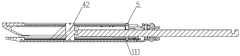
- Fig. 1is a three-dimensional schematic diagram of a stapler in the prior art.
- Figure 2is a three-dimensional schematic diagram of the I-knife in the stapler.
- Fig. 3is a three-dimensional schematic diagram of the unactivated state (open jaws) of the stapler with the stable jaw locking function of the present invention.
- Fig. 4is a partial enlarged view of I in Fig. 3.
- Fig. 5is a three-dimensional schematic diagram of the activated state (the jaws are closed) of the stapler with the stable jaw locking function of the present invention.
- Fig. 6is a partial enlarged view of II in Fig. 5.
- Fig. 7is a cross-sectional view of Fig. 5.
- Fig. 8is an assembly diagram of the first embodiment of the pusher bar, the I-knife and the pressing block in the stapler with stable jaw locking function of the present invention.
- Fig. 9is a three-dimensional schematic diagram of the pressure block of the stapler with the stable jaw locking function of the present invention.
- Fig. 10is a front view of the pressure block in the stapler with the stable jaw locking function of the present invention.
- Fig. 11is a schematic diagram of the second embodiment of the pusher bar, the I-knife and the pressing block in the stapler with stable jaw locking function of the present invention.
- 1- staple cartridge assembly11- staple cartridge rack; 111- blocking step surface; 12- staple cartridge; 13- knife slot; 131- closed section; 132- knife working section; 2- nail anvil; 3- adapter ;4-Pushing knife assembly; 41-Pushing knife bar; 411-First inserting sink groove; 42-I-shaped knife; 421-Second inserting sinking groove; 5-Pressing block; 51-Pushing knife assembly through hole; 52-pressing arm; 521-plugging part; 5211-plugging protrusion; 53-supporting arm; 531-elastic outer arch; 6-pin shaft.
- Figures 3 and 4respectively show a three-dimensional schematic diagram of the unactivated state (open jaws) of the stapler with the stable jaw locking function of the present invention and A partial enlarged view of I;
- Figures 5, 6, and 7respectively show a three-dimensional schematic diagram, a partial enlarged view and a cross-sectional view of the activated state (jaw closed) of the stapler with a stable jaw locking function in the present invention.
- Itis mainly composed of the staple cartridge assembly 1, the nail anvil 2, the adapter 3, the push knife assembly 4 and the pin 6 and other parts.
- the adapter 3, the staple cartridge assembly 1 and the staple anvil 2are hinged into one body by means of a pin shaft 6.
- the pusher assembly 4includes a pusher rod 41 and an I-shaped knife 42.
- the staple cartridge assembly 1includes a staple cartridge rack 11, a staple cartridge 12, and the like.
- the staple cartridge 12 and the staple cartridge frame 11are fixed as a whole, and a knife slot 13 is opened along the length direction thereof for the directional sliding of the I-shaped knife 42 to complete the tissue cutting action.
- the knife pushing assembly 4passes through the adapter 3, and the knife pushing rod 41 is fixed to the I-knife 42.
- the staplerfurther includes a pressing block 5 which is sleeved on the push rod 41 or the I-knife 42.
- the pressing block 5is sleeved on the pusher rod 41, and a pusher assembly through hole 51 is opened on it.
- the pressing block 5includes two pressing arms 52 and two supporting arms 53, which are respectively arranged opposite to each other around the through hole 51 of the push-knife assembly (as shown in FIG. 9).
- An insertion part 521is provided on the pressing arm 52 corresponding to the through hole 51 of the push knife assembly.
- the push rod 41is provided with a first insertion groove that is adapted to the insertion part 521. 411.
- An elastic outer arch 531is provided in the middle of the support arm 53 (as shown in FIG. 10).
- the elastic outer arch 531is squeezed by the knife groove 13 to increase the height of the pressure block 5, causing the insertion portion 521 to separate from the first insertion groove 411 Therefore, the jaw tension generated by squeezing the tissue is mainly borne by the pressure block 5, thereby reducing the force of the I-knife 42 along its own height direction, and making it only subject to the tissue cutting force as much as possible.
- the above-mentioned plug-in portion 521can also be provided on the support arm 53 according to actual conditions, and correspondingly, the first plug-in slot 411 has a corresponding position change on the push rod.
- the above-mentioned knife groove 13includes a closing section 131 and a knife working section 132, which are arranged in sequence along the cutting direction of the I-shaped knife 42.
- the width of the closed section 131is greater than the width of the cutting working section 132, and the two transition smoothly. In this way, when the pressure block 5 is dragged by the push rod 41 from the closed section 131 into the knife working section 132, the elastic outer arch 531 is gradually subjected to the lateral squeezing force to produce inward shrinking deformation, thereby The matching accuracy requirements of the pressing block 5 and the cutting groove 13 are reduced, and the manufacturing cost is reduced.
- the above-mentioned elastic outer arch 531is set in one or more sections, which is set according to actual conditions.
- the width of the pressure block 5should be greater than the width of the I-shaped knife 42, and on the nail magazine rack 11, along the cutting groove 13
- the two side wallsare symmetrically provided with blocking step surfaces 111 outwardly.
- the opening of the two blocking stepped surfaces 111needs to be greater than the width of the I-shaped knife 42 and smaller than the width of the pressing block 5 (as shown in Figs. 4 and 7). In this way, in actual operation, when the stapler is in the activated state, the I-knife 42 and the pressing block 5 move synchronously.
- the pressing block 5is blocked by the blocking step surface 111 and stops moving, and is fixed at a certain position to maintain the opening angle of the jaws. At the same time, the I-knife 42 crosses the blocking step surface 111 to complete the subsequent tissue cutting action.
- the insertion portion 521is preferably an insertion protrusion 5211 , Are arranged on the upper and lower side walls of the push-knife assembly through hole 51, and are arranged symmetrically up and down.
- the first insertion groove 411is arranged on the top and bottom walls of the push-knife lever 41 (as shown in Figures 8, 10). Shown in).
- the cross-sectional shape of the insertion protrusion 5211may preferably be any one of rectangular, trapezoidal, or arc shape, which is selected according to actual application scenarios and manufacturing process conditions in the actual design process.
- the differenceis that the insertion protrusion 5211 can also be transformed to the support arm 53, that is, arranged on the front and rear side walls of the push-knife assembly through hole 51, and are symmetrical to each other. Arrangement.
- the first plug-in slot 411is arranged on the front wall and the rear wall of the push rod 41 (not shown in the figure).
- the pressure block 5when the pressure block 5 is separated from the push rod 41, the pressure block 5 is subjected to the lateral thrust force and increases in size along its height direction, thereby As a result, the plug-in portion 521 is pulled out from the first plug-in slot 411.
- the plug-in portion 521can be pulled out of the first plug-in groove 411 only by the pressing force of the first plug-in groove 411, so that the plug-in portion 521 is connected to the first plug-in groove 411.
- the sink 411loses its locking function.
- the working principle of the above stapleris as follows: in the early stage of operation, the push rod 41 drags the I-knife 42 and the pressing block 5 to move synchronously as a whole until the staple cartridge assembly 1 is in a closed state relative to the staple anvil 2 (ie, the jaws are closed) During this process, the elastic outer arches 531 provided on the left and right sides of the pressure block 5 are gradually compressed inward by the knife groove 13, and the pressing arms 52 provided on the upper and lower sides of the pressure block 5 The distance increases accordingly, and the push rod 41 drags the I-knife 42 to move forward, causing the pressure block 5 to separate from the push rod 41. At the same time, the displacement movement of the pressure block 5 is blocked due to the frictional force.
- the pressing block 5presses and abuts the staple cartridge 12 and the staple anvil 2 respectively by means of its two pressing arms 52, so as to realize the reliable and stable locking of the jaws, and to a large extent share the pressing force.
- the height direction of the block 5is forced to prevent it from breaking and to ensure the safety of the operation.
- FIG. 11is a schematic diagram of the second embodiment of the pusher bar, the I-knife and the pressing block in the stapler with stable jaw locking function according to the present invention.
- the pressing block 5is sleeved on the periphery of the I-shaped knife 42 and fixedly connected.
- the I-shaped knifeis provided with a second insertion groove 421 that is adapted to the insertion protrusion 5211.
Landscapes
- Health & Medical Sciences (AREA)
- Life Sciences & Earth Sciences (AREA)
- Surgery (AREA)
- Heart & Thoracic Surgery (AREA)
- Engineering & Computer Science (AREA)
- Biomedical Technology (AREA)
- Nuclear Medicine, Radiotherapy & Molecular Imaging (AREA)
- Medical Informatics (AREA)
- Molecular Biology (AREA)
- Animal Behavior & Ethology (AREA)
- General Health & Medical Sciences (AREA)
- Public Health (AREA)
- Veterinary Medicine (AREA)
- Portable Nailing Machines And Staplers (AREA)
Abstract
Description
Translated fromChinese本发明涉及吻合器制造技术领域,尤其是一种具有稳定钳口锁合功能的吻合器。The invention relates to the technical field of stapler manufacturing, in particular to an stapler with a stable jaw locking function.
在腹腔镜外科手术和胸腔镜外科手术中,腔镜切割吻合器通常被用于消化道中食管、胃、十二指肠、小肠、结肠、直肠、阑尾、胆、胰和脾等切割吻合手术,也被用于呼吸道中肺和气管等切割吻合手术,还被用于泌尿生殖系统中膀胱和子宫等切割吻合手术,通过其应用可以大大地减少手术创伤口,缩短手术时间以及提高手术质量。In laparoscopic surgery and thoracoscopic surgery, the laparoscopic cutting stapler is usually used for cutting and anastomosing the esophagus, stomach, duodenum, small intestine, colon, rectum, appendix, gallbladder, pancreas, and spleen in the digestive tract. It is also used for incision and anastomosis of lungs and trachea in the respiratory tract, and also for incision and anastomosis of bladder and uterus in the genitourinary system. Through its application, it can greatly reduce the surgical trauma, shorten the operation time and improve the quality of the operation.
一般来说,钉仓与钉仓架固定为一个整体,且沿其长度方向开设有走刀槽。当钳口处于闭合状态时,在推刀杆的推力作用下使得工字刀沿着上述走刀槽到进行定向滑动以实现切割组织的功能。然而,由于钳口内组织物的存在导致其具有开启的趋势。在现有技术中,仅借助于工字刀施加于钉仓以及钉砧上顶靠力来确保钳口始终处于闭合状态(如图1、2中所示),如此,工字刀在进行定向切割的进程中,其始终受到水平方向切割力以及垂直方向顶靠力的双重作用,极易导致其上刀座、下刀座与刀片之间发生断裂现象,增加了手术风险,因而,亟待技术人员解决上述问题。Generally speaking, the staple cartridge and the staple cartridge frame are fixed as a whole, and a knife slot is provided along the length direction. When the jaws are in the closed state, the I-shaped knife is oriented to slide along the above-mentioned knife groove under the pushing force of the knife rod to realize the function of cutting tissue. However, it has a tendency to open due to the presence of tissues in the jaws. In the prior art, only the thrust force applied by the I-shaped knife to the staple cartridge and the nail anvil is used to ensure that the jaws are always in a closed state (as shown in Figures 1 and 2). In this way, the I-shaped knife is oriented During the cutting process, it is always subjected to the dual effects of the horizontal cutting force and the vertical thrust force, which can easily lead to fractures between the upper knife holder, lower knife holder and the blade, which increases the risk of surgery. Therefore, technology is urgently needed. The personnel solve the above problems.
发明内容Summary of the invention
本发明要解决的技术问题是提供一种结构设计简单,降低工字刀受拉断裂风险,确保手术安全性的具有稳定钳口锁合功能的吻合器。The technical problem to be solved by the present invention is to provide a stapler with a simple structure design, which reduces the risk of I-knife breakage under tension and ensures the safety of the operation and has a stable jaw locking function.
为了解决上述技术问题,本发明涉及了一种具有稳定钳口锁合功能的吻合器,包括钉仓组件、钉砧、转接头以及推刀组件。其中,转接头、钉仓组件以及钉砧借助于销轴铰接为一体。推刀组件包括推刀杆和工字刀。钉仓组件包括钉仓架和钉仓。钉仓和钉仓架固定为一体,且沿其长 度方向开设有走刀槽,以供工字刀进行定向滑动。推刀组件穿越转接头,且其推刀杆与工字刀相固定。另外,该具有稳定钳口锁合功能的吻合器还包括压块。该压块套设于推刀组件上,且在其上开设有推刀组件穿越孔。压块包括两压靠臂和两支撑臂,且分别围绕上述推刀组件穿越孔相对而置。在支撑臂或压靠臂上、正对应推刀组件穿越孔设置有插接部,相应地,在推刀杆上设置有与插接部相适配的第一插接沉槽。在所述支撑臂的中部位置设有弹性外拱部。In order to solve the above technical problems, the present invention relates to a stapler with a stable jaw locking function, which includes a staple cartridge assembly, a staple anvil, an adapter, and a push knife assembly. Among them, the adapter, the staple cartridge assembly and the staple anvil are hinged into one body by means of a pin shaft. The push-knife assembly includes a push-knife bar and an I-shaped knife. The staple cartridge assembly includes a staple cartridge rack and a staple cartridge. The staple cartridge and the staple cartridge frame are fixed as a whole, and a knife slot is opened along the length direction for the I-shaped knife to perform directional sliding. The push-knife assembly passes through the adapter, and the push-knife rod is fixed with the I-knife. In addition, the stapler with stable jaw locking function also includes a pressure block. The pressing block is sleeved on the push-knife assembly, and a push-knife assembly through hole is opened on it. The pressing block includes two pressing arms and two supporting arms, and they are respectively arranged opposite to each other around the through hole of the push knife assembly. An inserting part is provided on the support arm or the pressing arm corresponding to the through hole of the push knife assembly, and correspondingly, a first inserting sink groove adapted to the inserting part is provided on the push knife rod. An elastic outer arch is provided at the middle position of the support arm.
作为本发明所公开技术方案的进一步改进,走刀槽包括闭合段和走刀工作段,且沿着工字刀的走刀切割方向依序布置。闭合段的宽度大于走刀工作段的宽度。在压块由闭合段进入到走刀工作段的过程中,弹性外拱部逐渐受到侧向挤压力作用而向内收拢。As a further improvement of the technical solution disclosed in the present invention, the knife groove includes a closed section and a knife working section, and they are arranged in sequence along the cutting direction of the I-shaped knife. The width of the closed section is greater than the width of the working section of the knife. When the pressure block enters the knife working section from the closed section, the elastic outer arch is gradually contracted inward under the action of the lateral squeezing force.
作为本发明所公开技术方案的进一步改进,针对于支撑臂的单一侧壁,弹性外拱部在其上设置为一段或多段。As a further improvement of the technical solution disclosed in the present invention, for the single side wall of the support arm, the elastic outer arch is arranged in one or more sections.
作为本发明所公开技术方案的更进一步改进,压块的宽度大于工字刀的宽度。在钉仓架上、沿着走刀槽的两侧壁向外对称设置有阻挡台阶面。两阻挡台阶面的开档大于工字刀的宽度,而小于压块的宽度,以对支撑臂形成阻挡。As a further improvement of the technical solution disclosed in the present invention, the width of the pressing block is larger than the width of the I-shaped knife. A blocking step surface is symmetrically arranged outwardly along the two side walls of the knife groove on the nail magazine rack. The opening of the two blocking step surfaces is larger than the width of the I-shaped knife and smaller than the width of the pressing block, so as to block the support arm.
作为本发明所公开技术方案的更进一步改进,插接部为设置于推刀组件穿越孔上、下侧壁上、相互对称的插接凸起,相应地,第一插接沉槽布置于推刀杆的顶壁、底壁上。As a further improvement of the technical solution disclosed in the present invention, the inserting portion is a symmetrical inserting protrusion arranged on the upper and lower side walls of the push-knife assembly through hole. Accordingly, the first inserting sink groove is arranged in the pusher. On the top and bottom walls of the arbor.
当然,作为上述技术方案的一种改型,插接部亦可以为设置于推刀组件穿越孔前、后侧壁上、相互对称的插接凸起,相应地,第一插接沉槽布置于推刀杆的前壁、后壁上。Of course, as a modification of the above technical solution, the plug-in portion can also be plug-in protrusions arranged on the front and rear side walls of the push-knife assembly through the hole and are symmetrical to each other. Correspondingly, the first plug-in slot is arranged On the front and back walls of the push rod.
作为本发明所公开技术方案的更进一步改进,插接凸起的截面形状呈矩形、梯形或弧形。As a further improvement of the technical solution disclosed in the present invention, the cross-sectional shape of the plug-in protrusion is rectangular, trapezoidal or arc-shaped.
相较于传统设计结构的吻合器,在发明所公开的技术方案中,额外增设了压块。如此,在实际操作过程中,推刀杆拖动工字刀以及压块进行整体同步移动,直至钉仓组件相对于钉砧处于闭合状态(即钳口闭合), 在此过程中,弹性外拱部逐渐受到所述走刀槽的挤压作用而向内收拢,且对压块的位移形成阻滞,与此同时,压靠臂的间距相应增大,而推刀杆拖动工字刀继续前行,导致压块与推刀杆或工字刀相脱离,此时,压块借助于其两压靠臂分别对钉仓、钉砧进行压紧、顶靠,从而实现钳口的可靠锁合。Compared with the stapler with the traditional design structure, in the technical solution disclosed in the invention, a pressure block is additionally added. In this way, in the actual operation process, the push rod drags the I-knife and the pressing block to move synchronously as a whole until the staple cartridge assembly is in a closed state relative to the staple anvil (that is, the jaws are closed). In this process, the elastic outer arch The part is gradually squeezed by the knife groove to shrink inward, and block the displacement of the pressure block. At the same time, the distance between the pressing arms is correspondingly increased, and the push rod drags the I-shaped knife to continue Moving forward, causing the pressing block to separate from the push rod or I-knife. At this time, the pressing block uses its two pressing arms to respectively press and abut the staple cartridge and the nail anvil, so as to realize the reliable locking of the jaws. Together.
为了更清楚地说明本发明实施例或现有技术中的技术方案,下面将对实施例或现有技术描述中所需要使用的附图作简单地介绍,显而易见地,下面描述中的附图仅仅是本发明的一些实施例,对于本领域普通技术人员来讲,在不付出创造性劳动的前提下,还可以根据这些附图获得其他的附图。In order to explain the embodiments of the present invention or the technical solutions in the prior art more clearly, the following will briefly introduce the drawings that need to be used in the description of the embodiments or the prior art. Obviously, the drawings in the following description are only These are some embodiments of the present invention. For those of ordinary skill in the art, other drawings can be obtained based on these drawings without creative work.
图1是现有技术中吻合器的立体示意图。Fig. 1 is a three-dimensional schematic diagram of a stapler in the prior art.
图2是吻合器中工字刀的立体示意图。Figure 2 is a three-dimensional schematic diagram of the I-knife in the stapler.
图3是本发明中具有稳定钳口锁合功能的吻合器未激发状态(钳口开启)的立体示意图。Fig. 3 is a three-dimensional schematic diagram of the unactivated state (open jaws) of the stapler with the stable jaw locking function of the present invention.
图4是图3的I局部放大图。Fig. 4 is a partial enlarged view of I in Fig. 3.
图5是本发明中具有稳定钳口锁合功能的吻合器激发状态(钳口闭合)的立体示意图。Fig. 5 is a three-dimensional schematic diagram of the activated state (the jaws are closed) of the stapler with the stable jaw locking function of the present invention.
图6是图5的II局部放大图。Fig. 6 is a partial enlarged view of II in Fig. 5.
图7是图5的剖视图。Fig. 7 is a cross-sectional view of Fig. 5.
图8是本发明具有稳定钳口锁合功能的吻合器中推刀杆、工字刀以及压块第一种实施方式的装配示意图。Fig. 8 is an assembly diagram of the first embodiment of the pusher bar, the I-knife and the pressing block in the stapler with stable jaw locking function of the present invention.
图9是本发明具有稳定钳口锁合功能的吻合器中压块的立体示意图。Fig. 9 is a three-dimensional schematic diagram of the pressure block of the stapler with the stable jaw locking function of the present invention.
图10是本发明具有稳定钳口锁合功能的吻合器中压块的主视图。Fig. 10 is a front view of the pressure block in the stapler with the stable jaw locking function of the present invention.
图11是本发明具有稳定钳口锁合功能的吻合器中推刀杆、工字刀以及压块第二种实施方式的装配示意图。Fig. 11 is a schematic diagram of the second embodiment of the pusher bar, the I-knife and the pressing block in the stapler with stable jaw locking function of the present invention.
1-钉仓组件;11-钉仓架;111-阻挡台阶面;12-钉仓;13-走刀槽;131-闭合段;132-走刀工作段;2-钉砧;3-转接头;4-推刀组件;41-推刀杆;411-第一插接沉槽;42-工字刀;421-第二插接沉槽;5-压块;51-推刀组件穿越孔;52-压靠臂;521-插接部;5211-插接凸起;53-支撑臂;531-弹性外拱部;6-销轴。1- staple cartridge assembly; 11- staple cartridge rack; 111- blocking step surface; 12- staple cartridge; 13- knife slot; 131- closed section; 132- knife working section; 2- nail anvil; 3- adapter ;4-Pushing knife assembly; 41-Pushing knife bar; 411-First inserting sink groove; 42-I-shaped knife; 421-Second inserting sinking groove; 5-Pressing block; 51-Pushing knife assembly through hole; 52-pressing arm; 521-plugging part; 5211-plugging protrusion; 53-supporting arm; 531-elastic outer arch; 6-pin shaft.
在本发明的描述中,需要理解的是,术语“前”、“后”、“左”、“右”、“上”、“下”等指示的方位或位置关系为基于附图所示的方位或位置关系,仅是为了便于描述本发明和简化描述,而不是指示或暗示所指的装置或元件必须具有特定的方位、以特定的方位构造和操作,因此不能理解为对本发明的限制。In the description of the present invention, it should be understood that the directions or positional relationships indicated by the terms "front", "rear", "left", "right", "upper", "lower", etc. are based on the drawings shown The orientation or positional relationship is only for the convenience of describing the present invention and simplifying the description, rather than indicating or implying that the pointed device or element must have a specific orientation, be constructed and operated in a specific orientation, and therefore cannot be construed as a limitation of the present invention.
下面结合具体实施例,对本发明的内容做进一步的详细说明,图3、图4分别示出了本发明中具有稳定钳口锁合功能的吻合器未激发状态(钳口开启)的立体示意图及其I局部放大图;图5、图6、图7分别示出了本发明中具有稳定钳口锁合功能的吻合器激发状态(钳口闭合)的立体示意图、II局部放大图以及剖视图,其主要由钉仓组件1、钉砧2、转接头3、推刀组件4以及销轴6等几部分构成。其中,转接头3、钉仓组件1以及钉砧2借助于销轴6铰接为一体。推刀组件4包括推刀杆41以及工字刀42。钉仓组件1包括钉仓架11和钉仓12等。钉仓12和钉仓架11固定为一体,且沿其长度方向开设有走刀槽13,以供上述工字刀42进行定向滑动完成切割组织动作。推刀组件4穿越转接头3,且其推刀杆41与工字刀42相固定。需要着重说明的是,该吻合器还包括有压块5,其套设于推刀杆41或工字刀42上。而在本实施例中,压块5套设于推刀杆41上,且在其上开设有推刀组件穿越孔51。压块5包括两压靠臂52和两支撑臂53,且分别围绕上述推刀组件穿越孔51相对而置(如图9中所示)。在压靠臂52上、正对应于推刀组件穿越孔51设置有插接部521,相应地,在推刀杆41上设置有与上述插接部521相适配 的第一插接沉槽411。在支撑臂53的中部位置设有弹性外拱部531(如图10中所示)。如此,当吻合器处于激发状态时,弹性外拱部531受到走刀槽13的挤压作用而使得压块5的高度尺寸增大,导致插接部521与第一插接沉槽411相脱离,从而挤压组织而产生的钳口张力主要由压块5来承担,进而减小了工字刀42沿其自身高度方向上的受力,尽可能地使其仅受到组织切割力的作用。The following describes the content of the present invention in further detail with reference to specific embodiments. Figures 3 and 4 respectively show a three-dimensional schematic diagram of the unactivated state (open jaws) of the stapler with the stable jaw locking function of the present invention and A partial enlarged view of I; Figures 5, 6, and 7 respectively show a three-dimensional schematic diagram, a partial enlarged view and a cross-sectional view of the activated state (jaw closed) of the stapler with a stable jaw locking function in the present invention. It is mainly composed of the staple cartridge assembly 1, the nail anvil 2, the adapter 3, the push knife assembly 4 and the
当然,上述插接部521亦可以根据实际情况设置于支撑臂53上,相应地,第一插接沉槽411在推刀杆上作相应位置改变。Of course, the above-mentioned plug-in portion 521 can also be provided on the
作为上述具有稳定钳口锁合功能吻合器的进一步优化,上述走刀槽13包括闭合段131和走刀工作段132,且沿着工字刀42的走刀切割方向依序布置。闭合段131的宽度大于走刀工作段132的宽度,且两者光滑平缓过渡。如此,压块5在推刀杆41的拖动下由闭合段131进入到走刀工作段132的过程中,弹性外拱部531逐渐受到侧向挤压力作用而产生向内收拢变形,从而降低压块5与走刀槽13的配合精度要求,降低制造成本。As a further optimization of the above-mentioned stapler with stable jaw locking function, the above-mentioned knife groove 13 includes a
在此需要说明一点,针对于支撑臂53的单一侧壁(前侧壁或后侧壁),上述弹性外拱部531在其上设置为一段或多段,根据实际情况进行设定。It should be noted here that for a single side wall (front side wall or rear side wall) of the
为了进一步确保插接部521与第一插接沉槽411脱离的可靠性,上述压块5的宽度应大于工字刀42的宽度,且在钉仓架11上、沿着走刀槽13的两侧壁向外对称设置有阻挡台阶面111。两阻挡台阶面111的开档需大于工字刀42的自身宽度,而小于压块5的宽度(如图4、7中所示)。如此,在实际操作过程中,当吻合器处于激发状态时,工字刀42和压块5进行同步移动。在工字刀42正式进行切割工作前,压块5受到阻挡台阶面111的阻挡作用而停止前行,固定于某一位置保持不变以保持钳口的开口角度,与此同时,工字刀42越过阻挡台阶面111以完成后续组织切割动作。In order to further ensure the reliability of the detachment of the inserting portion 521 from the first inserting sink groove 411, the width of the
图8示出了本发明具有稳定钳口锁合功能的吻合器中推刀杆、工字 刀以及压块第一种实施方式的装配示意图,可知,插接部521优选为插接凸起5211,设置于推刀组件穿越孔51上、下侧壁上,且上下对称布置,相应地,第一插接沉槽411布置于推刀杆41的顶壁、底壁上(如图8、10中所示)。作为更进一步的优化,插接凸起5211的截面形状可以优选为矩形、梯形或弧形中的任一种,在实际设计过程中,根据实际应用场景以及制造工艺条件进行选定。8 shows the assembly diagram of the first embodiment of the push rod, the I-knife, and the pressing block in the stapler with stable jaw locking function of the present invention. It can be seen that the insertion portion 521 is preferably an
当然,作为上述技术方案的一种改型,其区别点在于:插接凸起5211亦可变换至支撑臂53上,即设置于推刀组件穿越孔51前、后侧壁上,且相互对称布置,相应地,第一插接沉槽411布置于推刀杆41的前壁、后壁上(图中未示出)。Of course, as a modification of the above technical solution, the difference is that the
在此需要说明的是,上述二种技术方案中,当压块5与推刀杆41相脱离的过程中,压块5受到侧向顶靠力的作用而沿其高度方向尺寸增大,从而使得插接部521由第一插接沉槽411内脱出。另外,在某些特殊情况下,插接部521仅受到第一插接沉槽411挤压力的作用亦可由第一插接沉槽411内脱出,从而使得插接部521与第一插接沉槽411失去锁合作用。It should be noted here that, in the above two technical solutions, when the
上述吻合器的工作原理如下:在操作前期,推刀杆41拖动工字刀42以及压块5进行整体同步移动,直至钉仓组件1相对于钉砧2处于闭合状态(即钳口闭合),在此过程中,设置于压块5左、右侧的弹性外拱部531逐渐受到走刀槽13的挤压作用而向内收拢,设置于压块5上、下侧的压靠臂52间距相应增大,而推刀杆41拖动工字刀42继续前行,导致压块5与推刀杆41相脱离,与此同时压块5由于受到摩擦力的作用而位移运动受到阻滞,此时,压块5借助于其两压靠臂52分别对钉仓12、钉砧2进行压紧、顶靠,从而实现钳口的可靠、稳定锁合,在很大程度上分担了压块5的高度方向受力,防止其发生断裂现象,确保手术的安全性。The working principle of the above stapler is as follows: in the early stage of operation, the push rod 41 drags the I-
图11是本发明具有稳定钳口锁合功能的吻合器中推刀杆、工字刀以及压块第二种实施方式的装配示意图,其相较于上述第一种实施方式的 区别点在于:压块5套设于工字刀42的外围,且固定连接,相应地,在工字刀上开设有与插接凸起5211相适配的第二插接沉槽421。11 is a schematic diagram of the second embodiment of the pusher bar, the I-knife and the pressing block in the stapler with stable jaw locking function according to the present invention. Compared with the above-mentioned first embodiment, the difference lies in: The
对所公开的实施例的上述说明,使本领域专业技术人员能够实现或使用本发明。对这些实施例的多种修改对本领域的专业技术人员来说将是显而易见的,本文中所定义的一般原理可以在不脱离本发明的精神或范围的情况下,在其它实施例中实现。因此,本发明将不会被限制于本文所示的这些实施例,而是要符合与本文所公开的原理和新颖特点相一致的最宽的范围。The foregoing description of the disclosed embodiments enables those skilled in the art to implement or use the present invention. Various modifications to these embodiments will be obvious to those skilled in the art, and the general principles defined herein can be implemented in other embodiments without departing from the spirit or scope of the present invention. Therefore, the present invention will not be limited to the embodiments shown in this document, but should conform to the widest scope consistent with the principles and novel features disclosed in this document.
Claims (7)
Translated fromChineseApplications Claiming Priority (2)
| Application Number | Priority Date | Filing Date | Title |
|---|---|---|---|
| CN201910858785.9 | 2019-09-11 | ||
| CN201910858785.9ACN110420043B (en) | 2019-09-11 | 2019-09-11 | Anastomat with stable jaw locking function |
Publications (1)
| Publication Number | Publication Date |
|---|---|
| WO2021047366A1true WO2021047366A1 (en) | 2021-03-18 |
Family
ID=68418986
Family Applications (1)
| Application Number | Title | Priority Date | Filing Date |
|---|---|---|---|
| PCT/CN2020/110246CeasedWO2021047366A1 (en) | 2019-09-11 | 2020-08-20 | Stapler having stable jaw locking function |
Country Status (2)
| Country | Link |
|---|---|
| CN (1) | CN110420043B (en) |
| WO (1) | WO2021047366A1 (en) |
Families Citing this family (3)
| Publication number | Priority date | Publication date | Assignee | Title |
|---|---|---|---|---|
| CN110420043B (en)* | 2019-09-11 | 2024-11-01 | 康奇舒宁(苏州)医疗科技有限公司 | Anastomat with stable jaw locking function |
| MX2023000379A (en)* | 2020-07-06 | 2023-02-13 | Prodeon Medical Corp | Self-actuating grasping device. |
| WO2022110249A1 (en)* | 2020-11-30 | 2022-06-02 | 苏州英途康医疗科技有限公司 | Stapler |
Citations (6)
| Publication number | Priority date | Publication date | Assignee | Title |
|---|---|---|---|---|
| CN203634230U (en)* | 2013-12-31 | 2014-06-11 | 苏州天臣国际医疗科技有限公司 | Linear suture cutting device |
| CN104473671A (en)* | 2014-12-30 | 2015-04-01 | 苏州天臣国际医疗科技有限公司 | Medical anastomat |
| CN204364052U (en)* | 2014-12-31 | 2015-06-03 | 苏州天臣国际医疗科技有限公司 | A kind of nail-head component and there is the chamber mirror Endo-GIA of this nail-head component |
| US20150374368A1 (en)* | 2005-08-31 | 2015-12-31 | Ethicon Endo-Surgery, Inc. | Fastener cartridge assembly comprising a fixed anvil |
| CN110420043A (en)* | 2019-09-11 | 2019-11-08 | 康奇舒宁(苏州)医疗科技有限公司 | It is a kind of with the stapler for stablizing jaw locking function |
| CN210811271U (en)* | 2019-09-11 | 2020-06-23 | 康奇舒宁(苏州)医疗科技有限公司 | A stapler with stable jaw locking function |
Family Cites Families (2)
| Publication number | Priority date | Publication date | Assignee | Title |
|---|---|---|---|---|
| US5507773A (en)* | 1994-02-18 | 1996-04-16 | Ethicon Endo-Surgery | Cable-actuated jaw assembly for surgical instruments |
| CN211633432U (en)* | 2019-09-11 | 2020-10-09 | 舒拓 | Briquetting takes off and closes mechanism suitable for anastomat |
- 2019
- 2019-09-11CNCN201910858785.9Apatent/CN110420043B/enactiveActive
- 2020
- 2020-08-20WOPCT/CN2020/110246patent/WO2021047366A1/ennot_activeCeased
Patent Citations (6)
| Publication number | Priority date | Publication date | Assignee | Title |
|---|---|---|---|---|
| US20150374368A1 (en)* | 2005-08-31 | 2015-12-31 | Ethicon Endo-Surgery, Inc. | Fastener cartridge assembly comprising a fixed anvil |
| CN203634230U (en)* | 2013-12-31 | 2014-06-11 | 苏州天臣国际医疗科技有限公司 | Linear suture cutting device |
| CN104473671A (en)* | 2014-12-30 | 2015-04-01 | 苏州天臣国际医疗科技有限公司 | Medical anastomat |
| CN204364052U (en)* | 2014-12-31 | 2015-06-03 | 苏州天臣国际医疗科技有限公司 | A kind of nail-head component and there is the chamber mirror Endo-GIA of this nail-head component |
| CN110420043A (en)* | 2019-09-11 | 2019-11-08 | 康奇舒宁(苏州)医疗科技有限公司 | It is a kind of with the stapler for stablizing jaw locking function |
| CN210811271U (en)* | 2019-09-11 | 2020-06-23 | 康奇舒宁(苏州)医疗科技有限公司 | A stapler with stable jaw locking function |
Also Published As
| Publication number | Publication date |
|---|---|
| CN110420043A (en) | 2019-11-08 |
| CN110420043B (en) | 2024-11-01 |
Similar Documents
| Publication | Publication Date | Title |
|---|---|---|
| WO2021047366A1 (en) | Stapler having stable jaw locking function | |
| US3079606A (en) | Instrument for placing lateral gastrointestinal anastomoses | |
| US9855042B1 (en) | End effector of surgical linear stapler | |
| ES2385698T3 (en) | Endoscopic applicator of surgical bras in a single movement | |
| KR101820517B1 (en) | Structure of effector of surgical instrument | |
| CN204351883U (en) | A kind of nail kit assembly for anastomat, chamber endoscopic stapler device, line cutting stitching instrument, surgical operating instrument | |
| RU2717204C1 (en) | Device for tissue closure and medical instrument | |
| JP2018505729A (en) | Surgical clip applier with multiple clip supply mechanism | |
| BR112012008264B1 (en) | SURGICAL CLIP APPLICATOR AND METHOD FOR ADVANCING A CLIP INTO OPPOSITE JAWS OF A CLIP APPLICATOR | |
| CN104473671B (en) | Medical stapler | |
| CN103228223A (en) | Medical device with detachable pivotable jaws | |
| EP3725235A1 (en) | Staple cartridge assembly and medical stapler using same | |
| CN109953786A (en) | Nail cartridge assembly and medical stapler using the same | |
| CN204364052U (en) | A kind of nail-head component and there is the chamber mirror Endo-GIA of this nail-head component | |
| WO2024104343A1 (en) | Anvil and surgical instrument | |
| WO2024104196A1 (en) | Staple cartridge assembly for surgical instrument and surgical instrument | |
| CN211633432U (en) | Briquetting takes off and closes mechanism suitable for anastomat | |
| CN104434245A (en) | End effector, surgical operating instrument and purse-string forceps | |
| CN210811271U (en) | A stapler with stable jaw locking function | |
| WO2019128721A1 (en) | Handle assembly and anastomat comprising same | |
| CN111789646A (en) | Loading unit with improved coupling assembly | |
| CN203815519U (en) | Staple cartridge assembly and stapler provided with same | |
| CN104107077B (en) | Stapler and the nail bin groupware for this stapler | |
| CN216221543U (en) | Anastomat assembly and anastomat | |
| US20250072892A1 (en) | End effector for surgical stapling device |
Legal Events
| Date | Code | Title | Description |
|---|---|---|---|
| 121 | Ep: the epo has been informed by wipo that ep was designated in this application | Ref document number:20862900 Country of ref document:EP Kind code of ref document:A1 | |
| NENP | Non-entry into the national phase | Ref country code:DE | |
| 122 | Ep: pct application non-entry in european phase | Ref document number:20862900 Country of ref document:EP Kind code of ref document:A1 |