WO2021045546A2 - Device for guiding position of robot, method therefor, and system comprising same - Google Patents
Device for guiding position of robot, method therefor, and system comprising sameDownload PDFInfo
- Publication number
- WO2021045546A2 WO2021045546A2PCT/KR2020/011895KR2020011895WWO2021045546A2WO 2021045546 A2WO2021045546 A2WO 2021045546A2KR 2020011895 WKR2020011895 WKR 2020011895WWO 2021045546 A2WO2021045546 A2WO 2021045546A2
- Authority
- WO
- WIPO (PCT)
- Prior art keywords
- robot
- posture
- surgical
- area
- marker
- Prior art date
- Legal status (The legal status is an assumption and is not a legal conclusion. Google has not performed a legal analysis and makes no representation as to the accuracy of the status listed.)
- Ceased
Links
Images


Classifications
- A—HUMAN NECESSITIES
- A61—MEDICAL OR VETERINARY SCIENCE; HYGIENE
- A61B—DIAGNOSIS; SURGERY; IDENTIFICATION
- A61B34/00—Computer-aided surgery; Manipulators or robots specially adapted for use in surgery
- A61B34/30—Surgical robots
- A—HUMAN NECESSITIES
- A61—MEDICAL OR VETERINARY SCIENCE; HYGIENE
- A61B—DIAGNOSIS; SURGERY; IDENTIFICATION
- A61B34/00—Computer-aided surgery; Manipulators or robots specially adapted for use in surgery
- A61B34/10—Computer-aided planning, simulation or modelling of surgical operations
- A—HUMAN NECESSITIES
- A61—MEDICAL OR VETERINARY SCIENCE; HYGIENE
- A61B—DIAGNOSIS; SURGERY; IDENTIFICATION
- A61B34/00—Computer-aided surgery; Manipulators or robots specially adapted for use in surgery
- A61B34/20—Surgical navigation systems; Devices for tracking or guiding surgical instruments, e.g. for frameless stereotaxis
- A—HUMAN NECESSITIES
- A61—MEDICAL OR VETERINARY SCIENCE; HYGIENE
- A61B—DIAGNOSIS; SURGERY; IDENTIFICATION
- A61B34/00—Computer-aided surgery; Manipulators or robots specially adapted for use in surgery
- A61B34/25—User interfaces for surgical systems
- A—HUMAN NECESSITIES
- A61—MEDICAL OR VETERINARY SCIENCE; HYGIENE
- A61B—DIAGNOSIS; SURGERY; IDENTIFICATION
- A61B90/00—Instruments, implements or accessories specially adapted for surgery or diagnosis and not covered by any of the groups A61B1/00 - A61B50/00, e.g. for luxation treatment or for protecting wound edges
- A61B90/36—Image-producing devices or illumination devices not otherwise provided for
- A61B90/37—Surgical systems with images on a monitor during operation
- A—HUMAN NECESSITIES
- A61—MEDICAL OR VETERINARY SCIENCE; HYGIENE
- A61B—DIAGNOSIS; SURGERY; IDENTIFICATION
- A61B90/00—Instruments, implements or accessories specially adapted for surgery or diagnosis and not covered by any of the groups A61B1/00 - A61B50/00, e.g. for luxation treatment or for protecting wound edges
- A61B90/39—Markers, e.g. radio-opaque or breast lesions markers
- A—HUMAN NECESSITIES
- A61—MEDICAL OR VETERINARY SCIENCE; HYGIENE
- A61F—FILTERS IMPLANTABLE INTO BLOOD VESSELS; PROSTHESES; DEVICES PROVIDING PATENCY TO, OR PREVENTING COLLAPSING OF, TUBULAR STRUCTURES OF THE BODY, e.g. STENTS; ORTHOPAEDIC, NURSING OR CONTRACEPTIVE DEVICES; FOMENTATION; TREATMENT OR PROTECTION OF EYES OR EARS; BANDAGES, DRESSINGS OR ABSORBENT PADS; FIRST-AID KITS
- A61F2/00—Filters implantable into blood vessels; Prostheses, i.e. artificial substitutes or replacements for parts of the body; Appliances for connecting them with the body; Devices providing patency to, or preventing collapsing of, tubular structures of the body, e.g. stents
- A61F2/02—Prostheses implantable into the body
- A61F2/30—Joints
- A61F2/46—Special tools for implanting artificial joints
- A61F2/4603—Special tools for implanting artificial joints for insertion or extraction of endoprosthetic joints or of accessories thereof
- A61F2/461—Special tools for implanting artificial joints for insertion or extraction of endoprosthetic joints or of accessories thereof of knees
- B—PERFORMING OPERATIONS; TRANSPORTING
- B25—HAND TOOLS; PORTABLE POWER-DRIVEN TOOLS; MANIPULATORS
- B25J—MANIPULATORS; CHAMBERS PROVIDED WITH MANIPULATION DEVICES
- B25J9/00—Programme-controlled manipulators
- B25J9/16—Programme controls
- B25J9/1656—Programme controls characterised by programming, planning systems for manipulators
- B25J9/1664—Programme controls characterised by programming, planning systems for manipulators characterised by motion, path, trajectory planning
- B—PERFORMING OPERATIONS; TRANSPORTING
- B25—HAND TOOLS; PORTABLE POWER-DRIVEN TOOLS; MANIPULATORS
- B25J—MANIPULATORS; CHAMBERS PROVIDED WITH MANIPULATION DEVICES
- B25J9/00—Programme-controlled manipulators
- B25J9/16—Programme controls
- B25J9/1679—Programme controls characterised by the tasks executed
- B25J9/1684—Tracking a line or surface by means of sensors
- B—PERFORMING OPERATIONS; TRANSPORTING
- B25—HAND TOOLS; PORTABLE POWER-DRIVEN TOOLS; MANIPULATORS
- B25J—MANIPULATORS; CHAMBERS PROVIDED WITH MANIPULATION DEVICES
- B25J9/00—Programme-controlled manipulators
- B25J9/16—Programme controls
- B25J9/1679—Programme controls characterised by the tasks executed
- B25J9/1689—Teleoperation
- B—PERFORMING OPERATIONS; TRANSPORTING
- B25—HAND TOOLS; PORTABLE POWER-DRIVEN TOOLS; MANIPULATORS
- B25J—MANIPULATORS; CHAMBERS PROVIDED WITH MANIPULATION DEVICES
- B25J9/00—Programme-controlled manipulators
- B25J9/16—Programme controls
- B25J9/1694—Programme controls characterised by use of sensors other than normal servo-feedback from position, speed or acceleration sensors, perception control, multi-sensor controlled systems, sensor fusion
- B25J9/1697—Vision controlled systems
- A—HUMAN NECESSITIES
- A61—MEDICAL OR VETERINARY SCIENCE; HYGIENE
- A61B—DIAGNOSIS; SURGERY; IDENTIFICATION
- A61B34/00—Computer-aided surgery; Manipulators or robots specially adapted for use in surgery
- A61B34/10—Computer-aided planning, simulation or modelling of surgical operations
- A61B2034/101—Computer-aided simulation of surgical operations
- A61B2034/105—Modelling of the patient, e.g. for ligaments or bones
- A—HUMAN NECESSITIES
- A61—MEDICAL OR VETERINARY SCIENCE; HYGIENE
- A61B—DIAGNOSIS; SURGERY; IDENTIFICATION
- A61B34/00—Computer-aided surgery; Manipulators or robots specially adapted for use in surgery
- A61B34/10—Computer-aided planning, simulation or modelling of surgical operations
- A61B2034/107—Visualisation of planned trajectories or target regions
- A—HUMAN NECESSITIES
- A61—MEDICAL OR VETERINARY SCIENCE; HYGIENE
- A61B—DIAGNOSIS; SURGERY; IDENTIFICATION
- A61B34/00—Computer-aided surgery; Manipulators or robots specially adapted for use in surgery
- A61B34/20—Surgical navigation systems; Devices for tracking or guiding surgical instruments, e.g. for frameless stereotaxis
- A61B2034/2046—Tracking techniques
- A61B2034/2055—Optical tracking systems
- A—HUMAN NECESSITIES
- A61—MEDICAL OR VETERINARY SCIENCE; HYGIENE
- A61B—DIAGNOSIS; SURGERY; IDENTIFICATION
- A61B34/00—Computer-aided surgery; Manipulators or robots specially adapted for use in surgery
- A61B34/20—Surgical navigation systems; Devices for tracking or guiding surgical instruments, e.g. for frameless stereotaxis
- A61B2034/2068—Surgical navigation systems; Devices for tracking or guiding surgical instruments, e.g. for frameless stereotaxis using pointers, e.g. pointers having reference marks for determining coordinates of body points
- A—HUMAN NECESSITIES
- A61—MEDICAL OR VETERINARY SCIENCE; HYGIENE
- A61B—DIAGNOSIS; SURGERY; IDENTIFICATION
- A61B34/00—Computer-aided surgery; Manipulators or robots specially adapted for use in surgery
- A61B34/25—User interfaces for surgical systems
- A61B2034/254—User interfaces for surgical systems being adapted depending on the stage of the surgical procedure
- A—HUMAN NECESSITIES
- A61—MEDICAL OR VETERINARY SCIENCE; HYGIENE
- A61B—DIAGNOSIS; SURGERY; IDENTIFICATION
- A61B90/00—Instruments, implements or accessories specially adapted for surgery or diagnosis and not covered by any of the groups A61B1/00 - A61B50/00, e.g. for luxation treatment or for protecting wound edges
- A61B90/36—Image-producing devices or illumination devices not otherwise provided for
- A61B2090/364—Correlation of different images or relation of image positions in respect to the body
- A—HUMAN NECESSITIES
- A61—MEDICAL OR VETERINARY SCIENCE; HYGIENE
- A61B—DIAGNOSIS; SURGERY; IDENTIFICATION
- A61B90/00—Instruments, implements or accessories specially adapted for surgery or diagnosis and not covered by any of the groups A61B1/00 - A61B50/00, e.g. for luxation treatment or for protecting wound edges
- A61B90/39—Markers, e.g. radio-opaque or breast lesions markers
- A61B2090/3904—Markers, e.g. radio-opaque or breast lesions markers specially adapted for marking specified tissue
- A61B2090/3916—Bone tissue
- A—HUMAN NECESSITIES
- A61—MEDICAL OR VETERINARY SCIENCE; HYGIENE
- A61F—FILTERS IMPLANTABLE INTO BLOOD VESSELS; PROSTHESES; DEVICES PROVIDING PATENCY TO, OR PREVENTING COLLAPSING OF, TUBULAR STRUCTURES OF THE BODY, e.g. STENTS; ORTHOPAEDIC, NURSING OR CONTRACEPTIVE DEVICES; FOMENTATION; TREATMENT OR PROTECTION OF EYES OR EARS; BANDAGES, DRESSINGS OR ABSORBENT PADS; FIRST-AID KITS
- A61F2/00—Filters implantable into blood vessels; Prostheses, i.e. artificial substitutes or replacements for parts of the body; Appliances for connecting them with the body; Devices providing patency to, or preventing collapsing of, tubular structures of the body, e.g. stents
- A61F2/02—Prostheses implantable into the body
- A61F2/30—Joints
- A61F2/46—Special tools for implanting artificial joints
- A61F2002/4632—Special tools for implanting artificial joints using computer-controlled surgery, e.g. robotic surgery
Definitions
- the present inventionrelates to a position guide device of a robot, a method thereof, and a system including the same, and more particularly, by deriving an operable area according to the position and posture of the object and the robot to be operated, the position and posture of the object to be operated and the robot are determined. It relates to a device, method and system that can be guided.
- the surgical pathis determined in advance, an optical marker is mounted on the object to be operated, and the position and posture of the optical marker are tracked with an optical sensor, The operation is performed by monitoring the position of the robot.
- the surgical pathmay be in an area that cannot be reached by the end effector of the arm of the robot, or an error may occur in the robot kinematics during movement according to the movement path.
- the operation area of the robotcan be known only when the starting point is determined according to the position setting of the robot, the operation may be stopped because the robot cannot reach the required operation position during the operation.
- the present inventionhas been proposed to solve the above problems, and an object of the present invention is to provide a system and method capable of checking whether a robot is in an operable position and posture along a surgical path before surgery.
- an object of the present inventionis to provide a system and method capable of guiding a position and posture so that a robot can be positioned in an operable area.
- an object of the present inventionis to provide a system and method capable of guiding a position and posture so that an object for surgery is located in a position area and a posture area in which a robot can operate. .
- the position guide device of the robot for achieving the above objectis, by matching an image including an object marker attached to an object to be operated with an image to be operated on the object to be operated before surgery, and the object marker attached to the object to be operated and the operation
- a surgical object matching unitfor deriving a correlation with respect to the position and posture between the objects; Based on an image including a robot marker attached to a surgical robot, a correlation regarding a position and a posture between the robot marker and the surgical robot is derived, and a correlation regarding a position and posture between the robot marker and a preset operable area A robot matching unit to derive; And a surgery area checking unit that derives a correlation with respect to the position and posture between the subject to be operated and the operable area based on the position and posture information of the object marker and the robot marker.
- the method of guiding the position of the robot to achieve the above objectis to match the image including the object marker attached to the object to be operated with the image to be operated on the object to be operated before surgery, and the object marker attached to the object to be operated and the object to be operated. Deriving a correlation regarding the position and posture of the liver; Based on an image including a marker attached to a surgical robot, a correlation with respect to the position and posture between the robot marker and the surgical robot is derived, and a correlation with respect to the position and posture between the robot marker and a preset operable area is determined.
- DerivingDeriving a correlation with respect to the position and posture between the object to be operated and the operable area based on the position and posture information of the object marker and the robot marker; And generating guide information about a correlation between a position and a posture between the object to be operated and the operable area in a graphic form and displaying the image as an image.
- a robot position guide system for achieving the above objectincludes: a robot marker attached to a surgical robot and a tracker for tracking the position and posture of the object marker attached to the surgical object; A memory unit for storing an image to be operated on the object to be operated acquired before surgery; A surgical object matching unit for deriving a correlation with respect to a position and a posture between the object marker attached to the object and the object based on the image to be operated; A robot matching unit for deriving a correlation with respect to the position and posture between the robot marker and the surgical robot, and deriving a correlation with respect to the position and posture between the robot marker and a preset operable area; An operation area checking unit for deriving a correlation with respect to the position and posture between the subject and the operable area based on the position and posture information of the object marker and the robot marker acquired by the tracker; A GUI generator that graphically generates guide information on a correlation between the position and posture between the object and the operable area; And a display unit that displays the guide information as an image.
- the present inventionit is possible to know whether the position and posture of the object to be operated belongs to the operable area of the surgical robot. In addition, according to the present invention, by guiding the robot to move to an operable position and posture, it is possible to minimize the risk of stopping the operation. In addition, according to the present invention, the robot can smoothly proceed with the operation by notifying the posture of the object to be operated on in an operable posture.
- FIG. 1schematically shows a position guide system of a robot according to an embodiment of the present invention.
- FIG. 2is a control block diagram of a position guide device according to an embodiment of the present invention.
- FIG. 3is a view for explaining the operation of the operation object matching unit according to an embodiment of the present invention.
- FIG. 4is a view for explaining the operation of the robot matching unit according to an embodiment of the present invention.
- FIG. 5is a view for explaining the operation of the operation area check unit according to an embodiment of the present invention.
- FIG. 6illustrates an example of guide information generated by a GUI generator according to an embodiment of the present invention.
- FIG. 7is a flowchart illustrating a method of guiding a position by a robot position guiding device according to an exemplary embodiment of the present invention.
- FIGS. 1 to 5a position guide system and apparatus for a robot according to an embodiment of the present invention will be described with reference to FIGS. 1 to 5.
- a robot position guide systemaccording to an embodiment of the present invention includes bone markers 10 and 20 attached to the surgical objects 1 and 2, the surgical robot 30, and a tracker ( 40), and a position guide device 100.
- the object to be operated (1, 2)refers to an object of surgery, and in the embodiment of the present invention, the object to be operated is a knee joint of the femur (1) and the tibia (2), and the object marker 10, 20) will be described as an example that is attached to each of the femur (1) and tibia (2).
- the surgical robot 30is for joint surgery and includes a robot base and an arm, and a cutting tool may be positioned on an end effector of the arm.
- a robot marker 31is attached to the base of the surgical robot 30.
- Optical markersmay be used for the object markers 10 and 20 and the robot marker 31, and three or four bar types in different directions based on the center point are formed, and at the ends of the bars, respectively.
- a highly reflective ball markermay be formed.
- the tracker 40is for tracking the position and posture of the robot marker 31 attached to the surgical robot 30 and the object markers 10 and 20 attached to the surgical objects 1 and 2, and are coordinated in three-dimensional space.
- the position and posture of the image markeris sensed and transmitted to the position guide device 100 to be described later.
- the tracker 40will be described as an example that is implemented as an optical tracking system (OTS).
- OTSoptical tracking system
- the position guide device 100receives a signal input from the tracker 40 to perform the registration of the surgical objects 1 and 2 and the registration of the surgical robot 30, and the surgical objects 1 and 2 and the surgical robot ( 30) is to guide the position of the surgical robot 30 by deriving a correlation with respect to the position/posture between the operable areas, and as shown in FIG. 1, it may be implemented including a computer or a microprocessor and a display. have.
- the position guide device 100is shown to be separated from the surgical robot 30 and implemented as a separate device.
- the computer or microprocessor of the position guide device 100is within the surgical robot 30. It is installed, and the display of the position guide device may be connected to the tracker 40 and installed together. In this case, the position guide device 100 in the surgical robot 30 is connected to the tracker 40 to receive the position/position information of the markers, process it, and provide it to the display.
- the position guide device 100includes a signal receiving unit 110, a user input unit 120, a display unit 130, a memory unit 140, and a control unit 150. Includes.
- the signal receiving unit 110is for receiving a signal from the outside, for example, an HDMI (High Definition Multimedia Interface) connector 11, a D-sub connector, or an Internet network for connection with an external device. It may include a communication module for connecting to a wired/wireless communication network including. The signal receiving unit 110 may include a wired/wireless communication module for interworking with the tracker 40 and the surgical robot 30.
- HDMIHigh Definition Multimedia Interface
- D-sub connectorDigital Multimedia Interface
- Internet networkfor connection with an external device.
- the signal receiving unit 110may include a communication module for connecting to a wired/wireless communication network including.
- the signal receiving unit 110may include a wired/wireless communication module for interworking with the tracker 40 and the surgical robot 30.
- the user input unit 120is for receiving a command from the user and transmitting it to the control unit 150 to be described later, and may include at least one of various user input means such as a keyboard, a mouse, or a button.
- the display unit 130is for displaying an image on a screen, such as a liquid crystal display (LCD) panel, a light emitting diode (LED) panel, an organic light emitting diode (OLED) panel, etc. It can be implemented as
- the memory unit 140may store various OSs, middleware, platforms, and various applications of the location guide device 100, and store program codes, signal-processed video signals, audio signals, and data.
- the memory unit 140stores an image to be operated on, for example, a CT image of a patient, which is acquired before the operation.
- the memory unit 140may be implemented as a read only memory (ROM), an erasable programmable read-only memory (EPROM), a random access memory (RAM), or the like.
- the control unit 150is in charge of overall control of the location guide device 100 by a user command input through the user input unit 120 or an internal program.
- the control unit 150may be implemented by including a computer program code for signal processing and control and a microprocessor executing the computer program.
- the control unit 150performs image registration and location tracking using the location/position information received from the tracker 40 through the signal receiving unit 110, and the relationship between the surgical object and the operable area of the surgical robot 30 By deriving, guide information for guiding the position and posture of the surgical robot 30 is provided to the user.
- control unit 150includes an operation object matching unit 151, a robot matching unit 153, an operation area checking unit 155, and a GUI generating unit 157.
- the surgical object matching unit 151derives a correlation with respect to the position/position between the object markers 10 and 20 attached to the surgical objects 1 and 2 and the surgical objects 1 and 2 through image registration. After attaching the object markers 10 and 20 to the object to be operated on, the position and posture of the object to be operated and the object markers 10 and 20 are recognized using a probe. The surgical object matching unit 151 receives an optical image about the position and posture indicated by the probe through the tracker 40, and performs matching with 3D data of the patient, for example, a CT image previously stored in the memory unit 140. It is possible to derive a correlation with respect to the position/position between the object markers 10 and 20 and the surgical objects 1 and 2.
- the operation object matching unit 151may be implemented as a software algorithm for image registration.
- the object to be operatedis a knee joint of the femur 1 and the tibia 2, and the object markers 10 and 20 are attached to the femur 1 and the tibia 2.
- FICFemur Implant Coordinate
- FMCFemur Marker Coordinate
- the surgical object registration unit 151obtains the position and posture information of the femur 1 and the femur marker 10 while scraping the probe by contacting a plurality of points of the femur 1 and matching it with a CT image to obtain the femur marker. (10) and the correlation with respect to the position / posture of the femoral implant origin (FIO), for example, the coordinates of the position / posture between the coordinate system of the femur marker 10 and the coordinate system (FIC) based on the femoral implant origin (FIO)
- the transformation matrix ( F T FI ) as a transformation relationshipcan be derived.
- the controller 150converts the position and posture information of the femur marker 10 into a transformation matrix derived from the operation object matching unit 151. By multiplying by ( F T FI ), the position and posture of the femur (1), including the implant origin of the femur (1), can be derived.
- Tibia Implant Coordinaterefers to a coordinate system based on the position and posture of the Tibia Implant Origin (TIO) of the tibia 2
- Tibia Marker Coordinaterefers to the tibia marker 20. It refers to a coordinate system based on position and posture.
- the implant origin of the tibia 2means the origin of the surgical path, that is, the cutting path.
- the surgical object registration unit 151obtains the position and posture information of the tibia 2 and the tibia marker 20 while scraping the probe by contacting a plurality of points of the tibia 2, and matches this with the CT image to obtain the tibia marker. (20) and the correlation of the position / posture between the tibia implant origin (Tibia Implant Origin, TIO), for example, the position / between the coordinate system of the tibia marker 20 and the coordinate system based on the tibia implant origin (Tibia Implant Origin, TIO)
- T T TIwhich is a coordinate transformation relationship for the posture, is derived.
- the control unit 150converts the position and posture information of the tibia marker 20 derived from the operation object matching unit 151.
- the matrix ( T T TI )By multiplying the matrix ( T T TI ), the position and posture of the tibia 2 including the implant origin of the tibia 2 can be derived.
- the position and posture of the femur (1) and tibia (2)which are the objects to be operated on, are meant to include a surgical path (e.g., a cutting path) based on the implant origin, and surgery on the femur (1) and tibia (2). It may include the location and posture of multiple points on the path.
- the term'surgical object'is also used in a broad sense of an operation object such as the femur (1) and tibia (2), and an implant including the position and posture of the implant origin of the object to be operated or a surgical path based on the implant origin. It is also used in the meaning of consultation to indicate the surgical site.
- the robot matching unit 153derives a correlation with respect to the position and posture between the robot marker 31 installed on the surgical robot 30 and the surgical robot 30, and the position between the robot marker 31 and a preset operable area And derive a correlation regarding posture.
- the robot matching unit 153may be implemented including a software algorithm for position matching.
- RCRobot Coordinate
- WSCWork Space Coordinate
- RMCRobot Marker Coordinate
- the operable area WS of the surgical robot 30is an area determined by the position and posture of the surgical robot 30, and the correlation between the position/position between the surgical robot 30 and the operable area is from the origin of the robot coordinate system. It is defined in advance, and has a transformation matrix (RO T WS ) value as a coordinate transformation relationship of the operable area with respect to the origin of the robot coordinate system.
- RO T WStransformation matrix
- the operable areais a predefined area calculated based on the position and posture information of the surgical robot 30, and includes an operable posture area and an operable position area.
- the operable location arearefers to a spatial area defined to have a predetermined distance or a predetermined volume based on the origin of the operable area, and the operable location area is determined based on the posture of the surgical robot 30.
- the origin of the operable areais calculated from the position of the surgical robot 30 to a predefined position, and the operable position area is set as an area having a predetermined volume therefrom.
- the posture of the origin of the operable areais set to be the same as that of the robot base, and the posture of the operable posture is set to a certain posture range in consideration of the range of the operable posture from the posture of the origin (i.e. I can.
- the operable areais a possible position and posture area of a surgical tool mounted on the robot arm, and may be defined based on the robot base.
- the robot matching unit 153is a positional relationship between the robot marker 31 and the origin of the surgical robot 30, that is, the coordinate transformation of the position/position between the coordinate system of the robot marker 31 and the coordinate system of the surgical robot 30 through registration.
- the relational transformation matrix ( RM T RO )is derived.
- the robot matching unit 153may register the position of the surgical robot 30 and the position of the robot marker 31 through the tracker 40 and derive a correlation thereof.
- the robot matching unit 153attaches the robot marker 31 to the arm of the robot, and tracks the position and posture of the robot marker 31 through the tracker 40 while moving the robot arm. It is possible to derive a transformation matrix (RM T RO ) that is a correlation between the position/position of the marker 31.
- the robot matching unit 153is based on the transformation matrix of the robot coordinate origin for the robot marker 31 ( RM T RO ) and the transformation matrix of the operable area for the origin of the surgical robot 30 ( RO T WS ).
- the correlation between the position/position between the marker 31 and the operable areais derived. This can be expressed as an equation as follows.
- RM T WSrefers to the transformation matrix of the operable area for the robot marker 31
- RM T ROrefers to the transformation matrix of the origin of the surgical robot 30 with respect to the robot marker 31
- RO T WSmeans the transformation matrix of the operable area with respect to the origin of the surgical robot 30.
- the controller 150obtains the position and posture information of the robot marker 31 from the tracker 40, and converts the position and posture information of the robot marker 31 to the transform matrix derived from the robot matching unit 153 ( RM T WS ) can be multiplied to derive the position and posture of the origin of the operable area of the surgical robot 30.
- the controller 150derives an operable position area and a posture area from the position and posture of the origin of the operable area.
- the operable arearefers to an operable position area defined to have a certain volume from the origin of the operable area and an operable posture area according to the posture of the surgical robot 30. It can be determined by position or posture.
- the operation area check unit 155determines the correlation with respect to the position/position between the operation object 1 and 2 and the operable area based on the position and posture information of the object markers 10 and 20 and the robot marker 31. To derive.
- the operation area check unit 155may be implemented by a software algorithm for position/position conversion and calculation.
- FIG 5is a view for explaining the operation of the operation area check unit 155 according to an embodiment of the present invention.
- the operation area check unit 155tracks the position and posture information about the object markers 10 and 20 attached to the femur 1 and the tibia 2 and the robot marker 31 installed on the base of the surgical robot 30. Obtained through (40), and using this, the correlation between the operable area of the surgical robot 30 and the position/position of the surgical objects 1 and 2 is confirmed.
- the operation area check unit 155acquires position and posture information of the robot marker 31 and the object markers 10 and 20 from the tracker 40.
- OTCrefers to the coordinate system of the tracker 40
- RMCRobot Marker Coordinate
- FMCFemur Marker Coordinate
- TMCTrogona Marker Coordinate
- the position/position information of the femur marker 10 and the tibia marker 20 obtained from the tracker 40are all values obtained based on the coordinate system of the tracker 40, and the coordinate system of the tracker 40 and the robot marker 31 ) And the coordinate system conversion relationship ( OTS T RM , OTS T TM , OTS T FM ) of the robot marker 31 and the object markers 10, 20, the coordinate system of the tracker 40 Can be converted on the basis of.
- the operation area check unit 155includes the position and posture information of the femur marker 10 converted based on the coordinate system of the tracker 40, and the femur for the femur marker 10 calculated by the operation object registration unit 151 described above.
- the position and posture of the femur 1 based on the coordinate system of the tracker 40are derived by multiplying the transformation matrix (F T FI ), which is a correlation between the implant origins (FIO).
- the operation area check unit 155includes the position and posture information of the tibia marker 20 converted based on the coordinate system of the tracker 40, and the tibia marker 20 calculated by the operation object registration unit 151 described above. ), the position and posture of the tibia 2 based on the coordinate system of the tracker 40 are derived by multiplying the transformation matrix (T T TI ), which is the correlation between the position/position of the tibia implant origin.
- T T TItransformation matrix
- the operation area check unit 155can operate on the robot marker 31 calculated by the above-described robot matching unit 153 in the position and posture information of the robot marker 31 converted based on the coordinate system of the tracker 40
- the position (operationable position area) and posture (operationable posture area) of the origin of the operable area based on the coordinate system of the tracker 40are derived by multiplying the transformation matrix (RM T WS ), which is the correlation of the area.
- the position/position of the femur (1) and tibia (2) and the position/position of the operable areaare all values based on the coordinate system of the tracker 40, and the operation area check unit 155 is based on these values. It is possible to derive a correlation regarding the position/position between (1) and the tibia (2) and the operable area. Referring to FIG. 5, the operation area check unit 155 derives a correlation between the position and posture of the femur and tibia with respect to the operable area, for example, a transformation matrix ( WS T FIC , WS T TIC ) that is a position transformation relationship.
- a transformation matrixWS T FIC , WS T TIC
- the implant origin of the femur (1) and the implant origin of the tibia (2)refer to the surgical path, that is, the origin of the cutting path.
- the surgical pathis pre-planned before surgery, and may be set differently depending on the cutting range of the femur (1) and tibia (2) or the type of implant.
- Information on the surgical path, for example, the cutting pathis stored in advance, but the position and posture of the implant origin according to the surgery path is relatively defined according to the position/position of the surgical object and the surgical robot 30.
- the GUI generator 157generates guide information about a correlation between the position/posture of the surgical object 1 and 2 and the operable location/posture area as a graphic and transmits it to the display unit 130.
- the GUI generator 157may include a graphic processing module, for example, a graphic card, which processes data and generates an image.
- 6illustrates an example of guide information generated by the GUI generator 157 and displayed on the display unit 130 according to an embodiment of the present invention. Referring to FIG.
- the guide informationincludes a first menu screen 201 indicating whether the posture of the subject to be operated (1, 2) belongs to an operable posture region, and the position of the subject to be operated (1, 2) is It includes a second menu screen 202 indicating whether it belongs to the possible location area, and a third menu screen 203 indicating a moving direction of the surgical robot 30.
- the guide informationmay visually indicate information on a distance between a location of an object to be operated and an operable area, as in the second menu screen.
- the first menu screen 201it graphically shows whether the postures (rotation angles) of the objects 1 and 2 to be operated belong to the posture area available for surgery.
- a dot 201aindicates the current posture (rotation angle) of the femur 1 and tibia 2
- a bar 201b represented by colorindicates an operable posture area. Accordingly, the user checks whether the point 201a indicating the posture (rotation angle) of the femur 1 and the tibia 2 is in or outside the color bar 201b indicating the operable posture area, while checking whether the object 1 , The posture of 2) or the posture of the surgical robot 30 may be appropriately adjusted to belong to an operable posture.
- the posture of the surgical object 1 and 2is a rotation angle about three axes, for example, the X-axis, Y-axis, and Z-axis, with three poses of Angle1, Angle2, and Angle3. Each is displayed.
- the positional relationshipshows the positional relationship viewed from various positions such as the front or the plane, and guides the surgical robot 30 to move so that the surgical objects 1 and 2 are located in the operable area.
- the positions of the surgical objects 1 and 2include the implant origin of the surgical objects 1 and 2, and are based on the origin of the surgical path in the surgical objects 1 and 2 based on a pre-planned surgical path. It may be expressed by including an area included in the surgical path.
- the third menu screen 203schematically expresses the moving directions of the surgical objects 1 and 2 and the robot, and based on the position of the current surgical objects 1 and 2 and the positional relationship of the surgical robot 30
- the movement direction of the robotcan be displayed by activating the front, rear, left and right arrows.
- the usermoves the surgical robot 30 according to the movement direction of the front, rear, left and right arrows of the surgical robot 30 visually presented on the third menu screen so that the surgical objects 1 and 2 belong to the operable area WS. You can guide.
- the correlation between the position and posture of the operable area WS and the objects 1 and 2may be expressed based on the coordinate system of the robot.
- the present inventionprovides an operable area (eg, an operable position area, an operable posture area) according to the position/position of the surgical robot 30, and a surgical path according to the position/position of the surgical objects 1 and 2
- an operable areaeg, an operable position area, an operable posture area
- a surgical pathe.g., a surgical path
- the usercan communicate with the surgical object 1 and 2 so that the actual operation area (eg, surgical path) is located within the operable area. It may guide the position and posture of the surgical robot 30 to be adjusted.
- FIG. 7is a flowchart illustrating a method of guiding a position by the robot position guiding apparatus 100 according to an exemplary embodiment of the present invention. A description redundantly with the above-described embodiment will be omitted.
- a correlation with respect to the position/position between the object markers 10 and 20 and the surgical objects 1 and 2is derived (S11).
- a correlation with respect to the position / posture between the robot marker 31 and the surgical robot 30is derived (S12).
- S13by using the correlation with the operable area defined in advance by the position/position of the surgical robot 30, a correlation between the robot marker 31 and the operable area is derived (S13).
- the position and posture of the object markers 10 and 20 and the robot marker 31are acquired through the tracker 40 (S14), and the object markers 10 and 20 and the operation object 1, calculated in the above-described registration process are obtained. 2) Position and posture of the surgical subject (1, 2) and the position and posture of the operable area by using the correlation between the position and posture of the robot and the position and posture between the robot marker 31 and the operable area. The correlation of is derived (S15).
- the GUI generator 157generates the calculated correlation as guide information guiding the position and posture of the surgical robot 30 (or the surgical object) (S16), and the display unit 130 displays the guide information as an image. Do (S17).
- the position guide device 100 of the robotis changed through the tracker 40 to the object marker ( 10, 20) or the position/position information of the robot marker 31 is received and the above-described steps S14 to S17 are performed to regenerate and display guide information according to the changed position/position (S17).
- the robot registration process (S12 to S14) in FIG. 7may be performed prior to the operation object registration process (S10, S11).
- the operationcan be safely started.
- the risk of stopping the operationcan be minimized.
- the correlation between the position/position between the operating area (position area, posture area) of the robot and the objects 1 and 2is visually displayed, but according to another embodiment, the operation The correlation between the position/position of the robot 30 and the position/position of the surgical objects 1 and 2 may be derived and displayed visually.
- the operable areais an area determined according to the position and posture of the surgical robot 30
- the position/position of the surgical robot 30 and the position/position of the surgical objects 1 and 2 through the same conversion process as in the above-described embodiment/ Posture correlationcan be derived.
- the position and posture of the robot baseinstead of the operable area, and showing the position/posture area of the operable robot base and the position/posture of the current robot according to the position/posture of the object (1, 2) You can guide the user to move the robot to the target position.
Landscapes
- Health & Medical Sciences (AREA)
- Engineering & Computer Science (AREA)
- Life Sciences & Earth Sciences (AREA)
- Surgery (AREA)
- Nuclear Medicine, Radiotherapy & Molecular Imaging (AREA)
- General Health & Medical Sciences (AREA)
- Biomedical Technology (AREA)
- Heart & Thoracic Surgery (AREA)
- Animal Behavior & Ethology (AREA)
- Public Health (AREA)
- Veterinary Medicine (AREA)
- Medical Informatics (AREA)
- Molecular Biology (AREA)
- Robotics (AREA)
- Oral & Maxillofacial Surgery (AREA)
- Pathology (AREA)
- Mechanical Engineering (AREA)
- Human Computer Interaction (AREA)
- Radiology & Medical Imaging (AREA)
- Orthopedic Medicine & Surgery (AREA)
- Transplantation (AREA)
- Gynecology & Obstetrics (AREA)
- Physical Education & Sports Medicine (AREA)
- Cardiology (AREA)
- Vascular Medicine (AREA)
- Manipulator (AREA)
Abstract
Description
Translated fromKorean본 발명은 로봇의 위치 가이드 장치, 이의 방법 및 이를 포함하는 시스템에 관한 것으로, 더욱 상세하게는, 수술 대상체와 로봇의 위치 및 자세에 따른 수술 가능 영역을 도출하여 수술 대상체와 로봇의 위치 및 자세를 가이드할 수 있는 장치, 방법 및 시스템에 관한 것이다.The present invention relates to a position guide device of a robot, a method thereof, and a system including the same, and more particularly, by deriving an operable area according to the position and posture of the object and the robot to be operated, the position and posture of the object to be operated and the robot are determined. It relates to a device, method and system that can be guided.
최근 의학 기술의 발달로 로봇과 컴퓨터 시스템을 이용한 내비게이션 수술이 활발히 도입되고 있으며, 인공 관절 수술 분야에서도 이러한 수술이 적용되고 있다.With the recent development of medical technology, navigation surgery using robots and computer systems is being actively introduced, and such surgery is also applied in the field of artificial joint surgery.
무릎 관절의 경우, 외상이나 여러 가지 감염, 질환에 의한 통증 및 행동 장애가 오면 정형외과적 수술을 통해 관절 전체나 부분에 치환술을 사용하여 치료를 하며, 이중 약 10~30%의 환자들은 무릎 내측 조인트의 마모가 오게 되어 무릎관절 부분치환수술을 시행한다.In the case of the knee joint, if pain or behavioral disorders due to trauma, various infections, or diseases come, treatment is performed using orthopedic surgery to replace all or part of the joint. Of these, about 10 to 30% of patients have an inner knee joint. Because of the wear and tear of the knee joint, partial replacement surgery is performed.
이러한 정형외과 관절 수술에 쓰이는 로봇 중에서는 전 수술 과정을 자동으로 수행하는 로봇이 있으며, 이러한 수술로봇은 미리 계획된 경로를 따라 사람의 개입 없이 자동으로 뼈를 절삭해낸다.Among the robots used in orthopedic joint surgery, there is a robot that automatically performs the entire surgical process, and these surgical robots automatically cut bones without human intervention along a pre-planned path.
종래 정형외과 수술로봇을 이용한 무릎 관절 수술을 진행 시, 미리 수술 경로를 결정하고, 수술 대상체에 광학식 마커를 장착하고, 광학센서로 광학식 마커의 위치와 자세를 트래킹하여, 수술 경로에 따라 환자 위치와 로봇의 위치를 모니터링하여 수술을 진행한다.When performing knee joint surgery using a conventional orthopedic surgical robot, the surgical path is determined in advance, an optical marker is mounted on the object to be operated, and the position and posture of the optical marker are tracked with an optical sensor, The operation is performed by monitoring the position of the robot.
한편, 수술 로봇의 위치와 자세 또는 뼈의 위치와 자세에 따라서 수술 경로가 로봇의 암의 엔드이펙터가 도달할 수 없는 영역에 있거나, 이동 경로에 따라 이동 중에 로봇 기구학적으로 에러가 발생할 수도 있다.On the other hand, depending on the position and posture of the surgical robot or the position and posture of the bone, the surgical path may be in an area that cannot be reached by the end effector of the arm of the robot, or an error may occur in the robot kinematics during movement according to the movement path.
그런데, 로봇의 수술 가능 영역은 로봇의 위치 설정에 따른 시작 지점이 결정되어야 알 수 있으므로, 수술 도중에 로봇이 요구되는 수술 위치에 도달할 수 없어 수술이 중단되는 문제가 발생할 수 있다.However, since the operation area of the robot can be known only when the starting point is determined according to the position setting of the robot, the operation may be stopped because the robot cannot reach the required operation position during the operation.
본 발명은 상기와 같은 문제점을 해결하기 위하여 제안된 것으로, 수술 이전에 로봇이 수술 경로를 따라 수술 가능한 위치와 자세에 있는지 여부를 확인할 수 있는 시스템 및 방법을 제공하는 것에 목적이 있다.The present invention has been proposed to solve the above problems, and an object of the present invention is to provide a system and method capable of checking whether a robot is in an operable position and posture along a surgical path before surgery.
또한, 본 발명은 상기와 같은 문제점을 해결하기 위하여 제안된 것으로, 로봇이 수술 가능한 영역에 위치하도록 위치와 자세를 가이드할 수 있는 시스템 및 방법을 제공하는 것에 목적이 있다.In addition, the present invention has been proposed to solve the above problems, and an object of the present invention is to provide a system and method capable of guiding a position and posture so that a robot can be positioned in an operable area.
또한, 본 발명은 상기와 같은 문제점을 해결하기 위하여 제안된 것으로, 로봇이 수술 가능한 위치영역과 자세영역에 수술 대상체가 위치하도록 위치 및 자세를 가이드할 수 있는 시스템 및 방법을 제공하는 것에 목적이 있다.In addition, the present invention has been proposed to solve the above problems, and an object of the present invention is to provide a system and method capable of guiding a position and posture so that an object for surgery is located in a position area and a posture area in which a robot can operate. .
상기와 같은 목적을 달성하기 위한 로봇의 위치 가이드 장치는, 수술 대상체에 부착된 대상체 마커를 포함하는 영상을 수술 전 수술 대상체에 관한 수술대상영상과 정합하여 상기 수술 대상체에 부착된 대상체 마커와 상기 수술 대상체 간의 위치 및 자세에 관한 상관관계를 도출하는 수술 대상체 정합부; 수술 로봇에 부착된 로봇 마커를 포함하는 영상에 기초하여 상기 로봇 마커와 상기 수술 로봇 간의 위치 및 자세에 관한 상관관계를 도출하고, 상기 로봇 마커와 기 설정된 수술 가능 영역 간의 위치 및 자세에 관한 상관관계를 도출하는 로봇 정합부; 및 상기 대상체 마커와 상기 로봇 마커의 위치 및 자세정보에 기초하여 상기 수술 대상체와 상기 수술 가능 영역 간의 위치 및 자세에 관한 상관관계를 도출하는 수술 영역 확인부를 포함한다.The position guide device of the robot for achieving the above object is, by matching an image including an object marker attached to an object to be operated with an image to be operated on the object to be operated before surgery, and the object marker attached to the object to be operated and the operation A surgical object matching unit for deriving a correlation with respect to the position and posture between the objects; Based on an image including a robot marker attached to a surgical robot, a correlation regarding a position and a posture between the robot marker and the surgical robot is derived, and a correlation regarding a position and posture between the robot marker and a preset operable area A robot matching unit to derive; And a surgery area checking unit that derives a correlation with respect to the position and posture between the subject to be operated and the operable area based on the position and posture information of the object marker and the robot marker.
상기와 같은 목적을 달성하기 위한 로봇의 위치 가이드 방법은 수술 대상체에 부착된 대상체 마커를 포함하는 영상을 수술 전 수술 대상체에 관한 수술대상영상과 정합하여 상기 수술 대상체에 부착된 대상체 마커와 상기 수술 대상체 간의 위치 및 자세에 관한 상관관계를 도출하는 단계; 수술 로봇에 부착된 마커를 포함하는 영상에 기초하여 상기 로봇 마커와 상기 수술 로봇 간의 위치 및 자세에 관한 상관관계를 도출하고, 상기 로봇 마커와 기 설정된 수술 가능 영역 간의 위치 및 자세에 관한 상관관계를 도출하는 단계; 상기 대상체 마커와 상기 로봇 마커의 위치 및 자세정보에 기초하여 상기 수술 대상체와 상기 수술 가능 영역 간의 위치 및 자세에 관한 상관관계를 도출하는 단계; 및 상기 수술 대상체와 상기 수술 가능 영역 간의 위치 및 자세의 상관관계에 관한 가이드정보를 그래픽으로 생성하여 영상으로 표시하는 단계를 포함한다.The method of guiding the position of the robot to achieve the above object is to match the image including the object marker attached to the object to be operated with the image to be operated on the object to be operated before surgery, and the object marker attached to the object to be operated and the object to be operated. Deriving a correlation regarding the position and posture of the liver; Based on an image including a marker attached to a surgical robot, a correlation with respect to the position and posture between the robot marker and the surgical robot is derived, and a correlation with respect to the position and posture between the robot marker and a preset operable area is determined. Deriving; Deriving a correlation with respect to the position and posture between the object to be operated and the operable area based on the position and posture information of the object marker and the robot marker; And generating guide information about a correlation between a position and a posture between the object to be operated and the operable area in a graphic form and displaying the image as an image.
상기와 같은 목적을 달성하기 위한 로봇의 위치 가이드 시스템은, 수술 로봇에 부착한 로봇 마커와 상기 수술 대상체에 부착된 대상체 마커의 위치와 자세를 추적하기 위한 추적기; 수술 전 획득한 수술 대상체에 관한 수술대상영상을 저장하는 메모리부; 상기 수술대상영상에 기초하여 상기 수술 대상체에 부착된 상기 대상체 마커와 상기 수술 대상체 간의 위치 및 자세에 관한 상관관계를 도출하는 수술 대상체 정합부; 상기 로봇 마커와 상기 수술 로봇 간의 위치 및 자세에 관한 상관관계를 도출하고, 상기 로봇 마커와 기 설정된 수술 가능 영역 간의 위치 및 자세에 관한 상관관계를 도출하는 로봇 정합부; 상기 추적기에 의해 획득된 상기 대상체 마커와 상기 로봇 마커의 위치 및 자세정보에 기초하여 상기 수술 대상체와 상기 수술 가능 영역 간의 위치 및 자세에 관한 상관관계를 도출하는 수술 영역 확인부; 상기 수술 대상체와 상기 수술 가능 영역 간의 위치 및 자세의 상관관계에 관한 가이드정보를 그래픽으로 생성하는 GUI 생성부; 및 상기 가이드정보를 영상으로 표시하는 디스플레이부를 포함한다.A robot position guide system for achieving the above object includes: a robot marker attached to a surgical robot and a tracker for tracking the position and posture of the object marker attached to the surgical object; A memory unit for storing an image to be operated on the object to be operated acquired before surgery; A surgical object matching unit for deriving a correlation with respect to a position and a posture between the object marker attached to the object and the object based on the image to be operated; A robot matching unit for deriving a correlation with respect to the position and posture between the robot marker and the surgical robot, and deriving a correlation with respect to the position and posture between the robot marker and a preset operable area; An operation area checking unit for deriving a correlation with respect to the position and posture between the subject and the operable area based on the position and posture information of the object marker and the robot marker acquired by the tracker; A GUI generator that graphically generates guide information on a correlation between the position and posture between the object and the operable area; And a display unit that displays the guide information as an image.
이상에서 설명된 바와 같이, 본 발명에 따르면, 수술 대상체의 위치와 자세가 수술 로봇의 수술 가능 영역에 속하는지 여부를 알 수 있다. 또한, 본 발명에 따르면, 로봇을 수술 가능한 위치 및 자세로 이동하도록 가이드함으로써, 수술 중단의 위험을 최소화할 수 있다. 또한, 본 발명에 따르면, 로봇이 수술 가능한 자세로 수술 대상체의 자세를 알려줌으로써 수술을 원활하게 진행할 수 있다.As described above, according to the present invention, it is possible to know whether the position and posture of the object to be operated belongs to the operable area of the surgical robot. In addition, according to the present invention, by guiding the robot to move to an operable position and posture, it is possible to minimize the risk of stopping the operation. In addition, according to the present invention, the robot can smoothly proceed with the operation by notifying the posture of the object to be operated on in an operable posture.
도 1은 본 발명의 일 실시예에 따른 로봇의 위치 가이드 시스템을 개략적으로 도시한 것이다.1 schematically shows a position guide system of a robot according to an embodiment of the present invention.
도 2는 본 발명의 일 실시예에 따른 위치 가이드 장치의 제어블록도이다.2 is a control block diagram of a position guide device according to an embodiment of the present invention.
도 3은 본 발명의 일 실시예에 따른 수술 대상체 정합부의 동작을 설명하기 위한 도면이다.3 is a view for explaining the operation of the operation object matching unit according to an embodiment of the present invention.
도 4는 본 발명의 일 실시예에 따른 로봇 정합부의 동작을 설명하기 위한 도면이다.4 is a view for explaining the operation of the robot matching unit according to an embodiment of the present invention.
도 5는 본 발명의 일 실시예에 따른 수술 영역 확인부의 동작을 설명하기 위한 도면이다.5 is a view for explaining the operation of the operation area check unit according to an embodiment of the present invention.
도 6은 본 발명의 일 실시예에 따른 GUI 생성부가 생성한 가이드정보의 일 예를 도시한 것이다.6 illustrates an example of guide information generated by a GUI generator according to an embodiment of the present invention.
도 7은 본 발명의 일 실시예에 따른 로봇 위치 가이드 장치에 의한 위치 가이드 방법을 설명하기 위한 흐름도이다.7 is a flowchart illustrating a method of guiding a position by a robot position guiding device according to an exemplary embodiment of the present invention.
이하, 도면을 참조하여 본 발명의 바람직한 실시예에 대해 설명하기로 한다. 다만 하기의 설명 및 첨부된 도면에서 본 발명의 요지를 흐릴 수 있는 공지 기능 또는 구성에 대한 상세한 설명은 생략한다. 또한, 도면 전체에 걸쳐 동일한 구성 요소들은 가능한 한 동일한 도면 부호로 나타내고 있음에 유의하여야 한다.Hereinafter, a preferred embodiment of the present invention will be described with reference to the drawings. However, in the following description and the accompanying drawings, detailed descriptions of known functions or configurations that may obscure the subject matter of the present invention will be omitted. In addition, it should be noted that the same components are denoted by the same reference numerals as much as possible throughout the drawings.
이하에서 설명되는 본 명세서 및 청구범위에 사용된 용어나 단어는 통상적이거나 사전적인 의미로 한정해서 해석되어서는 아니 되며, 발명자는 그 자신의 발명을 가장 최선의 방법으로 설명하기 위한 용어의 개념으로 적절하게 정의할 수 있다는 원칙에 입각하여 본 발명의 기술적 사상에 부합하는 의미와 개념으로 해석되어야만 한다. 따라서 본 명세서에 기재된 실시예와 도면에 도시된 구성은 본 발명의 가장 바람직한 일 실시예에 불과할 뿐이고, 본 발명의 기술적 사상을 모두 대변하는 것은 아니므로, 본 출원시점에 있어서 이들을 대체할 수 있는 다양한 균등물과 변형 예들이 있을 수 있음을 이해하여야 한다.The terms or words used in the present specification and claims described below should not be construed as being limited to their usual or dictionary meanings, and the inventors are appropriate as the concept of terms for describing their own invention in the best way. It should be interpreted as a meaning and concept consistent with the technical idea of the present invention on the basis of the principle that it can be defined. Therefore, the embodiments described in the present specification and the configurations shown in the drawings are only the most preferred embodiments of the present invention, and do not represent all of the technical spirit of the present invention. It should be understood that there may be equivalents and variations.
이하에서는 도 1 내지 도 5를 참조하여 본 발명의 일 실시예에 따른 로봇의 위치 가이드 시스템 및 장치에 관해 설명하기로 한다.Hereinafter, a position guide system and apparatus for a robot according to an embodiment of the present invention will be described with reference to FIGS. 1 to 5.
도 1은 본 발명의 일 실시예에 따른 로봇의 위치 가이드 시스템을 개략적으로 도시한 것이다. 도 1을 참조하면, 본 발명의 일 실시예에 따른 로봇의 위치 가이드 시스템은 수술 대상체(1, 2)에 부착된 대상체 마커(bone marker)(10, 20), 수술 로봇(30), 추적기(40), 및 위치 가이드 장치(100)를 포함한다.1 schematically shows a position guide system of a robot according to an embodiment of the present invention. Referring to FIG. 1, a robot position guide system according to an embodiment of the present invention includes
수술 대상체(1, 2)는 수술의 대상을 의미하는 것으로, 본 발명의 실시예에서는 수술 대상체가 대퇴골(Femur)(1)과 경골(Tibia)(2)의 무릎관절로서, 대상체 마커(10, 20)는 대퇴골(1)과 경골(2)에 각각 부착된 것을 일 예로 설명한다.The object to be operated (1, 2) refers to an object of surgery, and in the embodiment of the present invention, the object to be operated is a knee joint of the femur (1) and the tibia (2), and the
수술 로봇(30)은 관절 수술을 위한 것으로 로봇 베이스와 암을 포함하고, 암의 엔드이펙터에 절삭 도구가 위치할 수 있다. 수술 로봇(30)의 베이스에는 로봇 마커(31)가 부착된다.The
대상체 마커(10, 20)와 로봇 마커(31)는 광학식 마커가 사용될 수 있으며, 중심점을 기준으로 서로 다른 방향의 가지 형태의 바(bar)가 3개 또는 4개가 형성되고, 바의 단부에는 각각 고반사의 볼마커가 형성될 수 있다.Optical markers may be used for the
추적기(40)는 수술 로봇(30)에 부착한 로봇 마커(31)와 수술 대상체(1, 2)에 부착된 대상체 마커(10, 20)의 위치와 자세를 추적하기 위한 것으로, 3차원 공간 좌표상의 마커의 위치 및 자세를 감지하여, 후술할 위치 가이드 장치(100)로 전달한다. 본 발명의 실시예에서 추적기(40)는 광학 추적 시스템(Optical Tracking System, OTS)으로 구현된 것을 일 예로 설명한다.The
위치 가이드 장치(100)는 추적기(40)로부터 입력되는 신호를 수신하여 수술 대상체(1, 2)의 정합과 수술 로봇(30)의 정합을 수행하고, 수술 대상체(1, 2)와 수술 로봇(30)의 수술 가능 영역 간의 위치/자세에 관한 상관관계를 도출하여 수술 로봇(30)의 위치를 가이드하기 위한 것으로, 도 1에 도시된 바와 같이, 컴퓨터 또는 마이크로 프로세서와 디스플레이를 포함하여 구현될 수 있다. 도 1에서는 위치 가이드 장치(100)가 수술 로봇(30)에 분리되어 별도의 장치로 구현되는 것으로 도시하였으나, 경우에 따라서는 위치 가이드 장치(100)의 컴퓨터 또는 마이크로 프로세서는 수술 로봇(30) 내에 설치되고, 위치 가이드 장치의 디스플레이는 추적기(40)에 연결되어 함께 설치될 수도 있다. 이 경우, 수술 로봇(30) 내의 위치 가이드 장치(100)는 추적기(40)와 연결되어 마커들의 위치/자세정보를 수신하고, 이를 처리하여 디스플레이로 제공한다.The
도 2는 본 발명의 일 실시예에 따른 위치 가이드 장치(100)의 제어블록도이다. 도 2를 참조하면, 본 발명의 일 실시예에 따른 위치 가이드 장치(100)는 신호수신부(110), 사용자 입력부(120), 디스플레이부(130), 메모리부(140) 및 제어부(150)를 포함한다.2 is a control block diagram of a
신호수신부(110)는 외부로부터 신호를 수신하기 위한 것으로, 예컨대, 외부 기기와의 연결을 위한 HDMI(High Definition Multimedia Interface) 커넥터(11), 디-서브(D-sub) 커넥터, 또는 인터넷 망을 비롯한 유/무선 통신 네트워크와 연결 하기 위한 통신모듈을 포함할 수 있다. 신호수신부(110)는 추적기(40)와 수술 로봇(30)과의 연동을 위한 유무선 통신모듈을 포함할 수 있다.The
사용자 입력부(120)는 사용자로부터 명령을 수신하여 후술할 제어부(150)로 전달하기 위한 것으로, 키보드, 마우스, 또는 버튼 등의 다양한 사용자 입력수단 중 적어도 하나를 포함할 수 있다.The
디스플레이부(130)는 영상을 화면에 표시하기 위한 것으로, 액정 디스플레이(LCD, Liquid Crystal Display) 패널, 발광 다이오드(LED, Light Emitting Diode) 패널, 유기 발광 다이오드(OLED, Organic Light Emitting Diode) 패널 등으로 구현될 수 있다.The
메모리부(140)는 위치 가이드 장치(100)의 다양한 OS, 미들웨어, 플랫폼, 및 각종 어플케이션을 저장할 수 있으며, 프로그램 코드 및 신호처리된 영상신호, 음성 신호 및 데이터를 저장할 수 있다. 메모리부(140)는 수술 전 획득한 수술 대상체에 관한 수술대상영상, 예컨대 환자 CT 영상 등을 저장한다. 메모리부(140)는 ROM(Read Only Memory), EPROM(Erasable Programmable Read-Only Memory), RAM(Random Access Memory) 등으로 구현 가능하다.The
제어부(150)는 사용자 입력부(120)를 통하여 입력된 사용자 명령 또는 내부 프로그램에 의하여 위치 가이드 장치(100)의 전반적인 제어를 담당한다. 제어부(150)는 신호 처리 및 제어를 위한 컴퓨터 프로그램 코드 및 컴퓨터 프로그램을 실행하는 마이크로 프로세서를 포함하여 구현될 수 있다. 제어부(150)는 신호수신부(110)를 통해 추적기(40)로부터 수신되는 위치/자세 정보를 이용하여 영상 정합 및 위치 추적을 수행하고, 수술 대상체와 수술 로봇(30)의 수술 가능 영역과의 관계를 도출하여 사용자에게 수술 로봇(30)의 위치와 자세를 가이드하기 위한 가이드정보를 제공한다.The
도 2를 참조하면, 제어부(150)는 수술 대상체 정합부(151), 로봇 정합부(153), 수술 영역 확인부(155), 및 GUI 생성부(157)를 포함한다.Referring to FIG. 2, the
수술 대상체 정합부(151)는 영상정합을 통해 수술 대상체(1, 2)에 부착된 대상체 마커(10, 20)와 수술 대상체(1, 2) 간의 위치/자세에 관한 상관관계를 도출한다. 수술 대상체에 대상체 마커(10, 20)를 부착한 후, 프로브(probe)를 이용하여 수술 대상체 및 대상체 마커(10, 20)의 위치 및 자세를 인식시킨다. 수술 대상체 정합부(151)는 추적기(40)를 통해 프로브가 지시한 위치 및 자세에 관한 광학영상을 수신하고, 메모리부(140)에 기 저장된 환자의 3D 데이터, 예컨대 CT 영상과 정합을 수행하여 대상체 마커(10, 20)와 수술 대상체(1, 2) 간의 위치/자세에 관한 상관관계를 도출할 수 있다. 수술 대상체 정합부(151)는 영상정합을 위한 소프트웨어 알고리즘으로 구현될 수 있다.The surgical
도 3은 본 발명의 일 실시예에 따른 수술 대상체 정합부(151)의 정합방법을 설명하기 위한 도면이다. 도 3을 참조하면, 수술 대상체는 대퇴골(1)과 경골(2)의 무릎관절이고 대상체 마커(10, 20)는 대퇴골(1)과 경골(2)에 부착되어 있다.3 is a view for explaining a method of matching the
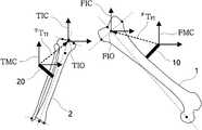
도 3에서 FIC(Femur Implant Coordinate)는 대퇴골 임플란트 원점(Femur Implant Origin, FIO)의 위치와 자세를 기준으로 하는 좌표계를 의미하고, FMC(Femur Marker Coordinate)는 대퇴골 마커(10)의 위치와 자세를 기준으로 하는 좌표계를 의미한다. 여기서, 대퇴골 임플란트 원점은 대퇴골의 수술 경로 즉, 절삭경로의 원점을 의미한다.In FIG. 3, FIC (Femur Implant Coordinate) refers to a coordinate system based on the position and posture of the femur implant origin (FIO), and FMC (Femur Marker Coordinate) refers to the position and posture of the
수술 대상체 정합부(151)는 프로브를 대퇴골(1)의 다수의 포인트에 접촉시켜 긁어가면서 대퇴골(1)과 대퇴골 마커(10)의 위치 및 자세 정보를 취득하고 이를 CT 영상과 정합하여, 대퇴골 마커(10)와 대퇴골 임플란트 원점(FIO)의 위치/자세에 관한 상관관계, 예컨대, 대퇴골 마커(10)의 좌표계와 대퇴골 임플란트 원점(FIO)을 기준으로 하는 좌표계(FIC) 간의 위치/자세에 관한 좌표변환관계로서의 변환행렬(FTFI)을 도출할 수 있다. 이를 통해, 제어부(150)는 추적기(40)로부터 대퇴골 마커(10)의 위치와 자세정보를 획득하면, 대퇴골 마커(10)의 위치와 자세정보에 수술 대상체 정합부(151)에서 도출한 변환행렬(FTFI)을 곱하여 대퇴골(1)의 임플란트 원점을 비롯한 대퇴골(1)의 위치와 자세를 도출할 수 있다.The surgical
도 3에서 TIC(Tibia Implant Coordinate)는 경골(2)의 임플란트 원점(Tibia Implant Origin, TIO)의 위치와 자세를 기준으로 하는 좌표계를 의미하고, TMC(Tibia Marker Coordinate)는 경골마커(20)의 위치와 자세를 기준으로 한 좌표계를 의미한다. 여기서, 경골(2)의 임플란트 원점은 수술 경로 즉, 절삭경로의 원점을 의미한다.In FIG. 3, Tibia Implant Coordinate (TIC) refers to a coordinate system based on the position and posture of the Tibia Implant Origin (TIO) of the
수술 대상체 정합부(151)는 프로브를 경골(2)의 다수의 포인트에 접촉시켜 긁어가면서 경골(2)과 경골 마커(20)의 위치 및 자세 정보를 취득하고 이를 CT 영상과 정합하여, 경골마커(20)와 경골 임플란트 원점(Tibia Implant Origin, TIO) 간의 위치/자세의 상관관계, 예컨대, 경골마커(20)의 좌표계와 경골 임플란트 원점(Tibia Implant Origin, TIO)을 기준으로 하는 좌표계 간의 위치/자세에 관한 좌표변환관계인 변환행렬(TTTI)을 도출한다. 이에 의해, 제어부(150)는 추적기(40)로부터 경골마커(20)에 관한 위치와 자세정보를 획득하면, 경골마커(20)의 위치와 자세정보에 수술 대상체 정합부(151)에서 도출한 변환행렬(TTTI)을 곱하여 경골(2)의 임플란트 원점을 비롯한 경골(2)의 위치와 자세를 도출할 수 있다.The surgical
여기서, 수술 대상체인 대퇴골(1)과 경골(2)의 위치 및 자세는 임플란트 원점을 기준으로 하는 수술 경로(예컨대, 절삭 경로)를 포함하는 의미로서, 대퇴골(1)과 경골(2)의 수술경로 상의 다수의 포인트의 위치 및 자세를 포함할 수 있다. 본 명세서에서 '수술 대상체'는 대퇴골(1)과 경골(2) 등 수술대상의 광의적인 의미로도 사용되고, 수술 대상체의 임플란트 원점의 위치 및 자세 또는 임플란트 원점을 기준으로 한 수술 경로를 포함하는 임플란트 수술 부위를 나타내는 협의의 의미로도 사용된다.Here, the position and posture of the femur (1) and tibia (2), which are the objects to be operated on, are meant to include a surgical path (e.g., a cutting path) based on the implant origin, and surgery on the femur (1) and tibia (2). It may include the location and posture of multiple points on the path. In the present specification, the term'surgical object' is also used in a broad sense of an operation object such as the femur (1) and tibia (2), and an implant including the position and posture of the implant origin of the object to be operated or a surgical path based on the implant origin. It is also used in the meaning of consultation to indicate the surgical site.
로봇 정합부(153)는 수술 로봇(30)에 설치된 로봇 마커(31)와 수술 로봇(30) 간의 위치 및 자세에 관한 상관관계를 도출하고, 로봇 마커(31)와 기 설정된 수술 가능 영역 간의 위치 및 자세에 관한 상관관계를 도출한다. 로봇 정합부(153)는 위치 정합을 위한 소프트웨어 알고리즘을 포함하여 구현될 수 있다.The
도 4는 본 발명의 일 실시예에 따른 로봇 정합부(153)의 동작을 설명하기 위한 도면이다. 도 4를 참조하면, RC(Robot Coordinate)는 로봇 좌표 원점(Robot Coordinate Origin, RO)을 기준으로 하는 로봇 기준 좌표계이고, WSC(Work Space Coordinate)는 수술 로봇(30)의 수술 가능 영역 원점(WS, Work Space)의 좌표계를 의미하며, RMC(Robot Marker Coordinate)는 로봇 마커(31)의 좌표계를 의미한다. 수술 로봇(30)의 수술 가능 영역(WS)은 수술 로봇(30)의 위치와 자세에 의해 결정되는 영역으로서, 수술 로봇(30)과 수술 가능 영역 간의 위치/자세의 상관관계는 로봇 좌표계 원점으로부터 미리 정의되어 있으며, 예컨대 로봇 좌표계 원점에 대한 수술가능영역의 좌표변환관계로서 변환행렬(ROTWS)값을 갖는다.4 is a view for explaining the operation of the
여기서, 수술 가능 영역은 수술 로봇(30)의 위치 및 자세정보에 기초하여 산출되는 미리 정의된 영역으로서, 수술 가능 자세 영역과 수술 가능 위치 영역을 포함한다. 수술 가능 위치 영역은 수술 가능 영역의 원점을 기준으로 일정 거리 또는 일정 볼륨을 갖도록 정의된 공간 영역을 의미하며, 수술 가능 위치 영역은 수술 로봇(30)의 자세에 기초하여 결정된다. 예컨대, 수술 가능 영역의 원점은 수술 로봇(30)의 위치로부터 미리 정의된 위치로 산출되고, 수술 가능 위치 영역은 이로부터 일정 볼륨을 갖는 영역으로 설정된다. 또한, 수술 가능 영역의 원점의 자세는 로봇 베이스의 자세와 동일한 것으로 설정되고, 수술 가능 자세 영역은 원점의 자세(즉, 로봇 베이스의 자세)로부터 수술 가능 자세 범위를 고려하여 일정 자세 범위로 설정될 수 있다. 예컨대, 수술 가능 영역은 로봇 암에 장착되는 수술 툴의 가능한 위치 및 자세 영역으로서, 로봇 베이스를 기준으로 정의될 수 있다.Here, the operable area is a predefined area calculated based on the position and posture information of the
로봇 정합부(153)는 정합을 통해 로봇 마커(31)와 수술 로봇(30)의 원점 간의 위치관계 즉, 로봇 마커(31)의 좌표계와 수술 로봇(30)의 좌표계 간의 위치/자세의 좌표변환관계인 변환행렬(RMTRO)을 도출한다. 로봇 정합부(153)는 추적기(40)를 통해 수술 로봇(30)의 위치와 로봇 마커(31)의 위치를 등록하고 그 상관관계를 도출할 수 있다. 로봇 정합부(153)는 로봇의 암에 로봇 마커(31)를 부착하고, 로봇 암을 움직이면서 로봇 마커(31)의 위치 및 자세를 추적기(40)를 통해 추적함으로써 로봇 베이스의 위치/자세와 로봇 마커(31)의 위치/자세 간의 상관관계인 변환행렬(RMTRO)를 도출할 수 있다.The
로봇 정합부(153)는 로봇 마커(31)에 대한 로봇 좌표 원점의 변환행렬(RMTRO)과 수술 로봇(30)의 원점에 대한 수술 가능 영역의 변환행렬(ROTWS)에 기초하여 로봇 마커(31)와 수술 가능 영역 간의 위치/자세의 상관관계를 도출한다. 이를 수식으로 나타내면 다음과 같다.The
[수학식 1][Equation 1]

(여기서,RMTWS는 로봇 마커(31)에 대한 수술 가능 영역의 변환행렬을 의미하고,RMTRO는 로봇 마커(31)에 관한 수술 로봇(30)의 원점의 변환행렬을 의미하며,ROTWS는 수술 로봇(30)의 원점에 관한 수술 가능 영역의 변환행렬을 의미한다.)(Here,RM TWS refers to the transformation matrix of the operable area for the
이에 의해, 제어부(150)는 추적기(40)로부터 로봇 마커(31)의 위치와 자세정보를 획득하고, 로봇 마커(31)의 위치와 자세정보에 로봇 정합부(153)에서 도출한 변환행렬(RMTWS)을 곱하여 수술 로봇(30)의 수술 가능 영역의 원점의 위치 및 자세를 도출할 수 있다. 제어부(150)는 수술 가능 영역의 원점의 위치 및 자세로부터 수술 가능 위치 영역과 자세 영역을 도출한다. 전술한 바와 같이, 수술 가능 영역은 수술 가능 영역의 원점으로부터 일정 볼륨을 갖도록 정의된 수술 가능 위치 영역과 수술 로봇(30)의 자세에 따른 수술 가능 자세 영역을 의미하는 것으로, 수술 로봇(30)의 위치나 자세에 의해 결정될 수 있다.Accordingly, the
수술 영역 확인부(155)는 대상체 마커(10, 20)와 로봇 마커(31)의 위치 및 자세정보에 기초하여 수술 대상체(1, 2)와 상기 수술 가능 영역 간의 위치/자세에 관한 상관관계를 도출한다. 수술 영역 확인부(155)는 위치/자세 변환 및 산출을 위한 소프트웨어 알고리즘에 의해 구현될 수 있다.The operation
도 5는 본 발명의 일 실시예에 따른 수술 영역 확인부(155)의 동작을 설명하기 위한 도면이다.5 is a view for explaining the operation of the operation
수술 영역 확인부(155)는 대퇴골(1)과 경골(2)에 부착된 대상체 마커(10, 20)와 수술 로봇(30)의 베이스에 설치된 로봇 마커(31)에 관한 위치 및 자세정보를 추적기(40)를 통해 획득하고, 이를 이용하여 수술 로봇(30)의 수술 가능 영역과 수술 대상체(1, 2)의 위치/자세에 상관관계를 확인한다.The operation
수술 영역 확인부(155)는 추적기(40)로부터 로봇 마커(31)와 대상체 마커(10, 20)의 위치 및 자세 정보를 획득한다. 도 5에서 OTC는 추적기(40)의 좌표계를 의미하며, RMC(Robot Marker Coordinate)는 로봇 마커(31)의 좌표계, FMC(Femur Marker Coordinate)는 대퇴골 마커(10)의 좌표계, TMC(Tibia Marker Coordinate)는 경골 마커(20)의 좌표계를 의미한다. 추적기(40)로부터 획득되는 대퇴골 마커(10)와 경골 마커(20)의 위치/자세정보는 모두 추적기(40) 좌표계를 기준으로 하여 획득한 값으로서, 추적기(40)의 좌표계와 로봇 마커(31) 및 대상체 마커(10, 20)의 좌표계 변환관계(OTSTRM,OTSTTM,OTSTFM)에 기초하여 로봇 마커(31)와 대상체 마커(10, 20)의 위치가 추적기(40) 좌표계를 기준으로 변환될 수 있다.The operation
수술 영역 확인부(155)는 추적기(40) 좌표계를 기준으로 변환된 대퇴골 마커(10)의 위치 및 자세정보에, 전술한 수술 대상체 정합부(151)에서 산출한 대퇴골 마커(10)에 대한 대퇴골 임플란트 원점(FIO) 간의 상관관계인 변환행렬(FTFI)을 곱하여 추적기(40) 좌표계를 기준으로 한 대퇴골(1)의 위치와 자세를 도출한다.The operation
동일한 방법으로, 수술 영역 확인부(155)는 추적기(40) 좌표계를 기준으로 변환된 경골마커(20)의 위치 및 자세정보에, 전술한 수술 대상체 정합부(151)에서 산출한 경골마커(20)에 대한 경골 임플란트 원점 간의 위치/자세의 상관관계인 변환행렬(TTTI)을 곱하여 추적기(40) 좌표계를 기준으로 한 경골(2)의 위치와 자세를 도출한다.In the same way, the operation
수술 영역 확인부(155)는 추적기(40) 좌표계를 기준으로 변환된 로봇 마커(31)의 위치 및 자세정보에, 전술한 로봇 정합부(153)에서 산출한 로봇 마커(31)에 대한 수술 가능 영역의 상관관계인 변환행렬(RMTWS)을 곱하여 추적기(40) 좌표계를 기준으로 한 수술 가능 영역의 원점의 위치(수술 가능 위치 영역) 및 자세(수술 가능 자세 영역)을 도출한다.The operation
대퇴골(1) 및 경골(2)의 위치/자세, 수술 가능 영역의 위치/자세는 모두 추적기(40)의 좌표계를 기준으로 한 값으로, 수술 영역 확인부(155)는 이 값들을 기초로 대퇴골(1) 및 경골(2)과 수술 가능 영역 간의 위치/자세에 관한 상관관계를 도출할 수 있다. 도 5를 참조하면, 수술 영역 확인부(155)는 수술 가능 영역에 관한 대퇴골과 경골의 위치 및 자세의 상관관계, 예컨대 위치변환관계인 변환행렬(WSTFIC,WSTTIC)을 도출한다.The position/position of the femur (1) and tibia (2) and the position/position of the operable area are all values based on the coordinate system of the
도 3 내지 도 5에서 대퇴골(1)의 임플란트 원점과 경골(2)의 임플란트 원점은 수술 경로 즉, 절삭경로의 원점을 의미한다. 수술경로는 수술전에 미리 계획되는 것으로, 대퇴골(1)과 경골(2)의 절삭범위나 임플란트의 종류 등에 따라 달리 설정될 수 있다. 수술 경로, 예컨대 절삭경로에 관한 정보는 미리 저장되지만, 수술경로에 따른 임플란트 원점의 위치와 자세는 수술 대상체와 수술 로봇(30)의 위치/자세에 따라 상대적으로 정의된다.3 to 5, the implant origin of the femur (1) and the implant origin of the tibia (2) refer to the surgical path, that is, the origin of the cutting path. The surgical path is pre-planned before surgery, and may be set differently depending on the cutting range of the femur (1) and tibia (2) or the type of implant. Information on the surgical path, for example, the cutting path is stored in advance, but the position and posture of the implant origin according to the surgery path is relatively defined according to the position/position of the surgical object and the
위와 같은 과정을 통해, 본 발명에서는 수술 로봇(30)의 위치/자세에 따른 수술 가능 영역과 수술 대상체(1, 2)의 위치/자세에 따른 수술경로, 예컨대 수술 경로의 원점의 위치/자세를 산출하고 이들의 상관관계를 산출한다.Through the above process, in the present invention, the operation path according to the position/posture of the
GUI 생성부(157)는 수술 대상체(1, 2)의 위치/자세와 수술 가능 위치 영역/ 자세 영역 간의 상관관계에 관한 가이드정보를 그래픽으로 생성하여 디스플레이부(130)로 전달한다. GUI 생성부(157)는 데이터를 처리하여 영상으로 생성하는 그래픽 처리모듈 예컨대, 그래픽 카드를 포함할 수 있다. 도 6은 본 발명의 일 실시예에 따른 GUI 생성부(157)가 생성하여 디스플레이부(130)에 표시된 가이드정보의 일 예를 도시한 것이다. 도 6을 참조하면, 가이드정보는 수술 대상체(1, 2)의 자세가 수술 가능 자세 영역에 속하는지 여부를 나타내는 제1 메뉴화면(201)과, 상기 수술 대상체(1, 2)의 위치가 수술 가능 위치 영역에 속하는지 여부를 나타내는 제2 메뉴화면(202), 및 수술 로봇(30)의 이동 방향을 제시하는 제3 메뉴화면(203)을 포함한다. 또한, 가이드정보는 제2 메뉴화면에서와 같이 수술 대상체의 위치와 수술 가능 영역 간의 이격 거리 정보를 시각적으로 나타낼 수 있다.The
제1 메뉴화면(201)을 보면, 수술 대상체(1, 2)의 자세(회전각도)가 수술 가능 자세 영역에 속했는지 그래픽적으로 보여준다. 제1 메뉴화면(201)에서 점(201a)은 현재의 대퇴골(1)과 경골(2)의 자세(회전각도)를 나타내고 색상으로 표현된 바(201b)는 수술 가능 자세 영역을 나타낸다. 따라서, 사용자는 대퇴골(1)과 경골(2)의 자세(회전각도)를 나타내는 점(201a)이 수술 가능 자세 영역을 나타내는 색상 바(201b) 안에 있는지 밖에 있는지 여부를 확인하면서, 수술 대상체(1, 2)의 자세 또는 수술 로봇(30)의 자세를 수술 가능 자세에 속하도록 적절히 조정할 수 있다. 제1 메뉴화면(201)에 도시된 바와 같이, 수술 대상체(1, 2)의 자세는 3축, 예컨대 X축, Y축, Z축에 관한 회전각도로서, Angle1, Angle2, Angle3 3개의 자세로 각각 표시된다.Looking at the
제2 메뉴화면(202)를 보면, 수술 대상체(1, 2)의 위치와 수술 가능 영역(WS)의 위치관계가 도시되어 있다. 위치관계는 전면이나 평면 등 다양한 위치에서 바라본 위치 관계를 도시하여, 수술 가능 영역에 수술 대상체(1, 2)가 위치하도록 수술 로봇(30)을 이동시킬 수 있도록 가이드한다. 도 6에서, 수술 대상체(1, 2)의 위치는 수술 대상체(1, 2)의 임플란트 원점을 포함하며, 미리 계획된 수술 경로에 기초하여 수술 대상체(1, 2)에서 상기 수술 경로의 원점을 기준으로 수술 경로에 포함되는 영역을 포함하여 표현될 수 있다.Looking at the
제3 메뉴화면(203)은 수술 대상체(1, 2)와 로봇의 이동방향을 도식화하여 표현하고 있으며, 현재의 수술 대상체(1, 2)의 위치와 수술 로봇(30)의 위치관계에 기초하여 로봇의 이동방향을 전후좌우 화살표를 활성화하는 방식으로 표시해줄 수 있다. 사용자는 제3 메뉴화면에서 시각적으로 제시하는 수술 로봇(30)의 전후좌우 화살표의 이동방향에 따라 수술 로봇(30)을 이동시킴으로써 수술 대상체(1, 2)가 수술 가능 영역(WS)에 속하도록 가이드할 수 있다.The
여기서, 수술 가능 영역(WS)과 수술 대상체(1, 2)의 위치 및 자세의 상관관계는 로봇의 좌표계를 기준으로 표현될 수 있다.Here, the correlation between the position and posture of the operable area WS and the
이와 같이, 본 발명은 수술 로봇(30)의 위치/자세에 따른 수술 가능 영역(예, 수술 가능 위치 영역, 수술 가능 자세 영역)과, 수술 대상체(1, 2)의 위치/자세에 따른 수술 경로의 위치/자세의 상관관계정보를 그래픽적으로 표시함으로써, 사용자가 수술 대상체(1, 2)가 실제 수술 작업 영역(예, 수술 경로)이 수술 가능 영역 내에 위치되도록 수술 대상체(1, 2)와 수술 로봇(30)의 위치 및 자세를 조정하도록 가이드해줄 수 있다.As described above, the present invention provides an operable area (eg, an operable position area, an operable posture area) according to the position/position of the
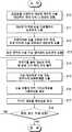
도 7은 본 발명의 일 실시예에 따른 로봇 위치 가이드 장치(100)에 의한 위치 가이드 방법을 설명하기 위한 흐름도이다. 전술한 실시예와 중복되는 설명은 생략하기로 하다.7 is a flowchart illustrating a method of guiding a position by the robot
도 7을 참조하면, 본 발명의 일 실시예에 따른 수술 로봇의 위치 가이드 방법은 먼저 프로브를 이용하여 대상체 마커(10, 20)와 수술 대상체(1, 2)의 위치를 인식하는 과정을 통해, 수술전에 미리 획득한 환자의 CT 영상과 정합을 수행한다(S10). 이와 같은 정합 과정을 통해 대상체 마커(10, 20)와 수술 대상체(1, 2) 간의 위치/자세에 관한 상관관계를 도출한다(S11). 또한, 로봇 마커(31)와 수술 로봇(30)의 정합과정을 통해, 로봇 마커(31)와 수술 로봇(30) 간의 위치/자세에 관한 상관관계를 도출한다(S12). 그리고, 수술 로봇(30)의 위치/자세에 의해 미리 정의된 수술 가능 영역과의 상관관계를 이용하여, 로봇 마커(31)와 수술 가능 영역과의 상관관계를 도출한다(S13).Referring to FIG. 7, in a method of guiding a position of a surgical robot according to an embodiment of the present invention, first, through a process of recognizing the positions of the
추적기(40)를 통해 대상체 마커(10, 20) 및 로봇 마커(31)의 위치 및 자세를 획득하고(S14), 전술한 정합과정에서 산출한 대상체 마커(10, 20)와 수술 대상체(1, 2)의 위치 및 자세의 상관관계, 및 로봇 마커(31)와 수술 가능 영역 간의 위치 및 자세의 상관관계를 이용하여 수술 대상체(1, 2)의 위치/자세와 수술 가능 영역과의 위치 및 자세의 상관관계를 도출한다(S15).The position and posture of the
GUI 생성부(157)는 산출한 상관관계를 수술 로봇(30)(또는 수술 대상체)의 위치 및 자세를 가이드하는 가이드정보로 생성하고(S16), 디스플레이부(130)는 가이드정보를 영상으로 표시한다(S17).The
만약, 수술 로봇(30)의 위치/자세 또는 수술 대상체(1, 2)의 위치/자세가 조정되는 경우(S18), 로봇의 위치 가이드 장치(100)는 추적기(40)를 통해 변경된 대상체 마커(10, 20) 또는 로봇 마커(31)의 위치/자세 정보를 수신하여 전술한 S14~S17 단계를 수행하여 변경된 위치/자세에 따른 가이드정보를 다시 생성하여 표시한다(S17).If the position/posture of the
다른 실시예에 따르면, 전술한 도 7에서 로봇 정합과정(S12~S14)은 수술 대상체 정합과정(S10, S11)보다 먼저 수행될 수도 있다.According to another embodiment, the robot registration process (S12 to S14) in FIG. 7 may be performed prior to the operation object registration process (S10, S11).
전술한 과정을 통해 수술 대상체(1, 2)의 위치/자세가 수술 가능 영역 안에 속하게 되는 것을 확인한 후에 안전하게 수술을 시작할 수 있다. 이와 같이, 본 발명에 따르면, 수술 로봇(30)이 수술 가능한 위치 및 자세로 이동하도록 가이드함으로써, 수술 중단의 위험을 최소화할 수 있다. 전술한 실시예에서는 로봇의 수술 가능 영역(위치영역, 자세영역)과 수술 대상체(1, 2) 간의 위치/자세의 상관관계를 도출하여 이를 시각적으로 표시하는 것으로 설명하였으나, 다른 실시예에 따르면 수술 로봇(30)의 위치/자세와 수술 대상체(1, 2)의 위치/자세의 상관관계를 도출하여 이를 시각적으로 표시할 수도 있다.After confirming that the position/position of the
수술 가능 영역은 수술 로봇(30)의 위치 및 자세에 따라 결정되는 영역이므로, 전술한 실시예와 동일한 변환과정을 통해 수술 로봇(30)의 위치/자세와 수술 대상체(1, 2)의 위치/자세의 상관관계를 도출할 수 있다. 예를 들어, 수술 가능 영역 대신에 로봇 베이스의 위치 및 자세를 도출하고, 수술 대상체(1, 2)의 위치/자세에 따른 수술 가능한 로봇 베이스 위치/자세 영역과 현재 로봇의 위치/자세를 도시함으로써 사용자가 목표 위치로 로봇을 이동하도록 가이드 할 수 있다.Since the operable area is an area determined according to the position and posture of the
Claims (12)
Translated fromKoreanPriority Applications (4)
| Application Number | Priority Date | Filing Date | Title |
|---|---|---|---|
| JP2022513627AJP7341567B2 (en) | 2019-09-05 | 2020-09-03 | Robot position guide device and system including it |
| EP20860074.2AEP4026509A4 (en) | 2019-09-05 | 2020-09-03 | DEVICE FOR THE POSITION GUIDE OF A ROBOT, METHOD AND SYSTEM WITH THIS DEVICE |
| CN202080062005.0ACN114364333B (en) | 2019-09-05 | 2020-09-03 | Device, method for guiding a robot position and system comprising such a device |
| US17/640,509US11666392B2 (en) | 2019-09-05 | 2020-09-03 | Device for guiding position of robot, method therefor, and system including the same |
Applications Claiming Priority (2)
| Application Number | Priority Date | Filing Date | Title |
|---|---|---|---|
| KR1020190109922AKR102274167B1 (en) | 2019-09-05 | 2019-09-05 | Robot positioning guide apparautus, method therof and system comprising the same |
| KR10-2019-0109922 | 2019-09-05 |
Publications (2)
| Publication Number | Publication Date |
|---|---|
| WO2021045546A2true WO2021045546A2 (en) | 2021-03-11 |
| WO2021045546A3 WO2021045546A3 (en) | 2021-04-29 |
Family
ID=74852140
Family Applications (1)
| Application Number | Title | Priority Date | Filing Date |
|---|---|---|---|
| PCT/KR2020/011895CeasedWO2021045546A2 (en) | 2019-09-05 | 2020-09-03 | Device for guiding position of robot, method therefor, and system comprising same |
Country Status (6)
| Country | Link |
|---|---|
| US (1) | US11666392B2 (en) |
| EP (1) | EP4026509A4 (en) |
| JP (1) | JP7341567B2 (en) |
| KR (1) | KR102274167B1 (en) |
| CN (1) | CN114364333B (en) |
| WO (1) | WO2021045546A2 (en) |
Families Citing this family (6)
| Publication number | Priority date | Publication date | Assignee | Title |
|---|---|---|---|---|
| KR102301863B1 (en)* | 2020-02-12 | 2021-09-16 | 큐렉소 주식회사 | A method for verifying a spatial registration of a surgical target object, the apparatus therof and the system comprising the same |
| EP4114299A1 (en)* | 2020-06-03 | 2023-01-11 | Covidien LP | Surgical robotic system user interfaces |
| TWI790181B (en)* | 2022-08-03 | 2023-01-11 | 國立陽明交通大學 | Surgical robot system |
| KR102841596B1 (en)* | 2022-09-23 | 2025-08-04 | 큐렉소 주식회사 | Apparatus for planning cutting path of surgical robot, and mehtod thereof |
| KR102777950B1 (en)* | 2022-12-12 | 2025-03-11 | 큐렉소 주식회사 | Apparatus for generating operable area of surgical robot and method thereof |
| KR20240142083A (en)* | 2023-03-21 | 2024-09-30 | 주식회사 코렌텍 | Surgical Assistant Robotic System and Position Control Method through it |
Family Cites Families (20)
| Publication number | Priority date | Publication date | Assignee | Title |
|---|---|---|---|---|
| US8644907B2 (en) | 1999-10-28 | 2014-02-04 | Medtronic Navigaton, Inc. | Method and apparatus for surgical navigation |
| WO2006091494A1 (en)* | 2005-02-22 | 2006-08-31 | Mako Surgical Corp. | Haptic guidance system and method |
| US8311611B2 (en) | 2007-04-24 | 2012-11-13 | Medtronic, Inc. | Method for performing multiple registrations in a navigated procedure |
| KR100998182B1 (en) | 2008-08-21 | 2010-12-03 | (주)미래컴퍼니 | 3D display system of surgical robot and its control method |
| EP2996615B1 (en)* | 2013-03-13 | 2019-01-30 | Stryker Corporation | System for arranging objects in an operating room in preparation for surgical procedures |
| WO2014198796A1 (en)* | 2013-06-11 | 2014-12-18 | Minmaxmedical | System for positioning a surgical device |
| DE102014219477B4 (en)* | 2014-09-25 | 2018-06-21 | Deutsches Zentrum für Luft- und Raumfahrt e.V. | Surgery robotic system |
| KR102296451B1 (en) | 2014-12-08 | 2021-09-06 | 큐렉소 주식회사 | CT-Robot Registration System for Interventional Robot |
| CN108472096B (en)* | 2015-12-31 | 2021-11-16 | 史赛克公司 | System and method for performing a procedure on a patient at a target site defined by a virtual object |
| AU2017224228B2 (en) | 2016-02-26 | 2022-03-24 | Think Surgical, Inc. | Method and system for guiding user positioning of a robot |
| CN110786819B (en)* | 2016-03-30 | 2022-07-26 | 索尼公司 | Surgical imaging system |
| KR101817438B1 (en) | 2016-09-13 | 2018-01-11 | 재단법인대구경북과학기술원 | A surgical navigation system for total hip arthroplasty |
| AU2017378250B2 (en)* | 2016-12-16 | 2023-09-28 | Mako Surgical Corp. | Techniques for detecting errors or loss of accuracy in a surgical robotic system |
| US10499997B2 (en)* | 2017-01-03 | 2019-12-10 | Mako Surgical Corp. | Systems and methods for surgical navigation |
| CN117017492A (en)* | 2017-09-27 | 2023-11-10 | 虚拟切割有限公司 | Robotic surgical device with tracking camera technology and related systems and methods |
| US11154369B2 (en)* | 2018-01-24 | 2021-10-26 | Think Surgical, Inc. | Environmental mapping for robotic assisted surgery |
| US11612438B2 (en)* | 2018-09-05 | 2023-03-28 | Point Robotics Medtech Inc. | Navigation system and method for medical operation by a robotic system using a tool |
| IL281716B2 (en)* | 2018-09-27 | 2025-05-01 | Quantum Surgical | Medical robot comprising automatic positioning means |
| US11986246B2 (en)* | 2019-06-25 | 2024-05-21 | Think Surgical, Inc. | Method to determine bone placement in a robot workspace |
| WO2021257681A1 (en)* | 2020-06-19 | 2021-12-23 | Smith & Nephew, Inc. | Robotic arm positioning and movement control |
- 2019
- 2019-09-05KRKR1020190109922Apatent/KR102274167B1/enactiveActive
- 2020
- 2020-09-03JPJP2022513627Apatent/JP7341567B2/enactiveActive
- 2020-09-03EPEP20860074.2Apatent/EP4026509A4/enactivePending
- 2020-09-03CNCN202080062005.0Apatent/CN114364333B/enactiveActive
- 2020-09-03WOPCT/KR2020/011895patent/WO2021045546A2/ennot_activeCeased
- 2020-09-03USUS17/640,509patent/US11666392B2/enactiveActive
Also Published As
| Publication number | Publication date |
|---|---|
| US20220265364A1 (en) | 2022-08-25 |
| KR102274167B1 (en) | 2021-07-12 |
| JP2022545743A (en) | 2022-10-28 |
| EP4026509A4 (en) | 2023-08-30 |
| CN114364333A (en) | 2022-04-15 |
| KR20210029322A (en) | 2021-03-16 |
| US11666392B2 (en) | 2023-06-06 |
| CN114364333B (en) | 2024-08-20 |
| EP4026509A2 (en) | 2022-07-13 |
| JP7341567B2 (en) | 2023-09-11 |
| WO2021045546A3 (en) | 2021-04-29 |
Similar Documents
| Publication | Publication Date | Title |
|---|---|---|
| WO2021045546A2 (en) | Device for guiding position of robot, method therefor, and system comprising same | |
| WO2021206372A1 (en) | Two-dimensional medical image-based spinal surgery planning apparatus and method | |
| US11737831B2 (en) | Surgical object tracking template generation for computer assisted navigation during surgical procedure | |
| US11850010B2 (en) | Workflow systems and methods for enhancing collaboration between participants in a surgical procedure | |
| EP3618748B1 (en) | Surgical navigation system | |
| US20210169582A1 (en) | Navigation surgical system, registration method thereof and electronic device | |
| WO2016195401A1 (en) | 3d glasses system for surgical operation using augmented reality | |
| JP2021171657A (en) | Alignment of surgical instruments with reference arrays tracked by cameras in augmented reality headsets for assisted navigation during surgery | |
| WO2010021447A1 (en) | Three-dimensional display system for surgical robot and method for controlling same | |
| JP2021194539A (en) | Camera tracking bar for computer-aided navigation during surgery | |
| US20180303558A1 (en) | Methods and systems for registration of virtual space with real space in an augmented reality system | |
| WO2019132427A1 (en) | Laser target projection apparatus and control method thereof, and laser surgery induction system comprising laser target projection apparatus | |
| WO2014077613A1 (en) | Robot for repositioning procedure, and method for controlling operation thereof | |
| US12201375B2 (en) | Extended reality systems for visualizing and controlling operating room equipment | |
| WO2020185049A2 (en) | System and method for planning pedicle screw fixation | |
| WO2021153973A1 (en) | Device for providing joint replacement robotic surgery information and method for providing same | |
| WO2014112782A1 (en) | Tracking system and tracking method using same | |
| WO2021162287A1 (en) | Method for verifying matching of surgery target, apparatus therefor, and system including same | |
| WO2013105738A1 (en) | Surgical robot control apparatus and method for controlling same | |
| WO2012108578A1 (en) | System for bone motion monitoring and path correction using a three-dimensional optical measuring unit | |
| WO2021054659A2 (en) | Device and method for surgical navigation | |
| WO2024063539A1 (en) | Apparatus for planning cutting path of surgical robot, and method thereof | |
| WO2025053337A1 (en) | 2d image-based automatic surgery planning method and system | |
| WO2016195265A1 (en) | Surgical path setting device, surgical robot system comprising same and surgical path setting method for surgical robot | |
| US11232861B1 (en) | Systems and methods for displaying predetermined information for clinical use |
Legal Events
| Date | Code | Title | Description |
|---|---|---|---|
| 121 | Ep: the epo has been informed by wipo that ep was designated in this application | Ref document number:20860074 Country of ref document:EP Kind code of ref document:A2 | |
| ENP | Entry into the national phase | Ref document number:2022513627 Country of ref document:JP Kind code of ref document:A | |
| NENP | Non-entry into the national phase | Ref country code:DE | |
| ENP | Entry into the national phase | Ref document number:2020860074 Country of ref document:EP Effective date:20220405 |