WO2021045369A1 - Arthroscopic bleeding control device - Google Patents
Arthroscopic bleeding control deviceDownload PDFInfo
- Publication number
- WO2021045369A1 WO2021045369A1PCT/KR2020/008834KR2020008834WWO2021045369A1WO 2021045369 A1WO2021045369 A1WO 2021045369A1KR 2020008834 WKR2020008834 WKR 2020008834WWO 2021045369 A1WO2021045369 A1WO 2021045369A1
- Authority
- WO
- WIPO (PCT)
- Prior art keywords
- hemostatic
- block
- winding
- band
- lead wire
- Prior art date
- Legal status (The legal status is an assumption and is not a legal conclusion. Google has not performed a legal analysis and makes no representation as to the accuracy of the status listed.)
- Ceased
Links
Images


Classifications
- A—HUMAN NECESSITIES
- A61—MEDICAL OR VETERINARY SCIENCE; HYGIENE
- A61B—DIAGNOSIS; SURGERY; IDENTIFICATION
- A61B17/00—Surgical instruments, devices or methods
- A61B17/12—Surgical instruments, devices or methods for ligaturing or otherwise compressing tubular parts of the body, e.g. blood vessels or umbilical cord
- A61B17/12009—Implements for ligaturing other than by clamps or clips, e.g. using a loop with a slip knot
- A61B17/12013—Implements for ligaturing other than by clamps or clips, e.g. using a loop with a slip knot for use in minimally invasive surgery, e.g. endoscopic surgery
- A—HUMAN NECESSITIES
- A61—MEDICAL OR VETERINARY SCIENCE; HYGIENE
- A61B—DIAGNOSIS; SURGERY; IDENTIFICATION
- A61B17/00—Surgical instruments, devices or methods
- A61B17/12—Surgical instruments, devices or methods for ligaturing or otherwise compressing tubular parts of the body, e.g. blood vessels or umbilical cord
- A61B17/12022—Occluding by internal devices, e.g. balloons or releasable wires
- A61B17/12027—Type of occlusion
- A61B17/1204—Type of occlusion temporary occlusion
- A—HUMAN NECESSITIES
- A61—MEDICAL OR VETERINARY SCIENCE; HYGIENE
- A61B—DIAGNOSIS; SURGERY; IDENTIFICATION
- A61B17/00—Surgical instruments, devices or methods
- A61B17/12—Surgical instruments, devices or methods for ligaturing or otherwise compressing tubular parts of the body, e.g. blood vessels or umbilical cord
- A61B17/12022—Occluding by internal devices, e.g. balloons or releasable wires
- A61B17/12099—Occluding by internal devices, e.g. balloons or releasable wires characterised by the location of the occluder
- A—HUMAN NECESSITIES
- A61—MEDICAL OR VETERINARY SCIENCE; HYGIENE
- A61B—DIAGNOSIS; SURGERY; IDENTIFICATION
- A61B17/00—Surgical instruments, devices or methods
- A61B17/12—Surgical instruments, devices or methods for ligaturing or otherwise compressing tubular parts of the body, e.g. blood vessels or umbilical cord
- A61B17/12022—Occluding by internal devices, e.g. balloons or releasable wires
- A61B17/12131—Occluding by internal devices, e.g. balloons or releasable wires characterised by the type of occluding device
- A61B17/12181—Occluding by internal devices, e.g. balloons or releasable wires characterised by the type of occluding device formed by fluidized, gelatinous or cellular remodelable materials, e.g. embolic liquids, foams or extracellular matrices
- A61B17/1219—Occluding by internal devices, e.g. balloons or releasable wires characterised by the type of occluding device formed by fluidized, gelatinous or cellular remodelable materials, e.g. embolic liquids, foams or extracellular matrices expandable in contact with liquids
- A—HUMAN NECESSITIES
- A61—MEDICAL OR VETERINARY SCIENCE; HYGIENE
- A61B—DIAGNOSIS; SURGERY; IDENTIFICATION
- A61B17/00—Surgical instruments, devices or methods
- A61B17/56—Surgical instruments or methods for treatment of bones or joints; Devices specially adapted therefor
- A—HUMAN NECESSITIES
- A61—MEDICAL OR VETERINARY SCIENCE; HYGIENE
- A61F—FILTERS IMPLANTABLE INTO BLOOD VESSELS; PROSTHESES; DEVICES PROVIDING PATENCY TO, OR PREVENTING COLLAPSING OF, TUBULAR STRUCTURES OF THE BODY, e.g. STENTS; ORTHOPAEDIC, NURSING OR CONTRACEPTIVE DEVICES; FOMENTATION; TREATMENT OR PROTECTION OF EYES OR EARS; BANDAGES, DRESSINGS OR ABSORBENT PADS; FIRST-AID KITS
- A61F13/00—Bandages or dressings; Absorbent pads
- A61F13/15—Absorbent pads, e.g. sanitary towels, swabs or tampons for external or internal application to the body; Supporting or fastening means therefor; Tampon applicators
- A61F13/20—Tampons, e.g. catamenial tampons; Accessories therefor
- A61F13/2002—Tampons, e.g. catamenial tampons; Accessories therefor characterised by the use
- A—HUMAN NECESSITIES
- A61—MEDICAL OR VETERINARY SCIENCE; HYGIENE
- A61F—FILTERS IMPLANTABLE INTO BLOOD VESSELS; PROSTHESES; DEVICES PROVIDING PATENCY TO, OR PREVENTING COLLAPSING OF, TUBULAR STRUCTURES OF THE BODY, e.g. STENTS; ORTHOPAEDIC, NURSING OR CONTRACEPTIVE DEVICES; FOMENTATION; TREATMENT OR PROTECTION OF EYES OR EARS; BANDAGES, DRESSINGS OR ABSORBENT PADS; FIRST-AID KITS
- A61F13/00—Bandages or dressings; Absorbent pads
- A61F13/15—Absorbent pads, e.g. sanitary towels, swabs or tampons for external or internal application to the body; Supporting or fastening means therefor; Tampon applicators
- A61F13/20—Tampons, e.g. catamenial tampons; Accessories therefor
- A61F13/2051—Tampons, e.g. catamenial tampons; Accessories therefor characterised by the material or the structure of the inner absorbing core
- A61F13/2054—Tampons, e.g. catamenial tampons; Accessories therefor characterised by the material or the structure of the inner absorbing core made by compressing a not-rolled web or pledged
- A—HUMAN NECESSITIES
- A61—MEDICAL OR VETERINARY SCIENCE; HYGIENE
- A61F—FILTERS IMPLANTABLE INTO BLOOD VESSELS; PROSTHESES; DEVICES PROVIDING PATENCY TO, OR PREVENTING COLLAPSING OF, TUBULAR STRUCTURES OF THE BODY, e.g. STENTS; ORTHOPAEDIC, NURSING OR CONTRACEPTIVE DEVICES; FOMENTATION; TREATMENT OR PROTECTION OF EYES OR EARS; BANDAGES, DRESSINGS OR ABSORBENT PADS; FIRST-AID KITS
- A61F13/00—Bandages or dressings; Absorbent pads
- A61F13/15—Absorbent pads, e.g. sanitary towels, swabs or tampons for external or internal application to the body; Supporting or fastening means therefor; Tampon applicators
- A61F13/20—Tampons, e.g. catamenial tampons; Accessories therefor
- A61F13/2051—Tampons, e.g. catamenial tampons; Accessories therefor characterised by the material or the structure of the inner absorbing core
- A61F13/206—Tampons made of rolled-up material
- A—HUMAN NECESSITIES
- A61—MEDICAL OR VETERINARY SCIENCE; HYGIENE
- A61F—FILTERS IMPLANTABLE INTO BLOOD VESSELS; PROSTHESES; DEVICES PROVIDING PATENCY TO, OR PREVENTING COLLAPSING OF, TUBULAR STRUCTURES OF THE BODY, e.g. STENTS; ORTHOPAEDIC, NURSING OR CONTRACEPTIVE DEVICES; FOMENTATION; TREATMENT OR PROTECTION OF EYES OR EARS; BANDAGES, DRESSINGS OR ABSORBENT PADS; FIRST-AID KITS
- A61F13/00—Bandages or dressings; Absorbent pads
- A61F13/15—Absorbent pads, e.g. sanitary towels, swabs or tampons for external or internal application to the body; Supporting or fastening means therefor; Tampon applicators
- A61F13/20—Tampons, e.g. catamenial tampons; Accessories therefor
- A61F13/2051—Tampons, e.g. catamenial tampons; Accessories therefor characterised by the material or the structure of the inner absorbing core
- A61F13/2068—Tampons made from several layers
- A—HUMAN NECESSITIES
- A61—MEDICAL OR VETERINARY SCIENCE; HYGIENE
- A61F—FILTERS IMPLANTABLE INTO BLOOD VESSELS; PROSTHESES; DEVICES PROVIDING PATENCY TO, OR PREVENTING COLLAPSING OF, TUBULAR STRUCTURES OF THE BODY, e.g. STENTS; ORTHOPAEDIC, NURSING OR CONTRACEPTIVE DEVICES; FOMENTATION; TREATMENT OR PROTECTION OF EYES OR EARS; BANDAGES, DRESSINGS OR ABSORBENT PADS; FIRST-AID KITS
- A61F13/00—Bandages or dressings; Absorbent pads
- A61F13/15—Absorbent pads, e.g. sanitary towels, swabs or tampons for external or internal application to the body; Supporting or fastening means therefor; Tampon applicators
- A61F13/20—Tampons, e.g. catamenial tampons; Accessories therefor
- A61F13/26—Means for inserting tampons, i.e. applicators
- A61F13/266—Insertion devices, e.g. rods or plungers, separate from the tampon
- A—HUMAN NECESSITIES
- A61—MEDICAL OR VETERINARY SCIENCE; HYGIENE
- A61F—FILTERS IMPLANTABLE INTO BLOOD VESSELS; PROSTHESES; DEVICES PROVIDING PATENCY TO, OR PREVENTING COLLAPSING OF, TUBULAR STRUCTURES OF THE BODY, e.g. STENTS; ORTHOPAEDIC, NURSING OR CONTRACEPTIVE DEVICES; FOMENTATION; TREATMENT OR PROTECTION OF EYES OR EARS; BANDAGES, DRESSINGS OR ABSORBENT PADS; FIRST-AID KITS
- A61F13/00—Bandages or dressings; Absorbent pads
- A61F13/15—Absorbent pads, e.g. sanitary towels, swabs or tampons for external or internal application to the body; Supporting or fastening means therefor; Tampon applicators
- A61F13/36—Surgical swabs, e.g. for absorbency or packing body cavities during surgery
- A—HUMAN NECESSITIES
- A61—MEDICAL OR VETERINARY SCIENCE; HYGIENE
- A61B—DIAGNOSIS; SURGERY; IDENTIFICATION
- A61B17/00—Surgical instruments, devices or methods
- A61B17/12—Surgical instruments, devices or methods for ligaturing or otherwise compressing tubular parts of the body, e.g. blood vessels or umbilical cord
- A61B2017/12004—Surgical instruments, devices or methods for ligaturing or otherwise compressing tubular parts of the body, e.g. blood vessels or umbilical cord for haemostasis, for prevention of bleeding
- A—HUMAN NECESSITIES
- A61—MEDICAL OR VETERINARY SCIENCE; HYGIENE
- A61B—DIAGNOSIS; SURGERY; IDENTIFICATION
- A61B17/00—Surgical instruments, devices or methods
- A61B17/12—Surgical instruments, devices or methods for ligaturing or otherwise compressing tubular parts of the body, e.g. blood vessels or umbilical cord
- A61B17/12009—Implements for ligaturing other than by clamps or clips, e.g. using a loop with a slip knot
- A61B2017/12018—Elastic band ligators
- A—HUMAN NECESSITIES
- A61—MEDICAL OR VETERINARY SCIENCE; HYGIENE
- A61B—DIAGNOSIS; SURGERY; IDENTIFICATION
- A61B17/00—Surgical instruments, devices or methods
- A61B17/56—Surgical instruments or methods for treatment of bones or joints; Devices specially adapted therefor
- A61B2017/564—Methods for bone or joint treatment
- A—HUMAN NECESSITIES
- A61—MEDICAL OR VETERINARY SCIENCE; HYGIENE
- A61F—FILTERS IMPLANTABLE INTO BLOOD VESSELS; PROSTHESES; DEVICES PROVIDING PATENCY TO, OR PREVENTING COLLAPSING OF, TUBULAR STRUCTURES OF THE BODY, e.g. STENTS; ORTHOPAEDIC, NURSING OR CONTRACEPTIVE DEVICES; FOMENTATION; TREATMENT OR PROTECTION OF EYES OR EARS; BANDAGES, DRESSINGS OR ABSORBENT PADS; FIRST-AID KITS
- A61F13/00—Bandages or dressings; Absorbent pads
- A61F2013/00361—Plasters
- A61F2013/00365—Plasters use
- A61F2013/00463—Plasters use haemostatic
- A—HUMAN NECESSITIES
- A61—MEDICAL OR VETERINARY SCIENCE; HYGIENE
- A61F—FILTERS IMPLANTABLE INTO BLOOD VESSELS; PROSTHESES; DEVICES PROVIDING PATENCY TO, OR PREVENTING COLLAPSING OF, TUBULAR STRUCTURES OF THE BODY, e.g. STENTS; ORTHOPAEDIC, NURSING OR CONTRACEPTIVE DEVICES; FOMENTATION; TREATMENT OR PROTECTION OF EYES OR EARS; BANDAGES, DRESSINGS OR ABSORBENT PADS; FIRST-AID KITS
- A61F13/00—Bandages or dressings; Absorbent pads
- A61F13/15—Absorbent pads, e.g. sanitary towels, swabs or tampons for external or internal application to the body; Supporting or fastening means therefor; Tampon applicators
- A61F13/20—Tampons, e.g. catamenial tampons; Accessories therefor
- A61F13/2002—Tampons, e.g. catamenial tampons; Accessories therefor characterised by the use
- A61F2013/2014—Tampons, e.g. catamenial tampons; Accessories therefor characterised by the use for endoscopic procedures
Definitions
- the present inventionrelates to an arthroscopic bleeding control device, and more specifically, exhibits a stable adsorption and hemostatic effect on bleeding occurring in the joint cavity, and stably withdraws the hemostatic block expanded from the joint cavity without a separate tool due to the adsorption of the bleed It relates to a device that can control arthroscopic bleeding.
- the arthroscopyis a type of endoscope, and changes in the joint cavity can be directly observed or photographed.
- Such an arthroscopyenables accurate diagnosis by directly viewing the lesions in the joints through a small-diameter arthroscopy unit formed in the skin tissue without cutting the joints, and makes it possible to perform all types of surgery within the joints.
- arthroscopycan be used for knee surgery including loose body removal, meniscectomy or meniscal repair, synovectomy, reconstruction of cruciate anterior or posterior cruciate. ligament) and the like.
- arthroscopydoes not incise joints, it has many advantages such as less pain after surgery, quick recovery of joint movement and less complications from surgery, and reduced treatment costs, such as shoulders, elbows, hands, hips, knees, feet, and spine. It can be applied to all joints, especially the knee joint (knee joint).
- hemostasisis required, but due to the small-diameter arthroscopy section, hemostasis is difficult.
- An object of the present inventionis to solve the conventional problem, it shows a stable adsorption and hemostatic effect on bleeding occurring in the joint cavity, and the hemostatic block that has been expanded by the adsorption of the bleeding can be stably withdrawn from the joint cavity without a separate tool. It is to provide an arthroscopic bleeding control device.
- the arthroscopic bleeding control apparatusis an arthroscopic bleeding control that exhibits adsorption and hemostatic effects for bleeding occurring in the joint cavity exposed by the arthroscopy unit.
- a hemostasis unitcomprising: a hemostasis block that passes through the arthroscopy unit and is inserted into the joint cavity, and a pull-out lead wire extending from the hemostatic block so as to protrude to the outside through the arthroscopy unit.
- the blockis expandable in the thickness direction at least by bleeding generated in the joint cavity as the block is compressed to a reference thickness for insertion into the joint cavity in at least a thickness direction after winding or folding a hemostatic band formed long in the longitudinal direction,
- the hemostatic blockis withdrawn from the joint cavity according to the release of winding of the hemostatic band or the folding of the hemostatic band from the expanded hemostatic block.
- the withdrawal lead wireis made of a part of the hemostatic band extending from the hemostatic block.
- the hemostasis blocka winding shaft portion forming a helical center from one end of the hemostasis band; And a helical winding portion formed as the hemostat band extending from the winding shaft portion is wound in a spiral shape on the winding shaft portion, wherein the lead wire is free of the hemostasis band finally wound on the outer circumferential surface of the spiral winding portion. It extends from an end portion, and the winding shaft portion and the spiral winding portion are compressed to have the reference thickness based on the length direction of the winding shaft portion.
- the winding shaft portiona first shaft portion forming a helical center from one end of the hemostasis band; And a second shaft part coaxially separated from the first shaft part and forming a helical center from one end of the hemostatic band, wherein the helical winding part includes a hemostat band extending from the first shaft part to the first shaft part.
- a first winding portionformed by winding in a spiral shape; And a second winding portion stacked with the first winding portion and formed by a hemostatic band extending from the second shaft portion being wound in a spiral shape on the second shaft portion, wherein the lead wire includes the first A first lead wire extending from the free end of the hemostasis band that is finally wound on the outer circumferential surface of the winding unit; And a second lead wire extending from the free end of the hemostasis band that is finally wound on the outer circumferential surface of the second winding unit.
- the hemostasis blocka winding shaft portion forming a helical center from one end of the hemostasis band; And a helical winding portion formed as the hemostat band extending from the winding shaft portion is wound in a spiral shape on the winding shaft portion, wherein the lead wire extends from the free end portion of the winding shaft portion, and the winding shaft portion and the The spiral winding portion is compressed to have the reference thickness based on the length direction of the winding shaft portion.
- the winding shaft portiona first shaft portion forming a helical center from one end of the hemostasis band; And a second shaft part coaxially separated from the first shaft part and forming a helical center from one end of the hemostatic band, wherein the helical winding part includes a hemostat band extending from the first shaft part to the first shaft part.
- a first winding portionformed by winding in a spiral shape; And a second winding portion stacked with the first winding portion and formed by a hemostatic band extending from the second shaft portion being wound in a spiral shape on the second shaft portion, wherein the lead wire includes the first A first lead wire extending between the first winding portion and the second winding portion at the free end of the shaft portion; And a second lead wire extending between the first winding portion and the second winding portion from the free end of the second shaft portion.
- the hemostatic blockis alternately arranged with a forward folding part for folding the hemostatic band toward the withdrawal lead line and a reverse folding part for folding the hemostatic band toward the forward folding part based on the length direction of the hemostatic band, and the hemostatic band is zigzag.
- the lead wireis folded and stacked by folding; extends from the forward folding portion or the reverse folding portion formed on either end of the folding stacked portion based on the stacking direction of the hemostat, and the The folding laminated portion is compressed to have the reference thickness based on the stacking direction of the hemostatic band.
- the lead lead wiremay include a first lead wire; And a second lead line disposed to face the first lead line, wherein the foldable laminated portion is a first laminated layer folded in zigzag by a forward fold and a reverse fold formed on a hemostatic band extending from the first lead line. part; And a second laminated portion folded and stacked in a zigzag by a forward fold and a reverse fold formed on the hemostasis band extending from the second lead wire.
- the lengths of the unit laminates formed when the hemostasis band is folded in zigzag in the foldable laminated partare all the same, decrease sequentially along the stacking direction, or increase sequentially along the stacking direction.
- the hemostatic blockcomprises: a first extension part forming a part of the hemostatic band, a second extension part stacked on an end of the first extension part so as to cross the first extension part, the second extension part, and
- the third extensionis intersected and stacked on the end of the second extension so as to be parallel with the first extension, and the third extension is intersected with the third extension and the first extension and is parallel to the second extension.
- the lead lead wiremay include a first lead wire; And a second lead line disposed to face the first lead line, wherein the foldable spiral portion comprises: a first extension portion extending from the first lead line, a second extension portion, and a third extension portion sequentially stacked. 1 helix part; And a second spiral portion sequentially stacked from the first extension portion extending from the second lead wire in the order of the second extension portion and the third extension portion.
- the arthroscopic bleeding control apparatusfurther includes a block insertion unit for inserting the hemostatic block into the joint cavity.
- the block insertion unita block guide unit that forms a path through which the hemostatic block is inserted into the joint cavity, and into which the hemostatic block is inserted; And a block transfer unit that is fitted to one side of the block guide unit and pulls the hemostatic block to the other side of the block guide unit by an external force.
- the block guide unit, the hemostasis blockis inserted, the block transfer unit is inserted into a hollow sheath tube to be movably inserted into one side; And a guide blade having elasticity and closing the other side of the sheath tube, wherein the guide blade opens the other side of the sheath tube by elastic deformation according to the slide movement of the hemostasis block.
- the arthroscopic bleeding control apparatusexhibits a stable adsorption and hemostatic effect on bleeding occurring in the joint cavity, and the hemostatic block that has been expanded according to the adsorption of the bleeding can be stably withdrawn from the joint cavity without a separate tool.
- the hemostatic unitconsists of one hemostatic band, the hemostatic unit is integrated and the hemostatic block can be conveniently manufactured.
- the hemostatic blockcan be formed in a cylindrical or elliptical shape through the detailed configuration of the hemostatic unit, and the thickness of the hemostatic block can be easily adjusted.
- the present inventioncan minimize the friction with the hemostatic band in the joint cavity or arthroscopy unit according to the release of the hemostatic block through the detailed configuration of the hemostatic unit.
- the present inventioncan form a hemostatic block in a square column shape through the detailed configuration of the hemostatic unit, facilitates the adjustment of the length of the hemostatic block, and releases the hemostatic band in the joint cavity or arthroscopy unit according to the release of the hemostatic block. It is drawn out flat, and it can minimize friction with the hemostasis band.
- the present inventioncan form the hemostatic block in the shape of a hexagonal column or rhombus column through the detailed configuration of the hemostatic unit, facilitates adjustment of the length of the hemostatic block, and the hemostatic band is rolled according to the release of the hemostatic block. It is pulled out, and it is possible to minimize friction with the hemostatic band in the joint cavity or arthroscopy section.
- the hemostatic block in the hemostatic unitby dividing the hemostatic block in the hemostatic unit and allowing the hemostatic band to be withdrawn between the divided hemostatic blocks, it is possible to minimize the friction between the hemostatic band in the joint cavity or arthroscopy unit.
- the present inventioncan adjust the size of the hemostatic block in the joint cavity through the relationship between the width of the lead wire and the width of the foldable layer.
- the present inventioncan stably insert the hemostatic block into the joint cavity through the block insertion unit.
- the present inventioncan stably position the hemostatic block inserted into the block guide unit in the joint cavity through the detailed configuration of the block insertion unit.
- the present inventionprevents friction of the block guide unit in the arthroscopy unit when the block guide unit is inserted into the arthroscopy unit through the detailed configuration of the block guide unit, and the hemostatic block is stably withdrawn from the other side of the block guide unit.
- the block guide unitis withdrawn, it is possible to prevent the guide blades from being rubbed against the arthroscopy unit.
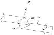
- FIG. 1is a view showing a state in which a hemostatic block is inserted into a joint cavity through an arthroscopy unit in an arthroscopic bleeding control apparatus according to an embodiment of the present invention.
- FIG. 2is a view showing a first embodiment of the hemostatic unit in the arthroscopic bleeding control apparatus according to an embodiment of the present invention, a view showing a wound state of the hemostatic block and a completed hemostatic unit.
- FIG 3is a view showing a second embodiment of the hemostasis unit in the arthroscopic bleeding control apparatus according to an embodiment of the present invention, a view showing a wound state of the hemostatic block and a completed hemostatic unit.
- FIG. 4is a view showing a third embodiment of the hemostasis unit in the arthroscopic bleeding control apparatus according to an embodiment of the present invention, a view showing a method of folding the hemostasis block.
- FIG. 5is a view showing a third embodiment of the hemostatic unit in the arthroscopic bleeding control apparatus according to an embodiment of the present invention, and completed according to the folded state of the hemostatic block according to the first modified example and the first modified example. It is a diagram showing a hemostatic unit.
- FIG. 6is a view showing a third embodiment of the hemostatic unit in the arthroscopic bleeding control apparatus according to an embodiment of the present invention, completed according to the folded state of the hemostatic block according to the second modified example and the second modified example. It is a diagram showing a hemostatic unit.
- FIG. 7is a view showing a third embodiment of the hemostatic unit in the arthroscopic bleeding control device according to an embodiment of the present invention, and completed according to the folded state of the hemostatic block according to the third modified example and the third modified example. It is a diagram showing a hemostatic unit.
- FIG. 8is a view showing a fourth embodiment of the hemostasis unit in the arthroscopic bleeding control apparatus according to an embodiment of the present invention, a view showing a method of folding the hemostasis block.
- FIG. 9is a view showing a fourth embodiment of the hemostasis unit in the arthroscopic bleeding control apparatus according to an embodiment of the present invention, a view showing a completed hemostasis unit.
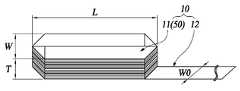
- FIG. 10is a view showing a fifth embodiment of the hemostatic unit in the arthroscopic bleeding control apparatus according to an embodiment of the present invention, a view showing a wound state of the hemostatic block and a completed hemostatic unit.
- FIG. 11is a view showing a sixth embodiment of the hemostatic unit in the arthroscopic bleeding control apparatus according to an embodiment of the present invention, (a) a method of folding a hemostatic block and (b) a folded state of the hemostatic block and (c) ) It is a diagram showing the completed hemostatic unit.
- FIG. 12is a view showing a seventh embodiment of the hemostasis unit in the arthroscopic bleeding control apparatus according to an embodiment of the present invention, a view showing a completed hemostasis unit.
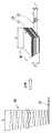
- FIG. 13is a cross-sectional view showing a combined state of a hemostasis unit and a block insertion unit in the arthroscopic bleeding control apparatus according to an embodiment of the present invention.
- FIG. 14is a cross-sectional view showing a state in which a hemostasis block is withdrawn from a block insertion unit in the arthroscopic bleeding control apparatus according to an embodiment of the present invention.
- the arthroscopic bleeding control apparatusis a device showing adsorption and hemostatic effects on bleeding occurring in the joint cavity 200 that can be exposed by the arthroscopy unit 100 As such, it may include a hemostatic unit 10, and may further include a block insertion unit 60.
- the hemostatic unit 10includes a hemostatic block 11 that passes through the arthroscopy unit 100 and is inserted into the joint cavity 200, and extends from the hemostatic block 11 so as to protrude to the outside through the arthroscopy unit 100. It includes a lead wire 12.
- the hemostatic block 11is compressed to a reference thickness (T) for being inserted into the joint cavity 200 at least in the thickness direction after winding or folding the hemostatic band 101 formed long in the longitudinal direction.
- the compressed hemostatic block 11is able to expand at least in the thickness direction by bleeding by adsorbing bleeding generated in the joint cavity 200, and the bleeding generated in the joint cavity 200 includes body fluids generated in the joint cavity 200. I can.
- the lead lead wire 12is made of a part of the hemostatic band 101 extending from the hemostatic block 11, so that the bleeding can be adsorbed even in the lead lead wire 12, and the bleeding adsorbed on the hemostatic band 101 is prevented. Thereby, a lubricating action is made between the arthroscopy unit 100 and the hemostatic strip 101, so that the withdrawal of the hemostatic strip 101 can be smoothly performed.
- the hemostatic block 11When the hemostatic block 11 pulls the lead wire 12 as the hemostatic block 11 adsorbs the bleeding from the joint cavity 200, the hemostatic strip 101 is unwound or the hemostatic strip 101 is released from the expanded hemostatic block 11 Accordingly, the hemostatic block 11 may be withdrawn from the joint cavity 200.
- the hemostatic unit 10may include a hemostatic block 11 and a lead lead 12 as shown in FIG. 2.
- the hemostatic block 11includes a winding shaft portion 20 forming a helical center from one end of the hemostatic band 101, and a hemostatic band 101 extending from the winding shaft portion 20. ) May include a spiral winding portion 30 formed as it is wound in a spiral shape.
- the take-up shaft part 20may be formed by partially winding the hemostatic strip 101 in a linear shape or by winding a portion of the hemostatic strip 101 or curling a portion of the hemostatic strip.
- the winding shaft portion 20 and the spiral winding portion 30are compressed to have a reference thickness T based on the length direction of the winding shaft portion 20, thereby completing the hemostatic block 11.
- the lead wire 12may extend from the free end of the hemostatic band 101 that is finally wound on the outer circumferential surface of the spiral winding unit 30.
- the hemostatic band 101is pulled out while the hemostatic block 11 rotates, so that foreign matter can be swept away from the joint cavity 200.
- the hemostasis block 11is shown to be formed in a cylindrical shape, but the present invention is not limited thereto, and may have an elliptical column shape.
- TW0 can be satisfied.
- Tmay satisfy substantially the same as W0.
- the diameter of the hemostatic block 11may satisfy 2R corresponding to the width of the joint cavity 200.
- Rdenotes the radius of the spiral winding portion 30 centered on the winding shaft portion 20.
- the hemostatic unit 10may include a hemostatic block 11 and a lead wire 12 as shown in FIG. 3.
- the hemostatic block 11includes a winding shaft portion 20 forming a helical center from one end of the hemostatic band 101, and a hemostatic band 101 extending from the winding shaft portion 20. ) May include a spiral winding portion 30 formed as it is wound in a spiral shape.
- the take-up shaft part 20may be formed by partially winding the hemostatic band 101 in a straight shape or by winding a part of the hemostatic band 101 or curling a part of the hemostatic band 101.
- the winding shaft portion 20 and the spiral winding portion 30are compressed to have a reference thickness T based on the length direction of the winding shaft portion 20, thereby completing the hemostatic block 11.
- the lead wire 12may extend from the free end of the take-up shaft portion 20.
- the hemostatic band 101is pulled out from the center of the hemostatic block 11, so that friction with the hemostatic band 101 in the joint cavity 200 is prevented, and the hemostatic block Due to the curling phenomenon of the hemostatic band 101 drawn from (11), friction with the hemostatic band 101 in the arthroscopy unit 100 can be minimized, thereby minimizing the friction.
- the hemostatic block 11is shown to be formed in a cylindrical shape, but the present invention is not limited thereto, and may have an elliptical cylindrical shape.
- TW0 can be satisfied.
- Tmay satisfy substantially the same as W0.
- the diameter of the hemostatic block 11may satisfy 2R corresponding to the width of the joint cavity 200.
- Rdenotes the radius of the spiral winding portion 30 centered on the winding shaft portion 20.
- the hemostatic unit 10may include a hemostatic block 11 and a lead wire 12 as shown in FIGS. 4 to 7.
- a forward folding part 401 and a reverse folding part 402are alternately arranged based on the length direction of the hemostatic band 101, and the forward folding part 401 and the reverse folding part
- the hemostatic band 101may include a foldable laminated portion 40 that is folded and stacked in zigzag.
- the forward folding part 401is a folding line for folding the hemostatic band 101 toward the lead line 12, and the reverse folding part 402 is spaced apart from the forward folding part 401 so that the hemostasis band 101 is folded in the forward direction. It can be made of a folding line for folding toward (401).
- the unit stacked partis formed from the lead line 12 as the unit stacked part is formed by the forward fold part 401 and the reverse fold part 402 adjacent to each other. It can be seen that they are sequentially stacked.
- the lengths of the unit-stacked partsmay be all the same, decrease sequentially along the stacking direction, or increase sequentially along the stacking direction.
- the length of the unit stacked portionmay be substantially the same along the stacking direction with respect to the lead lead line 12 as shown in FIG. 5.
- the length of the unit stacked portionmay gradually increase along the stacking direction based on the lead lead line 12 as shown in FIG. 6.
- the length of the unit stacked portionmay gradually decrease along the stacking method based on the lead lead line 12 as shown in FIG. 7.
- the foldable laminated portion 40may be compressed to have a reference thickness T based on the stacking direction of the hemostatic strip 101, thereby completing the hemostatic block 11.
- the lead wire 12is formed in the forward folding part 401 or the reverse folding part 402 formed at either end of the folding stacking part 40 based on the stacking direction of the hemostat strip 101. Can be extended. Then, the lead lead line 12 may extend from the lower end or the upper end of the hemostasis block 11.
- the hemostatic band 101is sequentially formed from the lower end or the upper end of the hemostatic block 11 inserted into the joint cavity 200 in response to the stacking of the hemostatic band 101. Since it is withdrawn, it is possible to reduce the friction between the hemostatic band 101 and the joint cavity 200 and the friction between the hemostatic band 101 and the arthroscopy unit 100.
- the hemostatic block 11may be formed in a rectangular column shape.
- the reference thickness Tis constant, and the length of the hemostatic block 11 can be adjusted according to the distance between the forward folding part 401 and the reverse folding part 402.
- the hemostatic unit 10may include a hemostatic block 11 and a lead wire 12 as shown in FIGS. 8 and 9.
- the hemostatic block 11is at the end of the first extension 501 to cross the first extension 501 and the first extension 501 forming a part of the hemostatic band 101.
- a fourth extension part 507 stacked on the end of the third extension part 505 so as to intersect with the third extension part 505 and the first extension part 501 and parallel to the second extension part 503,It may include a fold portion 50 that is sequentially stacked in the order of the fifth extension portion 5011 intersecting the fourth extension portion 507 and stacked on the first extension portion 501.
- the folding line connecting the first extension part 501 and the second extension part 503is referred to as the first forward inclined part 502, and the second extension part 503 and the third extension part 505 are The folded line by connecting is called a first reverse inclined part 504, and the fold line by connecting the third extension 505 and the fourth extension 507 is called a first forward inclined part 502, and the fourth The folding line connecting the extension part 507 and the fifth extension part 5011 is referred to as a second reverse inclined part 508, and when the hemostatic band 101 is additionally stacked on the second extension part 503, The line folded at the fifth extension part 5011 is referred to as a third forward inclined part 5021.
- the fold portion 50is compressed to have a reference thickness T based on the stacking direction of the hemostasis strip 101, thereby completing the hemostasis block 11.
- the lead wire 12may extend from the first extension part 501. Then, the lead lead line 12 may extend from the lower end or the upper end of the hemostasis block 11.
- the hemostatic band 101When pulling out the lead wire 12 according to the fourth embodiment, the hemostatic band 101 is rolled from the lower end or the upper end of the hemostatic block 11 inserted into the joint cavity 200 in response to the stacking of the hemostatic band 101 Since it is sequentially withdrawn, it is possible to reduce the friction between the hemostatic band 101 and the joint cavity 200 and the friction between the hemostatic band 101 and the arthroscopy unit 100.
- the hemostatic block 11may be formed in the shape of a hexagonal column or a rhombus column.
- the reference thickness Tis constant, and the length of the hemostatic block 11 can be adjusted according to the lengths of the first and third extensions 501 and 505.
- the hemostatic unit 10may include a hemostatic block 11 and a lead wire 12 as shown in FIG. 10.
- the hemostatic block 11includes a winding shaft portion 20 forming a helical center from one end of the hemostatic band 101, and a hemostatic band 101 extending from the winding shaft portion 20. It may include a helical winding portion 30 formed by winding in a helical shape at 20).
- the winding shaft portion 20is separated from the first shaft portion 21 forming a helical center from one end of the hemostatic band 101 and the first shaft portion 21 coaxially. It may include a second shaft portion 22 forming the center of the spiral from one end.
- Each of the first shaft part 21 and the second shaft part 22is provided with a part of the hemostatic band 101 in a straight shape, or by winding a part of the hemostatic band 101 or curling a part of the hemostatic band 101. Can be formed.
- the spiral winding portion 30includes a first winding portion 31 formed as the hemostatic band 101 extending from the first shaft portion 21 is wound around the first shaft portion 21 in a spiral shape. , Including a second winding portion 32 formed as the hemostasis band 101 stacked with the first winding portion 31 and extending from the second shaft portion 22 is wound in a spiral shape on the second shaft portion 22 can do.
- the spiral directions of the first and second winding portions 31 and 32are opposite, but the spiral directions may be the same.
- first shaft portion 21, the first winding portion 31, the second shaft portion 22, and the second winding portion 32is the length direction of the first shaft portion 21 or the length direction of the second shaft portion 22
- Treference thickness
- the lead wire 12includes a first lead wire 121 and a second shaft extending between the first winding portion 31 and the second winding portion 32 at the free end of the first shaft portion 21. It may include a second lead wire 122 extending between the first winding portion 31 and the second winding portion 32 at the free end of (22).
- the lead lead line 12further includes a connecting portion 123 integrally connecting the free end of the first lead line 121 and the free end of the second lead line 122, so that the lead lead line 12 has a ring shape. Can be displayed to facilitate the user's gripping.
- the hemostasis block 11is shown to be formed in a cylindrical shape, but the present invention is not limited thereto, and may have an elliptical column shape.
- TW0 can be satisfied.
- Tmay satisfy substantially the same as W0.
- the diameter of the hemostatic block 11may satisfy 2R corresponding to the width of the joint cavity 200.
- Rdenotes the radius of the spiral winding portion 30 centered on the winding shaft portion 20.
- the hemostatic unit 10has a winding shaft portion 20 forming a spiral center from one end of the hemostatic band 101, and a hemostatic band 101 extending from the winding shaft portion 20 as in the first embodiment. It may include a helical winding portion 30 formed as the winding shaft portion 20 is wound in a helical shape.
- the winding shaft portion 20is separated from the first shaft portion 21 forming a helical center from one end of the hemostatic band 101 and the first shaft portion 21 coaxially, and from one end of the hemostatic band 101 It may include a second shaft portion 22 forming the center of the spiral.
- Each of the first shaft part 21 and the second shaft part 22is provided with a part of the hemostatic band 101 in a straight shape, or by winding a part of the hemostatic band 101 or curling a part of the hemostatic band 101. Can be formed.
- the spiral winding portion 30includes a first winding portion 31 formed as the hemostatic band 101 extending from the first shaft portion 21 is wound in a spiral shape on the first shaft portion 21, and the first It may include a second winding portion 32 formed as the hemostatic band 101 stacked with the winding portion 31 and extending from the second shaft portion 22 is wound around the second shaft portion 22 in a spiral shape. .
- first shaft portion 21, the first winding portion 31, the second shaft portion 22, and the second winding portion 32is the length direction of the first shaft portion 21 or the length direction of the second shaft portion 22
- Treference thickness
- the lead wire 12is a first lead wire 121 extending from the free end of the hemostatic band 101 that is finally wound from the outer circumferential surface of the first winding part 31 and the outer circumferential surface of the second winding part 32 It may include a second lead wire 122 extending from the free end of the hemostatic band 101 that is finally wound in.
- the lead lead line 12further includes a connecting portion 123 integrally connecting the free end of the first lead line 121 and the free end of the second lead line 122, so that the lead lead line 12 has a ring shape. Can be displayed to facilitate the user's gripping.
- the hemostatic block 11When the withdrawal lead line 12 is pulled from the hemostatic unit 10, which is not shown, the hemostatic block 11 may be withdrawn while rotating.
- the first lead wire 121 and the second lead wire 122are adjacent to each other, and the hemostatic block 11 Can smoothly rotate.
- the hemostatic block 11may have a cylindrical shape or an elliptical column shape.
- the hemostatic unit 10may include a hemostatic block 11 and a lead wire 12 as shown in FIG. 11.
- the hemostatic block 11has a forward folding part 401 and a reverse folding part 402 alternately arranged based on the length direction of the hemostatic band 101, and the forward folding part 401 and the reverse folding Corresponding to the portion 402, the hemostatic band 101 may include a foldable laminated portion 40 that is folded and stacked in zigzag.
- the forward folding part 401is a folding line for folding the hemostatic band 101 toward the withdrawal lead line 12, and the reverse folding part 402 is spaced apart from the forward folding part 401 so that the hemostasis band 101 is folded in the forward direction. It can be made of a folding line for folding toward (401).
- the unit stacked partis formed from the lead wire 12 as the unit stacked part is formed by the forward fold part 401 and the reverse fold part 402 adjacent to each other. It can be seen that they are sequentially stacked.
- the lengths of the unit-stacked partsmay be all the same, decrease sequentially along the stacking direction, or increase sequentially along the stacking direction.
- the lead wire 12is a forward folding part 401 or a reverse folding part 402 formed at any one of both ends of the fold-stacking part 40 based on the stacking direction of the hemostatic band 101 as in the third embodiment. Can be extended from
- the lead line 12may include a first lead line 121 and a second lead line 122 disposed to face the first lead line 121.
- the lead lead line 12further includes a connecting portion 123 integrally connecting the free end of the first lead line 121 and the free end of the second lead line 122, so that the lead lead line 12 has a ring shape. Can be displayed to facilitate the user's gripping.
- the fold-laminated portion 40is a first folded and stacked zigzag by a forward folding portion 401 and a reverse folding portion 402 formed on the hemostat 101 extending from the first lead line 121.
- the second laminated part 42is folded and stacked in a zigzag by the laminated part 41 and the forward folding part 401 and the reverse folding part 402 formed on the hemostat 101 extending from the second lead wire 122 It may include.
- first stacked portion 41 and the second stacked portion 42are compressed to have a reference thickness T based on the stacking direction of the hemostatic strip 101, thereby completing the hemostatic block 11.
- the hemostasisis stopped from the middle part of the hemostatic block 11 between the first and second laminated parts 41 and 42. Since the band 101 is sequentially drawn out, it is possible to prevent friction with the hemostatic band 101 in the joint cavity 200 and reduce the friction between the hemostatic band 101 and the arthroscopy unit 100.
- the hemostatic block 11may be formed in a rectangular column shape.
- the reference thickness Tis constant, and the length of the hemostatic block 11 can be adjusted according to the distance between the forward folding part 401 and the reverse folding part 402.
- the hemostatic unit 10may include a hemostatic block 11 and a lead wire 12 as shown in FIG. 12.
- the hemostatic block 11includes a first extension part 501 forming a part of the hemostatic band 101, and the end of the first extension part 501 so as to intersect with the first extension part 501.
- itmay include a fold portion 50 that is sequentially stacked in the order of the fifth extension portion 5011 stacked on the first extension portion 501 by crossing the fourth extension portion 507.
- the lead lead wire 12may extend from the first extension part 501 as in the fourth embodiment.
- the lead line 12may include a first lead line 121 and a second lead line 122 disposed to face the first lead line 121.
- the lead lead line 12further includes a connecting portion 123 integrally connecting the free end of the first lead line 121 and the free end of the second lead line 122, so that the lead lead line 12 has a ring shape. Can be displayed to facilitate the user's gripping.
- the folding spiral portion 50is from the first extension portion 501 extending from the first lead line 121 to the second extension portion 503, the third extension portion 505, and the fourth extension portion ( 507) and the fifth extension portion 5011, the first spiral portion 51 sequentially stacked, and the second extension portion 503 and the second extension portion 503 from the first extension portion 501 extending from the second lead wire 122
- the third extension portion 505, the fourth extension portion 507, and the fifth extension portion 5011may include a second spiral portion 52 that is sequentially stacked.
- first spiral portion 51 and the second spiral portion 52are compressed to have a reference thickness T based on the stacking direction of the hemostatic strip 101, thereby completing the hemostatic block 11.
- the hemostasisis stopped from the middle part of the hemostatic block 11 between the first and second spiral parts 51 and 52. Since the band 101 is sequentially drawn while being rolled, it is possible to prevent friction between the hemostasis band 101 and the joint cavity 200, and reduce the friction between the hemostasis band 101 and the arthroscopy unit 100.
- the hemostatic block 11may be formed in the shape of a hexagonal column or a rhombus column.
- the reference thickness Tis constant, and the length of the hemostatic block 11 can be adjusted according to the lengths of the first and third extensions 501 and 505.
- the block insertion unit 60inserts the hemostatic block 11 into the joint cavity 200.
- the block insertion unit 60includes a block guide unit 61 forming a path through which the hemostatic block 11 is inserted into the joint cavity 200, and a block guide unit 61 by an external force. It may include a block transfer unit 62 for withdrawing the hemostatic block 11 in ).
- the hemostasis block 11is inserted into the block guide unit 61, and the lead wire 12 protrudes from one side of the block guide unit 61.
- the block guide unit 61may include a hollow sheath tube 611 into which the hemostatic block 11 is inserted, and a guide blade 613 that has elasticity and closes the other side of the sheath tube 611. At one side of the sheath tube 611, the block transfer unit 62 is fitted to be slidably moved.
- the guide blade 613is elastically deformed according to the slide movement of the hemostatic block 11 to open the other side of the sheath tube 611, so that the hemostatic block 11 can be pulled out from the other side of the sheath tube 611. .
- the block guide unit 61may further include a gripping blade 612 provided on one side of the sheath tube 611 for gripping by a user.
- the block transfer unit 62is fitted from one side of the block guide unit 61 so as not to interfere with the lead wire 12.
- the block transfer unit 62includes a transfer piston 621 that is slidably fitted to the sheath tube 611 of the block guide unit 61, and the transfer piston 621 protrudes to one side of the sheath tube 611. It may include an extended transmission rod 622 and a pusher 623 provided at the free end of the transmission rod 622 for pressing the user.
- the block transfer unit 62may further include a stopper 624 restricting the slide movement of the transfer piston 621.
- the stopper 624protrudes from the pusher 623 so as to be supported by one end of the sheath tube 611 or the gripping blade 612, and the transfer piston 621 is a hemostatic block to the other side of the block guide unit 61 When (11) is withdrawn, it is possible to prevent the transfer piston 621 from being withdrawn from the block guide unit (61).
- the delivery piston 621slides the hemostatic block 11 inserted into the sheath tube 611.
- the guide blade 613is opened with elasticity to open the other side of the sheath tube 611, and continues to the sheath tube. It is drawn out to the other side of 611 and inserted into the joint cavity 200.
- the transfer piston 621is supported by the guide blade 613 and is not drawn out to the other side of the sheath tube 611 .
- the drawing lead wirein the arthroscopy unit 100
- the drawing lead wirein the arthroscopy unit 100
- the transfer piston 621supports the guide wing 613, and the lead wire between the transfer piston 621 and the guide wing 613 Since (12) passes, it is possible to prevent the hemostatic band 101 from interfering with the block guide unit 61.
- the above-described arthroscopic bleeding control deviceexhibits a stable adsorption and hemostatic effect on bleeding occurring in the joint cavity 200, and the hemostatic block 11 that is expanded in accordance with the adsorption of the bleeding is removed from the joint cavity 200 without a separate tool. You can withdraw stably.
- the hemostatic unit 10is made of one hemostatic band 101, the hemostatic unit 10 can be integrated and the hemostatic block 11 can be easily manufactured.
- the hemostatic block 11can be formed in a cylindrical or elliptical shape, and the thickness of the hemostatic block 11 can be easily adjusted.
- the hemostatic block 11can be formed in a square column shape through the detailed configuration of the hemostatic unit 10, it is easy to adjust the length of the hemostatic block 11, and according to the release of the hemostatic block 11 folding
- the hemostatic band 101is drawn flat from the joint cavity 200 or the arthroscopy unit 100, and friction with the hemostatic band 101 can be minimized.
- the hemostatic block 11can be formed in a hexagonal column or rhombus column shape, and it is easy to adjust the length of the hemostatic block 11, and the hemostatic block 11 is folded. According to the release, the hemostatic band 101 is drawn out in a rolled form, and a friction phenomenon with the hemostatic band 101 in the joint cavity 200 or the arthroscopy unit 100 can be minimized.
- the hemostatic band ( 101) and frictioncan be minimized.
- the size of the hemostatic block 11 in the joint cavity 200may be adjusted through the relationship between the width of the lead lead line 12 and the width of the foldable layer 40.
- hemostatic block 11may be stably inserted into the joint cavity 200 through the block insertion unit 60.
- hemostatic block 11 inserted into the block guide unit 61can be stably positioned in the joint cavity 200 through the detailed configuration of the block insertion unit 60.
- the arthroscopy unit 100prevents friction of the block guide unit 61,
- the hemostatic block 11is stably withdrawn from the other side of the block guide unit 61, and when the block guide unit 61 is withdrawn, the guide blade 613 can be prevented from being rubbed against the arthroscopy unit 100. have.
- the present inventionrelates to an arthroscopic bleeding control device, which exhibits a stable adsorption and hemostatic effect on bleeding occurring in the joint cavity in performing arthroscopic procedures, and a hemostatic block that has been expanded according to the adsorption of the bleeding is removed without a separate tool. You can stably withdraw from.
Landscapes
- Health & Medical Sciences (AREA)
- Life Sciences & Earth Sciences (AREA)
- General Health & Medical Sciences (AREA)
- Public Health (AREA)
- Engineering & Computer Science (AREA)
- Biomedical Technology (AREA)
- Heart & Thoracic Surgery (AREA)
- Animal Behavior & Ethology (AREA)
- Veterinary Medicine (AREA)
- Vascular Medicine (AREA)
- Surgery (AREA)
- Epidemiology (AREA)
- Nuclear Medicine, Radiotherapy & Molecular Imaging (AREA)
- Medical Informatics (AREA)
- Molecular Biology (AREA)
- Reproductive Health (AREA)
- Orthopedic Medicine & Surgery (AREA)
- Surgical Instruments (AREA)
Abstract
Description
Translated fromKorean본 발명은 관절경 출혈 컨트롤장치에 관한 것으로, 보다 구체적으로는 관절강에서 발생되는 출혈에 대해 안정된 흡착 및 지혈 효과를 나타내고, 출혈의 흡착에 따라 팽창된 지혈블럭을 별도의 도구없이도 관절강으로부터 안정되게 인출할 수 있는 관절경 출혈 컨트롤장치에 관한 것이다.The present invention relates to an arthroscopic bleeding control device, and more specifically, exhibits a stable adsorption and hemostatic effect on bleeding occurring in the joint cavity, and stably withdraws the hemostatic block expanded from the joint cavity without a separate tool due to the adsorption of the bleed It relates to a device that can control arthroscopic bleeding.
일반적으로, 관절경은 일종의 내시경으로써, 관절강 내의 변화를 직접 관찰하거나 사진으로 촬영할 수 있다.In general, the arthroscopy is a type of endoscope, and changes in the joint cavity can be directly observed or photographed.
이러한 관절경은 관절을 절개하지 않고 피부조직에 형성된 소구경의 관절경 검사부를 통하여 관절 내의 병변을 직접 보면서 정확한 진단을 할 수 있고, 관절 내의 모든 종류의 수술을 시행가능하게 해준다.Such an arthroscopy enables accurate diagnosis by directly viewing the lesions in the joints through a small-diameter arthroscopy unit formed in the skin tissue without cutting the joints, and makes it possible to perform all types of surgery within the joints.
예를 들어, 관절경을 이용하여 가능한 슬관절 수술로는 유리체(loose body) 제거술, 반달연골 적출술(meniscectomy) 혹은 봉합술(meniscal repair), 윤활막 절제술(synovectomy), 전방 또는 후방 십자인대 재건술(reconstruction of cruciate ligament) 등을 예로 들 수 있다.For example, arthroscopy can be used for knee surgery including loose body removal, meniscectomy or meniscal repair, synovectomy, reconstruction of cruciate anterior or posterior cruciate. ligament) and the like.
관절경은 관절을 절개하지 않기 때문에 수술 후 통증이 적고, 관절 운동의 빠른 회복과 수술 합병증이 적으며, 치료비가 절감되는 등의 많은 장점들로 인해 어깨, 팔꿈치, 손, 고관절, 무릎, 발, 척추 등 모든 관절에 적용할 수 있고, 특히, 무릎 관절(슬관절)에 이용률이 높다.Because arthroscopy does not incise joints, it has many advantages such as less pain after surgery, quick recovery of joint movement and less complications from surgery, and reduced treatment costs, such as shoulders, elbows, hands, hips, knees, feet, and spine. It can be applied to all joints, especially the knee joint (knee joint).
이때, 관절경 시술 중 혹은 시술이 종료되는 시점에 관절강에서 출혈이 발생할 경우 지혈을 필요로 하지만, 소구경의 관절경 검사부로 인해 지혈에 어려움을 겪고 있다.At this time, when bleeding occurs in the joint cavity during or at the end of the arthroscopic procedure, hemostasis is required, but due to the small-diameter arthroscopy section, hemostasis is difficult.
관련선행기술로는 대한민국 공개특허공보 제2019-0091771호(발명의 명칭 : 내시경용 지혈클립, 2019. 08. 07. 공개)가 있다.As a related prior art, there is Korean Laid-Open Patent Publication No. 2019-0091771 (name of the invention: hemostatic clip for endoscopy, published on August 07, 2019).
본 발명의 목적은 종래의 문제점을 해결하기 위한 것으로서, 관절강에서 발생되는 출혈에 대해 안정된 흡착 및 지혈 효과를 나타내고, 출혈의 흡착에 따라 팽창된 지혈블럭을 별도의 도구없이도 관절강으로부터 안정되게 인출할 수 있는 관절경 출혈 컨트롤장치를 제공함에 있다.An object of the present invention is to solve the conventional problem, it shows a stable adsorption and hemostatic effect on bleeding occurring in the joint cavity, and the hemostatic block that has been expanded by the adsorption of the bleeding can be stably withdrawn from the joint cavity without a separate tool. It is to provide an arthroscopic bleeding control device.
상술한 본 발명의 목적을 달성하기 위한 바람직한 실시예에 따르면, 본 발명에 따른 관절경 출혈 컨트롤장치는 관절경 검사부에 의해 노출 가능한 관절강에서 발생되는 출혈에 대해 흡착 및 지혈 효과를 나타내는 관절경 출혈 컨트롤장치이고, 상기 관절경 검사부를 통과하여 상기 관절강에 삽입되는 지혈블럭과, 상기 관절경 검사부를 통과하여 외부로 돌출되도록 상기 지혈블럭에서 연장되는 인출리드선을 포함하는 지혈유닛;을 포함하며, 상기 지혈블럭은, 길이 방향으로 길게 형성되는 지혈띠를 감거나 접은 다음, 적어도 두께 방향에 대하여 상기 관절강에 삽입되기 위한 기준두께로 압축됨에 따라 상기 관절강에서 발생되는 출혈에 의해 적어도 두께 방향으로 팽창 가능하고, 상기 인출리드선을 잡아당기면, 팽창된 상기 지혈블럭에서 상기 지혈띠의 감김 해제 또는 상기 지혈띠의 접힘 해제에 따라 상기 지혈블럭이 상기 관절강에서 인출된다.According to a preferred embodiment for achieving the object of the present invention described above, the arthroscopic bleeding control apparatus according to the present invention is an arthroscopic bleeding control that exhibits adsorption and hemostatic effects for bleeding occurring in the joint cavity exposed by the arthroscopy unit. A hemostasis unit, comprising: a hemostasis block that passes through the arthroscopy unit and is inserted into the joint cavity, and a pull-out lead wire extending from the hemostatic block so as to protrude to the outside through the arthroscopy unit. The block is expandable in the thickness direction at least by bleeding generated in the joint cavity as the block is compressed to a reference thickness for insertion into the joint cavity in at least a thickness direction after winding or folding a hemostatic band formed long in the longitudinal direction, When the withdrawal lead wire is pulled, the hemostatic block is withdrawn from the joint cavity according to the release of winding of the hemostatic band or the folding of the hemostatic band from the expanded hemostatic block.
여기서, 상기 인출리드선은, 상기 지혈블럭에서 연장되는 상기 지혈띠의 일부로 이루어진다.Here, the withdrawal lead wire is made of a part of the hemostatic band extending from the hemostatic block.
여기서, 상기 지혈블럭은, 지혈띠의 일단부로부터 나선 중심을 형성하는 권취축부; 및 상기 권취축부에서 연장되는 지혈띠가 상기 권취축부에 나선 형상으로 권취됨에 따라 형성되는 나선권취부;를 포함하고, 상기 인출리드선은, 상기 나선권취부의 외주면에서 마지막으로 권취되는 지혈띠의 자유단부에서 연장되며, 상기 권취축부와 상기 나선권취부는, 상기 권취축부의 길이 방향을 기준으로 상기 기준두께가 되도록 압축된다.Here, the hemostasis block, a winding shaft portion forming a helical center from one end of the hemostasis band; And a helical winding portion formed as the hemostat band extending from the winding shaft portion is wound in a spiral shape on the winding shaft portion, wherein the lead wire is free of the hemostasis band finally wound on the outer circumferential surface of the spiral winding portion. It extends from an end portion, and the winding shaft portion and the spiral winding portion are compressed to have the reference thickness based on the length direction of the winding shaft portion.
여기서, 상기 권취축부는, 지혈띠의 일단부로부터 나선 중심을 형성하는 제1축부; 및 동축에서 상기 제1축부와 분리되고, 지혈띠의 일단부로부터 나선 중심을 형성하는 제2축부;를 포함하고, 상기 나선권취부는, 상기 제1축부에서 연장되는 지혈띠가 상기 제1축부에 나선 형상으로 권취됨에 따라 형성되는 제1권취부; 및 상기 제1권취부와 적층되고, 상기 제2축부에서 연장되는 지혈띠가 상기 제2축부에 나선 형상으로 권취됨에 따라 형성되는 제2권취부;를 포함하며, 상기 인출리드선은, 상기 제1권취부의 외주면에서 마지막으로 권취되는 지혈띠의 자유단부에서 연장되는 제1리드선; 및 상기 제2권취부의 외주면에서 마지막으로 권취되는 지혈띠의 자유단부에서 연장되는 제2리드선;을 포함한다.Here, the winding shaft portion, a first shaft portion forming a helical center from one end of the hemostasis band; And a second shaft part coaxially separated from the first shaft part and forming a helical center from one end of the hemostatic band, wherein the helical winding part includes a hemostat band extending from the first shaft part to the first shaft part. A first winding portion formed by winding in a spiral shape; And a second winding portion stacked with the first winding portion and formed by a hemostatic band extending from the second shaft portion being wound in a spiral shape on the second shaft portion, wherein the lead wire includes the first A first lead wire extending from the free end of the hemostasis band that is finally wound on the outer circumferential surface of the winding unit; And a second lead wire extending from the free end of the hemostasis band that is finally wound on the outer circumferential surface of the second winding unit.
여기서, 상기 지혈블럭은, 지혈띠의 일단부로부터 나선 중심을 형성하는 권취축부; 및 상기 권취축부에서 연장되는 지혈띠가 상기 권취축부에 나선 형상으로 권취됨에 따라 형성되는 나선권취부;를 포함하고, 상기 인출리드선은, 상기 권취축부의 자유단부에서 연장되며, 상기 권취축부와 상기 나선권취부는, 상기 권취축부의 길이 방향을 기준으로 상기 기준두께가 되도록 압축된다.Here, the hemostasis block, a winding shaft portion forming a helical center from one end of the hemostasis band; And a helical winding portion formed as the hemostat band extending from the winding shaft portion is wound in a spiral shape on the winding shaft portion, wherein the lead wire extends from the free end portion of the winding shaft portion, and the winding shaft portion and the The spiral winding portion is compressed to have the reference thickness based on the length direction of the winding shaft portion.
여기서, 상기 권취축부는, 지혈띠의 일단부로부터 나선 중심을 형성하는 제1축부; 및 동축에서 상기 제1축부와 분리되고, 지혈띠의 일단부로부터 나선 중심을 형성하는 제2축부;를 포함하고, 상기 나선권취부는, 상기 제1축부에서 연장되는 지혈띠가 상기 제1축부에 나선 형상으로 권취됨에 따라 형성되는 제1권취부; 및 상기 제1권취부와 적층되고, 상기 제2축부에서 연장되는 지혈띠가 상기 제2축부에 나선 형상으로 권취됨에 따라 형성되는 제2권취부;를 포함하며, 상기 인출리드선은, 상기 제1축부의 자유단부에서 상기 제1권취부와 상기 제2권취부 사이로 연장되는 제1리드선; 및 상기 제2축부의 자유단부에서 상기 제1권취부와 상기 제2권취부 사이로 연장되는 제2리드선;을 포함한다.Here, the winding shaft portion, a first shaft portion forming a helical center from one end of the hemostasis band; And a second shaft part coaxially separated from the first shaft part and forming a helical center from one end of the hemostatic band, wherein the helical winding part includes a hemostat band extending from the first shaft part to the first shaft part. A first winding portion formed by winding in a spiral shape; And a second winding portion stacked with the first winding portion and formed by a hemostatic band extending from the second shaft portion being wound in a spiral shape on the second shaft portion, wherein the lead wire includes the first A first lead wire extending between the first winding portion and the second winding portion at the free end of the shaft portion; And a second lead wire extending between the first winding portion and the second winding portion from the free end of the second shaft portion.
여기서, 상기 지혈블럭은, 지혈띠의 길이 방향을 기준으로 지혈띠를 상기 인출리드선 쪽으로 접기 위한 정방향접이부와, 지혈띠를 상기 정방향접이부 쪽으로 접기 위한 역방향접이부가 교대로 배치되고 지혈띠가 지그재그로 접혀서 적층되는 접이적층부;를 포함하고, 상기 인출리드선은, 지혈띠의 적층 방향을 기준으로 상기 접이적층부의 양단부 중 어느 하나에 형성되는 상기 정방향접이부 또는 상기 역방향접이부에서 연장되며, 상기 접이적층부는, 지혈띠의 적층 방향을 기준으로 상기 기준두께가 되도록 압축된다.Here, the hemostatic block is alternately arranged with a forward folding part for folding the hemostatic band toward the withdrawal lead line and a reverse folding part for folding the hemostatic band toward the forward folding part based on the length direction of the hemostatic band, and the hemostatic band is zigzag. Including; the lead wire is folded and stacked by folding; extends from the forward folding portion or the reverse folding portion formed on either end of the folding stacked portion based on the stacking direction of the hemostat, and the The folding laminated portion is compressed to have the reference thickness based on the stacking direction of the hemostatic band.
여기서, 상기 인출리드선은, 제1리드선; 및 상기 제1리드선과 마주보도록 배치되는 제2리드선;을 포함하고, 상기 접이적층부는, 상기 제1리드선에서 연장되는 지혈띠에 형성된 정방향접이부와 역방향접이부에 의해 지그재그로 접혀서 적층되는 제1적층부; 및 상기 제2리드선에서 연장되는 지혈띠에 형성된 정방향접이부와 역방향접이부에 의해 지그재그로 접혀서 적층되는 제2적층부;를 포함한다.Here, the lead lead wire may include a first lead wire; And a second lead line disposed to face the first lead line, wherein the foldable laminated portion is a first laminated layer folded in zigzag by a forward fold and a reverse fold formed on a hemostatic band extending from the first lead line. part; And a second laminated portion folded and stacked in a zigzag by a forward fold and a reverse fold formed on the hemostasis band extending from the second lead wire.
여기서, 상기 접이적층부에서 상기 지혈띠를 지그재그로 접을 때 형성되는 단위적층부의 길이는, 모두 동일하거나, 적층 방향을 따라 순차적으로 작아지거나, 적층 방향을 따라 순차적으로 커진다.Here, the lengths of the unit laminates formed when the hemostasis band is folded in zigzag in the foldable laminated part are all the same, decrease sequentially along the stacking direction, or increase sequentially along the stacking direction.
여기서, 상기 인출리드선의 폭을 W0라 하고, 상기 접이적층부의 폭을 W라 하면, W/2 <= W0 <= W 를 만족한다.Here, if the width of the lead wire is W0 and the width of the foldable layer is W, W/2 <= W0 <= W is satisfied.
여기서, 상기 지혈블럭은, 상기 지혈띠의 일부를 형성하는 제1연장부와, 상기 제1연장부와 교차되도록 상기 제1연장부의 단부에 적층되는 제2연장부와, 상기 제2연장부와 교차되고 제1연장부와 평형하도록 상기 제2연장부의 단부에 적층되는 제3연장부와, 상기 제3연장부 및 상기 제1연장부와 교차되고 상기 제2연장부와 평행하도록 상기 제3연장부의 단부에 적층되는 제4연장부와, 상기 제4연장부와 교차되어 상기 제1연장부에 적층되는 제5연장부 순으로 순차 적층되는 접이나선부;를 포함하고, 상기 인출리드선은, 상기 제1연장부에서 연장되며, 상기 접이나선부는, 지혈띠의 적층 방향을 기준으로 상기 기준두께가 되도록 압축된다.Here, the hemostatic block comprises: a first extension part forming a part of the hemostatic band, a second extension part stacked on an end of the first extension part so as to cross the first extension part, the second extension part, and The third extension is intersected and stacked on the end of the second extension so as to be parallel with the first extension, and the third extension is intersected with the third extension and the first extension and is parallel to the second extension. A fourth extension portion stacked at an end of the negative portion, and a fold spiral portion sequentially stacked in order of a fifth extension portion stacked on the first extension portion by intersecting with the fourth extension portion, wherein the lead wire includes: It extends from the first extension portion, and the foldable portion is compressed to have the reference thickness based on the stacking direction of the hemostasis band.
여기서, 상기 인출리드선은, 제1리드선; 및 상기 제1리드선과 마주보도록 배치되는 제2리드선;을 포함하고, 상기 접이나선부는, 상기 제1리드선에서 연장되는 제1연장부부터 제2연장부와 제3연장부 순으로 순차 적층되는 제1나선부; 및 상기 제2리드선에서 연장되는 제1연장부로부터 제2연장부와 제3연장부 순으로 순차 적층되는 제2나선부;를 포함한다.Here, the lead lead wire may include a first lead wire; And a second lead line disposed to face the first lead line, wherein the foldable spiral portion comprises: a first extension portion extending from the first lead line, a second extension portion, and a third extension portion sequentially stacked. 1 helix part; And a second spiral portion sequentially stacked from the first extension portion extending from the second lead wire in the order of the second extension portion and the third extension portion.
여기서, 상기 인출리드선의 폭을 W0라 하고, 상기 접이적층부의 폭을 W라 하면, W=W0/2 를 만족한다.Here, if the width of the lead wire is W0 and the width of the foldable layer is W, W=W0/2 is satisfied.
본 발명에 따른 관절경 출혈 컨트롤장치는 상기 지혈블럭을 상기 관절강에 삽입하는 블럭삽입유닛;을 더 포함한다.The arthroscopic bleeding control apparatus according to the present invention further includes a block insertion unit for inserting the hemostatic block into the joint cavity.
여기서, 상기 블럭삽입유닛은, 상기 지혈블럭이 상기 관절강에 삽입되는 경로를 형성하되, 상기 지혈블럭이 삽입되는 블럭가이드유닛; 및 상기 블럭가이드유닛의 일측에 끼움 결합되고, 외력에 의해 상기 블럭가이드유닛의 타측으로 상기 지혈블럭을 인출시키는 블럭전달유닛;을 포함한다.Here, the block insertion unit, a block guide unit that forms a path through which the hemostatic block is inserted into the joint cavity, and into which the hemostatic block is inserted; And a block transfer unit that is fitted to one side of the block guide unit and pulls the hemostatic block to the other side of the block guide unit by an external force.
여기서, 상기 블럭가이드유닛은, 상기 지혈블럭이 삽입되되, 일측에는 상기 블럭전달유닛이 슬라이드 이동 가능하게 끼움 결합되는 중공의 쉬스튜브; 및 탄성을 가지고 상기 쉬스튜브의 타측을 폐쇄하는 가이드날개;를 포함하고, 상기 가이드날개는, 상기 지혈블럭의 슬라이드 이동에 따라 탄성 변형에 의해 상기 쉬스튜브의 타측을 개방한다.Here, the block guide unit, the hemostasis block is inserted, the block transfer unit is inserted into a hollow sheath tube to be movably inserted into one side; And a guide blade having elasticity and closing the other side of the sheath tube, wherein the guide blade opens the other side of the sheath tube by elastic deformation according to the slide movement of the hemostasis block.
본 발명에 따른 관절경 출혈 컨트롤장치에 따르면, 관절강에서 발생되는 출혈에 대해 안정된 흡착 및 지혈 효과를 나타내고, 출혈의 흡착에 따라 팽창된 지혈블럭을 별도의 도구없이도 관절강으로부터 안정되게 인출할 수 있다.According to the arthroscopic bleeding control apparatus according to the present invention, it exhibits a stable adsorption and hemostatic effect on bleeding occurring in the joint cavity, and the hemostatic block that has been expanded according to the adsorption of the bleeding can be stably withdrawn from the joint cavity without a separate tool.
또한, 본 발명은 지혈유닛이 하나의 지혈띠로 이루어짐으로써, 지혈유닛을 일체화시키고, 지혈블럭을 간편하게 제조할 수 있다.In addition, according to the present invention, since the hemostatic unit consists of one hemostatic band, the hemostatic unit is integrated and the hemostatic block can be conveniently manufactured.
또한, 본 발명은 지혈유닛의 세부 구성을 통해 지혈블럭을 원기둥 형상 또는 타원기둥 형상으로 형성할 수 있고, 지혈블럭의 두께 조절을 간편하게 할 수 있다.In addition, in the present invention, the hemostatic block can be formed in a cylindrical or elliptical shape through the detailed configuration of the hemostatic unit, and the thickness of the hemostatic block can be easily adjusted.
또한, 본 발명은 지혈유닛의 세부 구성을 통해 지혈블럭의 감김 해제에 따라 관절강 또는 관절경 검사부에서 지혈띠와의 쓸림 현상을 최소화시킬 수 있다.In addition, the present invention can minimize the friction with the hemostatic band in the joint cavity or arthroscopy unit according to the release of the hemostatic block through the detailed configuration of the hemostatic unit.
또한, 본 발명은 지혈유닛의 세부 구성을 통해 지혈블럭을 사각 기둥 형상으로 형성할 수 있고, 지혈블럭의 길이 조절을 용이하게 하며, 지혈블럭의 접힘 해제에 따라 관절강 또는 관절경 검사부에서 지혈띠가 납작하게 인출되고, 지혈띠와의 쓸림 현상을 최소화시킬 수 있다.In addition, the present invention can form a hemostatic block in a square column shape through the detailed configuration of the hemostatic unit, facilitates the adjustment of the length of the hemostatic block, and releases the hemostatic band in the joint cavity or arthroscopy unit according to the release of the hemostatic block. It is drawn out flat, and it can minimize friction with the hemostasis band.
또한, 본 발명은 지혈유닛의 세부 구성을 통해 지혈블럭을 육각형 기둥 또는 마름모 기둥 형상으로 형성할 수 있고, 지혈블럭의 길이 조절을 용이하게 하며, 지혈블럭의 접힘 해제에 따라 지혈띠가 말린 형태로 인출되고, 관절강 또는 관절경 검사부에서 지혈띠와의 쓸림 현상을 최소화시킬 수 있다.In addition, the present invention can form the hemostatic block in the shape of a hexagonal column or rhombus column through the detailed configuration of the hemostatic unit, facilitates adjustment of the length of the hemostatic block, and the hemostatic band is rolled according to the release of the hemostatic block. It is pulled out, and it is possible to minimize friction with the hemostatic band in the joint cavity or arthroscopy section.
또한, 본 발명은 지혈유닛에서 지혈블럭을 양분하고 양분된 지혈블럭 사이에서 지혈띠가 인출되도록 함으로써, 관절강 또는 관절경 검사부에서 지혈띠와의 쓸림 현상을 최소화시킬 수 있다.In addition, according to the present invention, by dividing the hemostatic block in the hemostatic unit and allowing the hemostatic band to be withdrawn between the divided hemostatic blocks, it is possible to minimize the friction between the hemostatic band in the joint cavity or arthroscopy unit.
또한, 본 발명은 인출리드선의 폭과 접이적층부의 폭 사이의 관계를 통해 관절강에서 지혈블럭의 크기를 조절할 수 있다.In addition, the present invention can adjust the size of the hemostatic block in the joint cavity through the relationship between the width of the lead wire and the width of the foldable layer.
또한, 본 발명은 블럭삽입유닛을 통해 지혈블럭을 관절강에 안정되게 삽입할 수 있다.In addition, the present invention can stably insert the hemostatic block into the joint cavity through the block insertion unit.
또한, 본 발명은 블럭삽입유닛의 세부 구성을 통해 블럭가이드유닛에 삽입된 지혈블럭을 관절강에 안정되게 정위치시킬 수 있다.In addition, the present invention can stably position the hemostatic block inserted into the block guide unit in the joint cavity through the detailed configuration of the block insertion unit.
또한, 본 발명은 블럭가이드유닛의 세부 구성을 통해 블럭가이드유닛이 관절경 검사부에 삽입될 때, 관절경 검사부에서 블럭가이드유닛의 쓸림을 방지하고, 블럭가이드유닛의 타측에서 지혈블럭이 안정되게 인출되며, 블럭가이드유닛을 인출할 때, 가이드날개가 관절경 검사부에 쓸리는 것을 방지할 수 있다.In addition, the present invention prevents friction of the block guide unit in the arthroscopy unit when the block guide unit is inserted into the arthroscopy unit through the detailed configuration of the block guide unit, and the hemostatic block is stably withdrawn from the other side of the block guide unit. When the block guide unit is withdrawn, it is possible to prevent the guide blades from being rubbed against the arthroscopy unit.
도 1은 본 발명의 일 실시예에 따른 관절경 출혈 컨트롤장치에서 지혈블럭이 관절경 검사부를 통하여 관절강에 삽입된 상태를 도시한 도면이다.1 is a view showing a state in which a hemostatic block is inserted into a joint cavity through an arthroscopy unit in an arthroscopic bleeding control apparatus according to an embodiment of the present invention.
도 2는 본 발명의 일 실시예에 따른 관절경 출혈 컨트롤장치에서 지혈유닛의 제1실시예를 도시한 도면으로, 지혈블럭의 감긴 상태와 완성된 지혈유닛을 나타내는 도면이다.2 is a view showing a first embodiment of the hemostatic unit in the arthroscopic bleeding control apparatus according to an embodiment of the present invention, a view showing a wound state of the hemostatic block and a completed hemostatic unit.
도 3은 본 발명의 일 실시예에 따른 관절경 출혈 컨트롤장치에서 지혈유닛의 제2실시예를 도시한 도면으로, 지혈블럭의 감긴 상태와 완성된 지혈유닛을 나타내는 도면이다.3 is a view showing a second embodiment of the hemostasis unit in the arthroscopic bleeding control apparatus according to an embodiment of the present invention, a view showing a wound state of the hemostatic block and a completed hemostatic unit.
도 4는 본 발명의 일 실시예에 따른 관절경 출혈 컨트롤장치에서 지혈유닛의 제3실시예를 도시한 도면으로, 지혈블럭의 접는 방법을 나타내는 도면이다.4 is a view showing a third embodiment of the hemostasis unit in the arthroscopic bleeding control apparatus according to an embodiment of the present invention, a view showing a method of folding the hemostasis block.
도 5는 본 발명의 일 실시예에 따른 관절경 출혈 컨트롤장치에서 지혈유닛의 제3실시예를 도시한 도면으로, 제1변형예에 따른 지혈블럭의 접힌 상태와 제1변형예에 따라 완성된 지혈유닛을 나타내는 도면이다.5 is a view showing a third embodiment of the hemostatic unit in the arthroscopic bleeding control apparatus according to an embodiment of the present invention, and completed according to the folded state of the hemostatic block according to the first modified example and the first modified example. It is a diagram showing a hemostatic unit.
도 6은 본 발명의 일 실시예에 따른 관절경 출혈 컨트롤장치에서 지혈유닛의 제3실시예를 도시한 도면으로, 제2변형예에 따른 지혈블럭의 접힌 상태와 제2변형예에 따라 완성된 지혈유닛을 나타내는 도면이다.6 is a view showing a third embodiment of the hemostatic unit in the arthroscopic bleeding control apparatus according to an embodiment of the present invention, completed according to the folded state of the hemostatic block according to the second modified example and the second modified example. It is a diagram showing a hemostatic unit.
도 7은 본 발명의 일 실시예에 따른 관절경 출혈 컨트롤장치에서 지혈유닛의 제3실시예를 도시한 도면으로, 제3변형예에 따른 지혈블럭의 접힌 상태와 제3변형예에 따라 완성된 지혈유닛을 나타내는 도면이다.7 is a view showing a third embodiment of the hemostatic unit in the arthroscopic bleeding control device according to an embodiment of the present invention, and completed according to the folded state of the hemostatic block according to the third modified example and the third modified example. It is a diagram showing a hemostatic unit.
도 8은 본 발명의 일 실시예에 따른 관절경 출혈 컨트롤장치에서 지혈유닛의 제4실시예를 도시한 도면으로, 지혈블럭의 접는 방법을 나타내는 도면이다.8 is a view showing a fourth embodiment of the hemostasis unit in the arthroscopic bleeding control apparatus according to an embodiment of the present invention, a view showing a method of folding the hemostasis block.
도 9는 본 발명의 일 실시예에 따른 관절경 출혈 컨트롤장치에서 지혈유닛의 제4실시예를 도시한 도면으로, 완성된 지혈유닛을 나타내는 도면이다.9 is a view showing a fourth embodiment of the hemostasis unit in the arthroscopic bleeding control apparatus according to an embodiment of the present invention, a view showing a completed hemostasis unit.
도 10은 본 발명의 일 실시예에 따른 관절경 출혈 컨트롤장치에서 지혈유닛의 제5실시예를 도시한 도면으로, 지혈블럭의 감긴 상태와 완성된 지혈유닛을 나타내는 도면이다.10 is a view showing a fifth embodiment of the hemostatic unit in the arthroscopic bleeding control apparatus according to an embodiment of the present invention, a view showing a wound state of the hemostatic block and a completed hemostatic unit.
도 11은 본 발명의 일 실시예에 따른 관절경 출혈 컨트롤장치에서 지혈유닛의 제6실시예를 도시한 도면으로, (a) 지혈블럭의 접는 방법과 (b) 지혈블럭의 접힌 상태와 (c) 완성된 지혈유닛을 나타내는 도면이다.11 is a view showing a sixth embodiment of the hemostatic unit in the arthroscopic bleeding control apparatus according to an embodiment of the present invention, (a) a method of folding a hemostatic block and (b) a folded state of the hemostatic block and (c) ) It is a diagram showing the completed hemostatic unit.
도 12는 본 발명의 일 실시예에 따른 관절경 출혈 컨트롤장치에서 지혈유닛의 제7실시예를 도시한 도면으로, 완성된 지혈유닛을 나타내는 도면이다.12 is a view showing a seventh embodiment of the hemostasis unit in the arthroscopic bleeding control apparatus according to an embodiment of the present invention, a view showing a completed hemostasis unit.
도 13은 본 발명의 일 실시예에 따른 관절경 출혈 컨트롤장치에서 지혈유닛과 블럭삽입유닛의 결합 상태를 도시한 단면도이다.13 is a cross-sectional view showing a combined state of a hemostasis unit and a block insertion unit in the arthroscopic bleeding control apparatus according to an embodiment of the present invention.
도 14는 본 발명의 일 실시예에 따른 관절경 출혈 컨트롤장치에서 블럭삽입유닛에서 지혈블럭이 인출된 상태를 도시한 단면도이다.14 is a cross-sectional view showing a state in which a hemostasis block is withdrawn from a block insertion unit in the arthroscopic bleeding control apparatus according to an embodiment of the present invention.
이하, 첨부된 도면들을 참조하여 본 발명에 따른 관절경 출혈 컨트롤장치의 일 실시예를 설명한다. 이때, 본 발명은 실시예에 의해 제한되거나 한정되는 것은 아니다. 또한, 본 발명을 설명함에 있어서, 공지된 기능 혹은 구성에 대해 구체적인 설명은 본 발명의 요지를 명확하게 하기 위해 생략될 수 있다.Hereinafter, an embodiment of an arthroscopic bleeding control apparatus according to the present invention will be described with reference to the accompanying drawings. At this time, the present invention is not limited or limited by the examples. In addition, in describing the present invention, detailed descriptions of known functions or configurations may be omitted to clarify the gist of the present invention.
도 1 내지 도 14를 참조하면, 본 발명의 일 실시예에 따른 관절경 출혈 컨트롤장치는 관절경 검사부(100)에 의해 노출 가능한 관절강(200)에서 발생되는 출혈에 대해 흡착 및 지혈 효과를 나타내는 장치로써, 지혈유닛(10)을 포함하고, 블럭삽입유닛(60)을 더 포함할 수 있다.1 to 14, the arthroscopic bleeding control apparatus according to an embodiment of the present invention is a device showing adsorption and hemostatic effects on bleeding occurring in the
지혈유닛(10)은 관절경 검사부(100)를 통과하여 관절강(200)에 삽입되는 지혈블럭(11)과, 관절경 검사부(100)를 통과하여 외부로 돌출되도록 지혈블럭(11)에서 연장되는 인출리드선(12)을 포함한다.The
지혈블럭(11)은 길이 방향으로 길게 형성되는 지혈띠(101)를 감거나 접은 다음, 적어도 두께 방향에 대하여 관절강(200)에 삽입되기 위한 기준두께(T)로 압축된다. 압축된 지혈블럭(11)은 관절강(200)에서 발생되는 출혈을 흡착함으로써, 출혈에 의해 적어도 두께 방향으로 팽창 가능하다, 관절강(200)에서 발생되는 출혈에는 관절강(200)에서 발생되는 체액이 포함될 수 있다.The
인출리드선(12)은 지혈블럭(11)에서 연장되는 지혈띠(101)의 일부로 이루어짐으로써, 인출리드선(12)에서도 출혈의 흡착이 이루어지도록 할 수 있고, 지혈띠(101)에 흡착된 출혈에 의해 관절경 검사부(100)와 지혈띠(101) 사이에서 윤활 작용이 이루어져 지혈띠(101)의 인출을 원활하게 할 수 있다.The
지혈블럭(11)이 관절강(200)에서 출혈을 흡착함에 따라 인출리드선(12)을 잡아당기면, 팽창된 지혈블럭(11)에서 지혈띠(101)의 감김 해제 또는 지혈띠(101)의 접힘 해제에 따라 지혈블럭(11)이 관절강(200)에서 인출될 수 있다.When the
제1실시예에 따른 지혈유닛(10)은 도 2에 도시된 바와 같이 지혈블럭(11)과 인출리드선(12)을 포할 수 있다.The
제1실시예에서 지혈블럭(11)은 지혈띠(101)의 일단부로부터 나선 중심을 형성하는 권취축부(20)와, 권취축부(20)에서 연장되는 지혈띠(101)가 권취축부(20)에 나선 형상으로 권취됨에 따라 형성되는 나선권취부(30)를 포함할 수 있다.In the first embodiment, the
권취축부(20)는 지혈띠(101)의 일부가 직선 형태로 구비되거나, 지혈띠(101)의 일부의 감김 또는 지혈띠의 일부의 말림에 의해 형성될 수 있다.The take-up
그리고 권취축부(20)와 나선권취부(30)는 권취축부(20)의 길이 방향을 기준으로 기준두께(T)가 되도록 압축됨으로써, 지혈블럭(11)을 완성할 수 있다.In addition, the winding
제1실시예에서 인출리드선(12)은 나선권취부(30)의 외주면에서 마지막으로 권취되는 지혈띠(101)의 자유단부에서 연장될 수 있다.In the first embodiment, the
제1실시예에 따라 인출리드선(12)을 잡아당기면, 지혈블럭(11)이 회전하면서 지혈띠(101)가 인출되므로, 관절강(200)에서 이물질을 쓸어낼 수 있다.When the
제1실시예에서 지혈블럭(11)은 원기둥 형상으로 형성되는 것을 도시하였지만, 여기에 한정하는 것은 아니고, 타원기둥 형상을 나타낼 수 있다.In the first embodiment, the
원기둥 형상인 지혈블럭(11)을 기준으로 인출리드선(12)의 폭을 W0라 하고, 기준두께를 T라 하면, T = W0 을 만족할 수 있다. 다시 말해, T 는 W0 와 실질적으로 동일한 것을 만족할 수 있다. 또한, 관절강(200)의 폭에 대응하여 지혈블럭(11)의 직경은 2R을 만족할 수 있다. 여기서 R은 권취축부(20)를 중심으로 하는 나선권취부(30)의 반지름을 나타낸다.If the width of the
제2실시예에 따른 지혈유닛(10)은 도 3에 도시된 바와 같이 지혈블럭(11)과 인출리드선(12)을 포함할 수 있다.The
제2실시예에서 지혈블럭(11)은 지혈띠(101)의 일단부로부터 나선 중심을 형성하는 권취축부(20)와, 권취축부(20)에서 연장되는 지혈띠(101)가 권취축부(20)에 나선 형상으로 권취됨에 따라 형성되는 나선권취부(30)를 포함할 수 있다.In the second embodiment, the
권취축부(20)는 지혈띠(101)의 일부가 직선 형태로 구비되거나, 지혈띠(101)의 일부의 감김 또는 지혈띠(101)의 일부의 말림에 의해 형성될 수 있다.The take-up
그리고 권취축부(20)와 나선권취부(30)는 권취축부(20)의 길이 방향을 기준으로 기준두께(T)가 되도록 압축됨으로써, 지혈블럭(11)을 완성할 수 있다.In addition, the winding
제2실시예에서 인출리드선(12)은 권취축부(20)의 자유단부에서 연장될 수 있다.In the second embodiment, the
제2실시예에 따라 인출리드선(12)을 잡아당기면, 지혈블럭(11)의 중심으로부터 지혈띠(101)가 인출되므로, 관절강(200)에서 지혈띠(101)와의 마찰을 방지하고, 지혈블럭(11)에서 인출되는 지혈띠(101)의 말림 현상으로 관절경 검사부(100)에서 지혈띠(101)와의 마찰을 최소화하여 쓸림 현상을 최소화시킬 수 있다.When the
제2실시예에서 지혈블럭(11)은 원기둥 형상으로 형성되는 것을 도시하였지만, 여기에 한정하는 것은 아니고, 타원기둥 형상을 나타낼 수 있다.In the second embodiment, the
원기둥 형상인 지혈블럭(11)을 기준으로 인출리드선(12)의 폭을 W0라 하고, 기준두께를 T라 하면, T = W0 을 만족할 수 있다. 다시 말해, T 는 W0 와 실질적으로 동일한 것을 만족할 수 있다. 또한, 관절강(200)의 폭에 대응하여 지혈블럭(11)의 직경은 2R을 만족할 수 있다. 여기서 R은 권취축부(20)를 중심으로 하는 나선권취부(30)의 반지름을 나타낸다.If the width of the
제3실시예에 따른 지혈유닛(10)은 도 4 내지 도 7에 도시된 바와 같이 지혈블럭(11)과 인출리드선(12)을 포할 수 있다.The
제3실시예에서 지혈블럭(11)은 지혈띠(101)의 길이 방향을 기준으로 정방향접이부(401)와 역방향접이부(402)가 교대로 배치되고 정방향접이부(401)와 역방향접이부(402)에 대응하여 지혈띠(101)가 지그재그로 접혀서 적층되는 접이적층부(40)를 포함할 수 있다. 정방향접이부(401)는 지혈띠(101)를 인출리드선(12) 쪽으로 접기 위한 접는선이고, 역방향접이부(402)는 정방향접이부(401)에서 이격되어 지혈띠(101)를 정방향접이부(401) 쪽으로 접기 위한 접는선으로 이루어질 수 있다.In the third embodiment, in the
접이적층부(40)에서 지혈띠(101)를 지그재그로 접을 때, 상호 인접한 정방향접이부(401)와 역방향접이부(402)에 의해 단위적층부가 형성됨에 따라 인출리드선(12)으로부터 단위적층부가 순차적으로 적층됨을 알 수 있다. 접이적층부(40)에서 지혈띠(101)를 지그재그로 접을 때 형성되는 단위적층부의 길이는, 모두 동일하거나, 적층 방향을 따라 순차적으로 작아지거나, 적층 방향을 따라 순차적으로 커질 수 있다.When the
제1변형예에서 단위적층부의 길이는 도 5에 도시된 바와 같이 인출리드선(12)을 기준으로 적층 방향을 따라 실질적으로 동일할 수 있다.In the first modified example, the length of the unit stacked portion may be substantially the same along the stacking direction with respect to the
제2변형예에서 단위적층부의 길이는 도 6에 도시된 바와 같이 인출리드선(12)을 기준으로 적층 방향을 따라 점차적으로 커질 수 있다.In the second modified example, the length of the unit stacked portion may gradually increase along the stacking direction based on the
제3변형예에서 단위적층부의 길이는 도 7에 도시된 바와 같이 인출리드선(12)을 기준으로 적층 방햐을 따라 점차적으로 작아질수 있다.In the third modified example, the length of the unit stacked portion may gradually decrease along the stacking method based on the
그리고 접이적층부(40)는 지혈띠(101)의 적층 방향을 기준으로 기준두께(T)가 되도록 압축됨으로써, 지혈블럭(11)을 완성할 수 있다.In addition, the foldable
제3실시예에서 인출리드선(12)은 지혈띠(101)의 적층 방향을 기준으로 접이적층부(40)의 양단부 중 어느 하나에 형성되는 정방향접이부(401) 또는 역방향접이부(402)에서 연장될 수 있다. 그러면, 인출리드선(12)은 지혈블럭(11)의 하단 또는 상단에서 연장될 수 있다.In the third embodiment, the
제3실시예에 따라 인출리드선(12)을 잡아당기면, 지혈띠(101)의 적층에 대응하여 관절강(200)에 삽입된 지혈블럭(11)의 하단 또는 상단으로부터 지혈띠(101)가 순차적으로 인출되므로, 지혈띠(101)와 관절강(200)의 마찰 및 지혈띠(101)와 관절경 검사부(100)의 마찰을 줄일수 있다.When pulling out the
제3실시예에서 지혈블럭(11)은 사각 기둥 형상으로 형성될 수 있다.In the third embodiment, the
사각 기둥 형상인 지혈블럭(11)을 기준으로 인출리드선(12)의 폭을 W0라 하고, 접이적층부(40)의 폭을 W라 하면, W/2 <= W0 <= W를 만족할 수 있다. 다시 말해, W0 는 W 의 절반 이상이고, W 이하인 것을 만족할 수 있다. 여기서, 기준두께(T)는 일정하고, 지혈블럭(11)의 길이는 정방향접이부(401)와 역방향접이부(402) 사이의 거리에 따라 조절이 가능하다.If the width of the
제4실시예에 따른 지혈유닛(10)은 도 8과 도 9에 도시된 바와 같이 지혈블럭(11)과 인출리드선(12)을 포할 수 있다.The
제4실시예에서 지혈블럭(11)은 지혈띠(101)의 일부를 형성하는 제1연장부(501)와, 제1연장부(501)와 교차되도록 제1연장부(501)의 단부에 적층되는 제2연장부(503)와, 제2연장부(503)와 교차되고 제1연장부(501)와 평형하도록 제2연장부(503)의 단부에 적층되는 제3연장부(505)와, 제3연장부(505) 및 제1연장부(501)와 교차되고 제2연장부(503)와 평행하도록 제3연장부(505)의 단부에 적층되는 제4연장부(507)와, 제4연장부(507)와 교차되어 제1연장부(501)에 적층되는 제5연장부(5011) 순으로 순차 적층되는 접이나선부(50)를 포함할 수 있다.In the fourth embodiment, the
여기서, 제1연장부(501)와 제2연장부(503)를 연결하여 접는선을 제1정방향경사부(502)라 하고, 제2연장부(503)와 제3연장부(505)를 연결하여 접는선을 제1역방향경사부(504)라 하며, 제3연장부(505)와 제4연장부(507)를 연결하여 접는선을 제1정방향경사부(502)라 하고, 제4연장부(507)와 제5연장부(5011)를 연결하여 접는선을 제2역방향경사부(508)라 하며, 지혈띠(101)가 추가로 제2연장부(503)에 적층될 때, 제5연장부(5011)에서 접히는 선을 제3정방향경사부(5021)라 한다.Here, the folding line connecting the
접이나선부(50)는 지혈띠(101)의 적층 방향을 기준으로 기준두께(T)가 되도록 압축됨으로써, 지혈블럭(11)을 완성할 수 있다.The
제4실시예에서 인출리드선(12)은 제1연장부(501)에서 연장될 수 있다. 그러면, 인출리드선(12)은 지혈블럭(11)의 하단 또는 상단에서 연장될 수 있다.In the fourth embodiment, the
제4실시예에 따라 인출리드선(12)을 잡아당기면, 지혈띠(101)의 적층에 대응하여 관절강(200)에 삽입된 지혈블럭(11)의 하단 또는 상단으로부터 지혈띠(101)가 말리면서 순차적으로 인출되므로, 지혈띠(101)와 관절강(200)의 마찰 및 지혈띠(101)와 관절경 검사부(100)의 마찰을 줄일수 있다.When pulling out the
제4실시예에서 지혈블럭(11)은 육각형 기둥 또는 마름모 기둥 형상으로 형성될 수 있다.In the fourth embodiment, the
육각형 기둥 형상인 지혈블럭(11)을 기준으로 인출리드선(12)의 폭을 W0라 하고, 접이적층부(40)의 폭(제1연장부(501)의 폭과 제3연장부(505)의 폭의 합)을 W라 하면, W = W0/2 를 만족할 수 있다. 다시 말해, W 는 W0 의 절반과 실질적으로 동일한 것을 만족할 수 있다. 여기서, 기준두께(T)는 일정하고, 지혈블럭(11)의 길이는 제1연장부(501)와 제3연장부(505)의 길이에 따라 조절이 가능하다.Based on the
제5실시예에 따른 지혈유닛(10)은 도 10에 도시된 바와 같이 지혈블럭(11)과 인출리드선(12)을 포함할 수 있다.The
지혈블럭(11)은 제2실시예와 같이 지혈띠(101)의 일단부로부터 나선 중심을 형성하는 권취축부(20)와, 권취축부(20)에서 연장되는 지혈띠(101)가 권취축부(20)에 나선 형상으로 권취됨에 따라 형성되는 나선권취부(30)를 포함할 수 있다.As in the second embodiment, the
제5실시예에서 권취축부(20)는 지혈띠(101)의 일단부로부터 나선 중심을 형성하는 제1축부(21)와, 동축에서 제1축부(21)와 분리되고 지혈띠(101)의 일단부로부터 나선 중심을 형성하는 제2축부(22)를 포함할 수 있다.In the fifth embodiment, the winding
제1축부(21)와 제2축부(22)는 각각 지혈띠(101)의 일부가 직선 형태로 구비되거나, 지혈띠(101)의 일부의 감김 또는 지혈띠(101)의 일부의 말림에 의해 형성될 수 있다.Each of the
제5실시예에서 나선권취부(30)는 제1축부(21)에서 연장되는 지혈띠(101)가 제1축부(21)에 나선 형상으로 권취됨에 따라 형성되는 제1권취부(31)와, 제1권취부(31)와 적층되고 제2축부(22)에서 연장되는 지혈띠(101)가 제2축부(22)에 나선 형상으로 권취됨에 따라 형성되는 제2권취부(32)를 포함할 수 있다. 여기서, 제1권취부(31)와 제2권취부(32)의 나선 방향은 반대인 것을 도시하였지만, 나선 방향이 상호 동일하여도 무방하다.In the fifth embodiment, the
그리고 제1축부(21)와 제1권취부(31)와 제2축부(22)와 제2권취부(32)는 제1축부(21)의 길이 방향 또는 제2축부(22)의 길이 방향을 기준으로 기준두께(T)가 되도록 압축됨으로써, 지혈블럭(11)을 완성할 수 있다.And the
제5실시예에서 인출리드선(12)은 제1축부(21)의 자유단부에서 제1권취부(31)와 제2권취부(32) 사이로 연장되는 제1리드선(121)과, 제2축부(22)의 자유단부에서 제1권취부(31)와 제2권취부(32) 사이로 연장되는 제2리드선(122)을 포함할 수 있다. 또한, 인출리드선(12)은 제1리드선(121)의 자유단부와 제2리드선(122)의 자유단부를 일체로 연결하는 연결부(123)를 더 포함함으로써, 인출리드선(12)이 고리 형태를 나타내어 사용자의 파지를 간편하게 할 수 있다.In the fifth embodiment, the
제5실시예에 따라 제1리드선(121)과 제2리드선(122)을 잡아당기면, 제1권취부(31)와 제2권취부(32) 사이에서 지혈블럭(11)의 중심으로부터 지혈띠(101)가 인출되므로, 관절강(200)에서 지혈띠(101)와의 마찰을 방지하고, 지혈블럭(11)에서 인출되는 지혈띠(101)의 말림 현상으로 관절경 검사부(100)에서 지혈띠(101)와의 마찰을 최소화하여 쓸림 현상을 최소화시킬 수 있다.According to the fifth embodiment, when the
제5실시예에서 지혈블럭(11)은 원기둥 형상으로 형성되는 것을 도시하였지만, 여기에 한정하는 것은 아니고, 타원기둥 형상을 나타낼 수 있다.In the fifth embodiment, the
원기둥 형상인 지혈블럭(11)을 기준으로 인출리드선(12)의 폭을 W0라 하고, 기준두께를 T라 하면, T = W0 을 만족할 수 있다. 다시 말해, T 는 W0 와 실질적으로 동일한 것을 만족할 수 있다. 또한, 관절강(200)의 폭에 대응하여 지혈블럭(11)의 직경은 2R을 만족할 수 있다. 여기서 R은 권취축부(20)를 중심으로 하는 나선권취부(30)의 반지름을 나타낸다.If the width of the
도시되지 않았지만, 지혈유닛(10)은 제1실시예와 같이 지혈띠(101)의 일단부로부터 나선 중심을 형성하는 권취축부(20)와, 권취축부(20)에서 연장되는 지혈띠(101)가 권취축부(20)에 나선 형상으로 권취됨에 따라 형성되는 나선권취부(30)를 포함할 수 있다.Although not shown, the
여기서, 권취축부(20)는 지혈띠(101)의 일단부로부터 나선 중심을 형성하는 제1축부(21)와, 동축에서 제1축부(21)와 분리되고 지혈띠(101)의 일단부로부터 나선 중심을 형성하는 제2축부(22)를 포함할 수 있다.Here, the winding
제1축부(21)와 제2축부(22)는 각각 지혈띠(101)의 일부가 직선 형태로 구비되거나, 지혈띠(101)의 일부의 감김 또는 지혈띠(101)의 일부의 말림에 의해 형성될 수 있다.Each of the
또한, 나선권취부(30)는 제1축부(21)에서 연장되는 지혈띠(101)가 제1축부(21)에 나선 형상으로 권취됨에 따라 형성되는 제1권취부(31)와, 제1권취부(31)와 적층되고 제2축부(22)에서 연장되는 지혈띠(101)가 제2축부(22)에 나선 형상으로 권취됨에 따라 형성되는 제2권취부(32)를 포함할 수 있다.In addition, the
그리고 제1축부(21)와 제1권취부(31)와 제2축부(22)와 제2권취부(32)는 제1축부(21)의 길이 방향 또는 제2축부(22)의 길이 방향을 기준으로 기준두께(T)가 되도록 압축됨으로써, 지혈블럭(11)을 완성할 수 있다.And the
또한, 인출리드선(12)은 제1권취부(31)의 외주면에서 마지막으로 권취되는 지혈띠(101)의 자유단부에서 연장되는 제1리드선(121)과, 제2권취부(32)의 외주면에서 마지막으로 권취되는 지혈띠(101)의 자유단부에서 연장되는 제2리드선(122)을 포함할 수 있다. 또한, 인출리드선(12)은 제1리드선(121)의 자유단부와 제2리드선(122)의 자유단부를 일체로 연결하는 연결부(123)를 더 포함함으로써, 인출리드선(12)이 고리 형태를 나타내어 사용자의 파지를 간편하게 할 수 있다.In addition, the
도시되지 않은 지혈유닛(10)에서 인출리드선(12)을 잡아당기면, 지혈블럭(11)이 회전하면서 인출될 수 있다. 여기서, 제1권취부(31)와 제2권취부(32)의 나선 방향이 반대를 이룸으로써, 제1리드선(121)과 제2리드선(122)이 상호 인접되도록 하고, 지혈블럭(11)의 회전을 원활하게 할 수 있다.When the
이에 따라, 지혈블럭(11)은 원기둥 형상 또는 타원기둥 형상을 나타낼 수 있다.Accordingly, the
제6실시예에 따른 지혈유닛(10)은 도 11에 도시된 바와 같이 지혈블럭(11)과 인출리드선(12)을 포함할 수 있다.The
지혈블럭(11)은 제3실시예와 같이 지혈띠(101)의 길이 방향을 기준으로 정방향접이부(401)와 역방향접이부(402)가 교대로 배치되고 정방향접이부(401)와 역방향접이부(402)에 대응하여 지혈띠(101)가 지그재그로 접혀서 적층되는 접이적층부(40)를 포함할 수 있다. 정방향접이부(401)는 지혈띠(101)를 인출리드선(12) 쪽으로 접기 위한 접는선이고, 역방향접이부(402)는 정방향접이부(401)에서 이격되어 지혈띠(101)를 정방향접이부(401) 쪽으로 접기 위한 접는선으로 이루어질 수 있다.As in the third embodiment, the
접이적층부(40)에서 지혈띠(101)를 지그재그로 접을 때, 상호 인접한 정방향접이부(401)와 역방향접이부(402)에 의해 단위적층부가 형성됨에 따라 인출리드선(12)으로부터 단위적층부가 순차적으로 적층됨을 알 수 있다. 접이적층부(40)에서 지혈띠(101)를 지그재그로 접을 때 형성되는 단위적층부의 길이는, 모두 동일하거나, 적층 방향을 따라 순차적으로 작아지거나, 적층 방향을 따라 순차적으로 커질 수 있다.When the
인출리드선(12)은 제3실시예와 같이 지혈띠(101)의 적층 방향을 기준으로 접이적층부(40)의 양단부 중 어느 하나에 형성되는 정방향접이부(401) 또는 역방향접이부(402)에서 연장될 수 있다.As in the third embodiment, the
제6실시예에서 인출리드선(12)은 제1리드선(121)과 제1리드선(121)과 마주보도록 배치되는 제2리드선(122)을 포함할 수 있다. 또한, 인출리드선(12)은 제1리드선(121)의 자유단부와 제2리드선(122)의 자유단부를 일체로 연결하는 연결부(123)를 더 포함함으로써, 인출리드선(12)이 고리 형태를 나타내어 사용자의 파지를 간편하게 할 수 있다.In the sixth embodiment, the
제6실시예에서 접이적층부(40)는 제1리드선(121)에서 연장되는 지혈띠(101)에 형성된 정방향접이부(401)와 역방향접이부(402)에 의해 지그재그로 접혀서 적층되는 제1적층부(41)와, 제2리드선(122)에서 연장되는 지혈띠(101)에 형성된 정방향접이부(401)와 역방향접이부(402)에 의해 지그재그로 접혀서 적층되는 제2적층부(42)를 포함할 수 있다.In the sixth embodiment, the fold-laminated
그리고 제1적층부(41)와 제2적층부(42)는 지혈띠(101)의 적층 방향을 기준으로 기준두께(T)가 되도록 압축됨으로써, 지혈블럭(11)을 완성할 수 있다.In addition, the first stacked
제6실시예에 따라 제1리드선(121)과 제2리드선(122)을 잡아당기면, 제1적층부(41)와 제2적층부(42) 사이에서 지혈블럭(11)의 중간 부분부터 지혈띠(101)가 순차적으로 인출되므로, 관절강(200)에서 지혈띠(101)와의 마찰을 방지하고, 지혈띠(101)와 관절경 검사부(100)의 마찰을 줄일수 있다.When the
제6실시예에서 지혈블럭(11)은 사각 기둥 형상으로 형성될 수 있다.In the sixth embodiment, the
사각 기둥 형상인 지혈블럭(11)을 기준으로 인출리드선(12)의 폭을 W0라 하고, 접이적층부(40)의 폭을 W라 하면, W/2 <= W0 <= W를 만족할 수 있다. 다시 말해, W0 는 W 의 절반 이상이고, W 이하인 것을 만족할 수 있다. 여기서, 기준두께(T)는 일정하고, 지혈블럭(11)의 길이는 정방향접이부(401)와 역방향접이부(402) 사이의 거리에 따라 조절이 가능하다.If the width of the
제7실시예에 따른 지혈유닛(10)은 도 12에 도시된 바와 같이 지혈블럭(11)과 인출리드선(12)을 포할 수 있다.The
지혈블럭(11)은 제4실시예와 같이 지혈띠(101)의 일부를 형성하는 제1연장부(501)와, 제1연장부(501)와 교차되도록 제1연장부(501)의 단부에 적층되는 제2연장부(503)와, 제2연장부(503)와 교차되고 제1연장부(501)와 평형하도록 제2연장부(503)의 단부에 적층되는 제3연장부(505)와, 제3연장부(505) 및 제1연장부(501)와 교차되고 제2연장부(503)와 평행하도록 제3연장부(505)의 단부에 적층되는 제4연장부(507)와, 제4연장부(507)와 교차되어 제1연장부(501)에 적층되는 제5연장부(5011) 순으로 순차 적층되는 접이나선부(50)를 포함할 수 있다.As in the fourth embodiment, the
인출리드선(12)은 제4실시예와 같이 제1연장부(501)에서 연장될 수 있다.The
제7실시예에서 인출리드선(12)은 제1리드선(121)과, 제1리드선(121)과 마주보도록 배치되는 제2리드선(122)을 포함할 수 있다. 또한, 인출리드선(12)은 제1리드선(121)의 자유단부와 제2리드선(122)의 자유단부를 일체로 연결하는 연결부(123)를 더 포함함으로써, 인출리드선(12)이 고리 형태를 나타내어 사용자의 파지를 간편하게 할 수 있다.In the seventh embodiment, the
제7실시예에서 접이나선부(50)는 제1리드선(121)에서 연장되는 제1연장부(501)부터 제2연장부(503)와 제3연장부(505)와 제4연장부(507)와 제5연장부(5011) 순으로 순차 적층되는 제1나선부(51)와, 제2리드선(122)에서 연장되는 제1연장부(501)로부터 제2연장부(503)와 제3연장부(505)와 제4연장부(507)와 제5연장부(5011) 순으로 순차 적층되는 제2나선부(52)를 포함할 수 있다.In the seventh embodiment, the
그리고 제1나선부(51)와 제2나선부(52)는 지혈띠(101)의 적층 방향을 기준으로 기준두께(T)가 되도록 압축됨으로써, 지혈블럭(11)을 완성할 수 있다.In addition, the
제7실시예에 따라 제1리드선(121)과 제2리드선(122)을 잡아당기면, 제1나선부(51)와 제2나선부(52) 사이에서 지혈블럭(11)의 중간 부분부터 지혈띠(101)가 말리면서 순차적으로 인출되므로, 지혈띠(101)와 관절강(200)의 마찰을 방지하고, 지혈띠(101)와 관절경 검사부(100)의 마찰을 줄일수 있다.When the
제7실시예에서 지혈블럭(11)은 육각형 기둥 또는 마름모 기둥 형상으로 형성될 수 있다.In the seventh embodiment, the
육각형 기둥 형상인 지혈블럭(11)을 기준으로 인출리드선(12)의 폭을 W0라 하고, 접이적층부(40)의 폭(제1연장부(501)의 폭과 제3연장부(505)의 폭의 합)을 W라 하면, W=W0/2 를 만족할 수 있다. 다시 말해, W 는 W0 의 절반과 실질적으로 동일한 것을 만족할 수 있다. 여기서, 기준두께(T)는 일정하고, 지혈블럭(11)의 길이는 제1연장부(501)와 제3연장부(505)의 길이에 따라 조절이 가능하다.Based on the
블럭삽입유닛(60)은 지혈블럭(11)을 관절강(200)에 삽입한다. 도 13과 도 14에 도시된 바와 같이 블럭삽입유닛(60)은 지혈블럭(11)이 관절강(200)에 삽입되는 경로를 형성하는 블럭가이드유닛(61)과, 외력에 의해 블럭가이드유닛(61)에서 지혈블럭(11)을 인출시키는 블럭전달유닛(62)을 포함할 수 있다.The
블럭가이드유닛(61)에는 지혈블럭(11)이 삽입되고, 블럭가이드유닛(61)의 일측으로는 인출리드선(12)이 돌출되도록 한다.The
블럭가이드유닛(61)은 지혈블럭(11)이 삽입되는 중공의 쉬스튜브(611)와, 탄성을 가지고 쉬스튜브(611)의 타측을 폐쇄하는 가이드날개(613)를 포함할 수 있다. 쉬스튜브(611)의 일측에는 블럭전달유닛(62)이 슬라이드 이동 가능하게 끼움 결합되도록 한다. 가이드날개(613)는 지혈블럭(11)의 슬라이드 이동에 따라 탄성 변형에 의해 쉬스튜브(611)의 타측을 개방함으로써, 지혈블럭(11)이 쉬스튜브(611)의 타측에서 인출되도록 할 수 있다.The
블럭가이드유닛(61)은 사용자의 파지를 위해 쉬스튜브(611)의 일측에 구비되는 파지날개(612)를 더 포함할 수 있다.The
블럭전달유닛(62)은 인출리드선(12)에 간섭되지 않도록 블럭가이드유닛(61)의 일측으로부터 끼움 결합되도록 한다.The
블럭전달유닛(62)은 블럭가이드유닛(61)의 쉬스튜브(611)에 슬라이드 이동 가능하게 끼움 결합되는 전달피스톤(621)과, 쉬스튜브(611)의 일측으로 돌출되도록 전달피스톤(621)에서 연장되는 전달로드(622)와, 사용자의 가압을 위해 전달로드(622)의 자유단부에 구비되는 푸셔(623)를 포함할 수 있다.The
블럭전달유닛(62)은 전달피스톤(621)의 슬라이드 이동을 제한하는 스토퍼(624)를 더 포함할 수 있다. 일예로, 스토퍼(624)는 쉬스튜브(611)의 일측 단부 또는 파지날개(612)에 지지되도록 푸셔(623)에서 돌출되고, 전달피스톤(621)이 블럭가이드유닛(61)의 타측으로 지혈블럭(11)을 인출할 때, 전달피스톤(621)이 블럭가이드유닛(61)에서 인출되는 것을 방지할 수 있다.The
그러면, 사용자가 블럭가이드유닛(61)을 관절경 검사부(100)에 삽입한 다음, 쉬스튜브(611)의 일측 또는 파지날개(612)를 파지한 상태에서 푸셔(623)를 가압하면, 전달피스톤(621)은 쉬스튜브(611)에 삽입된 지혈블럭(11)을 슬라이드 이동시킨다. 이때, 지혈블럭(11)은 쉬스튜브(611)의 타측에서 가이드날개(613)를 가압하므로, 가이드날개(613)를 탄성을 가지고 벌어져 쉬스튜브(611)의 타측을 개방하고, 계속해서 쉬스튜브(611)의 타측으로 인출되어 관절강(200)에 삽입된다.Then, when the user inserts the
여기서, 스토퍼(624)가 쉬스튜브(611)의 일측 단부 또는 파지날개(612)에 지지되므로, 전달피스톤(621)은 가이드날개(613)에 지지되고 쉬스튜브(611)의 타측으로 인출되지 않는다.Here, since the
그리고 지혈블럭(11)에 출혈이 흡착되면, 관절경 검사부(100)에서 블럭가이드유닛(61)의 삽입 상태 또는 관절경 검사부(100)에서 블럭가이드유닛(61)의 인출 상태에 따라 인출리드선(12)을 잡아당김으로써, 관절강(200)에 삽입된 지혈블럭(11)을 인출할 수 있다.And when the bleeding is adsorbed to the
일예로, 관절경 검사부(100)에 블럭가이드유닛(61)이 삽입된 상태에서는 전달피스톤(621)이 가이드날개(613)를 지지하고, 전달피스톤(621)과 가이드날개(613) 사이로 인출리드선(12)이 통과하므로, 지혈띠(101)가 블럭가이드유닛(61)에 간섭되는 것을 방지할 수 있다.For example, in a state in which the
상술한 관절경 출혈 컨트롤장치에 따르면, 관절강(200)에서 발생되는 출혈에 대해 안정된 흡착 및 지혈 효과를 나타내고, 출혈의 흡착에 따라 팽창된 지혈블럭(11)을 별도의 도구없이도 관절강(200)으로부터 안정되게 인출할 수 있다.According to the above-described arthroscopic bleeding control device, it exhibits a stable adsorption and hemostatic effect on bleeding occurring in the
또한, 지혈유닛(10)이 하나의 지혈띠(101)로 이루어짐으로써, 지혈유닛(10)을 일체화시키고, 지혈블럭(11)을 간편하게 제조할 수 있다.In addition, since the
또한, 지혈유닛(10)의 세부 구성을 통해 지혈블럭(11)을 원기둥 형상 또는 타원기둥 형상으로 형성할 수 있고, 지혈블럭(11)의 두께 조절을 간편하게 할 수 있다.In addition, through the detailed configuration of the
또한, 지혈유닛(10)의 세부 구성을 통해 지혈블럭(11)의 감김 해제에 따라 관절강(200) 또는 관절경 검사부(100)에서 지혈띠(101)와의 쓸림 현상을 최소화시킬 수 있다.In addition, it is possible to minimize the friction between the
또한, 지혈유닛(10)의 세부 구성을 통해 지혈블럭(11)을 사각 기둥 형상으로 형성할 수 있고, 지혈블럭(11)의 길이 조절을 용이하게 하며, 지혈블럭(11)의 접힘 해제에 따라 관절강(200) 또는 관절경 검사부(100)에서 지혈띠(101)가 납작하게 인출되고, 지혈띠(101)와의 쓸림 현상을 최소화시킬 수 있다.In addition, the
또한, 지혈유닛(10)의 세부 구성을 통해 지혈블럭(11)을 육각형 기둥 또는 마름모 기둥 형상으로 형성할 수 있고, 지혈블럭(11)의 길이 조절을 용이하게 하며, 지혈블럭(11)의 접힘 해제에 따라 지혈띠(101)가 말린 형태로 인출되고, 관절강(200) 또는 관절경 검사부(100)에서 지혈띠(101)와의 쓸림 현상을 최소화시킬 수 있다.In addition, through the detailed configuration of the
또한, 지혈유닛(10)에서 지혈블럭(11)을 양분하고 양분된 지혈블럭(11) 사이에서 지혈띠(101)가 인출되도록 함으로써, 관절강(200) 또는 관절경 검사부(100)에서 지혈띠(101)와의 쓸림 현상을 최소화시킬 수 있다.In addition, by dividing the
또한, 인출리드선(12)의 폭과 접이적층부(40)의 폭 사이의 관계를 통해 관절강(200)에서 지혈블럭(11)의 크기를 조절할 수 있다.In addition, the size of the
또한, 블럭삽입유닛(60)을 통해 지혈블럭(11)을 관절강(200)에 안정되게 삽입할 수 있다.In addition, the
또한, 블럭삽입유닛(60)의 세부 구성을 통해 블럭가이드유닛(61)에 삽입된 지혈블럭(11)을 관절강(200)에 안정되게 정위치시킬 수 있다.In addition, the
또한, 블럭가이드유닛(61)의 세부 구성을 통해 블럭가이드유닛(61)이 관절경 검사부(100)에 삽입될 때, 관절경 검사부(100)에서 블럭가이드유닛(61)의 쓸림을 방지하고, 블럭가이드유닛(61)의 타측에서 지혈블럭(11)이 안정되게 인출되며, 블럭가이드유닛(61)을 인출할 때, 가이드날개(613)가 관절경 검사부(100)에 쓸리는 것을 방지할 수 있다.In addition, when the
상술한 바와 같이 도면을 참조하여 본 발명의 바람직한 실시예를 설명하였지만, 해당 기술분야의 숙련된 당업자라면, 하기의 청구범위에 기재된 본 발명의 사상 및 영역으로부터 벗어나지 않는 범위 내에서 본 발명을 다양하게 수정 또는 변경시킬 수 있다.As described above, preferred embodiments of the present invention have been described with reference to the drawings, but those skilled in the art will variously modify the present invention within the scope not departing from the spirit and scope of the present invention described in the following claims. Can be modified or changed.
본 발명은 관절경 출혈 컨트롤장치에 관한 것으로, 관절경 시술을 시행함에 있어서, 관절강에서 발생되는 출혈에 대해 안정된 흡착 및 지혈 효과를 나타내고, 출혈의 흡착에 따라 팽창된 지혈블럭을 별도의 도구없이도 관절강으로부터 안정되게 인출할 수 있다.The present invention relates to an arthroscopic bleeding control device, which exhibits a stable adsorption and hemostatic effect on bleeding occurring in the joint cavity in performing arthroscopic procedures, and a hemostatic block that has been expanded according to the adsorption of the bleeding is removed without a separate tool. You can stably withdraw from.
Claims (15)
Translated fromKoreanPriority Applications (2)
| Application Number | Priority Date | Filing Date | Title |
|---|---|---|---|
| CN202080048319.5ACN114126508A (en) | 2019-09-02 | 2020-07-07 | Arthroscopic Bleeding Control Device |
| US17/512,009US12220129B2 (en) | 2019-09-02 | 2021-10-27 | Arthroscopic bleeding control device |
Applications Claiming Priority (2)
| Application Number | Priority Date | Filing Date | Title |
|---|---|---|---|
| KR1020190108128AKR102220182B1 (en) | 2019-09-02 | 2019-09-02 | Arthroscopy bleeding control device |
| KR10-2019-0108128 | 2019-09-02 |
Related Child Applications (1)
| Application Number | Title | Priority Date | Filing Date |
|---|---|---|---|
| US17/512,009ContinuationUS12220129B2 (en) | 2019-09-02 | 2021-10-27 | Arthroscopic bleeding control device |
Publications (1)
| Publication Number | Publication Date |
|---|---|
| WO2021045369A1true WO2021045369A1 (en) | 2021-03-11 |
Family
ID=74731236
Family Applications (1)
| Application Number | Title | Priority Date | Filing Date |
|---|---|---|---|
| PCT/KR2020/008834CeasedWO2021045369A1 (en) | 2019-09-02 | 2020-07-07 | Arthroscopic bleeding control device |
Country Status (4)
| Country | Link |
|---|---|
| US (1) | US12220129B2 (en) |
| KR (1) | KR102220182B1 (en) |
| CN (1) | CN114126508A (en) |
| WO (1) | WO2021045369A1 (en) |
Citations (5)
| Publication number | Priority date | Publication date | Assignee | Title |
|---|---|---|---|---|
| US20010056254A1 (en)* | 1998-05-01 | 2001-12-27 | Cragg Andrew H. | System and method for facilitating hemostasis of blood vessel punctures with absorbable sponge |
| US6964658B2 (en)* | 2000-05-12 | 2005-11-15 | Sub-Q, Inc. | System and method for facilitating hemostasis of blood vessel punctures with absorbable sponge |
| KR100947468B1 (en)* | 2001-07-26 | 2010-03-17 | 쿠크 바이오텍, 인코포레이티드 | Vascular Closure Member and Delivery Device |
| JP2012525930A (en)* | 2009-05-04 | 2012-10-25 | オレゴン・バイオメディカル・エンジニアリング・インスティテュート・インコーポレイテッド | Bleeding control device and method |
| KR20190009445A (en)* | 2017-07-18 | 2019-01-29 | 서울대학교병원 | Medical trocar and hemostatic system using the same |
Family Cites Families (17)
| Publication number | Priority date | Publication date | Assignee | Title |
|---|---|---|---|---|
| US3469286A (en)* | 1965-03-31 | 1969-09-30 | Kimberly Clark Co | Method for fabricating compressed and folded absorbent tampons |
| JPH0143063Y2 (en)* | 1985-05-27 | 1989-12-14 | ||
| JPH027957A (en)* | 1988-01-22 | 1990-01-11 | Sumie Shimatani | Tampon |
| US5123905A (en)* | 1991-06-07 | 1992-06-23 | Kelman Charles D | Intraocular lens injector |
| US5807372A (en)* | 1996-11-14 | 1998-09-15 | Kimberly-Clark Worldwide, Inc. | Tampon capable of being comfortably withdrawn from a body cavity |
| FR2835737B1 (en)* | 2002-02-13 | 2004-12-10 | Cousin Biotech | HERMAL PLATE WITH NON-PERMANENT DEPLOYMENT MEMBER |
| CN2584137Y (en)* | 2002-12-17 | 2003-11-05 | 复旦大学附属眼耳鼻喉科医院 | Nasal hemostatic embolus |
| US20050015052A1 (en)* | 2003-07-17 | 2005-01-20 | Michelle Klippen | Compression packed absorbent article |
| KR100800555B1 (en)* | 2007-02-14 | 2008-02-04 | 하영혁 | Medical gauze and method for manufacturing the same |
| CN101801277A (en)* | 2007-06-18 | 2010-08-11 | 马根医疗解决方案有限公司 | Temporary implantable medical device |
| IL197854A0 (en)* | 2009-03-26 | 2009-12-24 | Yuval Cohen | Method and apparatus for releasably retaining bandages |
| KR20170118198A (en)* | 2015-02-16 | 2017-10-24 | 페트로 안드리요비치 마노리크 | Hemostatic Compositions and Hemostasis Devices (Mutants) |
| CN106456242B (en)* | 2015-02-18 | 2019-09-03 | 奥林巴斯株式会社 | Joint Surgical System |
| CN106075710A (en)* | 2016-06-16 | 2016-11-09 | 成都九十度工业产品设计有限公司 | A kind of hemostasis syringe |
| KR102058581B1 (en) | 2018-01-29 | 2019-12-24 | 주식회사 솔메딕스 | Hemostatic clip for endoscopy |
| CN109044454A (en)* | 2018-09-03 | 2018-12-21 | 东南大学 | Spiral elasticity plate hemostatic structures and injecting type spiral elasticity plate hemostasis device |
| CN109259814A (en)* | 2018-09-03 | 2019-01-25 | 中国空间技术研究院 | A kind of foldable elastic plate hemostatic structures with drag-line and hemostasis device and method |
- 2019
- 2019-09-02KRKR1020190108128Apatent/KR102220182B1/enactiveActive
- 2020
- 2020-07-07WOPCT/KR2020/008834patent/WO2021045369A1/ennot_activeCeased
- 2020-07-07CNCN202080048319.5Apatent/CN114126508A/enactivePending
- 2021
- 2021-10-27USUS17/512,009patent/US12220129B2/enactiveActive
Patent Citations (5)
| Publication number | Priority date | Publication date | Assignee | Title |
|---|---|---|---|---|
| US20010056254A1 (en)* | 1998-05-01 | 2001-12-27 | Cragg Andrew H. | System and method for facilitating hemostasis of blood vessel punctures with absorbable sponge |
| US6964658B2 (en)* | 2000-05-12 | 2005-11-15 | Sub-Q, Inc. | System and method for facilitating hemostasis of blood vessel punctures with absorbable sponge |
| KR100947468B1 (en)* | 2001-07-26 | 2010-03-17 | 쿠크 바이오텍, 인코포레이티드 | Vascular Closure Member and Delivery Device |
| JP2012525930A (en)* | 2009-05-04 | 2012-10-25 | オレゴン・バイオメディカル・エンジニアリング・インスティテュート・インコーポレイテッド | Bleeding control device and method |
| KR20190009445A (en)* | 2017-07-18 | 2019-01-29 | 서울대학교병원 | Medical trocar and hemostatic system using the same |
Also Published As
| Publication number | Publication date |
|---|---|
| US20220047270A1 (en) | 2022-02-17 |
| CN114126508A (en) | 2022-03-01 |
| KR102220182B1 (en) | 2021-02-25 |
| US12220129B2 (en) | 2025-02-11 |
Similar Documents
| Publication | Publication Date | Title |
|---|---|---|
| US11026711B2 (en) | Specimen retrieval device including an integrated sliding grasper | |
| US5318013A (en) | Surgical clamping assembly and associated method | |
| US5234439A (en) | Method and instrument assembly for removing organ | |
| WO2012144843A2 (en) | Retractor for laparoscopic surgery | |
| US6749601B2 (en) | Protective sleeve for an endoscopic instrument and related method of use | |
| US20070073322A1 (en) | Suturing method for penetrating hole | |
| US10610321B2 (en) | Drape, surgical microscope, and surgical microscope system | |
| WO2014042374A2 (en) | Operation tower for minimally invasive surgical system, rod inserter, rod reducer, and tension compression device | |
| WO2012033358A2 (en) | Endoscopy instrument guider port | |
| WO2021045369A1 (en) | Arthroscopic bleeding control device | |
| WO2021117913A1 (en) | Surgical instrument | |
| WO2012144846A2 (en) | Bushing device for laparoscopic surgery and manufacturing method for same | |
| WO2011019206A2 (en) | Operation device of surgical robot | |
| WO2013176409A1 (en) | Stent, device for inserting stent, and surgical operation method using same | |
| WO2017082689A1 (en) | Medical suction device having constant suction pressure | |
| CN101721239A (en) | Foldable internal-cutting removing device for minimally invasive operation excision objects | |
| WO2012026720A2 (en) | Instrument for surgical operation | |
| CN201930388U (en) | Anal dilator for surgical operation | |
| WO2015182886A1 (en) | Joint structure of endoscope | |
| US20180103980A1 (en) | Medical instrument introduction device and treatment method of using the same | |
| JP2024128090A (en) | Systems and methods for removal of endoscopic devices | |
| CN209059357U (en) | A surgical clamp | |
| CN108742783B (en) | Anti-mucosal clamp for surgery | |
| WO2019009581A1 (en) | Flexible finger assembly and medical instrument including same | |
| WO2021230643A1 (en) | Endoscopic suturing device |
Legal Events
| Date | Code | Title | Description |
|---|---|---|---|
| 121 | Ep: the epo has been informed by wipo that ep was designated in this application | Ref document number:20861880 Country of ref document:EP Kind code of ref document:A1 | |
| NENP | Non-entry into the national phase | Ref country code:DE | |
| 122 | Ep: pct application non-entry in european phase | Ref document number:20861880 Country of ref document:EP Kind code of ref document:A1 | |
| 122 | Ep: pct application non-entry in european phase | Ref document number:20861880 Country of ref document:EP Kind code of ref document:A1 |