WO2021045304A1 - Length adjustment module, slope adjustment tool, and treadmill comprising same - Google Patents
Length adjustment module, slope adjustment tool, and treadmill comprising sameDownload PDFInfo
- Publication number
- WO2021045304A1 WO2021045304A1PCT/KR2019/014053KR2019014053WWO2021045304A1WO 2021045304 A1WO2021045304 A1WO 2021045304A1KR 2019014053 WKR2019014053 WKR 2019014053WWO 2021045304 A1WO2021045304 A1WO 2021045304A1
- Authority
- WO
- WIPO (PCT)
- Prior art keywords
- length
- adjusting member
- length adjusting
- curved section
- driving
- Prior art date
- Legal status (The legal status is an assumption and is not a legal conclusion. Google has not performed a legal analysis and makes no representation as to the accuracy of the status listed.)
- Ceased
Links
Images


Classifications
- A—HUMAN NECESSITIES
- A63—SPORTS; GAMES; AMUSEMENTS
- A63B—APPARATUS FOR PHYSICAL TRAINING, GYMNASTICS, SWIMMING, CLIMBING, OR FENCING; BALL GAMES; TRAINING EQUIPMENT
- A63B21/00—Exercising apparatus for developing or strengthening the muscles or joints of the body by working against a counterforce, with or without measuring devices
- A63B21/00058—Mechanical means for varying the resistance
- A63B21/00069—Setting or adjusting the resistance level; Compensating for a preload prior to use, e.g. changing length of resistance or adjusting a valve
- A—HUMAN NECESSITIES
- A63—SPORTS; GAMES; AMUSEMENTS
- A63B—APPARATUS FOR PHYSICAL TRAINING, GYMNASTICS, SWIMMING, CLIMBING, OR FENCING; BALL GAMES; TRAINING EQUIPMENT
- A63B22/00—Exercising apparatus specially adapted for conditioning the cardio-vascular system, for training agility or co-ordination of movements
- A63B22/0015—Exercising apparatus specially adapted for conditioning the cardio-vascular system, for training agility or co-ordination of movements with an adjustable movement path of the support elements
- A63B22/0023—Exercising apparatus specially adapted for conditioning the cardio-vascular system, for training agility or co-ordination of movements with an adjustable movement path of the support elements the inclination of the main axis of the movement path being adjustable, e.g. the inclination of an endless band
- A—HUMAN NECESSITIES
- A63—SPORTS; GAMES; AMUSEMENTS
- A63B—APPARATUS FOR PHYSICAL TRAINING, GYMNASTICS, SWIMMING, CLIMBING, OR FENCING; BALL GAMES; TRAINING EQUIPMENT
- A63B22/00—Exercising apparatus specially adapted for conditioning the cardio-vascular system, for training agility or co-ordination of movements
- A63B22/02—Exercising apparatus specially adapted for conditioning the cardio-vascular system, for training agility or co-ordination of movements with movable endless bands, e.g. treadmills
- A63B22/0235—Exercising apparatus specially adapted for conditioning the cardio-vascular system, for training agility or co-ordination of movements with movable endless bands, e.g. treadmills driven by a motor
- A—HUMAN NECESSITIES
- A63—SPORTS; GAMES; AMUSEMENTS
- A63B—APPARATUS FOR PHYSICAL TRAINING, GYMNASTICS, SWIMMING, CLIMBING, OR FENCING; BALL GAMES; TRAINING EQUIPMENT
- A63B21/00—Exercising apparatus for developing or strengthening the muscles or joints of the body by working against a counterforce, with or without measuring devices
- A63B21/15—Arrangements for force transmissions
- A63B21/151—Using flexible elements for reciprocating movements, e.g. ropes or chains
- A63B21/154—Using flexible elements for reciprocating movements, e.g. ropes or chains using special pulley-assemblies
- A—HUMAN NECESSITIES
- A63—SPORTS; GAMES; AMUSEMENTS
- A63B—APPARATUS FOR PHYSICAL TRAINING, GYMNASTICS, SWIMMING, CLIMBING, OR FENCING; BALL GAMES; TRAINING EQUIPMENT
- A63B2225/00—Miscellaneous features of sport apparatus, devices or equipment
- A63B2225/09—Adjustable dimensions
- A—HUMAN NECESSITIES
- A63—SPORTS; GAMES; AMUSEMENTS
- A63B—APPARATUS FOR PHYSICAL TRAINING, GYMNASTICS, SWIMMING, CLIMBING, OR FENCING; BALL GAMES; TRAINING EQUIPMENT
- A63B2225/00—Miscellaneous features of sport apparatus, devices or equipment
- A63B2225/09—Adjustable dimensions
- A63B2225/093—Height
Definitions
- the present inventionrelates to a length adjustment module, an inclination adjustment mechanism, and a treadmill including the same.
- a treadmillis an exercise device that can bring about the effect of walking or running in a narrow space by using a belt rotating in an endless track, and is called a treadmill.
- the demand for treadmillsis increasing day by day, since it is possible to perform walking or running exercise indoors at an appropriate temperature regardless of the weather.
- Such a treadmillmay further include a tilt adjustment mechanism capable of adjusting the inclination of the track portion in order to maximize an exercise effect or provide a variety of exercise environments.
- tilt adjustment mechanismmay be classified into a single type for adjusting the inclination by one length adjusting member and a dual type for adjusting the inclination by two length adjusting members.
- the single-type inclination adjustment mechanismhas the advantage that its structure is simple, but has a disadvantage in that the stability of the track portion is poor.
- the dual-type inclination adjustment mechanismhas the stability of the track portion compared to the single-type inclination adjustment mechanism, but has a disadvantage in that the structure for simultaneously operating two length adjustment members is complicated and the size thereof is increased.
- the present inventionprovides a length adjustment module, an inclination adjustment mechanism, and a treadmill including the same, which have a simple structure and minimize an increase in size while securing the stability of the track portion.
- a treadmillcomprising a track portion, a support mechanism for rotatably supporting the track portion, and an inclination adjustment mechanism configured to adjust the inclination of the track portion,
- the inclination adjustment mechanismincludes a length adjustment module in which the length is adjusted, and as the length is adjusted, the inclination angle of the track portion with respect to the floor is changed,
- the length adjustment modulecalculates the length adjustment module
- a first length adjusting memberwhose length is adjusted by a driving force of the driving motor
- connection beltpartially wound around the first length adjustment member
- a second length adjustment memberArranged in parallel with the first length adjusting member, connected to the first length adjusting member by the connection belt, the length is adjusted by receiving the driving force of the driving motor through the first length adjusting member and the connection belt Includes; a second length adjustment member that is,
- the first straight sectionmay connect the other end of the first curved section to the other end of the second curved section and have a second straight section corresponding to the first straight section.
- the first length adjusting memberincludes a driving screw that is rotationally driven by the driving motor, a driving pulley disposed at an end of the driving screw and partially wound by the connection belt, and the driving screw.
- a driving female screw portion engaged with the screw thread ofis formed on an inner circumferential surface and includes a first moving portion that moves in a longitudinal direction
- the second length adjusting memberincludes a driven screw disposed parallel to the driving screw, and an end portion of the driven screw
- the driven pulleyis disposed and partially wound by the connection belt
- a driven female threaded portion engaged with the thread of the driven screwis formed on the inner circumferential surface and may include a second moving portion that moves in the longitudinal direction.
- a distance between the first straight section and the second straight section of the connection beltmay correspond to a diameter of the driving pulley or a diameter of the driven pulley.
- a module box in which the driving pulley, the driven pulley, and the connection belt are accommodatedmay be further included.
- a width of the module boxmay be greater than a diameter of the driving pulley and less than 120% of a diameter of the driving pulley.
- the module boxmay further include a support pillar for supporting the module box so that the module box can be rotated about a virtual line connecting the rotation axis of the driving pulley and the rotation axis of the driven pulley.
- the height of the support pillarmay be 12 cm or less.
- a track driving unitdisposed in front of the track unit to rotate the track unit
- the track driving unitis accommodated in the front housing and the front housing to rotate the track unit It may include a track drive motor for.
- the support pillaris disposed inside the front housing, and a maximum height of the front housing with respect to the track portion may be 15 cm or less.
- the track driving motoris heavier than the driving motor, and the track driving motor may be disposed closer to the center of the front housing than the driving motor.
- a tension applying structure for pressing the second length adjusting member away from the first length adjusting membermay be further included.
- the lengthis adjusted to adjust the slope of the track portion
- the length adjustment modulecalculates the length adjustment module
- a first length adjusting memberwhose length is adjusted by a driving force of the driving motor
- connection beltpartially wound around the first length adjustment member
- a second length adjustment memberArranged in parallel with the first length adjusting member, connected to the first length adjusting member by the connection belt, the length is adjusted by receiving the driving force of the driving motor through the first length adjusting member and the connection belt Includes; a second length adjustment member that is,
- the other end of the first curved section and the other end of the second curved sectionmay be connected, and a second straight section corresponding to the first straight section may be provided.
- the structure thereofis simple and the size increase is minimized, while the stability of the track portion can be improved.
- FIG. 1is a perspective view showing a treadmill according to an embodiment
- FIG. 2is a view for explaining the operation of the treadmill according to the embodiment.
- FIG. 3is a partial perspective view of the treadmill according to the embodiment viewed from a different angle
- FIG. 4is a view for explaining the operation of the tilt adjustment mechanism of FIG. 3.
- FIG. 5is a view showing a state in which the upper cover is removed from the treadmill according to the embodiment
- FIG. 6is a perspective view showing the length adjustment module of FIG. 5 from a different angle.
- Figure 7is a plan view of the length adjustment module of Figure 6,
- Figure 8is a perspective view of the module box omitted from the length adjustment module of Figure 6,
- FIG. 9is a cross-sectional view of the length adjustment module of FIG. 8 taken along AB.
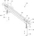
- FIG. 10is a view showing a tilt adjustment mechanism applied to an exercise device according to another embodiment.
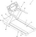
- FIG. 1is a perspective view showing a treadmill 1 according to an embodiment
- FIG. 2is a view for explaining the operation of the treadmill 1 according to the embodiment
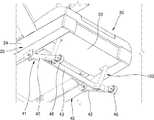
- 3is a partial perspective view of the treadmill 1 according to the embodiment viewed from a different angle
- FIG. 4is a view for explaining the operation of the tilt adjustment mechanism 40 of FIG. 3.
- the illustration of the holding part 50is omitted.
- the treadmill 1includes a track portion 10, a support mechanism 20 for supporting the track portion 10 so as to be rotatable, and a front side of the track portion 10. And a track driving unit 30 disposed on the track unit 10 to rotate and drive the track unit 10, and an inclination adjusting mechanism 40 configured to adjust the inclination of the track unit 10.
- the treadmill 1may further include a holding part 50.
- the holding unit 50includes a holding unit 51, a handle 52 attached to the other end of the holding unit 51, and a control panel 53 installed to allow a user to input an exercise program and view exercise information.
- the track portion 10may include a track belt 11 of an endless track type.
- the configuration of the track unit 10is not limited thereto, and may be variously modified.
- the track unit 10may include a plurality of slats arranged along the rotational direction instead of the track belt 11.
- the track driving unit 30includes a track driving motor 31 for rotatingly driving the track unit 10, a rotating belt 32 connected to the track driving motor 31, a track driving motor 31, and a rotating belt 32. ) Includes a front housing 33 configured so as not to be exposed to the outside. However, the track driving unit 30 may have an optional configuration, and the track driving unit 30 may be omitted in the manual treadmill 1 in which the track unit 10 is rotated by a user.
- the front housing 33may include a lower cover 34 and an upper cover 35 detachable from the lower cover 34.
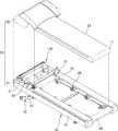
- the support mechanism 20is disposed between the drive roller 21 disposed in the front, the driven roller 22 disposed in the rear, and the drive roller 21 and the driven roller 22, and the inside of the track belt 11 It includes a deck 23 disposed on and a support frame 24 configured to support both sides of the deck 23.
- the drive roller 21may be connected to the track drive motor 31 by a rotating belt 32.
- dampers 25 and 26 for absorbing an impact applied to the deck 23may be disposed between the support frame 24 and the deck 23 between the support frame 24 and the deck 23.
- the dampers 25 and 26may include a damper 25 for absorbing a force applied vertically to the deck 23 and a damper 26 for absorbing a force applied horizontally to the deck 23.
- the tilt adjustment mechanism 40may be disposed under the front portion of the treadmill 1.
- the inclination adjustment mechanism 40includes an inclined support 41 connected to the support mechanism 20 so as to be rotatable, and a length adjustment module 100 connected to the inclined support 41 and adjustable in length. ).
- the inclined support part 41includes a pair of support members 42 and a connection member 43 that connects the pair of support members 42.
- Each of the pair of support members 42may have one end connected to the support frame 24 so as to be rotatable, and the other end may contact the floor F.
- a rotating member 46that rotates while contacting the floor F may be disposed.
- the length adjustment module 100may be partially exposed to the outside of the front housing 33 of the treadmill 1 and the other part may be disposed inside the front housing 33.
- the exposed part of the length adjustment module 100may be connected to the inclined support part 41 so as to be rotatable.
- the angle ⁇ 1 formed by the length adjustment module 100 and the inclined support part 41changes, and the angle formed by the inclined support part 41 and the support frame 24 ( ⁇ 2) is different.
- the angle ⁇ 2 of the inclined support part 41is changed, the angle ⁇ 3 of the support mechanism 20 with respect to the floor F and the angle ⁇ 3 of the track part 10 are changed.
- FIG. 5is a view showing a state in which the upper cover 35 is removed from the treadmill 1 according to the embodiment
- FIG. 6is a perspective view showing the length adjustment module 100 of FIG. 5 from a different angle.
- 7is a plan view of the length adjustment module 100 of FIG. 6
- FIG. 8is a perspective view of the length adjustment module 100 of FIG. 6 with the module box 150 omitted
- FIG. 9is a view of the length adjustment module of FIG. It is a cross-sectional view along AB.
- the length adjustment module 100includes one driving motor 110, first and second length adjustment members 120 and 130 whose length is adjusted by the driving motor 110, and It includes a connection belt 140 connecting the first and second length adjustment members 120 and 130.
- the first length adjustment member 120is disposed parallel to the second length adjustment member 130.
- the first length adjustment member 120 and the second length adjustment member 130are simultaneously adjusted in length.
- the first length adjustment member 120may be integrally formed with the driving motor 110.
- the first length adjustment member 120may be directly driven by the driving motor 110.
- the length L1 of the first length adjusting member 120 connected to the driving motor 110is adjusted.
- the driving force of the driving motor 110is transmitted to the second length adjustment member 130, in the process, the length of the second length adjustment member 130 (L2) is regulated.
- the inclination adjustment mechanism 40has a structure in which the inclination is adjusted as the length is adjusted by the two length adjustment members 120 and 130, it is possible to prevent the left and right shaking of the track unit 10. .
- the first length adjustment member 120includes a driving screw 121 that is rotationally driven by the driving motor 110 and a driving pulley that is disposed at an end of the driving screw 121 and is partially wound by a connection belt 140. 122) and a first moving part 123 formed on an inner circumferential surface of a driving female screw part 1231 that meshes with a thread of the driving screw 121.
- the driving screw 121is rotated by the driving motor 110, and the first moving part 123 is moved in the longitudinal direction by the rotation of the driving screw 121.
- the first moving part 123moves in a direction approaching the driving screw 121, and accordingly, the length of the first length adjusting member 120 (L1) becomes shorter.
- the driving screw 121rotates in a counterclockwise direction, the first moving part 123 moves in a direction away from the driving screw 121, and accordingly, the length of the first length adjusting member 120 (L1) becomes longer.
- the second length adjusting member 130is a driven screw 131 disposed in parallel with the driving screw 121 and a driven pulley disposed at the end of the driven screw 131 and partially wound by the connection belt 140 ( 132 and a driven female threaded portion 1331 meshing with the thread of the driven screw 131 includes a second moving portion 133 formed on an inner circumferential surface thereof.
- the driven pulley 132 connected by the connecting belt 140is rotated.
- the driven screw 131rotates by the rotation of the driven pulley 132, and accordingly, the second moving part 133 moves in the longitudinal direction.
- the second moving part 133moves in a direction approaching the driven screw 131, and accordingly, the length of the second length adjusting member 130 (L2) becomes shorter.
- the second moving part 133moves in a direction away from the driven screw 131, and accordingly, the length of the second length adjusting member 130 (L2) becomes longer.
- the connecting belt 140is configured to connect the driving pulley 122 and the driven pulley 132 and transmits a driving force from the driving pulley 122 to the driven pulley 132.
- connection belt 140In a configuration that connects the driving pulley 122 and the driven pulley 132, a plurality of connection gears may be considered instead of the connection belt 140.
- the plurality of connection gearsmay increase weight and cost as a result, and may generate noise that causes discomfort to the user.
- the connection belt 140compared to a plurality of connection gears, the connection belt 140 not only reduces weight and cost, but also minimizes noise.
- the connection belt 140includes a first curved section 1401 wound around the first length adjusting member 120 and a second curved section 1402 wound around the second length adjusting member 130, and the first curved section ( The first straight section 1403 connecting one end of 1401 and one end of the second curved section 1402, and the other end of the first curved section 1401 and the other end of the second straight section 1404 It connects and has a second straight section 1404 corresponding to the first straight section 1403.
- the first straight section 1403extends from the first curved section 1401
- the second curved section 1402extends from the first straight section 1403
- the second straight section 1404is a second curved section It extends from 1402, and the first curved section 1401 extends from the second straight section 1404.
- the length of the second straight section 1404 and the length of the first straight section 1403are the same, and the second straight section 1404 ) May be parallel to the first straight section 1403.
- the second straight section 1404corresponds to the first straight section 1403
- the second straight section 1404may not be parallel to the first straight section 1403.
- connection belt 140may include a material that is elastically deformed.
- the connecting belt 140may include rubber.
- the length adjustment module 100may further include a module box 150 in which the driving pulley 122, the driven pulley 132, and the connection belt 140 are accommodated.
- the module box 150may be disposed inside the track driving unit 30.
- the module box 150may be disposed in front of the track driving motor 31.
- the length adjustment module 100may further include a tension applying structure 151 that presses the second length adjustment member 130 away from the first length adjustment member 120.
- connection belt 140When the second length adjustment member 130 is pressed away from the first length adjustment member 120 by the tension applying structure 151, the connection belt 140 is elastically deformed, and in the process, the connection belt 140 May be in close contact with the first and second length adjustment members 120 and 130.
- the tension applying structure 151is installed in the module box 150 and is disposed in the pressing member 1511 for pressing the second length adjusting member 130, and is disposed in the module box 150 in the pressing direction of the pressing member 1511. It includes a plurality of elongated long holes 1512. A fixing member 135 for fixing the second length adjustment member 130 to the module box 150 is inserted into the plurality of elongated holes 1512.
- the fixing member 135is fixed to the plurality of long holes 1512 in a state where the second length adjusting member 130 is pressed away from the first length adjusting member 120 by the pressing member 1511. do. Accordingly, the connecting belt 140 wound around the driving pulley 122 and the driven pulley 132 is elastically pressed, and the connecting belt 140 is in close contact with the driving pulley 122 and the driven pulley 132.
- the first curved section 1401contacts the driving pulley 122, and the second curved section 1402 contacts the driven pulley 132.
- the lengths L31 and L32 of the first straight section 1403 and the second straight section 1404may be the same.
- the distance G between the first straight section 1403 and the second straight section 1404may correspond to the diameter of the driving pulley 122 or the diameter of the driven pulley 132.
- the width of the module box 150 ( W)can be designed small.
- the width W of the module box 150may be less than 120% of the diameter of the driving pulley 122.
- the width W of the module box 150may be 70 mm or less. In this case, the width W of the module box 150 is larger than the diameter of the driving pulley 122.
- support pillars 160 for rotatably supporting the module box 150are disposed on both sides of the module box 150.
- the rotation shaft 152 of the module box 150is rotatably supported on the support pillar 160.
- the module box 150may rotate around an imaginary line VL connecting the rotation axis A1 of the driving pulley 122 and the rotation axis A2 of the driven pulley 132.
- the radius of rotation of the module box 150is reduced. Accordingly, the height h1 of the support pillar 160 supporting the module box 150 may be lowered.
- the height h1 of the support pillar 160may be 12 cm or less.
- the height of the support pillar 160may be defined as the height h1 from the upper surface of the track belt 11.
- the height of the front housing 33may be designed to be low.
- the height of the upper cover 35can be designed to be low.
- the maximum height h2 of the track portion 10 of the front housing 33may be 15 cm or less.
- the driving motor 110adjusts the length L1 of the first length adjusting member 120, and the second length adjusting member 130 is connected to the first length adjusting member 120 through the connection belt 140. ) By acting to adjust the length (L2), it can be advantageous in various aspects.
- connection belt 140since the first length adjustment member 120 and the second length adjustment member 130 disposed spaced apart from each other are connected by the connection belt 140, the space occupied by the connection belt 140 can be reduced. . Accordingly, the turning radius of the module box 150 accommodating the connection belt 140 can be reduced, and the height of the track driving unit 30 can be lowered. This can obtain the effect of improving the design of the treadmill 1.
- the left and right weights of the treadmill 1can be designed in a balanced way.
- the track drive motor 31is heavier than the drive motor 110 of the tilt adjustment mechanism 40.
- the weight of the track drive motor 31may be 12 kg to 20 kg, while the weight of the drive motor 40 of the tilt adjustment mechanism 40 may be 2 kg to 5 kg.
- a relatively heavy track drive motor 31is relatively adjacent to the center between the drive pulley 122 and the driven pulley 132
- a relatively light driving motor 110may be disposed relatively far from the center between the driving pulley 122 and the driven pulley 132.
- the distance G1 from the center of the track driving motor 31 to the center between the driving pulley 122 and the driven pulley 132 along a direction perpendicular to the rotation direction of the track belt 11is 130 mm It may be ⁇ 200 mm, and the distance (G2) from the center of the drive motor 110 to the center between the drive pulley 122 and the driven pulley 132 along a direction perpendicular to the rotation direction of the track belt 11 It may be 270 mm to 320 mm.
- the center between the driving pulley 122 and the driven pulley 132may coincide with the center of the front housing 33.
- the tilt adjustment mechanism 40is used for the treadmill 1 .
- the tilt adjustment mechanism 40 according to the embodimentis not limited thereto, and may be variously applied as long as it is a device requiring tilt adjustment.
- the exercise device 2is a view showing a tilt adjustment mechanism (40a) applied to the exercise device (2) according to another embodiment.
- the exercise device 2according to the embodiment includes a track portion 10, a support mechanism 20 for supporting the track portion 10 so as to be rotatable, and rotationally driving the track portion 10
- a track drive unit 30 and an inclination adjustment mechanism 40a for adjusting the inclination of the track unit 10are included.
- the support mechanism 20is supported so as to be rotatable with respect to the base portion 180.
- the tilt adjustment mechanism 40amay be disposed under the track portion 10.
- the tilt adjustment mechanism 40aincludes one driving motor 110, first and second length adjustment members 120 and 130 whose length is adjusted by the driving motor 110, and first and second length adjustment members. It includes a connecting belt 140 (see Fig. 7) connecting the (120, 130).
- One end of the first and second length adjustment members 120 and 130is rotatably connected to the connection portion 27 of the support mechanism 20.
- a driving pulley 122see FIG. 7
- a driven pulley 132see FIG. 7
- a connection belt 140 connecting themmay be accommodated inside the module box 150.
- the module box 150may be rotatably supported on the support pillar 160 of the base unit 180.
- the length adjustment module 100 including a pair of length adjustment members 120 and 130has been described based on an example in which the tilt adjustment mechanism 40 is applied.
- the application of the length adjustment module 100is not limited to the tilt adjustment mechanism 40, and can be applied to various devices, of course.
Landscapes
- Health & Medical Sciences (AREA)
- General Health & Medical Sciences (AREA)
- Physical Education & Sports Medicine (AREA)
- Cardiology (AREA)
- Vascular Medicine (AREA)
- Life Sciences & Earth Sciences (AREA)
- Biophysics (AREA)
- Orthopedic Medicine & Surgery (AREA)
- Rehabilitation Tools (AREA)
Abstract
Description
Translated fromKorean본 발명은 길이조절 모듈, 경사 조절 기구 및 이를 포함하는 트레드밀에 관한 것이다.The present invention relates to a length adjustment module, an inclination adjustment mechanism, and a treadmill including the same.
트레드밀은 무한 궤도로 회전하는 벨트를 이용하여 좁은 공간에서 걷거나 뛰는 운동 효과를 가져올 수 있는 운동 기구로서, 러닝머신으로 불려진다. 트레드밀은, 날씨에 관계 없이, 적당한 온도의 실내에서 걷기 또는 러닝(running) 운동을 할 수 있으므로 나날이 그 수요가 급증하고 있다.A treadmill is an exercise device that can bring about the effect of walking or running in a narrow space by using a belt rotating in an endless track, and is called a treadmill. The demand for treadmills is increasing day by day, since it is possible to perform walking or running exercise indoors at an appropriate temperature regardless of the weather.
이러한 트레드밀은 운동 효과를 극대화하거나 다양한 운동 환경을 제공하기 위하여, 트랙부의 경사도를 조절할 수 있는 경사 조절 기구를 더 포함할 수 있다.Such a treadmill may further include a tilt adjustment mechanism capable of adjusting the inclination of the track portion in order to maximize an exercise effect or provide a variety of exercise environments.
다만, 이러한 경사 조절 기구는 1개의 길이 조절부재에 의해 경사도를 조절하는 싱글(single) 타입과, 2개의 길이 조절부재에 의해 경사도를 조절하는 듀얼(dual) 타입으로 분류될 수 있다.However, such a tilt adjustment mechanism may be classified into a single type for adjusting the inclination by one length adjusting member and a dual type for adjusting the inclination by two length adjusting members.
싱글 타입의 경사 조절 기구는, 그 구조가 단순하다는 장점이 있으나, 트랙부의 안정성이 떨어진다는 단점이 있다.The single-type inclination adjustment mechanism has the advantage that its structure is simple, but has a disadvantage in that the stability of the track portion is poor.
반면, 듀얼 타입의 경사 조절 기구는, 싱글 타입의 경사 조절 기구에 비해 트랙부의 안정성이 있으나, 2개의 길이 조절부재를 동시에 작동하기 위한 구조가 복잡하고 그 크기가 커진다는 단점이 있다.On the other hand, the dual-type inclination adjustment mechanism has the stability of the track portion compared to the single-type inclination adjustment mechanism, but has a disadvantage in that the structure for simultaneously operating two length adjustment members is complicated and the size thereof is increased.
본 발명은, 트랙부의 안정성을 확보하면서도 그 구조가 단순하고 크기 증가를 최소화할 수 있는 길이조절 모듈, 경사 조절 기구 및 이를 포함하는 트레드밀을 제공한다.The present invention provides a length adjustment module, an inclination adjustment mechanism, and a treadmill including the same, which have a simple structure and minimize an increase in size while securing the stability of the track portion.
본 발명의 일 측면에 따른 트레드밀은,A treadmill according to an aspect of the present invention,
트랙부와, 상기 트랙부를 회전 가능하도록 지지하는 지지 기구와, 상기 트랙부의 경사를 조절하도록 구성된 경사 조절 기구를 포함하는 트레드밀로서,A treadmill comprising a track portion, a support mechanism for rotatably supporting the track portion, and an inclination adjustment mechanism configured to adjust the inclination of the track portion,
상기 경사 조절 기구는 길이가 조절되는 길이조절 모듈을 포함하며, 길이가 조절됨에 따라 바닥에 대한 트랙부의 경사 각도가 달라지도록 구성되며,The inclination adjustment mechanism includes a length adjustment module in which the length is adjusted, and as the length is adjusted, the inclination angle of the track portion with respect to the floor is changed,
상기 길이조절 모듈은,The length adjustment module,
구동 모터;Drive motor;
상기 구동 모터의 구동력에 의해 길이가 조절되는 제1 길이 조절부재;A first length adjusting member whose length is adjusted by a driving force of the driving motor;
일부가 상기 제1 길이 조절부재에 감겨진 연결 벨트; 및A connection belt partially wound around the first length adjustment member; And
상기 제1 길이 조절부재와 평행하게 배치되며, 상기 연결 벨트에 의해 상기 제1 길이 조절부재에 연결되며, 상기 제1 길이 조절부재 및 상기 연결벨트를 통해 상기 구동 모터의 구동력을 전달받아 길이가 조절되는 제2 길이 조절부재;를 포함하며,Arranged in parallel with the first length adjusting member, connected to the first length adjusting member by the connection belt, the length is adjusted by receiving the driving force of the driving motor through the first length adjusting member and the connection belt Includes; a second length adjustment member that is,
상기 연결 벨트는,The connecting belt,
상기 제1 길이 조절부재에 감겨진 제1 곡선 구간과, 상기 제2 길이 조절부재에 감겨진 제2 곡선 구간과, 상기 제1 곡선 구간의 일 단부와 상기 제2 곡선 구간의 일 단부를 연결하는 제1 직선 구간과, 상기 제1 곡선 구간의 타 단부와 상기 제2 곡선 구간의 타 단부를 연결하며 상기 제1 직선 구간에 대응하는 제2 직선 구간을 가질 수 있다.Connecting a first curved section wound around the first length adjusting member, a second curved section wound around the second length adjusting member, and one end of the first curved section and one end of the second curved section The first straight section may connect the other end of the first curved section to the other end of the second curved section and have a second straight section corresponding to the first straight section.
일 실시예에 있어서, 상기 제1 길이 조절부재는, 상기 구동 모터에 의해 회전 구동되는 구동 스크류와, 상기 구동 스크류의 단부에 배치되며 상기 연결 벨트에 의해 일부가 감겨진 구동 풀리와, 상기 구동 스크류의 나사산과 맞물리는 구동 암나사부가 내주면에 형성되며 길이 방향으로 이동하는 제1 이동부를 포함하며, 상기 제2 길이 조절부재는, 상기 구동 스크류와 평행하게 배치된 종동 스크류와, 상기 종동 스크류의 단부에 배치되며 상기 연결 벨트에 의해 일부가 감겨진 종동 풀리와, 상기 종동 스크류의 나사산과 맞물리는 종동 암나사부가 내주면에 형성되며 길이 방향으로 이동하는 제2 이동부를 포함할 수 있다.In an embodiment, the first length adjusting member includes a driving screw that is rotationally driven by the driving motor, a driving pulley disposed at an end of the driving screw and partially wound by the connection belt, and the driving screw. A driving female screw portion engaged with the screw thread of is formed on an inner circumferential surface and includes a first moving portion that moves in a longitudinal direction, and the second length adjusting member includes a driven screw disposed parallel to the driving screw, and an end portion of the driven screw The driven pulley is disposed and partially wound by the connection belt, and a driven female threaded portion engaged with the thread of the driven screw is formed on the inner circumferential surface and may include a second moving portion that moves in the longitudinal direction.
일 실시예에 있어서, 상기 연결 벨트의 제1 직선 구간과 상기 제2 직선 구간 사이의 거리는, 상기 구동 풀리의 직경 또는 상기 종동 풀리의 직경에 대응할 수 있다.In one embodiment, a distance between the first straight section and the second straight section of the connection belt may correspond to a diameter of the driving pulley or a diameter of the driven pulley.
일 실시예에 있어서, 상기 구동 풀리, 상기 종동 풀리 및 연결 벨트가 수납되는 모듈 박스를 더 포함할 수 있다.In one embodiment, a module box in which the driving pulley, the driven pulley, and the connection belt are accommodated may be further included.
일 실시예에 있어서, 상기 모듈 박스의 폭은 상기 구동 풀리의 직경보다 크며, 상기 구동 풀리의 직경의 120%보다 작을 수 있다.In one embodiment, a width of the module box may be greater than a diameter of the driving pulley and less than 120% of a diameter of the driving pulley.
일 실시예에 있어서, 상기 모듈 박스가 상기 구동 풀리의 회전축과 상기 종동 풀리의 회전축을 연결하는 가상선을 중심으로 회동 가능하도록, 상기 모듈 박스를 지지하는 지지 기둥을 더 포함할 수 있다.In one embodiment, the module box may further include a support pillar for supporting the module box so that the module box can be rotated about a virtual line connecting the rotation axis of the driving pulley and the rotation axis of the driven pulley.
일 실시예에 있어서, 상기 지지 기둥의 높이는 12 cm 이하일 수 있다.In one embodiment, the height of the support pillar may be 12 cm or less.
일 실시예에 있어서, 상기 트랙부의 전방에 배치되며, 상기 트랙부를 회전 구동시키는 트랙 구동부를 더 포함하며, 상기 트랙 구동부는, 전방 하우징과, 상기 전방 하우징의 내부에 수납되며 상기 트랙부를 회전 구동시키기 위한 트랙 구동모터를 포함할 수 있다.In one embodiment, further comprising a track driving unit disposed in front of the track unit to rotate the track unit, the track driving unit is accommodated in the front housing and the front housing to rotate the track unit It may include a track drive motor for.
일 실시예에 있어서, 상기 지지 기둥은 상기 전방 하우징의 내부에 배치되며, 상기 전방 하우징의 트랙부에 대한 최대 높이는 15 cm 이하일 수 있다.In one embodiment, the support pillar is disposed inside the front housing, and a maximum height of the front housing with respect to the track portion may be 15 cm or less.
일 실시예에 있어서, 상기 트랙 구동모터는 상기 구동 모터보다 무거우며, 상기 트랙 구동모터가 상기 구동 모터에 비해 상기 전방 하우징의 중심에 인접하도록 배치될 수 있다.In one embodiment, the track driving motor is heavier than the driving motor, and the track driving motor may be disposed closer to the center of the front housing than the driving motor.
일 실시예에 있어서, 상기 제2 길이 조절부재를 상기 제1 길이 조절부재로부터 멀어지도록 가압하는 장력 인가 구조를 더 포함할 수 있다.In one embodiment, a tension applying structure for pressing the second length adjusting member away from the first length adjusting member may be further included.
본 발명의 다른 측면에 따르면, 트랙부의 경사를 조절하도록 길이가 조절되는 길이조절 모듈을 포함하는 경사 조절 기구로서,According to another aspect of the present invention, as a slope adjustment mechanism comprising a length adjustment module, the length is adjusted to adjust the slope of the track portion,
상기 길이조절 모듈은,The length adjustment module,
구동 모터;Drive motor;
상기 구동 모터의 구동력에 의해 길이가 조절되는 제1 길이 조절부재;A first length adjusting member whose length is adjusted by a driving force of the driving motor;
일부가 상기 제1 길이 조절부재에 감겨진 연결 벨트;A connection belt partially wound around the first length adjustment member;
상기 제1 길이 조절부재와 평행하게 배치되며, 상기 연결 벨트에 의해 상기 제1 길이 조절부재에 연결되며, 상기 제1 길이 조절부재 및 상기 연결벨트를 통해 상기 구동 모터의 구동력을 전달받아 길이가 조절되는 제2 길이 조절부재;를 포함하며,Arranged in parallel with the first length adjusting member, connected to the first length adjusting member by the connection belt, the length is adjusted by receiving the driving force of the driving motor through the first length adjusting member and the connection belt Includes; a second length adjustment member that is,
상기 연결 벨트는,The connecting belt,
상기 제1 길이 조절부재에 감겨진 제1 곡선 구간과,A first curved section wound around the first length adjusting member,
상기 제2 길이 조절부재에 감겨진 제2 곡선 구간과,A second curved section wound around the second length adjusting member,
상기 제1 곡선 구간의 일 단부와 상기 제2 곡선 구간의 일 단부를 연결하는 제1 직선 구간과,A first straight section connecting one end of the first curved section and one end of the second curved section,
상기 제1 곡선 구간의 타 단부와 상기 제2 곡선 구간의 타 단부를 연결하며, 상기 제1 직선 구간에 대응하는 제2 직선 구간을 가질 수 있다.The other end of the first curved section and the other end of the second curved section may be connected, and a second straight section corresponding to the first straight section may be provided.
본 발명의 또 다른 측면에 따르면, 길이가 조절되는 길이조절 모듈로서,According to another aspect of the present invention, as a length adjustment module in which the length is adjusted,
구동 모터;Drive motor;
상기 구동 모터의 구동력에 의해 길이가 조절되는 제1 길이 조절부재;A first length adjusting member whose length is adjusted by a driving force of the driving motor;
일부가 상기 제1 길이 조절부재에 감겨진 연결 벨트;A connection belt partially wound around the first length adjustment member;
상기 제1 길이 조절부재와 평행하게 배치되며, 상기 연결 벨트에 의해 상기 제1 길이 조절부재에 연결되며, 상기 제1 길이 조절부재 및 상기 연결벨트를 통해 상기 구동 모터의 구동력을 전달받아 길이가 조절되는 제2 길이 조절부재;를 포함하며,Arranged in parallel with the first length adjusting member, connected to the first length adjusting member by the connection belt, the length is adjusted by receiving the driving force of the driving motor through the first length adjusting member and the connection belt Includes; a second length adjustment member that is,
상기 연결 벨트는,The connecting belt,
상기 제1 길이 조절부재에 감겨진 제1 곡선 구간과,A first curved section wound around the first length adjusting member,
상기 제2 길이 조절부재에 감겨진 제2 곡선 구간과,A second curved section wound around the second length adjusting member,
상기 제1 곡선 구간의 일 단부와 상기 제2 곡선 구간의 일 단부를 연결하는 제1 직선 구간과,A first straight section connecting one end of the first curved section and one end of the second curved section,
상기 제1 곡선 구간의 타 단부와 상기 제2 곡선 구간의 타 단부를 연결하며, 상기 제1 직선 구간에 대응하는 제2 직선 구간을 가질 수 있다.The other end of the first curved section and the other end of the second curved section may be connected, and a second straight section corresponding to the first straight section may be provided.
전술한 것 외의 다른 측면, 특징, 이점이 이하의 도면, 특허청구범위 및 발명의 상세한 설명으로부터 명확해질 것이다.Other aspects, features, and advantages other than those described above will become apparent from the following drawings, claims, and detailed description of the invention.
이러한 일반적이고 구체적인 측면이 시스템, 방법, 컴퓨터 프로그램, 또는 어떠한 시스템, 방법, 컴퓨터 프로그램의 조합을 사용하여 실시될 수 있다.These general and specific aspects can be implemented using a system, method, computer program, or any combination of systems, methods, and computer programs.
본 발명의 실시예의 길이조절 모듈, 경사 조절 기구 및 이를 포함하는 트레드밀에 따르면, 그 구조가 단순하고 크기 증가를 최소화면서도 트랙부의 안정성을 향상시킬 수 있다.According to the length adjustment module, the inclination adjustment mechanism, and the treadmill including the same according to an embodiment of the present invention, the structure thereof is simple and the size increase is minimized, while the stability of the track portion can be improved.
도 1은 실시예에 따른 트레드밀을 나타낸 사시도이며,1 is a perspective view showing a treadmill according to an embodiment,
도 2는 실시예에 따른 트레드밀의 작동을 설명하기 위한 도면이다.2 is a view for explaining the operation of the treadmill according to the embodiment.
도 3은 실시예에 따른 트레드밀을 다른 각도에서 바라본 부분 사시도이며,3 is a partial perspective view of the treadmill according to the embodiment viewed from a different angle,
도 4는 도 3의 경사 조절 기구의 작동을 설명하기 위한 도면이다.4 is a view for explaining the operation of the tilt adjustment mechanism of FIG. 3.
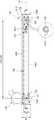
도 5는 실시예에 따른 트레드밀에서 상부 커버를 제거한 상태를 나타낸 도면이며,5 is a view showing a state in which the upper cover is removed from the treadmill according to the embodiment,
도 6은 도 5의 길이조절 모듈을 다른 각도에서 나타낸 사시도이다.6 is a perspective view showing the length adjustment module of FIG. 5 from a different angle.
도 7은 도 6의 길이조절 모듈의 평면도이며,Figure 7 is a plan view of the length adjustment module of Figure 6,
도 8은 도 6의 길이조절 모듈에서 모듈 박스를 생략한 사시도이며,Figure 8 is a perspective view of the module box omitted from the length adjustment module of Figure 6,
도 9는 도 8의 길이조절 모듈의 AB에 따른 단면도이다.9 is a cross-sectional view of the length adjustment module of FIG. 8 taken along AB.
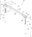
도 10은 다른 실시예에 따른 운동 기구에 적용된 경사 조절 기구를 나타낸 도면이다.10 is a view showing a tilt adjustment mechanism applied to an exercise device according to another embodiment.
이하, 첨부된 도면을 참조하여 본 발명의 실시예를 상세히 설명한다. 도면에서 동일한 참조부호는 동일한 구성요소를 지칭하며, 각 구성요소의 크기나 두께는 설명의 명료성을 위하여 과장되어 있을 수 있다.Hereinafter, exemplary embodiments of the present invention will be described in detail with reference to the accompanying drawings. In the drawings, the same reference numerals refer to the same components, and the size or thickness of each component may be exaggerated for clarity of description.
도 1은 실시예에 따른 트레드밀(1)을 나타낸 사시도이며, 도 2는 실시예에 따른 트레드밀(1)의 작동을 설명하기 위한 도면이다. 도 3은 실시예에 따른 트레드밀(1)을 다른 각도에서 바라본 부분 사시도이며, 도 4는 도 3의 경사 조절 기구(40)의 작동을 설명하기 위한 도면이다. 도 2에서는, 설명의 편의를 위하여, 지주부(50)에 대한 도시를 생략하였다.1 is a perspective view showing a
도 1 및 도 2를 참조하면, 실시예에 따른 트레드밀(1)은 트랙부(10), 이러한 트랙부(10)를 회전 가능하도록 지지하는 지지 기구(20)와, 트랙부(10)의 전방에 배치되며 트랙부(10)를 회전 구동시키는 트랙 구동부(30)와, 트랙부(10)의 경사를 조절하도록 구성된 경사 조절 기구(40)를 포함한다.1 and 2, the
트레드밀(1)은 지주부(50)를 더 포함할 수 있다. 지주부(50)는 지주(51)와, 지주(51)의 타단에 부착된 손잡이(52)와, 사용자가 운동 프로그램을 입력하고 운동 정보를 볼 수 있도록 설치된 제어판(53)을 포함한다.The
트랙부(10)는 무한 궤도 타입의 트랙 벨트(11)를 포함할 수 있다. 다만, 트랙부(10)의 구성은 이에 한정되지 아니하며, 다양하게 변형될 수 있다. 예를 들어, 도면상 도시되지 않았지만, 트랙부(10)는 트랙 벨트(11) 대신에 회전 방향을 따라 배열된 복수의 슬래트를 포함할 수 있다.The
트랙 구동부(30)는 트랙부(10)를 회전 구동시키기 위한 트랙 구동모터(31)와, 트랙 구동모터(31)에 연결된 회전 벨트(32)와, 트랙 구동모터(31)와 회전 벨트(32)가 외부로 노출되지 않도록 구성된 전방 하우징(33)을 포함한다. 다만, 트랙 구동부(30)는 선택적인 구성일 수 있으며, 사용자에 의해 트랙부(10)가 회전하는 수동 트레드밀(1)에서는 트랙 구동부(30)가 생략될 수 있다.The
전방 하우징(33)은 하부 커버(34)와, 이러한 하부 커버(34)로부터 분리 가능한 상부 커버(35)를 포함할 수 있다.The
지지 기구(20)는, 전방에 배치된 구동 롤러(21), 후방에 배치된 종동 롤러(22)와, 구동 롤러(21)와 종동 롤러(22) 사이에 배치되며 트랙 벨트(11)의 내부에 배치된 데크(23)와, 데크(23)의 양 측부를 지지하도록 구성된 지지 프레임(24)을 포함한다. 구동 롤러(21)는 회전 벨트(32)에 의해 트랙 구동모터(31)에 연결될 수 있다.The
지지 프레임(24)과 데크(23) 사이에는, 데크(23)에 가해진 충격을 흡수하기 위한 댐퍼(25, 26)가 배치될 수 있다. 댐퍼(25, 26)는 데크(23)에 수직으로 가해진 힘을 흡수하기 위한 댐퍼(25)와 데크(23)에 수평으로 가해진 힘을 흡수하기 위한 댐퍼(26)를 포함할 수 있다.Between the
경사 조절 기구(40)는 트레드밀(1)의 전방 부분의 아래에 배치될 수 있다.The
도 3 및 도 4를 참조하면, 경사 조절 기구(40)는 지지 기구(20)에 회동 가능하도록 연결된 경사 지지부(41)와, 경사 지지부(41)에 연결되며 길이가 조절되는 길이조절 모듈(100)을 포함한다.3 and 4, the
경사 지지부(41)는 한 쌍의 지지 부재(42)와, 한 쌍의 지지 부재(42)를 연결하는 연결 부재(43)를 포함한다. 한 쌍의 지지 부재(42) 각각은, 일 단부가 지지 프레임(24)에 회동 가능하도록 연결되며, 타 단부가 바닥(F)에 접촉될 수 있다. 지지 부재(42)의 타 단부에는 바닥(F)과 접촉하며 회전하는 회전 부재(46)가 배치될 수 있다.The
길이조절 모듈(100)은, 일부가 트레드밀(1)의 전방 하우징(33)의 외부로 노출되며, 다른 일부가 전방 하우징(33)의 내부에 배치될 수 있다. 길이조절 모듈(100)의 노출된 일부는, 경사 지지부(41)에 회동 가능하도록 연결될 수 있다.The
길이조절 모듈(100)의 길이가 조절됨에 따라, 길이조절 모듈(100)과 경사 지지부(41)가 이루는 각도(θ1)가 달라지며, 경사 지지부(41)와 지지 프레임(24)이 이루는 각도(θ2)가 달라진다. 경사 지지부(41)의 각도(θ2)가 달라짐에 따라, 바닥(F)에 대한 지지 기구(20)의 각도 및 트랙부(10)의 각도(θ3)가 달라진다.As the length of the
도 5는 실시예에 따른 트레드밀(1)에서 상부 커버(35)를 제거한 상태를 나타낸 도면이며, 도 6은 도 5의 길이조절 모듈(100)을 다른 각도에서 나타낸 사시도이다. 도 7은 도 6의 길이조절 모듈(100)의 평면도이며, 도 8은 도 6의 길이조절 모듈(100)에서 모듈 박스(150)를 생략한 사시도이며, 도 9는 도 8의 길이조절 모듈의 AB에 따른 단면도이다.5 is a view showing a state in which the
도 5 내지 도 9를 참조하면, 길이조절 모듈(100)은 하나의 구동 모터(110)와, 구동 모터(110)에 의해 길이가 조절되는 제1, 제2 길이 조절부재(120, 130)와, 제1, 제2 길이 조절부재(120, 130)를 연결하는 연결 벨트(140)를 포함한다.5 to 9, the
제1 길이 조절부재(120)는 제2 길이 조절부재(130)와 평행하게 배치된다. 제1 길이 조절부재(120)와 제2 길이 조절부재(130)는 동시에 길이가 조절된다.The first
제1 길이 조절부재(120)는 구동 모터(110)와 일체로 형성될 수 있다. 제1 길이 조절부재(120)는 구동 모터(110)에 의해 직접 구동될 수 있다.The first
구동 모터(110)가 구동됨에 따라, 구동 모터(110)에 연결된 제1 길이 조절부재(120)의 길이(L1)가 조절된다. 제1 길이 조절부재(120) 및 연결 벨트(140)를 통해, 구동 모터(110)의 구동력은 제2 길이 조절부재(130)로 전달되며, 그 과정에서 제2 길이 조절부재(130)의 길이(L2)가 조절된다.As the driving
이와 같이, 경사 조절 기구(40)는 2개의 길이 조절부재(120, 130)에 의해 길이가 조절됨에 따라 경사가 조절되는 구조를 가지기 때문에, 트랙부(10)의 좌우 흔들림을 방지할 수 있다..As described above, since the
제1 길이 조절부재(120)는 구동 모터(110)에 의해 회전 구동되는 구동 스크류(121)와, 구동 스크류(121)의 단부에 배치되며 연결 벨트(140)에 의해 일부가 감겨진 구동 풀리(122)와, 구동 스크류(121)의 나사산과 맞물리는 구동 암나사부(1231)가 내주면에 형성된 제1 이동부(123)를 포함한다.The first
구동 모터(110)에 의해 구동 스크류(121)가 회전되며, 구동 스크류(121)의 회전에 의해 제1 이동부(123)가 길이 방향으로 이동하게 된다. 예를 들어, 구동 스크류(121)가 시계 방향으로 회전함에 따라, 제1 이동부(123)가 구동 스크류(121)에 접근하는 방향으로 이동하며, 그에 따라 제1 길이 조절부재(120)의 길이(L1)가 짧아진다. 예를 들어, 구동 스크류(121)가 반시계 방향으로 회전함에 따라, 제1 이동부(123)가 구동 스크류(121)에 멀어지는 방향으로 이동하며, 그에 따라 제1 길이 조절부재(120)의 길이(L1)가 길어진다.The driving
제2 길이 조절부재(130)는 구동 스크류(121)와 평행하게 배치된 종동 스크류(131)와, 종동 스크류(131)의 단부에 배치되며 연결 벨트(140)에 의해 일부가 감겨진 종동 풀리(132)와, 종동 스크류(131)의 나사산과 맞물리는 종동 암나사부(1331)가 내주면에 형성된 제2 이동부(133)를 포함한다.The second
구동 풀리(122)가 회전됨에 따라, 연결 벨트(140)에 의해 연결된 종동 풀리(132)가 회전된다. 종동 풀리(132)의 회전에 의해 종동 스크류(131)가 회전하며, 그에 따라 제2 이동부(133)가 길이 방향으로 이동하게 된다. 예를 들어, 종동 스크류(131)가 시계 방향으로 회전함에 따라, 제2 이동부(133)가 종동 스크류(131)에 접근하는 방향으로 이동하며, 그에 따라 제2 길이 조절부재(130)의 길이(L2)가 짧아진다. 예를 들어, 종동 스크류(131)가 반시계 방향으로 회전함에 따라, 제2 이동부(133)가 종동 스크류(131)에 멀어지는 방향으로 이동하며, 그에 따라 제2 길이 조절부재(130)의 길이(L2)가 길어진다.As the driving
연결 벨트(140)는 구동 풀리(122)와 종동 풀리(132)를 연결하는 구성으로, 구동 풀리(122)로부터 종동 풀리(132)로 구동력을 전달한다.The connecting
구동 풀리(122)와 종동 풀리(132)를 연결하는 구성으로, 연결 벨트(140) 대신에 복수의 연결 기어를 고려해볼 수 있다. 그러나, 복수의 연결 기어는 그로 인해 무게 및 비용이 증가할 뿐만 아니라, 사용자에게 불편감을 주는 소음이 발생시킬 수 있다. 그에 반해, 연결 벨트(140)는 복수의 연결 기어에 비해, 무게 및 비용이 감소할 뿐만 아니라, 소음을 최소화할 수 있다.In a configuration that connects the driving
연결 벨트(140)는 제1 길이 조절부재(120)에 감겨진 제1 곡선 구간(1401)과 제2 길이 조절부재(130)에 감겨진 제2 곡선 구간(1402)과, 제1 곡선 구간(1401)의 일 단부와 제2 곡선 구간(1402)의 일 단부를 연결하는 제1 직선 구간(1403)과, 제1 곡선 구간(1401)의 타 단부와 제2 직선 구간(1404)의 타 단부를 연결하며 제1 직선 구간(1403)에 대응하는 제2 직선 구간(1404)을 가진다.The
제1 직선 구간(1403)은 제1 곡선 구간(1401)으로부터 연장되며, 제2 곡선 구간(1402)은 제1 직선 구간(1403)으로부터 연장되며, 제2 직선 구간(1404)은 제2 곡선 구간(1402)으로부터 연장되며, 제1 곡선 구간(1401)은 제2 직선 구간(1404)으로부터 연장된다.The first
제2 직선 구간(1404)이 제1 직선 구간(1403)에 대응하는 예로서, 제2 직선 구간(1404)의 길이와 제1 직선 구간(1403)의 길이가 동일하며, 제2 직선 구간(1404)이 제1 직선 구간(1403)과 평행할 수 있다.As an example in which the second
도시하지 않았으나, 제2 직선 구간(1404)이 제1 직선 구간(1403)에 대응하는 예로서, 구동 풀리(122)와 종동 풀리(132)의 직경이 다를 경우, 제2 직선 구간(1404)의 길이와 제1 직선 구간(1403)의 길이가 동일하며, 제2 직선 구간(1404)은 제1 직선 구간(1403)과 평행하지 않을 수 있다.Although not shown, as an example in which the second
연결 벨트(140)는 탄성적으로 변형되는 재질을 포함할 수 있다. 예를 들어, 연결 벨트(140)는 고무를 포함할 수 있다.The
길이조절 모듈(100)은 구동 풀리(122), 종동 풀리(132) 및 연결 벨트(140)가 수납되는 모듈 박스(150)를 더 포함할 수 있다. 모듈 박스(150)는 트랙 구동부(30)의 내부에 배치될 수 있다. 모듈 박스(150)는 트랙 구동모터(31)의 전방에 배치될 수 있다.The
길이조절 모듈(100)은 제2 길이 조절부재(130)를 제1 길이 조절부재(120)로부터 멀어지도록 가압하는 장력 인가 구조물(151)을 더 포함할 수 있다.The
장력 인가 구조물(151)에 의해 제2 길이 조절부재(130)가 제1 길이 조절부재(120)로부터 멀어지도록 가압될 경우, 연결 벨트(140)는 탄성 변형되며, 그 과정에서 연결 벨트(140)는 제1, 제2 길이 조절부재(120, 130)에 밀착될 수 있다.When the second
장력 인가 구조물(151)은 모듈 박스(150)에 설치되며 제2 길이 조절부재(130)를 가압하는 가압 부재(1511)와, 모듈 박스(150)에 배치되며 가압 부재(1511)의 가압 방향으로 연장된 복수의 장공(1512)을 포함한다. 상기 복수의 장공(1512)에는 제2 길이 조절부재(130)를 모듈 박스(150)에 고정하기 위한 고정 부재(135)가 삽입된다.The
조립 과정에서, 가압 부재(1511)에 의해 제2 길이 조절부재(130)를 제1 길이 조절부재(120)로부터 멀어지도록 가압한 상태에서, 복수의 장공(1512)에 고정 부재(135)를 고정한다. 그에 따라, 구동 풀리(122) 및 종동 풀리(132)에 감겨진 연결 벨트(140)가 탄성 가압되며, 연결 벨트(140)는 구동 풀리(122)와 종동 풀리(132)에 밀착된다. 제1 곡선 구간(1401)은 구동 풀리(122)에 접촉하며, 제2 곡선 구간(1402)은 종동 풀리(132)에 접촉한다.In the assembling process, the fixing
제1 직선 구간(1403)과 제2 직선 구간(1404)의 길이(L31, L32)는 서로 동일할 수 있다. 제1 직선 구간(1403)과 제2 직선 구간(1404) 사이의 거리(G)는 구동 풀리(122)의 직경 또는 종동 풀리(132)의 직경에 대응할 수 있다.The lengths L31 and L32 of the first
제1 직선 구간(1403)과 제2 직선 구간(1404) 사이의 거리(G)가 구동 풀리(122) 또는 종동 풀리(132)의 직경에 대응하도록 작아짐에 따라, 모듈 박스(150)의 폭(W)을 작게 설계할 수 있다.As the distance G between the first
예를 들어, 모듈 박스(150)의 폭(W)은 구동 풀리(122)의 직경의 120% 보다 작을 수 있다. 예를 들어, 모듈 박스(150)의 폭(W)은 70 mm 이하일 수 있다. 이 때, 모듈 박스(150)의 폭(W)은 구동 풀리(122)의 직경보다 크다.For example, the width W of the
모듈 박스(150)의 양 측부에는, 모듈 박스(150)를 회동 가능하게 지지하는 지지 기둥(160)이 배치된다. 모듈 박스(150)의 회동축(152)이 지지 기둥(160)에 회동 가능하게 지지된다.On both sides of the
모듈 박스(150)는 구동 풀리(122)의 회전축(A1)과 종동 풀리(132)의 회전축(A2)을 연결하는 가상선(VL)을 중심으로 회동할 수 있다.The
모듈 박스(150)의 크기를 작게 함으로써, 모듈 박스(150)의 회전 반경이 작아지게 된다. 그에 따라, 모듈 박스(150)를 지지하는 지지 기둥(160)의 높이(h1)를 낮게 할 수 있다. 예를 들어, 지지 기둥(160)의 높이(h1)가 12 cm 이하일 수 있다. 여기서, 지지 기둥(160)의 높이는 트랙 벨트(11)의 상부면으로부터의 높이(h1)로 정의될 수 있다.By reducing the size of the
지지 기둥(160)의 높이(h1)가 낮아짐에 따라, 전방 하우징(33)의 높이를 낮게 설계할 수 있다. 상부 커버(35)의 높이를 낮게 설계할 수 있다. 예를 들어, 전방 하우징(33)의 트랙부(10)의 대한 최대 높이(h2)는 15 cm 이하일 수 있다.As the height h1 of the
상기와 같이, 구동 모터(110)가 제1 길이 조절부재(120)의 길이(L1)를 조절하고, 연결 벨트(140)를 통해 제2 길이 조절부재(130)가 제1 길이 조절부재(120)에 종동하여 길이(L2)가 조절되도록 작동함으로써, 다양한 측면에서 유리할 수 있다.As described above, the driving
먼저, 상술한 것처럼, 서로 이격 배치된 제1 길이 조절부재(120)와 제2 길이 조절부재(130)가 연결 벨트(140)에 의해 연결되므로, 연결 벨트(140)가 차지하는 공간을 줄일 수 있다. 그에 따라, 이러한 연결 벨트(140)를 수납한 모듈 박스(150)의 회전 반경을 줄일 수 있으며, 트랙 구동부(30)의 높이를 낮출 수 있게 된다. 이는, 트레드밀(1)의 디자인을 개선하는 효과를 얻을 수 있다.First, as described above, since the first
다음으로, 트레드밀(1)의 좌우 무게를 균형감 있게 설계할 수 있다. 일반적으로 트랙 구동모터(31)는 경사 조절 기구(40)의 구동 모터(110)보다 무겁다. 예를 들어, 트랙 구동모터(31)의 무게는 12 kg ~ 20 kg인 반면, 경사 조절 기구(40)의 구동 모터(40)의 무게는 2 kg ~ 5 kg일 수 있다.Next, the left and right weights of the
구동 모터(110)를 제1 길이 조절부재(120)에 연결되도록 설계하는 과정에서, 상대적으로 무거운 트랙 구동모터(31)를 구동 풀리(122)와 종동 풀리(132) 사이의 중심에 상대적으로 인접하도록 배치하고, 상대적으로 가벼운 구동 모터(110)를 구동 풀리(122)와 종동 풀리(132) 사이의 중심으로부터 상대적으로 멀게 배치할 수 있다.In the process of designing the
예를 들어, 트랙 벨트(11)의 회전 방향과 수직인 방향을 따라 트랙 구동모터(31)의 중심으로부터 구동 풀리(122)와 종동 풀리(132) 사이의 중심까지의 거리(G1)는 130 mm ~ 200 mm일 수 있으며, 트랙 벨트(11)의 회전 방향과 수직인 방향을 따라 구동 모터(110)의 중심으로부터 구동 풀리(122)와 종동 풀리(132) 사이의 중심까지의 거리(G2)가 270 mm~ 320 mm일 수 있다.For example, the distance G1 from the center of the
이와 같이, 트랙 구동모터(31)와 구동 모터(110)를 각각의 무게를 고려하여 배치함으로써, 트레드밀(1)의 좌우 흔들림을 최소화할 수 있다. 여기서, 구동 풀리(122)와 종동 풀리(132) 사이의 중심은 전방 하우징(33)의 중심과 일치할 수 있다.In this way, by arranging the
한편, 상술한 실시예에서는 경사 조절 기구(40)가 트레드밀(1)에 사용된 예를 중심으로 설명하였다. 그러나, 실시예에 따른 경사 조절 기구(40)는 이에 한정되지 아니하며, 경사 조절이 필요한 장치라면 다양하게 적용될 수 있다.Meanwhile, in the above-described embodiment, an example in which the
도 10은 다른 실시예에 따른 운동 기구(2)에 적용된 경사 조절 기구(40a)를 나타낸 도면이다. 도 10을 참조하면, 실시예에 따른 운동 기구(2)는 트랙부(10)와, 트랙부(10)를 회전 가능하도록 지지하는 지지 기구(20)와, 트랙부(10)를 회전 구동시키는 트랙 구동부(30)와, 트랙부(10)의 경사를 조절하는 경사 조절 기구(40a)를 포함한다. 지지 기구(20)는 베이스부(180)에 대해 회동 가능하도록 지지된다.10 is a view showing a tilt adjustment mechanism (40a) applied to the exercise device (2) according to another embodiment. Referring to FIG. 10, the
경사 조절 기구(40a)는 트랙부(10)의 아래에 배치될 수 있다. 경사 조절 기구(40a)는 하나의 구동 모터(110)와, 구동 모터(110)에 의해 길이가 조절되는 제1, 제2 길이 조절부재(120, 130)와, 제1, 제2 길이 조절부재(120, 130)를 연결하는 연결 벨트(140; 도 7 참조)를 포함한다.The
제1, 제2 길이 조절부재(120, 130)의 일 단부는 지지 기구(20)의 연결부(27)에 회동 가능하게 연결된다. 모듈 박스(150)의 내부에는, 구동 풀리(122; 도 7 참조), 종동 풀리(132; 도 7 참조) 및 이들을 연결하는 연결 벨트(140)가 수납될 수 있다. 이러한 모듈 박스(150)는 베이스부(180) 의 지지 기둥(160)에 회동 가능하게 지지될 수 있다.One end of the first and second
한편, 상술한 실시예에서는 한 쌍의 길이 조절부재(120, 130)를 포함한 길이조절 모듈(100)이 경사 조절 기구(40)에 적용된 예를 중심으로 설명하였다. 다만, 이러한 길이조절 모듈(100)의 적용은 경사 조절 기구(40)에 한정되는 것은 아니며, 다양한 장치에 적용될 수 있음은 물론이다.On the other hand, in the above-described embodiment, the
전술한 것 외의 다른 측면, 특징, 이점이 이하의 도면, 특허청구범위 및 발명의 상세한 설명으로부터 명확해질 것이다. 이러한 일반적이고 구체적인 측면이 시스템, 방법, 컴퓨터 프로그램, 또는 어떠한 시스템, 방법, 컴퓨터 프로그램의 조합을 사용하여 실시될 수 있다.Other aspects, features, and advantages other than those described above will become apparent from the following drawings, claims, and detailed description of the invention. These general and specific aspects can be implemented using a system, method, computer program, or any combination of systems, methods, and computer programs.
Claims (13)
Translated fromKoreanPriority Applications (1)
| Application Number | Priority Date | Filing Date | Title |
|---|---|---|---|
| EP19944247.6AEP4026590B1 (en) | 2019-09-06 | 2019-10-24 | Length adjustment module, slope adjustment tool, and treadmill comprising same |
Applications Claiming Priority (2)
| Application Number | Priority Date | Filing Date | Title |
|---|---|---|---|
| KR10-2019-0110773 | 2019-09-06 | ||
| KR1020190110773AKR102209716B1 (en) | 2019-09-06 | 2019-09-06 | Length adjustment module, inclination adjustment apparatus and treadmill including the same |
Publications (1)
| Publication Number | Publication Date |
|---|---|
| WO2021045304A1true WO2021045304A1 (en) | 2021-03-11 |
Family
ID=74236578
Family Applications (1)
| Application Number | Title | Priority Date | Filing Date |
|---|---|---|---|
| PCT/KR2019/014053CeasedWO2021045304A1 (en) | 2019-09-06 | 2019-10-24 | Length adjustment module, slope adjustment tool, and treadmill comprising same |
Country Status (5)
| Country | Link |
|---|---|
| US (1) | US11298576B2 (en) |
| EP (1) | EP4026590B1 (en) |
| KR (1) | KR102209716B1 (en) |
| CN (1) | CN112451909B (en) |
| WO (1) | WO2021045304A1 (en) |
Families Citing this family (5)
| Publication number | Priority date | Publication date | Assignee | Title |
|---|---|---|---|---|
| US11465031B2 (en)* | 2020-09-16 | 2022-10-11 | RevolutioNice, Inc. | Ambulation simulation systems, terrain simulation systems, treadmill systems, and related systems and methods |
| USD973153S1 (en)* | 2021-05-03 | 2022-12-20 | Landice, Inc. | Treadmill |
| CN219941692U (en)* | 2022-08-03 | 2023-11-03 | 胡浩 | Lifting base of running machine |
| KR102760003B1 (en) | 2022-12-14 | 2025-02-04 | (주)성원 | Angle adjustable treadmill |
| KR102826160B1 (en) | 2022-12-14 | 2025-06-30 | (주)성원 | Treadmill with console height adjustment |
Citations (5)
| Publication number | Priority date | Publication date | Assignee | Title |
|---|---|---|---|---|
| KR20040087021A (en)* | 2003-04-04 | 2004-10-13 | 이경녕 | A folding and incline regulating type running machine using wire |
| KR20050087181A (en)* | 2004-02-26 | 2005-08-31 | 주식회사 두비원 | Actuator for inclination controlling of treadmill and inclination controlling device of treadmill using same |
| US20140274579A1 (en)* | 2013-03-14 | 2014-09-18 | Icon Health & Fitness, Inc. | Treadmills with adjustable decks and related methods |
| EP2815792A2 (en)* | 2003-02-28 | 2014-12-24 | Nautilus, Inc. | Dual deck exercise device |
| US20180154208A1 (en)* | 2016-12-05 | 2018-06-07 | Icon Health & Fitness, Inc. | Offsetting Treadmill Deck Weight During Operation |
Family Cites Families (15)
| Publication number | Priority date | Publication date | Assignee | Title |
|---|---|---|---|---|
| US6461275B1 (en)* | 2000-10-30 | 2002-10-08 | Leao Wang | Elevatingly folding unit of electric exercise treadmill |
| US6475121B2 (en)* | 2001-01-16 | 2002-11-05 | Leao Wang | Elevating apparatus of an exercise treadmill |
| US6730002B2 (en)* | 2001-09-28 | 2004-05-04 | Icon Ip, Inc. | Inclining tread apparatus |
| US6695751B1 (en)* | 2003-03-07 | 2004-02-24 | Long-Chuan Hsu | Jogging machine having a jogging platform adjustable and foldable structure |
| US7211029B2 (en)* | 2003-07-04 | 2007-05-01 | Jong Jyr Kau | Foldaway threadmill |
| TWM243230U (en)* | 2003-10-29 | 2004-09-11 | Joong Chenn Industry Co Ltd | Jogging machine featuring electrically-driven inclination adjustment or folding |
| WO2007064318A1 (en)* | 2005-11-30 | 2007-06-07 | Ellis Joseph K | Exercise treadmill for pulling and dragging action |
| US20070225126A1 (en)* | 2006-03-21 | 2007-09-27 | Seon-Kyung Yoo | Actuator for controlling inclination of treadmill and inclination control device of treadmill |
| EP1955737A1 (en)* | 2007-02-06 | 2008-08-13 | Hai-Pin Kuo | Foldable treadmill |
| US10350450B2 (en)* | 2016-01-13 | 2019-07-16 | John Stelmach | Lateral tilting treadmill systems |
| CN108339230B (en) | 2017-01-23 | 2021-08-17 | 力山工业股份有限公司 | Treadmill |
| CN108355296A (en) | 2018-03-28 | 2018-08-03 | 河南工业职业技术学院 | A kind of physical education jumping stand |
| CN108785976B (en) | 2018-05-21 | 2019-11-19 | 厦门凯欣达体育用品有限公司 | A kind of gradient adjustable type treadmill |
| CN209092627U (en) | 2018-11-07 | 2019-07-12 | 郑州澍青医学高等专科学校 | A kind of sport leg-stretching trainer |
| CN110064166B (en) | 2019-05-29 | 2024-03-19 | 义乌工商职业技术学院 | a treadmill |
- 2019
- 2019-09-06KRKR1020190110773Apatent/KR102209716B1/enactiveActive
- 2019-10-24EPEP19944247.6Apatent/EP4026590B1/enactiveActive
- 2019-10-24WOPCT/KR2019/014053patent/WO2021045304A1/ennot_activeCeased
- 2019-12-20USUS16/723,040patent/US11298576B2/enactiveActive
- 2019-12-26CNCN201911363341.4Apatent/CN112451909B/enactiveActive
Patent Citations (5)
| Publication number | Priority date | Publication date | Assignee | Title |
|---|---|---|---|---|
| EP2815792A2 (en)* | 2003-02-28 | 2014-12-24 | Nautilus, Inc. | Dual deck exercise device |
| KR20040087021A (en)* | 2003-04-04 | 2004-10-13 | 이경녕 | A folding and incline regulating type running machine using wire |
| KR20050087181A (en)* | 2004-02-26 | 2005-08-31 | 주식회사 두비원 | Actuator for inclination controlling of treadmill and inclination controlling device of treadmill using same |
| US20140274579A1 (en)* | 2013-03-14 | 2014-09-18 | Icon Health & Fitness, Inc. | Treadmills with adjustable decks and related methods |
| US20180154208A1 (en)* | 2016-12-05 | 2018-06-07 | Icon Health & Fitness, Inc. | Offsetting Treadmill Deck Weight During Operation |
Non-Patent Citations (1)
| Title |
|---|
| See also references ofEP4026590A4* |
Also Published As
| Publication number | Publication date |
|---|---|
| EP4026590A4 (en) | 2023-10-04 |
| EP4026590B1 (en) | 2024-10-16 |
| KR102209716B1 (en) | 2021-01-29 |
| US20210069540A1 (en) | 2021-03-11 |
| CN112451909A (en) | 2021-03-09 |
| EP4026590A1 (en) | 2022-07-13 |
| US11298576B2 (en) | 2022-04-12 |
| CN112451909B (en) | 2022-02-18 |
| EP4026590C0 (en) | 2024-10-16 |
Similar Documents
| Publication | Publication Date | Title |
|---|---|---|
| WO2021045304A1 (en) | Length adjustment module, slope adjustment tool, and treadmill comprising same | |
| WO2013039281A1 (en) | Manipulator with weight compensation mechanism and face robot using the same | |
| WO2021137325A1 (en) | Display device | |
| WO2022005135A1 (en) | Rail storable electric column | |
| WO2011099653A1 (en) | Upright vacuum cleaner | |
| WO2018097633A1 (en) | Apparatus for adjusting bends using stabilizer bar, bendable electronic device comprising same, method for adjusting bending of electronic device | |
| WO2022045529A1 (en) | Wheel apparatus | |
| WO2016117874A1 (en) | Robot joint apparatus utilizing wires and modular robot joint system utilizing wires | |
| WO2010018936A2 (en) | Exercise bicycle | |
| WO2022055263A1 (en) | Freewheel adjustable wheel and exercise bicycle including same | |
| WO2018139717A1 (en) | Ceiling-type display position adjusting device link employing gear structure | |
| WO2017018592A1 (en) | Hybrid alignment | |
| EP3642443A1 (en) | Cordless blind apparatus and method of adjusting a cordless blind apparatus | |
| WO2021221216A1 (en) | Display device | |
| WO2020166787A1 (en) | Treadmill | |
| WO2021141209A1 (en) | Display apparatus | |
| WO2021137324A1 (en) | Display device | |
| WO2021137327A1 (en) | Display device | |
| WO2010082777A1 (en) | Display tilting apparatus | |
| WO2010128782A1 (en) | Mounting apparatus for adjusting tilt and swivel angle of display device | |
| WO2022102799A1 (en) | Display device | |
| WO2018004039A1 (en) | Pedestal apparatus having antenna attached thereto capable of biaxial motion | |
| WO2022255726A1 (en) | Curved holder and linear motion apparatus comprising same | |
| WO2021241770A1 (en) | Display device | |
| WO2010021461A2 (en) | Exercise bike |
Legal Events
| Date | Code | Title | Description |
|---|---|---|---|
| 121 | Ep: the epo has been informed by wipo that ep was designated in this application | Ref document number:19944247 Country of ref document:EP Kind code of ref document:A1 | |
| NENP | Non-entry into the national phase | Ref country code:DE | |
| ENP | Entry into the national phase | Ref document number:2019944247 Country of ref document:EP Effective date:20220406 |