WO2021043022A1 - Medical implant conveying device - Google Patents
Medical implant conveying deviceDownload PDFInfo
- Publication number
- WO2021043022A1 WO2021043022A1PCT/CN2020/110893CN2020110893WWO2021043022A1WO 2021043022 A1WO2021043022 A1WO 2021043022A1CN 2020110893 WCN2020110893 WCN 2020110893WWO 2021043022 A1WO2021043022 A1WO 2021043022A1
- Authority
- WO
- WIPO (PCT)
- Prior art keywords
- tube
- assembly
- delivery device
- medical implant
- inner tube
- Prior art date
- Legal status (The legal status is an assumption and is not a legal conclusion. Google has not performed a legal analysis and makes no representation as to the accuracy of the status listed.)
- Ceased
Links
Images


Classifications
- A—HUMAN NECESSITIES
- A61—MEDICAL OR VETERINARY SCIENCE; HYGIENE
- A61F—FILTERS IMPLANTABLE INTO BLOOD VESSELS; PROSTHESES; DEVICES PROVIDING PATENCY TO, OR PREVENTING COLLAPSING OF, TUBULAR STRUCTURES OF THE BODY, e.g. STENTS; ORTHOPAEDIC, NURSING OR CONTRACEPTIVE DEVICES; FOMENTATION; TREATMENT OR PROTECTION OF EYES OR EARS; BANDAGES, DRESSINGS OR ABSORBENT PADS; FIRST-AID KITS
- A61F2/00—Filters implantable into blood vessels; Prostheses, i.e. artificial substitutes or replacements for parts of the body; Appliances for connecting them with the body; Devices providing patency to, or preventing collapsing of, tubular structures of the body, e.g. stents
- A61F2/02—Prostheses implantable into the body
- A61F2/24—Heart valves ; Vascular valves, e.g. venous valves; Heart implants, e.g. passive devices for improving the function of the native valve or the heart muscle; Transmyocardial revascularisation [TMR] devices; Valves implantable in the body
- A61F2/2427—Devices for manipulating or deploying heart valves during implantation
- A61F2/2436—Deployment by retracting a sheath
- A—HUMAN NECESSITIES
- A61—MEDICAL OR VETERINARY SCIENCE; HYGIENE
- A61F—FILTERS IMPLANTABLE INTO BLOOD VESSELS; PROSTHESES; DEVICES PROVIDING PATENCY TO, OR PREVENTING COLLAPSING OF, TUBULAR STRUCTURES OF THE BODY, e.g. STENTS; ORTHOPAEDIC, NURSING OR CONTRACEPTIVE DEVICES; FOMENTATION; TREATMENT OR PROTECTION OF EYES OR EARS; BANDAGES, DRESSINGS OR ABSORBENT PADS; FIRST-AID KITS
- A61F2/00—Filters implantable into blood vessels; Prostheses, i.e. artificial substitutes or replacements for parts of the body; Appliances for connecting them with the body; Devices providing patency to, or preventing collapsing of, tubular structures of the body, e.g. stents
- A61F2/95—Instruments specially adapted for placement or removal of stents or stent-grafts
- A61F2/9517—Instruments specially adapted for placement or removal of stents or stent-grafts handle assemblies therefor
- A—HUMAN NECESSITIES
- A61—MEDICAL OR VETERINARY SCIENCE; HYGIENE
- A61F—FILTERS IMPLANTABLE INTO BLOOD VESSELS; PROSTHESES; DEVICES PROVIDING PATENCY TO, OR PREVENTING COLLAPSING OF, TUBULAR STRUCTURES OF THE BODY, e.g. STENTS; ORTHOPAEDIC, NURSING OR CONTRACEPTIVE DEVICES; FOMENTATION; TREATMENT OR PROTECTION OF EYES OR EARS; BANDAGES, DRESSINGS OR ABSORBENT PADS; FIRST-AID KITS
- A61F2/00—Filters implantable into blood vessels; Prostheses, i.e. artificial substitutes or replacements for parts of the body; Appliances for connecting them with the body; Devices providing patency to, or preventing collapsing of, tubular structures of the body, e.g. stents
- A61F2/95—Instruments specially adapted for placement or removal of stents or stent-grafts
- A61F2/962—Instruments specially adapted for placement or removal of stents or stent-grafts having an outer sleeve
- A61F2/966—Instruments specially adapted for placement or removal of stents or stent-grafts having an outer sleeve with relative longitudinal movement between outer sleeve and prosthesis, e.g. using a push rod
Definitions
- the inventionbelongs to the field of medical surgical equipment, and in particular relates to a conveying device for medical implants.
- the transapical approachis a common approach for cardiac surgery. Because the body surface incision is very close to the target valve position, about 10cm or less, and the body surface wound, the heart puncture point and the center of the valve ring have good coaxiality, usually the delivery device The overall rigid straight tube design will be used to make the adjustment of the angle and depth more sensitive and intuitive.
- TAVItranscatheter aortic valve implantation
- TMVRtranscatheter mitral valve replacement
- other valve replacement surgerieswill use transapical approach, and these replacement surgeries have high requirements for release accuracy.
- Real-time position retention and fine adjustment of positionare required before body release, during release, recovery, and re-release.
- the existing delivery deviceis large in size and heavy in weight, the entire delivery device is relatively cumbersome and has poor stability during operation. Therefore, the commonly used device positioning and stabilization method during surgery is to add a delivery system bracket system, one end is fixed at On the operating bed, one end clamps the handle of the delivery device to meet the needs of positioning and stability of the delivery device during the operation.
- the bracket systemneeds to provide a stable supporting force and satisfy multiple degrees of freedom. Therefore, the bracket is usually heavy and bulky, which will extend the operation time to a certain extent. The specific reasons are as follows:
- the complexity of the operation of the bracketmay also affect the length of the operation
- the size of the bracketis generally large, which affects the ease of other operations
- a delivery devicethat can adjust the release position according to requirements in real time, which can accurately release the prosthesis to the target position, but also shorten the time for adjusting the position of the delivery device as much as possible to shorten the operation time and achieve high quality Replace the valve.
- the purpose of the present inventionis to provide a medical implant delivery device, which facilitates the positioning and position adjustment of the medical implant, improves the operation precision and accuracy of the medical implant operation process, and improves the stability of the delivery device.
- the present inventionprovides a medical implant delivery device.
- the medical implant delivery devicehas a split structure and includes a handle and a catheter assembly that are separated from each other, and the handle and the catheter assembly are connected by a drive shaft.
- the transmission shaftis detachably connected to the catheter assembly.
- the catheter assemblyincludes an inner tube assembly and an outer tube assembly sleeved outside the inner tube assembly, and the handle drives the transmission shaft to rotate to cause the outer tube assembly to generate an offset relative to the inner tube assembly. Axial movement.
- the catheter assemblyfurther includes a transmission assembly
- the transmission assemblyincludes a screw rod and a screw nut, the screw rod is engaged with the screw nut, and the screw nut is fixedly connected to the outer tube assembly,
- the transmission shaft and the catheter assemblyare in a connected state, the transmission shaft is connected with the screw rod, and the rotation of the transmission shaft drives the screw rod to rotate, thereby driving the screw nut and the outer tube assembly Move along the axis.
- the catheter assemblyfurther includes a housing
- the transmission assemblyfurther includes a first bearing
- the outer ring of the first bearingis embedded and fixed to the proximal end of the housing
- the inner ring of the first bearingIt is fixed at the proximal end of the screw rod.
- the inner tube assemblyincludes: a tapered head, a distal inner tube, a fixed head, and a proximal inner tube connected in sequence.
- the outer tube assemblyincludes a sheath tube and a first outer tube connected to the proximal end of the sheath tube, and the proximal end of the first outer tube is fixedly connected to the screw nut.
- the inner wall of the first outer tubeis provided with a circumferential limiting structure, and the outer wall of the proximal inner tube matches the circumferential limiting structure to limit the circumferential rotation of the proximal inner tube.
- the catheter assemblyfurther includes a first stabilizing tube, the proximal end of the first stabilizing tube is fixedly connected to the distal end of the housing, and the first outer tube is sleeved in the first stabilizing tube .
- the inner tube assemblyfurther includes an intermediate inner tube and a Luer connector, the Luer connector has an extended end, from the distal end to the proximal end, the tapered head, the distal inner tube, and the fixing The head, the middle inner tube, the Luer connector and the proximal inner tube are connected in sequence.
- the transmission assemblyfurther includes two second bearings, the screw rod is provided with a through hole in the axial direction, the proximal inner tube passes through the through hole, and the proximal inner tube communicates with the through hole.
- the two ends of the proximal inner tubeare respectively sleeved and fixed with a second bearing, the outer ring of each second bearing is fixed to the inner wall of the end of the screw rod, and the first bearing The inner ring is sleeved and fixed on the outer wall of the proximal end of the screw rod.
- the inner tube assemblyincludes: a tapered head, a distal inner tube, a fixed head, an intermediate inner tube, and a Luer connector connected in sequence, and the Luer connector has an extended end.
- the outer tube assemblyincludes: a sheath tube and a second outer tube connected to the proximal end of the sheath tube, and the proximal end of the second outer tube is fixedly connected to the screw nut; the second outer tube A first strip-shaped opening is provided along the axial direction, and the protruding end of the luer connector protrudes from the first strip-shaped opening.
- the catheter assemblyfurther includes a second stabilizing tube, the proximal end of the second stabilizing tube is fixedly connected to the distal end of the housing, and the second outer tube is sleeved in the second stabilizing tube ,
- the second stabilizing tubehas a second strip-shaped opening in the axial direction, the second strip-shaped opening is arranged corresponding to the first strip-shaped opening, and the protruding end of the luer connector is from the first strip The shaped opening protrudes from the second strip-shaped opening.
- the catheter assemblyfurther includes a circumferential limit block, the circumferential limit block is fixedly connected with the screw nut, and the circumferential limit block is matched with the housing to make the outer
- the pipe assembly and the housingare kept circumferentially locked and axially movable.
- the transmission shaftincludes a flexible transmission shaft.
- the transmission flexible shafthas 2 to 4 layers of spiral structures, the spiral outer diameter of each layer of the spiral structure is greater than or equal to 0.1 mm, and the material of the transmission flexible shaft is a metal material.
- the transmission shaftfurther includes a connecting portion and a transmission flexible shaft outer tube, the transmission flexible shaft is sleeved in the transmission flexible shaft outer tube, and the transmission flexible shaft is connected to the catheter assembly through the connection portion. connection.
- the transmission shaftis fixedly connected with the catheter assembly.
- the medical implant delivery devicehas a split structure, including: a handle and a catheter assembly separated from each other.
- the operatorcan realize the medical implant by moving the catheter assembly with light weight and small volume. Positioning and position adjustment.
- the catheter assemblyis lighter in weight and smaller in size, which can make the operation more convenient and flexible, and is more conducive to positioning and fine-tuning of the position during the operation.
- the stability during the operationis high, and the operation accuracy is improved. Accuracy realizes high-quality implantation of medical implants; moreover, the impact of vibration and/or movement of the handle on the catheter assembly is avoided, which further improves the stability and improves the quality of the operation.
- the transmission shaft and the catheter assemblyare detachably connected, which improves the convenience in the process of loading, transporting and releasing the medical implant, and the detachable connection also improves the convenience of packaging and transportation.
- the transmission shaftis a transmission flexible shaft, and the transmission flexible shaft can be wound, which saves packaging space and reduces the space occupied during surgery.
- the screw rodis provided with a through hole in the axial direction, and the proximal inner tube passes through the through hole, which cleverly utilizes the lumen space of the screw rod, reduces the volume of the catheter assembly, and makes the catheter assembly more Small and seventeen, it is more conducive to holding, moving and positioning.
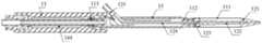
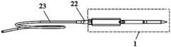
- FIG. 1is a schematic diagram of the structure of the medical implant delivery device of this embodiment
- FIG. 2is a schematic cross-sectional view of the first catheter assembly of this embodiment
- Figure 3is a partial enlarged schematic view of the proximal end of the catheter assembly of this embodiment
- Figure 4is a schematic structural diagram of the first inner tube assembly (excluding the Luer connector) of this embodiment
- Figure 5is a schematic structural diagram of the first catheter assembly of this embodiment
- Fig. 6is a schematic cross-sectional view of Fig. 5;
- Fig. 7is a schematic cross-sectional view of Fig. 6 at the circumferential limit structure
- Figure 8is a schematic structural view of a second inner tube assembly (including a proximal inner tube and a Luer connector) of this embodiment;
- Fig. 9is a schematic cross-sectional view of Fig. 8.
- Figure 10is a front view of the outer tube assembly of this embodiment.
- Figure 11is a schematic cross-sectional view of Figure 10
- Figure 12is a schematic structural diagram of a third inner tube assembly (excluding the proximal inner tube) of this embodiment.
- Figure 13is a schematic cross-sectional view of a third catheter assembly of this embodiment.
- Figure 15is a schematic cross-sectional view of Figure 14;
- Figure 16is a front view of the transmission assembly of this embodiment.
- Figure 17is a schematic cross-sectional view of the transmission assembly of this embodiment.
- Figure 18is a schematic diagram of the assembly of the housing and the stabilizing tube of this embodiment.
- Figure 19is a schematic diagram of the assembly of the catheter assembly and the drive shaft of this embodiment.
- FIG. 20is a half-sectional perspective view of the connection between the catheter assembly and the transmission shaft in FIG. 19;
- Figure 21is a schematic half-sectional plan view of the connection between the catheter assembly and the drive shaft in Figure 19;
- Figure 22is a schematic diagram of the handle of this embodiment.
- Figure 23is a half-sectional perspective view of the assembly of the handle and the transmission shaft in this embodiment.
- the reference signsare as follows:
- the embodiment of the present inventionprovides a delivery device for a medical implant.
- the present inventionwill be further described in detail with reference to the drawings and specific embodiments. According to the following description, the advantages and features of the present invention will be clearer. It should be noted that the drawings all adopt a very simplified form and use imprecise proportions, which are only used to conveniently and clearly assist in explaining the purpose of the embodiments of the present invention.
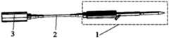
- FIG 1is a schematic structural diagram of a medical implant delivery device of this embodiment; as shown in Figure 1, an embodiment of the present invention provides a medical implant delivery device, and the medical implant delivery device is
- the split structureincludes: a handle 3 and a catheter assembly 1 that are separated from each other, and the handle 3 and the catheter assembly 1 are connected by a transmission shaft 2.
- the delivery deviceis a structure in which the split handle 3 and the catheter assembly 1 are separated from each other.
- the handle 3 and the catheter assembly 1are not in the same packaging shell, and they are independent of each other, and have their own shells and internal components.
- the connection mode of the transmission shaft 2 and the catheter assembly 1can be a detachable connection or a fixed connection, which can be configured according to actual needs.
- the catheter assembly 1includes an inner tube assembly and an outer tube assembly sleeved outside the inner tube assembly.
- the handle 3drives the transmission shaft 2 to rotate so that the outer tube assembly generates relative to the inner tube assembly.
- the end where the catheter assembly 1 is locatedis defined as the distal end
- the end where the handle 3 is locatedis defined as the proximal end.
- the outer tube assembly and the inner tube assemblyare coaxial, the axial direction herein is a direction parallel to the axis of the outer tube assembly (or inner tube assembly), and the circumferential direction is the circumference in a plane perpendicular to the axial direction. direction.
- the catheter assembly 1is used for loading, transporting and releasing medical implants; the transmission shaft 2 is used for transmitting the movement signal from the handle 3 to the catheter assembly 1 during the stages of loading, releasing and recovering the medical implants.
- the handle 3is used to provide power during the stages of loading, releasing, and recovering medical implants, and to control the catheter assembly 1 through the transmission shaft 2.
- the medical implant delivery devicehas a split structure and includes a handle 3 and a catheter assembly 1 that are separated from each other.
- the operatorcan realize the positioning and position adjustment of the medical implant by moving only the catheter assembly 1 .
- the catheter assemblyis lighter in weight and smaller in size and can be moved more conveniently and flexibly, which is more conducive to positioning and fine adjustment of the position during the operation, and improves the stability, precision and accuracy of the operation. It realizes high-quality implantation of medical implants; moreover, the impact of vibration and/or movement of the handle on the catheter assembly is avoided, which further improves the stability and improves the quality of the operation.
- the transmission shaft 2 and the catheter assembly 1are detachably connected, so that the transmission shaft 2 and the catheter assembly 1 can be detached or connected according to requirements.
- the medical implantwhen the medical implant is loaded in vitro, the two are connected; after the medical implant is loaded, the medical implant is separated before the medical implant is released to the diseased location.
- the catheter assembly 1is used alone, which is more conducive to positioning and fine-tuning The position improves the accuracy and stability; when the medical implant is released or recovered, the two are connected, and the release or recovery of the medical implant can be realized through the control handle 3.
- the detachable connection between the transmission shaft 2 and the duct assembly 1improves the simplicity of packaging and transportation.
- the transmission shaft 2 and the handle 3do not directly contact human tissues, and can be reused, saving resources.
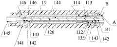
- the catheter assembly 1includes an outer tube assembly 11, an inner tube assembly 12, a housing 13 and a transmission assembly 14.
- the outer tube assembly 11is sleeved outside the inner tube assembly 12, and the transmission assembly 14 is placed in the housing 13.
- the inner tube assembly 12 and the housing 13are relatively stationary, and the outer tube assembly 11 is driven by the handle 3 to move axially relative to the inner tube assembly 12.
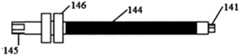
- the transmission assembly 14includes a screw 144, a screw nut 113, and a first bearing 146.
- the first bearingThe outer ring of 146 is embedded and fixed on the proximal end of the housing 13, the inner ring of the first bearing 146 is sleeved and fixed on the proximal end of the screw 144, the screw 144 and the screw nut 113 Meshed, the screw nut 113 is fixedly connected to the outer tube assembly 11, when the transmission shaft and the catheter assembly are in a connected state, the transmission shaft 2 is fixedly connected to the screw rod 144, and the transmission shaft 2 Rotation drives the screw 144 to rotate, which in turn drives the screw nut 113 and the outer tube assembly 11 to move in the axial direction.
- FIG. 4is a schematic diagram of the structure of the first inner tube assembly (excluding the Luer connector) of this embodiment;
- FIG. 5is a schematic view of the structure of the first catheter component of this embodiment;
- FIG. 6is a schematic cross-sectional view of FIG. 5;
- 7is a schematic cross-sectional view of FIG. 6 at the circumferential limit structure.
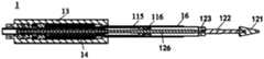
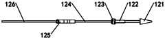
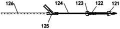
- the inner tube assembly 12includes: a tapered head 121, a distal inner tube 122, a fixed head 123, and a proximal inner tube 126 connected in sequence.
- the outer tube assemblyincludes a sheath tube and a first outer tube 115 connected to the proximal end of the sheath tube, and the proximal end of the first outer tube 115 is fixedly connected to the screw nut.
- the inner wall of the first outer tube 115is provided with a circumferential limiting structure 116, and the outer wall of the proximal inner tube 126 matches the circumferential limiting structure 116 to limit the circumferential direction of the proximal inner tube 126 Spin.
- the catheter assembly 1further includes a first stabilizing tube 16, the proximal end of the first stabilizing tube 16 is fixedly connected to the distal end of the housing 13, and the first outer tube 115 is sleeved on the first stabilizing tube. Tube 16.
- the inner tube assembly of this embodimentmay be a solid tube, which may be integrally formed, or may be separately manufactured and connected by welding or bonding. Processing and manufacturing are more convenient. The emptying design of the outer tube can be set according to actual needs.
- Fig. 8is a schematic structural view of a second inner tube assembly (including a proximal inner tube and a Luer connector) of this embodiment;
- Fig. 9is a schematic cross-sectional view of Fig. 8;
- Fig. 10is a front view of the outer tube assembly of this embodiment
- Figure 11is a schematic cross-sectional view of Figure 10.
- the inner tube assemblyfurther includes an intermediate inner tube 124 and a Luer connector 125.
- the Luer connector 125has a protruding end, from the distal end to the proximal end the tapered head 121,
- the distal inner tube 122, the fixed head 123, the middle inner tube 124, the Luer connector 125, and the proximal inner tube 126are fixedly connected in sequence.
- the outer tube assemblyincludes: a sheath tube 111, a second outer tube 112 fixedly connected to the proximal end of the sheath tube 111, and the proximal end of the second outer tube 112 is fixed to the screw nut 113
- the second outer tube 112is provided with a first strip-shaped opening along the axial direction, wherein the sheath tube 111 is used to cover the medical implant sleeved on the distal inner tube 122.
- Figure 4 and Figure 9in the structure of the two inner tube assemblies shown in Figures 4 and 9, both include a proximal inner tube 126, and the proximal inner tube 126 can be placed in the screw 144 , And the axial limit of the proximal inner tube 126 is realized by the screw rod 144, thereby realizing the axial limit of the inner tube assembly.
- This embodimentskillfully utilizes the inner cavity space of the screw rod 144, reduces the volume of the catheter assembly 1, and makes the catheter assembly 1 more compact, which is more conducive to holding, moving and positioning.
- the transmission assembly 14not only includes a screw rod 144, a screw nut 113, and a first bearing 146, but also includes a second bearing 142.
- the screw rod 144is provided with a through hole in the axial direction.
- the proximal inner tube 126passes through the through hole, and the proximal inner tube 126 is in clearance fit with the through hole, so that during the rotation of the screw rod 144, the inner wall of the screw rod 144 and the inner wall of the proximal end The outer wall of the tube 126 does not interfere; the two ends of the proximal inner tube 126 are respectively sleeved and fixed with a second bearing 142, and the side of the second bearing 142 away from the screw rod 144 is provided with an inner tube fixing nut 141, so The inner tube fixing nut 141 is screwed and fixed to the proximal inner tube 126 to limit the axial movement of the second bearing 142.
- the inner ring of the second bearing 142is fixed on the proximal inner tube 126, the outer ring of the second bearing 142 is fixed to the inner walls of both ends of the screw rod 144, and the inner ring of the first bearing 146 is sleeved and fixed.
- the second bearing 142is, for example, a deep groove ball bearing, and the first bearing 146 is, for example, an angular contact bearing.
- the screw nut 113is fixedly connected to the outer tube assembly. Specifically, the screw nut 113 is fixedly connected to the proximal end A of the outer tube.
- the distal end of the housing 13is fixedly connected to the proximal end B of the stabilizing tube.
- the outer ring of the first bearing 146is fixed on the housing 13
- the inner ring of the first bearing 146is fixed on the outer wall of the proximal end of the screw rod 144
- the outer rings of the second bearing 142are respectively fixed on the screw rod.
- the inner wall of the proximal end and the inner wall of the distal end of 144, the inner ring of the second bearing 142is fixed on the proximal inner tube 126, so that the proximal inner tube 126 is restricted from moving in the axial direction, and the screw 144 is at the same time Being fixed in the axial direction, the screw rod 144 can rotate in the circumferential direction to drive the screw nut 113 to move axially, so that the entire outer tube assembly 11 is moved axially.
- Figure 12is a schematic view of the structure of the third inner tube assembly (excluding the proximal inner tube) of this embodiment;
- Figure 13is a schematic view of the appearance of the third catheter assembly of this embodiment; shown in Figures 4 and 9
- Both of the structures of the two inner tube assembliesinclude a proximal inner tube 126.
- the inner tube assembly of the embodiment of the present inventionmay not include the proximal inner tube 126.
- the inner tube assembly 12includes from the distal end to the proximal end: a tapered head 121, a distal inner tube 122, a fixed head 123, a middle inner tube 124, and a Luer connector 125 connected in sequence.
- the Luer connector 125has an extended end.
- the protruding end of the Luer connector 125can be fixed on the housing 13 or the second stabilizing tube 15, and the inner tube assembly 12 can be fixed by the Luer connector 125.
- the protruding end of the Luer connector 125is fixed to the proximal end of the second strip-shaped opening on the second stabilizing tube 15, and the fixing method can be welding or adhesion; or, the protruding end of the Luer connector 125 It is fixed on the housing 13, and the fixing method can be welding or snapping, which can be selected by those skilled in the art according to the actual situation.
- the inner tube assembly shown in FIGS. 9 and 12includes a Luer connector 125, and an outer tube assembly that matches the Luer connector 125 can be configured.
- an outer tube assembly that matches the Luer connector 125can be configured.
- the outer tube assembly in FIGS. 10 and 11such as outer tube
- the second outer tube 112 in the assemblyis provided with a first strip-shaped opening along the axial direction, and the protruding end of the Luer joint protrudes from the first strip-shaped opening, which will not be repeated here.
- FIG. 14is a schematic diagram of the appearance of the second type of catheter assembly of this embodiment;
- FIG. 15is a schematic cross-sectional view of FIG. 14; as shown in FIGS. 13 and 15, in the second type of catheter assembly and the third type of catheter assembly, both include
- the second stabilizing tube 15, the proximal end of the second stabilizing tube 15is fixedly connected to the distal end of the housing 13, the second outer tube 112 is sleeved in the second stabilizing tube 15, and the first
- the two stabilizing tubes 15have a second strip-shaped opening in the axial direction, and the second strip-shaped opening is arranged corresponding to the first strip-shaped opening, and the protruding end of the Luer street 125 extends from the second strip-shaped opening. Reach out.
- the second stabilizing tube 15supports the second outer tube 112 and also prevents the operator from directly contacting the outer tube assembly.
- the housing 13 and the second stabilizing tube 15support the entire medical implant delivery device, which not only facilitates the pushing of the delivery device, but also improves the release stability of the medical implant (such as a valve).
- Figure 16is a front view of the transmission assembly of this embodiment
- Figure 17is a schematic cross-sectional view of the transmission assembly of this embodiment; as shown in Figure 1, Figure 3, Figure 15 to Figure 17, the role of the transmission assembly is to transmit movement, namely The movement of the transmission shaft 2 is received, and the circumferential movement of the transmission shaft 2 is converted into the axial movement of the outer tube assembly 11.
- This embodimentskillfully utilizes the inner cavity space of the screw rod 144, reduces the volume of the catheter assembly 1, and makes the catheter assembly 1 more compact, which is more conducive to holding, moving and positioning.
- the middle of the screw rod 144is threaded, and the two ends (the proximal end and the distal end) of the screw rod 144 are not threaded for mounting bearings.
- the unthreaded part of the screw rod 144can be the same as the threaded part in the middle of the screw rod. It is a one-piece structure or a split structure.
- the non-threaded parts of the two ends (proximal end and distal end) of the screw rod 144are, for example, the screw rod fixing seat 143, which is fixedly connected to the screw rod 144, and the outer part of the second bearing 142
- the ringis fixed on the inner wall of the screw fixing seat 143, and the screw fixing seat 143 at the proximal end is connected and fixed with the flexible shaft fixing seat 145, which can be fixedly connected by welding or adhesion, for example.
- the other end of the flexible shaft fixing seat 145is used to connect with the transmission shaft 2 to receive the movement of the transmission shaft 2 and convert it into the self-rotating movement of the screw rod 144.
- the flexible shaft fixing base 145 and the screw fixing base 143can be made separately or as an integral structure.
- the flexible shaft fixing base 145 and the screw fixing base 143can also be made into a screw 144 with the threaded section of the screw 144.
- the inner ring of the first bearing 146is sleeved and fixed on the outer wall of the proximal end of the screw rod 144 (that is, the outer wall of the flexible shaft fixing seat 145).
- the catheter assembly 1further includes a circumferential limit block 114, the circumferential limit block 114 is fixedly connected to the nut 113, and the circumferential limit block 114 cooperates with the housing 13 to form a circumference To limit but axially movable structure.
- the sheath tube 111, the second outer tube 112, the screw nut 113, and the circumferential limit block 114are fixedly connected in sequence, and the screw nut 113 is engaged with the screw 144 to make the entire outer tube
- the tube assembly 11can be driven by the screw rod 144 to move axially.
- the circumferential limiting block 114defines the freedom of rotation of the outer tube assembly 11 by the shape matching with the inner surface of the housing 13, so that the outer tube assembly 11 and the housing 13 are kept in circumferential locking and axially movable.
- the circumferential limiting block 114 and the screw nut 113can be fixedly connected by welding or bonding, can be integrally formed, or can be connected separately.
- Figure 18is a schematic diagram of the assembly of the housing and the stabilizing tube of this embodiment; as shown in conjunction with Figures 2 to 7, the outer ring of the first bearing 146 is fixed on the housing 13, and the inner ring of the first bearing 146 is fixed on the screw rod 144, the outer ring of the second bearing 142 is fixed on the proximal inner wall and the distal inner wall of the screw 144, and the inner ring of the second bearing 142 is fixed on the proximal inner tube 126, so The proximal inner tube 126 is restricted from moving in the axial direction. The distal end of the proximal inner tube 126 is fixedly connected to the proximal end of the Luer connector 125.
- the protruding end of the Luer connector 125protrudes from the first strip opening of the second outer tube 112 and the second strip opening of the second stabilizing tube 15, locking the proximal inner tube 126 and the middle inner tube 124 cannot rotate circumferentially.
- the axial and circumferential directions of the proximal inner tube 126are restricted, thereby limiting the six degrees of freedom of the inner tube assembly 12 for fixing medical implants (such as valve stents).
- the housing 13further includes a housing bushing 133, the housing bushing 133 is fixed in the housing 13, and the second outer tube 112 is sleeved in the housing bushing 133
- the housing bushing 133is preferably a low-friction material.
- the housing bushing 133is beneficial to the stability of the second outer tube 112 during the axial movement, and at the same time reduces the frictional resistance.
- the second outer tube 112is in close contact with the housing bushing 133, and the radial movement of the second outer tube 112 is further restricted. On the other hand, it can also prevent the second outer tube 112 from being worn out.
- Figure 19is a schematic diagram of the assembly of the catheter assembly and the drive shaft in this embodiment
- Figure 20is a half-sectional perspective view of the connection between the catheter assembly and the drive shaft in Figure 19
- Figure 21is a half-sectional view of the junction of the catheter assembly and the drive shaft in Figure 19 Schematic plan view.
- the transmission shaft 2functions to transmit the driving force of the handle 3, and transmits the movement signal sent by the handle 3 to the catheter assembly 1.
- the transmission shaft 2includes a transmission flexible shaft, which can be wound, which saves packaging space and also reduces the space occupied during the operation.
- the transmission shaft 2also includes a connecting portion 22 and a transmission flexible shaft outer tube 23.
- the transmission soft shaft 21is a shaft with low rigidity, elasticity and freely bendable transmission. It is used to connect two shafts with different axes and not in the same direction or with relative motion to transmit rotational motion and torque. It can flexibly transfer rotational motion and torque. Transmit.
- the length of the transmission flexible shaft 21can be set according to actual needs, and it can transmit circumferential motion regardless of its length; more preferably, it can rotate in the forward and reverse directions; it can be a solid material or It can be a hollow lumen.
- the transmission soft shaft 21has the following characteristics: 2 to 4 layers of spiral structure, more preferably a double layer spiral structure, the spiral direction is opposite, there is no pitch, the single spiral material is wire or rope; the material is metal material , Such as stainless steel, nickel-titanium alloy, etc.; the spiral outer diameter size range: greater than or equal to 0.1mm; more preferably, greater than or equal to 4mm to match the size of the transmission assembly 14 to minimize the energy loss during the transmission process.
- the connecting portion 22is used to connect the transmission flexible shaft 21 with the flexible shaft fixing seat 145 of the transmission assembly 14, and is more preferably a detachable connection.
- the transmission flexible shaft 21is arranged in the transmission flexible shaft outer tube 23, and the transmission flexible shaft outer tube 23 is used to protect the transmission flexible shaft 21 and is convenient for the operator to grasp.
- the transmission shaft 2 and the catheter assembly 1can be detachably connected, for example, the connecting portion 22 and the flexible shaft fixing seat 145 can be connected in a snap-fit manner, at this time, one end of the connecting portion 22 and The transmission flexible shaft 21 is connected, and the other end of the connecting portion 22 is connected with the flexible shaft fixing seat 145.
- the connection mode of the connecting portion 22 and the transmission flexible shaft 21can be any one or a combination of two or more of clamping, bonding or welding. In order to facilitate processing and assembly, for example, a clamping form is adopted.
- the transmission flexible shaft 21The distal end has a structure with a non-circular surface, and the connecting portion 22 has an inner surface of a corresponding shape, and the two form a snap fit to achieve fixation.
- the connection between the connecting part 22 and the flexible shaft fixing seat 145is preferably a detachable connection, more preferably a snap-fit connection.
- the distal end of the connecting part 22has an inner surface that matches the shape of the outer surface of the flexible shaft fixing seat 145, and the two form For snapping, when connection is needed, the flexible shaft fixing base 145 can be snapped into the distal end of the connecting portion 22.
- the transmission shaft 2also includes a fixing part, which includes a first fixing part 241 connected to the transmission flexible shaft outer tube 23, and a housing 132
- the second fixed part 242is connected.
- the second fixing member 242is connected to the housing 132 by means of a screw thread, a locking groove, and the like.
- the second fixing part 242, the first fixing part 241, and the transmission flexible shaft outer tube 23are connected in sequence and sleeved on the surface of the transmission flexible shaft 21.
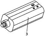
- FIG. 22is a schematic diagram of the handle of this embodiment
- FIG. 23is a half-sectional perspective view of the assembly of the handle and the transmission shaft of this embodiment.
- the handle 3 of the embodiment of the present inventionmay adopt any one of a manual handle, an electric handle, and a hybrid electric and manual drive handle.
- a driving mechanismis provided in the handle 3.
- the driving mechanismis connected with the transmission shaft 2 to drive the circumferential movement of the transmission shaft 2, and the transmission shaft 2 transmits the rotational torque to the catheter assembly
- the transmission assembly 14 in 1 and finally the entire outer tube assembly 11is driven for axial movement, so as to realize the loading and release of the medical implant.
- the handle 3generates circumferential driving force manually or electrically
- the transmission shaft 2transmits the circumferential rotation angle in a certain length of the transmission soft shaft 1:1
- the rotation torque 1:1is transmitted to the catheter Assembly 1, the ability of the catheter assembly 1 to convert circumferential rotation into axial movement, thereby realizing the separation of driving force and moving parts.
- the handle 3 and the transmission shaft 2can be fixedly connected or detachably connected.
- This embodimentdiscloses a delivery device for medical implants, which can solve the problem that the delivery and positioning of medical implants (such as interventional valves) is not flexible enough, and realize the effectiveness of medical implants (such as interventional valves) in the body. Positioning improves the accuracy of the operation, and at the same time can shorten the operation time and improve the quality of the operation.
- the handledrives the bearing to drive the rotation of the flexible shaft movable parts by electric drive or manual drive, so that the screw rod drives the outer tube and the sheath to move axially relative to the inner tube assembly, so as to realize the treatment of medical implants (such as valve stents)
- the specific process of loading and releasing operationsis as follows.
- the transmission shaft 2 and the handle 3are in a connected state in the following stages.
- Valve loading processconnect the drive shaft 2 with the catheter assembly 1, specifically connecting the connecting portion 22 with the flexible shaft fixing seat 145, and the drive handle 3 makes the drive shaft 2 drive the screw rod 144, and then the second outer tube 112 and the sheath tube
- the whole 111moves to the proximal end until the groove of the fixed head 123 is exposed.
- the two hanging ears of the medical implantsuch as a self-expanding stent valve
- the stentis stabilized with the aid of an auxiliary loading tool
- the second outer tube 112is driven to move distally, and the valve stent is pressed and held.
- the valve stentis loaded, and then the drive shaft 2 and the catheter assembly 1 are disassembled, so that the catheter assembly 1 is in a separated state.
- Valve delivery processextend the distal end of the separated catheter assembly 1 along the guide wire into the puncture port and enter the human body. Along the transapical passage, the distal part of the catheter assembly 1 is delivered to the lesion location and adjusted to a suitable angle.
- Valve release processconnect the drive shaft 2 to the catheter assembly 1, and after reconfirming the angle of the sheath tube 111, drive the handle 3 so that the drive shaft 2 drives the screw rod 144, which in turn makes the second outer tube 112 and the sheath tube 111 move proximally , Start to release the valve stent until the valve stent is completely released to the specified position and is out of the delivery system. Specifically, when the sheath tube 111 moves to the proximal end, the valve stent is slowly released until the distal end of the sheath tube 111 moves to the fixed head 123, exposing the groove of the fixed head 123, and the valve stent is completely released.
- the embodiment of the present inventiondescribes the delivery and release process of the valve.
- the set of release and recovery device disclosed in the present inventionis not only used for the delivery of heart valves, but also can be used for the delivery of other valves.
- the present inventionis not limited to one way of delivering heart valves.
- the medical implant delivery devicehas a split structure, including: a handle and a catheter assembly that are separated from each other, which reduces the mass of the traditional catheter assembly.
- the operatorcan move the catheter assembly to achieve the medical implant Positioning and position adjustment.
- the catheter assemblyis lighter in weight and smaller in size, and can be moved more conveniently and flexibly. It is more conducive to positioning and fine-tuning the position during the operation, improving the stability and accuracy of the operation process, and achieving
- the medical implantis implanted with high quality; moreover, the impact of the vibration and/or movement of the handle on the catheter assembly is avoided, and the stability and the quality of the operation are further improved.
- the drive shaft and the catheter assemblyare detachably connected, which improves the convenience in the process of loading, transporting and releasing the medical implant, and the detachable connection also improves the convenience of packaging and transportation.
- the transmission shaftis a transmission flexible shaft, and the transmission flexible shaft can be wound, which saves packaging space and reduces the space occupied during surgery.
- the screw rodis provided with a through hole in the axial direction, and the proximal inner tube passes through the through hole, which cleverly utilizes the inner cavity space of the screw rod, reduces the volume of the catheter assembly, and makes the catheter assembly smaller and more compact. Conducive to holding, moving and positioning.
- this embodimentcan achieve sensitive and effective adjustment in the positioning ability of the conveying device.
- the delivery device provided in this embodimentcan realize the accurate release of the medical implant (for example, the artificial valve) at the diseased location, ensure the quality of the release, and shorten the operation time.
Landscapes
- Health & Medical Sciences (AREA)
- Cardiology (AREA)
- Engineering & Computer Science (AREA)
- Biomedical Technology (AREA)
- Heart & Thoracic Surgery (AREA)
- Transplantation (AREA)
- Oral & Maxillofacial Surgery (AREA)
- Vascular Medicine (AREA)
- Life Sciences & Earth Sciences (AREA)
- Animal Behavior & Ethology (AREA)
- General Health & Medical Sciences (AREA)
- Public Health (AREA)
- Veterinary Medicine (AREA)
- Media Introduction/Drainage Providing Device (AREA)
- Prostheses (AREA)
Abstract
Description
Translated fromChinese本发明属于医用手术设备领域,具体涉及一种医用植入物的输送装置。The invention belongs to the field of medical surgical equipment, and in particular relates to a conveying device for medical implants.
经心尖入路是心脏外科手术的常用通路,由于体表切口距离目标瓣膜位置很近,约10cm以下,且体表伤口、心脏穿刺点与瓣环中心三者的同轴性好,通常输送装置会采用整体硬质的直管设计,使术者对角度、深度的调整更灵敏、直观。The transapical approach is a common approach for cardiac surgery. Because the body surface incision is very close to the target valve position, about 10cm or less, and the body surface wound, the heart puncture point and the center of the valve ring have good coaxiality, usually the delivery device The overall rigid straight tube design will be used to make the adjustment of the angle and depth more sensitive and intuitive.
TAVI(经导管主动脉瓣植入术)、TMVR(经导管二尖瓣置换术)等瓣膜置换手术都会采用经心尖的入路,且这些置换手术对释放精准程度的要求都很高,在假体释放前、释放中、回收、再释放都需要实时的位置保持与位置微调。因为现有的输送装置体积大、质量重,手持整个输送装置操作时比较笨重、且稳定性差,所以在手术中,常用的器械定位和稳定手段为增添一个输送系统的托架系统,一端固定在手术床上,一端夹持输送装置手柄,从而满足输送装置在手术过程中定位、稳定的需求。TAVI (transcatheter aortic valve implantation), TMVR (transcatheter mitral valve replacement) and other valve replacement surgeries will use transapical approach, and these replacement surgeries have high requirements for release accuracy. Real-time position retention and fine adjustment of position are required before body release, during release, recovery, and re-release. Because the existing delivery device is large in size and heavy in weight, the entire delivery device is relatively cumbersome and has poor stability during operation. Therefore, the commonly used device positioning and stabilization method during surgery is to add a delivery system bracket system, one end is fixed at On the operating bed, one end clamps the handle of the delivery device to meet the needs of positioning and stability of the delivery device during the operation.
然而,托架系统需要提供稳固的支撑力,并满足多个维度的自由度,所以通常来说托架自重都偏重,体积也较大,会在一定程度上延长手术时间,具体原因如下:However, the bracket system needs to provide a stable supporting force and satisfy multiple degrees of freedom. Therefore, the bracket is usually heavy and bulky, which will extend the operation time to a certain extent. The specific reasons are as follows:
1.操作步骤多,涉及组建托架、调整托架、固定托架等;1. There are many operating steps, involving building brackets, adjusting brackets, fixing brackets, etc.;
2.手术过程中,托架的操作复杂性程度也可能会影响手术时长;2. During the operation, the complexity of the operation of the bracket may also affect the length of the operation;
3.托架体积一般较大,影响其他操作的简便性;3. The size of the bracket is generally large, which affects the ease of other operations;
针对以上缺点,需要一种输送装置,可实时根据需求调整释放位置,既能精确地将假体释放到目标位置,又能尽可能地缩短调整输送装置位置的时间进而缩短手术时间,实现高质量地置换瓣膜。In view of the above shortcomings, a delivery device is needed that can adjust the release position according to requirements in real time, which can accurately release the prosthesis to the target position, but also shorten the time for adjusting the position of the delivery device as much as possible to shorten the operation time and achieve high quality Replace the valve.
发明内容Summary of the invention
本发明的目的在于提供一种医用植入物的输送装置,便于医用植入物的 定位和位置调整,提高医用植入物手术过程操作精准度和准确性,提高输送装置的稳定性。The purpose of the present invention is to provide a medical implant delivery device, which facilitates the positioning and position adjustment of the medical implant, improves the operation precision and accuracy of the medical implant operation process, and improves the stability of the delivery device.
本发明提供一种医用植入物的输送装置,所述医用植入物的输送装置具有分体式结构,包括:相互分离的手柄和导管组件,所述手柄和所述导管组件通过传动轴连接。The present invention provides a medical implant delivery device. The medical implant delivery device has a split structure and includes a handle and a catheter assembly that are separated from each other, and the handle and the catheter assembly are connected by a drive shaft.
进一步的,所述传动轴与所述导管组件可拆卸连接。Further, the transmission shaft is detachably connected to the catheter assembly.
进一步的,所述导管组件包括内管组件和套设于所述内管组件外的外管组件,所述手柄带动所述传动轴旋转使所述外管组件产生相对于所述内管组件的轴向移动。Further, the catheter assembly includes an inner tube assembly and an outer tube assembly sleeved outside the inner tube assembly, and the handle drives the transmission shaft to rotate to cause the outer tube assembly to generate an offset relative to the inner tube assembly. Axial movement.
进一步的,所述导管组件还包括传动组件,所述传动组件包括丝杆和丝杆螺母,所述丝杆和所述丝杆螺母啮合,所述丝杆螺母与所述外管组件固定连接,所述传动轴与所述导管组件处于连接状态时,所述传动轴与所述丝杆连接,所述传动轴旋转带动所述丝杆旋转,进而带动所述丝杆螺母和所述外管组件沿轴向移动。Further, the catheter assembly further includes a transmission assembly, the transmission assembly includes a screw rod and a screw nut, the screw rod is engaged with the screw nut, and the screw nut is fixedly connected to the outer tube assembly, When the transmission shaft and the catheter assembly are in a connected state, the transmission shaft is connected with the screw rod, and the rotation of the transmission shaft drives the screw rod to rotate, thereby driving the screw nut and the outer tube assembly Move along the axis.
进一步的,所述导管组件还包括壳体,所述传动组件还包括第一轴承,所述第一轴承的外圈嵌设固定在所述壳体的近端,所述第一轴承的内圈套设固定在所述丝杆的近端。Further, the catheter assembly further includes a housing, the transmission assembly further includes a first bearing, the outer ring of the first bearing is embedded and fixed to the proximal end of the housing, and the inner ring of the first bearing It is fixed at the proximal end of the screw rod.
进一步的,所述内管组件从远端到近端包括:依次连接的锥形头、远端内管、固定头和近端内管。Further, from the distal end to the proximal end, the inner tube assembly includes: a tapered head, a distal inner tube, a fixed head, and a proximal inner tube connected in sequence.
进一步的,所述外管组件包括:鞘管以及与所述鞘管近端相连的第一外管,所述第一外管近端与所述丝杆螺母固定连接。Further, the outer tube assembly includes a sheath tube and a first outer tube connected to the proximal end of the sheath tube, and the proximal end of the first outer tube is fixedly connected to the screw nut.
进一步的,所述第一外管的内壁设置有周向限位结构,所述近端内管的外壁与所述周向限位结构匹配,以限制所述近端内管周向旋转。Further, the inner wall of the first outer tube is provided with a circumferential limiting structure, and the outer wall of the proximal inner tube matches the circumferential limiting structure to limit the circumferential rotation of the proximal inner tube.
进一步的,所述导管组件还包括第一稳定管,所述第一稳定管的近端与所述壳体的远端固定连接,所述第一外管套设在所述第一稳定管中。Further, the catheter assembly further includes a first stabilizing tube, the proximal end of the first stabilizing tube is fixedly connected to the distal end of the housing, and the first outer tube is sleeved in the first stabilizing tube .
进一步的,所述内管组件还包括中间内管和鲁尔接头,所述鲁尔接头具有伸出端,从远端到近端所述锥形头、所述远端内管、所述固定头、所述中间内管、所述鲁尔接头和所述近端内管依次连接。Further, the inner tube assembly further includes an intermediate inner tube and a Luer connector, the Luer connector has an extended end, from the distal end to the proximal end, the tapered head, the distal inner tube, and the fixing The head, the middle inner tube, the Luer connector and the proximal inner tube are connected in sequence.
进一步的,所述传动组件还包括两个第二轴承,所述丝杆沿轴向设置有贯通孔,所述近端内管穿过所述贯通孔,所述近端内管与所述贯通孔间隙配合,所述近端内管的两端分别套设固定一个所述第二轴承,每个所述第二轴承的外圈固定于所述丝杆的端部内壁,所述第一轴承的内圈套设固定在所述丝杆的近端外壁。Further, the transmission assembly further includes two second bearings, the screw rod is provided with a through hole in the axial direction, the proximal inner tube passes through the through hole, and the proximal inner tube communicates with the through hole. The two ends of the proximal inner tube are respectively sleeved and fixed with a second bearing, the outer ring of each second bearing is fixed to the inner wall of the end of the screw rod, and the first bearing The inner ring is sleeved and fixed on the outer wall of the proximal end of the screw rod.
进一步的,所述内管组件从远端到近端包括:依次连接的锥形头、远端内管、固定头、中间内管和鲁尔接头,所述鲁尔接头具有伸出端。Further, from the distal end to the proximal end, the inner tube assembly includes: a tapered head, a distal inner tube, a fixed head, an intermediate inner tube, and a Luer connector connected in sequence, and the Luer connector has an extended end.
进一步的,所述外管组件包括:鞘管以及与所述鞘管近端相连的第二外管,所述第二外管近端与所述丝杆螺母固定连接;所述第二外管沿轴向设置有第一条形开口,所述鲁尔接头的伸出端从所述第一条形开口伸出。Further, the outer tube assembly includes: a sheath tube and a second outer tube connected to the proximal end of the sheath tube, and the proximal end of the second outer tube is fixedly connected to the screw nut; the second outer tube A first strip-shaped opening is provided along the axial direction, and the protruding end of the luer connector protrudes from the first strip-shaped opening.
进一步的,所述导管组件还包括第二稳定管,所述第二稳定管的近端与所述壳体的远端固定连接,所述第二外管套设在所述第二稳定管中,所述第二稳定管沿轴向具有第二条形开口,所述第二条形开口与所述第一条形开口对应设置,所述鲁尔接头的伸出端自所述第一条形开口伸出后从所述第二条形开口伸出。Further, the catheter assembly further includes a second stabilizing tube, the proximal end of the second stabilizing tube is fixedly connected to the distal end of the housing, and the second outer tube is sleeved in the second stabilizing tube , The second stabilizing tube has a second strip-shaped opening in the axial direction, the second strip-shaped opening is arranged corresponding to the first strip-shaped opening, and the protruding end of the luer connector is from the first strip The shaped opening protrudes from the second strip-shaped opening.
进一步的,所述导管组件还包括周向限位块,所述周向限位块与所述丝杆螺母固定连接,所述周向限位块与所述壳体配合,以使所述外管组件与所述壳体保持周向锁定且轴向可移动。Further, the catheter assembly further includes a circumferential limit block, the circumferential limit block is fixedly connected with the screw nut, and the circumferential limit block is matched with the housing to make the outer The pipe assembly and the housing are kept circumferentially locked and axially movable.
进一步的,所述传动轴包括传动软轴。Further, the transmission shaft includes a flexible transmission shaft.
进一步的,所述传动软轴具有2~4层螺旋结构,每层所述螺旋结构的螺旋外径尺寸大于或等于0.1mm,所述传动软轴的材料为金属材料。Further, the transmission flexible shaft has 2 to 4 layers of spiral structures, the spiral outer diameter of each layer of the spiral structure is greater than or equal to 0.1 mm, and the material of the transmission flexible shaft is a metal material.
进一步的,所述传动轴还包括连接部和传动软轴外管,所述传动软轴套设于所述传动软轴外管中,所述传动软轴通过所述连接部与所述导管组件连接。Further, the transmission shaft further includes a connecting portion and a transmission flexible shaft outer tube, the transmission flexible shaft is sleeved in the transmission flexible shaft outer tube, and the transmission flexible shaft is connected to the catheter assembly through the connection portion. connection.
进一步的,所述传动轴与所述导管组件固定连接。Further, the transmission shaft is fixedly connected with the catheter assembly.
与现有技术相比,本发明的技术方案具有以下有益效果:Compared with the prior art, the technical solution of the present invention has the following beneficial effects:
所述医用植入物的输送装置具有分体式结构,包括:相互分离的手柄和 导管组件,相比传统的一体式设计,操作者可通过移动质量轻、体积小的导管组件实现医用植入物的定位和位置调整。相比传统输送系统的整体移动,导管组件质量轻、体积小进而可以使操作更方便、更灵活,更有利于手术过程中定位和位置微调,操作过程中稳定性高,提高了操作精准度和准确性,实现了高质量地植入医用植入物;而且,避免了手柄的震动和/或移动对导管组件的影响,进一步提高了稳定性,提高了手术质量。The medical implant delivery device has a split structure, including: a handle and a catheter assembly separated from each other. Compared with the traditional integrated design, the operator can realize the medical implant by moving the catheter assembly with light weight and small volume. Positioning and position adjustment. Compared with the overall movement of the traditional delivery system, the catheter assembly is lighter in weight and smaller in size, which can make the operation more convenient and flexible, and is more conducive to positioning and fine-tuning of the position during the operation. The stability during the operation is high, and the operation accuracy is improved. Accuracy realizes high-quality implantation of medical implants; moreover, the impact of vibration and/or movement of the handle on the catheter assembly is avoided, which further improves the stability and improves the quality of the operation.
进一步地,所述传动轴与所述导管组件可拆卸连接,提高了装载、输送、释放医用植入物过程中的便捷性,而且可拆卸连接也提高了包装、运输的简便性。Further, the transmission shaft and the catheter assembly are detachably connected, which improves the convenience in the process of loading, transporting and releasing the medical implant, and the detachable connection also improves the convenience of packaging and transportation.
进一步的,所述传动轴为传动软轴,传动软轴可缠绕,节约了包装空间,也减小了手术中所占用的空间。Further, the transmission shaft is a transmission flexible shaft, and the transmission flexible shaft can be wound, which saves packaging space and reduces the space occupied during surgery.
进一步的,所述丝杆沿轴向设置有贯通孔,所述近端内管穿过所述贯通孔,巧妙地利用了丝杆的内腔空间,缩减了导管组件的体积,使得导管组件更加小巧,更有利于持握、移动和定位。Further, the screw rod is provided with a through hole in the axial direction, and the proximal inner tube passes through the through hole, which cleverly utilizes the lumen space of the screw rod, reduces the volume of the catheter assembly, and makes the catheter assembly more Small and exquisite, it is more conducive to holding, moving and positioning.
图1为本实施例的医用植入物的输送装置的结构示意图;FIG. 1 is a schematic diagram of the structure of the medical implant delivery device of this embodiment;
图2为本实施例的第一种导管组件的剖面示意图;2 is a schematic cross-sectional view of the first catheter assembly of this embodiment;
图3为本实施例的导管组件的近端局部放大示意图;Figure 3 is a partial enlarged schematic view of the proximal end of the catheter assembly of this embodiment;
图4为本实施例的第一种内管组件(不含鲁尔接头)的结构示意图;Figure 4 is a schematic structural diagram of the first inner tube assembly (excluding the Luer connector) of this embodiment;
图5为本实施例的第一种导管组件的结构示意图;Figure 5 is a schematic structural diagram of the first catheter assembly of this embodiment;
图6为图5的剖面示意图;Fig. 6 is a schematic cross-sectional view of Fig. 5;
图7为图6在周向限位结构处的横截面示意图;Fig. 7 is a schematic cross-sectional view of Fig. 6 at the circumferential limit structure;
图8为本实施例的第二种内管组件(含近端内管和鲁尔接头)的结构示意图;Figure 8 is a schematic structural view of a second inner tube assembly (including a proximal inner tube and a Luer connector) of this embodiment;
图9为图8的剖面示意图;Fig. 9 is a schematic cross-sectional view of Fig. 8;
图10为本实施例的外管组件的主视图;Figure 10 is a front view of the outer tube assembly of this embodiment;
图11为图10的剖面示意图;Figure 11 is a schematic cross-sectional view of Figure 10;
图12为本实施例的第三种内管组件(不含近端内管)的结构示意图;Figure 12 is a schematic structural diagram of a third inner tube assembly (excluding the proximal inner tube) of this embodiment;
图13为本实施例的第三种导管组件的剖面示意图;Figure 13 is a schematic cross-sectional view of a third catheter assembly of this embodiment;
图14为本实施例的第二种导管组件的外观示意图;14 is a schematic diagram of the appearance of the second catheter assembly of this embodiment;
图15为图14的剖面示意图;Figure 15 is a schematic cross-sectional view of Figure 14;
图16为本实施例的传动组件的主视图;Figure 16 is a front view of the transmission assembly of this embodiment;
图17为本实施例的传动组件的剖面示意图;Figure 17 is a schematic cross-sectional view of the transmission assembly of this embodiment;
图18为本实施例的壳体和稳定管的装配示意图;Figure 18 is a schematic diagram of the assembly of the housing and the stabilizing tube of this embodiment;
图19为本实施例的导管组件与传动轴装配示意图;Figure 19 is a schematic diagram of the assembly of the catheter assembly and the drive shaft of this embodiment;
图20为图19中导管组件与传动轴连接处的半剖立体示意图;20 is a half-sectional perspective view of the connection between the catheter assembly and the transmission shaft in FIG. 19;
图21为图19中导管组件与传动轴连接处的半剖平面示意图;Figure 21 is a schematic half-sectional plan view of the connection between the catheter assembly and the drive shaft in Figure 19;
图22为本实施例的手柄示意图;Figure 22 is a schematic diagram of the handle of this embodiment;
图23为本实施例的手柄与传动轴装配半剖立体示意图。其中,附图标记如下:Figure 23 is a half-sectional perspective view of the assembly of the handle and the transmission shaft in this embodiment. Among them, the reference signs are as follows:
1-导管组件;2-传动轴;3-手柄;11-外管组件;12-内管组件;13-壳体;14-传动组件;111-鞘管;112-第二外管;113-丝杆螺母;114-周向限位块;115-第一外管;121-锥形头;122-远端内管;123-固定头;124-中间内管;125-鲁尔接头;126-近端内管;13-壳体;133-壳体衬套;141-内管固定螺母;142-第二轴承;143-丝杆固定座;144-丝杆;145-软轴固定座;146-第一轴承;15-第二稳定管;21-传动软轴;22-连接部;23-传动软轴外管;241-第一固定部件;242-第二固定部件。1-catheter assembly; 2-drive shaft; 3-handle; 11-outer tube assembly; 12-inner tube assembly; 13-housing; 14-transmission assembly; 111-sheath; 112-second outer tube; 113- Screw nut; 114-circumferential limit block; 115-first outer tube; 121-tapered head; 122-distal inner tube; 123-fixed head; 124-intermediate inner tube; 125-luer connector; 126 -Proximal inner tube; 13-housing; 133-housing bushing; 141-inner tube fixing nut; 142-second bearing; 143-screw fixing seat; 144-screw rod; 145-flexible shaft fixing seat; 146-first bearing; 15-second stabilizer tube; 21-transmission flexible shaft; 22-connection part; 23-transmission flexible shaft outer tube; 241-first fixed part; 242-second fixed part.
本发明实施例提供了一种医用植入物的输送装置。以下结合附图和具体实施例对本发明进一步详细说明。根据下面说明,本发明的优点和特征将更清楚。需要说明的是,附图均采用非常简化的形式且使用非精准的比例,仅用以方便、明晰地辅助说明本发明实施例的目的。The embodiment of the present invention provides a delivery device for a medical implant. Hereinafter, the present invention will be further described in detail with reference to the drawings and specific embodiments. According to the following description, the advantages and features of the present invention will be clearer. It should be noted that the drawings all adopt a very simplified form and use imprecise proportions, which are only used to conveniently and clearly assist in explaining the purpose of the embodiments of the present invention.
图1为本实施例的医用植入物的输送装置的结构示意图;如图1所示,本发明实施例提供了一种医用植入物的输送装置,所述医用植入物的输送装 置为分体式结构,包括:相互分离的手柄3和导管组件1,所述手柄3和所述导管组件1通过传动轴2连接。输送装置为分体式手柄3和导管组件1相互分离的结构,具体指手柄3和导管组件1不在同一封装壳体内,二者相互独立,有各自的壳体及内部组成部分。所述传动轴2与所述导管组件1的连接方式可以为可拆卸连接,也可以为固定连接,根据实际需求配置。具体的,所述导管组件1包括内管组件和套设于所述内管组件外的外管组件,所述手柄3带动所述传动轴2旋转使所述外管组件产生相对于所述内管组件的轴向移动。其中,所述导管组件1所在的一端定义为远端,所述手柄3所在的一端定义为近端。所述外管组件和内管组件同轴,本文中的轴向均为平行于所述外管组件(或内管组件)的轴的方向,周向为在垂直于轴向的平面内的圆周方向。Figure 1 is a schematic structural diagram of a medical implant delivery device of this embodiment; as shown in Figure 1, an embodiment of the present invention provides a medical implant delivery device, and the medical implant delivery device is The split structure includes: a
导管组件1用于装载、运输和释放医用植入物;传动轴2用于在装载、释放、回收医用植入物阶段将手柄3发出的运动信号传递给导管组件1。手柄3用于在装载、释放、回收医用植入物阶段提供动力,通过传动轴2操控导管组件1。The
本实施例中,所述医用植入物的输送装置为分体式结构,包括:相互分离的手柄3和导管组件1,操作者可通过仅移动导管组件1实现医用植入物的定位和位置调整。相比传统输送系统的整体移动,导管组件质量轻、体积小进而可以更方便、更灵活的移动,更有利于手术过程中定位和位置微调,提高了操作过程中的稳定性、精准度和准确性,实现了高质量地植入医用植入物;而且,避免了手柄的震动和/或移动对导管组件的影响,进一步提高了稳定性,提高了手术质量。In this embodiment, the medical implant delivery device has a split structure and includes a
所述传动轴2与所述导管组件1可拆卸连接,如此可根据需求将所述传动轴2与所述导管组件1拆卸或连接。具体地,体外装载医用植入物时,将两者连接;医用植入物装载完成之后释放医用植入物到病变位置之前,将两者分离,导管组件1单独使用,更有利于定位以及微调位置,提高了准确性和稳定性;医用植入物释放或回收时,两者连接,即可通过操控手柄3实现对医用植入物的释放或回收。而且,所述传动轴2与所述导管组件1的可拆 卸连接提高了包装、运输的简便性。此外,传动轴2和手柄3不与人体组织直接接触,可重复利用,节约资源。The
图2为本实施例的第一种导管组件的剖面示意图;如图1和图2所示,导管组件1包括外管组件11、内管组件12、壳体13和传动组件14。所述外管组件11套设于所述内管组件12外,所述传动组件14置于所述壳体13中。本实施例中,内管组件12与壳体13相对静止,外管组件11在手柄3的驱动下相对于内管组件12发生轴向运动。2 is a schematic cross-sectional view of the first catheter assembly of this embodiment; as shown in FIGS. 1 and 2, the
图3为本实施例的导管组件的近端局部放大示意图;如图1至图3所示,所述传动组件14包括丝杆144、丝杆螺母113和第一轴承146,所述第一轴承146的外圈嵌设固定在所述壳体13的近端,所述第一轴承146的内圈套设固定在所述丝杆144的近端,所述丝杆144和所述丝杆螺母113啮合,所述丝杆螺母113与所述外管组件11固定连接,所述传动轴与所述导管组件处于连接状态时,所述传动轴2与所述丝杆144固定连接,所述传动轴2旋转带动所述丝杆144旋转,进而带动所述丝杆螺母113和所述外管组件11沿轴向移动。3 is a partial enlarged schematic view of the proximal end of the catheter assembly of this embodiment; as shown in FIGS. 1 to 3, the
图4为本实施例的第一种内管组件(不含鲁尔接头)的结构示意图;图5为本实施例的第一种导管组件的结构示意图;图6为图5的剖面示意图;图7为图6在周向限位结构处的横截面示意图。如图4至图7所示,所述内管组件12从远端到近端包括:依次连接的锥形头121、远端内管122、固定头123、近端内管126。所述外管组件包括:鞘管以及与所述鞘管近端相连的第一外管115,所述第一外管115近端与所述丝杆螺母固定连接。所述第一外管115的内壁设置有周向限位结构116,所述近端内管126的外壁与所述周向限位结构116匹配,以限制所述近端内管126的周向旋转。所述导管组件1还包括第一稳定管16,所述第一稳定管16的近端与所述壳体13的远端固定连接,所述第一外管115套设在所述第一稳定管16中。本实施例的内管组件可为实心管材,可一体成型,也可分别制造后通过焊接或黏合等方式连接。加工制造更方便。可根据实际需求设置外管的排空设计。4 is a schematic diagram of the structure of the first inner tube assembly (excluding the Luer connector) of this embodiment; FIG. 5 is a schematic view of the structure of the first catheter component of this embodiment; FIG. 6 is a schematic cross-sectional view of FIG. 5; 7 is a schematic cross-sectional view of FIG. 6 at the circumferential limit structure. As shown in FIGS. 4 to 7, from the distal end to the proximal end, the
图8为本实施例的第二种内管组件(含近端内管和鲁尔接头)的结构示 意图;图9为图8的剖面示意图;图10为本实施例的外管组件的主视图;图11为图10的剖面示意图。Fig. 8 is a schematic structural view of a second inner tube assembly (including a proximal inner tube and a Luer connector) of this embodiment; Fig. 9 is a schematic cross-sectional view of Fig. 8; Fig. 10 is a front view of the outer tube assembly of this embodiment Figure 11 is a schematic cross-sectional view of Figure 10.
如图8和图9所示,所述内管组件还包括中间内管124和鲁尔接头125,所述鲁尔接头125具有伸出端,从远端到近端所述锥形头121、远端内管122、固定头123、中间内管124、鲁尔接头125、近端内管126依次固定连接。如图9至图11所示,外管组件包括:鞘管111,与鞘管111近端固定连接的第二外管112,所述第二外管112近端与所述丝杆螺母113固定连接,所述第二外管112沿轴向设置有第一条形开口,其中,鞘管111用于包覆套设在远端内管122上的医用植入物。As shown in Figures 8 and 9, the inner tube assembly further includes an intermediate
结合图3、图4和图9所示,在图4和图9所示的两种内管组件的结构中,均包括近端内管126,近端内管126可置于丝杆144中,且通过丝杆144实现近端内管126的轴向限位,进而实现内管组件的轴向限位。本实施例巧妙地利用了丝杆144的内腔空间,缩减了导管组件1的体积,使得导管组件1更加小巧,更有利于持握、移动和定位。As shown in Figure 3, Figure 4 and Figure 9, in the structure of the two inner tube assemblies shown in Figures 4 and 9, both include a proximal
如图3所示,所述传动组件14除了包括丝杆144、丝杆螺母113、第一轴承146外,还包括第二轴承142,所述丝杆144的内部沿轴向设置有贯通孔,所述近端内管126穿过所述贯通孔,所述近端内管126与所述贯通孔间隙配合,以使所述丝杆144旋转的过程中,丝杆144的内壁和近端内管126的外壁不干涉;所述近端内管126的两端分别套设固定有第二轴承142,所述第二轴承142的远离丝杆144的一侧设置有内管固定螺母141,所述内管固定螺母141与近端内管126螺纹连接固定,用以限制第二轴承142的轴向移动。所述第二轴承142的内圈固定在近端内管126上,所述第二轴承142的外圈固定于所述丝杆144的两端内壁,所述第一轴承146的内圈套设固定在所述丝杆144的近端外壁。第二轴承142例如为深沟滚珠轴承,第一轴承146例如为角接触轴承。所述丝杆螺母113与所述外管组件固定连接,具体的,丝杆螺母113与外管近端A固定连接。壳体13远端与稳定管近端B固定连接。As shown in FIG. 3, the
本实施例中,第一轴承146的外圈固定在壳体13上,第一轴承146的内圈固定在丝杆144的近端外壁,所述第二轴承142的外圈分别固定在丝杆144 的近端内壁和远端内壁,所述第二轴承142的内圈固定在近端内管126上,如此一来近端内管126被限制了轴向上的移动,同时丝杆144在轴向上被固定,丝杆144可以周向旋转进而带动丝杆螺母113轴向运动,使整个外管组件11轴向运动。In this embodiment, the outer ring of the
图12为本实施例的第三种内管组件(不含近端内管)的结构示意图;图13为本实施例的第三种导管组件的外观示意图;在图4和图9所示的两种内管组件的结构中,均包括近端内管126。需要说明的是,本发明实施例的内管组件也可以不包括近端内管126。如图12和图13所示,所述内管组件12从远端到近端包括:依次连接的锥形头121、远端内管122、固定头123、中间内管124、鲁尔接头125,所述鲁尔接头125具有伸出端。所述鲁尔接头125的伸出端可固定在所述壳体13上或第二稳定管15上,通过鲁尔接头125实现内管组件12的固定。具体的,鲁尔接头125的伸出端固定在所述第二稳定管15上的第二条形开口的近端,固定方式可为焊接或黏连;或者,鲁尔接头125的伸出端固定在壳体13上,固定方式可选焊接或卡扣,本领域技术人员可根据实际情况选择。Figure 12 is a schematic view of the structure of the third inner tube assembly (excluding the proximal inner tube) of this embodiment; Figure 13 is a schematic view of the appearance of the third catheter assembly of this embodiment; shown in Figures 4 and 9 Both of the structures of the two inner tube assemblies include a proximal
图9和图12所示的内管组件中均包括鲁尔接头125,可配置与鲁尔接头125匹配的外管组件,具体可参照对图10和图11中外管组件的介绍,例如外管组件中的所述第二外管112沿轴向设置有第一条形开口,所述鲁尔接头的伸出端从所述第一条形开口伸出,在此不再赘述。The inner tube assembly shown in FIGS. 9 and 12 includes a
图14为本实施例的第二种导管组件的外观示意图;图15为图14的剖面示意图;如图13和图15所示,在第二种导管组件和第三种导管组件中,均包括第二稳定管15,所述第二稳定管15的近端与所述壳体13的远端固定连接,所述第二外管112套设在所述第二稳定管15中,所述第二稳定管15沿轴向具有第二条形开口,所述第二条形开口与所述第一条形开口对应设置,所述鲁尔街头125的伸出端从所述第二条形开口伸出。所述第二稳定管15对第二外管112起支撑作用,还避免了操作者直接接触外管组件。壳体13和第二稳定管15对整个医用植入物的输送装置起支撑作用,不但便于输送装置的 推送,而且提高了医用植入物(例如瓣膜)释放的稳定性。14 is a schematic diagram of the appearance of the second type of catheter assembly of this embodiment; FIG. 15 is a schematic cross-sectional view of FIG. 14; as shown in FIGS. 13 and 15, in the second type of catheter assembly and the third type of catheter assembly, both include The second stabilizing
图16为本实施例的传动组件的主视图;图17为本实施例的传动组件的剖面示意图;如图1、图3、图15至图17所示,传动组件的作用为传递运动,即接收传动轴2的运动,将传动轴2的周向运动转化为外管组件11的轴向运动。本实施例巧妙地利用了丝杆144的内腔空间,缩减了导管组件1的体积,使得导管组件1更加小巧,更有利于持握、移动和定位。具体的,丝杆144的中间带螺纹,丝杆144的两端(近端和远端)不带螺纹用于安装轴承,丝杆144的两端不带螺纹部分可以与丝杆中间带螺纹部分为一体结构,也可为分体结构。分体结构时,丝杆144的两端(近端和远端)不带螺纹部分例如为丝杆固定座143,丝杆固定座143与丝杆144固定连接,所述第二轴承142的外圈固定于所述丝杆固定座143的内壁,近端的丝杆固定座143连接固定有软轴固定座145,例如可通过焊接或黏连固定连接。软轴固定座145的另一端用于与传动轴2连接,接收传动轴2的运动,转化为丝杆144的自体旋转运动。软轴固定座145与丝杆固定座143可分体制作,也可以制作为一体结构,软轴固定座145、丝杆固定座143还可以与丝杆144的中间带螺纹段制作为丝杆144一体结构。所述第一轴承146的内圈套设固定在所述丝杆144的近端外壁(即软轴固定座145的外壁)。Figure 16 is a front view of the transmission assembly of this embodiment; Figure 17 is a schematic cross-sectional view of the transmission assembly of this embodiment; as shown in Figure 1, Figure 3, Figure 15 to Figure 17, the role of the transmission assembly is to transmit movement, namely The movement of the
具体的,所述导管组件1还包括周向限位块114,所述周向限位块114与所述螺母113固定连接,所述周向限位块114与所述壳体13配合形成周向限位但轴向可移动结构。导管组件1中,从远端到近端,鞘管111、第二外管112、丝杆螺母113、周向限位块114依次固定连接,丝杆螺母113与丝杆144啮合,使整个外管组件11可被丝杆144驱动轴向运动。周向限位块114通过与壳体13的内表面的形状配合限定了外管组件11自身旋转的自由度,使外管组件11与壳体13保持周向锁定且轴向可移动。周向限位块114与丝杆螺母113固定连接方式可焊接或黏连、可一体成型,也可分离连接。Specifically, the
图18为本实施例的壳体和稳定管的装配示意图;结合图2至图7所示,第一轴承146的外圈固定在壳体13上,第一轴承146的内圈固定在丝杆144的近端外壁,所述第二轴承142的外圈分别固定在丝杆144的近端内壁和远 端内壁,所述第二轴承142的内圈固定在近端内管126上,如此一来近端内管126被限制了轴向上的移动。所述近端内管126的远端与所述鲁尔接头125的近端固定连接。所述鲁尔接头125的伸出端从所述第二外管112的第一条形开口和第二稳定管15的第二条形开口伸出,锁定了近端内管126和中间内管124无法周向旋转,如此一来近端内管126的轴向和周向均被限制,进而限制了内管组件12的六个自由度,用以固定医用植入物(例如瓣膜支架)。Figure 18 is a schematic diagram of the assembly of the housing and the stabilizing tube of this embodiment; as shown in conjunction with Figures 2 to 7, the outer ring of the
进一步的,所述壳体13还包括壳体衬套133,所述壳体衬套133固定于所述壳体13内,所述第二外管112套设在所述壳体衬套133中,所述壳体衬套133优选低摩擦材料,壳体衬套133有利于第二外管112轴向移动过程中的稳定性,同时降低摩擦阻力。一方面实现了第二外管112与壳体衬套133紧密接触,进一步限定了第二外管112径向运动,另一方面也可防止第二外管112的磨损。Further, the
图19为本实施例的导管组件与传动轴装配示意图;图20为图19中导管组件与传动轴连接处的半剖立体示意图;图21为图19中导管组件与传动轴连接处的半剖平面示意图。如图1、图19至图21所示,传动轴2起到传递手柄3驱动力的作用,将手柄3发出的运动信号传递给导管组件1。传动轴2包括传动软轴,传动软轴可缠绕,节约了包装空间,也减小了手术中所占用的空间。传动轴2还包括连接部22和传动软轴外管23。传动软轴21为刚度很小具有弹性可自由弯曲传动的轴,用于联接不同一轴线和不在同一方向或有相对运动的两轴以传递旋转运动和扭矩,能把旋转运动和转矩灵活地传送。在本实施例中,传动软轴21的长度可根据实际需求设定,无论长短均可实现传递周向运动;更优选地,其正向和反向均可旋转;其可为实心材料,也可为中空管腔。示例性地,传动软轴21具有如下特征:2~4层螺旋结构,更优选为双层螺旋结构,螺旋方向相反,无螺间距,单根螺旋材料为丝状或绳状;材料为金属材料,例如为不锈钢,镍钛合金等;螺旋外径尺寸范围:大于等于0.1mm;更优选的,大于等于4mm,以匹配传动组件14的大小,实现尽可能减少传递过程中能量的损耗。Figure 19 is a schematic diagram of the assembly of the catheter assembly and the drive shaft in this embodiment; Figure 20 is a half-sectional perspective view of the connection between the catheter assembly and the drive shaft in Figure 19; Figure 21 is a half-sectional view of the junction of the catheter assembly and the drive shaft in Figure 19 Schematic plan view. As shown in FIGS. 1 and 19 to 21, the
连接部22用于将传动软轴21与传动组件14的软轴固定座145连接,更 优选为可拆卸连接。传动软轴21设置于传动软轴外管23中,传动软轴外管23用于保护传动软轴21,且便于操作者抓握。The connecting
请继续参照图1、图19至图21,传动轴2与导管组件1可拆卸连接,例如,连接部22与软轴固定座145可通过卡合方式连接,此时,连接部22的一端与传动软轴21连接,连接部22的另一端与软轴固定座145连接。连接部22与传动软轴21的连接方式可为卡合、黏连或焊接中的任意一种或两种以上的组合,为了便于加工和组装,例如采用卡合形式,此时传动软轴21的远端具有一段表面为非圆形的结构,而连接部22具有对应的形状的内表面,两者形成卡合,实现固定。连接部22与软轴固定座145的连接优选为可拆卸连接,更优选为卡合式连接,此时连接部22的远端具有与软轴固定座145外表面形状匹配的内表面,两者形成卡合,当需要连接时,将软轴固定座145卡入连接部22的远端即可。Please continue to refer to Figures 1, 19 to 21, the
为了进一步限定传动轴2相对导管组件1的轴向位移,提高设备的牢固性,传动轴2还包括固定部,其包括与传动软轴外管23相连的第一固定部件241,与壳体132相连的第二固定部件242。第二固定部件242通过螺纹、卡槽等方式与壳体132连接。第二固定部件242、第一固定部件241、传动软轴外管23依次相连,套设于传动软轴21的表面。In order to further limit the axial displacement of the
图22为本实施例的手柄示意图;图23为本实施例的手柄与传动轴装配半剖立体示意图。如图1、图20至图23所示,本发明实施例的手柄3可以采用手动手柄、电动手柄、电动与手动混合驱动手柄中的任意一种。以电动手柄为例,如图12所示,手柄3中内设有驱动机构,该驱动机构与传动轴2相连,以驱动传动轴2的周向运动,传动轴2将转动扭矩传递给导管组件1中的传动组件14,并最终使整个外管组件11被驱动做轴向运动,以实现对医用植入物的装载和释放。在本发明的实施例中,手柄3通过手动或电动产生周向驱动力,传动轴2将周向旋转角度在一定长度的传动软轴内1:1传递,且转动扭矩1:1传递给导管组件1,导管组件1将周向旋转转化为轴向运动的能力,进而实现了驱动力与运动部件的分离。手柄3与传动轴2可为固定连接,也可为可拆卸连接。FIG. 22 is a schematic diagram of the handle of this embodiment; FIG. 23 is a half-sectional perspective view of the assembly of the handle and the transmission shaft of this embodiment. As shown in FIGS. 1 and 20 to 23, the
本实施例公开了医用植入物的输送装置,该输送装置可以解决医用植入物(例如介入瓣膜)的输送定位方式不够灵活的问题,实现医用植入物(例如介入瓣膜)在体内的有效定位,提高了操作的精准度,同时可以缩短手术时长,提高手术质量。手柄通过电动驱动或者手动驱动的方式驱动轴承带动软轴活动部件的旋转,进而使丝杆带动外管和鞘管相对于内管组件做轴向移动,实现对医用植入物(例如瓣膜支架)的装载和释放等操作,具体过程如下。传动轴2与手柄3在以下各阶段中均处于连接状态。This embodiment discloses a delivery device for medical implants, which can solve the problem that the delivery and positioning of medical implants (such as interventional valves) is not flexible enough, and realize the effectiveness of medical implants (such as interventional valves) in the body. Positioning improves the accuracy of the operation, and at the same time can shorten the operation time and improve the quality of the operation. The handle drives the bearing to drive the rotation of the flexible shaft movable parts by electric drive or manual drive, so that the screw rod drives the outer tube and the sheath to move axially relative to the inner tube assembly, so as to realize the treatment of medical implants (such as valve stents) The specific process of loading and releasing operations is as follows. The
瓣膜装载过程:将传动轴2与导管组件1连接,具体为将连接部22与软轴固定座145连接,驱动手柄3使得传动轴2驱动丝杆144,进而使第二外管112和鞘管111整体向近端移动至露出固定头123的凹槽。然后,将医用植入物(例如自膨式支架瓣膜)的两个挂耳卡在凹槽内,借助辅助装载工具稳定支架,驱动第二外管112向远端移动,瓣膜支架被压握,直至鞘管111完全包裹住瓣膜支架,瓣膜支架装载完毕,之后将传动轴2与导管组件1拆卸,使导管组件1处于分离状态。Valve loading process: connect the
瓣膜输送过程:沿着导丝将分离的导管组件1的远端伸入穿刺口,进入人体。顺着经心尖通路,将导管组件1的远端部分递送至病变位置,并调整到合适角度。Valve delivery process: extend the distal end of the separated
瓣膜释放过程:将传动轴2与导管组件1连接,再次确认鞘管111的角度后,驱动手柄3使得传动轴2驱动丝杆144,进而使第二外管112和鞘管111向近端移动,开始释放瓣膜支架,直至瓣膜支架完全释放到指定位置并脱离输送系统。具体地,鞘管111在往近端移动的过程中,瓣膜支架慢慢被释放,直到鞘管111的远端移动至固定头123处,露出固定头123的凹槽,瓣膜支架被完全释放。Valve release process: connect the
输送系统撤出过程:传动轴2与导管组件1还处于连接状态,闭合鞘管111与锥形头121的间隙。然后控制手柄3,后撤导管组件1,离开心尖通路的入口荷包,进而使得导管组件1退出人体。The process of withdrawing the delivery system: the
本发明实施例为瓣膜递送释放过程描述,本领域技术人员可以理解的是 本发明公开的一套释放回收装置不仅用于心脏瓣膜的递送,还可以将其用于其它瓣膜的递送。本发明不局限用于递送心脏瓣膜一种方式。The embodiment of the present invention describes the delivery and release process of the valve. Those skilled in the art can understand that the set of release and recovery device disclosed in the present invention is not only used for the delivery of heart valves, but also can be used for the delivery of other valves. The present invention is not limited to one way of delivering heart valves.
综上所述,所述医用植入物的输送装置为分体式结构,包括:相互分离的手柄和导管组件,减轻了传统导管组件的质量,操作者可通过移动导管组件实现医用植入物的定位和位置调整。相比传统输送系统的整体移动,导管组件质量轻、体积小进而可以更方便、更灵活地移动,更有利于手术过程中定位和位置微调,提高了操作过程的稳定性和精准度,实现了高质量地植入医用植入物;而且,避免了手柄的震动和/或移动对导管组件的影响,进一步提高了稳定性和手术质量。In summary, the medical implant delivery device has a split structure, including: a handle and a catheter assembly that are separated from each other, which reduces the mass of the traditional catheter assembly. The operator can move the catheter assembly to achieve the medical implant Positioning and position adjustment. Compared with the overall movement of the traditional delivery system, the catheter assembly is lighter in weight and smaller in size, and can be moved more conveniently and flexibly. It is more conducive to positioning and fine-tuning the position during the operation, improving the stability and accuracy of the operation process, and achieving The medical implant is implanted with high quality; moreover, the impact of the vibration and/or movement of the handle on the catheter assembly is avoided, and the stability and the quality of the operation are further improved.
所述传动轴与所述导管组件可拆卸连接,提高了装载、输送、释放医用植入物过程中的便捷性,而且可拆卸连接也提高了包装、运输的简便性。The drive shaft and the catheter assembly are detachably connected, which improves the convenience in the process of loading, transporting and releasing the medical implant, and the detachable connection also improves the convenience of packaging and transportation.
所述传动轴为传动软轴,传动软轴可缠绕,节约了包装空间,也减小了手术中所占用的空间。所述丝杆沿轴向设置有贯通孔,所述近端内管穿过所述贯通孔,巧妙地利用了丝杆的内腔空间,缩减了导管组件的体积,使得导管组件更加小巧,更有利于持握、移动和定位。The transmission shaft is a transmission flexible shaft, and the transmission flexible shaft can be wound, which saves packaging space and reduces the space occupied during surgery. The screw rod is provided with a through hole in the axial direction, and the proximal inner tube passes through the through hole, which cleverly utilizes the inner cavity space of the screw rod, reduces the volume of the catheter assembly, and makes the catheter assembly smaller and more compact. Conducive to holding, moving and positioning.
相比硬质直管输送装置(搭配或不搭配托架),在输送装置定位的能力上本实施例都能完成灵敏和有效的调整。本实施例提供的输送装置可以实现医用植入物(例如人工瓣膜)精确释放于病变位置,确保释放的质量,缩短手术时长。Compared with a rigid straight tube conveying device (with or without a bracket), this embodiment can achieve sensitive and effective adjustment in the positioning ability of the conveying device. The delivery device provided in this embodiment can realize the accurate release of the medical implant (for example, the artificial valve) at the diseased location, ensure the quality of the release, and shorten the operation time.
本说明书中各个实施例采用递进的方式描述,每个实施例重点说明的都是与其他实施例的不同之处,各个实施例之间相同相似部分互相参见即可。对于实施例公开的方法而言,由于与实施例公开的器件相对应,所以描述的比较简单,相关之处参见方法部分说明即可。The various embodiments in this specification are described in a progressive manner, and each embodiment focuses on the differences from other embodiments, and the same or similar parts between the various embodiments can be referred to each other. As for the method disclosed in the embodiment, since it corresponds to the device disclosed in the embodiment, the description is relatively simple, and the relevant part can be referred to the description of the method part.
上述描述仅是对本发明较佳实施例的描述,并非对本发明范围的任何限定,本发明领域的普通技术人员根据上述揭示内容做的任何变更、修饰,均属于权利要求书的保护范围。The above description is only a description of the preferred embodiments of the present invention and does not limit the scope of the present invention in any way. Any changes or modifications made by a person of ordinary skill in the field of the present invention based on the above disclosure shall fall within the protection scope of the claims.
Claims (19)
Translated fromChinesePriority Applications (5)
| Application Number | Priority Date | Filing Date | Title |
|---|---|---|---|
| ES20860932TES2975601T3 (en) | 2019-09-03 | 2020-08-24 | Medical implant transporter device |
| EP20860932.1AEP4011329B1 (en) | 2019-09-03 | 2020-08-24 | Medical implant conveying device |
| JP2022513880AJP7377956B2 (en) | 2019-09-03 | 2020-08-24 | medical implant delivery device |
| KR1020227008566AKR102640493B1 (en) | 2019-09-03 | 2020-08-24 | Delivery device for medical implants |
| US17/634,386US20220323216A1 (en) | 2019-09-03 | 2020-08-24 | Medical implant conveying device |
Applications Claiming Priority (2)
| Application Number | Priority Date | Filing Date | Title |
|---|---|---|---|
| CN201910829483.9ACN112438824B (en) | 2019-09-03 | 2019-09-03 | Delivery devices for medical implants |
| CN201910829483.9 | 2019-09-03 |
Publications (1)
| Publication Number | Publication Date |
|---|---|
| WO2021043022A1true WO2021043022A1 (en) | 2021-03-11 |
Family
ID=74734083
Family Applications (1)
| Application Number | Title | Priority Date | Filing Date |
|---|---|---|---|
| PCT/CN2020/110893CeasedWO2021043022A1 (en) | 2019-09-03 | 2020-08-24 | Medical implant conveying device |
Country Status (7)
| Country | Link |
|---|---|
| US (1) | US20220323216A1 (en) |
| EP (1) | EP4011329B1 (en) |
| JP (1) | JP7377956B2 (en) |
| KR (1) | KR102640493B1 (en) |
| CN (1) | CN112438824B (en) |
| ES (1) | ES2975601T3 (en) |
| WO (1) | WO2021043022A1 (en) |
Cited By (1)
| Publication number | Priority date | Publication date | Assignee | Title |
|---|---|---|---|---|
| CN112438824A (en)* | 2019-09-03 | 2021-03-05 | 上海微创心通医疗科技有限公司 | Medical implant delivery device |
Families Citing this family (6)
| Publication number | Priority date | Publication date | Assignee | Title |
|---|---|---|---|---|
| JP2023554000A (en)* | 2020-12-14 | 2023-12-26 | カーディアック・ディメンションズ・プロプライエタリー・リミテッド | Modular preloaded medical implants and delivery systems |
| CN113545889B (en)* | 2021-07-07 | 2022-07-19 | 云南省阜外心血管病医院 | A position control device for an implant |
| CN118267214A (en)* | 2022-12-30 | 2024-07-02 | 先健科技(深圳)有限公司 | Conveyor device |
| CN116250970B (en)* | 2023-03-31 | 2025-09-23 | 上海微创心通医疗科技有限公司 | Interventional Handpiece and Interventional System |
| CN116327447B (en)* | 2023-05-24 | 2023-08-18 | 杭州启明医疗器械股份有限公司 | Interventional system with interception |
| CN117379233B (en)* | 2023-12-11 | 2024-03-15 | 上海申淇医疗科技有限公司 | Sheath adapter and surgical assistance system |
Citations (7)
| Publication number | Priority date | Publication date | Assignee | Title |
|---|---|---|---|---|
| US20150025621A1 (en)* | 2013-07-17 | 2015-01-22 | Medtronic Vascular Galway | Adapter to Actuate a Delivery System |
| US20150057738A1 (en)* | 2013-08-20 | 2015-02-26 | Biotronik Ag | Catheter system with movable sleeve |
| US20150073539A1 (en)* | 2013-09-12 | 2015-03-12 | St. Jude Medical, Cardiology Division, Inc. | Alignment of an implantable medical device |
| CN107496055A (en)* | 2017-08-10 | 2017-12-22 | 上海微创心通医疗科技有限公司 | Heart valve delivery catheter and induction system |
| CN208974214U (en)* | 2018-06-08 | 2019-06-14 | 上海微创心通医疗科技有限公司 | Implantation material conveys pipe fitting and implantation material transportation system |
| WO2019147504A1 (en)* | 2018-01-25 | 2019-08-01 | Cephea Valve Technologies, Inc. | Cardiac valve delivery devices and systems |
| CN211156474U (en)* | 2019-09-03 | 2020-08-04 | 上海微创心通医疗科技有限公司 | Medical implant delivery device |
Family Cites Families (12)
| Publication number | Priority date | Publication date | Assignee | Title |
|---|---|---|---|---|
| US6527779B1 (en)* | 2000-07-10 | 2003-03-04 | Endotex Interventional Systems, Inc. | Stent delivery device |
| US8317859B2 (en)* | 2004-06-28 | 2012-11-27 | J.W. Medical Systems Ltd. | Devices and methods for controlling expandable prostheses during deployment |
| KR101659197B1 (en)* | 2006-10-22 | 2016-09-22 | 이데브 테크놀로지스, 아이엔씨. | Devices and methods for stent advancement |
| ES2441043T3 (en)* | 2010-05-20 | 2014-01-31 | Jenavalve Technology Inc. | Catheter system to insert an expandable heart valve stent into a patient's body |
| US9155619B2 (en)* | 2011-02-25 | 2015-10-13 | Edwards Lifesciences Corporation | Prosthetic heart valve delivery apparatus |
| EP2916744B1 (en)* | 2012-11-09 | 2020-05-20 | St. Jude Medical, Cardiology Division, Inc. | Devices for delivering vascular implants |
| US9833346B2 (en)* | 2014-04-04 | 2017-12-05 | W. L. Gore & Associates, Inc. | Deployment handle for a medical device deployment system |
| KR101602395B1 (en)* | 2014-04-30 | 2016-03-10 | 주식회사 엠아이텍 | Catheter |
| CN106175985B (en)* | 2015-04-29 | 2018-08-24 | 上海微创心通医疗科技有限公司 | Drive handle for delivering an implant and delivery system |
| US10881868B2 (en)* | 2016-05-24 | 2021-01-05 | Sorin Crm Sas | Torque limiting mechanism between a medical device and its implantation accessory |
| EP3658083B1 (en)* | 2017-07-26 | 2025-09-10 | Intact Vascular, Inc. | Delivery device |
| CN112438824B (en)* | 2019-09-03 | 2025-08-29 | 上海微创心通医疗科技有限公司 | Delivery devices for medical implants |
- 2019
- 2019-09-03CNCN201910829483.9Apatent/CN112438824B/enactiveActive
- 2020
- 2020-08-24JPJP2022513880Apatent/JP7377956B2/enactiveActive
- 2020-08-24WOPCT/CN2020/110893patent/WO2021043022A1/ennot_activeCeased
- 2020-08-24ESES20860932Tpatent/ES2975601T3/enactiveActive
- 2020-08-24EPEP20860932.1Apatent/EP4011329B1/enactiveActive
- 2020-08-24USUS17/634,386patent/US20220323216A1/enactivePending
- 2020-08-24KRKR1020227008566Apatent/KR102640493B1/enactiveActive
Patent Citations (7)
| Publication number | Priority date | Publication date | Assignee | Title |
|---|---|---|---|---|
| US20150025621A1 (en)* | 2013-07-17 | 2015-01-22 | Medtronic Vascular Galway | Adapter to Actuate a Delivery System |
| US20150057738A1 (en)* | 2013-08-20 | 2015-02-26 | Biotronik Ag | Catheter system with movable sleeve |
| US20150073539A1 (en)* | 2013-09-12 | 2015-03-12 | St. Jude Medical, Cardiology Division, Inc. | Alignment of an implantable medical device |
| CN107496055A (en)* | 2017-08-10 | 2017-12-22 | 上海微创心通医疗科技有限公司 | Heart valve delivery catheter and induction system |
| WO2019147504A1 (en)* | 2018-01-25 | 2019-08-01 | Cephea Valve Technologies, Inc. | Cardiac valve delivery devices and systems |
| CN208974214U (en)* | 2018-06-08 | 2019-06-14 | 上海微创心通医疗科技有限公司 | Implantation material conveys pipe fitting and implantation material transportation system |
| CN211156474U (en)* | 2019-09-03 | 2020-08-04 | 上海微创心通医疗科技有限公司 | Medical implant delivery device |
Cited By (2)
| Publication number | Priority date | Publication date | Assignee | Title |
|---|---|---|---|---|
| CN112438824A (en)* | 2019-09-03 | 2021-03-05 | 上海微创心通医疗科技有限公司 | Medical implant delivery device |
| CN112438824B (en)* | 2019-09-03 | 2025-08-29 | 上海微创心通医疗科技有限公司 | Delivery devices for medical implants |
Also Published As
| Publication number | Publication date |
|---|---|
| EP4011329B1 (en) | 2024-01-03 |
| JP7377956B2 (en) | 2023-11-10 |
| CN112438824A (en) | 2021-03-05 |
| KR102640493B1 (en) | 2024-02-27 |
| EP4011329C0 (en) | 2024-01-03 |
| ES2975601T3 (en) | 2024-07-09 |
| CN112438824B (en) | 2025-08-29 |
| EP4011329A4 (en) | 2022-09-28 |
| EP4011329A1 (en) | 2022-06-15 |
| JP2022546508A (en) | 2022-11-04 |
| US20220323216A1 (en) | 2022-10-13 |
| KR20220047615A (en) | 2022-04-18 |
Similar Documents
| Publication | Publication Date | Title |
|---|---|---|
| WO2021043022A1 (en) | Medical implant conveying device | |
| CN106175985B (en) | Drive handle for delivering an implant and delivery system | |
| CN222566033U (en) | Reverse flow heart valve conveyor and conveying system with stable operation | |
| CN114681754B (en) | Adjustable Bend Catheter | |
| US20140052239A1 (en) | Conveying appliance with valve locating function for use during percutaneous aortic valve replacement operation | |
| US20230248556A1 (en) | Control handle, bending control line and implant delivery device | |
| WO2019128653A1 (en) | Medical appliance deployment apparatus | |
| JP2016504134A (en) | Functional replacement of natural intracardiac valve and / or short-term replacement valve used for temporary or partial support of natural intracardiac valve, and delivery method of this valve | |
| WO2014190880A1 (en) | Electric handle for implant delivery and delivery system | |
| CN113116430B (en) | Winding-preventing anchor and anchor conveyor | |
| WO2020043204A1 (en) | Delivery device | |
| EP4410248A3 (en) | Prosthesis delivery device | |
| CN111214310B (en) | Driving handle and delivery system for delivering implant | |
| CN211156474U (en) | Medical implant delivery device | |
| WO2022143141A1 (en) | Delivery catheter assembly, transcatheter valve repair system, and valve repair method | |
| EP4295815A1 (en) | Rotatably adjustable positioning device | |
| CN211049720U (en) | Heart valve prosthesis and system | |
| WO2019024666A1 (en) | PROSTHESIS | |
| CN109984869A (en) | Heart valve prosthesis conveying device | |
| CN114081678A (en) | Implant delivery handles, implant systems, delivery systems, and methods of use | |
| CN110664513B (en) | Conveying device for valve clamping support | |
| CN219126882U (en) | Bending sheath and clamp device conveying device | |
| WO2023150435A3 (en) | An ultra-flexible miniature optical coherence tomography catheter and imaging method for endomicroscopy of the inner ear | |
| CN113545891B (en) | Novel transcatheter valve delivery system | |
| CN222983210U (en) | Valve anchoring mechanism delivery device, delivery system and transcatheter valve replacement system |
Legal Events
| Date | Code | Title | Description |
|---|---|---|---|
| 121 | Ep: the epo has been informed by wipo that ep was designated in this application | Ref document number:20860932 Country of ref document:EP Kind code of ref document:A1 | |
| ENP | Entry into the national phase | Ref document number:2022513880 Country of ref document:JP Kind code of ref document:A | |
| NENP | Non-entry into the national phase | Ref country code:DE | |
| ENP | Entry into the national phase | Ref document number:20227008566 Country of ref document:KR Kind code of ref document:A | |
| ENP | Entry into the national phase | Ref document number:2020860932 Country of ref document:EP Effective date:20220311 |