WO2021029566A1 - Method and apparatus for providing virtual contents in virtual space based on common coordinate system - Google Patents
Method and apparatus for providing virtual contents in virtual space based on common coordinate systemDownload PDFInfo
- Publication number
- WO2021029566A1 WO2021029566A1PCT/KR2020/009852KR2020009852WWO2021029566A1WO 2021029566 A1WO2021029566 A1WO 2021029566A1KR 2020009852 WKR2020009852 WKR 2020009852WWO 2021029566 A1WO2021029566 A1WO 2021029566A1
- Authority
- WO
- WIPO (PCT)
- Prior art keywords
- marker
- matrix
- virtual
- target
- work
- Prior art date
- Legal status (The legal status is an assumption and is not a legal conclusion. Google has not performed a legal analysis and makes no representation as to the accuracy of the status listed.)
- Ceased
Links
Images


Classifications
- G—PHYSICS
- G06—COMPUTING OR CALCULATING; COUNTING
- G06T—IMAGE DATA PROCESSING OR GENERATION, IN GENERAL
- G06T19/00—Manipulating 3D models or images for computer graphics
- G06T19/006—Mixed reality
- G—PHYSICS
- G06—COMPUTING OR CALCULATING; COUNTING
- G06T—IMAGE DATA PROCESSING OR GENERATION, IN GENERAL
- G06T17/00—Three dimensional [3D] modelling, e.g. data description of 3D objects
- G—PHYSICS
- G06—COMPUTING OR CALCULATING; COUNTING
- G06T—IMAGE DATA PROCESSING OR GENERATION, IN GENERAL
- G06T19/00—Manipulating 3D models or images for computer graphics
- G06T19/003—Navigation within 3D models or images
- G—PHYSICS
- G06—COMPUTING OR CALCULATING; COUNTING
- G06F—ELECTRIC DIGITAL DATA PROCESSING
- G06F3/00—Input arrangements for transferring data to be processed into a form capable of being handled by the computer; Output arrangements for transferring data from processing unit to output unit, e.g. interface arrangements
- G06F3/01—Input arrangements or combined input and output arrangements for interaction between user and computer
- G06F3/011—Arrangements for interaction with the human body, e.g. for user immersion in virtual reality
- G—PHYSICS
- G06—COMPUTING OR CALCULATING; COUNTING
- G06T—IMAGE DATA PROCESSING OR GENERATION, IN GENERAL
- G06T19/00—Manipulating 3D models or images for computer graphics
- G06T19/20—Editing of 3D images, e.g. changing shapes or colours, aligning objects or positioning parts
- G—PHYSICS
- G06—COMPUTING OR CALCULATING; COUNTING
- G06T—IMAGE DATA PROCESSING OR GENERATION, IN GENERAL
- G06T7/00—Image analysis
- G06T7/10—Segmentation; Edge detection
- G06T7/11—Region-based segmentation
- G—PHYSICS
- G06—COMPUTING OR CALCULATING; COUNTING
- G06T—IMAGE DATA PROCESSING OR GENERATION, IN GENERAL
- G06T7/00—Image analysis
- G06T7/70—Determining position or orientation of objects or cameras
- G06T7/73—Determining position or orientation of objects or cameras using feature-based methods
- G—PHYSICS
- G06—COMPUTING OR CALCULATING; COUNTING
- G06T—IMAGE DATA PROCESSING OR GENERATION, IN GENERAL
- G06T7/00—Image analysis
- G06T7/70—Determining position or orientation of objects or cameras
- G06T7/73—Determining position or orientation of objects or cameras using feature-based methods
- G06T7/74—Determining position or orientation of objects or cameras using feature-based methods involving reference images or patches
- G—PHYSICS
- G06—COMPUTING OR CALCULATING; COUNTING
- G06T—IMAGE DATA PROCESSING OR GENERATION, IN GENERAL
- G06T7/00—Image analysis
- G06T7/70—Determining position or orientation of objects or cameras
- G06T7/73—Determining position or orientation of objects or cameras using feature-based methods
- G06T7/75—Determining position or orientation of objects or cameras using feature-based methods involving models
- G—PHYSICS
- G06—COMPUTING OR CALCULATING; COUNTING
- G06V—IMAGE OR VIDEO RECOGNITION OR UNDERSTANDING
- G06V10/00—Arrangements for image or video recognition or understanding
- G06V10/20—Image preprocessing
- G06V10/22—Image preprocessing by selection of a specific region containing or referencing a pattern; Locating or processing of specific regions to guide the detection or recognition
- G06V10/225—Image preprocessing by selection of a specific region containing or referencing a pattern; Locating or processing of specific regions to guide the detection or recognition based on a marking or identifier characterising the area
- G—PHYSICS
- G06—COMPUTING OR CALCULATING; COUNTING
- G06V—IMAGE OR VIDEO RECOGNITION OR UNDERSTANDING
- G06V10/00—Arrangements for image or video recognition or understanding
- G06V10/20—Image preprocessing
- G06V10/24—Aligning, centring, orientation detection or correction of the image
- G—PHYSICS
- G06—COMPUTING OR CALCULATING; COUNTING
- G06V—IMAGE OR VIDEO RECOGNITION OR UNDERSTANDING
- G06V10/00—Arrangements for image or video recognition or understanding
- G06V10/70—Arrangements for image or video recognition or understanding using pattern recognition or machine learning
- G06V10/74—Image or video pattern matching; Proximity measures in feature spaces
- G06V10/75—Organisation of the matching processes, e.g. simultaneous or sequential comparisons of image or video features; Coarse-fine approaches, e.g. multi-scale approaches; using context analysis; Selection of dictionaries
- G06V10/755—Deformable models or variational models, e.g. snakes or active contours
- G06V10/7553—Deformable models or variational models, e.g. snakes or active contours based on shape, e.g. active shape models [ASM]
- G—PHYSICS
- G06—COMPUTING OR CALCULATING; COUNTING
- G06V—IMAGE OR VIDEO RECOGNITION OR UNDERSTANDING
- G06V20/00—Scenes; Scene-specific elements
- G06V20/60—Type of objects
- G06V20/64—Three-dimensional objects
- G06V20/653—Three-dimensional objects by matching three-dimensional models, e.g. conformal mapping of Riemann surfaces
- G—PHYSICS
- G06—COMPUTING OR CALCULATING; COUNTING
- G06T—IMAGE DATA PROCESSING OR GENERATION, IN GENERAL
- G06T2207/00—Indexing scheme for image analysis or image enhancement
- G06T2207/30—Subject of image; Context of image processing
- G06T2207/30204—Marker
- G—PHYSICS
- G06—COMPUTING OR CALCULATING; COUNTING
- G06T—IMAGE DATA PROCESSING OR GENERATION, IN GENERAL
- G06T2207/00—Indexing scheme for image analysis or image enhancement
- G06T2207/30—Subject of image; Context of image processing
- G06T2207/30204—Marker
- G06T2207/30208—Marker matrix
- G—PHYSICS
- G06—COMPUTING OR CALCULATING; COUNTING
- G06T—IMAGE DATA PROCESSING OR GENERATION, IN GENERAL
- G06T2219/00—Indexing scheme for manipulating 3D models or images for computer graphics
- G06T2219/024—Multi-user, collaborative environment
Definitions
- the present inventionrelates to a method of providing virtual content in a virtual space, and more particularly, to a method of providing virtual content in a virtual space based on a common coordinate system based on a base marker.
- the virtual spacerefers to a three-dimensional virtual space that mirrors part or all of the actual space.
- Virtual spaceincludes virtual objects and spaces that are not real and created by a computer or the like.
- Such a virtual spaceprovides a corresponding space to users through Augmented Reality (AR) technology, Virtual Reality (VR) technology, or Mixed Reality technology.
- ARAugmented Reality
- VRVirtual Reality
- Mixed Reality technologya representative example of using virtual space is remote collaboration.
- Remote collaborationmeans that multiple workers located in remote locations physically separated from each other communicate and solve the same task together.
- remote collaborationmeans that multiple work participants do not gather in the same space, but share information in different spaces while simultaneously performing work. Such remote collaboration can remove the spatial constraints that all working participants must gather in the same space.
- remote collaborationwork participants are connected to each other through a network and share the same screen.
- Examples of remote collaborationinclude video conferences or sharing the same screen so that working participants in remote locations can work on the same task together.
- remote collaborationwas a method in which working participants communicated and collaborated through voice and chat.
- ARaugmented reality
- VRvirtual reality
- mixed realityto provide more information.
- a collaboration space to which augmented reality, virtual reality, or mixed reality is appliedis a virtual space that reflects part or all of the space where the actual collaboration target exists. This virtual collaborative space is provided to the working participants, and the working participants can collaborate in the virtual collaborative space.
- the conventional remote collaboration systemadjusts the coordinate system and scale of the virtual collaborative space on their device when the coordinate system and scale do not match among the working participants.
- Use a method of matching the coordinate system and scalehas a problem in that the coordinate system and scale of all the work participants cannot be perfectly matched because each of the various work participants manually adjusts the coordinate system and scale of the virtual collaboration space on their device.
- a method of providing virtual contents in a virtual space based on a common coordinate systemis a base, which is a marker for identifying a fixed point of the actual working space from initial image data indicating an initial state of an actual work object in the real working space. Detecting a marker and a target marker that is a marker for identifying the actual work object; An initial model matrix of a target marker expressing the initial position and direction of the target marker in a virtual work space having a common coordinate system based on the detected base marker, and the base expressing the position and direction of the detected base marker Calculating a model matrix of markers; And calculating a current model matrix of the target marker expressing the current position and direction of the target marker using the calculated model matrix of the base marker.
- a shape included in the initial image datais extracted, and the base marker and the target marker are detected using the extracted shape.
- the extracted shapeis compared with the shape of the base marker and the shape of the target marker, a shape matching the shape of the base marker is detected as the base marker, and the shape of the target marker A shape matching with is detected with the target marker.
- the calculating of the model matrix of the base markermay include an initial model view of the base marker indicating the position and direction of the base marker based on the view of the camera module used to capture the initial image data based on the initial image data. Calculating an initial model view matrix of the target marker indicating the position and direction of the target marker based on a matrix and a view of the camera module; Calculating an initial model matrix of the target marker on the virtual collaboration space; And calculating a model matrix of the base marker using the calculated initial model view matrix of the base marker, the calculated initial model matrix of the target marker, and the calculated initial model view matrix of the target marker.
- the step of calculating the model matrix of the base marker using the calculated initial model view matrix of the base marker, the calculated initial model matrix of the target marker, and the calculated initial model view matrix of the target markeris expressed by the following equation. Accordingly, a model matrix of the base marker is calculated.
- M b matrixM o matrix * (MV o matrix) -1 * MV b matrix
- M b matrixmodel matrix of base marker
- MV b matrixinitial model view matrix of base marker
- M o matrixinitial model matrix of target marker
- MV o matrixinitial model view matrix of target marker
- the calculating of the current model matrix of the target markermay include calculating a current model view matrix of the base marker and a current model view matrix of the target marker based on the current image data; And calculating a current model matrix of the target marker using the calculated current model view matrix of the base marker, the calculated current model view matrix of the target marker, and the calculated model matrix of the base marker.
- the step of calculating the current model matrix of the target marker using the calculated current model view matrix of the base marker, the calculated current model view matrix of the target marker, and the calculated model matrix of the base markerincludes the following equation: According to the current model matrix of the target marker is calculated.
- M o ⁇ matrixM b matrix * (MV b ⁇ matrix) -1 * MV o ⁇ matrix
- a method of providing virtual content in a virtual space based on a common coordinate systemincludes determining whether a command for changing the location and direction of the virtual work object is received from the remote device of the remote worker; And when a command for changing the position and direction of the virtual work object is received, reflecting a change in the position and direction of the virtual work target on the virtual work space according to the received command.
- a method of providing virtual content in a virtual space based on a common coordinate systemfurther includes updating the position and direction of the virtual work object on the virtual work space according to the calculated current model matrix of the target marker. do.
- a deviceincludes a base marker that is a marker for identifying a fixed point of the actual work space from initial image data representing an initial state of an actual work object in an actual work space, and a base marker for identifying the actual work object.
- a marker detection unitthat detects a target marker that is a marker; An initial model matrix of a target marker representing the initial position and direction of the target marker in a virtual collaborative space having a common coordinate system based on the detected base marker, and the base representing the position and direction of the detected base marker
- a matrix calculatorconfigured to calculate a model matrix of a marker, and calculate a current model matrix of the target marker representing the current position and direction of the target marker using the calculated model matrix of the base marker.
- the field device of the field workerdesignates a fixed point of the actual work space as a base marker, and determines the position and direction of the virtual work object corresponding to the actual work object on the virtual work space based on the fixed base marker. That is, the method of providing virtual content according to the present invention detects a change in an actual work object based on a base marker attached to a fixed point of the actual work space, and reflects the change in the virtual work space (mirroring). By calculating the change in the position and direction of the actual work target based on the fixed base marker and reflecting the change in the virtual work target on the virtual work space, the user device can create a virtual work space having a constant coordinate system and scale. In other words, it is possible to create a virtual workspace with a common coordinate system for remote workers. Accordingly, accurate information on changes in the location and direction of the actual work target can be provided to remote workers located in different spaces.
- the user devicecan distinguish between the movement of the actual work object and the movement of the camera module.
- the user devicemay differentiate and reflect the movement of the actual work object and the camera module in the virtual work space by calculating the model matrix of the target marker and the view matrix of the camera module based on the base marker. Accordingly, the user device according to embodiments of the present invention can prevent a problem in which the camera movement is incorrectly reflected on the virtual collaboration space as the movement of the actual work object.
- the virtual content providing methodcreates a virtual workspace having a common coordinate system and scale, and provides the created virtual workspace to a plurality of work participants, thereby smoothly between the work participants. And enables accurate virtual work.
- the common coordinate system-based virtual working spacehas a constant coordinate system, it can be displayed in various extended reality such as virtual reality, augmented reality, or mixed reality.
- FIG. 1is a configuration diagram of a virtual work system according to an embodiment of the present invention.
- FIG. 2is a configuration diagram of the field device shown in FIG. 1.
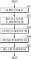
- FIG. 3is a flowchart of a method for providing virtual contents in a virtual space based on a common coordinate system between a field worker and a remote worker shown in FIG. 1.
- FIG. 4is a detailed flow diagram of a step of calculating an initial model matrix of the base marker and the target marker shown in FIG. 3.
- FIG. 5is a diagram illustrating a method of calculating an initial model matrix of a base marker and an initial model matrix of a target marker.
- FIG. 6is a diagram illustrating an example screen displayed on a display unit of a field device before and after a virtual work object is moved.
- FIG. 7is a detailed flow diagram of a step of calculating a current model matrix of the target marker shown in FIG. 3.
- FIG. 8is a diagram for explaining a method of calculating a current model matrix of a target marker.
- FIG. 9is a view showing an example screen displayed on the display unit of the field device and the remote device before and after the actual work object is moved.
- FIG. 10is a diagram illustrating an example screen displayed on a display unit of a field device and a remote device in a virtual work space according to the present embodiment.
- Embodiments of the present invention to be described belowrelate to a method of providing virtual content in a virtual space based on a common coordinate system. More specifically, it relates to a method of providing virtual contents between a field worker and a remote worker using a virtual space based on a common coordinate system.
- MRMated Reality
- devices of work participants located in remote locationsare connected to each other through a communication network, so that the work participants can monitor the work progress through Augmented Reality (AR) content or Virtual Reality (VR) content described below.
- ARAugmented Reality
- VRVirtual Reality
- a virtual object corresponding to an actual work targetwill be referred to as a “virtual work target”
- a virtual space corresponding to an actual work spacewill be referred to as a “virtual work space”.
- At least one participant who is located in the actual work space and performs work on the actual work targetis to be referred to as a “field worker”, and at least one participant who is located in a remote location of the real work space and participates in work on the actual work target Will be referred to as “remote worker”.
- a coordinate system of a virtual spacethat can be shared by a field worker's device and a remote worker's device and expressed in augmented reality or virtual reality is referred to as a “common coordinate system”.
- the virtual spacemay be provided to the user in virtual reality or augmented reality depending on the device.
- a virtual work system 1is a configuration diagram of a virtual work system 1 according to an embodiment of the present invention.
- a virtual work system 1includes a device 11 of a field worker 10 and a device 21 of a remote worker 20.
- the device 1 of the field worker 10 and the device 21 of the remote worker 20may be the same device.
- site device 11the device 11 of the field worker 10
- remote worker 21the remote worker
- the device 11 of (20)will be referred to as "remote device 21”.
- the on-site device 11 and the remote device 21are connected through the network 30 to communicate with each other.
- the plurality of work participants 10 and 20may perform work while sharing work situations in a mixed reality environment through contents displayed on their respective devices 11 and 21.
- the field worker 10 located in the actual work spacecan manipulate the actual work target through joint work with the remote worker 20, for example, joint work such as repair work or parts replacement work, or in a virtual space. You can do things like games. More specifically, the on-site device 11 uses its camera module 112 to photograph an actual work space, that is, an actual work object located at the work site, and responds to the actual work object photographed in this way in a virtual work space. A virtual work target is created, and data on the virtual work target in the virtual work space is transmitted to the remote device 21 of the remote worker 20 located at a remote location.
- the remote worker 20may manipulate the virtual work target using various input means while observing the virtual work target in the virtual work space displayed on the screen of the remote device 21.
- the manipulation of the virtual work target by the remote worker 20is reflected in the virtual work space, so that information on the manipulation of the virtual work target is transmitted to all field workers 10 and remote workers 20 using the virtual work application. do.
- the field worker 10can immediately know the work performed by the remote worker 20 in the virtual work space based on the change of the virtual work target in the virtual work space.
- the field worker 10can manipulate the actual work target of the work site by referring to work in the virtual work space.
- the virtual work technologyshares a virtual work target representing the actual work target between the remote worker 20, an expert located far away from the work target, and the field worker 10 located at the work site, so that the field worker ( 10) It is possible to allow the remote worker 20 to see the work performed in the virtual work space and manipulate the actual work target.
- the remote worker 20can grasp the movement of the actual work target manipulated by the field worker 10 while observing the virtual work target in the virtual work space displayed on the screen of the remote device 21. . By reflecting the manipulation of the actual work target by the field worker 10 in the virtual work space, information on the operation of the actual work target is transmitted to all field workers 10 and remote workers 20 using the virtual work application. do.
- the remote worker 20can immediately know the work performed by the field worker 10 in the actual work space based on the change of the virtual work target in the virtual work space.
- the remote worker 20may manipulate the virtual work target of the virtual work space by referring to work in the actual work space.
- the virtual work technologyshares a virtual work target representing the actual work target between the remote worker 20, an expert located far away from the work target, and the field worker 10 located at the actual work site. It is possible to allow the field worker 10 to observe the work performed in the actual work space in the virtual work space and manipulate the virtual work object.
- the field device 11is a device for enabling virtual work with a plurality of work participants 10 and 20 located at different places.
- the field device 11executes a virtual work application that performs a pre-installed remote collaboration service, and provides a remote collaboration service to a user through the virtual work application.
- the virtual work applicationis an application that connects the on-site devices 11 of a plurality of work participants through a network, and enables virtual work to a plurality of work participants located in separate places.
- the virtual work applicationis previously installed on the field device 11 before the virtual work.
- the on-site device 11includes a tablet PC, and other HMD (Head Mounted Display), VR (virtual reality) devices, smart phones, tablet PCs, and laptops ( laptop).
- the field device 11may be connected to a wireless communication network such as WCDMA and LTE to be connected to another field device 11.
- the remote device 21may be the same device as the field device 11.
- the field device 11includes a processor 111, a camera module 112, a marker detection unit 113, a virtual space processor 114, a matrix calculation unit 115, a display unit 116, and input. It consists of a module 117, a communication module 118, and a storage 119.
- the processor 111processes general tasks of the field device 11.
- the camera module 112photographs an actual work space in which the actual work target is located, and generates image data representing the actual work target and the actual work space.
- the marker detection unit 113analyzes image data generated from the camera module 112 to indicate a point serving as a reference point of the virtual work space in the actual work space where the actual work object is located, and a virtual work. A target marker indicating an actual work object in space is detected.
- the virtual space processing unit 114creates a virtual workspace that is a three-dimensional virtual space that mirrors part or all of the actual workspace from image data representing the actual workspace.
- the virtual space processing unit 114creates a virtual work target having the same 3D model shape as the actual work target for the virtual work of the field worker 10 and the remote worker 20, and virtually performs the generated virtual work target. Place it in the workspace.
- the virtual space processing unit 114detects a change in an actual operation object or a virtual operation object, and reflects the detected change in the actual operation object or virtual operation object in the virtual work space.
- the matrix calculator 115calculates a matrix representing a position and an orientation of an arbitrary object from a reference point in the virtual work space.
- the matrix calculator 115calculates a model matrix, a view matrix, and a model view matrix.
- the matrixis a mathematical tool for classifying a position and a direction based on an arbitrary origin of a virtual object in a virtual space and calculating the position and direction of a virtual object independent of each other.
- the model matrixis a matrix that expresses the state (position and orientation) of a virtual object in a virtual space.
- the model matrix of the virtual work objectis a matrix that expresses the position and direction of the virtual work object based on the origin on the virtual work space.
- the marker detection unit 113, the virtual space processing unit 114, and the matrix calculation unit 115may be implemented as a separate dedicated processor different from the processor 111, or by executing a computer program by the processor 111 It could be.
- the display unit 116displays a virtual work space including a virtual manipulation target corresponding to an actual manipulation target.
- the input module 117receives an input signal for manipulating a virtual work object on a virtual work space from a user. Examples of the input module 117 include a keyboard, a mouse, a touch screen panel, and a motion controller.
- the communication module 118supports a communication function so that it can communicate with other remote devices 21 through a wide area network such as the Internet by accessing an LTE base station or a Wi-Fi intermediary.
- the storage 119stores applications for virtual work and data used by these applications.
- the field device 11further includes additional components in addition to the components described above.
- the field device 11includes a bus for transmitting data between various components, as shown in FIG. 2, and is omitted in FIG. 2, but a power module that supplies driving power to each component. Includes.
- a bus for transmitting data between various componentsas shown in FIG. 2, and is omitted in FIG. 2, but a power module that supplies driving power to each component.
- FIG. 3is a flowchart of a method for providing virtual contents in a virtual space based on a common coordinate system between a field worker and a remote worker shown in FIG. 1.
- the method of providing virtual content according to the present embodimentincludes steps performed in a time series in the field device 11 shown in FIG. 1.
- the processor 111 of the field device 11executes the virtual job application. More specifically, when the processor 111 receives an execution command of the virtual job application from the field worker 10 through the input module 117, the processor 111 executes the virtual job application. Referring to FIG. 1, the field device 11 of the field worker 10 executes the virtual work application when an execution command of the virtual work application is input from the field worker 10. When the remote device 21 of the remote worker 20 also receives an execution command of the virtual job application from the remote worker 20, it executes the virtual job application. The field device 11 of the field worker 10 running the virtual work application and the remote device 21 of the remote worker 20 are connected to each other through a network.
- the camera module 112 of the field device 11generates initial image data indicating the initial state of the actual work object in the actual work space.
- the image datais an electrical signal representing a characteristic of a two-dimensional or three-dimensional shape, and is data generated by an input device such as the camera module 112.
- the remote worker 20photographs an actual work object, which is the target of the virtual work, using the camera module 112 of the field device 11 for virtual work with at least one remote worker 20 that is far away.
- the camera module 112generates initial image data representing an initial state of an actual manipulation target in an actual work space.
- the initial image datarepresents the initial state of the actual operation object including the position and direction of the actual work object in the actual work space before performing the virtual work.
- the camera module 112inputs the generated initial image data to the marker detection unit 113 of the field device 11.
- the marker detection unit 113 of the field device 11detects the base marker and the target marker from the initial image data input from the camera module 112. More specifically, the marker detection unit 113 includes a base marker for identifying a fixed point in an actual work space and a target marker for identifying an actual work object from initial image data representing the initial state of the actual work object in the actual work space. Is detected.
- the marker detection unit 113detects a base marker serving as a reference point in a virtual work space coordinate system from initial image data indicating an initial state of an actual work object in an actual work space, and detects a target marker indicating an actual work object.
- the base markerserves as a reference point in the virtual work space, and is a marker for identifying a fixed point in the real work space. Since the base marker serves as a reference point, the marker detection unit 113 detects a fixed point or object as a base marker.
- the target markeris a marker for identifying an object that is an actual work target of a virtual work.
- the base marker and the target markermay be set in advance by the field partner 10. The detection of the base marker and the target marker will be described in detail below.
- the marker detection unit 113extracts a shape included in image data through image processing, and detects a base marker and a target marker using the extracted shape. More specifically, the marker detection unit 113 extracts shapes included in initial image data representing an initial state of an actual work object in an actual work space. For example, the marker detection unit 113 extracts a feature point (keypoint) from initial image data.
- a feature pointis a point in an image that can be easily identified while being separated from the surrounding background.
- a feature pointis a point that can be easily identified even if the shape, size, or position of an object changes in image data, and is a point that can be easily identified even if the viewpoint and illumination of the camera change. Examples of feature points include corners and edges.
- the marker detection unit 113analyzes the extracted feature points and extracts shapes included in the image data.
- the marker detection unit 113may extract shapes included in the image data using an artificial neural network technique. Since the method of extracting feature points and shapes from image data is known to those of ordinary skill in the art to which this embodiment belongs, a detailed description thereof will be omitted in order to prevent blurring of the features of the embodiment. I will do it.
- the marker detection unit 113extracts a base marker and a target marker from among shapes extracted from initial image data. More specifically, the marker detection unit 113 compares the extracted shapes with the base marker shape and the target marker shape previously stored in the storage 119. Based on the comparison result, the marker detection unit 113 determines a shape that matches the shape of the base marker among shapes extracted from the image data as the base marker, and determines a shape that matches the shape of the target marker as the target marker. The marker detection unit 113 extracts the same shape as the shape of the base marker previously stored in the storage 119 of the field device 11 as a base marker, and uses the same shape as the shape of the target marker previously stored in the storage 119 as a target marker. Extract with.
- the storage 119 of the field device 11previously stores the shape of the base marker and the shape of the target marker.
- the shape of the base markeris the shape of a point or object that can serve as a reference point in the virtual work space. Since the base marker serves as a reference point in the virtual work space, a point or object that can be designated as a base marker must be fixed without moving. For example, the floor or desk of the space where the actual work object is placed, the pattern of the surrounding wallpaper, the QR code (Quick Response Code) attached to an object fixed in the actual collaboration space, a bar code, a specific pattern, etc. Can be.
- the field worker 10may predetermine the base marker in the actual work space by attaching the QR code of this specific pattern to a fixed object in the actual work space.
- the storage 119 of the field device 11stores image data representing the shape of a base marker, which is a shape of a fixed point or object in an actual work space.
- the marker detection unit 113extracts the shape of the base marker stored in the storage 119 from image data input by the camera module 117 (ie, image data representing the state of an actual work object in an actual work space). Compared with and, a shape matching the shape of the previously stored base marker is determined as the base marker.
- the shape of the target markeris the shape of the actual work target to be worked with the field worker 10 and the remote worker 20 in the virtual work space.
- the field worker 10determines the actual work target to perform the virtual work with the remote worker 20 in the actual work space.
- the field worker 10generates image data representing the shape of the actual work object determined using the camera module 112 of the field device 11.
- the field device 11stores image data representing the shape of the target marker, which is the shape of the actual work object, in the storage 119 in advance.
- the marker detection unit 113compares the shape of the actual work object stored in the storage 119 with shapes extracted from image data representing the state of the actual work object in the actual work space, and matches the shape of the target marker stored in advance.
- the shapeis determined as a target marker (ie, a work object in a virtual workspace).
- a target markerie, a work object in a virtual workspace.
- the storage 119 of the on-site device 11stores the shape of the actual work target powder container in advance.
- the marker detection unit 113 of the field device 11compares the shape extracted from image data representing the actual work object in the actual work space with the shape of the powder container previously stored in the storage 119. As a result of the comparison, a shape matching the shape of the powder container previously stored in the storage 119 as the shape of the target marker is determined as the target marker.
- the marker detection unit 113extracts the determined shape as a target marker.
- the storage 119 of the field device 11may store an arbitrary code such as a QR code or a bar code in the shape of a target marker.
- the field cooperative 10may designate an actual work target by attaching a QR code or barcode stored in the shape of a target marker to an actual work target to perform the virtual work.
- the actual work target of the virtual collaborationis a powder container
- the field worker 10attaches the QR code stored in the storage 119 in the shape of a target marker to the actual work target powder container.
- the marker detection unit 113compares the shape of the QR code or barcode stored in the storage 119 with the shapes extracted from image data representing the actual work object in the actual work space, and matches the shape of the previously stored QR code or barcode.
- the shape to be formedcan be determined as a target marker (ie, a work object).
- the target marker or the base markerincludes an electrical signal that cannot be identified with the naked eye.
- the field device 11may recognize a target marker or a base marker through a signal transmitted by a small wireless communication device.
- a wireless communication device that transmits a beacon signal including information on the shape and location of a base markeris attached to a fixed point in an actual working space, and a wireless communication device attached to a fixed point in the actual working space.
- the communication devicetransmits a signal for the base marker to the field device 11.
- the field device 11may identify the shape and location of the base marker based on the received signal for the base marker.
- a wireless communication devicethat transmits a beacon signal including information on the shape and location of the actual work target is attached to the actual work target, and the wireless communication device attached to the actual work target is a target marker. Transmit a signal for The field device 11 may identify the shape and location of the target marker based on the received signal for the target marker. The field device 11 may identify the target marker and the base marker in various ways in addition to the above-described examples.
- the virtual space processing unit 114 of the on-site device 11creates a virtual work space for a virtual work with the remote worker 20 and a virtual work target corresponding to the actual work target.
- the virtual space processing unit 114creates a virtual work space including a virtual work target corresponding to an actual work target of the virtual work.
- the virtual work spaceis a three-dimensional virtual space that mirrors part or all of the actual work space from image data representing the state of an actual work object in the real work space.
- a virtual workspaceis a three-dimensional space and may have an origin and X, Y, and Z axes.
- the virtual space processing unit 114creates a virtual work object having a 3D model shape of an actual work object.
- the virtual space processing unit 114creates a virtual work object having a cylindrical shape.
- the virtual space processing unit 114arranges a virtual work target, which is a 3D model shape of an actual work target, in a 3D virtual work space at an arbitrary location.
- a virtual work targetwhich is a 3D model shape of an actual work target
- an arbitrary position in which the virtual work target, which is a 3D model shape of the actual work target, is placedmay be set in advance by the designer.
- embodiments according to the present inventiondetermine the state (position and direction) of the target marker in the virtual work space using a base marker attached to a fixed point in the real work space, You can create a virtual workspace composed of a coordinate system with a common criterion.
- the matrix calculator 115 of the field device 11calculates a model matrix of the base marker detected in step 303 and an initial model matrix of the target marker from the initial image data generated in step 302.
- the model matrixrepresents the position and direction of an arbitrary point or object placed on the virtual workspace.
- the model matrix of the base markerrepresents the position and direction of the base marker on the virtual workspace
- the initial model matrix of the target markeris the model matrix of the target marker calculated first after the target marker is detected.
- the initial model matrix of the target markerbecomes a criterion for determining the change of the target marker in the virtual workspace.
- the field device 11calculates a model matrix of the target marker using image data representing the changed state of the actual work object, and By comparing with the initial model matrix, it is possible to know the change in the position and/or direction of the target marker, that is, the actual work object in the virtual work space.
- the initial model matrix of the target markeris a criterion for determining whether a change such as movement of the actual work object occurs in the virtual work.
- model matrix of the base marker and the initial model matrix of the target markerare calculated based on the camera module 112 of the on-site device 11, even if there is no change in the actual work target, the virtual device 11 is changed in position. There is a problem in that the location or direction of the base marker and the target marker in the work space is changed, so that incorrect information on the actual work object may be transmitted to the remote worker 20.
- the field device 11 of the field worker 10creates a virtual work space including a virtual work target corresponding to the actual work target.
- the on-site device 11In order for the on-site device 11 to display a virtual work space including a virtual operation target, it is necessary to know the position and direction in which the virtual work target corresponding to the actual work target is arranged in the virtual work space.
- the virtual work objectis arranged in a predetermined position and direction in the virtual work space.
- the location and direction of the virtual work object on the virtual work spacecan be expressed through the model matrix.
- the model matrix of the virtual work objectexpresses the position and direction of the virtual work object on the virtual work space.
- the field device 11is a field device 11 that photographs an actual work target in the actual work space in order to arrange the virtual work target corresponding to the actual work target in the virtual work space in the same state as the actual work target. You need to know the direction in which the camera module 112 looks at the actual work object in the actual work space.
- the view matrix of the camera module 112represents the direction in which the camera module 112 looks at the virtual work object corresponding to the actual work object in the virtual work space.
- the ModelView matrixexpresses the state (position and direction) of the virtual manipulation target on the virtual work space based on the camera module 112 of the field device 11.
- the model view matrix of the virtual work objectis a matrix expressing the position and direction of the virtual work target based on the view of the camera module 117 used to capture image data.
- the model view matrix of the virtual work targetmay be expressed as a product of a model matrix representing the position and direction of the virtual work target in the virtual work space and a view matrix representing the direction in which the camera module 112 looks at the manipulation target.
- the model view matrix, the model matrix, and the view matrixcan be expressed by the following equation.
- the model view matrix of the virtual work targetexpresses the position and direction of the virtual work target on the virtual work space according to the viewing direction of the camera module 112.
- the model view matrix of the virtual work targetmay be calculated from the image data representing the actual work target in the actual work space by the matrix calculation unit 115 of the field device 11. Since the model view matrix of the virtual work object calculated as described above is based on the camera module 112, the position and the direction of the virtual work object relative to the position and photographing direction of the camera module 112 are expressed.
- the model view matrix of the virtual work objectcan be calculated in the above-described manner, but the model matrix of the virtual work target expressing the absolute position and direction of the virtual work target in the virtual work space, and the camera module 112
- the view matrix of the camera module 112 representing the direction in which the virtual work object is viewedis not known.
- the model view matrix of the virtual work objectis the relative position and direction of the virtual work object according to the position and direction of the camera module 112
- the movement between the camera module 112 and the actual work objectmay have occurred. At this time, it is not known whether this movement is due to the movement of the camera module 112 or the movement of the actual work object. Due to such negativity (indeterminacy), in the virtual work, the remote worker 20 cannot know accurate information about the actual work target.
- FIG. 4is a detailed flow chart of the steps of calculating the model matrix of the base marker and the initial model matrix of the target marker shown in FIG. 3, and FIG. 5 is a description of a method of calculating the model matrix of the base marker and the initial model matrix of the target marker.
- step 3051the virtual space processor 114 designates an origin in the virtual work space created in step 304.
- the virtual space processing unit 114designates an arbitrary point in the created virtual work space as an origin.
- the matrix calculation unit 115is based on the initial image data representing the initial state of the actual work object in the actual work space, the initial model view matrix of the base marker (MV b matrix) and the initial model view of the target marker. Calculate the MV o matrix.
- the model view matrixrepresents the location and direction of the object on the virtual work space based on the camera module 112.
- the matrix calculating unit 115uses an algorithm for analyzing image data, and an initial model view matrix (MV b matrix) of the base marker according to the direction in which the camera module 112 looks at each of the base marker and the target marker, and a target marker. Calculate the initial model view matrix (MV o matrix) of.
- the matrix calculator 115calculates an initial model matrix (M o matrix) of the target marker on the virtual workspace.
- the target markeris a marker for identifying an actual work object, and it is assumed that the target marker is disposed at an arbitrary position on the virtual work space reflecting the actual work space.
- a matrix calculating unit 115calculates the initial model matrix (matrix M o) of the target marker placed at an arbitrary position from the reference point determined in step 3051.
- the matrix calculating unit 115using the initial model, the matrix of the target marker calculated in the initial model view matrix (MV o matrix) and 3053 steps of the target marker calculated in the 3052 phase (M o matrix) camera module
- the initial view matrix of (112)is calculated.
- the model view matrixis a product of the view matrix and the model matrix.
- the initial model view matrix (MV o matrix) of the target markeris an initial model matrix (M o matrix) expressing the position and direction of the target marker in the virtual workspace and the camera module 112 is virtual It can be expressed as a product of an initial view matrix expressing the direction in which the work object is viewed. Since the model matrix is invertible, if both sides of [Equation 1] are multiplied by the inverse matrix of the model matrix, it is summarized as the following equation.
- the matrix calculator 115may calculate an initial view matrix of the camera module 112 by using Equation 2 above.
- the matrix calculation unit 115uses the initial view matrix of the camera module 112 calculated in step 3054 and the initial model view matrix of the base marker (MV b matrix) to determine the model matrix of the base marker. Calculate (M b matrix).
- the initial model view matrix (MV b matrix) of the base markeris a model matrix (M b matrix) expressing the position and direction of the base marker in the virtual work space, and the camera module 112 is looking at the virtual work object. It can be expressed as a product of the initial view matrix representing the viewing direction. Therefore, the model matrix (M b matrix) of the base marker can be expressed by the following equation.
- Equations 2 and 3can be summarized as follows.
- the matrix calculator 115calculates a model matrix M b matrix of the base marker through Equation 4 above.
- the base markeris a marker that serves as a reference point in the virtual work space, and corresponds to a fixed point or object in an actual work site, so the base marker does not move. Accordingly, the model matrix M b matrix of the base marker is fixed.
- the matrix calculation unit 115 of the field device 11can calculate the model matrix of the base marker and the initial model matrix of the target marker in a virtual work space having a common coordinate system based on the base marker using the equations described above. have.
- step 306the processor 111 of the on-site device 11 sends a command for changing at least one of the position and direction of the virtual work target in the virtual work space from the remote device 21 of the remote worker 20 to the communication module 118 ).
- the remote worker 20may manipulate the position and direction of the virtual work target on the virtual work space through the virtual work application running on the remote device 21.
- a command for changing at least one of the position and direction of the virtual work target in the virtual work spaceis received by the remote worker 20 through the communication module 118 of the field device 11, the process proceeds to step 307, otherwise If not, proceed to step 308.
- step 307when a command for changing at least one of the location and direction of the virtual work target is received from the remote device 21 of the remote worker 20, the virtual space processing unit 114 of the on-site device 11 is received. Changes in the location and direction of the virtual work target are reflected in the virtual work space according to the command. When a change occurs in the virtual work target by the remote worker 20, the virtual space processing unit 114 of the on-site device 11 reflects the change of the generated virtual work target on the virtual work space. More specifically, when the remote worker 20 inputs a command to move or rotate the position of the virtual work object in the virtual work space to the remote device 21, the remote device 21 communicates with the remote device 21 The command for the change of the virtual work target is transmitted to the field device 11 through the module.
- the on-site device 11 receiving such a commandmoves or rotates the position of the virtual work target in the virtual work space according to the received command, so that the operation of the virtual work target by the remote worker 20 is performed in the virtual work space.
- the remote worker 20inputs a command to move the virtual work target to the remote device 21, the field device 11 of the field worker 10 is the remote device 21 of the remote worker 20.
- the command to move the virtual work objectis received.
- the field device 11 of the field worker 10moves the virtual work target on the virtual work space according to the received command.
- FIG. 6is a diagram illustrating an example screen displayed on a display unit of a user device before and after a virtual work object is moved.
- (a) of FIG. 6is an example of a screen displayed on the display unit 116 of the field device 11 in which the powder container and the virtual work target of the powder container, which are actual work targets, are displayed.
- the field device 11is photographing a powder container, which is an actual work object, and an actual working space in which the powder container is located, and the field device 11 is The actual work space is displayed through the display unit 116.
- a powder container that is an actual work object and a cylindrical virtual work object having the same shape as the powder containerare arranged in the same position and direction.
- the actual powder container and the cylindrical virtual work objectare overlapped and displayed on the display unit 116.
- Moves up 6Bis an example showing a screen displayed on the display unit 116 of the field device 11 of the field worker 10 when the virtual work object of the powder container is moved upward by the remote worker 20 to be.
- the field device 11is photographing an actual work target and an actual work space, and the display unit 116 of the field device 11 corresponds to the powder container and the powder container that are actual work targets.
- a cylindrical virtual work objectis displayed.
- the remote worker 20As described above, in the example in which a command to move the cylindrical virtual work object corresponding to the powder container upward on the virtual work space is input by the remote worker 20, it is displayed by the display unit 116 of the field device 11 The virtual work object is moved upward.
- the field worker 10can see the cylindrical virtual work object separated above, separate the powder container, which is the actual work target, and move it upward.
- the field worker 10may lift and remove the powder container from the actual work space according to the operation of the remote worker 20 on the virtual work space. In the above-described manner, the field worker 10 and the remote worker 20 can perform joint work through the virtual work space.
- step 308when a command for changing at least one of the location and direction of the virtual work target is not received from the remote device 21 of the remote worker 20, the on-site device 11 is a camera module of the on-site device 11 112 generates current image data indicating the current state of the work target and the work site. Since the location and direction of the actual work target continuously changes while the virtual work of the field worker 10 and the remote worker 20 is in progress, the field worker 10 is a field device for virtual work with the remote worker 20 Using the camera module 112 of 11), the changed actual work object is continuously photographed. The camera module 112 generates current image data indicating the current state of the actual work object in the actual work space.
- step 309the marker detection unit 113 of the field device 11 detects the base marker and the target marker from the current image data input from the camera module 112. A detailed description of the method of detecting the base marker and the target marker will be replaced with the content described in step 303.
- step 310the matrix calculator 115 of the field device 11 calculates the current model matrix of the target marker detected in step 309.
- the matrix calculating unit 115calculates a current model matrix representing the current state (position and direction) of the target marker.
- the model matrix representing the state (position and direction) of the target marker corresponding to the work objectis changed.
- FIG. 7is a detailed flow chart of a step of calculating the current model matrix of the target marker shown in FIG. 3, and FIG. 8 is a diagram illustrating a method of calculating the current model matrix of the target marker.
- the model view matrixis expressed as a product of the model matrix and the view matrix.
- the matrix calculation unit 115uses the current model view matrix (MV b ⁇ matrix) of the base marker and the current model view matrix (MV) of the target marker from the current image data representing the current state of the actual work object in the actual work space. o ⁇ matrix) is calculated.
- MVcurrent model view matrix
- MVcurrent model view matrix
- the matrix calculator 115calculates the current view matrix of the camera module 112 using the model matrix M b matrix of the base marker calculated in step 3055.
- the current model view matrix of the base marker(MV b ⁇ matrix) is the model matrix (M b matrix) and a camera module (112) representing the position and orientation of the base the marker is at the operation target in the virtual workspace It can be expressed as a product of the current view matrix representing the viewing direction.
- the model matrix of the base markeris constant. Accordingly, the current view matrix of the camera module 112 may be expressed in the following manner.
- the matrix calculator 115calculates the current view matrix of the camera module 112 through Equation (5).
- the matrix calculating unit 115is the current view matrix (View ⁇ matrix), and the current model view of the target marker calculated in step 3101 matrix (MV o ⁇ matrix) of the camera module 112 is determined in a step 3102 Is used to calculate the current model matrix (M o ⁇ matrix) of the target marker.
- the current model view matrix (MV o ⁇ matrix) of the target markeris the current model matrix (M o ⁇ matrix) representing the current position and direction of the target marker in the virtual workspace and the camera module 112 is currently It can be expressed as a product of the current view matrix representing the direction in which the object is viewed. Therefore, the current model matrix of the target marker (M o ⁇ matrix) can be expressed as follows.
- Equations 5 and 6can be summarized as follows.
- the matrix calculator 115calculates a current model matrix (M o ⁇ matrix) representing the current position and direction of the target marker through Equation 7 above.
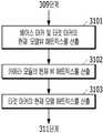
- step 311the virtual space processing unit 114 of the on-site device 11 updates the state of the virtual work object in the virtual work space according to the current model matrix of the target marker calculated in step 310 (M o ⁇ matrix).
- the target markerindicates the work object.
- the target marker's current model matrix (M o ⁇ matrix)represents the current position and direction of the work object in the virtual work space. It is not the same as compared to the current model matrix (M o ⁇ matrix) matrix initial model of the target marker (M matrix o) of the target marker can be seen to have occurred in the actual movement operation target.
- the change in the position or direction of the actual work objectappears in the current model matrix (M o ⁇ matrix) of the target marker calculated in step 310. Accordingly, in order to reflect the change of the actual work object in the virtual work space, the virtual space processing unit 114 applies the virtual work target in the virtual work space according to the current model matrix (M o ⁇ matrix) of the target marker in the virtual work space.
- the state of the virtual work object in the virtual work spacecan be updated by relocating it to the location and direction.
- the on-site device 11can reflect the change of the actual work object in the real work space in real time in the virtual work space.
- the virtual space processing unit 114 of the on-site device 11reflects the change in the state of the actual work target in the virtual work space by manipulating the virtual work target according to the current model matrix of the target marker when the state of the actual work target changes.
- FIG. 9is a diagram illustrating an example screen displayed on the display unit of the on-site device and the remote device before and after the actual work object is moved.
- (a) of FIG. 9shows that the virtual work target of the powder container and the powder container, which are actual work targets, is displayed on the display unit 116 of the field device 11 and the virtual work target of the virtual work space is remote.
- Thisis an example of a screen displayed on the display unit of the device 21.
- the field device 11is photographing a powder container, which is an actual work object, and an actual work space in which the powder container is located, and the field device 11 is a photographed powder container and an actual work space. The space is displayed through the display unit 116.
- a powder container that is an actual work object and a cylindrical virtual work object having the same shape as the powder containerare arranged in the same position and direction.
- the actual powder container and the cylindrical virtual work objectare overlapped and displayed on the display unit 116.
- the virtual work targetis disposed at an arbitrary position in the virtual work space.
- FIG. 9(b)shows the field device 11 of the field worker 10 and the remote device 21 of the remote worker 20 when the powder container, which is the actual work object, is moved from the actual work space by the field worker 10.
- the on-site device 11is photographing an actual work object
- the display units of the on-site device 11 and the remote device 21have a cylindrical shape corresponding to the powder container and the powder container that are actual work targets.
- the virtual work targetis displayed.
- the powder containerwhich is the actual work object
- the powder container which is the actual work object displayed by the display unit of the site device 11 and the remote device 21 And the cylindrical virtual work objectsall move in the same direction.
- the remote worker 20can check the manipulation of the actual work target by the field worker 10 through the change of the virtual work target. As described above, since the manipulation of the actual work target is directly reflected on the virtual work target on the virtual work space, the remote worker 20 can accurately know the current state of the real work target in the real work space. Accordingly, a precise collaboration between the field worker 10 and the remote worker 20 can be performed.
- step 312the display unit 116 of the field device 11 displays the current state of the virtual work target in the virtual work space reflected in step 307 or updated in step 310 to the field worker 10, and the communication module ( 118) transmits the current state of the virtual work target in the virtual work space reflected in step 307 or updated in step 310 to the remote device 21, thereby transferring the virtual content in the virtual space based on the common coordinate system to the field worker 10 remotely. It can be provided to the worker 20. As described above, the change in the location and direction of the virtual work target is reflected on the virtual work space according to the command input by the remote worker 20 through the remote device 21, or the actual work is performed by the field worker 10.
- the state of the virtual work target on the virtual work spaceis updated according to the change of the position and direction of the actual work target in the space, and the state of the virtual work target changes in the virtual work space.
- the display unit 116 of the on-site device 11displays the current state of the changed virtual work target in the virtual work space.
- the field worker 10refers to the current state of the virtual work target displayed on the display unit 116 of the field device 11 to perform work on the actual work target, for example, repair work or replacement work of parts. Can be done.
- the field device 11transmits data representing the current state of the virtual work target in the virtual work space to the remote device 21 through the communication module 118.
- the remote device 21displays the current state of the virtual work target in the virtual work space on the display of the remote device 21 according to the transmitted data.
- the remote worker 20may know the state of the actual work target in the actual work space through the current state of the virtual work target displayed on the display unit of the remote device 21.
- the remote worker 20refers to the state of the actual work target in the actual work space, and performs work on the virtual work target in the virtual work space, and provides work information on the actual work target to the field worker 10. I can.
- the embodiments of the present inventionmonitor the state of the virtual work target, which is virtual content in a virtual work space based on a common coordinate system, through the field device 11 and the remote device 12, to the field worker 10 and the remote worker.
- the state of the virtual work targetwhich is virtual content in a virtual work space based on a common coordinate system
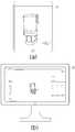
- FIG. 10is a diagram illustrating an example screen displayed on the display unit of the on-site device and the remote device in the virtual work space according to the present embodiment.
- (A) of FIG. 10is a diagram showing a screen displayed on the field device 11 of the field worker 10, and FIG. 10(b) shows the virtual work space is remote from the remote worker 20 A diagram showing a screen displayed on the device 21.
- the on-site device 11is a device supporting AR (augmented reality)
- ARaugmented reality
- the virtual work target corresponding to the actual work targetis matched with the real work target and is displayed overlaid at the same location.
- the remote device 21receives data on the virtual work space and the virtual work target from the field device 11 through the network 30, and uses the transmitted data to indicate the state of the virtual work target in the virtual work space. Screens can be presented to remote workers. Referring to FIG. 10B, when the remote device 21 is a device that supports virtual reality (VR), a screen representing a virtual work target and a virtual work space is provided to the remote worker 20.
- VRvirtual reality
- the screen on which the virtual work object is displayed in the virtual work spaceis variable according to the virtual environment supported by the device.
- the on-site devicewhen the on-site device is a device supporting AR, the on-site device displays an augmented reality screen, and when the remote device is a device supporting VR, the remote device displays a virtual reality screen.
- the field deviceis a device that supports VR
- the field devicedisplays a virtual reality screen
- the remote devicedisplays an augmented reality screen.
- Steps 306 to 312are repeatedly performed while the virtual work between the field worker 10 and the remote worker 20 is being performed.
- the remote worker 20manipulates the virtual work target through the remote device 21 during the virtual work between the field worker 10 and the remote worker 20, manipulation of the virtual work target in the virtual work space
- the field device 11uses a camera module to photograph the actual work target in the real work space in real time, and the work performed by the field worker 10 on the actual work target in the real work space is performed in the virtual work space.
- the method of providing virtual content in a virtual space based on a common coordinate systemdesignates a fixed point of an actual work space as a base marker, and indicates an actual work object based on the fixed base marker. Calculate a model matrix of the target marker that represents the state (position and direction) of the target marker.
- the coordinate system and scale of the virtual work spaceare fixed. Accordingly, the coordinate system and scale of all work participants sharing the virtual work space are unified. By fixing the coordinate system and scale on the virtual work space, accurate information on the actual work object can be delivered to remote workers participating in the virtual work.
- the method of providing virtual content in a virtual space based on a common coordinate systemis to identify changes in the state (position and direction) of the actual work object and the movement of the camera module based on a fixed base marker,
- the devicecan distinguish between the movement of the object and the movement of the camera module.
- the user devicecalculates a model matrix of a target marker and a view matrix of a camera module based on the base marker, thereby discriminating and reflecting the movement of the work object and the camera module in the virtual work space. Accordingly, the user device according to embodiments of the present invention can prevent a problem in which the camera movement is incorrectly reflected on the virtual work space due to the movement of the work object.
- the user device according to the exemplary embodiments of the present inventioncan transmit accurate information on the work target to remote workers participating in the virtual work by distinguishing the movement of the work target and the movement of the camera module.
- the above-described embodiments of the present inventioncan be written as a program that can be executed in a computer, and can be implemented in a general-purpose digital computer that operates the program using a computer-readable recording medium.
- the structure of the data used in the above-described embodiment of the present inventioncan be recorded on a computer-readable recording medium through various means.
- the computer-readable recording mediumincludes a storage medium such as a magnetic storage medium (for example, ROM, floppy disk, hard disk, etc.) and an optical reading medium (for example, CD-ROM, DVD, etc.).
Landscapes
- Engineering & Computer Science (AREA)
- Theoretical Computer Science (AREA)
- Physics & Mathematics (AREA)
- General Physics & Mathematics (AREA)
- Software Systems (AREA)
- Computer Vision & Pattern Recognition (AREA)
- General Engineering & Computer Science (AREA)
- Computer Graphics (AREA)
- Multimedia (AREA)
- Computer Hardware Design (AREA)
- Radar, Positioning & Navigation (AREA)
- Databases & Information Systems (AREA)
- Evolutionary Computation (AREA)
- General Health & Medical Sciences (AREA)
- Medical Informatics (AREA)
- Health & Medical Sciences (AREA)
- Artificial Intelligence (AREA)
- Computing Systems (AREA)
- Remote Sensing (AREA)
- Architecture (AREA)
- Processing Or Creating Images (AREA)
- Human Computer Interaction (AREA)
- Geometry (AREA)
- User Interface Of Digital Computer (AREA)
Abstract
Description
Translated fromKorean가상공간에서 가상 컨텐츠 제공 방법에 관한 것으로, 보다 구체적으로 베이스 마커를 기준으로 공통 좌표계 기반의 가상공간에서 가상 컨텐츠 제공 방법에 관한 것이다.The present invention relates to a method of providing virtual content in a virtual space, and more particularly, to a method of providing virtual content in a virtual space based on a common coordinate system based on a base marker.
가상공간이란 실제 공간의 일부 또는 전체를 반영하는(mirroring) 3차원의 가상의 공간을 의미한다. 가상공간은 컴퓨터 등에 의해 생성된 실제가 아닌 가상의 대상 및 공간을 포함한다. 이러한 가상공간은 증강현실(AR, Augmented Reality) 기술, 가상현실(VR, Virtual Reality) 기술, 또는 혼합현실(Mixed Reality) 기술을 통해 사용자에게 해당 공간을 제공한다. 이러한 가상공간은 최근 게임, 항공, 군사 등의 다양한 분야에서 활용되고 있다. 가상공간을 활용하는 대표적인 예로는 원격협업이 있다.The virtual space refers to a three-dimensional virtual space that mirrors part or all of the actual space. Virtual space includes virtual objects and spaces that are not real and created by a computer or the like. Such a virtual space provides a corresponding space to users through Augmented Reality (AR) technology, Virtual Reality (VR) technology, or Mixed Reality technology. These virtual spaces are recently used in various fields such as games, aviation, and military. A representative example of using virtual space is remote collaboration.
원격협업이란 상호간에 물리적으로 떨어진 원격지에 위치하는 여러 작업자들이 의사소통을 하며 동일한 과업을 함께 해결하는 것을 의미한다. 즉, 원격협업이란 여러 작업 참여자가 동일한 공간에 모이지 않고 서로 다른 공간에서 정보를 공유하면서 동시에 작업을 수행함을 의미한다. 이러한 원격협업은 모든 작업참여자가 동일한 공간에 모여야 하는 공간적인 제약을 해소할 수 있다.Remote collaboration means that multiple workers located in remote locations physically separated from each other communicate and solve the same task together. In other words, remote collaboration means that multiple work participants do not gather in the same space, but share information in different spaces while simultaneously performing work. Such remote collaboration can remove the spatial constraints that all working participants must gather in the same space.
이러한 원격협업에서 작업 참여자들은 네트워크를 통하여 서로 연결되어 동일한 화면을 공유한다. 원격협업의 예시로는 비디오 컨퍼런스나 동일한 화면을 공유하여 원격지에 위치한 작업 참여자들이 동일한 과업을 함께 해결할 수 있게 하는 것들이 있다. 과거의 원격협업은 작업 참여자들이 음성, 채팅 등을 통해 의사소통하며 협업하는 방식이었다. 최근의 원격협업은 보다 많은 정보를 제공하기 위하여 증강현실(AR, Augmented Reality), 가상현실(VR, Virtual Reality), 또는 혼합현실(Mixed Reality)을 이용하여 원격협업의 작업 참여자들 사이에서 공유되는 협업공간을 제공한다. 증강현실, 가상현실, 또는 혼합현실이 적용된 협업공간은 실제 협업대상이 실재하는 공간의 일부 또는 전체를 반영하는 가상의 공간이다. 이러한 가상의 협업공간을 작업 참여자들에게 제공하고, 가상의 협업공간에서 작업 참여자들은 공동작업을 수행할 수 있다.In such remote collaboration, work participants are connected to each other through a network and share the same screen. Examples of remote collaboration include video conferences or sharing the same screen so that working participants in remote locations can work on the same task together. In the past, remote collaboration was a method in which working participants communicated and collaborated through voice and chat. In order to provide more information, the recent remote collaboration uses augmented reality (AR), virtual reality (VR), or mixed reality to provide more information. Provide a space for collaboration. A collaboration space to which augmented reality, virtual reality, or mixed reality is applied is a virtual space that reflects part or all of the space where the actual collaboration target exists. This virtual collaborative space is provided to the working participants, and the working participants can collaborate in the virtual collaborative space.
이러한 원격협업 서비스에서 복수의 작업 참여자들 중 어느 하나의 작업 참여자가 가상 협업공간에서 임의의 작업을 수행하면, 어느 하나의 작업 참여자에 의해 수행된 작업이 가상 협업공간 상에 반영되어 모든 작업 참여자들에게 전달된다. 여기에서, 복수의 작업 참여자들 간에 가상 협업공간에서의 좌표계 및 스케일이 통일되지 않는 경우 어느 하나의 작업 참여자에 의해 수행된 작업이 가상 협업공간에 정확하게 반영되지 않는 문제점이 있다. 작업 참여자들 중 임의의 작업 참여자에 의해 가상 협업공간에서 가상 협업대상이 이동된 예시에서, 작업 참여자들 사이의 좌표 스케일이 상이하면 어느 하나의 작업 참여자에 의해 협업대상이 이동되더라도 협업대상의 정확한 이동거리를 다른 작업 참여자들이 알 수 없다. 또한, 상술한 예시에서 가상 협업공간의 좌표계가 일치하지 않으면 어느 하나의 작업 참여자에 의해 협업대상이 이동되더라도 협업대상의 이동방향을 다른 작업 참여자들이 알 수 없다.In this remote collaboration service, when any one of the multiple work participants performs a random work in the virtual collaboration space, the work performed by any one work participant is reflected on the virtual collaboration space and all work participants Delivered to. Here, if the coordinate system and scale in the virtual collaboration space are not unified among the plurality of work participants, there is a problem that the work performed by any one work participant is not accurately reflected in the virtual collaboration space. In the example in which the virtual collaboration target is moved from the virtual collaboration space by a random work participant among the work participants, if the coordinate scale between the work participants is different, even if the collaboration target is moved by any one work participant, the collaboration target is accurately moved. The distance is unknown to other participants. In addition, in the above-described example, if the coordinate system of the virtual collaboration space does not match, even if the collaboration object is moved by any one work participant, other work participants cannot know the moving direction of the collaboration object.
상술한 바와 같이, 원격협업 시스템의 가상 협업공간 상에서 좌표계 및 스케일이 통일되지 않음에 따라 작업 참여자의 작업에 대한 정확한 정보를 다른 작업 참여자들에 제공할 수 없다. 이에 따라, 가상 협업공간 상에서 복수의 작업 참여자들 간의 원활한 협업을 방해하는 문제점이 있다.As described above, since the coordinate system and scale are not unified in the virtual collaboration space of the remote collaboration system, accurate information about the work of the work participant cannot be provided to other work participants. Accordingly, there is a problem in preventing smooth collaboration between a plurality of work participants in a virtual collaboration space.
종래의 원격협업 시스템은 이러한 문제점을 해결하기 위하여 좌표계 및 스케일이 작업 참여자들 사이에서 일치하지 않는 경우, 작업참여자들 각각이 자신의 디바이스에서의 가상 협업공간의 좌표계와 스케일을 조절하여 작업 참여자들 간에 좌표계 및 스케일을 일치시키는 방식을 사용한다. 그러나, 이러한 종래의 방식은 여러 작업 참여자들 각자가 자신의 디바이스에서 가상 협업공간의 좌표계 및 스케일을 수동으로 조절하기 때문에 모든 작업 참여자들의 좌표계 및 스케일이 완벽하게 일치될 수 없는 문제점이 존재한다.In order to solve this problem, the conventional remote collaboration system adjusts the coordinate system and scale of the virtual collaborative space on their device when the coordinate system and scale do not match among the working participants. Use a method of matching the coordinate system and scale. However, this conventional method has a problem in that the coordinate system and scale of all the work participants cannot be perfectly matched because each of the various work participants manually adjusts the coordinate system and scale of the virtual collaboration space on their device.
공통 좌표계 기반의 가상공간에서 가상 콘텐츠 제공 방법을 제시하는 데에 있다. 또한, 상기된 바와 같은 기술적 과제들로 한정되지 않으며, 이하의 설명으로부터 또 다른 기술적 과제가 도출될 수도 있다.It is to propose a method of providing virtual contents in a virtual space based on a common coordinate system. Further, it is not limited to the technical problems as described above, and another technical problem may be derived from the following description.
본 발명의 일 측면에 따른 공통 좌표계 기반의 가상공간에서 가상 컨텐츠 제공 방법은 실제 작업공간에서의 실제 작업대상의 초기 상태를 나타내는 초기 이미지 데이터로부터 상기 실제 작업공간의 고정 지점을 식별하기 위한 마커인 베이스 마커 및 상기 실제 작업대상을 식별하기 위한 마커인 타겟 마커를 검출하는 단계; 상기 검출된 베이스 마커를 기준으로 하는 공통 좌표계를 갖는 가상 작업공간에서 상기 타겟 마커의 초기 위치 및 방향을 표현하는 타겟 마커의 초기 모델 매트릭스, 및 상기 검출된 베이스 마커의 위치 및 방향을 표현하는 상기 베이스 마커의 모델 매트릭스를 산출하는 단계; 및 상기 산출된 베이스 마커의 모델 매트릭스를 이용하여 상기 타겟 마커의 현재 위치 및 방향을 표현하는 상기 타겟 마커의 현재 모델 매트릭스를 산출하는 단계를 포함한다.A method of providing virtual contents in a virtual space based on a common coordinate system according to an aspect of the present invention is a base, which is a marker for identifying a fixed point of the actual working space from initial image data indicating an initial state of an actual work object in the real working space. Detecting a marker and a target marker that is a marker for identifying the actual work object; An initial model matrix of a target marker expressing the initial position and direction of the target marker in a virtual work space having a common coordinate system based on the detected base marker, and the base expressing the position and direction of the detected base marker Calculating a model matrix of markers; And calculating a current model matrix of the target marker expressing the current position and direction of the target marker using the calculated model matrix of the base marker.
상기 타겟 마커를 검출하는 단계는 상기 초기 이미지 데이터에 포함된 형상을 추출하고, 상기 추출된 형상을 이용하여 상기 베이스 마커 및 상기 타겟 마커를 검출한다.In the detecting of the target marker, a shape included in the initial image data is extracted, and the base marker and the target marker are detected using the extracted shape.
상기 타겟 마커를 검출하는 단계는 상기 추출된 형상을 상기 베이스 마커의 형상 및 상기 타겟 마커의 형상과 비교하고, 상기 베이스 마커의 형상과 매칭되는 형상을 상기 베이스 마커로 검출하고, 상기 타겟 마커의 형상과 매칭되는 형상을 상기 타겟 마커로 검출한다.In the detecting of the target marker, the extracted shape is compared with the shape of the base marker and the shape of the target marker, a shape matching the shape of the base marker is detected as the base marker, and the shape of the target marker A shape matching with is detected with the target marker.
상기 베이스 마커의 모델 매트릭스를 산출하는 단계는 상기 초기 이미지 데이터에 기초하여 상기 초기 이미지 데이터의 촬영에 사용된 카메라 모듈의 뷰를 기준으로 상기 베이스 마커의 위치 및 방향을 나타내는 상기 베이스 마커의 초기 모델뷰 매트릭스 및 상기 카메라 모듈의 뷰를 기준으로 상기 타겟 마커의 위치 및 방향을 나타내는 상기 타겟 마커의 초기 모델뷰 매트릭스를 산출하는 단계; 상기 가상 협업공간 상에서 상기 타겟 마커의 초기 모델 매트릭스를 산출하는 단계; 및 상기 산출된 베이스 마커의 초기 모델뷰 매트릭스, 상기 산출된 타겟 마커의 초기 모델 매트릭스, 상기 산출된 타겟 마커의 초기 모델뷰 매트릭스를 이용하여 상기 베이스 마커의 모델 매트릭스를 산출하는 단계를 포함한다.The calculating of the model matrix of the base marker may include an initial model view of the base marker indicating the position and direction of the base marker based on the view of the camera module used to capture the initial image data based on the initial image data. Calculating an initial model view matrix of the target marker indicating the position and direction of the target marker based on a matrix and a view of the camera module; Calculating an initial model matrix of the target marker on the virtual collaboration space; And calculating a model matrix of the base marker using the calculated initial model view matrix of the base marker, the calculated initial model matrix of the target marker, and the calculated initial model view matrix of the target marker.
상기 산출된 베이스 마커의 초기 모델뷰 매트릭스, 상기 산출된 타겟 마커의 초기 모델 매트릭스, 상기 산출된 타겟 마커의 초기 모델뷰 매트릭스를 이용하여 상기 베이스 마커의 모델 매트릭스를 산출하는 단계는 아래의 수학식에 따라 상기 베이스 마커의 모델 매트릭스를 산출한다.The step of calculating the model matrix of the base marker using the calculated initial model view matrix of the base marker, the calculated initial model matrix of the target marker, and the calculated initial model view matrix of the target marker is expressed by the following equation. Accordingly, a model matrix of the base marker is calculated.
<수학식><Equation>
Mb matrix = Mo matrix * (MVo matrix)-1 * MVb matrixMb matrix = Mo matrix * (MVo matrix)-1 * MVb matrix
(Mb matrix : 베이스 마커의 모델 매트릭스, MVb matrix : 베이스 마커의 초기 모델뷰 매트릭스, Mo matrix : 타겟 마커의 초기 모델 매트릭스, MVo matrix : 타겟 마커의 초기 모델뷰 매트릭스)(Mb matrix: model matrix of base marker, MVb matrix: initial model view matrix of base marker, Mo matrix: initial model matrix of target marker, MVo matrix: initial model view matrix of target marker)
상기 타겟 마커의 현재 모델 매트릭스를 산출하는 단계는 상기 현재 이미지 데이터에 기초하여 상기 베이스 마커의 현재 모델뷰 매트릭스 및 상기 타겟 마커의 현재 모델뷰 매트릭스를 산출하는 단계; 및 상기 산출된 베이스 마커의 현재 모델뷰 매트릭스, 상기 산출된 타겟 마커의 현재 모델뷰 매트릭스, 및 상기 산출된 베이스 마커의 모델 매트릭스를 이용하여 상기 타겟 마커의 현재 모델 매트릭스를 산출하는 단계를 포함한다.The calculating of the current model matrix of the target marker may include calculating a current model view matrix of the base marker and a current model view matrix of the target marker based on the current image data; And calculating a current model matrix of the target marker using the calculated current model view matrix of the base marker, the calculated current model view matrix of the target marker, and the calculated model matrix of the base marker.
상기 산출된 베이스 마커의 현재 모델뷰 매트릭스, 상기 산출된 타겟 마커의 현재 모델뷰 매트릭스, 및 상기 산출된 베이스 마커의 모델 매트릭스를 이용하여 상기 타겟 마커의 현재 모델 매트릭스를 산출하는 단계는 아래의 수학식에 따라 상기 타겟 마커의 현재 모델 매트릭스를 산출한다.The step of calculating the current model matrix of the target marker using the calculated current model view matrix of the base marker, the calculated current model view matrix of the target marker, and the calculated model matrix of the base marker includes the following equation: According to the current model matrix of the target marker is calculated.
<수학식><Equation>
Mo` matrix = Mb matrix * (MVb` matrix)-1 * MVo` matrixM o `matrix = M b matrix * (MV b` matrix) -1 * MV o `matrix
(Mo` matrix : 타겟 마커의 현재 모델 매트릭스, MVo` matrix : 타겟 마커의 현재 모델뷰 매트릭스, MVb` matrix : 베이스 마커의 현재 모델뷰 매트릭스, Mb matrix : 베이스 마커의 모델 매트릭스)(Mo `matrix: Current model matrix of target marker, MVo` matrix: Current model view matrix of target marker, MVb `matrix: Current model view matrix of base marker, Mb matrix: Model matrix of base marker)
본 발명의 일 측면에 따른 공통 좌표계 기반의 가상공간에서 가상 컨텐츠 제공 방법은 상기 원격작업자의 원격 디바이스로부터 상기 가상 작업대상의 위치 및 방향을 변화시키는 명령이 수신되었는지 여부를 결정하는 단계; 및 상기 가상 작업대상의 위치 및 방향을 변화시키는 명령이 수신된 경우, 상기 수신된 명령에 따라 상기 가상 작업공간 상에서 상기 가상 작업대상의 위치 및 방향의 변화를 반영하는 단계를 더 포함한다.According to an aspect of the present invention, a method of providing virtual content in a virtual space based on a common coordinate system includes determining whether a command for changing the location and direction of the virtual work object is received from the remote device of the remote worker; And when a command for changing the position and direction of the virtual work object is received, reflecting a change in the position and direction of the virtual work target on the virtual work space according to the received command.
본 발명의 일 측면에 따른 공통 좌표계 기반의 가상공간에서 가상 컨텐츠 제공 방법은 상기 산출된 타겟 마커의 현재 모델 매트릭스에 따라 상기 가상 작업공간 상에서 상기 가상 작업대상의 위치 및 방향을 업데이트하는 단계를 더 포함한다.A method of providing virtual content in a virtual space based on a common coordinate system according to an aspect of the present invention further includes updating the position and direction of the virtual work object on the virtual work space according to the calculated current model matrix of the target marker. do.
본 발명의 다른 측면에 따른 디바이스는 실제 작업공간에서의 실제 작업대상의 초기 상태를 나타내는 초기 이미지 데이터로부터 상기 실제 작업공간의 고정 지점을 식별하기 위한 마커인 베이스 마커 및 상기 실제 작업대상을 식별하기 위한 마커인 타겟 마커를 검출하는 마커 검출부; 상기 검출된 베이스 마커를 기준으로 하는 공통 좌표계를 갖는 가상 협업공간에서 상기 타겟 마커의 초기 위치 및 방향을 표현하는 타겟 마커의 초기 모델 매트릭스, 및 상기 검출된 베이스 마커의 위치 및 방향을 표현하는 상기 베이스 마커의 모델 매트릭스를 산출하고, 상기 산출된 베이스 마커의 모델 매트릭스를 이용하여 상기 타겟 마커의 현재 위치 및 방향을 표현하는 상기 타겟 마커의 현재 모델 매트릭스를 산출하는 매트릭스 산출부를 포함한다.A device according to another aspect of the present invention includes a base marker that is a marker for identifying a fixed point of the actual work space from initial image data representing an initial state of an actual work object in an actual work space, and a base marker for identifying the actual work object. A marker detection unit that detects a target marker that is a marker; An initial model matrix of a target marker representing the initial position and direction of the target marker in a virtual collaborative space having a common coordinate system based on the detected base marker, and the base representing the position and direction of the detected base marker And a matrix calculator configured to calculate a model matrix of a marker, and calculate a current model matrix of the target marker representing the current position and direction of the target marker using the calculated model matrix of the base marker.
현장작업자의 현장디바이스는 실제 작업공간의 고정된 지점을 베이스 마커로 지정하고, 고정된 베이스 마커를 기준으로 가상 작업공간 상에서 실제 작업대상에 대응되는 가상 작업대상의 위치 및 방향을 결정한다. 즉, 본 발명에 따른 가상 콘텐츠 제공 방법은 실제 작업공간의 고정된 지점에 부착된 베이스 마커를 기준으로 실제 작업대상의 변화를 검출하고, 이를 가상 작업공간에 반영한다(mirroring). 고정된 베이스 마커를 기준으로 실제 작업대상의 위치 및 방향의 변화를 산출하고 이를 가상 작업공간 상의 가상 작업대상에 반영함으로써, 사용자 디바이스는 좌표계 및 스케일이 일정한 가상 작업공간을 생성할 수 있다. 다시 말해, 원격작업자들에게 공통된 좌표계를 갖는 가상 작업공간을 생성할 수 있다. 이에 따라, 서로 다른 공간에 위치한 원격작업자들에게 실제 작업대상의 위치 및 방향의 변화에 대한 정확한 정보가 제공될 수 있다.The field device of the field worker designates a fixed point of the actual work space as a base marker, and determines the position and direction of the virtual work object corresponding to the actual work object on the virtual work space based on the fixed base marker. That is, the method of providing virtual content according to the present invention detects a change in an actual work object based on a base marker attached to a fixed point of the actual work space, and reflects the change in the virtual work space (mirroring). By calculating the change in the position and direction of the actual work target based on the fixed base marker and reflecting the change in the virtual work target on the virtual work space, the user device can create a virtual work space having a constant coordinate system and scale. In other words, it is possible to create a virtual workspace with a common coordinate system for remote workers. Accordingly, accurate information on changes in the location and direction of the actual work target can be provided to remote workers located in different spaces.
본 발명의 실시예들에 따른 가상 콘텐츠 제공 방법은 고정된 베이스 마커를 기준으로 실제 작업대상의 움직임 및 카메라 모듈의 움직임을 파악함으로써, 사용자 디바이스가 실제 작업대상의 움직임과 카메라 모듈의 움직임을 구별할 수 있다. 사용자 디바이스는 베이스 마커를 기준으로 타겟 마커의 모델 매트릭스 및 카메라 모듈의 뷰 매트릭스를 산출함으로써, 가상 작업공간에 실제 작업대상의 움직임 및 카메라 모듈의 움직임을 구별하여 반영할 수 있다. 이에 따라, 본 발명의 실시예들에 따른 사용자 디바이스는 카메라 움직임이 실제 작업대상의 움직임으로 가상 협업공간 상에 잘 못 반영되는 문제를 방지할 수 있다.In the method of providing virtual content according to embodiments of the present invention, by grasping the movement of the actual work object and the movement of the camera module based on a fixed base marker, the user device can distinguish between the movement of the actual work object and the movement of the camera module. I can. The user device may differentiate and reflect the movement of the actual work object and the camera module in the virtual work space by calculating the model matrix of the target marker and the view matrix of the camera module based on the base marker. Accordingly, the user device according to embodiments of the present invention can prevent a problem in which the camera movement is incorrectly reflected on the virtual collaboration space as the movement of the actual work object.
상술한 바와 같이, 본 발명의 실시예들에 따른 가상 컨텐츠 제공 방법은 공통 좌표계 및 스케일을 갖는 가상 작업공간을 생성하고 생성된 가상 작업공간을 복수의 작업참여자들에게 제공함으로써, 작업참여자들 간의 원활하고 정확한 가상작업을 가능하게 한다. 이에 더하여, 공통 좌표계 기반의 가상 작업공간은 좌표계가 일정하기 때문에 가상현실, 증강현실 또는 혼합현실 등 다양한 확장현실로 표시될 수 있다.As described above, the virtual content providing method according to the embodiments of the present invention creates a virtual workspace having a common coordinate system and scale, and provides the created virtual workspace to a plurality of work participants, thereby smoothly between the work participants. And enables accurate virtual work. In addition, since the common coordinate system-based virtual working space has a constant coordinate system, it can be displayed in various extended reality such as virtual reality, augmented reality, or mixed reality.
도 1은 본 발명의 일 실시예에 따른 가상작업시스템의 구성도이다.1 is a configuration diagram of a virtual work system according to an embodiment of the present invention.
도 2는 도 1에 도시된 현장 디바이스의 구성도이다.2 is a configuration diagram of the field device shown in FIG. 1.
도 3은 도 1에 도시된 현장작업자와 원격작업자 간의 공통 좌표계 기반의 가상공간에서 가상 컨텐츠 제공 방법의 흐름도이다.3 is a flowchart of a method for providing virtual contents in a virtual space based on a common coordinate system between a field worker and a remote worker shown in FIG. 1.
도 4는 도 3에 도시된 베이스 마커 및 타겟 마커의 초기 모델 매트릭스를 산출하는 단계의 상세흐름도이다.4 is a detailed flow diagram of a step of calculating an initial model matrix of the base marker and the target marker shown in FIG. 3.
도 5는 베이스 마커의 초기 모델 매트릭스 및 타겟 마커의 초기 모델 매트릭스를 계산하는 방법을 설명하는 도면이다.5 is a diagram illustrating a method of calculating an initial model matrix of a base marker and an initial model matrix of a target marker.
도 6은 가상 작업대상이 이동 전후의 현장 디바이스의 디스플레이부에 표시되는 예시화면을 도시한 도면이다.6 is a diagram illustrating an example screen displayed on a display unit of a field device before and after a virtual work object is moved.
도 7은 도 3에 도시된 타겟 마커의 현재 모델 매트릭스를 산출하는 단계의 상세흐름도이다.7 is a detailed flow diagram of a step of calculating a current model matrix of the target marker shown in FIG. 3.
도 8은 타겟 마커의 현재 모델 매트릭스를 계산하는 방법을 설명하는 도면이다.8 is a diagram for explaining a method of calculating a current model matrix of a target marker.
도 9는 실제 작업대상이 이동 전후의 현장 디바이스 및 원격 디바이스의 디스플레이부에 표시되는 예시화면을 도시한 도면이다.9 is a view showing an example screen displayed on the display unit of the field device and the remote device before and after the actual work object is moved.
도 10은 본 실시예에 따른 가상 작업공간이 현장 디바이스 및 원격 디바이스의 디스플레이부에 표시되는 예시화면을 도시한 도면이다.10 is a diagram illustrating an example screen displayed on a display unit of a field device and a remote device in a virtual work space according to the present embodiment.
이하에서는 도면을 참조하여 본 발명의 실시예들을 상세하게 설명한다. 이하에서 설명될 본 발명의 실시예들은 공통 좌표계 기반의 가상공간에서 가상 컨텐츠 제공 방법에 관한 것이다. 보다 구체적으로, 공통 좌표계 기반의 가상공간을 이용하여 현장작업자와 원격작업자 사이에서 가상 컨텐츠 제공 방법에서 관한 것이다. 본 발명의 실시예들이 속하는 기술분야에서 통상의 지식을 가진 자라면, 이하에서 설명될 "혼합현실(MR, Mixed Reality)"은 현실과 가상을 결합하여 현실의 물리적 객체와 가상 객체들이 공존하는 새로운 환경을 만들고 사용자가 해당 환경과 실시간으로 상호작용할 수 있는 기술을 의미하는 것임을 이해할 수 있다.Hereinafter, exemplary embodiments of the present invention will be described in detail with reference to the drawings. Embodiments of the present invention to be described below relate to a method of providing virtual content in a virtual space based on a common coordinate system. More specifically, it relates to a method of providing virtual contents between a field worker and a remote worker using a virtual space based on a common coordinate system. For those of ordinary skill in the art to which the embodiments of the present invention belong, "Mixed Reality (MR)", which will be described below, is a new method in which real physical objects and virtual objects coexist by combining reality and virtuality. It can be understood that it refers to the technology that creates an environment and allows users to interact with that environment in real time.
이하의 실시예에 따르면, 상호간에 원격지에 위치한 작업 참여자들의 디바이스들이 통신 네트워크를 통해 서로 연결되어 작업 참여자들은 이하에서 설명되는 AR(Augmented Reality) 컨텐츠 또는 VR(Virtual Reality) 컨텐츠를 통해 작업 진행 상황을 공유하게 된다. 이하에서는 실제 작업대상에 대응되는 가상의 객체를 “가상 작업대상”으로, 실제 작업공간에 대응되는 가상의 공간을 "가상 작업공간"이라고 호칭하기로 한다. 실제 작업공간에 위치하여 실제 작업대상에 대한 작업을 수행하는 적어도 한명의 참여자를 “현장작업자”로 호칭하기로 하고, 실제 작업공간의 원격지에 위치하여 실제 작업대상에 대한 작업에 참여하는 적어도 한 명의 참여자를 “원격작업자”로 호칭하기로 한다. 또한, 현장작업자의 디바이스와 원격작업자의 디바이스가 공유하고 증강현실 또는 가상현실로 표현될 수 있는 가상공간의 좌표계를 “공통 좌표계”로 호칭하기로 한다. 여기에서, 가상공간은 디바이스에 따라 가상현실 또는 증강현실로 사용자에게 제공될 수 있다.According to the following embodiment, devices of work participants located in remote locations are connected to each other through a communication network, so that the work participants can monitor the work progress through Augmented Reality (AR) content or Virtual Reality (VR) content described below. Will share. Hereinafter, a virtual object corresponding to an actual work target will be referred to as a “virtual work target”, and a virtual space corresponding to an actual work space will be referred to as a “virtual work space”. At least one participant who is located in the actual work space and performs work on the actual work target is to be referred to as a “field worker”, and at least one participant who is located in a remote location of the real work space and participates in work on the actual work target Will be referred to as “remote worker”. In addition, a coordinate system of a virtual space that can be shared by a field worker's device and a remote worker's device and expressed in augmented reality or virtual reality is referred to as a “common coordinate system”. Here, the virtual space may be provided to the user in virtual reality or augmented reality depending on the device.
도 1은 본 발명의 일 실시예에 따른 가상작업시스템(1)의 구성도이다. 도 1을 참고하면, 본 실시예에 따른 가상작업시스템(1)은 현장작업자(10)의 디바이스(11)와 원격작업자(20)의 디바이스(21)로 구성된다. 현장작업자(10)의 디바이스(1)와 원격작업자(20)의 디바이스(21)는 동일한 디바이스일 수 있다. 이하에서는 현장작업자(10)의 디바이스(11)와 원격작업자(20)의 디바이스(11)를 구별하기 위하여, 현장작업자(10)의 디바이스(11)를 “현장디바이스(11)”로, 원격작업자(20)의 디바이스(11)를 “원격디바이스(21)”로 호칭하기로 한다. 현장디바이스(11)와 원격디바이스(21)는 네트워크(30)를 통해 연결되어 서로 통신을 하게 된다. 복수의 작업참여자(10, 20)는 각자의 디바이스(11, 21)에 표시되는 컨텐츠를 통해 혼합현실 환경에서 작업 상황을 공유하면서 작업을 수행할 수 있다.1 is a configuration diagram of a virtual work system 1 according to an embodiment of the present invention. Referring to FIG. 1, a virtual work system 1 according to the present embodiment includes a
실제 작업공간에 위치해 있는 현장작업자(10)는 원격작업자(20)와의 공동 작업을 통하여 실제 작업대상에 대한 조작, 예를 들어 고장 부위의 수리 작업이나 부품 교체 작업과 같은 공동작업 또는 가상공간 상에서의 게임과 같은 작업을 수행할 수 있다. 보다 구체적으로, 현장디바이스(11)는 그것의 카메라 모듈(112)을 이용하여 실제 작업공간, 즉 작업현장에 위치된 실제 작업대상을 촬영하고, 가상 작업공간에서 이와 같이 촬영된 실제 작업대상에 대응되는 가상 작업대상을 생성하고, 가상 작업공간에서의 가상 작업대상에 대한 데이터를 원격지에 위치하는 원격작업자(20)의 원격디바이스(21)로 전송한다.The
원격작업자(20)는 원격디바이스(21)의 화면에 표시된 가상 작업공간에서의 가상 작업대상을 관찰하면서 각종 입력수단을 이용하여 가상 작업대상을 조작할 수 있다. 원격작업자(20)에 의한 가상 작업대상에 대한 조작이 가상 작업공간에 반영됨으로써, 가상작업 어플리케이션을 사용하는 모든 현장작업자(10) 및 원격작업자(20)에게 가상 작업대상의 조작에 대한 정보가 전달된다. 현장작업자(10)는 가상 작업공간에서의 가상 작업대상의 변화에 기초하여 원격작업자(20)가 가상 작업공간에서 수행한 작업을 바로 알 수 있다. 현장작업자(10)는 가상 작업공간에서의 작업을 참조하여 작업현장의 실제 작업대상을 조작할 수 있다. 상술한 바와 같이, 가상작업 기술은 작업대상과 멀리 떨어진 곳에 있는 전문가인 원격작업자(20)와 작업현장에 위치한 현장작업자(10) 사이에 실제 작업대상을 나타내는 가상 작업대상을 공유함으로써, 현장작업자(10)로 하여금 원격작업자(20)가 가상 작업공간에서 수행한 작업을 보고 실제 작업대상을 조작하도록 할 수 있다.The
현장 작업자(10)와 마찬가지로 원격작업자(20)는 원격디바이스(21)의 화면에 표시된 가상 작업공간에서의 가상 작업대상을 관찰하면서 현장작업자(10)가 조작한 실제 작업대상의 움직임을 파악할 수 있다. 현장작업자(10)에 의한 실제 작업대상에 대한 조작이 가상 작업공간에 반영됨으로써, 가상작업 어플리케이션을 사용하는 모든 현장작업자(10) 및 원격작업자(20)에게 실제 작업대상의 조작에 대한 정보가 전달된다. 원격작업자(20)는 가상 작업공간에서의 가상 작업대상의 변화에 기초하여 현장작업자(10)가 실제 작업공간에서 수행한 작업을 바로 알 수 있다. 원격작업자(20)는 실제 작업공간에서의 작업을 참조하여 가상 작업공간의 가상 작업대상을 조작할 수 있다. 상술한 바와 같이, 가상작업 기술은 작업대상과 멀리 떨어진 곳에 있는 전문가인 원격작업자(20)와 실제 작업현장에 위치한 현장작업자(10) 사이에 실제 작업대상을 나타내는 가상 작업대상을 공유함으로써, 원격작업자(20)로 하여금 현장작업자(10)가 실제 작업공간에서 수행한 작업을 가상 작업공간에서 관찰하고 가상 작업대상을 조작하도록 할 수 있다.Like the
현장디바이스(11)는 서로 떨어진 장소에 위치하는 복수의 작업참여자(10, 20)와의 가상작업을 가능하게 하기 위한 장치이다. 현장디바이스(11)는 미리 설치된 원격협업 서비스를 수행하는 가상작업 어플리케이션을 실행하고, 가상작업 어플리케이션을 통해 사용자에게 원격협업 서비스를 제공한다. 가상작업 어플리케이션은 네트워크를 통하여 복수의 작업참여자의 현장디바이스(11)을 연결하여, 서로 떨어진 장소에 있는 복수의 작업참여자에게 가상작업을 가능하게 하는 어플리케이션이다. 이하에서는 가상작업 전에 현장디바이스(11)에 가상작업 어플리케이션이 미리 설치되어 있는 것으로 가정한다. 현장디바이스(11)의 대표적인 예로는 태블릿(tablet) PC를 들 수 있고, 그 외 HMD(Head Mounted Display), VR(virtual reality) 기기, 스마트폰(smart phone), 태블릿(tablet) pc, 랩탑(laptop) 등을 들 수 있다. 또한, 현장디바이스(11)는 WCDMA, LTE와 같은 무선 통신망에 접속되어 다른 현장디바이스(11)과 연결될 수 있다. 앞서 설명한 바와 같이, 원격디바이스(21)는 현장디바이스(11)와 동일한 디바이스일 수 있다.The
도 2는 도 1에 도시된 현장디바이스(11)의 구성도이다. 도 2를 참고하면, 현장디바이스(11)는 프로세서(111), 카메라 모듈(112), 마커 검출부(113), 가상공간 프로세서(114), 매트릭스 산출부(115), 디스플레이부(116), 입력모듈(117), 통신모듈(118), 및 스토리지(119)로 구성된다. 프로세서(111)는 현장디바이스(11)의 일반적인 태스크를 처리한다. 카메라 모듈(112)은 실제 작업대상이 위치하는 실제 작업공간을 촬영하여, 실제 작업대상 및 실제 작업공간을 나타내는 이미지 데이터를 생성한다. 마커 검출부(113)는 카메라 모듈(112)로부터 생성된 이미지 데이터를 분석하여 실제 작업대상이 위치하는 실제 작업공간에서 가상 작업공간의 기준점 역할을 하는 지점을 지시하는 베이스 마커(base marker) 및 가상 작업공간에서의 실제 작업대상을 지시하는 타겟 마커(target marker)를 검출한다. 가상공간 처리부(114)는 실제 작업공간을 나타내는 이미지 데이터로부터 실제 작업공간의 일부 또는 전체를 반영하는(mirroring) 3차원의 가상의 공간인 가상 작업공간을 생성한다. 또한, 가상공간 처리부(114)는 현장작업자(10)와 원격작업자(20)의 가상작업을 위하여 실제 작업대상과 동일한 3차원 모델 형상을 갖는 가상 작업대상을 생성하고, 생성된 가상 작업대상을 가상 작업공간에 배치한다. 가상공간 처리부(114)는 실제 조작대상 또는 가상 조작대상의 변화를 검출하고, 검출된 실제 작업대상 또는 가상 조작대상의 변화를 가상 작업공간에 반영한다.2 is a configuration diagram of the
매트릭스 산출부(115)는 가상 작업공간에서 기준점으로부터 임의의 대상의 상태인 위치(position)와 방향(oientation)을 표현하는 매트릭스(matrix)를 산출한다. 매트릭스 산출부(115)는 모델(model) 매트릭스, 뷰(view) 매트릭스, 및 모델뷰(ModelView) 매트릭스를 산출한다. 여기에서, 매트릭스는 가상 공간에서 가상 물체의 임의의 원점을 기준으로 위치와 방향으로 구분하고, 서로 독립적인 가상 물체의 위치 및 방향을 계산하기 위한 수학적 도구이다. 모델 매트릭스는 가상 공간에서 가상 물체의 상태(위치 및 방향)를 표현하는 매트릭스이다. 예를 들어, 가상 작업대상의 모델 매트릭스는 가상 작업공간 상에서 원점을 기준으로 가상 작업대상의 위치 및 방향을 표현하는 매트릭스이다. 모델 매트릭스, 뷰 매트릭스 및 모델뷰 매트릭스에 대하여는 이하에서 상세하게 설명하기로 한다. 여기에서, 마커 검출부(113), 가상공간 처리부(114) 및 매트릭스 산출부(115)는 프로세서(111)와는 다른 별개의 전용 프로세서로 구현될 수도 있고, 프로세서(111)의 컴퓨터 프로그램 실행에 의해 구현될 수도 있다.The
디스플레이부(116)는 실제 조작대상에 대응되는 가상 조작대상을 포함하는 가상 작업공간을 표시한다. 입력모듈(117)은 사용자로부터 가상 작업공간 상에서 가상 작업대상을 조작하는 입력 신호를 수신한다. 입력모듈(117)의 예로는 키보드, 마우스, 터치스크린 패널, 모션 컨트롤러 등을 들 수 있다. 통신모듈(118)은 LTE 기지국 또는 와이파이 중개기에 접속하여 인터넷 등과 같은 광역 네트워크를 통하여 다른 원격디바이스(21)와 통신할 수 있도록 통신기능을 지원한다. 스토리지(119)에는 가상작업을 위한 어플리케이션 및 이러한 어플리케이션에 의해 사용되는 데이터가 저장된다.The
현장디바이스(11)는 이상에서 설명된 구성요소들 외에 추가적인 구성요소를 더 포함한다. 예를 들어, 현장디바이스(11)는 도 2에 도시된 바와 같이, 여러 구성요소들 간에 데이터를 전송하기 위한 버스를 포함하고, 도 2에는 생략되어 있으나 각 구성요소에 구동전원을 공급하는 전력모듈을 포함한다. 이와 같이, 본 실시예가 속하는 기술분야에서 통상의 지식을 가진 자에게 자명한 구성요소에 대한 설명은 본 실시예의 특징을 흐려지게 함에 따라 생략된다. 이하에서는 본 발명의 일 실시예에 따른 공통 좌표계 기반의 가상공간에서 가상 컨텐츠 제공 방법을 설명하는 과정에서 현장디바이스(11)의 각 구성요소에 대해 상세하게 설명하기로 한다.The
도 3은 도 1에 도시된 현장작업자와 원격작업자 간의 공통 좌표계 기반의 가상공간에서 가상 컨텐츠 제공 방법의 흐름도이다. 도 3을 참고하면, 본 실시예에 따른 가상 컨텐츠 제공 방법은 도 1에 도시된 현장디바이스(11)에서 시계열적으로 수행되는 단계들로 구성된다.3 is a flowchart of a method for providing virtual contents in a virtual space based on a common coordinate system between a field worker and a remote worker shown in FIG. 1. Referring to FIG. 3, the method of providing virtual content according to the present embodiment includes steps performed in a time series in the
301 단계에서, 현장디바이스(11)의 프로세서(111)는 가상작업 어플리케이션을 실행한다. 보다 구체적으로, 프로세서(111)는 입력모듈(117)을 통해 현장작업자(10)로부터 가상작업 어플리케이션의 실행 명령을 입력받으면, 가상작업 어플리케이션을 실행한다. 도 1을 참고하면, 현장작업자(10)의 현장디바이스(11)는 현장작업자(10)로부터 가상작업 어플리케이션의 실행 명령을 입력받은 경우 가상작업 어플리케이션을 실행한다. 원격작업자(20)의 원격 디바이스(21) 또한 원격작업자(20)로부터 가상작업 어플리케이션의 실행 명령을 입력받은 경우 가상작업 어플리케이션을 실행한다. 가상작업 어플리케이션을 실행한 현장작업자(10)의 현장디바이스(11)과 원격작업자(20)의 원격디바이스(21)는 네트워크를 통하여 서로 연결된다.In
302 단계에서, 현장디바이스(11)의 카메라 모듈(112)은 실제 작업공간에서의 실제 작업대상의 초기 상태를 나타내는 초기 이미지 데이터를 생성한다. 여기에서, 이미지 데이터는 2차원 또는 3차원 형상의 특징을 나타내는 전기적 신호로서, 카메라 모듈(112)과 같은 입력 장치에 의해 생성되는 데이터이다. 원격작업자(20)는 멀리 떨어져 있는 적어도 한명의 원격작업자(20)와의 가상작업을 위하여 가상작업의 대상이 되는 실제 작업대상을 현장디바이스(11)의 카메라 모듈(112)을 이용하여 촬영한다. 카메라 모듈(112)은 실제 작업공간에서의 실제 조작대상의 초기 상태를 나타내는 초기 이미지 데이터를 생성한다. 초기 이미지 데이터는 가상작업을 수행하기 전에 실제 작업공간에서 실제 작업대상의 위치 및 방향을 포함하는 실제 조작대상의 초기 상태를 나타낸다. 초기 이미지 데이터는 가상작업 수행 전에 실제 작업대상의 상태를 나타내기 때문에, 가상작업 수행 중에 실제 작업대상의 상태가 변화하였는지를 판정하는 기준이 된다. 카메라 모듈(112)은 생성된 초기 이미지 데이터를 현장디바이스(11)의 마커 검출부(113)로 입력한다.In
303 단계에서, 현장디바이스(11)의 마커 검출부(113)는 카메라 모듈(112)로부터 입력된 초기 이미지 데이터로부터 베이스 마커 및 타겟 마커를 검출한다. 보다 구체적으로, 마커 검출부(113)는 실제 작업공간에서의 실제 작업대상의 초기 상태를 나타내는 초기 이미지 데이터로부터 실제 작업공간에서 고정된 지점을 식별하기 위한 베이스 마커 및 실제 작업대상을 식별하기 위한 타겟 마커를 검출한다. 마커 검출부(113)는 실제 작업공간에서의 실제 작업대상의 초기 상태를 나타내는 초기 이미지 데이터로부터 가상 작업공간 좌표계에서의 기준점이 되는 베이스 마커를 검출하고, 실제 작업대상을 나타내는 타겟 마커를 검출한다. 위에서 설명한 바와 같이, 베이스 마커는 가상 작업공간에서 기준점 역할을 하는 마커로서, 실제 작업공간에서 고정된 지점을 식별하기 위한 마커이다. 베이스 마커는 기준점 역할을 하기 때문에, 마커 검출부(113)는 고정된 지점 또는 물체를 베이스 마커로서 검출한다. 타겟 마커는 가상작업의 실제 작업대상인 물체를 식별하기 위한 마커이다. 베이스 마커 및 타겟 마커는 현장협업자(10)에 의하여 미리 설정될 수 있다. 베이스 마커 및 타겟 마커의 검출에 대하여는 이하에서 상세하게 설명하기로 한다.In
본 발명의 일 실시예에 따른 마커 검출부(113)는 이미지 프로세싱을 통하여 이미지 데이터에 포함된 형상을 추출하고, 추출된 형상을 이용하여 베이스 마커 및 타겟 마커를 검출한다. 보다 구체적으로, 마커 검출부(113)는 실제 작업공간에서의 실제 작업대상의 초기 상태를 나타내는 초기 이미지 데이터에 포함된 형상들을 추출한다. 예를 들어, 마커 검출부(113)는 초기 이미지 데이터에서 특징점(feature point, keypoint)을 추출한다. 특징점은 이미지에서 주위 배경과 구분되면서 식별이 용이한 지점이다. 특징점은 이미지 데이터에서 물체의 형태, 크기 또는 위치가 변하더라도 용이하게 식별이 가능한 지점이고, 카메라의 시점 및 조명이 변하더라도 용이하게 식별 가능한 지점이다. 특징점의 예로는 모서리(corner), 경계선(edge) 등을 들 수 있다. 마커 검출부(113)는 추출된 특징점을 분석하여 이미지 데이터에 포함된 형상들을 추출한다. 마커 검출부(113)는 인공신경망(Artificial Neural Network) 기법을 이용하여 이미지 데이터에 포함된 형상들을 추출할 수 있다. 이미지 데이터로부터 특징점 및 형상을 추출하는 방법은 본 실시예가 속하는 기술분야에서 통상의 지식을 가진 자에게 공지되어 있으므로, 이에 대한 상세한 설명은 본 실시예의 특징이 흐려짐을 방지하기 위하여 더 이상의 자세한 설명은 생략하기로 한다.The
마커 검출부(113)는 초기 이미지 데이터로부터 추출된 형상들 중 베이스 마커와 타겟 마커를 추출한다. 보다 구체적으로, 마커 검출부(113)는 추출된 형상들을 스토리지(119)에 미리 저장된 베이스 마커 형상 및 타겟 마커 형상과 비교한다. 마커 검출부(113)는 비교결과에 기초하여 이미지 데이터로부터 추출된 형상들 중 베이스 마커의 형상과 일치하는 형상을 베이스 마커로 결정하고, 타겟 마커의 형상과 일치하는 형상을 타겟 마커로 결정한다. 마커 검출부(113)는 현장디바이스(11)의 스토리지(119)에 미리 저장된 베이스 마커의 형상과 동일한 형상을 베이스 마커로 추출하고, 스토리지(119)에 미리 저장된 타겟 마커의 형상과 동일한 형상을 타겟 마커로 추출한다.The
현장디바이스(11)의 스토리지(119)는 베이스 마커의 형상 및 타겟 마커의 형상을 미리 저장하고 있다. 상술한 바와 같이, 베이스 마커의 형상은 가상 작업공간에서 기준점 역할을 할 수 있는 지점 또는 물체의 형상이다. 베이스 마커는 가상 작업공간에서 기준점 역할을 하기 때문에 베이스 마커로 지정될 수 있는 지점 또는 물체는 움직이지 않고 고정되어 있어야 한다. 예를 들어, 실제 작업대상이 놓이는 공간의 바닥이나 책상, 주변 벽지의 패턴, 실제 협업공간에 고정된 물체에 부착된 QR 코드(Quick Response Code), 바코드(bar code), 특정 패턴 등이 베이스 마커가 될 수 있다. 베이스 마커의 형상으로 특정 패턴의 QR 코드가 저장된 경우, 현장작업자(10)는 이러한 특정 패턴의 QR 코드를 실제 작업공간의 고정된 물체에 부착하는 방식으로 실제 작업공간에서 베이스 마커를 미리 결정할 수 있다. 현장디바이스(11)의 스토리지(119)는 실제 작업공간에서 고정된 지점 또는 물체의 형상인 베이스 마커의 형상을 나타내는 이미지 데이터를 저장한다. 마커 검출부(113)는 스토리지(119)에 저장된 베이스 마커의 형상을 카메라 모듈(117)에 의해 입력된 이미지 데이터(즉, 실제 작업공간에서 실제 작업대상의 상태를 나타내는 이미지 데이터)로부터 추출된 형상들과 비교하고, 미리 저장된 베이스 마커의 형상과 일치하는 형상을 베이스 마커로 결정한다.The
또한, 상술한 바와 같이, 타겟 마커의 형상은 가상 작업공간에서 현장작업자(10)와 원격작업자(20)가 함께 작업할 실제 작업대상의 형상이다. 현장작업자(10)는 실제 작업공간에서 원격작업자(20)와 가상작업을 수행할 실제 작업대상을 결정한다. 본 발명의 일 실시예에서, 현장작업자(10)는 현장디바이스(11)의 카메라 모듈(112)을 이용하여 결정된 실제 작업대상의 형상을 나타내는 이미지 데이터를 생성한다. 현장디바이스(11)는 실제 작업대상의 형상인 타겟 마커의 형상을 나타내는 이미지 데이터를 스토리지(119)에 미리 저장한다. 마커 검출부(113)는 스토리지(119)에 저장된 실제 작업대상의 형상을 실제 작업공간에서의 실제 작업대상의 상태를 나타내는 이미지 데이터로부터 추출된 형상들과 비교하고, 미리 저장된 타겟 마커의 형상과 일치하는 형상을 타겟 마커(즉, 가상 작업공간에서의 작업대상)로 결정한다. 가상작업의 실제 작업대상이 3D 프린터의 분말통인 경우를 예로 들면, 현장디바이스(11)의 스토리지(119)는 실제 작업대상인 분말통의 형상을 미리 저장하고 있다. 현장디바이스(11)의 마커 검출부(113)는 실제 작업공간에서의 실제 작업대상을 나타내는 이미지 데이터로부터 추출된 형상을 스토리지(119)에 미리 저장된 분말통의 형상과 비교한다. 비교 결과, 스토리지(119)에 미리 타겟 마커의 형상으로 저장된 분말통의 형상과 일치하는 형상을 타겟 마커로 결정한다. 마커 검출부(113)는 결정된 형상을 타겟 마커로 추출한다.In addition, as described above, the shape of the target marker is the shape of the actual work target to be worked with the
본 발명의 다른 실시예에서, 현장디바이스(11)의 스토리지(119)는 타겟 마커의 형상으로 QR 코드, 바코드(bar code) 등과 같은 임의의 코드를 저장할 수 있다. 현장협업자(10)는 가상작업을 수행할 실제 작업대상에 타겟 마커의 형상으로 저장된 QR 코드 또는 바코드을 부착하여, 실제 작업대상을 지정할 수 있다. 가상협업의 실제 작업대상이 분말통인 경우를 예로 들면, 현장작업자(10)는 스토리지(119)에 타겟 마커 형상으로 저장된 QR 코드를 실제 작업대상인 분말통에 부착한다. 마커 검출부(113)는 스토리지(119)에 저장된 QR 코드 또는 바코드의 형상과 실제 작업공간에서의 실제 작업대상을 나타내는 이미지 데이터로부터 추출된 형상들과 비교하고, 미리 저장된 QR 코드 또는 바코드의 형상과 일치하는 형상을 타겟 마커(즉, 작업 대상)로 결정할 수 있다.In another embodiment of the present invention, the
본 발명의 또 다른 실시예에서, 타겟 마커 또는 베이스 마커는 육안으로 식별이 불가능한 전기적 신호를 포함한다. 예를 들어, 현장 디바이스(11)는 소형 무선통신 디바이스에 의해 송신되는 신호를 통하여 타겟 마커 또는 베이스 마커를 인식할 수 있다. 예를 들어, 베이스 마커의 형상 및 위치에 대한 정보를 포함하는 비컨(beacon) 신호를 송신하는 무선통신 디바이스가 실제 작업공간의 고정된 지점에 부착되고, 실제 작업공간의 고정된 지점에 부착된 무선통신 디바이스는 현장 디바이스(11)로 베이스 마커에 대한 신호를 송신한다. 현장 디바이스(11)는 수신된 베이스 마커에 대한 신호에 기초하여 베이스 마커의 형상 및 위치를 식별할 수 있다. 타겟 마커 또한 실제 작업대상의 형상 및 위치에 대한 정보를 포함하는 비컨 신호를 송신하는 무선통신 디바이스가 실제 작업대상에 부착되고, 실제 작업대상에 부착된 무선통신 디바이스는 현장 디바이스(11)로 타겟 마커에 대한 신호를 송신한다. 현장 디바이스(11)는 수신된 타겟 마커에 대한 신호에 기초하여 타겟 마커의 형상 및 위치를 식별할 수 있다. 현장 디바이스(11)는 상술한 예시 이외에도 다양한 방법으로 타겟 마커 및 베이스 마커를 식별할 수 있다.In another embodiment of the present invention, the target marker or the base marker includes an electrical signal that cannot be identified with the naked eye. For example, the
304 단계에서, 현장디바이스(11)의 가상공간 처리부(114)는 원격작업자(20)와의 가상작업을 위한 가상 작업공간, 및 실제 작업대상에 대응되는 가상 작업대상을 생성한다. 가상공간 처리부(114)는 가상작업의 실제 작업대상에 대응되는 가상 작업대상을 포함하는 가상 작업공간을 생성한다. 가상 작업공간은 실제 작업공간에서의 실제 작업대상의 상태를 나타내는 이미지 데이터로부터 실제 작업공간의 일부 또는 전체를 반영하는(mirroring) 3차원의 가상의 공간이다. 예를 들어, 가상 작업공간은 3차원 공간으로서, 원점과 X, Y, Z축을 가질 수 있다. 가상공간 처리부(114)는 실제 작업대상의 3차원 모델 형상을 갖는 가상 작업대상을 생성한다. 예를 들어, 실제 작업대상이 원통형의 분말통인 경우, 가상공간 처리부(114)는 원통형의 형상을 갖는 가상 작업대상을 생성한다. 그리고, 가상공간 처리부(114)는 3차원의 가상 작업공간에 실제 작업대상의 3차원 모델 형상인 가상 작업대상을 임의의 위치에 배치한다. 여기서 실제 작업대상의 3차원 모델 형상인 가상 작업대상이 배치되는 임의의 위치는 설계자에 의해 미리 설정될 수 있다. 이하에서 설명할 바와 같이, 본 발명에 따른 실시예들은 실제 작업공간에서 고정된 지점에 부착된 베이스 마커를 이용하여 가상 작업공간에서 타겟 마커의 상태(위치 및 방향)을 결정함으로써, 실제 작업공간과 공통된 기준을 갖는 좌표계로 구성되는 가상 작업공간을 생성할 수 있다.In
305 단계에서, 현장디바이스(11)의 매트릭스 산출부(115)는 302 단계에서 생성된 초기 이미지 데이터로부터 303 단계에서 감지된 베이스 마커의 모델 매트릭스 및 타겟 마커의 초기 모델 매트릭스를 산출한다. 모델 매트릭스는 가상 작업공간 상에 배치된 임의의 지점 또는 물체의 위치 및 방향을 표현한다. 예를 들어, 베이스 마커의 모델 매트릭스는 가상 작업공간 상에서 베이스 마커의 위치 및 방향을 표현하고, 타겟 마커의 초기 모델 매트릭스는 타겟 마커가 감지된 후 가장 먼저 산출된 타겟 마커의 모델 매트릭스로서, 가상 작업공간에서 가상작업의 가상 작업대상의 초기 상태(위치 또는 방향)를 표현한다. 따라서, 타겟 마커의 초기 모델 매트릭스는 가상 작업공간에서 타겟 마커의 변화를 결정하는 기준이 된다. 실제 작업대상의 상태(위치 및 방향)가 변화된 경우, 타겟 마커의 상태가 변하기 때문에 타겟 마커의 초기 모델 매트릭스와 타겟 마커의 현재 상태를 표현하는 현재 모델 매트릭스가 차이가 발생한다.In
보다 상세하게 설명하면, 실제 작업대상의 위치 또는 방향에 변화가 발생된 경우, 현장디바이스(11)는 변화된 실제 작업대상의 상태를 나타내는 이미지 데이터를 이용하여 타겟 마커의 모델 매트릭스를 산출하고 타겟 마커의 초기 모델 매트릭스와 비교함으로써, 가상 작업공간에서 타겟 마커, 즉 실제 작업대상의 위치 및/또는 방향의 변화를 알 수 있다. 타겟 마커의 초기 모델 매트릭스는 가상작업에서 실제 작업대상의 움직임 등과 같은 변화가 발생하였는지를 결정하는 기준이다.In more detail, when a change occurs in the position or direction of the actual work object, the
현장디바이스(11)의 카메라 모듈(112)을 기준으로 베이스 마커의 모델 매트릭스 및 타겟 마커의 초기 모델 매트릭스를 산출하게 되면, 실제 작업대상의 변화가 없더라도 현장디바이스(11)의 위치가 변경됨에 따라 가상 작업공간에서 베이스 마커 및 타겟 마커의 위치 또는 방향이 변화되어 원격작업자(20)에게 실제 작업대상에 대한 잘못된 정보가 전달될 수 있는 문제점이 있다.If the model matrix of the base marker and the initial model matrix of the target marker are calculated based on the
보다 구체적으로, 현장작업자(10)와 원격작업자(20)의 가상작업을 위하여 현장작업자(10)의 현장디바이스(11)는 실제 작업대상에 대응하는 가상 작업대상을 포함하는 가상 작업공간을 생성한다. 현장디바이스(11)가 가상 조작대상을 포함하는 가상 작업공간을 표시하기 위하여, 실제 작업대상에 대응되는 가상 작업대상이 가상 작업공간에서 배치되는 위치 및 방향을 알아야 한다. 가상 작업대상은 가상 작업공간에서 소정의 위치 및 방향으로 배치된다. 가상 작업공간 상에서 가상 작업대상의 위치 및 방향은 모델 매트릭스를 통하여 표현될 수 있다. 가상 작업대상의 모델 매트릭스는 가상 작업공간 상에서 가상 작업대상의 위치 및 방향을 표현한다.More specifically, for the virtual work of the
또한, 현장디바이스(11)는 가상 작업공간에서 실제 작업대상에 대응되는 가상 작업대상을 실제 작업대상의 상태와 동일하게 배치하기 위하여, 실제 작업공간에서의 실제 작업대상을 촬영하는 현장디바이스(11)의 카메라 모듈(112)이 실제 작업공간에서 실제 작업대상을 바라보는 방향을 알아야 한다. 카메라 모듈(112)의 뷰 매트릭스는 가상 작업공간에서 카메라 모듈(112)이 실제 작업대상에 대응되는 가상 작업대상을 바라보는 방향을 표현한다.In addition, the
실제 작업공간에서 사용자가 실제 작업대상인 물체를 바라볼 때 바라보는 방향에 따라 물체가 다르게 보이게 된다. 가상 작업공간에서도 카메라 모듈(112)이 가상 작업대상을 바라보는 방향에 따라서 가상 작업대상이 다르게 보이게 된다. 모델뷰(ModelView) 매트릭스는 현장디바이스(11)의 카메라 모듈(112)을 기준으로 가상 작업공간 상에서 가상 조작대상의 상태(위치 및 방향)를 표현한다. 다시 말해, 가상 작업대상의 모델뷰 매트릭스는 이미지 데이터의 촬영에 사용된 카메라 모듈(117)의 뷰를 기준으로 가상 작업대상의 위치 및 방향을 표현하는 매트릭스이다. 가상 작업대상의 모델뷰 매트릭스는 가상 작업공간에서 가상 작업대상의 위치 및 방향을 표현하는 모델 매트릭스와 카메라 모듈(112)이 조작대상을 바라보는 방향을 표현하는 뷰 매트릭스의 곱으로 표현될 수 있다. 모델뷰 매트릭스, 모델 매트릭스 및 뷰 매트릭스는 다음의 수학식으로 표현될 수 있다.When a user looks at an object that is an actual work in an actual work space, the object looks different depending on the direction he is looking at. Even in the virtual work space, the virtual work object looks different depending on the direction in which the

상술한 바와 같이, 가상 작업대상의 모델뷰 매트릭스는 카메라 모듈(112)의 바라보는 방향에 따라 가상 작업공간 상에서 가상 작업대상의 위치 및 방향을 표현한다. 이러한 가상 작업대상의 모델뷰 매트릭스는 현장디바이스(11)의 매트릭스 산출부(115)에 의해 실제 작업공간에서의 실제 작업대상을 나타내는 이미지 데이터로부터 가상 작업대상의 모델뷰 매트릭스를 산출될 수 있다. 이와 같이 산출된 가상 작업대상의 모델뷰 매트릭스는 카메라 모듈(112)을 기준으로 하기 때문에 카메라 모듈(112)의 위치 및 촬영 방향에 대한 가상 작업대상의 상대적인 위치 및 방향을 표현한다.As described above, the model view matrix of the virtual work target expresses the position and direction of the virtual work target on the virtual work space according to the viewing direction of the
가상 작업대상의 모델뷰 매트릭스는 상술한 방식으로 산출할 수 있으나, 가상 작업공간 상에서 가상 작업대상의 절대적 위치 및 방향을 표현하는 가상 작업대상의 모델 매트릭스, 및 가상 작업공간 상에서 카메라 모듈(112)이 가상 작업대상을 바라보는 방향을 표현하는 카메라 모듈(112)의 뷰 매트릭스를 알 수 없다. 상술한 바와 같이, 가상 작업대상의 모델뷰 매트릭스는 카메라 모듈(112)의 위치 및 방향에 따른 가상 작업대상의 상대적인 위치 및 방향이기 때문에, 카메라 모듈(112)과 실제 작업대상 사이의 움직임이 발생하였을 때 이러한 움직임이 카메라 모듈(112)의 이동에 의한 것인지 또는 실제 작업대상의 움직임에 기인한 것인지 알 수 없다. 이러한 부정성(indeterminacy)으로 인하여 가상작업에서 원격작업자(20)는 실제 작업대상에 대한 정확한 정보를 알 수 없다.The model view matrix of the virtual work object can be calculated in the above-described manner, but the model matrix of the virtual work target expressing the absolute position and direction of the virtual work target in the virtual work space, and the
이러한 문제점을 해결하기 위하여, 본 발명의 실시예들은 아래와 같은 방식으로 베이스 마커의 모델 매트릭스 및 타겟 마커의 초기 모델 매트릭스를 산출한다. 도 4는 도 3에 도시된 베이스 마커의 모델 매트릭스 및 타겟 마커의 초기 모델 매트릭스를 산출하는 단계의 상세흐름도이고, 도 5는 베이스 마커의 모델 매트릭스 및 타겟 마커의 초기 모델 매트릭스를 계산하는 방법을 설명하는 도면이다. 도 4 및 도 5를 참고하면, 3051 단계에서, 가상공간 처리부(114)는 304 단계에서 생성된 가상 작업공간에서 원점을 지정한다. 가상공간 처리부(114)는 생성된 가상 작업공간에서 임의의 지점을 원점으로 지정한다.In order to solve this problem, embodiments of the present invention calculate the model matrix of the base marker and the initial model matrix of the target marker in the following manner. FIG. 4 is a detailed flow chart of the steps of calculating the model matrix of the base marker and the initial model matrix of the target marker shown in FIG. 3, and FIG. 5 is a description of a method of calculating the model matrix of the base marker and the initial model matrix of the target marker. It is a drawing. 4 and 5, in
3052 단계에서, 매트릭스 산출부(115)는 실제 작업공간에서의 실제 작업대상의 초기 상태를 나타내는 초기 이미지 데이터에 기초하여 베이스 마커의 초기 모델뷰 매트릭스(MVb matrix), 및 타겟 마커의 초기 모델뷰 매트릭스(MVo matrix)를 산출한다. 상술한 바와 같이, 모델뷰 매트릭스는 카메라 모듈(112)을 기준으로 가상 작업공간 상에서 대상의 위치 및 방향을 표현한다. 매트릭스 산출부(115)는 이미지 데이터를 분석하는 알고리즘을 이용하여 카메라 모듈(112)이 베이스 마커 및 타겟 마커 각각을 바라보는 방향에 따른 베이스 마커의 초기 모델뷰 매트릭스(MVb matrix), 및 타겟 마커의 초기 모델뷰 매트릭스(MVo matrix)를 산출한다.In
3053 단계에서, 매트릭스 산출부(115)는 가상 작업공간 상에서 타겟 마커의 초기 모델 매트릭스(Mo matrix)를 산출한다. 앞서 설명한 바와 같이, 타겟 마커는 실제 작업대상을 식별하기 위한 마커로서, 실제 작업공간을 반영하는 가상 작업공간 상에서 임의의 위치에 배치된다고 가정한다. 매트릭스 산출부(115)는 3051 단계에서 결정된 원점으로부터 임의의 위치에 배치된 타겟마커의 초기 모델 매트릭스(Mo matrix)를 산출한다.In
3054 단계에서, 매트릭스 산출부(115)는 3052 단계에서 산출된 타겟 마커의 초기 모델뷰 매트릭스(MVo matrix) 및 3053 단계에서 산출된 타겟 마커의 초기 모델 매트릭스(Mo matrix)를 이용하여 카메라 모듈(112)의 초기 뷰 매트릭스(View matrix)를 산출한다. 앞서 [수학식 1]에서 설명한 바와 같이, 모델뷰 매트릭스는 뷰 매트릭스와 모델 매트릭스의 곱이다. [수학식 1]에 따라, 타겟 마커의 초기 모델뷰 매트릭스(MVo matrix)는 가상 작업공간에서 타겟 마커의 위치 및 방향을 표현하는 초기 모델 매트릭스(Mo matrix)와 카메라 모듈(112)이 가상 작업대상을 바라보는 방향을 표현하는 초기 뷰 매트릭스(View matrix)의 곱으로 표현될 수 있다. 모델 매트릭스는 인버터블하기(invertible) 때문에, [수학식 1]의 양 측에 모델 매트릭스의 역행렬을 곱하면 다음의 수학식 같이 정리된다.In the 3054 phase, the

매트릭스 산출부(115)는 상기 수학식 2를 이용하여 카메라 모듈(112)의 초기 뷰 매트릭스(View matrix)를 산출할 수 있다.The
3055 단계에서, 매트릭스 산출부(115)는 3054 단계에서 산출된 카메라 모듈(112)의 초기 뷰 매트릭스(View matrix) 및 베이스 마커의 초기 모델뷰 매트릭스(MVb matrix)를 이용하여 베이스 마커의 모델 매트릭스(Mb matrix)를 산출한다. 앞서 설명한 바와 같이, 베이스 마커의 초기 모델뷰 매트릭스(MVb matrix)는 가상 작업공간에서 베이스 마커의 위치 및 방향을 표현하는 모델 매트릭스(Mb matrix)와 카메라 모듈(112)이 가상 작업대상을 바라보는 방향을 표현하는 초기 뷰 매트릭스(View matrix)의 곱으로 표현될 수 있다. 따라서, 베이스 마커의 모델 매트릭스(Mb matrix)는 다음과 같은 식으로 표현될 수 있다.In

수학식 2 및 3을 다음과 같은 식으로 정리할 수 있다.Equations 2 and 3 can be summarized as follows.

매트릭스 산출부(115)는 상기 수학식 4를 통해 베이스 마커의 모델 매트릭스(Mb matrix)를 산출한다. 상술한 바와 같이, 베이스 마커는 가상 작업공간에서 기준점 역할을 하는 마커로서, 실제 작업현장에서 고정된 지점 또는 물체에 해당하기 때문에, 베이스 마커는 움직이지 않는다. 이에 따라, 베이스 마커의 모델 매트릭스(Mb matrix)는 고정된다.The
현장디바이스(11)의 매트릭스 산출부(115)는 위에서 설명한 수학식들을 이용하여 베이스 마커를 기준으로 하는 공통 좌표계를 갖는 가상 작업공간에서 베이스 마커의 모델 매트릭스 및 타겟 마커의 초기 모델 매트릭스를 산출할 수 있다.The
306 단계에서, 현장디바이스(11)의 프로세서(111)는 원격작업자(20)의 원격 디바이스(21)로부터 가상 작업공간에서 가상 작업대상의 위치 및 방향 중 적어도 하나를 변화시키는 명령이 통신모듈(118)을 통해 수신되었는지를 결정한다. 원격작업자(20)는 원격디바이스(21)에서 실행 중인 가상작업 어플리케이션을 통하여 가상 작업공간 상에서 가상 작업대상의 위치 및 방향을 조작할 수 있다. 원격작업자(20)에 의해 가상 작업공간에서 가상 작업대상의 위치 및 방향 중 적어도 하나를 변화시키는 명령이 현장디바이스(11)의 통신모듈(118)을 통해 수신된 경우에는 307 단계로 진행하고, 그렇지 않은 경우에는 308 단계로 진행한다.In
307 단계에서, 현장디바이스(11)의 가상공간 처리부(114)는 원격작업자(20)의 원격 디바이스(21)로부터 가상 작업대상의 위치 및 방향 중 적어도 하나를 변화시키는 명령이 수신된 경우, 수신된 명령에 따라 가상 작업대상의 위치 및 방향의 변화를 가상 작업공간에 반영한다. 현장디바이스(11)의 가상공간 처리부(114)는 원격작업자(20)에 의해 가상 작업대상에 변화가 발생한 경우, 발생된 가상 작업대상의 변화를 가상 작업공간 상에 반영한다. 보다 구체적으로, 원격작업자(20)가 가상 작업공간에서 가상 작업대상의 위치를 이동시키거나 회전시키는 명령을 원격디바이스(21)에 입력한 경우, 원격디바이스(21)는 원격디바이스(21)의 통신모듈을 통하여 이러한 가상 작업대상의 변화에 대한 명령을 현장디바이스(11)로 전송한다. 이와 같은 명령을 수신한 현장디바이스(11)는 수신된 명령에 따라 가상 작업공간에서 가상 작업대상의 위치를 이동시키거나 회전시킴으로써, 원격작업자(20)에 의한 가상 작업대상의 조작을 가상 작업공간에 반영한다. 예를 들어, 원격작업자(20)가 원격 디바이스(21)에 가상 작업대상을 이동시키는 명령을 입력한 경우에 현장작업자(10)의 현장디바이스(11)는 원격작업자(20)의 원격 디바이스(21)로부터 가상 작업대상을 이동시키는 명령을 수신한다. 현장작업자(10)의 현장디바이스(11)는 수신된 명령에 따라 가상 작업공간 상에서 가상 작업대상을 이동시킨다.In
이와 관련하여, 도 6은 가상 작업대상이 이동 전후의 사용자 디바이스의 디스플레이부에 표시되는 예시화면을 도시한 도면이다. 도 6을 참고하면, 도 6의 (a)는 실제 작업대상인 분말통과 분말통의 가상 작업대상이 현장디바이스(11)의 디스플레이부(116)에 표시되는 화면을 도시한 예시이다. 도 6의 (a)의 예시를 참고하면, 현장디바이스(11)는 실제 작업대상인 분말통과 분말통이 위치된 실제 작업공간을 카메라 모듈을 통하여 촬영하고 있고, 현장디바이스(11)는 촬영된 분말통과 실제 작업공간을 디스플레이부(116)를 통해 표시한다. 디스플레이부(116)에 표시된 화면에서, 실제 작업대상인 분말통과 분말통과 동일한 형태인 원통형의 가상 작업대상이 동일한 위치 및 방향으로 배치된다. 다시 말해, 실제 분말통과 원통형의 가상 작업대상이 디스플레이부(116)에서 겹쳐져 표시된다.In this regard, FIG. 6 is a diagram illustrating an example screen displayed on a display unit of a user device before and after a virtual work object is moved. Referring to FIG. 6, (a) of FIG. 6 is an example of a screen displayed on the
여기에서, 원격작업자(20)가 원격 디바이스(21)를 통해 가상 작업공간 상의 원통형의 가상 작업대상을 위로 이동시키는 명령을 입력한 경우, 분말통에 대응되는 원통형의 가상 작업대상이 가상 작업공간 상에서 위로 이동된다. 도 6의 (b)는 원격작업자(20)에 의해 분말통의 가상 작업대상이 위로 이동된 경우에 현장작업자(10)의 현장디바이스(11)의 디스플레이부(116)에 표시된 화면을 도시한 예시이다. 도 6의 (b)를 참조하면, 현장디바이스(11)는 실제 작업대상 및 실제 작업공간을 촬영하고 있고, 현장디바이스(11)의 디스플레이부(116)는 실제 작업대상인 분말통과 분말통에 대응되는 원통형의 가상 작업대상을 표시한다. 앞서 설명한 바와 같이, 원격작업자(20)에 의해 가상 작업공간 상에서 분말통과 대응되는 원통형의 가상 작업대상을 위로 이동시키는 명령이 입력된 예시에서, 현장디바이스(11)의 디스플레이부(116)에 의해 표시되는 가상 작업대상이 위로 이동하게 된다. 현장작업자(10)는 위로 분리된 원통형의 가상 작업대상을 보고, 실제 작업대상인 분말통을 분리하여 위로 이동시킬 수 있다. 현장작업자(10)는 원격작업자(20)의 가상 작업공간 상에서의 조작에 따라 실제 작업공간에서 분말통을 들어 올려 제거할 수 있다. 상술한 방식으로 현장작업자(10)와 원격작업자(20)가 가상 작업공간을 통하여 공동 작업을 수행할 수 있다. Here, when the
308 단계에서, 현장디바이스(11)는 원격작업자(20)의 원격 디바이스(21)로부터 가상 작업대상의 위치 및 방향 중 적어도 하나를 변화시키는 명령이 수신되지 않은 경우, 현장디바이스(11)의 카메라 모듈(112)은 작업대상의 현재 상태 및 작업현장을 나타내는 현재 이미지 데이터를 생성한다. 현장작업자(10)와 원격작업자(20)의 가상작업이 진행되는 동안 실제 작업대상의 위치 및 방향이 계속 변화하기 때문에, 현장작업자(10)는 원격작업자(20)와의 가상작업을 위하여 현장디바이스(11)의 카메라 모듈(112)을 이용하여 변화된 실제 작업대상을 계속 촬영한다. 카메라 모듈(112)은 실제 작업공간에서의 실제 작업대상의 현재 상태를 나타내는 현재 이미지 데이터를 생성한다.In
309 단계에서, 현장디바이스(11)의 마커 검출부(113)는 카메라 모듈(112)로부터 입력된 현재 이미지 데이터로부터 베이스 마커 및 타겟 마커를 검출한다. 베이스 마커 및 타겟 마커를 검출하는 방식에 대한 상세한 설명은 303 단계에서 기재한 내용으로 갈음하기로 한다.In
310 단계에서, 현장디바이스(11)의 매트릭스 산출부(115)는 309 단계에서 감지된 타겟 마커의 현재 모델 매트릭스를 산출한다. 매트릭스 산출부(115)는 타겟 마커의 현재 상태(위치 및 방향)를 표현하는 현재 모델 매트릭스를 산출한다. 작업대상의 상태(위치 및 방향)이 변화된 경우, 작업대상에 대응하는 타겟 마커의 상태(위치 및 방향)을 표현하는 모델 매트릭스가 가변된다.In
이와 관련하여, 도 7은 도 3에 도시된 타겟 마커의 현재 모델 매트릭스를 산출하는 단계의 상세흐름도이고, 도 8은 타겟 마커의 현재 모델 매트릭스를 계산하는 방법을 설명하는 도면이다. 도 7 및 도 8을 참조하면, 앞서 설명한 바와 같이 모델뷰 매트릭스는 모델 매트릭스와 뷰 매트릭스의 곱으로 표현된다. 3101 단계에서 매트릭스 산출부(115)는 실제 작업공간에서의 실제 작업대상의 현재 상태를 나타내는 현재 이미지 데이터로부터 베이스 마커의 현재 모델뷰 매트릭스(MVb` matrix) 및 타겟 마커의 현재 모델뷰 매트릭스(MVo` matrix)를 산출한다. 모델뷰 매트릭스를 산출하는 방법에 대한 상세한 설명은 3052 단계에서 기재한 내용으로 갈음하기로 한다.In this regard, FIG. 7 is a detailed flow chart of a step of calculating the current model matrix of the target marker shown in FIG. 3, and FIG. 8 is a diagram illustrating a method of calculating the current model matrix of the target marker. 7 and 8, as described above, the model view matrix is expressed as a product of the model matrix and the view matrix. In
3102 단계에서, 매트릭스 산출부(115)는 3055 단계에서 산출된 베이스 마커의 모델 매트릭스(Mb matrix)를 이용하여 카메라 모듈(112)의 현재 뷰 매트릭스(View` matrix)를 산출한다. 앞서 설명한 바와 같이, 베이스 마커의 현재 모델뷰 매트릭스(MVb` matrix)는 가상 작업공간에서 베이스 마커의 위치 및 방향을 표현하는 모델 매트릭스(Mb matrix)와 카메라 모듈(112)이 작업대상을 바라보는 방향을 표현하는 현재 뷰 매트릭스(View` matrix)의 곱으로 표현될 수 있다. 여기에서, 베이스 마커는 고정된 마커로서 상태의 변화가 없기 때문에, 베이스 마커의 모델 매트릭스는 일정하다. 따라서, 카메라 모듈(112)의 현재 뷰 매트릭스(View` matrix)는 다음과 같은 식으로 표현될 수 있다.In

매트릭스 산출부(115)는 상기 수학식 5를 통해 카메라 모듈(112)의 현재 뷰 매트릭스(View` matrix)를 산출한다.The
3103 단계에서, 매트릭스 산출부(115)는 3102 단계에서 산출된 카메라 모듈(112)의 현재 뷰 매트릭스(View` matrix) 및 3101 단계에서 산출된 타겟 마커의 현재 모델뷰 매트릭스(MVo` matrix)를 이용하여 타겟 마커의 현재 모델 매트릭스(Mo` matrix)를 산출한다. 앞서 설명한 바와 같이, 타겟 마커의 현재 모델뷰 매트릭스(MVo` matrix)는 가상 작업공간에서 타겟 마커의 현재 위치 및 방향을 표현하는 현재 모델 매트릭스(Mo` matrix)와 카메라 모듈(112)이 현재 작업대상을 바라보는 방향을 표현하는 현재 뷰 매트릭스(View` matrix)의 곱으로 표현될 수 있다. 따라서, 타겟 마커의 현재 모델 매트릭스(Mo` matrix)는 다음과 같은 식으로 표현될 수 있다.In

수학식 5 및 6을 다음과 같은 식으로 정리할 수 있다.Equations 5 and 6 can be summarized as follows.

매트릭스 산출부(115)는 상기 수학식 7을 통해 타겟 마커의 현재 위치 및 방향을 표현하는 현재 모델 매트릭스(Mo` matrix)를 산출한다.The
311 단계에서, 현장디바이스(11)의 가상공간 처리부(114)는 310 단계에서 산출된 타겟 마커의 현재 모델 매트릭스(Mo` matrix)에 따라 가상 작업공간에서 가상 작업대상의 상태를 업데이트한다. 앞서 설명한 바와 같이, 타겟 마커는 작업대상을 지시한다. 타겟 마커의 현재 모델 매트릭스(Mo` matrix)는 가상 작업공간에서의 작업대상의 현재 위치 및 방향을 표현한다. 타겟 마커의 현재 모델 매트릭스(Mo` matrix)를 타겟 마커의 초기 모델 매트릭스(Mo matrix)와 비교하여 동일하지 않은 경우, 실제 작업대상에 움직임이 발생한 것으로 볼 수 있다. 실제 작업대상의 위치 또는 방향의 변화는 310 단계에서 산출된 타겟 마커의 현재 모델 매트릭스(Mo` matrix)에 나타난다. 이에 따라, 실제 작업대상의 변화를 가상 작업공간에 반영하기 위하여, 가상공간 처리부(114)는 가상 작업공간에서 가상 작업대상을 가상 작업공간에서 타겟 마커의 현재 모델 매트릭스(Mo` matrix)에 따른 위치 및 방향으로 재배치하는 방식으로 가상 작업공간에서의 가상 작업대상의 상태를 업데이트할 수 있다. 이와 같은 방식으로, 현장디바이스(11)는 실제 작업공간에서의 실제 작업대상의 변화를 가상 작업공간에 실시간으로 반영할 수 있다. 현장디바이스(11)의 가상공간 처리부(114)는 실제 작업대상의 상태가 변화한 경우 타겟 마커의 현재 모델 매트릭스에 따라 가상 작업대상을 조작함으로써 실제 작업대상의 상태 변화를 가상 작업공간에 반영한다.In step 311, the virtual
이와 관련하여, 도 9는 실제 작업대상이 이동 전후의 현장 디바이스 및 원격 디바이스의 디스플레이부에 표시되는 예시화면을 도시한 도면이다. 도 9를 참고하면, 도 9의 (a)는 실제 작업대상인 분말통과 분말통의 가상 작업대상이 현장디바이스(11)의 디스플레이부(116)에 표시되는 화면 및 가상 작업공간의 가상 작업대상이 원격디바이스(21)의 디스플레이부에 표시되는 화면을 도시한 예시이다. 도 9의 (a)를 참고하면, 현장디바이스(11)는 실제 작업대상인 분말통과 분말통이 위치된 실제 작업공간을 카메라 모듈을 통하여 촬영하고 있고, 현장디바이스(11)는 촬영된 분말통과 실제 작업공간을 디스플레이부(116)를 통해 표시한다. 디스플레이부(116)에 표시된 화면에서, 실제 작업대상인 분말통과 분말통과 동일한 형태인 원통형의 가상 작업대상이 동일한 위치 및 방향으로 배치된다. 다시 말해, 실제 분말통과 원통형의 가상 작업대상이 디스플레이부(116)에서 겹쳐져 표시된다. 또한, 원격디바이스(21)의 디스플레이부에 표시된 화면에서, 가상 작업대상은 가상 작업공간의 임의의 위치에 배치된다.In this regard, FIG. 9 is a diagram illustrating an example screen displayed on the display unit of the on-site device and the remote device before and after the actual work object is moved. Referring to FIG. 9, (a) of FIG. 9 shows that the virtual work target of the powder container and the powder container, which are actual work targets, is displayed on the
여기에서, 현장작업자(10)가 실제 작업공간에서 실제 작업대상인 분말통을 이동시킨 경우, 분말통에 대응되는 가상 작업대상도 가상 작업공간에서 분말통이 움직임만큼 이동된다. 도 9의 (b)는 현장작업자(10)에 의해 실제 작업공간에서 실제 작업대상인 분말통이 이동된 경우에 현장작업자(10)의 현장디바이스(11) 및 원격작업자(20)의 원격 디바이스(21)의 디스플레이부에 표시된 화면을 도시한 예시이다. 도 9의 (b)를 참조하면, 현장디바이스(11)는 실제 작업대상을 촬영하고 있고,현장디바이스(11) 및 원격디바이스(21)의 디스플레이부는 실제 작업대상인 분말통과 분말통에 대응되는 원통형의 가상 작업대상을 표시한다. 앞서 설명한 바와 같이, 현장작업자(10)에 의해 실제 작업공간 상에서 실제 작업대상인 분말통이 움직인 예시에서, 현장디바이스(11) 및 원격디바이스(21)의 디스플레이부에 의해 표시되는 실제 작업대상인 분말통 및 원통형의 가상 작업대상이 모두 동일한 방향으로 이동하게 된다. 원격작업자(20)는 현장작업자(10)에 의한 실제 작업대상에 대한 조작을 가상 작업대상의 변화를 통하여 확인할 수 있다. 상술한 바와 같이, 실제 작업대상에 대한 조작이 가상 작업공간 상의 가상 작업대상에 바로 반영됨으로써, 원격작업자(20)는 실제 작업공간에서의 실제 작업대상의 현재 상태를 정확하게 알 수 있다. 이에 따라, 현장작업자(10)와 원격작업자(20) 간의 정밀한 공동 작업을 수행할 수 있다.Here, when the
312 단계에서, 현장 디바이스(11)의 디스플레이부(116)는 307 단계에서 반영된 또는 310 단계에서 업데이트된 가상 작업공간에서의 가상 작업대상의 현재 상태를 현장작업자(10)에게 표시하고, 통신모듈(118)은 307 단계에서 반영된 또는 310 단계에서 업데이트된 가상 작업공간에서의 가상 작업대상의 현재 상태를 원격디바이스(21)로 전송함으로써 공통 좌표계 기반의 가상공간에서 가상 컨텐츠를 현장작업자(10)와 원격작업자(20)에게 제공할 수 있다. 앞서 설명한 바와 같이, 원격작업자(20)가 원격 디바이스(21)를 통하여 입력된 명령에 따라 가상 작업공간 상에 가상 작업대상의 위치 및 방향의 변화가 반영되거나, 현장작업자(10)에 의해 실제 작업공간에서 실제 작업대상의 위치 및 방향의 변화에 따라 가상 작업공간 상에 가상 작업대상의 상태가 업데이트되어, 가상 작업공간에 가상 작업대상의 상태가 가변한다. 현장 디바이스(11)의 디스플레이부(116)는 가상 작업공간에서 가변된 가상 작업대상의 현재 상태를 표시한다. 현장작업자(10)는 현장 디바이스(11)의 디스플레이부(116)에 표시된 가상 작업대상의 현재 상태를 참고하여 실제 작업대상에 대한 작업, 예를 들어 고장 부위의 수리 작업 또는 부품의 교체 작업 등을 수행할 수 있다.In
또한, 현장 디바이스(11)는 통신 모듈(118)을 통하여 가상 작업공간에서의 가상 작업대상의 현재 상태를 나타내는 데이터를 원격 디바이스(21)로 전송한다. 원격 디바이스(21)는 전송받은 데이터에 따라 가상 작업공간에서의 가상 작업대상의 현재 상태를 원격 디바이스(21)의 디스플레이부에 표시한다. 원격작업자(20)는 원격 디바이스(21)의 디스플레이부에 표시된 가상 작업대상의 현재 상태를 통하여 실제 작업공간에서의 실제 작업대상의 상태를 알 수 있다. 원격작업자(20)는 실제 작업공간에서의 실제 작업대상의 상태를 참고하여, 가상 작업공간에서 가상 작업대상에 대한 작업을 수행하여, 현장작업자(10)에게 실제 작업대상에 대한 작업 정보를 제공할 수 있다. 앞서 설명한 바와 같이, 본 발명의 실시예들은 공통 좌표계 기반의 가상 작업공간에서의 가상 컨텐츠인 가상 작업대상의 상태를 현장디바이스(11) 및 원격디바이스(12)를 통하여 현장작업자(10) 및 원격작업자(20)에게 제공한다.In addition, the
이와 관련하여, 도 10은 본 실시예에 따른 가상 작업공간이 현장 디바이스 및 원격 디바이스의 디스플레이부에 표시되는 예시화면을 도시한 도면이다. 도 10의 (a)는 가상 작업공간이 현장작업자(10)의 현장디바이스(11)에서 디스플레이되는 화면을 도시한 도면이고, 도 10의 (b)는 가상 작업공간이 원격작업자(20)의 원격 디바이스(21)에서 디스플레이되는 화면을 도시하는 도면이다. 도 10의 (a)를 참고하면, 현장디바이스(11)이 AR(augmented reality)을 지원하는 디바이스인 경우, 실제 작업대상에 대응되는 가상 작업대상, 및 실제 작업대상이 위치하는 실제 작업공간을 나타내는 화면을 현장 작업자(10)에게 제공한다. 여기에서, 실제 작업대상에 대응되는 가상 작업대상은 실제 작업대상과 매칭되어 동일한 위치에 겹쳐서 표시된다.In this regard, FIG. 10 is a diagram illustrating an example screen displayed on the display unit of the on-site device and the remote device in the virtual work space according to the present embodiment. (A) of FIG. 10 is a diagram showing a screen displayed on the
원격디바이스(21)는 현장디바이스(11)로부터 가상 작업공간 및 가상 작업대상에 대한 데이터를 네트워크(30)를 통해 전송받고, 전송된 데이터를 이용하여 가상 작업공간에서의 가상 작업대상의 상태를 나타내는 화면을 원격작업자에게 제공할 수 있다. 도 10의 (b)를 참고하면, 원격 디바이스(21)가 VR(virtual reality)를 지원하는 디바이스인 경우, 가상 작업대상 및 가상 작업공간을 나타내는 화면을 원격 작업자(20)에게 제공한다.The
여기에서, 가상 작업공간에서의 가상 작업대상이 표시되는 화면은 디바이스가 지원하는 가상 환경에 따라 가변적이다. 앞서 설명한 예시와 같이, 현장 디바이스가 AR을 지원하는 디바이스인 경우 현장 디바이스는 증강현실의 화면을 표시하고, 원격 디바이스가 VR을 지원하는 디바이스인 경우 원격 디바이스는 가상현실의 화면을 표시한다. 반대로, 현장 디바이스가 VR을 지원하는 디바이스인 경우 현장 디바이스는 가상현실 화면을 표시하고, 원격 디바이스가 AR을 지원하는 디바이스인 경우 원격 디바이스는 증강현실 화면을 표시한다.Here, the screen on which the virtual work object is displayed in the virtual work space is variable according to the virtual environment supported by the device. As described above, when the on-site device is a device supporting AR, the on-site device displays an augmented reality screen, and when the remote device is a device supporting VR, the remote device displays a virtual reality screen. Conversely, if the field device is a device that supports VR, the field device displays a virtual reality screen, and if the remote device is a device that supports AR, the remote device displays an augmented reality screen.
306 단계 내지 312 단계는 현장작업자(10)와 원격작업자(20) 간의 가상작업을 수행 중인 동안에 반복되어 수행된다. 본 실시예에 따르면, 현장작업자(10)와 원격작업자(20) 간의 가상작업 중에 원격작업자(20)가 원격디바이스(21)를 통해 가상 작업대상을 조작하는 경우 가상 작업공간에서 가상 작업대상의 조작을 반영함으로써 현장작업자(20)에게 원격작업자(20)가 가상 작업대상에 대하여 수행한 작업에 대한 정보를 제공할 수 있다. 또한, 현장디바이스(11)는 카메라 모듈을 이용하여 실제 작업공간에서의 실제 작업대상을 실시간으로 촬영하고 현장작업자(10)가 실제 작업공간에서 실제 작업대상에 대하여 수행한 작업을 가상 작업공간에서의 가상 작업대상에 반영함으로써, 원격작업자(20)에게 실제 작업대상의 상태에 대한 정보를 실시간으로 제공할 수 있다.
상술한 본 발명의 실시예들에 따르면, 공통 좌표계 기반의 가상공간에서 가상 컨텐츠 제공 방법은 실제 작업공간의 고정된 지점을 베이스 마커로 지정하고, 고정된 베이스 마커를 기준으로 실제 작업대상을 지시하는 타겟 마커의 상태(위치 및 방향)를 표현하는 타겟 마커의 모델 매트릭스를 산출한다. 본 발명의 실시예는 가상 작업공간에 반영되는 실제 작업대상의 위치 및 방향을 실제 작업공간의 고정된 지점을 기준으로 결정하기 때문에 가상 작업공간의 좌표계 및 스케일이 고정된다. 이에 따라, 가상 작업공간을 공유하는 모든 작업 참여자들의 좌표계 및 스케일이 통일된다. 가상 작업공간 상의 좌표계 및 스케일이 고정됨으로써, 가상작업에 참여한 원격작업자들에게 실제 작업대상에 대한 정확한 정보를 전달할 수 있다.According to the above-described embodiments of the present invention, the method of providing virtual content in a virtual space based on a common coordinate system designates a fixed point of an actual work space as a base marker, and indicates an actual work object based on the fixed base marker. Calculate a model matrix of the target marker that represents the state (position and direction) of the target marker. In the embodiment of the present invention, since the position and direction of the actual work object reflected in the virtual work space is determined based on a fixed point of the real work space, the coordinate system and scale of the virtual work space are fixed. Accordingly, the coordinate system and scale of all work participants sharing the virtual work space are unified. By fixing the coordinate system and scale on the virtual work space, accurate information on the actual work object can be delivered to remote workers participating in the virtual work.
또한, 본 발명의 실시예들에 따른 공통 좌표계 기반의 가상공간에서 가상컨텐츠 제공 방법은 고정된 베이스 마커를 기준으로 실제 작업대상의 상태(위치 및 방향) 변화 및 카메라 모듈의 움직임을 파악함으로써, 사용자 디바이스가 작업대상의 움직임과 카메라 모듈의 움직임을 구별할 수 있다. 사용자 디바이스는 베이스 마커를 기준으로 타겟 마커의 모델 매트릭스 및 카메라 모듈의 뷰 매트릭스를 산출함으로써, 가상 작업공간에 작업대상의 움직임 및 카메라 모듈의 움직임을 구별하여 반영할 수 있다. 이에 따라, 본 발명의 실시예들에 따른 사용자 디바이스는 카메라 움직임이 작업대상의 움직임으로 가상 작업공간 상에 잘 못 반영되는 문제를 방지할 수 있다. 본 발명의 실시예들에 따른 사용자 디바이스는 작업대상의 움직임 및 카메라 모듈의 움직임을 구별함으로써, 가상작업에 참여한 원격작업자들에게 작업대상에 대한 정확한 정보를 전달할 수 있다.In addition, the method of providing virtual content in a virtual space based on a common coordinate system according to embodiments of the present invention is to identify changes in the state (position and direction) of the actual work object and the movement of the camera module based on a fixed base marker, The device can distinguish between the movement of the object and the movement of the camera module. The user device calculates a model matrix of a target marker and a view matrix of a camera module based on the base marker, thereby discriminating and reflecting the movement of the work object and the camera module in the virtual work space. Accordingly, the user device according to embodiments of the present invention can prevent a problem in which the camera movement is incorrectly reflected on the virtual work space due to the movement of the work object. The user device according to the exemplary embodiments of the present invention can transmit accurate information on the work target to remote workers participating in the virtual work by distinguishing the movement of the work target and the movement of the camera module.
한편, 상술한 본 발명의 실시예들은 컴퓨터에서 실행될 수 있는 프로그램으로 작성가능하고, 컴퓨터로 읽을 수 있는 기록매체를 이용하여 상기 프로그램을 동작시키는 범용 디지털 컴퓨터에서 구현될 수 있다. 또한, 상술한 본 발명의 실시예에서 사용된 데이터의 구조는 컴퓨터로 읽을 수 있는 기록매체에 여러 수단을 통하여 기록될 수 있다. 상기 컴퓨터로 읽을 수 있는 기록매체는 마그네틱 저장매체(예를 들면, 롬, 플로피 디스크, 하드디스크 등), 광학적 판독 매체(예를 들면, 시디롬, 디브이디 등)와 같은 저장매체를 포함한다.Meanwhile, the above-described embodiments of the present invention can be written as a program that can be executed in a computer, and can be implemented in a general-purpose digital computer that operates the program using a computer-readable recording medium. In addition, the structure of the data used in the above-described embodiment of the present invention can be recorded on a computer-readable recording medium through various means. The computer-readable recording medium includes a storage medium such as a magnetic storage medium (for example, ROM, floppy disk, hard disk, etc.) and an optical reading medium (for example, CD-ROM, DVD, etc.).
이제까지 본 발명에 대하여 바람직한 실시예들을 중심으로 살펴보았다. 본 발명이 속하는 기술 분야에서 통상의 지식을 가진 자는 본 발명이 본 발명의 본질적인 특성에서 벗어나지 않는 범위에서 변형된 형태로 구현될 수 있음을 이해할 수 있을 것이다. 그러므로 개시된 실시예들은 한정적인 관점이 아니라 설명적인 관점에서 고려되어야 한다. 본 발명의 범위는 전술한 설명이 아니라 특허청구범위에 나타나 있으며, 그와 동등한 범위 내에 있는 모든 차이점은 본 발명에 포함된 것으로해석되어야 할 것이다.So far, we have looked at the center of the preferred embodiments for the present invention. Those of ordinary skill in the art to which the present invention pertains will be able to understand that the present invention can be implemented in a modified form without departing from the essential characteristics of the present invention. Therefore, the disclosed embodiments should be considered from an illustrative point of view rather than a limiting point of view. The scope of the present invention is shown in the claims rather than the above description, and all differences within the scope equivalent thereto should be interpreted as being included in the present invention.
Claims (11)
Translated fromKoreanPriority Applications (2)
| Application Number | Priority Date | Filing Date | Title |
|---|---|---|---|
| CN202080011789.4ACN113383371B (en) | 2019-08-14 | 2020-07-27 | Method and device for providing virtual content in a virtual space based on a common coordinate system |
| US17/607,402US12002162B2 (en) | 2019-08-14 | 2020-07-27 | Method and apparatus for providing virtual contents in virtual space based on common coordinate system |
Applications Claiming Priority (2)
| Application Number | Priority Date | Filing Date | Title |
|---|---|---|---|
| KR10-2019-0099263 | 2019-08-14 | ||
| KR1020190099263AKR102208708B1 (en) | 2019-08-14 | 2019-08-14 | Method and device for providing virtual content on virtual space based on common coordinate |
Publications (1)
| Publication Number | Publication Date |
|---|---|
| WO2021029566A1true WO2021029566A1 (en) | 2021-02-18 |
Family
ID=74239203
Family Applications (1)
| Application Number | Title | Priority Date | Filing Date |
|---|---|---|---|
| PCT/KR2020/009852CeasedWO2021029566A1 (en) | 2019-08-14 | 2020-07-27 | Method and apparatus for providing virtual contents in virtual space based on common coordinate system |
Country Status (4)
| Country | Link |
|---|---|
| US (1) | US12002162B2 (en) |
| KR (1) | KR102208708B1 (en) |
| CN (1) | CN113383371B (en) |
| WO (1) | WO2021029566A1 (en) |
Families Citing this family (2)
| Publication number | Priority date | Publication date | Assignee | Title |
|---|---|---|---|---|
| EP4226334A4 (en)* | 2020-10-06 | 2024-11-06 | Nokia Technologies Oy | NETWORK-BASED SPATIAL COMPUTING FOR AUGMENTED REALITY (XR) APPLICATIONS |
| US20250029385A1 (en)* | 2023-07-17 | 2025-01-23 | Lenovo (Singapore) Pte. Ltd. | Computer vision to determine when video conference participant is off task |
Citations (5)
| Publication number | Priority date | Publication date | Assignee | Title |
|---|---|---|---|---|
| KR100963238B1 (en)* | 2008-02-12 | 2010-06-10 | 광주과학기술원 | Tabletop-Mobile Augmented Reality System for Personalization and Collaboration |
| KR101561657B1 (en)* | 2012-11-08 | 2015-10-20 | 내비게이트 써지컬 테크놀로지, 인크. | System and method for determining the three-dimensional location and orientation of identification markers |
| KR20180070431A (en)* | 2016-12-16 | 2018-06-26 | 경희대학교 산학협력단 | Method and system for managing implementation of augmented reality |
| KR20180086004A (en)* | 2017-01-20 | 2018-07-30 | (주)에스엔티코리아 | augmented reality object tracking system |
| KR20190053119A (en)* | 2017-11-09 | 2019-05-17 | 더 보잉 컴파니 | Systems, methods, and tools for spatially-registering virtual content with physical environment in augmented reality platforms |
Family Cites Families (32)
| Publication number | Priority date | Publication date | Assignee | Title |
|---|---|---|---|---|
| US8839121B2 (en)* | 2009-05-06 | 2014-09-16 | Joseph Bertolami | Systems and methods for unifying coordinate systems in augmented reality applications |
| JP4869430B1 (en)* | 2010-09-24 | 2012-02-08 | 任天堂株式会社 | Image processing program, image processing apparatus, image processing system, and image processing method |
| US9508146B2 (en)* | 2012-10-31 | 2016-11-29 | The Boeing Company | Automated frame of reference calibration for augmented reality |
| US9767574B2 (en)* | 2014-08-22 | 2017-09-19 | Applied Research Associates, Inc. | Techniques for accurate pose estimation |
| US20160225188A1 (en)* | 2015-01-16 | 2016-08-04 | VRstudios, Inc. | Virtual-reality presentation volume within which human participants freely move while experiencing a virtual environment |
| JP6736257B2 (en)* | 2015-04-02 | 2020-08-05 | キヤノン株式会社 | Information processing device, information processing method, and program |
| US9898864B2 (en)* | 2015-05-28 | 2018-02-20 | Microsoft Technology Licensing, Llc | Shared tactile interaction and user safety in shared space multi-person immersive virtual reality |
| US10786728B2 (en)* | 2017-05-23 | 2020-09-29 | Blast Motion Inc. | Motion mirroring system that incorporates virtual environment constraints |
| CN107727104B (en)* | 2017-08-16 | 2019-04-30 | 北京极智嘉科技有限公司 | Navigation method, device and system combined with simultaneous positioning and map creation |
| US10593052B2 (en)* | 2017-08-23 | 2020-03-17 | Synaptive Medical (Barbados) Inc. | Methods and systems for updating an existing landmark registration |
| AU2018368776B2 (en)* | 2017-11-17 | 2021-02-04 | Divine Logic, Inc. | Systems and methods for tracking items |
| US10679090B2 (en)* | 2017-12-12 | 2020-06-09 | Korea Advanced Institute Of Science And Technology | Method for estimating 6-DOF relative displacement using vision-based localization and apparatus therefor |
| JP6453501B1 (en)* | 2018-02-01 | 2019-01-16 | 株式会社Cygames | Mixed reality system, program, method, and portable terminal device |
| US11386572B2 (en)* | 2018-02-03 | 2022-07-12 | The Johns Hopkins University | Calibration system and method to align a 3D virtual scene and a 3D real world for a stereoscopic head-mounted display |
| US10403047B1 (en)* | 2018-03-01 | 2019-09-03 | Dell Products L.P. | Information handling system augmented reality through a virtual object anchor |
| US10839557B1 (en)* | 2018-04-03 | 2020-11-17 | A9.Com, Inc. | Camera calibration for augmented reality |
| WO2019245865A1 (en)* | 2018-06-19 | 2019-12-26 | Tornier, Inc. | Mixed reality indication of points at which 3d bone and implant models collide |
| CN108830894B (en)* | 2018-06-19 | 2020-01-17 | 亮风台(上海)信息科技有限公司 | Augmented reality-based remote guidance method, device, terminal and storage medium |
| US11244509B2 (en)* | 2018-08-20 | 2022-02-08 | Fisher-Rosemount Systems, Inc. | Drift correction for industrial augmented reality applications |
| US10898151B2 (en)* | 2018-10-31 | 2021-01-26 | Medtronic Inc. | Real-time rendering and referencing for medical procedures |
| US10482677B1 (en)* | 2018-11-20 | 2019-11-19 | Dell Products, L.P. | Distributed simultaneous localization and mapping (SLAM) in virtual, augmented, and mixed reality (xR) applications |
| US10369698B1 (en)* | 2019-03-07 | 2019-08-06 | Mujin, Inc. | Method and system for performing automatic camera calibration for robot control |
| JP2022527360A (en)* | 2019-04-04 | 2022-06-01 | センターライン バイオメディカル,インコーポレイテッド | Registration between spatial tracking system and augmented reality display |
| US20220107681A1 (en)* | 2019-06-25 | 2022-04-07 | Hewlett-Packard Development Company, L.P. | User interactions in virtual reality |
| CN114730212B (en)* | 2019-12-05 | 2024-11-26 | Oppo广东移动通信有限公司 | Method and system for associating device coordinate systems in a multi-person AR system |
| EP4118523A1 (en)* | 2020-03-10 | 2023-01-18 | Telefonaktiebolaget LM ERICSSON (PUBL) | Representation and rendering of audio objects |
| JP7722032B2 (en)* | 2021-08-16 | 2025-08-13 | 富士フイルムビジネスイノベーション株式会社 | Information processing device and information processing program |
| US20230095339A1 (en)* | 2021-09-29 | 2023-03-30 | University Of Notre Dame Du Lac | Augmented reality for emergency response |
| US12346531B2 (en)* | 2021-10-14 | 2025-07-01 | Autodesk, Inc. | Integration of a two-dimensional input device into a three-dimensional computing environment |
| US12223852B2 (en)* | 2022-03-10 | 2025-02-11 | Dell Products L.P. | Remote collaboration between users utilizing at least one of augmented reality and virtual reality computing devices |
| US11978165B2 (en)* | 2022-03-31 | 2024-05-07 | Wipro Limited | System and method for generating recommendations for capturing images of real-life objects with essential features |
| US11842455B1 (en)* | 2022-06-20 | 2023-12-12 | International Business Machines Corporation | Synchronizing physical and virtual environments using quantum entanglement |
- 2019
- 2019-08-14KRKR1020190099263Apatent/KR102208708B1/enactiveActive
- 2020
- 2020-07-27USUS17/607,402patent/US12002162B2/enactiveActive
- 2020-07-27WOPCT/KR2020/009852patent/WO2021029566A1/ennot_activeCeased
- 2020-07-27CNCN202080011789.4Apatent/CN113383371B/enactiveActive
Patent Citations (5)
| Publication number | Priority date | Publication date | Assignee | Title |
|---|---|---|---|---|
| KR100963238B1 (en)* | 2008-02-12 | 2010-06-10 | 광주과학기술원 | Tabletop-Mobile Augmented Reality System for Personalization and Collaboration |
| KR101561657B1 (en)* | 2012-11-08 | 2015-10-20 | 내비게이트 써지컬 테크놀로지, 인크. | System and method for determining the three-dimensional location and orientation of identification markers |
| KR20180070431A (en)* | 2016-12-16 | 2018-06-26 | 경희대학교 산학협력단 | Method and system for managing implementation of augmented reality |
| KR20180086004A (en)* | 2017-01-20 | 2018-07-30 | (주)에스엔티코리아 | augmented reality object tracking system |
| KR20190053119A (en)* | 2017-11-09 | 2019-05-17 | 더 보잉 컴파니 | Systems, methods, and tools for spatially-registering virtual content with physical environment in augmented reality platforms |
Also Published As
| Publication number | Publication date |
|---|---|
| KR102208708B1 (en) | 2021-01-28 |
| CN113383371B (en) | 2024-11-08 |
| US12002162B2 (en) | 2024-06-04 |
| US20220207832A1 (en) | 2022-06-30 |
| CN113383371A (en) | 2021-09-10 |
Similar Documents
| Publication | Publication Date | Title |
|---|---|---|
| WO2021112406A1 (en) | Electronic apparatus and method for controlling thereof | |
| WO2019124726A1 (en) | Method and system for providing mixed reality service | |
| WO2012112009A2 (en) | Method and mobile apparatus for displaying an augmented reality | |
| JP2012168646A (en) | Information processing apparatus, information sharing method, program, and terminal device | |
| EP3542208A1 (en) | Method of providing augmented reality content, and electronic device and system adapted to the method | |
| WO2011105671A1 (en) | System and method for providing a user manual using augmented reality | |
| WO2011031026A2 (en) | 3d avatar service providing system and method using background image | |
| WO2020130667A1 (en) | Method and electronic device for controlling augmented reality device | |
| WO2012091326A2 (en) | Three-dimensional real-time street view system using distinct identification information | |
| WO2015008932A1 (en) | Digilog space creator for remote co-work in augmented reality and digilog space creation method using same | |
| WO2020017890A1 (en) | System and method for 3d association of detected objects | |
| WO2021029566A1 (en) | Method and apparatus for providing virtual contents in virtual space based on common coordinate system | |
| WO2011040710A2 (en) | Method, terminal and computer-readable recording medium for performing visual search based on movement or position of terminal | |
| WO2014178693A1 (en) | Method for matching multiple devices, device for enabling matching thereof and server system | |
| WO2013025011A1 (en) | Method and system for body tracking for recognizing gestures in a space | |
| WO2019212129A1 (en) | Virtual exhibition space providing method for efficient data management | |
| WO2019124818A1 (en) | Method and system for providing mixed reality service | |
| WO2011078430A1 (en) | Sequential searching method for recognizing plurality of feature point-based markers and augmented reality implementing method using same | |
| WO2019216572A1 (en) | Image providing method for portable terminal, and apparatus using same | |
| WO2021133079A1 (en) | Spherical coordinate system-based method and program for forming virtual space in which virtual object is arranged | |
| KR102260193B1 (en) | Remote augmented reality communication method and system that provides security for 3d-space | |
| WO2012074174A1 (en) | Augmented reality implementation system using original identification information | |
| WO2022260257A1 (en) | Method for managing photographing information in building subject to safety diagnosis, and worker terminal having installed thereon program for executing method for managing photographing information in building subject to safety diagnosis | |
| WO2021101213A1 (en) | Method for measuring real distance in 3d tour | |
| WO2021040342A2 (en) | Image processing method and image processing device for generating 3d content by means of 2d images |
Legal Events
| Date | Code | Title | Description |
|---|---|---|---|
| 121 | Ep: the epo has been informed by wipo that ep was designated in this application | Ref document number:20851721 Country of ref document:EP Kind code of ref document:A1 | |
| NENP | Non-entry into the national phase | Ref country code:DE | |
| 122 | Ep: pct application non-entry in european phase | Ref document number:20851721 Country of ref document:EP Kind code of ref document:A1 |