WO2021024434A1 - Display system, display method, and program - Google Patents
Display system, display method, and programDownload PDFInfo
- Publication number
- WO2021024434A1 WO2021024434A1PCT/JP2019/031229JP2019031229WWO2021024434A1WO 2021024434 A1WO2021024434 A1WO 2021024434A1JP 2019031229 WJP2019031229 WJP 2019031229WWO 2021024434 A1WO2021024434 A1WO 2021024434A1
- Authority
- WO
- WIPO (PCT)
- Prior art keywords
- control unit
- safety work
- display
- display system
- intervention
- Prior art date
- Legal status (The legal status is an assumption and is not a legal conclusion. Google has not performed a legal analysis and makes no representation as to the accuracy of the status listed.)
- Ceased
Links
Images


Classifications
- G—PHYSICS
- G08—SIGNALLING
- G08G—TRAFFIC CONTROL SYSTEMS
- G08G1/00—Traffic control systems for road vehicles
- G08G1/16—Anti-collision systems
Definitions
- This disclosurerelates to display systems, display methods, and programs.
- Patent Document 1provides a control means for causing an execution means to execute an application for improving the driver's arousal level when it is determined that the driver's arousal level is higher than the dozing driving state and lower than the normal state.
- a device for improving alertnessis disclosed. As a result, the arousal level of the driver can be improved.
- the arousal level of the driveris not displayed, and the driver knows that the arousal level is lowered until the intervention operation such as the application related to the driver is executed. I can't.
- the concept of a loose stateis broad, and in the device disclosed in Patent Document 1, an intervention action is executed even when the driver is in a loose state but is in an awake state close to a normal state, and the intervention action is frequently performed. Frequent interventions like this cause discomfort to the driver.
- An object of the present disclosureis to provide a display system, a display method, and a program capable of notifying a worker of a decrease in the continuity of safe work while reducing discomfort to the worker.
- One aspect of the present disclosuredisplays an input unit for inputting information on the continuity of safe work, a control unit for determining the continuity of safe work based on the information on the continuity of safe work, and a continuity of safe work.
- a display unitincluding a display unit.
- control unitreceives information on the safety work continuity, determines the safety work continuity based on the information on the safety work continuity, and displays the safety on the display unit.
- receives information on the safety work continuitydetermines the safety work continuity based on the information on the safety work continuity, and displays the safety on the display unit.
- the display system, display method, and program according to the present disclosurecan reduce the discomfort given to the worker and notify the worker of the decrease in the continuity of safe work.
- Schematic diagram for explaining an application example of the display system according to the present disclosureA block diagram illustrating the configuration of the display system according to the embodiment of the present disclosure.
- Schematic diagram showing an example of display layout Flow chartexemplifying the operation flow of the display system
- Schematic diagram illustrating the contents displayed on the displayA graph exemplifying the temporal transition of the worker's safety work continuity S
- a flowchartshowing the operation flow of the display system according to the first modification of the embodiment of the present disclosure.
- a graph exemplifying the temporal transition of the worker's safety work continuity SA block diagram illustrating the configuration of a display system according to a second modification of the embodiment of the present disclosure.
- FIG. 1is a schematic diagram for explaining an application example of the display system 1 according to the present disclosure.
- the display system 1is applicable to, for example, in-vehicle use, and is mounted on the vehicle 2.
- the display system 1includes, for example, a camera 3, a display 4, and a control unit 10.
- the camera 3is an example of the "imaging unit" of the present disclosure.
- the camera 3captures the face of the worker.
- the workeris, for example, the driver of the vehicle 2.
- the image data captured by the camera 3is an example of the "information on the continuity of safe work" of the present disclosure.
- the camera 3is attached in front of the operator such as the steering column cover, the dashboard, and the vicinity of the rearview mirror.
- the position of the camera 3is not limited to this, and may be any position as long as it can capture the face of the operator.
- the camera 3may be a spectacle-type camera or a head-mounted camera mounted on the worker's head.
- the control unit 10is, for example, an information processing device including a CPU.
- the control unit 10measures the positions of organs such as the worker's face, eyes, and skin, and their movements, based on the images captured by the camera 3. For example, the control unit 10 measures the eye movement, eye contour, and the like of the operator.
- an organincludes a group of tissues having a specific function.
- organsinclude eyes, nose, mouth, and ears.
- Organsmay include skin. The entire face may be included in the organ.
- organsinclude, for example, the levator palpebra, the lower eyelid, the outer canthus, the inner canthus, etc. in and around the eyeball.
- organsinclude, for example, the pupil, iris, cornea, retina, and lens.
- the control unit 10calculates the safety work continuity degree S, which indicates an index indicating the possibility that the worker can continue the operation without causing an accident, based on the measurement result.
- the safety work continuity degree Smay be calculated by comprehensively judging the degree of drowsiness, the degree of drowsiness, the degree of fatigue, and the like of the worker.
- the calculated safety work continuity Sis displayed on the display 4.
- the operatorcan confirm the safety work continuity degree S displayed on the display 4.
- the workercan know the transition of his / her own safety work continuity degree S by periodically checking the safety work continuity degree S displayed on the display 4.
- the display system 1allows the worker to recognize the decrease in the safety work continuity S.
- the safety work continuity S of the workermay increase even if there is no intervention action involving the worker such as a warning sound. obtain.
- the display 4always displays the safety work continuity S.
- the control unit 10performs intervention control for performing an intervention operation involving the operator. Intervention actions include actions that directly or indirectly act on the five officials of the worker. For example, the control unit 10 vibrates the vibrating device attached to the seat and / or causes the speaker to output a voice corresponding to the calculated safety work continuity S.
- the control unit 10vibrates the vibrating device attached to the seat and / or causes the speaker to output a voice corresponding to the calculated safety work continuity S.
- the arousal level of the workeris improved, the drowsiness state and the drowsiness state are eliminated, and the safety work continuity degree S is increased.
- the above-mentioned vibrating device and speakerare an example of the "intervention unit" of the present disclosure.
- the intervention unit that performs such an intervention operationincludes, for example, an air conditioning system.
- the air conditioning systemis a system that regulates the temperature, humidity, air flow, etc. of the air around the worker.
- the control unit 10controls the air conditioning system to lower the temperature around the worker or blow the worker with wind. As a result, for example, the arousal level of the worker is improved, the drowsiness state and the drowsiness state are eliminated, and the safety work continuity degree S is increased.
- the intervention sectionincludes, for example, a lighting system.
- the lighting systemis, for example, a light source device that adjusts the illuminance and the brightness of the space around the worker.
- the control unit 10controls the lighting system to increase the illuminance and blink the light source.
- the arousal level of the workeris improved, the drowsiness state and the drowsiness state are eliminated, and the safety work continuity degree S is increased.
- Such an intervention actionis effective for preventing an accident or the like when the worker is in a drowsy state, but is in a state close to a normal state such as when the worker is not drowsy. When it occurs frequently, it causes discomfort to the operator. In addition, it is troublesome to require the action of the operator to stop such an intervention operation, and driving may be dangerous.
- the display system 1 of the present disclosurewhen the safety work continuity S is larger than the threshold value and the worker's state is close to the normal state, the safety work continuity S is only displayed on the display 4. Do not intervene. Therefore, the display system 1 can notify the operator of the decrease in the continuity of safe work while reducing the discomfort given to the operator.
- FIG. 2is a block diagram illustrating the configuration of the display system 1.
- the display system 1includes a camera 3, a display 4, and a control unit 10.
- the display system 1may further include a storage unit 20.
- the display system 1may further include a vibration device 5 and a speaker 6 as output devices.
- the camera 3is an imaging device that images the worker's face, eyes, and other organs to form an captured image.
- the camera 3is, for example, a camera that forms an image captured by a solid-state image sensor such as CMOS (Complementary MOS) or CCD (Charge Coupled Device).
- CMOSComplementary MOS
- CCDCharge Coupled Device
- the display system 1may include an infrared irradiator (not shown) that irradiates the worker's face with infrared rays.
- the camera 3may be an infrared camera having sensitivity in the infrared region.
- the display 4is a display device such as a liquid crystal display, an organic EL display, and a projector.
- FIG. 3is a diagram showing an example of the display 4.
- FIG. 3is a diagram showing an example of a place where an image showing the safety work continuity S is displayed.
- An image showing the safety work continuity degree Sis displayed on, for example, the rearview mirror 40, the head-up display 41, the meter panel 42, the windshield 43, and the like of the vehicle 2. Further, an image showing the safety work continuity degree S may be displayed on a display of a car navigation device (not shown).
- control unit 10includes a CPU (Central Processing Unit), a RAM (Random Access Memory), a ROM (Read Only Memory), and the like, and controls each component of the display system 1 according to information processing. ..
- the control unit 10is composed of, for example, an ECU (electronic control unit).
- the control unit 10interprets and executes, for example, a program expanded in the RAM by the CPU.
- the control unit 10includes, for example, an image processing unit 11, a measurement unit 12, a safety work continuity calculation unit 13, and an output control unit 14.
- the storage unit 20stores the information of the program or the like by electrical, magnetic, optical, mechanical or chemical action so that the computer or other device, the machine or the like can read the information of the recorded program or the like. It is a medium to do.
- the storage unit 20includes, for example, an auxiliary storage device such as a hard disk drive or a solid state drive. In the storage unit 20, for example, a safety work continuity calculation table 21 described later is stored.
- the storage unit 20may be provided in an external device such as a server capable of communicating with the display system 1 via a network.
- the vibration device 5is attached to, for example, a seat on which the worker sits, and can transmit vibration to the worker.
- the vibration device 5may be attached to the steering handle and transmit the vibration to the operator's hand.
- the control unit 10 that operates as the output control unit 14vibrates the vibrating device 5 according to the calculated safety work sustainability S.
- the vibrating device 5can operate so as to increase the safety work continuity S.
- the speaker 6is a voice output device that notifies the operator of various information by voice.
- the control unit 10that operates as the output control unit 14 causes the speaker 6 to output a voice corresponding to the calculated safety work continuability S.
- the voice output by the speaker 6includes a warning sound, a warning announcement such as prompting a break, and a reading of the safety work continuity S.
- the warning sound output from the speaker 6improves the arousal level of the operator, and eliminates the drowsiness state and the drowsiness state. In this way, the speaker 6 can operate so as to increase the safety work continuity S.
- FIG. 4is a flowchart illustrating the operation flow of the display system 1. Each process of the flowchart of FIG. 4 is repeatedly executed by the control unit 10 of the display system 1 at regular intervals.
- control unit 10acquires an image including the worker's face image captured by the camera 3 (S1).
- control unit 10that operates as the image processing unit 11 performs image processing on the acquired image and detects the position of the operator's organ (S2).
- step S2the control unit 10 detects the positions of the operator's pupil, upper eyelid, lower eyelid, and the like. Although omitted in the flowchart of FIG. 4, the control unit 10 ends a series of processes when the position of the operator's organ cannot be detected.
- the control unit 10that operates as the measurement unit 12 measures at least one of the worker's eye movement, eye contour, and facial expression information (S3).
- eye movementsinclude, for example, the position and speed of movement of the pupil or line of sight, vestibulo-ocular reflex (VOR), and the number of fixations and saccades.
- Eye movementis measured by a known method such as image analysis or corneal reflex method.
- the eye contouris information including, for example, the positions of the upper and lower eyelids, the distance from the upper eyelid to the lower eyelid, the degree of eye opening, the moving speed of the upper and lower eyelids, and the speed and number of blinks.
- the facial expression informationis information estimated based on facial features such as the contour of the eyes, the shape of the mouth, and the positions of the muscles of the cheeks.
- a known methodmay be applied to the facial expression measurement based on the facial feature amount.
- control unit 10that operates as the safety work continuity calculation unit 13 calculates the safety work continuity degree S based on the measurement result in step S3 (S4).
- the safety work continuity Sis an index showing the possibility that the worker can continue driving without causing an accident.
- the safety work continuity Sis, for example, a value in the range of 0 to 1, and the larger the value, the higher the possibility that the worker can continue the operation without causing an accident.
- the control unit 10 that operates as the safety work continuity calculation unit 13calculates the safety work continuity S. based on at least one of the worker's eye movement, eye contour, and facial expression information, for example.
- the safety work continuity Smay be calculated by combining two or more of these.
- control unit 10searches the safety work continuity calculation table 21 of the storage unit 20 using the measurement result of step S3 as a key, and sets the value of the safety work continuity degree S corresponding to the key as the safety work continuity degree. It is extracted from the calculation table 21 and acquired.
- the safety work continuity calculation table 21is obtained by associating the measurement results of the past eye movements, eye contours, facial expression information, etc. of a large number of workers with the safety work continuity S of the workers at the time of measurement. Will be created. Alternatively, the safety work continuity calculation table 21 may be created humanly based on theory, empirical rules, or the like.
- the safety work continuity Sis calculated so that the larger the range of movement of the worker's line of sight or pupil, the higher the degree.
- the safety work continuity Smay be calculated so that the speed of movement of the line of sight or pupil of the worker increases.
- the safety work continuity Smay be calculated by combining the movement range of the operator's line of sight or pupil and the speed of movement.
- the safety work continuity Sis calculated so as to increase, for example, as the speed of the blink increases.
- the safety work continuity degree Smay be calculated so as to increase as the degree of eye opening increases.
- the safety work continuity Smay be calculated by combining the speed of blinking and the degree of eye opening.
- the control unit 10comprehensively measures the degree of drowsiness, fatigue, and indulgence of the worker based on the measurement result in step S3.
- the safety work continuity degree Sis a state in which the worker is dozing or drowsy, a dangerous driving state in which normal driving is difficult due to the influence of alcohol or illness, a state in which fatigue is accumulated, or a state in which the worker is indifferent. At one point, it takes a low value.
- the safety work continuity Sis a low value, for example, a value close to 0.
- the control unit 10displays the safety work continuability S calculated in step S4 on the display 4 (S5).
- the operatorcan confirm the safety work continuity degree S displayed on the display 4.
- the value of the safety work continuity Smay be displayed on the display 4, or the meter of the safety work continuity S as shown in FIG. 5 may be displayed.
- control unit 10detects whether or not the safety work continuity S is greater than the predetermined threshold value ⁇ (S6).
- the control unit 10ends a series of processes shown in FIG.
- the control unit 10 operating as the output control unit 14performs intervention control (S7).
- the intervention controlis a control for performing an intervention action involving the worker in order to increase the safety work continuity S.
- the control unit 10vibrates the vibrating device 5 (see FIG. 2) attached to the seat as an intervention control, and / or outputs a voice corresponding to the calculated safety work continuity S to the speaker 6. Let me. As a result, for example, the arousal level of the worker is improved, the drowsiness state and the drowsiness state are eliminated, and the safety work continuity degree S is increased.
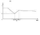
- FIG. 6is a graph illustrating the temporal transition of the worker's safety work continuity S.
- the horizontal axis of the graph of FIG. 6indicates the time t.
- the time at the start of operationis set to 0.
- the vertical axis of the graph of FIG. 6shows the safety work continuity S.
- the safety work continuity Sstarts to decrease and becomes equal to the threshold value ⁇ at time t0.
- the control unit 10detects that the safety work continuity S is equal to or less than the threshold value ⁇ at time t0 (No in S6 of FIG. 4). Therefore, the process proceeds to step S7, and the control unit 10 that operates as the output control unit 14 performs intervention control. Intervention control is performed for a predetermined time ⁇ t.
- Intervention controlimproves the alertness of workers and increases the sustainability of safe work S.
- the control unit 10finishes the intervention control at the time t1 after the time t0 by ⁇ t.
- the display system 1has a camera 3 that captures an image including the face of the worker and generates image data, and a control that determines the safety work continuity degree S based on the image data.
- a unit 10 and a display 4 for displaying the safety work continuity degree Sare provided.
- the control unit 10acquires image data from the camera 3, detects the position of the worker's organ based on the acquired image data, and based on the detected position of the worker's organ, the safety work continuity S May be determined.
- the display system 1displays the safety work continuity degree S on the display 4.
- the display 4merely displays the safety work continuity degree S and does not act on the operator with sound or vibration or request any action of the operator, the operator is not uncomfortable.
- the workercan say that the safety work continuity S is lower than that at the start of operation, or the safety work continuability S is lowered to near a predetermined threshold value. If this is known, it can be expected that the safety work continuity S of the worker will increase due to the fact that the knowledge itself awakens drowsiness.
- the control unit 10may detect the position of the pupil as the position of the worker's organ. Further, the control unit 10 may detect the positions of the upper eyelid and the lower eyelid as the positions of the organs of the worker.
- the range of movement of the position of the pupil of the workerbecomes narrow, or the speed of the movement or saccade becomes small.
- the distance between the upper eyelid and the lower eyelid of the operatorbecomes smaller. That is, the eyelids are about to close. Therefore, by using the position of the pupil or the position of the upper eyelid and the lower eyelid, the safety work continuity degree S can be calculated accurately.
- control unit 10When the control unit 10 detects that the safety work continuity S is equal to or less than a predetermined threshold value ⁇ , the control unit 10 controls the vibration device 5 and / or the speaker 6 attached to the seat to participate in the operator. Intervention actions may be performed.
- the intervention actioncan be expected to increase the safety work continuity S that has fallen below the threshold value ⁇ , and can reduce the risk of collision accidents and the like.
- FIG. 7is a flowchart showing the operation flow of the display system according to the first modification. Since steps S1 to S5 shown in FIG. 7 are the same as steps S1 to S5 of the operation flow of the display system 1 shown in FIG. 4, the description thereof will be omitted.
- step S5the control unit 10 detects whether or not the safety work continuity S is greater than the predetermined first threshold value ⁇ 1 (S61). When it is detected that the safety work continuability S is larger than the first threshold value ⁇ 1 (Yes in S61), the control unit 10 ends a series of processes shown in FIG. 7.
- the control unit 10determines whether or not the safety work continuity degree S is larger than the predetermined second threshold value ⁇ 2. Is detected (S62).
- the second threshold value ⁇ 2is smaller than the first threshold value ⁇ 1.
- the control unit 10 operating as the output control unit 14performs intervention control (S7).
- the control unit 10When it is detected that the safety work continuability S is larger than the second threshold value ⁇ 2 (Yes in S62), has the control unit 10 performed a confirmation operation to confirm the display 4 within the predetermined period T? Detects whether or not (S63).
- the confirmation operationfor example, the information on the eye movement of the operator measured in step S3 is used.
- the control unit 10detects that the operator has performed the confirmation operation when the operator's line of sight is directed toward the display 4.
- the period Tis measured as, for example, the time from the time when the line of sight of the operator turns to the direction of the display 4 and then the line of sight deviates from the display 4.
- the period Tmay be measured as the time from the end of the intervention control when the intervention control is performed.
- the period Tmay be, for example, a period from a time point earlier by a predetermined time from the present to the present.
- step S63When it is detected in step S63 that the worker has not performed the confirmation operation within the period T (No in S63), the control unit 10 operating as the output control unit 14 performs intervention control (S7). When it is detected in step S63 that the operator has performed the confirmation operation within the period T (Yes in S63), the control unit 10 ends the series of processes shown in FIG. 7.
- FIG. 8is a graph illustrating the temporal transition of the worker's safety work continuity S.
- the safety work continuity Sstarts to decrease and becomes equal to the second threshold value ⁇ 2 at time t0.
- the control unit 10detects that the safety work continuity S is equal to or less than the first threshold value ⁇ 1 (No in S61 of FIG. 7) and detects that the safety work continuity S is not less than or equal to the second threshold value ⁇ 2 (No). No) in S62 of FIG. Therefore, the process proceeds to step S7, and the control unit 10 that operates as the output control unit 14 performs intervention control. Intervention control is performed for a predetermined time ⁇ t.
- Intervention controlimproves the alertness of workers and increases the sustainability of safe work S.
- the control unit 10finishes the intervention control at the time t1 after the time t0 by ⁇ t.
- the control unit 10detects that the safety work continuity S is equal to or less than the first threshold value ⁇ 1 (No in S61 of FIG. 7) and is larger than the second threshold value ⁇ 2. (Yes in S62 of FIG. 7).
- the control unit 10detects that the operator has not performed the confirmation operation within the period T (No in S63). Therefore, the process proceeds to step S7, and the control unit 10 that operates as the output control unit 14 performs intervention control.
- the control unit 10finishes the intervention control at the time t3 after the time t2 by ⁇ t.
- intervention controlis not performed when the safety work continuity S is larger than the first threshold value ⁇ 1.
- intervention controlis performed when the operator does not perform the confirmation operation within the period T.
- the operatorcan continue safe work on the display 4 for a certain long period of time while preventing the frequent occurrence of intervention control and suppressing the occurrence of discomfort of the operator. If the display of S is not seen, intervention control is performed. As a result, the operator is urged to check the display 4, and by checking the safety work continuity S, the effect of maintaining or increasing the safety work continuity S can be effectively exerted.
- the safety work continuity Sis calculated based on the measurement result of at least one of the worker's eye movement, eye contour, and facial expression information.
- the information used to calculate the safety work continuity Sis not limited to these.
- the control unit 10may calculate the safety work continuity degree S based on biological information such as blood pressure, heart rate, body temperature, respiratory rate, brain wave, and sweating amount of the worker.
- FIG. 9is a diagram illustrating the configuration of the display system 101 according to such a second modification.
- the display system 101is a biological information measuring unit 30 that measures biological information such as a worker's blood pressure, heart rate, body temperature, respiratory rate, brain wave, and sweating amount, and an input that inputs the measured biological information to the control unit 10.
- a unit 31is provided.
- the biological information measuring unit 30is, for example, a known vital sign measuring instrument.
- the input unit 31is an interface circuit that connects the display system 101 and an external device such as the biological information measurement unit 30.
- control unit 10acquires information such as the speed, acceleration, and angular velocity of the vehicle 2 measured by using the sensor via the input unit 31, and calculates the safety work continuity degree S based on the acquired information. You may.
- the safety work continuity degree Smay be calculated by combining the eye movement, eye contour, and facial expression information of the above embodiment with the biological information and vehicle information described in the second modification. Further, for example, when the safety work continuity degree S is calculated by combining these information, each information may be weighted according to the personality of the worker, the chronic disease, the driving suitability, and the like.
- FIG. 10is a flowchart showing the operation flow of the display system according to the third modification.
- step S6 for detecting whether or not the safety work continuity degree S is larger than the predetermined threshold value ⁇Is executed.
- the control unit 10displays the safety work continuity S calculated in step S4 on the display 4 (S5).
- the control unit 10vibrates the vibrating device 5 (see FIG. 2) attached to the seat, and / or the calculated safety work continuity.
- the control for outputting the sound corresponding to S to the speaker 6has been described.
- intervention controlis not limited to these.
- the control unit 10may be configured to be able to control the steering and brakes of the vehicle 2, and may perform automatic driving control and automatic braking control as intervention control.
- the safety work continuity Sis equal to or less than the threshold value ⁇ (No in S6)
- automatic driving control and automatic braking controlcan be performed to prevent an accident.
- the display system 1 applied to in-vehicle usehas been described.
- the present disclosureis not limited to this.
- the display system 1may be used in a factory.
- the factory worker who assembles and packs the product in the factorycan confirm the safety work continuity degree S displayed on the display 4 of the display system 1. it can.
- the display system 1may be used in an office or the like.
- a desk worker who performs desk work in an office and a desk worker who performs desk work at home, or a worker who continues to work in the same placecan continue the safe work displayed on the display 4 of the display system 1.
- the possibility Scan be confirmed.
- the display system 1allows workers such as factory workers and desk workers to know that the safety work continuability S has decreased, the workers consciously work with caution and take a break by themselves. It is possible to try to increase the safety work continuity S by taking measures such as putting in or switching to a different work. This makes it possible to reduce the risk of mistakes in factories, accidents, mistakes in desk work, and the like.
- the display system 1may include a control unit that controls the work line of the factory. As a result, the display system 1 can prevent the occurrence of mistakes and accidents by stopping the work line of the factory when the safety work continuity S is lowered. In addition, the display system 1 may notify the factory manager, collaborators, and medical workers such as industrial physicians and nurses when the safety work continuity S is lowered. As a result, these persons can take measures such as reviewing the work plan. In this way, the occurrence of mistakes and accidents can be prevented.
- the safety work continuity degree Sis displayed on the display 4 of the display system 1.
- the display 4may display a diagram, illumination, or the like according to the safety work continuity S.
- the intervention actionmay be an alarm sound according to the safety work continuity S, an announcement such as prompting a break, a seat vibration, or the like.
- the display system 1may read out the safety work continuity degree S as an intervention operation.
- the display system 1may display a warning image on the monitor screen as an intervention operation.
- the display system 1may be in a state where the application cannot be operated until the safety work continuity S is improved.
- the display system (1,101) of the first aspectis Input section (31) for inputting information on safety work continuity, A control unit (10) that determines the safety work continuity based on the information on the safety work continuity, and a control unit (10).
- a display unit (4) for displaying the safety work continuityis provided.
- the display system (1) of the second aspectcaptures an image including a human face as information regarding the continuity of safe work, and generates image data (3).
- the control unit (10)acquires the image data from the image pickup unit (3), and detects and detects at least one of the position and the moving speed of the human organ based on the acquired image data.
- the safety work continuityis determined based on the position of at least one of the person's organs and movement speed.
- control unit (10)detects the position or movement speed of the pupil as the position or movement speed of the human organ.
- control unit (10)determines the position of the upper eyelid and the lower eyelid as the position or the moving speed of the human organ. Is detected.
- the display system (1,101) of the fifth aspectfurther includes an intervention unit (5, 6) that performs an intervention operation involving an operator in the display system of any of the second to fourth aspects.
- the control unit (10)further detects a confirmation operation in which the person looks at the display unit based on the detected position of the organ of the person. If the control unit (10) does not detect the confirmation operation within a predetermined period, the control unit (10) causes the intervention unit (5, 6) to perform the intervention operation.
- the control unit (10)measures the line of sight of the person based on the detected position of the organ of the person.
- the confirmation operationis detected when the line of sight faces the direction of the display unit.
- the display system (1,101) of the seventh aspectfurther includes an intervention unit (5, 6) that performs an intervention operation involving an operator in the display system of any one of the first to sixth aspects.
- an intervention unit (5, 6)that performs an intervention operation involving an operator in the display system of any one of the first to sixth aspects.
- the control unit (10)receives information on the sustainability of safe work (S1), and The safety work continuity is determined based on the information on the safety work continuity (S4).
- the display unit (4)is displayed with the safety work continuability (S5).
- the ninth aspectis a program for causing the control unit (10) to execute the display method of the eighth aspect.
Landscapes
- Physics & Mathematics (AREA)
- General Physics & Mathematics (AREA)
- Traffic Control Systems (AREA)
- User Interface Of Digital Computer (AREA)
- Emergency Alarm Devices (AREA)
Abstract
Description
Translated fromJapanese本開示は、表示システム、表示方法、及びプログラムに関する。This disclosure relates to display systems, display methods, and programs.
特許文献1には、ドライバーの覚醒度が、居眠り運転状態よりも高く通常状態よりも低い漫然状態であると判定した際に、ドライバーの覚醒度を改善するアプリケーションを実行手段に実行させる制御手段を備える覚醒度改善装置が開示されている。これにより、ドライバーの覚醒度を向上させることができる。
しかしながら、特許文献1に開示された装置では、ドライバーの覚醒度が表示されず、ドライバーは、ドライバーに関与するアプリケーション等の介入動作が実行されるまで、覚醒度が低下していることを知ることができない。また、漫然状態という概念は広く、特許文献1に開示された装置では、ドライバーが漫然状態であるものの通常状態に近い覚醒状態である場合においても介入動作が実行され、介入動作が頻発される。このような介入動作の頻発は、ドライバーに不快感を与える。However, in the device disclosed in
本開示の目的は、作業者に与える不快感を低減しつつ、作業者に安全作業継続可能度の低下を知らせることができる表示システム、表示方法、及びプログラムを提供することにある。An object of the present disclosure is to provide a display system, a display method, and a program capable of notifying a worker of a decrease in the continuity of safe work while reducing discomfort to the worker.
本開示の一態様は、安全作業継続可能度に関する情報を入力する入力部と、安全作業継続可能度に関する情報に基づいて安全作業継続可能度を決定する制御部と、安全作業継続可能度を表示する表示部と、を備える表示システムを提供する。One aspect of the present disclosure displays an input unit for inputting information on the continuity of safe work, a control unit for determining the continuity of safe work based on the information on the continuity of safe work, and a continuity of safe work. Provided is a display unit including a display unit.
本開示の他の態様は、制御部が、安全作業継続可能度に関する情報を受信し、前記安全作業継続可能度に関する情報に基づいて前記安全作業継続可能度を決定し、表示部に、前記安全作業継続可能度を表示させる、表示方法を提供する。In another aspect of the present disclosure, the control unit receives information on the safety work continuity, determines the safety work continuity based on the information on the safety work continuity, and displays the safety on the display unit. Provide a display method for displaying work continuity.
本開示に係る表示システム、表示方法、及びプログラムにより、作業者に与える不快感を低減しつつ、作業者に安全作業継続可能度の低下を知らせることができる。The display system, display method, and program according to the present disclosure can reduce the discomfort given to the worker and notify the worker of the decrease in the continuity of safe work.
以下、添付の図面を参照して本開示に係る表示システムの実施形態を説明する。なお、以下の各実施形態において、同一又は同様の構成要素については同一の符号を付している。Hereinafter, embodiments of the display system according to the present disclosure will be described with reference to the attached drawings. In each of the following embodiments, the same or similar components are designated by the same reference numerals.
[1.適用例]
本開示に係る表示システムを適用可能な一例について、図1を参照して説明する。図1は、本開示に係る表示システム1の適用例を説明するための模式図である。[1. Application example]
An example to which the display system according to the present disclosure can be applied will be described with reference to FIG. FIG. 1 is a schematic diagram for explaining an application example of the
本開示に係る表示システム1は、例えば車載用途に適用可能であり、車両2に搭載される。表示システム1は、例えば、カメラ3と、ディスプレイ4と、制御部10とを備える。The
カメラ3は、本開示の「撮像部」の一例である。カメラ3は、作業者の顔を撮像する。作業者は、例えば車両2の運転者である。カメラ3によって撮像された画像データは、本開示の「安全作業継続可能度に関する情報」の一例である。例えば、カメラ3は、ステアリングコラムカバー、ダッシュボード、及びルームミラー付近等の作業者の前方に取り付けられる。カメラ3の位置はこれに限定されず、作業者の顔を撮像できる位置であればよい。例えば、カメラ3は、眼鏡型のカメラや、作業者の頭部に装着されたヘッドマウント型のカメラであってもよい。The
制御部10は、例えばCPUを含む情報処理装置である。制御部10は、カメラ3によって撮像された画像に基づいて、作業者の顔、目、皮膚等の器官の位置、及びそれらの動きを測定する。例えば、制御部10は、作業者の眼球運動、眼輪郭等を測定する。The
ここで、器官は、組織の集まりであって、特定の機能を有するものを含む。例えば、器官は、目、鼻、口、及び耳を含む。器官は、皮膚を含んでもよい。顔全体が器官に含まれてもよい。目に関して、器官は、例えば、眼球及びその周りの上眼瞼、下眼瞼、外眼角、及び内眼角等を含む。眼球に関して、器官は、例えば、瞳孔、虹彩、角膜、網膜、及び水晶体等を含む。Here, an organ includes a group of tissues having a specific function. For example, organs include eyes, nose, mouth, and ears. Organs may include skin. The entire face may be included in the organ. With respect to the eye, organs include, for example, the levator palpebra, the lower eyelid, the outer canthus, the inner canthus, etc. in and around the eyeball. With respect to the eye, organs include, for example, the pupil, iris, cornea, retina, and lens.
次に、制御部10は、測定結果に基づいて、作業者が事故を起こさずに運転を継続できる可能性を表す指標を示す安全作業継続可能度Sを算出する。安全作業継続可能度Sは、作業者の眠気の程度、漫然の程度、及び疲労度等を総合的に判断して算出されてもよい。Next, the
算出された安全作業継続可能度Sは、ディスプレイ4に表示される。これにより、作業者は、ディスプレイ4に表示された安全作業継続可能度Sを確認することができる。例えば、作業者は、ディスプレイ4に表示された安全作業継続可能度Sを定期的に確認することにより、自己の安全作業継続可能度Sの推移を知ることができる。例えば、作業者に眠気が生じ、安全作業継続可能度Sが運転開始時より下がった場合、表示システム1により、作業者は、安全作業継続可能度Sの低下を認識することができる。ディスプレイ4の表示により安全作業継続可能度Sの低下を認識することで、警告音等の作業者に関与する介入動作がなくても、作業者の安全作業継続可能度Sが増加することがあり得る。The calculated safety work continuity S is displayed on the
また、作業者が自己の安全作業継続可能度Sの低下を認識した場合、自発的に眠気を解消する等の動作を行い、安全作業継続可能度Sを増加させるよう試みることができる。In addition, when the worker recognizes that the safety work continuity S is lowered, he / she can voluntarily take actions such as relieving drowsiness and try to increase the safety work continuity S.
このように、ディスプレイ4には、原則として、常に安全作業継続可能度Sが表示される。安全作業継続可能度Sが予め定められた閾値以下となった場合、制御部10は、作業者に関与する介入動作を行うための介入制御を行う。介入動作は、作業者の五官に直接的又は間接的に働きかける動作を含む。例えば、制御部10は、座席に取り付けられた振動装置を振動させ、及び/又は、算出された安全作業継続可能度Sに応じた音声をスピーカに出力させる。これにより、例えば作業者の覚醒度が向上し、漫然状態、眠気状態等が解消され、ひいては安全作業継続可能度Sが増加する。上記の振動装置及びスピーカは、本開示の「介入部」の一例である。In this way, as a general rule, the
このような介入動作を行う介入部は、例えば、空調システムを含む。空調システムは、作業者の周囲の空気の温度、湿度、及び気流等を調整するシステムである。例えば、制御部10は、空調システムを制御し、作業者の周囲の温度を下げたり、作業者に風を当てたりする。これにより、例えば作業者の覚醒度が向上し、漫然状態、眠気状態等が解消され、ひいては安全作業継続可能度Sが増加する。The intervention unit that performs such an intervention operation includes, for example, an air conditioning system. The air conditioning system is a system that regulates the temperature, humidity, air flow, etc. of the air around the worker. For example, the
介入部は、例えば、照明システムを含む。照明システムは、例えば照度や作業者の周囲の空間の明るさを調節する光源装置である。例えば、制御部10は、照明システムを制御し、照度を上げたり、光源を点滅させたりする。これにより、例えば作業者の覚醒度が向上し、漫然状態、眠気状態等が解消され、ひいては安全作業継続可能度Sが増加する。The intervention section includes, for example, a lighting system. The lighting system is, for example, a light source device that adjusts the illuminance and the brightness of the space around the worker. For example, the
このような介入動作は、作業者が眠気を帯びた状態の場合には事故等を防止するために有効であるが、作業者が眠気を帯びていない等、通常状態に近い状態である場合に頻発されると、作業者に不快感を生じさせる。また、このような介入動作を止めるために作業者の行動を必要とすると煩瑣であり、運転に危険が生じ得る。本開示の表示システム1では、安全作業継続可能度Sが閾値より大きく、作業者の状態が通常状態に近い状態である場合には、ディスプレイ4に安全作業継続可能度Sを表示するに止め、介入動作を行わない。したがって、表示システム1は、作業者に与える不快感を低減しつつ、作業者に安全作業継続可能度の低下を知らせることができる。Such an intervention action is effective for preventing an accident or the like when the worker is in a drowsy state, but is in a state close to a normal state such as when the worker is not drowsy. When it occurs frequently, it causes discomfort to the operator. In addition, it is troublesome to require the action of the operator to stop such an intervention operation, and driving may be dangerous. In the
[2.構成例]
以下、本開示の実施形態に係る表示システム1の構成例について説明する。[2. Configuration example]
Hereinafter, a configuration example of the
図2は、表示システム1の構成を例示するブロック図である。表示システム1は、図2に例示するように、カメラ3と、ディスプレイ4と、制御部10とを備える。表示システム1は、記憶部20を更に備えてもよい。表示システム1は、出力装置として、振動装置5とスピーカ6とを更に備えてもよい。FIG. 2 is a block diagram illustrating the configuration of the
カメラ3は、作業者の顔、目その他の器官を撮像して撮像画像を形成する撮像装置である。カメラ3は、例えば、CMOS(Complementary MOS)、CCD(Charge Coupled Device)等の固体撮像素子によって撮像画像を形成するカメラである。The
表示システム1は、作業者の顔に向けて赤外線を照射する図示しない赤外線照射器を備えてもよい。この場合、カメラ3は、赤外域に感度を有する赤外線カメラであってもよい。The
ディスプレイ4は、例えば液晶ディスプレイ、有機ELディスプレイ、及びプロジェクタ等の表示装置である。図3は、ディスプレイ4の例を示す図である。言い換えれば、図3は、安全作業継続可能度Sを示す画像が表示される場所の例を示す図である。安全作業継続可能度Sを示す画像は、例えば車両2のルームミラー40、ヘッドアップディスプレイ41、メータパネル42、及びフロントガラス43等に表示される。また、安全作業継続可能度Sを示す画像は、図示しないカーナビゲーション機器のディスプレイに表示されてもよい。The
図2に戻り、制御部10は、CPU(Central Processing Unit)、RAM(Random Access Memory)、ROM(Read Only Memory)等を含み、情報処理に応じて表示システム1の各構成要素の制御を行う。制御部10は、例えば、ECU(電子制御ユニット)により構成される。制御部10は、例えば、RAMに展開されたプログラムをCPUにより解釈及び実行する。このように実現されるソフトウェアモジュールとして、制御部10は、例えば、画像処理部11、測定部12、安全作業継続可能度算出部13、及び出力制御部14を備える。Returning to FIG. 2, the
記憶部20は、コンピュータその他装置、機械等が記録されたプログラム等の情報を読み取り可能なように、当該プログラム等の情報を、電気的、磁気的、光学的、機械的又は化学的作用によって蓄積する媒体である。記憶部20は、例えば、ハードディスクドライブ、ソリッドステートドライブ等の補助記憶装置を含む。記憶部20には、例えば、後述の安全作業継続可能度算出テーブル21が格納される。The
記憶部20は、表示システム1とネットワークを介して通信可能なサーバ等の外部装置の中に設けられてもよい。The
振動装置5は、例えば、作業者が座る座席に取り付けられ、作業者に振動を伝えることができる。あるいは、振動装置5は、ステアリングハンドルに取り付けられ、作業者の手に振動を伝えてもよい。例えば、出力制御部14として動作する制御部10は、算出された安全作業継続可能度Sに応じて、振動装置5を振動させる。これにより、例えば作業者の覚醒度が向上し、漫然状態、眠気状態等が解消される。このように、振動装置5は、安全作業継続可能度Sを増加させるように動作することができる。The
スピーカ6は、音声によって、作業者に各種情報を報知する音声出力装置である。例えば、出力制御部14として動作する制御部10は、算出された安全作業継続可能度Sに応じた音声を、スピーカ6に出力させる。スピーカ6が出力する音声は、警告音、休憩を促す等の警告アナウンス、及び安全作業継続可能度Sの読み上げ等を含む。例えば、スピーカ6から出力された警告音によって、作業者の覚醒度が向上し、漫然状態、眠気状態等が解消される。このように、スピーカ6は、安全作業継続可能度Sを増加させるように動作することができる。The
[3.動作例]
以下、表示システム1の動作例について説明する。図4は、表示システム1の動作の流れを例示するフローチャートである。図4のフローチャートの各処理は、表示システム1の制御部10によって一定の間隔で繰り返し実行される。[3. Operation example]
An operation example of the
まず、制御部10は、カメラ3によって撮像された作業者の顔画像を含む画像を取得する(S1)。First, the
次に、画像処理部11として動作する制御部10は、取得した画像に対して画像処理を行い、作業者の器官の位置を検出する(S2)。Next, the
例えば、ステップS2において、制御部10は、作業者の瞳孔、上眼瞼、及び下眼瞼等の位置を検出する。なお、図4のフローチャートでは省略するが、制御部10は、作業者の器官の位置を検出できなかった場合は、一連の処理を終了する。For example, in step S2, the
次に、測定部12として動作する制御部10は、作業者の眼球運動、眼輪郭、及び表情情報のうちの少なくとも1つを測定する(S3)。ここで、眼球運動は、例えば瞳孔又は視線の位置及び移動速度、前庭動眼反射(Vestibulo-ocular reflex、VOR)、並びに固視及びサッケードの回数等を含む。眼球運動は、画像解析や角膜反射法等の公知の方法によって測定される。眼輪郭は、例えば上眼瞼及び下眼瞼の位置、上眼瞼から下眼瞼までの距離、開眼度、上眼瞼及び下眼瞼の移動速度、並びに瞬目の速度及び回数等を含む情報である。表情情報は、例えば、眼輪郭、口の形状、及び頬の筋肉の位置等の顔の特徴量に基づいて推定される情報である。顔の特徴量に基づく表情測定には、公知の方法が適用されてもよい。Next, the
次に、安全作業継続可能度算出部13として動作する制御部10は、ステップS3の測定結果に基づいて、安全作業継続可能度Sを算出する(S4)。Next, the
安全作業継続可能度Sは、作業者が事故を起こさずに運転を継続できる可能性を表す指標である。安全作業継続可能度Sは、例えば0~1の範囲の値を取り、値が大きいほど作業者が事故を起こさずに運転を継続できる可能性が高いことを意味する。The safety work continuity S is an index showing the possibility that the worker can continue driving without causing an accident. The safety work continuity S is, for example, a value in the range of 0 to 1, and the larger the value, the higher the possibility that the worker can continue the operation without causing an accident.
安全作業継続可能度算出部13として動作する制御部10は、例えば、作業者の眼球運動、眼輪郭、及び表情情報のうちの少なくとも1つに基づいて、安全作業継続可能度Sを算出する。安全作業継続可能度Sは、これらのうちの2つ以上を組み合わせて算出されてもよい。The
制御部10は、例えば、ステップS3の測定結果をキーとして記憶部20の安全作業継続可能度算出テーブル21を検索し、キーに対応する安全作業継続可能度Sの値を、安全作業継続可能度算出テーブル21から抽出して取得する。For example, the
安全作業継続可能度算出テーブル21は、例えば多数の作業者の過去の眼球運動、眼輪郭、及び表情情報等の測定結果を、当該作業者の測定時の安全作業継続可能度Sに関連付けることによって作成される。あるいは、安全作業継続可能度算出テーブル21は、理論や経験則等に基づいて人的に作成されてもよい。The safety work continuity calculation table 21 is obtained by associating the measurement results of the past eye movements, eye contours, facial expression information, etc. of a large number of workers with the safety work continuity S of the workers at the time of measurement. Will be created. Alternatively, the safety work continuity calculation table 21 may be created humanly based on theory, empirical rules, or the like.
例えば、安全作業継続可能度Sは、作業者の視線又は瞳孔の移動範囲が大きいほど高くなるように算出される。あるいは、安全作業継続可能度Sは、作業者の視線又は瞳孔の移動の速さが大きいほど高くなるように算出されてもよい。安全作業継続可能度Sは、作業者の視線又は瞳孔の移動範囲と移動の速さとを組み合わせて算出されてもよい。For example, the safety work continuity S is calculated so that the larger the range of movement of the worker's line of sight or pupil, the higher the degree. Alternatively, the safety work continuity S may be calculated so that the speed of movement of the line of sight or pupil of the worker increases. The safety work continuity S may be calculated by combining the movement range of the operator's line of sight or pupil and the speed of movement.
上記のような算出方法と異なり、又は、上記のような算出方法と組み合わせて、安全作業継続可能度Sは、例えば、瞬目の速さが大きいほど高くなるように算出される。あるいは、安全作業継続可能度Sは、開眼度が大きいほど高くなるように算出されてもよい。安全作業継続可能度Sは、瞬目の速さと開眼度とを組み合わせて算出されてもよい。Different from the above calculation method, or in combination with the above calculation method, the safety work continuity S is calculated so as to increase, for example, as the speed of the blink increases. Alternatively, the safety work continuity degree S may be calculated so as to increase as the degree of eye opening increases. The safety work continuity S may be calculated by combining the speed of blinking and the degree of eye opening.
上記のような算出方法と異なり、又は、上記のような算出方法と組み合わせて、制御部10は、ステップS3の測定結果に基づいて、作業者の眠気、疲労、及び漫然等の程度を総合的に判断して安全作業継続可能度Sを算出してもよい。例えば、安全作業継続可能度Sは、作業者が居眠り運転状態や眠気を帯びた状態、アルコールや疾病等の影響により正常な運転が困難である危険運転状態、疲労が蓄積した状態、漫然状態であるとき、低い値を取る。特に、居眠り運転状態や危険運転状態においては、安全作業継続可能度Sは低い値となり、例えば0に近い値となる。Different from the above calculation method, or in combination with the above calculation method, the
次に、制御部10は、ステップS4で算出された安全作業継続可能度Sを、ディスプレイ4に表示する(S5)。これにより、作業者は、ディスプレイ4に表示された安全作業継続可能度Sを確認することができる。ディスプレイ4には、安全作業継続可能度Sの値そのものが表示されてもよいし、図5に示したような安全作業継続可能度Sのメータが表示されてもよい。Next, the
次に、制御部10は、安全作業継続可能度Sが予め定められた閾値αより大きいか否かを検知する(S6)。安全作業継続可能度Sが閾値αより大きいことを検知した場合(S6でYes)、制御部10は、図4に示した一連の処理を終了する。Next, the
安全作業継続可能度Sが閾値α以下であることを検知した場合(S6でNo)、出力制御部14として動作する制御部10は、介入制御を行う(S7)。介入制御は、安全作業継続可能度Sを増加させるために作業者に関与する介入動作を行うための制御である。例えば、制御部10は、介入制御として、座席に取り付けられた振動装置5(図2参照)を振動させ、及び/又は、算出された安全作業継続可能度Sに応じた音声をスピーカ6に出力させる。これにより、例えば作業者の覚醒度が向上し、漫然状態、眠気状態等が解消され、ひいては安全作業継続可能度Sが増加する。When it is detected that the safety work continuability S is equal to or less than the threshold value α (No in S6), the
図6は、作業者の安全作業継続可能度Sの時間的な推移を例示するグラフである。図6のグラフの横軸は時刻tを示している。運転開始時の時刻を0とする。図6のグラフの縦軸は安全作業継続可能度Sを示している。運転開始時から時間が経過すると、安全作業継続可能度Sが低下し始め、時刻t0で閾値αに等しくなっている。制御部10は、時刻t0において、安全作業継続可能度Sが閾値α以下であることを検知する(図4のS6でNo)。したがって、ステップS7に進み、出力制御部14として動作する制御部10は、介入制御を行う。介入制御は、予め定められた時間Δtだけ行われる。FIG. 6 is a graph illustrating the temporal transition of the worker's safety work continuity S. The horizontal axis of the graph of FIG. 6 indicates the time t. The time at the start of operation is set to 0. The vertical axis of the graph of FIG. 6 shows the safety work continuity S. When time elapses from the start of operation, the safety work continuity S starts to decrease and becomes equal to the threshold value α at time t0. The
介入制御により、作業者の覚醒度が向上するなどして、安全作業継続可能度Sが増加する。制御部10は、時刻t0からΔt後の時刻t1に介入制御を終える。Intervention control improves the alertness of workers and increases the sustainability of safe work S. The
[4.まとめ]
以上のように、本実施形態に係る表示システム1は、作業者の顔を含む画像を撮像し、画像データを生成するカメラ3と、画像データに基づいて安全作業継続可能度Sを決定する制御部10と、安全作業継続可能度Sを表示するディスプレイ4と、を備える。[4. Summary]
As described above, the
制御部10は、カメラ3から画像データを取得し、取得した画像データに基づいて、作業者の器官の位置を検出し、検出した作業者の器官の位置に基づいて、安全作業継続可能度Sを決定してもよい。The
このような構成により、表示システム1は、ディスプレイ4に安全作業継続可能度Sを表示する。これにより、作業者に安全作業継続可能度Sの低下を知らせることができる。ディスプレイ4に安全作業継続可能度Sを表示させるに過ぎず、作業者に音や振動で働きかけたり、作業者の何らかの動作を要求することはないため、作業者に不快感を与えることはない。また、安全作業継続可能度S表示するだけでも、作業者が、安全作業継続可能度Sが運転開始時より低下したこと、又は、安全作業継続可能度Sが予め定められた閾値付近まで低下したことを知った場合、知ったこと自体により眠気が覚めるなどして、作業者の安全作業継続可能度Sが増加することが期待できる。With such a configuration, the
制御部10は、作業者の器官の位置として、瞳孔の位置を検出してもよい。また、制御部10は、作業者の器官の位置として、上眼瞼及び下眼瞼の位置を検出してもよい。The
例えば、眠気状態に陥ると、作業者の瞳孔の位置の移動範囲が狭くなり、又はその移動若しくはサッケードの速さが小さくなることが知られている。また、眠気状態に陥ると、例えば作業者の上眼瞼と下眼瞼との距離が小さくなる。すなわち、瞼が閉じかかった状態になる。したがって、瞳孔の位置、又は上眼瞼及び下眼瞼の位置を用いることで、精度良く安全作業継続可能度Sを算出できる。For example, it is known that when a person falls into a drowsy state, the range of movement of the position of the pupil of the worker becomes narrow, or the speed of the movement or saccade becomes small. In addition, when a person falls into a drowsy state, for example, the distance between the upper eyelid and the lower eyelid of the operator becomes smaller. That is, the eyelids are about to close. Therefore, by using the position of the pupil or the position of the upper eyelid and the lower eyelid, the safety work continuity degree S can be calculated accurately.
制御部10は、安全作業継続可能度Sが予め定められた閾値α以下であることを検知した場合、座席に取り付けられた振動装置5及び/又はスピーカ6を制御して、作業者に関与する介入動作を行ってもよい。When the
介入動作により、閾値α以下に下がった安全作業継続可能度Sを増加させることが期待でき、衝突事故等の危険を低減させることができる。The intervention action can be expected to increase the safety work continuity S that has fallen below the threshold value α, and can reduce the risk of collision accidents and the like.
[5.変形例]
以上、本開示の実施形態を詳細に説明したが、前述までの説明はあらゆる点において本開示の例示に過ぎない。本開示の範囲を逸脱することなく種々の改良や変形を行うことができる。例えば、以下のような変更が可能である。なお、以下では、上記実施形態と同様の構成要素に関しては同様の符号を用い、上記実施形態と同様の点については、適宜説明を省略する。以下の変形例は適宜組み合わせることができる。[5. Modification example]
Although the embodiments of the present disclosure have been described in detail above, the above description is merely an example of the present disclosure in all respects. Various improvements and modifications can be made without departing from the scope of the present disclosure. For example, the following changes can be made. In the following, the same reference numerals will be used for the same components as those in the above embodiment, and the same points as in the above embodiment will be omitted as appropriate. The following modifications can be combined as appropriate.
[5-1.第1変形例]
上記の実施形態では、図4に示したように、安全作業継続可能度Sが閾値α以下であることを検知した場合(S6でNo)に制御部10が介入制御を行う例について説明した。しかしながら、介入制御が実行されるのはこのような場合に限定されない。[5-1. First modification]
In the above embodiment, as shown in FIG. 4, an example in which the
図7は、第1変形例に係る表示システムの動作の流れを示すフローチャートである。図7に示したステップS1~S5は、図4に示した表示システム1の動作の流れのステップS1~S5と同様であるため説明を省略する。FIG. 7 is a flowchart showing the operation flow of the display system according to the first modification. Since steps S1 to S5 shown in FIG. 7 are the same as steps S1 to S5 of the operation flow of the
ステップS5の後、制御部10は、安全作業継続可能度Sが予め定められた第1閾値α1より大きいか否かを検知する(S61)。安全作業継続可能度Sが第1閾値α1より大きいことを検知した場合(S61でYes)、制御部10は、図7に示した一連の処理を終了する。After step S5, the
安全作業継続可能度Sが第1閾値α1以下であることを検知した場合(S61でNo)、制御部10は、安全作業継続可能度Sが予め定められた第2閾値α2より大きいか否かを検知する(S62)。第2閾値α2は、第1閾値α1より小さい。安全作業継続可能度Sが第2閾値α2以下であることを検知した場合(S62でNo)、出力制御部14として動作する制御部10は、介入制御を行う(S7)。When it is detected that the safety work continuability S is equal to or less than the first threshold value α1 (No in S61), the
安全作業継続可能度Sが第2閾値α2より大きいことを検知した場合(S62でYes)、制御部10は、作業者が予め定められた期間T内にディスプレイ4を確認する確認動作を行ったか否かを検知する(S63)。確認動作を行ったか否かを検知するために、例えば、ステップS3で測定された作業者の眼球運動の情報が用いられる。例えば、制御部10は、作業者の視線がディスプレイ4の方向を向いた場合に作業者が確認動作を行ったことを検知する。When it is detected that the safety work continuability S is larger than the second threshold value α2 (Yes in S62), has the
期間Tは、例えば、作業者の視線がディスプレイ4の方向を向いた後に視線がディスプレイ4から外れた時点からの時間として計測される。あるいは、期間Tは、介入制御が行われた場合に、介入制御の終了時からの時間として計測されてもよい。期間Tは、例えば、現在から予め定められた時間だけ前の時点から、現在までの期間であってもよい。The period T is measured as, for example, the time from the time when the line of sight of the operator turns to the direction of the
ステップS63において作業者が期間T内に確認動作を行っていないことを検知した場合(S63でNo)、出力制御部14として動作する制御部10は、介入制御を行う(S7)。ステップS63において作業者が期間T内に確認動作を行ったことを検知した場合(S63でYes)、制御部10は、図7に示した一連の処理を終了する。When it is detected in step S63 that the worker has not performed the confirmation operation within the period T (No in S63), the
図8は、作業者の安全作業継続可能度Sの時間的な推移を例示するグラフである。運転開始時から時間が経過すると、安全作業継続可能度Sが低下し始め、時刻t0で第2閾値α2に等しくなっている。制御部10は、時刻t0において、安全作業継続可能度Sが第1閾値α1以下であることを検知し(図7のS61でNo)、かつ、第2閾値α2以下であることを検知する(図7のS62でNo)。したがって、ステップS7に進み、出力制御部14として動作する制御部10は、介入制御を行う。介入制御は、予め定められた時間Δtだけ行われる。FIG. 8 is a graph illustrating the temporal transition of the worker's safety work continuity S. When time has passed from the start of operation, the safety work continuity S starts to decrease and becomes equal to the second threshold value α2 at time t0. At time t0, the
介入制御により、作業者の覚醒度が向上するなどして、安全作業継続可能度Sが増加する。制御部10は、時刻t0からΔt後の時刻t1に介入制御を終える。Intervention control improves the alertness of workers and increases the sustainability of safe work S. The
その後、作業者が期間Tの間ディスプレイ4を確認しないまま、時刻t2に至ったとする。すると、時刻t2において、制御部10は、安全作業継続可能度Sが第1閾値α1以下であることを検知し(図7のS61でNo)、かつ、第2閾値α2より大きいことを検知する(図7のS62でYes)。次のステップS63では、制御部10は、作業者が期間T内に確認動作を行っていないことを検知する(S63でNo)。したがって、ステップS7に進み、出力制御部14として動作する制御部10は、介入制御を行う。制御部10は、時刻t2からΔt後の時刻t3に介入制御を終える。After that, it is assumed that the worker reaches the time t2 without checking the
このように、第1変形例に係る表示システムでは、安全作業継続可能度Sが第1閾値α1より大きい場合は介入制御を行わない。一方、第1閾値α1以下であり、かつ第2閾値α2より大きい場合には、作業者が期間T内に確認動作を行わなかった場合に介入制御を行う。このように、第1変形例に係る表示システムでは、介入制御の頻発を防止して作業者の不快感の発生を抑制しつつ、作業者が一定の長い時間ディスプレイ4上の安全作業継続可能度Sの表示を見なかった場合には介入制御を行う。これにより、作業者がディスプレイ4を確認するように促し、安全作業継続可能度Sを確認すること自体により安全作業継続可能度Sを維持又は増加させる効果を有効に発揮させることができる。As described above, in the display system according to the first modification, intervention control is not performed when the safety work continuity S is larger than the first threshold value α1. On the other hand, when it is equal to or less than the first threshold value α1 and larger than the second threshold value α2, intervention control is performed when the operator does not perform the confirmation operation within the period T. As described above, in the display system according to the first modification, the operator can continue safe work on the
[5-2.第2変形例]
上記の実施形態では、図4のステップS4に示したように、作業者の眼球運動、眼輪郭、及び表情情報のうちの少なくとも1つの測定結果に基づいて、安全作業継続可能度Sを算出する例について説明した。しかしながら、安全作業継続可能度Sを算出するために用いられる情報はこれらに限定されない。例えば、制御部10は、作業者の血圧、心拍数、体温、呼吸数、脳波、及び発汗量等の生体情報に基づいて安全作業継続可能度Sを算出してもよい。[5-2. Second variant]
In the above embodiment, as shown in step S4 of FIG. 4, the safety work continuity S is calculated based on the measurement result of at least one of the worker's eye movement, eye contour, and facial expression information. An example has been described. However, the information used to calculate the safety work continuity S is not limited to these. For example, the
図9は、このような第2変形例に係る表示システム101の構成を例示する図である。表示システム101は、作業者の血圧、心拍数、体温、呼吸数、脳波、及び発汗量等の生体情報を測定する生体情報測定部30と、測定された生体情報を制御部10に入力する入力部31とを備える。生体情報測定部30は、例えば公知のバイタルサイン計測器である。入力部31は、表示システム101と生体情報測定部30等の外部機器とを接続するインタフェース回路である。FIG. 9 is a diagram illustrating the configuration of the
また、制御部10は、センサを用いて測定された車両2の速度、加速度、及び角速度等の情報を入力部31を介して取得し、取得した情報に基づいて安全作業継続可能度Sを算出してもよい。Further, the
上記の実施形態の眼球運動、眼輪郭、及び表情情報と、第2変形例で述べた生体情報及び車両情報とを組み合わせて安全作業継続可能度Sが算出されてもよい。また、例えば、これらの情報を組み合わせて安全作業継続可能度Sを算出する場合には、作業者の性格、持病、及び運転適正等によって、各情報の重み付けが行われてもよい。The safety work continuity degree S may be calculated by combining the eye movement, eye contour, and facial expression information of the above embodiment with the biological information and vehicle information described in the second modification. Further, for example, when the safety work continuity degree S is calculated by combining these information, each information may be weighted according to the personality of the worker, the chronic disease, the driving suitability, and the like.
[5-3.第3変形例]
上記の実施形態では、図4のステップS5に示すように、算出された安全作業継続可能度Sが常にディスプレイ4に表示される例について説明した。しかしながら、介入制御が行われている間は、ディスプレイ4に安全作業継続可能度Sが表示されなくてもよい。図10は、このような第3変形例に係る表示システムの動作の流れを示すフローチャートである。[5-3. Third variant]
In the above embodiment, as shown in step S5 of FIG. 4, an example in which the calculated safety work sustainability S is always displayed on the
上記の実施形態と異なり、第3変形例では、安全作業継続可能度Sを算出するステップS4の後、安全作業継続可能度Sが予め定められた閾値αより大きいか否かを検知するステップS6が実行される。安全作業継続可能度Sが閾値αより大きいことを検知した場合(S6でYes)、制御部10は、ステップS4で算出された安全作業継続可能度Sを、ディスプレイ4に表示する(S5)。Unlike the above embodiment, in the third modification, after step S4 for calculating the safety work continuity degree S, step S6 for detecting whether or not the safety work continuity degree S is larger than the predetermined threshold value α. Is executed. When it is detected that the safety work continuity S is larger than the threshold value α (Yes in S6), the
[5-4.第4変形例]
上記の実施形態では、図4のステップS7の介入制御として、制御部10が、座席に取り付けられた振動装置5(図2参照)を振動させ、及び/又は、算出された安全作業継続可能度Sに応じた音声をスピーカ6に出力させる制御を説明した。しかしながら、介入制御はこれらに限定されない。例えば、制御部10は、車両2のステアリング及びブレーキ等を制御可能に構成され、介入制御として、自動運転制御及び自動ブレーキ制御を行ってもよい。これにより、安全作業継続可能度Sが閾値α以下であることを検知した場合(S6でNo)、自動運転制御及び自動ブレーキ制御を行って事故を防止することができる。[5-4. Fourth variant]
In the above embodiment, as the intervention control in step S7 of FIG. 4, the
[5-5.第5変形例]
上記の実施形態では、図1に示したように、車載用途に適用される表示システム1について説明した。しかしながら、本開示はこれに限定されない。例えば、表示システム1は、工場において利用されてもよい。具体的には、第5変形例においては、工場において製品の組立てや梱包等の作業を行なう工場作業者が、表示システム1のディスプレイ4に表示された安全作業継続可能度Sを確認することができる。[5-5. Fifth variant]
In the above embodiment, as shown in FIG. 1, the
また、表示システム1は、オフィス等において利用されてもよい。例えば、オフィスにおいてデスクワーク作業を行なうデスク作業者、及び在宅でデスクワーク作業を行うデスク作業者等の、同じ場所で作業を続けるような作業者が、表示システム1のディスプレイ4に表示された安全作業継続可能度Sを確認することができる。Further, the
例えば、表示システム1により工場作業者、デスク作業者等の作業者が安全作業継続可能度Sが低下したことを知ることができれば、作業者は、意識的に注意しながら作業する、自ら休憩を入れる、違う作業に切り替える等の対策を採って、安全作業継続可能度Sを増加させるよう試みることができる。これにより、工場におけるミス、事故、及びデスクワークにおけるミス等が生じるリスクを下げることができる。For example, if the
表示システム1は、工場の作業ラインを制御する制御部を備えてもよい。これにより、表示システム1は、安全作業継続可能度Sが低下した場合、工場の作業ラインを止めることにより、ミス及び事故の発生を防止することができる。また、表示システム1は、安全作業継続可能度Sが低下した場合、工場管理者、共同作業者、並びに産業医及び看護師等の医療従事者等に通知してもよい。これにより、これらの者が作業計画の見直しをする、といった対応を採ることができる。このようにして、ミス及び事故の発生を防止することができる。The
表示システム1のディスプレイ4には、例えば安全作業継続可能度Sが表示される。あるいは、ディスプレイ4には、安全作業継続可能度Sに準ずる図、イルミネーション等が表示されてもよい。For example, the safety work continuity degree S is displayed on the
介入動作は、安全作業継続可能度Sに応じた警報音、休憩を促す等のアナウンス、座席振動等であってもよい。また、表示システム1は、介入動作として、安全作業継続可能度Sを読み上げてもよい。作業者がモニタを利用して作業を行う場合、表示システム1は、介入動作としてモニタ画面に警告画像を表示してもよい。作業者がアプリケーションを利用して作業を行う必要がある場合、表示システム1は、安全作業継続可能度Sが改善するまでアプリケーションを操作できない状態にしてもよい。The intervention action may be an alarm sound according to the safety work continuity S, an announcement such as prompting a break, a seat vibration, or the like. Further, the
(付記)
以下、本開示に係る各種態様を付記する。(Additional note)
Hereinafter, various aspects of the present disclosure will be added.
第1の態様の表示システム(1,101)は、
安全作業継続可能度に関する情報を入力する入力部(31)と、
前記安全作業継続可能度に関する情報に基づいて前記安全作業継続可能度を決定する制御部(10)と、
前記安全作業継続可能度を表示する表示部(4)と、を備える。The display system (1,101) of the first aspect is
Input section (31) for inputting information on safety work continuity,
A control unit (10) that determines the safety work continuity based on the information on the safety work continuity, and a control unit (10).
A display unit (4) for displaying the safety work continuity is provided.
第2の態様の表示システム(1)は、第1の態様の表示システムにおいて、前記安全作業継続可能度に関する情報として人の顔を含む画像を撮像し、画像データを生成する撮像部(3)を更に備え、
前記制御部(10)は、前記撮像部(3)から前記画像データを取得し、取得した画像データに基づいて、前記人の器官の位置及び移動速度のうちの少なくとも1つを検出し、検出した前記人の器官及び移動速度のうちの少なくとも1つの位置に基づいて、前記安全作業継続可能度を決定する。In the display system of the first aspect, the display system (1) of the second aspect captures an image including a human face as information regarding the continuity of safe work, and generates image data (3). With more
The control unit (10) acquires the image data from the image pickup unit (3), and detects and detects at least one of the position and the moving speed of the human organ based on the acquired image data. The safety work continuity is determined based on the position of at least one of the person's organs and movement speed.
第3の態様の表示システム(1)では、第2の態様の表示システムにおいて、前記制御部(10)は、前記人の器官の位置又は移動速度として、瞳孔の位置又は移動速度を検出する。In the display system (1) of the third aspect, in the display system of the second aspect, the control unit (10) detects the position or movement speed of the pupil as the position or movement speed of the human organ.
第4の態様の表示システム(1)では、第2又は第3の態様の表示システムにおいて、前記制御部(10)は、前記人の器官の位置又は移動速度として、上眼瞼及び下眼瞼の位置を検出する。In the display system (1) of the fourth aspect, in the display system of the second or third aspect, the control unit (10) determines the position of the upper eyelid and the lower eyelid as the position or the moving speed of the human organ. Is detected.
第5の態様の表示システム(1,101)は、第2~第4のいずれかの態様の表示システムにおいて、作業者に関与する介入動作を行う介入部(5,6)を更に備え、
前記制御部(10)は、検出した前記人の器官の位置に基づいて、前記人が前記表示部を見る確認動作を更に検知し、
前記制御部(10)は、予め定められた期間内に前記確認動作を検知しなかった場合、前記介入部(5,6)に介入動作を行わせる。The display system (1,101) of the fifth aspect further includes an intervention unit (5, 6) that performs an intervention operation involving an operator in the display system of any of the second to fourth aspects.
The control unit (10) further detects a confirmation operation in which the person looks at the display unit based on the detected position of the organ of the person.
If the control unit (10) does not detect the confirmation operation within a predetermined period, the control unit (10) causes the intervention unit (5, 6) to perform the intervention operation.
第6の態様の表示システム(1,101)では、第5の態様の表示システムにおいて、前記制御部(10)は、検出した前記人の器官の位置に基づいて前記人の視線を測定し、前記視線が前記表示部の方向を向いた場合に前記確認動作を検知する。In the display system (1,101) of the sixth aspect, in the display system of the fifth aspect, the control unit (10) measures the line of sight of the person based on the detected position of the organ of the person. The confirmation operation is detected when the line of sight faces the direction of the display unit.
第7の態様の表示システム(1,101)は、第1~6のいずれか態様の表示システムにおいて、作業者に関与する介入動作を行う介入部(5,6)を更に備え、
前記制御部(10)は、前記安全作業継続可能度が予め定められた基準以下であることを検知した場合、前記介入部(5,6)に介入動作を行わせる。The display system (1,101) of the seventh aspect further includes an intervention unit (5, 6) that performs an intervention operation involving an operator in the display system of any one of the first to sixth aspects.
When the control unit (10) detects that the safety work continuity is equal to or lower than a predetermined standard, the control unit (10) causes the intervention unit (5, 6) to perform an intervention operation.
第8の態様の表示方法では、
制御部(10)が、安全作業継続可能度に関する情報を受信し(S1)、
前記安全作業継続可能度に関する情報に基づいて前記安全作業継続可能度を決定し(S4)、
表示部(4)に、前記安全作業継続可能度を表示させる(S5)。In the display method of the eighth aspect,
The control unit (10) receives information on the sustainability of safe work (S1), and
The safety work continuity is determined based on the information on the safety work continuity (S4).
The display unit (4) is displayed with the safety work continuability (S5).
第9の態様は、第8の態様の表示方法を制御部(10)に実行させるためのプログラムである。The ninth aspect is a program for causing the control unit (10) to execute the display method of the eighth aspect.
1 表示システム
2 車両
3 カメラ
4 ディスプレイ
5 振動装置
6 スピーカ
10 制御部
11 画像処理部
12 測定部
13 安全作業継続可能度算出部
14 出力制御部
20 記憶部
21 安全作業継続可能度算出テーブル1
Claims (9)
Translated fromJapanese前記安全作業継続可能度に関する情報に基づいて前記安全作業継続可能度を決定する制御部と、
前記安全作業継続可能度を表示する表示部と、を備える表示システム。Input section for inputting information on safety work continuity,
A control unit that determines the safety work continuity based on the information on the safety work continuity,
A display system including a display unit that displays the degree of continuity of safe work.
前記制御部は、前記撮像部から前記画像データを取得し、取得した画像データに基づいて、前記人の器官の位置及び移動速度のうちの少なくとも1つを検出し、検出した前記人の器官の位置及び移動速度のうちの少なくとも1つに基づいて、前記安全作業継続可能度を決定する、請求項1に記載の表示システム。An image pickup unit that captures an image including a human face as information on the sustainability of safe work and generates image data is further provided.
The control unit acquires the image data from the imaging unit, detects at least one of the position and the moving speed of the human organ based on the acquired image data, and detects the human organ. The display system according to claim 1, wherein the safety work continuity is determined based on at least one of a position and a moving speed.
前記制御部は、検出した前記人の器官の位置に基づいて、前記人が前記表示部を見る確認動作を更に検知し、
前記制御部は、予め定められた期間内に前記確認動作を検知しなかった場合、前記介入部に介入動作を行わせる、請求項2~4のいずれかに記載の表示システム。Further equipped with an intervention section that performs intervention actions involving workers,
The control unit further detects a confirmation operation in which the person looks at the display unit based on the detected position of the organ of the person.
The display system according to any one of claims 2 to 4, wherein the control unit causes the intervention unit to perform the intervention operation when the confirmation operation is not detected within a predetermined period.
前記制御部は、前記安全作業継続可能度が予め定められた基準以下であることを検知した場合、前記介入部に介入動作を行わせる、請求項1~6のいずれかに記載の表示システム。Further equipped with an intervention section that performs intervention actions involving workers,
The display system according to any one of claims 1 to 6, wherein the control unit causes the intervention unit to perform an intervention operation when it detects that the safety work continuity is equal to or lower than a predetermined standard.
前記安全作業継続可能度に関する情報に基づいて前記安全作業継続可能度を決定し、
表示部に、前記安全作業継続可能度を表示させる、表示方法。The control unit receives information about the sustainability of safe work and
The safety work continuity is determined based on the information on the safety work continuity,
A display method for displaying the safety work continuity on the display unit.
Priority Applications (2)
| Application Number | Priority Date | Filing Date | Title |
|---|---|---|---|
| PCT/JP2019/031229WO2021024434A1 (en) | 2019-08-07 | 2019-08-07 | Display system, display method, and program |
| JP2021538635AJP7255691B2 (en) | 2019-08-07 | 2019-08-07 | Display system, display method, and program |
Applications Claiming Priority (1)
| Application Number | Priority Date | Filing Date | Title |
|---|---|---|---|
| PCT/JP2019/031229WO2021024434A1 (en) | 2019-08-07 | 2019-08-07 | Display system, display method, and program |
Publications (1)
| Publication Number | Publication Date |
|---|---|
| WO2021024434A1true WO2021024434A1 (en) | 2021-02-11 |
Family
ID=74503164
Family Applications (1)
| Application Number | Title | Priority Date | Filing Date |
|---|---|---|---|
| PCT/JP2019/031229CeasedWO2021024434A1 (en) | 2019-08-07 | 2019-08-07 | Display system, display method, and program |
Country Status (2)
| Country | Link |
|---|---|
| JP (1) | JP7255691B2 (en) |
| WO (1) | WO2021024434A1 (en) |
Citations (4)
| Publication number | Priority date | Publication date | Assignee | Title |
|---|---|---|---|---|
| JP2005062911A (en)* | 2003-06-16 | 2005-03-10 | Fujitsu Ten Ltd | Vehicle controller |
| JP2017164526A (en)* | 2015-07-22 | 2017-09-21 | パナソニック インテレクチュアル プロパティ コーポレーション オブ アメリカPanasonic Intellectual Property Corporation of America | Awakening degree prediction method and awakening degree prediction apparatus |
| JP2018149934A (en)* | 2017-03-14 | 2018-09-27 | オムロン株式会社 | Driving support device, program and driving support method |
| JP2019021229A (en)* | 2017-07-21 | 2019-02-07 | ソニーセミコンダクタソリューションズ株式会社 | Vehicle control apparatus and vehicle control method |
Family Cites Families (5)
| Publication number | Priority date | Publication date | Assignee | Title |
|---|---|---|---|---|
| JP4518083B2 (en)* | 2007-01-29 | 2010-08-04 | 株式会社デンソー | Awakening maintenance device |
| JP5375571B2 (en)* | 2009-12-07 | 2013-12-25 | 株式会社デンソー | Awakening support device |
| JP5327064B2 (en)* | 2010-01-08 | 2013-10-30 | 株式会社デンソー | Awakening support device |
| JP6011450B2 (en)* | 2013-05-14 | 2016-10-19 | 株式会社デンソー | Vehicle braking device |
| JP2018151901A (en)* | 2017-03-14 | 2018-09-27 | オムロン株式会社 | Device for determining degree of concentration, method for determining degree of concentration, and program for determining degree of concentration |
- 2019
- 2019-08-07JPJP2021538635Apatent/JP7255691B2/enactiveActive
- 2019-08-07WOPCT/JP2019/031229patent/WO2021024434A1/ennot_activeCeased
Patent Citations (4)
| Publication number | Priority date | Publication date | Assignee | Title |
|---|---|---|---|---|
| JP2005062911A (en)* | 2003-06-16 | 2005-03-10 | Fujitsu Ten Ltd | Vehicle controller |
| JP2017164526A (en)* | 2015-07-22 | 2017-09-21 | パナソニック インテレクチュアル プロパティ コーポレーション オブ アメリカPanasonic Intellectual Property Corporation of America | Awakening degree prediction method and awakening degree prediction apparatus |
| JP2018149934A (en)* | 2017-03-14 | 2018-09-27 | オムロン株式会社 | Driving support device, program and driving support method |
| JP2019021229A (en)* | 2017-07-21 | 2019-02-07 | ソニーセミコンダクタソリューションズ株式会社 | Vehicle control apparatus and vehicle control method |
Also Published As
| Publication number | Publication date |
|---|---|
| JPWO2021024434A1 (en) | 2021-02-11 |
| JP7255691B2 (en) | 2023-04-11 |
Similar Documents
| Publication | Publication Date | Title |
|---|---|---|
| US11383721B2 (en) | System and method for responding to driver state | |
| US10357195B2 (en) | Pupillometry and sensor fusion for monitoring and predicting a vehicle operator's condition | |
| CN107791893B (en) | Vehicle seat | |
| US10710594B2 (en) | Occupant-status prediction system | |
| CN106462027B (en) | Method for controlling a vehicle system in a motor vehicle | |
| JP5326521B2 (en) | Arousal state determination device and arousal state determination method | |
| CN113474787A (en) | Detection of cognitive state of driver | |
| CN112829767B (en) | Automatic driving control system and method based on monitoring of misoperation of driver | |
| US11430231B2 (en) | Emotion estimation device and emotion estimation method | |
| JP7613217B2 (en) | Information provision system | |
| JP5177102B2 (en) | Driving assistance device | |
| US20200104617A1 (en) | System and method for remote monitoring of a human | |
| JP2009166783A (en) | Symptom estimation device | |
| Wang et al. | Driver fatigue detection technology in active safety systems | |
| JP7212295B2 (en) | Display system, display method, and program | |
| CN119279538A (en) | Intelligent monitoring and safety emergency system based on vehicle driver health status | |
| JP7255691B2 (en) | Display system, display method, and program | |
| WO2020188629A1 (en) | Alertness state determination device, awakening system, and alertness state determination method | |
| JP2024141286A (en) | LEARNING METHOD, LEARNING DEVICE, LEARNING PROGRAM, AND EMOTION ESTIMATION DEVICE | |
| JP2021039422A (en) | Image analysis apparatus, image analysis method and program |
Legal Events
| Date | Code | Title | Description |
|---|---|---|---|
| 121 | Ep: the epo has been informed by wipo that ep was designated in this application | Ref document number:19940616 Country of ref document:EP Kind code of ref document:A1 | |
| ENP | Entry into the national phase | Ref document number:2021538635 Country of ref document:JP Kind code of ref document:A | |
| NENP | Non-entry into the national phase | Ref country code:DE | |
| 122 | Ep: pct application non-entry in european phase | Ref document number:19940616 Country of ref document:EP Kind code of ref document:A1 |