WO2021024339A1 - Solar power generation system - Google Patents
Solar power generation systemDownload PDFInfo
- Publication number
- WO2021024339A1 WO2021024339A1PCT/JP2019/030661JP2019030661WWO2021024339A1WO 2021024339 A1WO2021024339 A1WO 2021024339A1JP 2019030661 WJP2019030661 WJP 2019030661WWO 2021024339 A1WO2021024339 A1WO 2021024339A1
- Authority
- WO
- WIPO (PCT)
- Prior art keywords
- solar cell
- cell module
- group
- inverter
- generation system
- Prior art date
- Legal status (The legal status is an assumption and is not a legal conclusion. Google has not performed a legal analysis and makes no representation as to the accuracy of the status listed.)
- Ceased
Links
Images


Classifications
- H—ELECTRICITY
- H02—GENERATION; CONVERSION OR DISTRIBUTION OF ELECTRIC POWER
- H02S—GENERATION OF ELECTRIC POWER BY CONVERSION OF INFRARED RADIATION, VISIBLE LIGHT OR ULTRAVIOLET LIGHT, e.g. USING PHOTOVOLTAIC [PV] MODULES
- H02S40/00—Components or accessories in combination with PV modules, not provided for in groups H02S10/00 - H02S30/00
- H02S40/30—Electrical components
- H02S40/32—Electrical components comprising DC/AC inverter means associated with the PV module itself, e.g. AC modules
- H—ELECTRICITY
- H02—GENERATION; CONVERSION OR DISTRIBUTION OF ELECTRIC POWER
- H02S—GENERATION OF ELECTRIC POWER BY CONVERSION OF INFRARED RADIATION, VISIBLE LIGHT OR ULTRAVIOLET LIGHT, e.g. USING PHOTOVOLTAIC [PV] MODULES
- H02S40/00—Components or accessories in combination with PV modules, not provided for in groups H02S10/00 - H02S30/00
- H02S40/30—Electrical components
- H02S40/36—Electrical components characterised by special electrical interconnection means between two or more PV modules, e.g. electrical module-to-module connection
- H—ELECTRICITY
- H02—GENERATION; CONVERSION OR DISTRIBUTION OF ELECTRIC POWER
- H02S—GENERATION OF ELECTRIC POWER BY CONVERSION OF INFRARED RADIATION, VISIBLE LIGHT OR ULTRAVIOLET LIGHT, e.g. USING PHOTOVOLTAIC [PV] MODULES
- H02S50/00—Monitoring or testing of PV systems, e.g. load balancing or fault identification
Definitions
- the present inventionrelates to a photovoltaic power generation system.
- Patent Document 1discloses a photovoltaic power generation system that stops the output of electric power from the solar cell module to the inverter according to the operating state of the inverter.
- a shutoff devicehaving a rapid shutdown function for each solar cell module.
- the installation cost of the breaking devicebecomes high.
- An object of the present inventionis to provide a photovoltaic power generation system capable of reducing the installation cost of a shutoff device and improving safety in the photovoltaic power generation system.
- the photovoltaic power generation systemincludes a string, an inverter, and a breaking device.
- a stringa plurality of solar cell modules are connected in series.
- the inverteris connected to the string and converts the DC power output from the solar cell module into AC power.
- the breaking deviceis arranged at a plurality of intermediate points of the string and cuts off the voltage output from the solar cell module in response to the control signal from the inverter.
- the breaking devicesare arranged at a plurality of intermediate points of the string, one breaking device is used when the voltage output from the solar cell module is cut in response to the control signal from the inverter. Can shut down multiple solar cell modules at once. As a result, the installation cost of the breaking device can be reduced as compared with the case where the breaking device is installed for each solar cell module. Further, it is possible to provide a solar power generation system having higher safety than the case where the solar cell module and the inverter are shut off in string units.
- the stringmay include a plurality of solar cell module groups each including a plurality of solar cell modules.
- the plurality of solar cell module groupsmay include at least a first group, a second group connected to the first group, and a third group connected to the second group.
- the first groupmay include at least a first solar cell module connected to the second group and a second solar cell module connected to the first solar cell module among the plurality of solar cell modules.
- the second groupmay include at least a third solar cell module connected to the first solar cell module and a fourth solar cell module connected to the third group among the plurality of solar cell modules.
- the third groupmay include at least a fifth solar cell module connected to the fourth solar cell module among the plurality of solar cell modules.
- the breaking deviceoutputs from the first breaking device and the fourth solar cell module that cut off the connection between the first solar cell module and the third solar cell module by cutting off the voltage output from the first solar cell module.
- a second cutoff devicethat cuts off the connection between the fourth solar cell module and the fifth solar cell module by cutting off the voltage to be generated may be included. Also in this case, the same effect as the above-mentioned effect can be obtained.
- the first blocking devicemay be connected to a first electric circuit connecting the first solar cell module and the second solar cell module, and a second electric circuit connecting the first solar cell module and the third solar cell module. ..
- the second blocking deviceconnects the third electric circuit connecting the solar cell module connected to the fourth solar cell module and the fourth solar cell module in the second group, and the fourth solar cell module and the fifth solar cell module. It may be connected to the fourth electric circuit. In this case, the wiring connecting the breaking device and the solar cell module becomes short and simple.
- the first shutoff devicemay be driven by the electric power generated by the first solar cell module.
- the second cutoff devicemay be driven by the electric power generated by the fourth solar cell module.
- the invertermay output a control signal to the cutoff device by power line communication.
- the additional wiring for ensuring the communication between the inverter and the breaking devicecan be omitted, so that the installation cost of the breaking device can be reduced. be able to.
- the blocking devicemay be externally attached to the solar cell module.
- the shutoff devicecan be easily installed in the existing photovoltaic power generation system.
- the cutoff devicemay include a signal receiver for receiving a signal from the inverter and a bypass circuit for the signal receiver to receive the signal from the inverter when the connection between the solar cell module groups is cut off. .. In this case, when the voltage output from the solar cell module is in the cutoff state, the cutoff state can be released in response to the signal from the inverter.
- a photovoltaic power generation systemin a photovoltaic power generation system, it is possible to provide a photovoltaic power generation system that can both reduce the installation cost of a shutoff device and improve safety.
- FIG. 1is a block diagram schematically showing a configuration of a photovoltaic power generation system according to an aspect of the present invention.
- FIG. 2is a block diagram schematically showing the configuration of the blocking device.
- FIG. 3is a circuit diagram schematically showing the configuration of the regulator.
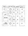
- FIG. 4is a diagram illustrating an example of an operation mode of the breaking device.
- FIG. 5is a block diagram schematically showing the configuration of the blocking device.
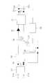
- FIG. 1is a block diagram schematically showing the configuration of the photovoltaic power generation system 1 according to one aspect of the present invention.
- the photovoltaic power generation system 1includes a string 2, an inverter 3, and a plurality of breaking devices 4a to 4c.
- the string 2includes a plurality of solar cell modules 5 connected in series with each other.
- the string 2 in this embodimentis composed of 16 solar cell modules 5 including the solar cell modules 5a to 5h.
- the string 2includes a plurality of solar cell module groups including each of the plurality of solar cell modules 5.
- the string 2includes a plurality of solar cell module groups in which the plurality of solar cell modules 5 are divided into three or more groups.
- the string 2 in the present embodimentincludes solar cell module groups 5A to 5D in which a plurality of solar cell modules 5 are divided into four groups.
- the solar cell module groups 5A to 5Dwill be described as groups 5A to 5D.
- the solar cell module 5ais an example of the first solar cell module.
- the solar cell module 5bis an example of the second solar cell module.
- the solar cell module 5cis an example of a third solar cell module.
- the solar cell module 5dis an example of the fourth solar cell module.
- the solar cell module 5eis an example of the fifth solar cell module.
- Group 5Ais connected to group B.
- Group 5Aincludes at least a solar cell module 5a and a solar cell module 5b among the plurality of solar cell modules 5.
- the solar cell module 5ais connected to the group 5B.
- the solar cell module 5bis connected to the solar cell module 5a.
- the group 5A in the present embodimentis composed of four solar cell modules 5 including the solar cell modules 5a and 5b.
- Group Bis located between Group A and Group C and is connected to Group A and Group C.
- Group 5Bincludes at least a solar cell module 5c and a solar cell module 5d among the plurality of solar cell modules 5.
- the solar cell module 5cis connected to the solar cell module 5a.
- the solar cell module 5dis connected to the group 5C.
- Group 5B in the present embodimentincludes four solar cell modules including the solar cell modules 5c and 5d, two solar cell modules 5 arranged between the solar cell modules 5c and the solar cell module 5d, and four solar cell modules. It is composed of 5.
- Group Cis located between Group B and Group D and is connected to Group B and Group D.
- Group 5Cincludes at least a solar cell module 5e and a solar cell module 5f among the plurality of solar cell modules 5.
- the solar cell module 5eis connected to the solar cell module 5d.
- the solar cell module 5fis connected to the group 5D.
- Group 5C in the present embodimentincludes four solar cell modules including a solar cell module 5e, 5f, two solar cell modules 5 arranged between the solar cell module 5e and the solar cell module 5f, and four solar cell modules. It is composed of 5.
- Group Dis connected to Group C.
- Group Dincludes a solar cell module 5g and a solar cell module 5h among the plurality of solar cell modules 5.
- the solar cell module 5gis connected to the solar cell module 5f.
- the solar cell module 5his connected to the solar cell module 5g.
- Group 5D in this embodimentis composed of four solar cell modules 5 including solar cell modules 5g and 5h.
- each of the groups 5A to 5Dincludes four solar cell modules 5 connected in series.
- the photovoltaic power generation system 1may include a solar cell array in which a plurality of strings 2 are connected in parallel.
- the solar cell module 5receives sunlight to generate electric power, and outputs the generated electric power to the inverter 3.
- the open circuit voltage of the solar cell module 5is, for example, 50V.
- the inverter 3is connected to the string 2 via the power line 6.
- the inverter 3converts the DC power output from the solar cell module 5a into AC power.
- the inverter 3is connected to the power system 7 and supplies AC power to the commercial power system and the load device.
- the inverter 3includes a DC / DC converter 3a, a DC / AC inverter 3b, and a control unit 3c.
- the DC / DC converter 3aconverts the voltage of the electric power output from the solar cell module 5 into a predetermined voltage and inputs it to the DC / AC inverter 3b.
- the DC / AC inverter 3bconverts the DC power output from the solar cell module 5 into AC power via the DC / DC converter 3a.
- the control unit 3cincludes a CPU, a memory, and the like, and controls the DC / DC converter 3a and the DC / AC inverter 3b. Further, the control unit 3c outputs a control signal to the cutoff devices 4a to 4c by power line communication.
- the breaking devices 4a to 4care arranged at a plurality of intermediate points of the string 2 and cut off the voltage output from the solar cell module 5 in response to the control signal from the inverter 3.
- the intermediate pointhere means an electric circuit to which the solar cell modules 5 are connected to each other.
- the breaking devices 4a to 4care externally attached to the solar cell module 5.
- Bypass diodesare not provided in the breaking devices 4a to 4c. Therefore, when the voltage output from the solar cell module 5a is cut off by the cutoff devices 4a to 4c, the voltage input to the inverter 3 is cut off.
- the cutoff device 4acuts off the connection between the solar cell module 5a and the solar cell module 5c by cutting off the voltage output from the solar cell module 5a. As a result, the connection between the group A and the group B is cut off.
- the blocking device 4ais connected to an electric circuit 8a that connects the solar cell module 5a and the solar cell module 5b, and an electric circuit 8b that connects the solar cell module 5a and the solar cell module 5c.
- the cutoff device 4ais driven by the electric power generated by the solar cell module 5a.
- the cutoff device 4bcuts off the connection between the solar cell module 5d and the solar cell module 5e by cutting off the voltage output from the solar cell module 5d. As a result, the connection between the group B and the group C is cut off.
- the blocking device 4bincludes an electric circuit 8c that connects the solar cell module 5 and the solar cell module 5d connected to the solar cell module 5d in group B, and an electric path 8d that connects the solar cell module 5d and the solar cell module 5e. Is connected to.
- the cutoff device 4bis driven by the electric power generated by the solar cell module 5d.
- the cutoff device 4ccuts off the connection between the solar cell module 5f and the solar cell module 5g by cutting off the voltage output from the solar cell module 5f. As a result, the connection between the group C and the group D is cut off.
- the cutoff device 4chas an electric path 8e for connecting the solar cell module 5 and the solar cell module 5f connected to the solar cell module 5f in group C, and an electric path 8f for connecting the solar cell module 5f and the solar cell module 5g. It is connected.
- the cutoff device 4cis driven by the electric power generated by the solar cell module 5f.
- FIG. 2is a block diagram schematically showing the configuration of the blocking device 4a.
- the breaking device 4aincludes a regulator 11, a signal receiving unit 12, a relay control unit 13, a relay 14a, and a bypass circuit 15.
- the regulator 11uses the electric power generated by the solar cell module 5a as a power source to generate a drive power source for driving the cutoff device 4a, and supplies a stable drive power source to the cutoff device 4a.
- the electric power generated by the single solar cell module 5solar cell module 5a
- the drive voltage range of the regulator 11can be suppressed to a small size, so that the manufacturing cost of the breaking device 4a can be suppressed.
- FIG. 3is a circuit diagram schematically showing the configuration of the regulator 11.
- the configuration of the regulator 11is a well-known configuration, and is an input terminal 21a, 21b, an output terminal 22a, 22b, a line filter 23, a capacitor 24, 25, a booster circuit 26, a switching element 27, a control circuit 28, a transformer 29, and a diode 30. , DC / DC converter 31, feedback circuit 32 and the like.
- the signal receiving unit 12receives the control signal from the control unit 3c of the inverter 3 and outputs the received control signal to the relay control unit 13. Specifically, the signal receiving unit 12 receives the control signal from the control unit 3c of the inverter 3 via the signal detecting unit 16 that detects the control signal from the control unit 3c of the inverter 3.
- the relay control unit 13controls the current value flowing through the coil of the relay 14a based on the signal output from the signal reception unit 12, and controls the opening and closing of the contacts of the relay 14a.
- the relay 14ais arranged in the electric circuit 8b.
- the relay 14ais, for example, a mechanical relay in which contacts are connected in series, and can open and close a high-voltage direct current.
- the contacts of the relay 14aare always in the open state. Therefore, when the breaking device 4a is not driven, the connection between the group 5A and the group B is cut off.
- the bypass circuit 15is a circuit for allowing the signal receiving unit 12 to receive the control signal from the control unit 3c when the breaking device 4a is in the breaking state.
- the signal receiving unit 12can receive the control signal from the control unit 3c via the bypass circuit 15.
- the configuration of the blocking device 4b and the blocking device 4cis the same as that of the blocking device 4a except that the connected electric circuit is different from the blocking device 4a, and thus the description thereof will be omitted.
- the operation modes of the shutoff devices 4a to 4cinclude three operation modes of a start mode, an active mode, and a safety mode.
- the safety modeincludes a normal shutoff mode and an emergency safety shutoff mode. Therefore, the shutoff devices 4a to 4c operate in four operation modes: a start mode, an active mode, a normal shutoff mode, and an emergency safety shutoff mode.
- the start modeis a mode when sunlight begins to hit the solar cell module 5.
- the solar cell module 5receives sunlight to generate electric power.
- the shutoff device 4ais driven by the drive power source generated by the regulator 11 from the electric power generated by the solar cell module 5a.
- the relay control unit 13receives the control signal from the control unit 3c of the inverter 3 via the signal reception unit 12, the relay control unit 13 connects the contacts of the relay 14a as shown in FIG. Control to close.
- the cutoff device 4bis driven by the electric power generated by the solar cell module 5d, and closes the contacts of the relay 14b arranged in the electric circuit 8d in response to the control signal from the control unit 3c of the inverter 3.
- the cutoff device 4cis driven by the electric power generated by the solar cell module 5f, and closes the contacts of the relay 14c arranged in the electric circuit 8f in response to the control signal from the control unit 3c of the inverter 3.
- the groups 5A to 5Dare connected via the breaking devices 4a to 4c, and the electric power generated by each solar cell module 5 including the solar cell modules 5a to 5h is output to the inverter 3.
- the active modeis a state in which the solar cell module 5 receives sunlight during the day to generate electricity, which is substantially the same as the start mode. Therefore, in the active mode, the groups 5A to 5D are in a state of being connected via the breaking devices 4a to 4c, and the electric power generated by the solar cell module 5 is output to the inverter 3.
- the normal cutoff modeis a mode when the solar cell module 5 is not receiving sunlight at night or due to the influence of weather such as rain. Therefore, in the normal cutoff mode, power is not generated by the solar cell module 5, and drive power is not supplied from the solar cell module 5a to the cutoff device 4a. Similarly, no drive power is supplied to the cutoff device 4b and the cutoff device 4c. Therefore, in the normal cutoff mode, the connection between the groups 5A to 5D is cut off. In this embodiment, power is supplied to the inverter 3 from the AC power supply, and the control signal is always output from the control unit 3c of the inverter 3 except in the emergency safety cutoff mode.
- the relay 14aoperates on / off according to the power supplied from the solar cell module 5a. ..
- the emergency safety cutoff modeis a mode in which the connection between the groups 5A to 5D is cut off during the start mode or the active mode to stop the output of electric power from the solar cell module 5 to the inverter 3.
- the operation switch 35when the operation switch 35 is connected to the inverter 3 and the operation switch 35 is operated while the shutoff devices 4a to 4c are in the start mode or the active mode, the shutoff is performed.
- the operation mode of the devices 4a to 4cis switched to the emergency safety cutoff mode.
- the control unit 3cstops the output of the control signal.
- the signal detection unit 16detects that the control signal is stopped for a certain period of time, the contacts of the relays 14a to 14c are opened as shown in FIG. 1 via the signal reception unit 12 and the relay control unit 13. As a result, the voltages output from all the solar cell modules 5 are cut off, and the connections between the groups 5A to 5D are cut off.
- the blocking devices 4a to 4cwhen the operation mode of the blocking devices 4a to 4c is the emergency safety shutoff mode, the blocking devices 4a to 4c can shut off the plurality of solar cell modules 5. Therefore, the installation cost of the breaking device can be reduced as compared with the case where the breaking device is installed for each solar cell module 5. Further, it is possible to provide a solar power generation system having higher safety than the case where the solar cell module 5a and the inverter 3 are cut off by the string 2 unit. Specifically, when the open circuit voltage of the solar cell module 5 is 50 V, the open circuit voltage for each group 5A to 5D in the present embodiment is 200 V, and the open circuit voltage of the string 2 is 800 V.
- the solar cell module 5continues to generate power after the connection between the groups 5A to 5D is cut off, the voltage of each group 5A to 5D becomes 200V at the maximum, and the connection with the inverter 3 is cut off in units of strings 2. It will be safer than if you did.
- the photovoltaic power generation system 1it is possible to secure communication with the drive power supply of the cutoff devices 4a to 4c and the inverter 3 by using the power line 6.
- the breaking devices 4a to 4care installed in the existing photovoltaic power generation system, additional wiring for connecting the inverter 3 and the breaking devices 4a to 4c is not required. Therefore, it is possible to reduce the installation cost when installing the shutoff devices 4a to 4c in the existing photovoltaic power generation system.
- the cutoff devices 4a to 4cneed only be connected to one solar cell module 5, the wiring is shorter and simpler than the case where the cutoff devices 4a to 4c are connected to a plurality of solar cell modules 5. As a result, for example, it is possible to reduce the installation cost when installing the shutoff devices 4a to 4c in the existing photovoltaic power generation system, and to perform the construction with high flexibility.
- bypass diodeis omitted in the breaking devices 4a to 4c, the manufacturing cost of the breaking devices 4a to 4c can be suppressed.
- the operation mode of the cutoff devices 4a to 4ccan be switched from the emergency safety cutoff mode to the start mode according to the control signal of the control unit 3c.
- each of the groups 5A to 5Dincludes four solar cell modules 5, but the number of solar cell modules 5 is not limited to the above embodiment. Further, each of the groups 5A to 5D does not necessarily include the same number of solar cell modules 5. For example, group 5A may include four solar cell modules 5 and group 5B may include five solar cell modules 5.
- the string 2includes four groups 5A to 5D, but the number of groups is not limited to the above embodiment.
- string 2may include five groups.
- the arrangement and the number of the blocking devices 4a to 4care not limited to the above-described embodiment.
- switching to the emergency safety shutoff modeis performed by operating the operation switch 35, but switching from the start mode or the active mode to the emergency safety shutoff mode is not limited to the above embodiment.
- the photovoltaic power generation system 1may be provided with a sensor that detects the output state of the solar cell module 5.
- the control unit 3c of the inverter 3stops the control signal when an abnormality is detected from the output state of the solar cell module 5 detected by the sensor, and the cutoff devices 4a to 4c cut off the connection between the groups 5A to 5D. You may.
- a fire alarm or fire alarmis connected to the inverter 3, and when the inverter 3 receives a signal from the fire alarm or fire alarm, the control signal from the control unit 3c is stopped to stop the shutoff device 4a.
- the connection between groups 5A to 5Dmay be blocked by ⁇ 4c.
- a photovoltaic power generation systemin a photovoltaic power generation system, it is possible to provide a photovoltaic power generation system that can both reduce the installation cost of a shutoff device and improve safety.
Landscapes
- Photovoltaic Devices (AREA)
- Supply And Distribution Of Alternating Current (AREA)
Abstract
Description
Translated fromJapanese本発明は、太陽光発電システムに関する。The present invention relates to a photovoltaic power generation system.
米国では、火災時等の緊急時に消防士を感電等から保護することを目的として、太陽光発電システムに対して、緊急時に太陽光発電システムによる発電を即座に停止するいわゆるラピッドシャットダウン機能の導入がNEC(米国電気工事規定)によって義務付けられている。例えば、特許文献1では、インバータの動作状態に応じて、太陽電池モジュールからインバータへの電力の出力を停止させる太陽光発電システムが開示されている。In the United States, for the purpose of protecting firefighters from electric shock in an emergency such as a fire, a so-called rapid shutdown function has been introduced to the photovoltaic power generation system to immediately stop the power generation by the photovoltaic power generation system in an emergency. Mandated by NEC (US Electrical Construction Regulations). For example,
太陽光発電システムにおいて、火災時等における消防士のさらなる安全性の向上を図るには、例えば、ラピッドシャットダウン機能を備える遮断装置を太陽電池モジュール毎に設置することが好ましい。しかしながら、太陽電池モジュール毎に遮断装置を設置した場合、遮断装置の設置コストが高くなる。In a photovoltaic power generation system, in order to further improve the safety of firefighters in the event of a fire, for example, it is preferable to install a shutoff device having a rapid shutdown function for each solar cell module. However, if a breaking device is installed for each solar cell module, the installation cost of the breaking device becomes high.
本発明の課題は、太陽光発電システムにおいて、遮断装置の設置コストの低減、及び安全性の向上を両立できる太陽光発電システムを提供することにある。An object of the present invention is to provide a photovoltaic power generation system capable of reducing the installation cost of a shutoff device and improving safety in the photovoltaic power generation system.
本発明の一態様に係る太陽光発電システムは、ストリングと、インバータと、遮断装置と、を備える。ストリングは、複数の太陽電池モジュールが直列に接続されている。インバータは、ストリングに接続され、太陽電池モジュールから出力される直流電力を交流電力に変換する。遮断装置は、ストリングの複数の中間点に配置され、インバータからの制御信号に応じて太陽電池モジュールから出力される電圧を遮断する。The photovoltaic power generation system according to one aspect of the present invention includes a string, an inverter, and a breaking device. In the string, a plurality of solar cell modules are connected in series. The inverter is connected to the string and converts the DC power output from the solar cell module into AC power. The breaking device is arranged at a plurality of intermediate points of the string and cuts off the voltage output from the solar cell module in response to the control signal from the inverter.
この太陽光発電システムでは、遮断装置がストリングの複数の中間点に配置されているので、インバータからの制御信号に応じて太陽電池モジュールから出力される電圧を遮断したときに、1個の遮断装置で複数の太陽電池モジュールをまとめて遮断することができる。これにより、太陽電池モジュール毎に遮断装置を設置する場合に比べて、遮断装置の設置コストの低減を図ることができる。また、ストリング単位で太陽電池モジュールとインバータとを遮断する場合に比べて、より安全性の高い太陽光発電システムを提供することができる。In this photovoltaic power generation system, since the breaking devices are arranged at a plurality of intermediate points of the string, one breaking device is used when the voltage output from the solar cell module is cut in response to the control signal from the inverter. Can shut down multiple solar cell modules at once. As a result, the installation cost of the breaking device can be reduced as compared with the case where the breaking device is installed for each solar cell module. Further, it is possible to provide a solar power generation system having higher safety than the case where the solar cell module and the inverter are shut off in string units.
ストリングは、複数の太陽電池モジュールをそれぞれ含む複数の太陽電池モジュールグループを含んでもよい。複数の前記太陽電池モジュールグループは、第1グループ、第1グループに接続される第2グループ、及び第2グループに接続される第3グループを少なくとも含んでもよい。第1グループは、複数の太陽電池モジュールのうち、第2グループに接続される第1太陽電池モジュールと、第1太陽電池モジュールに接続される第2太陽電池モジュールと、を少なくとも含んでもよい。第2グループは、複数の太陽電池モジュールのうち、第1太陽電池モジュールに接続される第3太陽電池モジュールと、第3グループに接続される第4太陽電池モジュールと、を少なくとも含んでもよい。第3グループは、複数の太陽電池モジュールのうち、第4太陽電池モジュールに接続される第5太陽電池モジュールを少なくとも含んでもよい。遮断装置は、第1太陽電池モジュールにから出力される電圧を遮断することによって第1太陽電池モジュールと第3太陽電池モジュールとの接続を遮断する第1遮断装置と、第4太陽電池モジュールから出力される電圧を遮断することによって第4太陽電池モジュールと第5太陽電池モジュールとの接続を遮断する第2遮断装置と、を含んでもよい。この場合においても、前述した効果と同様の効果を得ることができる。The string may include a plurality of solar cell module groups each including a plurality of solar cell modules. The plurality of solar cell module groups may include at least a first group, a second group connected to the first group, and a third group connected to the second group. The first group may include at least a first solar cell module connected to the second group and a second solar cell module connected to the first solar cell module among the plurality of solar cell modules. The second group may include at least a third solar cell module connected to the first solar cell module and a fourth solar cell module connected to the third group among the plurality of solar cell modules. The third group may include at least a fifth solar cell module connected to the fourth solar cell module among the plurality of solar cell modules. The breaking device outputs from the first breaking device and the fourth solar cell module that cut off the connection between the first solar cell module and the third solar cell module by cutting off the voltage output from the first solar cell module. A second cutoff device that cuts off the connection between the fourth solar cell module and the fifth solar cell module by cutting off the voltage to be generated may be included. Also in this case, the same effect as the above-mentioned effect can be obtained.
第1遮断装置は、第1太陽電池モジュールと第2太陽電池モジュールを接続する第1電路と、第1太陽電池モジュールと第3太陽電池モジュールとを接続する第2電路とに接続されてもよい。第2遮断装置は、第2グループにおいて第4太陽電池モジュールに接続される太陽電池モジュールと第4太陽電池モジュールを接続する第3電路と、第4太陽電池モジュールと第5太陽電池モジュールとを接続する第4電路とに接続されてもよい。この場合は、遮断装置と太陽電池モジュールとを接続する配線が短くかつ簡易になる。The first blocking device may be connected to a first electric circuit connecting the first solar cell module and the second solar cell module, and a second electric circuit connecting the first solar cell module and the third solar cell module. .. The second blocking device connects the third electric circuit connecting the solar cell module connected to the fourth solar cell module and the fourth solar cell module in the second group, and the fourth solar cell module and the fifth solar cell module. It may be connected to the fourth electric circuit. In this case, the wiring connecting the breaking device and the solar cell module becomes short and simple.
第1遮断装置は、第1太陽電池モジュールで発電される電力によって駆動されてもよい。第2遮断装置は、第4太陽電池モジュールで発電される電力によって駆動されてもよい。この場合は、例えば、既存の太陽光発電システムに遮断装置を設置するときにおいて、インバータと遮断装置とを接続して遮断装置の電源を確保する必要がない。これにより、インバータと遮断装置とを接続する追加配線を省略することができるので、遮断装置の設置コストの低減を図ることができる。また、遮断装置の駆動電圧範囲を小さく抑えることができるので、遮断装置の製造コストを抑えることができる。The first shutoff device may be driven by the electric power generated by the first solar cell module. The second cutoff device may be driven by the electric power generated by the fourth solar cell module. In this case, for example, when installing a breaking device in an existing photovoltaic power generation system, it is not necessary to connect the inverter and the breaking device to secure the power supply for the breaking device. As a result, the additional wiring for connecting the inverter and the breaking device can be omitted, so that the installation cost of the breaking device can be reduced. Further, since the drive voltage range of the breaking device can be suppressed to a small size, the manufacturing cost of the breaking device can be suppressed.
インバータは、電力線通信によって遮断装置に制御信号を出力してもよい。この場合は、既存の太陽光発電システムに遮断装置を設置するときに、インバータと遮断装置との通信を確保するための追加配線を省略することができるので、遮断装置の設置コストの低減を図ることができる。The inverter may output a control signal to the cutoff device by power line communication. In this case, when installing the breaking device in the existing photovoltaic power generation system, the additional wiring for ensuring the communication between the inverter and the breaking device can be omitted, so that the installation cost of the breaking device can be reduced. be able to.
遮断装置は、太陽電池モジュールに外付けされてもよい。この場合は、既存の太陽光発電システムへの遮断装置の設置が容易にできる。The blocking device may be externally attached to the solar cell module. In this case, the shutoff device can be easily installed in the existing photovoltaic power generation system.
遮断装置は、インバータからの信号を受信する信号受信部と、太陽電池モジュールグループ間の接続が遮断された状態において信号受信部がインバータからの信号を受信するためのバイパス回路と、を含んでもよい。この場合は、太陽電池モジュールから出力される電圧が遮断された状態にあるときに、インバータからの信号に応じて、遮断状態を解除することができる。The cutoff device may include a signal receiver for receiving a signal from the inverter and a bypass circuit for the signal receiver to receive the signal from the inverter when the connection between the solar cell module groups is cut off. .. In this case, when the voltage output from the solar cell module is in the cutoff state, the cutoff state can be released in response to the signal from the inverter.
本発明によれば、太陽光発電システムにおいて、遮断装置の設置コストの低減、及び安全性の向上を両立できる太陽光発電システムを提供することができる。According to the present invention, in a photovoltaic power generation system, it is possible to provide a photovoltaic power generation system that can both reduce the installation cost of a shutoff device and improve safety.
図1は、本発明の一態様に係る太陽光発電システム1の構成を模式的に示すブロック図である。太陽光発電システム1は、ストリング2と、インバータ3と、複数の遮断装置4a~4cと、を備える。FIG. 1 is a block diagram schematically showing the configuration of the photovoltaic
ストリング2は、互いに直列に接続された複数の太陽電池モジュール5を含む。本実施形態におけるストリング2は、太陽電池モジュール5a~5hを含めた16個の太陽電池モジュール5で構成されている。ストリング2は、複数の太陽電池モジュール5をそれぞれ含む複数の太陽電池モジュールグループを含む。詳細には、ストリング2は、複数の太陽電池モジュール5を3以上のグループに分割した複数の太陽電池モジュールグループを含む。本実施形態におけるストリング2は、複数の太陽電池モジュール5を4個のグループに分割した太陽電池モジュールグループ5A~5Dを含む。なお、以下からの説明を分かり易くするために、太陽電池モジュールグループ5A~5Dをグループ5A~5Dとして説明する。The
なお、太陽電池モジュール5aは、第1太陽電池モジュールの一例である。太陽電池モジュール5bは、第2太陽電池モジュールの一例である。太陽電池モジュール5cは、第3太陽電池モジュールの一例である。太陽電池モジュール5dは、第4太陽電池モジュールの一例である。太陽電池モジュール5eは、第5太陽電池モジュールの一例である。The
グループ5Aは、グループBに接続される。グループ5Aは、複数の太陽電池モジュール5のうち、太陽電池モジュール5aと、太陽電池モジュール5bと、を少なくとも含む。太陽電池モジュール5aは、グループ5Bに接続される。太陽電池モジュール5bは、太陽電池モジュール5aに接続される。図1に示すように、本実施形態におけるグループ5Aは、太陽電池モジュール5a,5bを含めた4個の太陽電池モジュール5で構成されている。
グループBは、グループAとグループCの間に位置し、グループAとグループCとに接続される。グループ5Bは、複数の太陽電池モジュール5のうち、太陽電池モジュール5cと、太陽電池モジュール5dと、を少なくとも含む。太陽電池モジュール5cは、太陽電池モジュール5aに接続される。太陽電池モジュール5dは、グループ5Cに接続される。本実施形態におけるグループ5Bは、太陽電池モジュール5c,5dと、太陽電池モジュール5cと太陽電池モジュール5dとの間に配置された2個の太陽電池モジュール5と、を含めた4個の太陽電池モジュール5で構成されている。Group B is located between Group A and Group C and is connected to Group A and Group C.
グループCは、グループBとグループDの間に位置し、グループBとグループDとに接続される。グループ5Cは、複数の太陽電池モジュール5のうち、太陽電池モジュール5eと、太陽電池モジュール5fと、を少なくとも含む。太陽電池モジュール5eは、太陽電池モジュール5dに接続される。太陽電池モジュール5fは、グループ5Dに接続される。本実施形態におけるグループ5Cは、太陽電池モジュール5e,5fと、太陽電池モジュール5eと太陽電池モジュール5fとの間に配置された2個の太陽電池モジュール5と、を含めた4個の太陽電池モジュール5で構成されている。Group C is located between Group B and Group D and is connected to Group B and
グループDは、グループCに接続される。グループDは、複数の前記太陽電池モジュール5のうち、太陽電池モジュール5gと、太陽電池モジュール5hと、を含む。太陽電池モジュール5gは、太陽電池モジュール5fに接続される。太陽電池モジュール5hは、太陽電池モジュール5gに接続される。本実施形態におけるグループ5Dは、太陽電池モジュール5g,5hを含めた4個の太陽電池モジュール5で構成されている。Group D is connected to Group C. Group D includes a
すなわち、本実施形態では、グループ5A~5Dのそれぞれが直列に接続された4個の太陽電池モジュール5を含む。なお、太陽光発電システム1は、ストリング2が並列に複数連結された太陽電池アレイを含んでもよい。That is, in the present embodiment, each of the
太陽電池モジュール5は、太陽光を受けて電力を発電し、発電した電力をインバータ3に出力する。太陽電池モジュール5の開放電圧は、例えば、50Vである。インバータ3は、電力線6を介してストリング2に接続される。インバータ3は、太陽電池モジュール5aから出力される直流電力を交流電力に変換する。インバータ3は、電力系統7に接続されており、交流電力を商用電力系統や負荷装置に供給する。The
詳細には、インバータ3は、DC/DCコンバータ3aと、DC/ACインバータ3bと、制御部3cと、を含む。DC/DCコンバータ3aは、太陽電池モジュール5から出力される電力の電圧を所定の電圧に変換して、DC/ACインバータ3bに入力する。DC/ACインバータ3bは、DC/DCコンバータ3aを介して、太陽電池モジュール5から出力される直流電力を交流電力に変換する。制御部3cは、CPUやメモリ等を含み、DC/DCコンバータ3a及びDC/ACインバータ3bを制御する。また、制御部3cは、電力線通信によって遮断装置4a~4cに制御信号を出力する。Specifically, the
遮断装置4a~4cは、ストリング2の複数の中間点に配置され、インバータ3からの制御信号に応じて太陽電池モジュール5から出力される電圧を遮断する。ここでの中間点とは、太陽電池モジュール5同士が接続されている電路を意味する。遮断装置4a~4cは、太陽電池モジュール5に外付けされている。The
遮断装置4a~4cには、バイパスダイオードが設けられていない。このため、遮断装置4a~4cによって太陽電池モジュール5aから出力される電圧が遮断されると、インバータ3に入力される電圧が遮断される。Bypass diodes are not provided in the
遮断装置4aは、太陽電池モジュール5aから出力される電圧を遮断することによって太陽電池モジュール5aと太陽電池モジュール5cとの接続を遮断する。これにより、グループAとグループBとの接続が遮断される。遮断装置4aは、太陽電池モジュール5aと太陽電池モジュール5bを接続する電路8aと、太陽電池モジュール5aと太陽電池モジュール5cとを接続する電路8bとに接続されている。遮断装置4aは、太陽電池モジュール5aで発電される電力によって駆動される。The
遮断装置4bは、太陽電池モジュール5dから出力される電圧を遮断することによって太陽電池モジュール5dと太陽電池モジュール5eとの接続を遮断する。これにより、グループBとグループCとの接続が遮断される。遮断装置4bは、グループBにおいて太陽電池太陽電池モジュール5dに接続される太陽電池モジュール5と太陽電池モジュール5dとを接続する電路8cと、太陽電池モジュール5dと太陽電池モジュール5eとを接続する電路8dとに接続されている。遮断装置4bは、太陽電池モジュール5dで発電される電力によって駆動される。The
遮断装置4cは、太陽電池モジュール5fから出力される電圧を遮断することによって太陽電池モジュール5fと太陽電池モジュール5gとの接続を遮断する。これにより、グループCとグループDとの接続が遮断される。遮断装置4cは、グループCにおいて太陽電池モジュール5fに接続される太陽電池モジュール5と太陽電池モジュール5fとを接続する電路8eと、太陽電池モジュール5fと太陽電池モジュール5gとを接続する電路8fとに接続されている。遮断装置4cは、太陽電池モジュール5fで発電される電力によって駆動される。The
図2は、遮断装置4aの構成を模式的に示すブロック図である。遮断装置4aは、レギュレータ11と、信号受信部12と、リレー制御部13と、リレー14aと、バイパス回路15と、を含む。FIG. 2 is a block diagram schematically showing the configuration of the
レギュレータ11は、太陽電池モジュール5aで発電された電力を電源として遮断装置4aを駆動させる駆動電源を生成し、遮断装置4aに安定した駆動電源を供給する。ここでは、単一の太陽電池モジュール5(太陽電池モジュール5a)で発電された電力のみを利用して遮断装置4aの駆動電源を生成する。これにより、レギュレータ11の駆動電圧範囲を小さく抑えることができるので、遮断装置4aの製造コストを抑えることができる。The
図3は、レギュレータ11の構成を模式的に示す回路図である。レギュレータ11の構成は、周知の構成であり、入力端子21a,21b、出力端子22a,22b、ラインフィルタ23、コンデンサ24,25、昇圧回路26、スイッチング素子27、制御回路28、トランス29、ダイオード30、DC/DCコンバータ31、フィードバック回路32等を含む。FIG. 3 is a circuit diagram schematically showing the configuration of the
信号受信部12は、インバータ3の制御部3cからの制御信号を受信して、受信した制御信号をリレー制御部13に出力する。詳細には、インバータ3の制御部3cからの制御信号を検出する信号検出部16を介して、信号受信部12はインバータ3の制御部3cからの制御信号を受信する。The
リレー制御部13は、信号受信部12から出力された信号に基づいて、リレー14aのコイルに流れる電流値を制御して、リレー14aの接点を開閉制御する。リレー14aは、電路8bに配置されている。The
リレー14aは、例えば、接点が直列に接続されたメカニカルリレーであり、高電圧の直流電流を開閉可能である。遮断装置4aに駆動電源が供給されていないとき、リレー14aの接点は、常に開いた状態にある。したがって、遮断装置4aが駆動していないときは、グループ5AとグループBの接続が遮断された状態にある。The
バイパス回路15は、遮断装置4aが遮断状態のときに制御部3cからの制御信号を信号受信部12が受信できるようにするための回路である。遮断装置4aによって太陽電池モジュール5aから出力される電圧が遮断された状態のとき、信号受信部12は、バイパス回路15を介して、制御部3cからの制御信号を受信することができる。The
遮断装置4b及び遮断装置4cの構成は、接続される電路が遮断装置4aと異なる点を除いて遮断装置4aと同様の構成であるため説明を省略する。The configuration of the
次に、図4を参照して遮断装置4a~4cの動作モードの一例について説明する。遮断装置4a~4cの動作モードは、スタートモード、アクティブモード、安全モードの3つの動作モードを含む。安全モードは、通常遮断モードと、緊急安全遮断モードと、を含む。したがって、遮断装置4a~4cは、スタートモード、アクティブモード、通常遮断モード、及び緊急安全遮断モードの4つの動作モードで動作する。Next, an example of the operation modes of the
スタートモードとは、太陽電池モジュール5に太陽光が当たり始めたときのモードである。このとき、太陽電池モジュール5は、太陽光を受けて電力を発電する。そして、太陽電池モジュール5aで発電された電力からレギュレータ11が生成した駆動電源によって遮断装置4aが駆動される。遮断装置4aが駆動されてリレー制御部13が信号受信部12を介してインバータ3の制御部3cからの制御信号を受信すると、図5に示すように、リレー制御部13はリレー14aの接点を閉じるように制御する。同様に、遮断装置4bは、太陽電池モジュール5dで発電された電力によって駆動され、インバータ3の制御部3cからの制御信号に応じて、電路8dに配置されたリレー14bの接点を閉じる。同様に、遮断装置4cは、太陽電池モジュール5fで発電された電力によって駆動され、インバータ3の制御部3cからの制御信号に応じて、電路8fに配置されたリレー14cの接点を閉じる。これにより、グループ5A~5Dが遮断装置4a~4cを介して接続され、太陽電池モジュール5a~5hを含む各太陽電池モジュール5で発電された電力がインバータ3に出力される。The start mode is a mode when sunlight begins to hit the
アクティブモードは、太陽電池モジュール5が日中に太陽光を受けて発電している状態であり、実質的にスタートモードと同じである。したがって、アクティブモードでは、グループ5A~5Dが遮断装置4a~4cを介して接続された状態にあり、太陽電池モジュール5が発電した電力がインバータ3に出力される。The active mode is a state in which the
通常遮断モードは、夜間、或いは雨等の天候の影響で、太陽電池モジュール5が太陽光を受けていないときのモードである。したがって、通常遮断モードでは、太陽電池モジュール5によって電力が発電されておらず、太陽電池モジュール5aから遮断装置4aに駆動電源が供給されていない。同様に、遮断装置4b及び遮断装置4cにも駆動電源が供給されていない。このため、通常遮断モードでは、グループ5A~5D間の接続が遮断されている。なお、本実施形態では、インバータ3にAC電源から電力が供給されており、緊急安全遮断モード時を除いて、インバータ3の制御部3cから制御信号が常に出力されている。The normal cutoff mode is a mode when the
通常遮断モードにおいて、天候の不安定等の理由により、例えば太陽電池モジュール5aの発電が不安定な状態のときは、太陽電池モジュール5aから供給される電力に応じてリレー14aがオン/オフ動作する。In the normal cutoff mode, for example, when the power generation of the
緊急安全遮断モードは、スタートモード、或いはアクティブモード中に、グループ5A~5D相互間の接続を遮断して、太陽電池モジュール5からインバータ3への電力の出力を停止させるモードである。本実施形態では、図1に示すように、操作スイッチ35がインバータ3に接続されており、遮断装置4a~4cがスタートモード、或いはアクティブモード中のときに操作スイッチ35が操作されると、遮断装置4a~4cの動作モードが緊急安全遮断モードに切り替わる。The emergency safety cutoff mode is a mode in which the connection between the
詳細には、操作スイッチ35が操作されると、制御部3cは、制御信号の出力を停止する。信号検出部16が制御信号の一定周期停止を検出すると、信号受信部12及びリレー制御部13を介して、図1に示すようにリレー14a~14cの接点が開かれる。これにより、全ての太陽電池モジュール5から出力される電圧が遮断されるとともに、グループ5A~5D間の接続が遮断される。Specifically, when the
上記構成の太陽光発電システム1では、遮断装置4a~4cの動作モードが緊急安全遮断モードのときに、遮断装置4a~4cによって複数の太陽電池モジュール5を遮断することができる。このため、太陽電池モジュール5毎に遮断装置を設置する場合に比べて、遮断装置の設置コストの低減を図ることができる。また、ストリング2単位で太陽電池モジュール5aとインバータ3とを遮断する場合に比べて、より安全性の高い太陽光発電システムを提供することができる。具体的には、太陽電池モジュール5の開放電圧が50Vの場合、本実施形態におけるグループ5A~5D毎の開放電圧は200Vであり、ストリング2の開放電圧は800Vとなる。したがって、グループ5A~5D間の接続が遮断された後、太陽電池モジュール5が発電を継続した場合、各グループ5A~5Dの電圧は最大で200Vとなり、ストリング2単位でインバータ3との接続を遮断した場合に比べてより安全性が高くなる。In the photovoltaic
また、太陽光発電システム1では、電力線6を利用して遮断装置4a~4cの駆動電源及びインバータ3との通信を確保することができる。これにより、例えば、既存の太陽光発電システムに遮断装置4a~4cを設置するときに、インバータ3と遮断装置4a~4cとを接続する追加配線を必要としない。このため、既存の太陽光発電システムに遮断装置4a~4cを設置する際の設置コストの低減を図ることができる。Further, in the photovoltaic
また、遮断装置4a~4cは、1個の太陽電池モジュール5に接続すればよいので、遮断装置4a~4cを複数の太陽電池モジュール5に接続する場合に比べて配線が短くかつ簡易になる。これにより、例えば、既存の太陽光発電システムに遮断装置4a~4cを設置する際の設置コストの低減や、柔軟性の高い施工が可能になる。Further, since the
また、遮断装置4a~4cでは、バイパスダイオードが省略されるので、遮断装置4a~4cの製造コストを抑えることができる。Further, since the bypass diode is omitted in the
また、遮断装置4a~4cにバイパス回路15を設けることで、遮断装置4a~4cの動作モードを、制御部3cの制御信号に応じて緊急安全遮断モードからスタートモードに切り替えることができる。Further, by providing the
以上、本発明の一実施形態について説明したが、本発明は上記実施形態に限定されるものではなく、発明の要旨を逸脱しない範囲で種々の変更が可能である。Although one embodiment of the present invention has been described above, the present invention is not limited to the above embodiment, and various modifications can be made without departing from the gist of the invention.
前記実施形態では、グループ5A~5Dのそれぞれが、4個の太陽電池モジュール5を含んでいたが、太陽電池モジュール5の個数は前記実施形態に限定されるものではない。また、グループ5A~5Dのそれぞれが必ずしも同じ個数の太陽電池モジュール5を含む必要はない。例えば、グループ5Aが4個の太陽電池モジュール5を含み、グループ5Bが5個の太陽電池モジュール5を含んでもよい。In the above embodiment, each of the
前記実施形態では、ストリング2が4つのグループ5A~5Dを含んでいたが、グループの数は前記実施形態に限定されるものではない。例えば、ストリング2が5つのグループを含んでもよい。また、遮断装置4a~4cの配置や設置個数は、前記実施形態に限定されるものではない。In the above embodiment, the
前記実施形態では、操作スイッチ35の操作によって緊急安全遮断モードへの切り替えを実施していたが、スタートモード、或いはアクティブモードから緊急安全遮断モードへの切り替えは、前記実施形態に限定されるものではない。例えば、太陽光発電システム1に太陽電池モジュール5の出力状態を検出するセンサを設けてもよい。インバータ3の制御部3cは、センサで検出された太陽電池モジュール5の出力状態から異常を検出したときに制御信号を停止して、遮断装置4a~4cによってグループ5A~5D間の接続を遮断してもよい。或いは、インバータ3に火災報知器又は火災警報器を接続して、インバータ3が火災報知器又は火災警報器から信号を受信したときに、制御部3cからの制御信号を停止して、遮断装置4a~4cによってグループ5A~5D間の接続を遮断してもよい。In the above embodiment, switching to the emergency safety shutoff mode is performed by operating the
本発明によれば、太陽光発電システムにおいて、遮断装置の設置コストの低減、及び安全性の向上を両立できる太陽光発電システムを提供することができる。According to the present invention, in a photovoltaic power generation system, it is possible to provide a photovoltaic power generation system that can both reduce the installation cost of a shutoff device and improve safety.
1 太陽光発電システム
2 ストリング
3 インバータ
4a~4c 遮断装置
5A~5D 太陽電池モジュールグループ
5 太陽電池モジュール
5a~5h 太陽電池モジュール
6 電力線
8a~8f 電路
12 信号受信部
15 バイパス回路
1
Claims (7)
Translated fromJapanese前記ストリングに接続され、前記太陽電池モジュールから出力される直流電力を交流電力に変換するインバータと、
前記ストリングの複数の中間点に配置され、前記インバータからの制御信号に応じて前記太陽電池モジュールから出力される電圧を遮断する遮断装置と、
を備える、太陽光発電システム。A string in which multiple solar cell modules are connected in series,
An inverter connected to the string and converting DC power output from the solar cell module into AC power,
A breaking device arranged at a plurality of intermediate points of the string and blocking the voltage output from the solar cell module in response to a control signal from the inverter.
A photovoltaic power generation system equipped with.
複数の前記太陽電池モジュールグループは、第1グループ、前記第1グループに接続される第2グループ、及び前記第2グループに接続される第3グループを少なくとも含み、
前記第1グループは、複数の前記太陽電池モジュールのうち、前記第2グループに接続される第1太陽電池モジュールと、前記第1太陽電池モジュールに接続される第2太陽電池モジュールと、を少なくとも含み、
前記第2グループは、複数の前記太陽電池モジュールのうち、前記第1太陽電池モジュールに接続される第3太陽電池モジュールと、前記第3グループに接続される第4太陽電池モジュールと、を少なくとも含み、
前記第3グループは、複数の前記太陽電池モジュールのうち、前記第4太陽電池モジュールに接続される第5太陽電池モジュールを少なくとも含み、
前記遮断装置は、前記第1太陽電池モジュールから出力される電圧を遮断することによって前記第1太陽電池モジュールと前記第3太陽電池モジュールとの接続を遮断する第1遮断装置と、前記第4太陽電池モジュールから出力される電圧を遮断することによって前記第4太陽電池モジュールと前記第5太陽電池モジュールとの接続を遮断する第2遮断装置と、を含む、
請求項1に記載の太陽光発電システム。The string comprises a plurality of solar cell module groups, each containing the plurality of said solar cell modules.
The plurality of solar cell module groups include at least a first group, a second group connected to the first group, and a third group connected to the second group.
The first group includes at least a first solar cell module connected to the second group and a second solar cell module connected to the first solar cell module among the plurality of the solar cell modules. ,
The second group includes at least a third solar cell module connected to the first solar cell module and a fourth solar cell module connected to the third group among the plurality of solar cell modules. ,
The third group includes at least a fifth solar cell module connected to the fourth solar cell module among the plurality of solar cell modules.
The breaking device includes a first breaking device that cuts off the connection between the first solar cell module and the third solar cell module by cutting off the voltage output from the first solar cell module, and the fourth solar cell. Includes a second cutoff device that cuts off the connection between the fourth solar cell module and the fifth solar cell module by cutting off the voltage output from the battery module.
The photovoltaic power generation system according to claim 1.
前記第2遮断装置は、前記第2グループにおいて前記第4太陽電池モジュールに接続される太陽電池モジュールと前記第4太陽電池モジュールを接続する第3電路と、前記第4太陽電池モジュールと前記第5太陽電池モジュールとを接続する第4電路とに接続される、
請求項2に記載の太陽光発電システム。The first cutoff device includes a first electric circuit that connects the first solar cell module and the second solar cell module, and a second electric circuit that connects the first solar cell module and the third solar cell module. Connected,
The second blocking device includes a third electric circuit connecting the solar cell module connected to the fourth solar cell module and the fourth solar cell module in the second group, the fourth solar cell module, and the fifth solar cell module. Connected to the 4th electric circuit that connects to the solar cell module,
The photovoltaic power generation system according to claim 2.
前記第2遮断装置は、前記第4太陽電池モジュールで発電される電力によって駆動される、
請求項2又は3に記載の太陽光発電システム。The first shutoff device is driven by the electric power generated by the first solar cell module.
The second shutoff device is driven by the electric power generated by the fourth solar cell module.
The photovoltaic power generation system according to claim 2 or 3.
請求項1から4のいずれか1項に記載の太陽光発電システム。The inverter outputs a control signal to the cutoff device by power line communication.
The photovoltaic power generation system according to any one of claims 1 to 4.
請求項1から5のいずれか1項に記載の太陽光発電システム。The blocking device is externally attached to the solar cell module.
The photovoltaic power generation system according to any one of claims 1 to 5.
請求項1から6のいずれか1項に記載の太陽光発電システム。The cutoff device includes a signal receiving unit that receives a signal from the inverter and a bypass circuit for the signal receiving unit to receive a signal from the inverter when the voltage output from the solar cell module is cut off. And, including
The photovoltaic power generation system according to any one of claims 1 to 6.
Priority Applications (2)
| Application Number | Priority Date | Filing Date | Title |
|---|---|---|---|
| US17/628,888US12199559B2 (en) | 2019-08-05 | 2019-08-05 | Solar power generation system |
| PCT/JP2019/030661WO2021024339A1 (en) | 2019-08-05 | 2019-08-05 | Solar power generation system |
Applications Claiming Priority (1)
| Application Number | Priority Date | Filing Date | Title |
|---|---|---|---|
| PCT/JP2019/030661WO2021024339A1 (en) | 2019-08-05 | 2019-08-05 | Solar power generation system |
Publications (1)
| Publication Number | Publication Date |
|---|---|
| WO2021024339A1true WO2021024339A1 (en) | 2021-02-11 |
Family
ID=74503993
Family Applications (1)
| Application Number | Title | Priority Date | Filing Date |
|---|---|---|---|
| PCT/JP2019/030661CeasedWO2021024339A1 (en) | 2019-08-05 | 2019-08-05 | Solar power generation system |
Country Status (2)
| Country | Link |
|---|---|
| US (1) | US12199559B2 (en) |
| WO (1) | WO2021024339A1 (en) |
Cited By (4)
| Publication number | Priority date | Publication date | Assignee | Title |
|---|---|---|---|---|
| US11929607B2 (en) | 2022-01-06 | 2024-03-12 | Monitek, Llc | Mains power-operated distributed disconnect for solar power system rapid shutdown |
| US12095416B2 (en) | 2022-03-31 | 2024-09-17 | Monitek, Llc | Solar power generation system equipment mounting using cable-clips |
| US12155350B2 (en)* | 2022-02-22 | 2024-11-26 | Omron Corporation | Solar power generation system |
| US12184229B2 (en)* | 2022-02-22 | 2024-12-31 | Omron Corporation | Solar power generation system |
Citations (6)
| Publication number | Priority date | Publication date | Assignee | Title |
|---|---|---|---|---|
| JP2008227885A (en)* | 2007-03-13 | 2008-09-25 | Yamaha Corp | Transmission line structure for power line communication and power line opener/closer |
| US20080303503A1 (en)* | 2004-07-13 | 2008-12-11 | Central Queensland University | Device For Distributed Maximum Power Tracking For Solar Arrays |
| JP3189106U (en)* | 2013-12-12 | 2014-02-20 | ティー・エス・ビー株式会社 | Solar power system |
| JP2015186286A (en)* | 2014-03-20 | 2015-10-22 | 株式会社竹中工務店 | Output control apparatus |
| JP2016135016A (en)* | 2015-01-20 | 2016-07-25 | 日東工業株式会社 | Photovoltaic power generation system |
| JP2016158400A (en)* | 2015-02-25 | 2016-09-01 | 日立アプライアンス株式会社 | Solar power system |
Family Cites Families (5)
| Publication number | Priority date | Publication date | Assignee | Title |
|---|---|---|---|---|
| US8816535B2 (en) | 2007-10-10 | 2014-08-26 | Solaredge Technologies, Ltd. | System and method for protection during inverter shutdown in distributed power installations |
| WO2010078303A2 (en)* | 2008-12-29 | 2010-07-08 | Atonometrics, Inc. | Electrical safety shutoff system and devices for photovoltaic modules |
| US9496710B2 (en)* | 2014-12-29 | 2016-11-15 | Solarcity Corporation | Rapid shutdown solid state circuit for photovoltaic energy generation systems |
| US9812869B2 (en)* | 2016-03-21 | 2017-11-07 | Solarcity Corporation | Rapid shutdown and safety disconnect for hybrid PV systems |
| US10672918B2 (en)* | 2017-07-19 | 2020-06-02 | Solantro Semiconductor Corp. | Photovoltaic panel rapid shutdown and recovery |
- 2019
- 2019-08-05WOPCT/JP2019/030661patent/WO2021024339A1/ennot_activeCeased
- 2019-08-05USUS17/628,888patent/US12199559B2/enactiveActive
Patent Citations (6)
| Publication number | Priority date | Publication date | Assignee | Title |
|---|---|---|---|---|
| US20080303503A1 (en)* | 2004-07-13 | 2008-12-11 | Central Queensland University | Device For Distributed Maximum Power Tracking For Solar Arrays |
| JP2008227885A (en)* | 2007-03-13 | 2008-09-25 | Yamaha Corp | Transmission line structure for power line communication and power line opener/closer |
| JP3189106U (en)* | 2013-12-12 | 2014-02-20 | ティー・エス・ビー株式会社 | Solar power system |
| JP2015186286A (en)* | 2014-03-20 | 2015-10-22 | 株式会社竹中工務店 | Output control apparatus |
| JP2016135016A (en)* | 2015-01-20 | 2016-07-25 | 日東工業株式会社 | Photovoltaic power generation system |
| JP2016158400A (en)* | 2015-02-25 | 2016-09-01 | 日立アプライアンス株式会社 | Solar power system |
Cited By (4)
| Publication number | Priority date | Publication date | Assignee | Title |
|---|---|---|---|---|
| US11929607B2 (en) | 2022-01-06 | 2024-03-12 | Monitek, Llc | Mains power-operated distributed disconnect for solar power system rapid shutdown |
| US12155350B2 (en)* | 2022-02-22 | 2024-11-26 | Omron Corporation | Solar power generation system |
| US12184229B2 (en)* | 2022-02-22 | 2024-12-31 | Omron Corporation | Solar power generation system |
| US12095416B2 (en) | 2022-03-31 | 2024-09-17 | Monitek, Llc | Solar power generation system equipment mounting using cable-clips |
Also Published As
| Publication number | Publication date |
|---|---|
| US20220255500A1 (en) | 2022-08-11 |
| US12199559B2 (en) | 2025-01-14 |
Similar Documents
| Publication | Publication Date | Title |
|---|---|---|
| US11967930B2 (en) | Systems and methods for an enhanced watchdog in solar module installations | |
| WO2021024339A1 (en) | Solar power generation system | |
| JP7176611B2 (en) | Solar power system | |
| CN109818569B (en) | Parallel type turn-off system for photovoltaic module and method for restarting after turn-off | |
| KR101975756B1 (en) | Solar power generation system with spare inverter for emergency response | |
| US11967926B2 (en) | Solar power generation system | |
| US12199562B2 (en) | Solar power generation system | |
| US12107536B2 (en) | Solar power generation system | |
| US12107533B2 (en) | Solar power generation system | |
| US12101057B2 (en) | Solar power generation system | |
| CN109818568B (en) | Series connection type turn-off system for photovoltaic module and method for restarting after turn-off | |
| JP2023122444A (en) | Photovoltaic power generation system | |
| US11967925B2 (en) | Solar power generation system | |
| US11967927B2 (en) | Solar power generation system | |
| US12040744B2 (en) | Solar power generation system | |
| JP2024018471A (en) | Solar power system | |
| US12107537B2 (en) | Solar power generation system | |
| US12184229B2 (en) | Solar power generation system | |
| JP2024018469A (en) | Solar power system | |
| US12184230B2 (en) | Solar power generation system | |
| JP2024018470A (en) | Solar power system | |
| US20230268872A1 (en) | Solar power generation system |
Legal Events
| Date | Code | Title | Description |
|---|---|---|---|
| 121 | Ep: the epo has been informed by wipo that ep was designated in this application | Ref document number:19940468 Country of ref document:EP Kind code of ref document:A1 | |
| NENP | Non-entry into the national phase | Ref country code:DE | |
| 122 | Ep: pct application non-entry in european phase | Ref document number:19940468 Country of ref document:EP Kind code of ref document:A1 | |
| NENP | Non-entry into the national phase | Ref country code:JP |