WO2021005655A1 - Head-mounted display - Google Patents
Head-mounted displayDownload PDFInfo
- Publication number
- WO2021005655A1 WO2021005655A1PCT/JP2019/026857JP2019026857WWO2021005655A1WO 2021005655 A1WO2021005655 A1WO 2021005655A1JP 2019026857 WJP2019026857 WJP 2019026857WWO 2021005655 A1WO2021005655 A1WO 2021005655A1
- Authority
- WO
- WIPO (PCT)
- Prior art keywords
- golf
- head
- mounted display
- display
- camera
- Prior art date
- Legal status (The legal status is an assumption and is not a legal conclusion. Google has not performed a legal analysis and makes no representation as to the accuracy of the status listed.)
- Ceased
Links
Images


Classifications
- A—HUMAN NECESSITIES
- A63—SPORTS; GAMES; AMUSEMENTS
- A63B—APPARATUS FOR PHYSICAL TRAINING, GYMNASTICS, SWIMMING, CLIMBING, OR FENCING; BALL GAMES; TRAINING EQUIPMENT
- A63B71/00—Games or sports accessories not covered in groups A63B1/00 - A63B69/00
- A63B71/06—Indicating or scoring devices for games or players, or for other sports activities
Definitions
- the present inventionrelates to a head-mounted display.
- itrelates to the technology of a head-mounted display for golf.
- the golf simulation deviceanalyzes the ball hit by the player and calculates the flight distance and drop point of the ball, so that the player feels as if he or she is actually playing on the course simulated on the display. Can be made to.
- Patent Document 1is a technique for analyzing a ball hit by a player and calculating the flight distance and falling point of the ball.
- Patent Document 1various data including a trigger sensor for detecting that a golf ball has been hit, a CCD camera for capturing a golf ball after hitting, and aerodynamic coefficient data under arbitrary conditions are stored. Then, a PC that calculates the trajectory and flight distance of the golf ball using data such as the speed of the golf ball obtained from the image data captured by the CCD camera and various data including aerodynamic coefficient data, and a calculation by the PC. It is equipped with a monitor that displays the trajectory and flight distance of the golf ball based on the results. In particular, in Patent Document 1, the ballistic trajectory and flight distance of a golf ball are calculated by measuring the aerodynamic coefficient using a golf ball rotating device that actually rotates the ball.
- Patent Document 1many golf simulation devices, including Patent Document 1, are not premised on being used on an actual golf course. For example, there is no mention of assisting the player, such as addressing in the right direction on an actual golf course.
- an object of the present inventionis to provide a head-mounted display for golf that assists in taking an address toward a correct target direction in an actual golf course.
- Another object of the present inventionis to provide a head-mounted display for golf, which can shorten the time for searching for a ball and, as a result, reduce the number of lost balls.
- one aspect of the head-mounted display for golf of the present inventionis a camera that captures a target position in response to a predetermined operation of the user and an internal coordinate system in which the target position is managed by the head-mounted display.
- one aspect of the head mount display for golf of the present inventionis to analyze a camera that captures a state of hitting a golf ball by a club at high speed and an image captured by the camera to analyze the image of the golf ball. It has a controller that calculates a ball speed and a spin amount, and calculates a golf ball fall prediction point based on the ball speed and the spin amount, and a transmissive display that displays a second virtual object at the fall prediction point.
- the time to search for the ballcan be shortened, and as a result, the lost ball can be reduced.
- FIG.It is a figure which shows an example of the appearance of the HMD of Example 1. It is explanatory drawing of the operation which sets the launch direction of a ball in the HMD of Example 1.
- FIG.It is a figure which shows an example of the display at the time of address in the HMD of Example 1. It is a figure which showed an example of the display of the HMD of Example 1. It is a figure which showed an example of the hardware composition of the HMD of Example 1.
- FIG.It is a figure which showed an example of the functional block of the HMD of Example 1.
- FIG.It is a figure which showed an example of the flowchart which showed the processing operation of the HMD of Example 1.
- FIG.It is a figure which showed the application which automatically registers the score by the cooperation of the HMD and the smartphone of Example 2.
- the [CPU]is a processing unit and is a Central Processing Unit including one or more processors.
- the processormay include hardware circuits that perform some or all of the processing.
- the processmay be described with the [program] as the main body of operation, but the program is executed by the CPU to appropriately perform the specified process as a storage resource (for example, memory) or the like.
- the main body of the actual processingis the CPU because it is performed while using. Therefore, in the process described with the program as the subject of operation, the processor may be described as the subject of operation.
- a hardware circuitsuch as an Application Specific Integrated Circuit (ASIC) or a Field-Programmable Gate Array (FPGA) may perform a part or all of the processing performed by the processor.
- ASICApplication Specific Integrated Circuit
- FPGAField-Programmable Gate Array
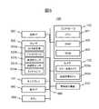
- FIG. 1is a diagram showing an example of the appearance of the golf head-mounted display of Example 1 (hereinafter, may be referred to as a head-mounted display or HMD).
- HMDhead-mounted display
- the head-mounted display (HMD) 100has a transmissive display 101, a controller 102, a camera 103, a frame 104 for supporting each part, and a button 105 for the user to wear.
- the transmissive display 101is also a kind of head-up display, and the display device is made of a half mirror so that the outside can be seen.
- FIG. 1shows a display for both eyes, a display device may be attached to only one eye. Further, a display using a holographic element may be used. By using a half mirror of an optical multilayer film, it is possible to see through the outside while displaying only necessary information on the surface of the display plate.
- the camera 103includes a color image camera 103a and a distance image camera 103b.
- the distance image camera 103bis a camera capable of measuring three-dimensional information using the flight time of light, such as a TOF camera (Time-of-Flight Camera) or the like.
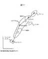
- FIG. 2is an explanatory diagram of an operation of setting the launch direction of the ball in the HMD of the first embodiment. In order to help the understanding of the invention, a method of using the HMD when playing golf will be described, and then how to realize it with the HMD of the embodiment will be described.
- the playermarks the tee ground with a predetermined movement, for example, the movement of the tip of the hand 201, with the launch direction as the target position via the display 101 of the HMD 100.
- the marked target positionis captured by the camera 103 and stored in the internal coordinate system managed by the HMD.
- the playercan recognize the green 203 and the flag 204 through the transmissive display 101 of the HMD 100.
- the depth coordinate of the point pointed by the finger at this timeis a predetermined value, for example, 200 yards ahead.
- Reference numeral 202denotes an edge of the display 101 of the HDM 100.
- the camera 103starts high-speed imaging and performs imaging at a high frame rate.
- the HMD 100calculates the marked direction with a 3D sensor in the internal coordinate system of the HMD 100, and displays an arrow toward the marked direction coordinate.
- the start of high-speed imagingmay be manually instructed by using the button 105 of the HMD or the like.
- FIG. 3is a diagram showing an example of a display at the time of addressing on the head-mounted display of the first embodiment.
- the playercan recognize the club 301 and the ball 302 through the transmissive display 101 of the HMD 100.
- the HMD 100displays an arrow 311 indicating the marked direction described in FIG. When the player faces the marked direction, highlight it by changing the color of the arrow or the density, brightness, solid line / dotted line of the display. If the player is addressing to the right of the marked direction, the arrow 313 is displayed, and if the player is addressing to the left of the marked direction, the arrow 312 is displayed.
- the color image camera 103a of the HMD 100photographs the ball 302 and the club 301, and the HMD 100 detects that the ball 302 and the club 301 are in the address state by image recognition. If the system is registered by the user in advance, the club to be used can be accurately determined by comparing with the image of the registered club. The determination of the club to be used is the information necessary for more accurate calculation of the flight distance of the ball.
- the HMDanalyzes the ball launch speed, the head speed, the meet rate, and the spin amount from the image.
- the existing simulation techniquemay be applied.
- the HMD 100 of the first embodimentstores the launch direction (direction of the target position) designated by the player on the tee ground, the fairway, or the like by using the internal coordinate system of the HMD 100. Even if you rotate your body when entering the address, you can display the direction marked at the time of address as an AR (Augmented Reality) as a virtual object based on the coordinates of the memorized launch direction, and take the address in the correct direction. be able to.
- ARAugmented Reality
- FIG. 4is a diagram showing an example of the display of the HMD of the first embodiment. It is the figure which image-processed the state which hit the ball and displayed the result of having analyzed the ball launch speed, the head speed, the meet rate, and the spin amount from the image in the display area 401 of the display 101.
- FIG. 4shows that the image-processed ball launch speed, head speed, meet rate, and spin amount indicate that the ball fall prediction point 402 is AR-displayed.
- the playercan identify the drop point of the ball on the actual course, so that the time for searching for the ball can be shortened, and as a result, the lost ball can be reduced.
- FIG. 5is a diagram showing an example of the hardware configuration of the head-mounted display of the first embodiment.
- the HMD 100 of the first embodimentbasically has the same configuration as a general-purpose computer (information processing device). That is, as shown in FIG. 5, the HMD 100 includes a controller 102, a camera 103, a display 101, a voice interface (I / F) 540, a communication I / F 520, a sensor 530, a line-of-sight detection device 510, and the like. It includes a button 550 and a bus 560 that electrically connects each part.
- I / Fvoice interface
- the controller 102performs various processes according to a predetermined program such as the image processing unit 601 shown in FIG.
- the controller 102AR-displays virtual objects such as the arrow 311 in FIG. 3, the display area 401 in FIG. 4, and the fall prediction point 402 at a predetermined position on the display 101, for example.
- the controller 102 of the first embodimentincludes a CPU 501, a RAM 502, and a ROM 503.
- the CPU 501realizes various functions by loading a program previously stored in the ROM 503 into the RAM 512 and executing the program.
- the RAM 502 and the ROM 503are collectively referred to as a storage device 630 (see FIG. 6) when it is not necessary to distinguish them.
- the controller 102is arranged on the frame 104, for example.
- the camera 103includes a color image camera 103a and a distance image camera 103b.
- the color image camera 103acaptures a shooting range including the user's field of view and acquires a color image.
- the distance image camera 103bacquires a distance image in a shooting range substantially the same as that of the color image camera 103a.
- the camera 103(color image camera 103a and distance image camera 103b) captures the marked target position shown in FIG. 2 and stores it in the storage device 630 in the internal coordinate system managed by the HMD by the controller 102.
- the shooting rangeis arranged at a position where shooting is possible.
- both / or either of the color image camera 103a and the distance image camera 103bmay have a memory (not shown) for temporarily storing an image at the time of imaging at a high frame rate.
- the display 101is a transmissive device that displays the image acquired by the camera 103 and the display data generated in the HMD 100.
- the display 101is composed of, for example, a transmissive liquid crystal device, an organic EL device, an optical scanning type device using MEMS (micro electronics mechanical systems), or the like.
- MEMSmicro electronics mechanical systems
- the deviceis not limited to this, and any device can be used as long as it can realize a transmissive display structure in which the other side of the display 101 can be seen through while displaying an image on the display 101.
- the transmissive display 101is supported in front of one or both eyes of the user.
- the display 101can take an arbitrary shape.
- the display 101may include right and left display panels, and the display 101 may display one or more UI objects of the graphical user I / F.
- the voice I / F540is, for example, a voice output device such as a microphone, a speaker, and a buzzer.
- the voice I / F 540inputs a sound from the outside world and outputs a sound created in the HMD 100 or a sound such as a voice or music transmitted via the communication I / F 520.
- the voice I / F 520may not be provided.
- the communication I / F520is provided with a code circuit, a decoding circuit, an antenna, etc., and transmits / receives data (data communication) to / from another device which is an external device via a network.
- the communication I / F 520is an I / F that connects to the network via an access point or the like (not shown) or a base station or the like of a mobile telephone communication network (not shown). ..
- the HMD 100transmits / receives data to / from each server connected to the network via the communication I / F 520.
- the button 550is for turning on / off the power of the HMD 100, switching the operation mode, and inputting the start timing of a predetermined operation to the HMD 100 by the user.
- Button 550corresponds to button 105 in FIG.
- the connection between the HMD100 and the access pointis performed by, for example, a wireless communication method such as Wi-Fi (registered trademark) or Bluetooth (registered trademark) or a communication method such as others.
- a wireless communication methodsuch as Wi-Fi (registered trademark) or Bluetooth (registered trademark) or a communication method such as others.
- the connection between the HMD100 and the base station of the mobile telephone communication networkis, for example, W-CDMA (registered trademark) (Wideband Code Division Multiple Access) method, GSM (registered trademark) (Global System for Mobile communications) method, LTE (LTE). It is performed by the Term Evolution) method or other communication methods such as 5G.
- the sensor 530detects the current position, tilt, speed, user operation, etc. of the HMD100.
- the HMD 100includes, for example, a position information acquisition sensor such as a GPS receiver 531a, a gyro sensor 531b, an acceleration sensor 531c, a geomagnetic sensor 531d, a touch sensor 531e, and the like.
- the sensor 530does not have to include all of them.
- the line-of-sight detection device 510detects the user's line-of-sight direction.
- the line-of-sight detection device 510is realized by, for example, a line-of-sight detection camera that detects the line-of-sight direction of the user.
- the line-of-sight detection camerais attached so as to include the iris, pupil, etc. of the user's eye in the imaging range.
- FIG. 6is a functional block diagram of the function related to the virtual object display processing of the HMD 100 of the first embodiment.
- the controller 102realizes the functions of the image processing unit 601, the display control unit 610, and the audio output control unit 625.
- the display control unit 610includes a space recognition unit 611, an instruction reception unit 622, a display data generation unit 623, and a display correction unit 624.
- Each functionis realized by the CPU 501 loading the program stored in the ROM 503 into the RAM 502 and executing it.
- the storage device 630stores color image data 631, distance image data 632, spatial recognition data 633, virtual object data (virtual OJT data) 634, audio data 636, and map data 638.
- the map data 638is not always necessary in the first embodiment.
- the color image data 631is an image acquired by the color image camera 103a.
- the distance image data 632is an image acquired by the distance image camera 103b.
- the image processing unit 601stores the color image and the distance image acquired by the color image camera 103a and the distance image camera 103b in the storage device 630 as the color image data 631 and the distance image data 632, respectively.
- the color image and the distance imageare acquired substantially synchronously.
- the space recognition unit 611is an internal coordinate system generated based on the output from the sensor 530 inside the HMD, recognizes the surrounding real space, and stores the result as space recognition data 633 in the storage device 630. To do. The recognition is performed using the color image data 631 and the distance image data 632 acquired substantially at the same time.
- the space recognition unit 611generates space recognition data 633, which is three-dimensional data (three-dimensional map) of the structure in the shooting range, from each image data at predetermined time intervals according to the scanning operation of the user, and stores the storage device. Store in 630.
- the surrounding scanis performed, for example, immediately after startup, periodically as an initial setting, or by operating a button of the user.
- the map data 638is absolute coordinate system data, and stores the map information of the golf course downloaded from the communication I / F 520 via the Internet in the storage device 630 by GNSS (Global Navigation Satellite System / Global Positioning Satellite System).
- the map dataincludes the course layout of each hole of the golf course.
- the course layoutalso includes information on the distance from the teeing ground to the tee and the location and size of obstacles such as bunkers, ponds and OBs.
- the space recognition data 633is created, for example, in the world coordinate system (coordinate system including absolute coordinates) that defines the entire three-dimensional space.
- the local coordinate system (internal coordinate system) of the HMD100which is specified by the position and orientation (initial posture) of the HMD100 main body when the instruction to start spatial recognition is received as the origin and each axial direction of this world coordinate system. Includes) origin and each axial direction.
- the originis a predetermined position on the display 101 of the HMD100
- the inside of the display 101is the xy plane
- the z-axis directionis the direction perpendicular to the xy plane (display 101 plane).
- the amount of displacement and the amount of rotation of the local coordinate system of the HMD100 by the user's scanning operation with respect to the world coordinate systemare calculated using the data obtained by various sensors 530.
- spatial recognitionis performed using, for example, existing technology such as Spatial Mapping. That is, the HMD 100 of the first embodiment scans the surroundings by the color image camera 103a and the distance image camera 103b. Then, using the result, the space recognition unit 611 generates three-dimensional data by using an application such as Spatial Mapping.
- the spatial recognition data 633is held as, for example, mesh data.
- the space recognition unit 611can recognize the material and type of the constituents within the photographing range by the spatial understanding. That is, it is possible to recognize whether the structure is, for example, a "wall", a "floor”, or a "ceiling".
- the space recognition unit 611stores these recognition results in the storage device 630 as attribute data of the space recognition data 633.
- the instruction receiving unit 622receives display instructions and operation instructions for the virtual object displayed on the display 101.
- the display instruction and the operation instructioninclude, for example, those by the line of sight (gaze) and those by the movement of the fingers (gesture).
- the line-of-sight direction information used for gazeis detected using, for example, the line-of-sight detection device 510.
- Gesturesinclude, for example, click events (air taps), tap and hold, bloom, etc. for operation points of virtual objects.
- the instruction receiving unit 622detects the movement of the fingers in the gesture frame provided within the shooting range of the color image camera 103a and the distance image camera 103b, and detects display instructions, operation instructions, and the like.
- the instruction reception unit 622extracts the data of the instructed virtual object from the virtual object data 634, and causes the display data generation unit 623 described later to generate display data.
- the instruction reception unit 622detects the operation and notifies the display data generation unit 623 described later.
- the display data generation unit 623generates display data from the virtual object data 634 to display the instructed virtual object at a predetermined position on the display 101 in a predetermined shape according to the user's instruction via the instruction reception unit 622. For example, in addition to the arrow 311 in FIG. 3 indicating the marking in the direction supported by the fingertip 201 in FIG. 2, virtual objects such as the display area 401 and the predicted fall point 402 in FIG. 4 calculated by the HMD are displayed on the display 101. Generated to do.
- FIG. 7is a flowchart showing the processing operation of the HMD 100.
- step S71the image acquired by the image processing unit 601 from the camera 103 is shown in FIG. 2 by the instruction receiving unit 622 with respect to the three-dimensional data of the structure in the photographing range generated by the space recognition unit 611.
- the useracquires the position (marking position) specified by the fingertip 201.
- the marking positionmay be simply stored by detecting the operation for marking the target position via the camera 103.
- step S72the display data generation unit 623 displays a target arrow on the display 101 toward the internal coordinate direction marked by the integrated value of the output from each sensor 530.
- the marked launch directionis determined. calculate.
- An arrow pointing in the marked directionis read from the virtual object data 634, processed in 3D, and displayed on the display 101 of the HMD 100.
- step S73the image processing unit 601 of the controller 102 detects the address state from the positional relationship between the ball and the club head from the color image from the color image camera 103a.
- the output of each sensor 530detects that the player has entered the address state.
- the display 101is virtually displayed in the direction of.
- step S74the controller 102 controls the camera 103 to shoot at a high frame rate, and the camera 103 starts shooting at a high frame rate.
- step S75the image processing unit 601 of the controller 102 detects the shot state by image processing, and calculates the fall prediction point from the detected ball speed and spin amount.
- step S76the image processing unit 601 of the controller 102 calculates the fall prediction point from the calculated ball speed and spin amount.
- step S77the display data generation unit 623 reads the display data for displaying the calculated fall prediction point from the virtual object data 634 and displays it as a virtual object on the display 101 under the control of the display control unit 610 of the controller 102.
- the playercan take an address toward the correct target direction.
- the time for searching for the ballcan be shortened, and as a result, the lost ball can be reduced.
- Example 2is an application using the HMD map data 638.
- FIG. 8is an application for automatically registering a score by linking the HMD 100 and the smartphone 801.
- the HMD 100 shown in FIG. 1 and the smartphone 801are connected by wireless communication such as Bluetooth.
- the controller 102 of the HMD 100identifies the hall information corresponding to the current position of the player from the map data 638 and the GPS receiver 531a.
- the GPS information from the GPS receiver 531aincludes information indicating the current position. In the example of FIG. 8, it is displayed that the player is in the second hole 810.
- the screen 810 of the smartphone 801acquires and displays the hole number and the scorecard information indicating the number of pars and the distance (number of yards) of the hole from the map data 638.
- the scorecard informationdoes not have to include information about distance.
- the controller 102transmits the scorecard information corresponding to the specified hall information to an external device such as a smartphone 801 via the communication interface 520.
- the smartphone 801displays the scorecard information transmitted from the HMD 100 as shown in FIG.
- the HMD 100 shown in FIG. 8can recognize the action of hitting a ball by image processing as described in the first embodiment, if the hole number is specified from the position of the player by the GPS receiver 531a, the number of shots of each hole can be determined. It can be entered automatically. Since the shot and putt operations can be distinguished based on the shape of the club photographed by the camera 103 and the head speed calculated by image processing, the number of shots and the number of putts in each hole can also be automatically input. That is, the controller 102 identifies the hole number to be played by the user based on the GPS information from the GPS receiver 531a and the map data 638, and analyzes the image taken by the camera 103 for the specified hole number. As a result, the number of shots and the number of putts in each hole can be calculated and stored in the storage device 630, or the score can be displayed on the display 101.
- FIG. 9is a diagram showing an example of the display of the HMD of the second embodiment.
- FIG. 9shows an example in which the results of analyzing the ball launch speed, head speed, meet rate, and spin amount from the image are displayed on the display 101.
- the HMD100By providing the HMD100 with the GPS receiver 531a and the map data 638, it is possible to determine which point in which hole of the golf course the player is. Based on the GPS receiver 531a, the map data 638, and the ball fall prediction point described in the first embodiment, when the ball fall prediction point corresponds to a bunker, a pond, an OB, a one-penalty area, etc., the display control of the controller 102 is performed.
- the unit 610controls the display 101 to change the color of the fall prediction point display or display characters.
- the controller 102can also calculate the distance to the green edge before the shot of the player from the GPS information from the GPS receiver 531a and the map data 638 and display it on the display 101.
- the scorecan be registered by linking the HMD and the smartphone. Further, according to the second embodiment, the number of shots and the number of putts can be automatically registered from the GPS information, the map data, and the operation of the shots and putts that can be grasped by the HMD.
- the absolute coordinate systemis a coordinate system obtained from latitude and longitude information obtained from satellites.
- the absolute coordinate systemis shown by x', y', and z'.
- the internal coordinate systemis the internal coordinate system of the HMD100, which always performs inertial calculation from the accelerometer, gyro, and compass to calculate its own position and orientation.
- FIG. 10Bshows the internal coordinate system with x, y, and z. This internal coordinate system gradually deviates from the absolute coordinate system obtained from GPS information due to errors in the gyro, compass, accelerometer, and integration error. In particular, the error of the compass is large, and therefore, as shown in FIG. 10B, the integration of the deviation in the rotation direction is large.
- the position of the bunker at the position of 101b in the absolute coordinate systemis grasped as 101a in the internal coordinate system.
- the fall prediction point 402is near the bunker in the absolute coordinate system, it is predicted that the ball will fall to a place other than the bunker, so that it is not possible to determine or display that the ball may have entered the bunker. This is because the bunker 101, the map data of the hole, and the ball fall prediction point 402 are calculated in the internal coordinate system. It is necessary to correct the error with the absolute coordinate system accumulated in this internal coordinate system.
- FIG. 11is a diagram showing correction of the coordinate system. It is a figure explaining the method of adjusting the internal coordinate system of HMD100 to the absolute coordinate system.
- FIG. 11shows the positions P1 (x'1, y'1), P2 (x2, y2), and P3 (x3, y3) where the player hit the shot on the map data of the golf course.
- the locus 1 and the locus 2represent a locus that linearly connects the positions where the player hits the shot.
- the alternate long and short dash lineindicates that it is parallel to the x-axis of the absolute coordinate system.
- the locus 1 between the position P1 and the position P2can be represented by an angle ⁇ and a length L with respect to the x-axis of the absolute coordinate system.
- the internal coordinate systemis corrected (calibrated) by replacing the angle with respect to the x-axis when moving from the P1 point to the P2 point obtained by integrating the output of the internal sensor 530 with ⁇ and the distance with L. ..
- the calibration timingmay be at regular time intervals, shot points, and the like.
- the calibrationmay be performed by another method. For example, the player manually identifies the bunker position and the pin position of the hole, which are easy to identify on the course, so that the bunker position and the pin position virtually displayed based on the map data are adjusted to the positions specified by the user. You may go by that.
- FIG. 12is a flowchart showing the processing operation of the HMD 100.
- the steps that perform the same processing as in FIG. 7are designated by the same reference numerals. That is, steps S71 to S75, and steps S76 and S77 correspond to the processes of steps S71 to S77 described with reference to FIG. 7.
- the process of step S121is performed between steps S75 and S76.
- Step S121is a step executed by the display correction unit 624 in order to correct the internal coordinates described with reference to FIG. 11, and stores the shot point (absolute coordinates) this time.
- Thisis a process of recording the absolute coordinates of the position P2 in FIG. Calculate the slope with the previous shot point (absolute coordinates).
- the slope of the position P1 in FIG. 11 with respect to the shot point (absolute coordinates)is calculated.
- the slope obtained by the integral calculation of the sensor 530is corrected as described above.
- the playercan grasp the correct situation of the ball fall prediction point by matching the internal coordinate system of the HMD with the absolute coordinate system.
- the playercan grasp the correct shot target from the map data before the shot.
- 100Head-mounted display, 101: Display, 102: Controller, 103: Camera, 104: Frame, 105: Button, 501: CPU, 502: RAM, 503: ROM, 510: Line-of-sight detector, 520: Communication I / F, 530: Sensor, 540: Voice I / F.
Landscapes
- Health & Medical Sciences (AREA)
- General Health & Medical Sciences (AREA)
- Physical Education & Sports Medicine (AREA)
- User Interface Of Digital Computer (AREA)
- Processing Or Creating Images (AREA)
Abstract
Description
Translated fromJapanese本発明は、ヘッドマウントディスプレイに関する。例えば、ゴルフ用のヘッドマウントディスプレイの技術に関する。The present invention relates to a head-mounted display. For example, it relates to the technology of a head-mounted display for golf.
従来、様々なゴルフシミュレーション装置が考案され、ショットデータの確認やアプローチの反復などといったスキルアップのための練習はもちろんのこと、あたかも、実際のコースで、ニアピンやマッチプレイ等が楽しめるようになってきている。Conventionally, various golf simulation devices have been devised, and it has become possible to enjoy near-pin and match play as if it were an actual course, as well as practice for skill improvement such as confirmation of shot data and repetition of approach. ing.
ゴルフシミュレーション装置では、プレーヤの打った球を解析し、ボールの飛距離や落下地点を計算することで、ディスプレイに疑似的に再現されたコース上で、プレーヤが実際のプレイしているように感じさせることができる。The golf simulation device analyzes the ball hit by the player and calculates the flight distance and drop point of the ball, so that the player feels as if he or she is actually playing on the course simulated on the display. Can be made to.
プレーヤの打った球を解析し、ボールの飛距離や落下地点を計算する技術として、特許文献1がある。
この特許文献1に記載された技術では、ゴルフボールを打撃したことを検知するトリガーセンサと、打撃後のゴルフボールを撮像するCCDカメラと、任意の条件での空力係数データを含む各種データを記憶し、CCDカメラにより撮像された画像データから得られたゴルフボールの速度等のデータと空力係数データを含む各種データとを用いてゴルフボールの弾道軌道や飛距離を計算するPCと、PCによる計算結果を基にゴルフボールの弾道軌道や飛距離を表示するモニタとを備える。特に、特許文献1では、実際にボールを回転させるゴルフボール回転装置を用いて空力係数を測定することで、ゴルフボールの弾道軌道や飛距離を計算している。In the technique described in
しかしながら、上記特許文献1を含め、多くのゴルフシミュレーション装置は、実際のゴルフコースで使用することを前提としていない。例えば、実際のゴルフ場における、正しい方向に向かってアドレスをとること等、プレーヤの支援をすることについては言及されていない。However, many golf simulation devices, including
そこで、本発明の目的は、実際のゴルフコースにおいて、正しい目標方向に向かってアドレスをとることを支援するゴルフ用のヘッドマウントディスプレイを提供することにある。Therefore, an object of the present invention is to provide a head-mounted display for golf that assists in taking an address toward a correct target direction in an actual golf course.
また、本発明の他の目的は、ボールを探す時間を短縮でき、結果としてロストボールを減少させることができるゴルフ用のヘッドマウントディスプレイを提供することにある。Another object of the present invention is to provide a head-mounted display for golf, which can shorten the time for searching for a ball and, as a result, reduce the number of lost balls.
上記目的を達成するため、本発明のゴルフ用のヘッドマウントディスプレイの一態様は、ユーザの所定動作に応答して、目標位置を取り込むカメラと、目標位置をヘッドマウントディスプレイが管理する内部座標系で記憶する記憶装置と、ユーザの動きを検出するセンサと、センサの出力を積分するコントローラと、コントローラの積分結果に基づき、目標位置の方向を示す第1の仮想オブジェクトを表示する透過型ディスプレイとを有する。In order to achieve the above object, one aspect of the head-mounted display for golf of the present invention is a camera that captures a target position in response to a predetermined operation of the user and an internal coordinate system in which the target position is managed by the head-mounted display. A storage device for storing, a sensor for detecting the movement of the user, a controller for integrating the output of the sensor, and a transmissive display for displaying a first virtual object indicating the direction of the target position based on the integration result of the controller. Have.
また、上記目的を達成するため、本発明のゴルフ用のヘッドマウントディスプレイの一態様は、クラブによりゴルフボールを打つ状態を高速撮影するカメラと、カメラにより撮影された画像を解析し、ゴルフボールのボールスピードとスピン量を算出し、ボールスピードとスピン量に基づき、ゴルフボールの落下予測地点を算出するコントローラと、落下予測地点に第2の仮想オブジェクトを表示する透過型ディスプレイとを有する。Further, in order to achieve the above object, one aspect of the head mount display for golf of the present invention is to analyze a camera that captures a state of hitting a golf ball by a club at high speed and an image captured by the camera to analyze the image of the golf ball. It has a controller that calculates a ball speed and a spin amount, and calculates a golf ball fall prediction point based on the ball speed and the spin amount, and a transmissive display that displays a second virtual object at the fall prediction point.
本発明によれば、実際のゴルフコースにおいて、正しい目標方向に向かってアドレスをとることを支援できる。According to the present invention, it is possible to support taking an address in the correct target direction in an actual golf course.
また、ボールを探す時間を短縮でき、結果としてロストボールを減少させることができる。Also, the time to search for the ball can be shortened, and as a result, the lost ball can be reduced.
実施形態について、図面を参照して説明する。なお、以下に説明する実施形態は特許請求の範囲に係る発明を限定するものではなく、また実施形態の中で説明されている諸要素及びその組み合わせの全てが発明の解決手段に必須であるとは限らない。The embodiment will be described with reference to the drawings. It should be noted that the embodiments described below do not limit the invention according to the claims, and all of the elements and combinations thereof described in the embodiments are indispensable for the means for solving the invention. Is not always.
以下の説明では、[AAAテーブル]の表現にて情報を説明することがあるが、情報は、どのようなデータ構造で表現されていてもよい。すなわち、情報がデータ構造に依存しないため、[AAAテーブル]は[AAA情報]と説明することができる。In the following explanation, information may be explained by the expression of [AAA table], but the information may be expressed by any data structure. That is, since the information does not depend on the data structure, the [AAA table] can be described as [AAA information].
また、以下の説明では、[CPU]は、処理部となり、1以上のプロセッサを含むCentral Processing Unitである。プロセッサは、処理の一部または全部を行うハードウェア回路を含んでもよい。Further, in the following description, the [CPU] is a processing unit and is a Central Processing Unit including one or more processors. The processor may include hardware circuits that perform some or all of the processing.
また、以下の説明では、[プログラム]を動作の主体として処理を説明する場合があるが、プログラムは、CPUによって実行されることで、定められた処理を、適宜に記憶資源(例えばメモリ)等を用いながら行うため、実際の処理の主体はCPUである。従って、プログラムを動作の主体として説明された処理は、プロセッサが処理主体と説明されても良い。また、プロセッサが行う処理の一部又は全部をApplication Specific Integrated Circuit(ASIC)やField‐Programmable Gate Array(FPGA)等のハードウェア回路が行っても良い。Further, in the following description, the process may be described with the [program] as the main body of operation, but the program is executed by the CPU to appropriately perform the specified process as a storage resource (for example, memory) or the like. The main body of the actual processing is the CPU because it is performed while using. Therefore, in the process described with the program as the subject of operation, the processor may be described as the subject of operation. In addition, a hardware circuit such as an Application Specific Integrated Circuit (ASIC) or a Field-Programmable Gate Array (FPGA) may perform a part or all of the processing performed by the processor.
<システム構成>
まず、本発明の一実施形態に係るシステムについて説明する。<System configuration>
First, a system according to an embodiment of the present invention will be described.
図1は、実施例1のゴルフ用のヘッドマウントディスプレイ(以下、ヘッドマウントディスプレイ、或いはHMDと記載する場合がある)の外観の一例を示す図である。FIG. 1 is a diagram showing an example of the appearance of the golf head-mounted display of Example 1 (hereinafter, may be referred to as a head-mounted display or HMD).
ヘッドマウントディスプレイ(HMD)100は、透過型ディスプレイ101、コントローラ102、カメラ103、各部を支え、ユーザが装着するためのフレーム104、ボタン105を有する。透過型ディスプレイ101は、ヘッドアップディスプレイの一種でもあり、ディスプレイ装置はハーフミラーでできており、外の様子を見ることができる。図1では、両目用のディスプレイを示しているが、片目のみにディスプレイ装置がついているものであってもよい。また、ホログラフィック素子を用いたディスプレイであっても良い。光学多層膜のハーフミラーを用いると、必要な情報のみ表示板の表面に表示しながら外の様子をシースルーで見ることが可能となる。The head-mounted display (HMD) 100 has a
カメラ103は、カラー画像カメラ103aと距離画像カメラ103bで構成される。距離画像カメラ103bは、例えばTOFカメラ(トフカメラ、Time-of-Flight Camera)等のように、光の飛行時間を利用して三次元情報を計測可能なカメラである。
<HMDの利用方法>
図2は、実施例1のHMDでボールの打ち出し方向を設定する動作の説明図である。発明の理解を助けるため、ゴルフのプレイ時におけるHMDの利用方法について説明し、その後、実施例のHMDで如何にそれを実現するかを説明する。The
<How to use HMD>
FIG. 2 is an explanatory diagram of an operation of setting the launch direction of the ball in the HMD of the first embodiment. In order to help the understanding of the invention, a method of using the HMD when playing golf will be described, and then how to realize it with the HMD of the embodiment will be described.
まず、プレーヤはティーグランドにて、HMD100のディスプレイ101を介して打ち出し方向を目標位置として、所定の動作、例えば、手の先201の動きでマーキングする。マーキングされた目標位置は、カメラ103で取り込まれ、HMDが管理する内部座標系で記憶される。プレーヤはHMD100の透過型のディスプレイ101を介してグリーン203や旗204を認識することができる。この時の指でポイントした先の奥行座標は所定値、例えば200ヤード先とする。尚、202は、HDM100のディスプレイ101の縁である。First, the player marks the tee ground with a predetermined movement, for example, the movement of the tip of the hand 201, with the launch direction as the target position via the
次に、HMD100は、クラブ、ボールを画像認識してプレーヤがアドレスの姿勢をとったと認識すると、カメラ103により高速撮像開始し、高フレームレートの撮像を行う。HMD100は、マーキングした方向をHMD100の内部座標系で3Dセンサにて計算して、マークした方向座標に向かう矢印を表示する。尚、高速撮像開始は、HMDのボタン105等を使って手動で指示するようにしてもよい。Next, when the
図3は、実施例1のヘッドマウントディスプレイでアドレス時の表示の一例を示す図である。プレーヤはHMD100の透過型のディスプレイ101を介してクラブ301、ボール302を認識することができる。HMD100は、図2で説明したマーキングした方向を示す矢印311を表示する。プレーヤが、マークした方向を示す正対したら矢印の色もしくは表示の濃さ、輝度、実線/点線を変えるなど強調表示するようにする。尚、プレーヤがマーキングした方向より右方向にアドレスしている場合には矢印313を表示し、マーキングした方向より左方向にアドレスしている場合には矢印312表示する。この時、HMD100のカラー画像カメラ103aは、ボール302及びクラブ301を撮影し、画像認識によってアドレス状態にあることをHMD100が検知する。予めユーザによって登録されるようなシステムであれば、登録されたクラブの画像と比較することで、使用されるクラブを正確に判別することができる。使用するクラブの判別は、より高精度なボールの飛距離計算に必要な情報となる。FIG. 3 is a diagram showing an example of a display at the time of addressing on the head-mounted display of the first embodiment. The player can recognize the
ショット時はクラブヘッドが図の右から左側に降りてきてボールを打つ状態を画像処理で認識する。このときHMDは、ボール打ち出しスピード、ヘッドスピード、ミート率、スピン量を画像から分析する。分析方法については、既存のシミュレーション技術を応用すればよい。At the time of shot, the state where the club head descends from the right to the left in the figure and hits the ball is recognized by image processing. At this time, the HMD analyzes the ball launch speed, the head speed, the meet rate, and the spin amount from the image. As for the analysis method, the existing simulation technique may be applied.
通常、プレーヤはアドレスに入る前にボールの打ち出し方向を正面で確認し、約90度回転してアドレスに入る。この打ち出し方向を確認した後アドレスに入る段階で、プレーヤは正しい打ち出し方向を見失い、間違った方向にアドレスをとることで、ミスショットにつながる。実施例1のHMD100は、プレーヤがティーグランドやフェアウェイ等で指定された打ち出し方向(目標位置の方向)を、HMD100の内部座標系を用いて記憶する。アドレスに入る際に体を回転させても、アドレス時にマーキングした方向を、記憶した打ち出し方向の座標に基づいて矢印を仮想オブジェクトとしてAR(Augmented Reality、拡張現実)表示でき、正しい方向にアドレスをとることができる。Normally, the player confirms the launch direction of the ball from the front before entering the address, and rotates about 90 degrees to enter the address. At the stage of entering the address after confirming this launch direction, the player loses sight of the correct launch direction and takes the address in the wrong direction, which leads to a miss shot. The
図4は、実施例1のHMDの表示の一例を示した図である。ボールをヒットした状態を画像処理し、ボール打ち出しスピード、ヘッドスピード、ミート率、スピン量を画像から分析した結果をディスプレイ101の表示領域401に表示した図である。FIG. 4 is a diagram showing an example of the display of the HMD of the first embodiment. It is the figure which image-processed the state which hit the ball and displayed the result of having analyzed the ball launch speed, the head speed, the meet rate, and the spin amount from the image in the
また、図4には、画像処理されたボール打ち出しスピード、ヘッドスピード、ミート率、スピン量からボールの落下予測地点402をAR表示されたことを示している。これにより、プレーヤは実際のコースでボールの落下地点を特定できるので、ボールを探す時間を短縮でき、結果としてロストボールを減少させることができる。
<HMDのハードウェア構成>
図5は、実施例1のヘッドマウントディスプレイのハードウェア構成の一例を示した図である。Further, FIG. 4 shows that the image-processed ball launch speed, head speed, meet rate, and spin amount indicate that the ball
<Hardware configuration of HMD>
FIG. 5 is a diagram showing an example of the hardware configuration of the head-mounted display of the first embodiment.
実施例1のHMD100は、基本的に汎用のコンピュータ(情報処理装置)と同様の構成を有する。すなわち、HMD100は、図5に示すように、コントローラ102と、カメラ103と、ディスプレイ101と、音声インタフェース(I/F)540と、通信I/F520と、センサ530と、視線検出装置510と、ボタン550と、各部を電気的に接続するバス560とを備える。The
コントローラ102は、図6に示した、例えば画像処理部601等、予め定めたプログラムに従って、各種の処理を行う。実施例1では、コントローラ102は、例えば、ディスプレイ101の所定の位置に、図3の矢印311や図4の表示領域401、落下予測地点402等の仮想オブジェクトをAR表示させる。The
実施例1のコントローラ102は、CPU501と、RAM502と、ROM503と、を備える。CPU501は、予めROM503に格納されたプログラムを、RAM512にロードして実行することにより、各種の機能を実現する。なお、RAM502およびROM503は、特に区別する必要がない場合は、両者を合わせて記憶装置630(図6参照)と呼ぶ。なお、コントローラ102は、例えば、フレーム104上に配置される。The
カメラ103は、カラー画像カメラ103aと、距離画像カメラ103bと、を備える。カラー画像カメラ103aは、ユーザの視野範囲を含む撮影範囲を撮影し、カラー画像を取得する。また、距離画像カメラ103bは、カラー画像カメラ103aと略同範囲の撮影範囲の距離画像を取得する。カメラ103(カラー画像カメラ103aおよび距離画像カメラ103b)は、図2で示したマーキングされた目標位置を取り込み、コントローラ102によってHMDで管理する内部座標系で記憶装置630に記憶される。例えば、フレーム104の最前部において、上記撮影範囲を撮影可能な位置に配置される。なお、カラー画像カメラ103a距離画像カメラ103bの両方/またはいずれかは、高速フレームレートでの撮像時の画像を一時的に記憶するメモリ(図示せず)を持っていてもよい。The
ディスプレイ101は、カメラ103で取得した画像、HMD100内で生成された表示データが表示される透過型デバイスである。ディスプレイ101は、例えば、透過型の液晶デバイスや有機ELデバイス、あるいはMEMS(micro electro mechanical systems)を用いた光走査型のデバイス等で構成される。しかしながら、デバイスはこれに限定されず、ディスプレイ101上に映像を表示しつつ、ディスプレイ101の向こう側が透けて見える透過型ディスプレイ構造を実現可能なデバイスであればよい。The
実施例1のHMD100では、透過型のディスプレイ101が、ユーザの片眼または両眼の前で支持される。なお、ディスプレイ101は、任意の形状を撮ることができる。ディスプレイ101は、右および左の表示パネルを備えてもよい、また、ディスプレイ101には、グラフィカルユーザI/Fの1つまたは複数のUIオブジェクトが表示されてもよい。In the
音声I/F540は、例えば、マイク、スピーカ、ブザー等の音声出力装置である。音声I/F540は、外界の音の入力と、HMD100内で作成した音や通信I/F520を介して送られてくる音声や音楽等の音の出力とを行う。実施例1では、音声I/F520は、備えなくてもよい。The voice I / F540 is, for example, a voice output device such as a microphone, a speaker, and a buzzer. The voice I /
通信I/F520は、符号回路や復号回路、アンテナ等を備え、ネットワークを介して、外部デバイスである他装置とのデータの送受信(データ通信)を行う。実施例1では、通信I/F520は、図示を省略したアクセスポイント等を介して、または、図示を省略した移動体電話通信網の基地局等を介して、ネットワークと接続するI/Fである。通信I/F520を介して、HMD100は、ネットワークに接続された各サーバとのデータ送受信を行う。The communication I / F520 is provided with a code circuit, a decoding circuit, an antenna, etc., and transmits / receives data (data communication) to / from another device which is an external device via a network. In the first embodiment, the communication I /
ボタン550はHMD100の電源ON/OFFや、動作モードの切り替え、ユーザが所定の動作の開始タイミングをHMD100に入力するためのものである。ボタン550は、図1のボタン105に対応する。The
HMD100とアクセスポイントとの接続は、例えば、Wi-Fi(登録商標)やBluetooth(登録商標)等の無線通信方式やその他などの通信方式により行われる。HMD100と移動体電話通信網の基地局との接続は、例えば、W-CDMA(登録商標)(Wideband Code Division Multiple Access)方式やGSM(登録商標)(Global System for Mobile communications)方式、LTE(Long Term Evolution)方式、或いは5Gなどその他の通信方式によって行われる。The connection between the HMD100 and the access point is performed by, for example, a wireless communication method such as Wi-Fi (registered trademark) or Bluetooth (registered trademark) or a communication method such as others. The connection between the HMD100 and the base station of the mobile telephone communication network is, for example, W-CDMA (registered trademark) (Wideband Code Division Multiple Access) method, GSM (registered trademark) (Global System for Mobile communications) method, LTE (LTE). It is performed by the Term Evolution) method or other communication methods such as 5G.
センサ530は、HMD100の現在位置、傾き、速度、ユーザによる操作等を検出する。HMD100は、センサ530として、例えば、GPS受信機531a等の位置情報取得センサ、ジャイロセンサ531b、加速度センサ531c、地磁気センサ531d、タッチセンサ531e等を備える。なお、センサ530は、全てを備えなくてもよい。The
視線検出装置510は、ユーザの視線方向を検出する。視線検出装置510は、例えば、ユーザの視線方向を検出する視線検出カメラ等で実現される。視線検出カメラは、ユーザの眼の虹彩、瞳孔等を撮影範囲に含むよう取り付けられる。The line-of-
フレーム104は、ディスプレイ101、カメラ103、コントローラ102等のHMD100の構成品を支持する。
<HMDの機能ブロック>
次に、実施例1のコントローラ102が実現する、仮想オブジェクト表示に関連する機能を説明する。図6は、実施例1のHMD100の、仮想オブジェクト表示処理に関連する機能の機能ブロック図である。図6に示すように、コントローラ102は、画像処理部601と、表示制御部610と、音声出力制御部625の機能を実現する。また、表示制御部610は、空間認識部611と、指示受付部622と、表示データ生成部623と、表示補正部624と、を備える。The
<Functional block of HMD>
Next, the functions related to the virtual object display realized by the
各機能は、CPU501がROM503に格納されたプログラムを、RAM502にロードして実行することにより実現される。Each function is realized by the
また、記憶装置630には、カラー画像データ631と、距離画像データ632と、空間認識データ633と、仮想オブジェクトデータ(仮想OJTデータ)634と、音声データ636と、地図データ638が記憶される。尚、地図データ638は、実施例1では必ずしも必要ない。Further, the
カラー画像データ631は、カラー画像カメラ103aで取得した画像である。距離画像データ632は、距離画像カメラ103bで取得した画像である。The
画像処理部601は、カラー画像カメラ103aおよび距離画像カメラ103bでそれぞれ取得したカラー画像および距離画像を、カラー画像データ631および距離画像データ632として、記憶装置630に記憶する。実施例1では、カラー画像および距離画像は、略同期して取得される。The
空間認識部611は、HMD内部のセンサ530からの出力をもとに生成される内部座標系であり、周囲の実空間を認識し、その結果を、空間認識データ633として、記憶装置630に記憶する。認識は、略同時に取得したカラー画像データ631および距離画像データ632を用いて行う。The
空間認識部611は、ユーザのスキャン動作に従って、所定の時間間隔で、各画像データから、撮影範囲にある構造物の3次元データ(3次元マップ)である空間認識データ633を生成し、記憶装置630に記憶する。周囲のスキャンは、例えば、起動直後に、初期設定として定期的に、或いはユーザのボタン操作により行う。The
地図データ638は、絶対座標系のデータであり、GNSS(Global Navigation Satellite System / 全球測位衛星システム)で、通信I/F520からインターネット経由でダウンロードしたゴルフ場の地図情報を記憶装置630に記憶する。地図データには、ゴルフ場の各ホールのコースレイアウトが含まれる。コースレイアウトには、ティーグラウンドからティまでの距離や、バンカー、池やOBなどの障害の位置や大きさの情報も含まれる。The
空間認識データ633は、例えば、3次元空間全体を定義するワールド座標系(絶対座標を含む座標系)で作成される。一例として、このワールド座標系の原点および各軸方向として、空間認識開始の指示を受け付けた際の、HMD100本体の位置および向き(初期姿勢)で特定される、HMD100のローカル座標系(内部座標系を含む)の原点および各軸方向を用いる。この座標系では、例えば、HMD100本体の初期姿勢において、HMD100のディスプレイ101上の所定位置を原点として、ディスプレイ101内をxy平面として、z軸方向は、xy平面(ディスプレイ101面)に垂直な方向とする。The
なお、ユーザのスキャン動作によるHMD100のローカル座標系の、ワールド座標系に対する変位量および回転量は、各種センサ530により得られるデータを用いて算出される。The amount of displacement and the amount of rotation of the local coordinate system of the HMD100 by the user's scanning operation with respect to the world coordinate system are calculated using the data obtained by
なお、空間認識は、例えば、既存のSpatial Mapping等の技術を用いて行う。すなわち、実施例1のHMD100は、カラー画像カメラ103aおよび距離画像カメラ103bにより周囲をスキャンする。そして、その結果を用いて、空間認識部611が、Spatial Mapping等のアプリケーションを用いて3次元データを生成する。空間認識データ633は、例えば、メッシュデータとして保持される。It should be noted that spatial recognition is performed using, for example, existing technology such as Spatial Mapping. That is, the
また、このとき、3次元データだけでなく、構造物の種類を認識するSpatial Understandingも同時に行うよう構成してもよい。空間認識部611は、Spatial Understandingにより、撮影範囲内の構成物の材質、種類を認識できる。すなわち、構造物が、例えば、「壁」、「床」、「天井」のいずれであるか等を認識することができる。空間認識部611は、空間認識データ633の属性データとして、これらの認識結果を記憶装置630に格納する。Further, at this time, not only the three-dimensional data but also the physical understanding that recognizes the type of the structure may be performed at the same time. The
指示受付部622は、ディスプレイ101に表示される仮想オブジェクトに対する表示指示および操作指示を受け付ける。表示指示および操作指示は、例えば、視線(ゲイズ)によるもの、手指の動き(ジェスチャ)によるものなどがある。The
ゲイズに用いられる視線方向の情報は、例えば、視線検出装置510を用いて検出される。ジェスチャには、例えば、仮想オブジェクトの操作ポイントに対するクリックイベント(エアタップ)、タップアンドホールド、ブルーム等がある。指示受付部622は、カラー画像カメラ103aおよび距離画像カメラ103bの撮影範囲内に設けられたジェスチャフレーム内での手指の動きを検出し、表示指示、操作指示等を検出する。The line-of-sight direction information used for gaze is detected using, for example, the line-of-
例えば、表示指示を受け付けた場合、指示受付部622は、仮想オブジェクトデータ634から指示された仮想オブジェクトのデータを抽出し、後述の表示データ生成部623に表示データを生成させる。また、操作指示を受け付けた場合、指示受付部622は、当該操作を検出し、後述の表示データ生成部623に通知する。For example, when a display instruction is received, the
表示データ生成部623は、指示受付部622を介したユーザの指示に従って、仮想オブジェクトデータ634から、指示された仮想オブジェクトをディスプレイ101の所定の位置に所定の形状で表示させる表示データを生成する。例えば、図2の指先201によって支持された方向のマーキングを示す図3の矢印311の他、HMDによって算出される図4の表示領域401、落下予測地点402等の仮想オブジェクトを、ディスプレイ101に表示するために生成される。The display
指示受付部622の指示に従って生成された表示データをディスプレイ101に表示することにより、仮想オブジェクトは、ユーザの指示に従って、移動し、回転し、変形するよう表示される。
<HMDの処理動作>
図7は、HMD100の処理動作を示すフローチャートである。By displaying the display data generated according to the instruction of the
<HMD processing operation>
FIG. 7 is a flowchart showing the processing operation of the
まず、ステップS71では、カメラ103から画像処理部601で取得した画像を空間認識部611にて生成された撮影範囲にある構造物の3次元データに対し、指示受付部622により図2で示したようにユーザが指先201で指定した位置(マーキング位置)を取得する。単に、カメラ103を介して目標位置をマーキングするための動作を検出してマーキング位置を記憶しても良い。First, in step S71, the image acquired by the
次に、ステップS72で、表示データ生成部623は、各センサ530からの出力の積分値でマーキングした内部座標方向に向けて目標となる矢印を、ディスプレイ101に表示する。センサ530からの出力を積分演算した(この処理は所定時間ごとのCPU501への割り込み処理などで常に実行されている)HMD200の内部座標系の位置、向きをもとに、マーキングされた打ち出し方向を算出する。マーキングされた方向に向けた矢印を仮想オブジェクトデータ634から読み出し、3D演算処理してHMD100のディスプレイ101に表示する。Next, in step S72, the display
ステップS73で、コントローラ102の画像処理部601は、カラー画像カメラ103aからのカラー画像よりボール、クラブヘッドの位置関係からアドレス状態を検出する。または、各センサ530の出力により、プレーヤがアドレス状態に入ったことを検出する。例えば、ジャイロセンサ531bや加速度センサ531cの出力が小さくなったことによりアドレス状態に入ったことは検出できる。もしくは、ボタン105押下で行うようにしてもよい。つまり、コントローラ102は、ステップS71でマーキングし、目標位置を取り込んだ時からステップS73でプレーヤがアドレス状態に入るまでの、センサ530の出力を積分することで、目標位置を示す仮想オブジェクトの目標位置の方向に、ディスプレイ101に仮想的に表示させる。In step S73, the
ステップS74で、コントローラ102は、カメラ103の高フレームレートでの撮影するよう制御し、カメラ103は高フレームレートでの撮影を開始する。In step S74, the
ステップS75で、コントローラ102の画像処理部601は、画像処理でショット状態を検出し、検出したボールスピード、スピン量から落下予測地点を算出する。In step S75, the
ステップS76で、コントローラ102の画像処理部601は、算出したボールスピード、スピン量から落下予測地点を算出する。In step S76, the
ステップS77で、表示データ生成部623は、算出した落下予測地点を表示する表示データを仮想オブジェクトデータ634から読み出し、コントローラ102の表示制御部610の制御によってディスプレイ101に仮想オブジェクトとして表示する。In step S77, the display
実施例1によれば、実際のゴルフコースにおいて、HMDに目標方向を仮想オブジェクトとして矢印を表示するため、プレーヤは正しい目標方向に向かってアドレスをとることができる。According to the first embodiment, since the arrow is displayed on the HMD with the target direction as a virtual object in the actual golf course, the player can take an address toward the correct target direction.
また、実施例1によれば、実際のゴルフコースにおいて、ショットしたボールの落下予測地点を仮想オブジェクトとして表示できるので、ボールを探す時間を短縮でき、結果としてロストボールを減少させることができる。Further, according to the first embodiment, since the predicted drop point of the shot ball can be displayed as a virtual object on the actual golf course, the time for searching for the ball can be shortened, and as a result, the lost ball can be reduced.
実施例2では、HMDの地図データ638を用いたアプリケーションである。図8は、HMD100とスマートフォン801を連携させて、自動的にスコアを登録するアプリケーションである。Example 2 is an application using the
図8に示すように、図1で示したHMD100とスマートフォン801が、Bluetooth等の無線通信で接続されている。HMD100のコントローラ102は、地図データ638とGPS受信機531aからプレーヤの現在位置に対応するホール情報を特定する。GPS受信機531aからのGPS情報には、現在位置を示す情報が含まれる。図8の例では、プレーヤが2番ホール810にいることを表示している。尚、スマートフォン801の画面810には、地図データ638からホール番号と、当該ホールのパー数や距離(ヤード数)を示すスコアカード情報を取得し表示する。スコアカード情報には、距離に関する情報を含まなくても良い。As shown in FIG. 8, the
また、事前に登録されたプレーヤの名前811を表示し、各プレーヤのスコアをストローク数821、パター数822に、タッチパネルの入力部830で入力することができる。コントローラ102は、特定されたホール情報に対応するスコアカード情報を、通信インタフェース520を介してスマートフォン801等の外部デバイスに送信する。スマートフォン801では、HMD100から送信されたスコアカード情報を図8のように表示する。Further, the name 811 of the player registered in advance can be displayed, and the score of each player can be input to the
図8に示したHMD100は、実施例1で説明したように画像処理によりボールを打つ動作を認識できるので、GPS受信機531aでプレーヤの位置からホール番号を特定すれば、各ホールのショット数を自動で入力させることができる。尚、カメラ103によって撮影されたクラブの形状や画像処理によって算出されたヘッドスピードに基づいて、ショットとパットの動作を区別できるので、各ホールのショット数とパット数も自動で入力することできる。つまり、コントローラ102は、GPS受信機531aからのGPS情報と地図データ638に基づいて、ユーザがプレイするホール番号を特定し、特定したホール番号に対して、カメラ103により撮影された画像を解析することで、各ホールのショット数やパット数を算出し、記憶装置630への格納したり、ディスプレイ101へのスコアの表示を行うことができる。Since the
図9は、実施例2のHMDの表示の一例を示した図である。図9は、ボール打ち出しスピード、ヘッドスピード、ミート率、スピン量を画像から分析した結果をディスプレイ101に表示した例を示している。FIG. 9 is a diagram showing an example of the display of the HMD of the second embodiment. FIG. 9 shows an example in which the results of analyzing the ball launch speed, head speed, meet rate, and spin amount from the image are displayed on the
HMD100は、GPS受信機531aと地図データ638とを備えることにより、プレーヤがゴルフ場のどのホールのどの地点にいるかは判断できる。GPS受信機531aと地図データ638と実施例1で説明したボールの落下予測地点とに基づいて、ボール落下予測地点がバンカー、池、OB、ワンペナルティエリア等に該当する場合、コントローラ102の表示制御部610は、ディスプレイ101に落下予測地点表示の色を変えたり、文字を表示するよう制御する。By providing the HMD100 with the
なお、コントローラ102は、GPS受信機531aからのGPS情報と地図データ638により、プレーヤのショット前にグルーンエッジまでの距離を算出して、ディスプレイ101に表示させることもできる。The
実施例2によれば、HMDとスマートフォンを連動させてスコアを登録することができる。また、実施例2によれば、GPS情報と地図データとHMDによって把握できるショット
やパットの動作からショット数やパット数を自動登録させることができる。According to the second embodiment, the score can be registered by linking the HMD and the smartphone. Further, according to the second embodiment, the number of shots and the number of putts can be automatically registered from the GPS information, the map data, and the operation of the shots and putts that can be grasped by the HMD.
GPSの絶対座標と、HMDの内部座標を合わせるキャリブレーションについて、説明する。まず、各座標の定義について明らかにする。The calibration that matches the absolute coordinates of GPS and the internal coordinates of HMD will be explained. First, the definition of each coordinate will be clarified.
絶対座標系とは、衛星から得られる緯度、経度情報から得られる座標系である。図10Aにx´、y´、z´で絶対座標系を示している。The absolute coordinate system is a coordinate system obtained from latitude and longitude information obtained from satellites. In FIG. 10A, the absolute coordinate system is shown by x', y', and z'.
内部座標系とは、HMD100の内部座標系でいつも加速度計、ジャイロ、コンパスから慣性演算を行って自分の位置、向きを算出される座標系である。図10Bにx、y、zで内部座標系を示している。この内部座標系は、ジャイロ、コンパス、加速度計の誤差、及び積算誤差から徐々にGPS情報から得られる絶対座標系とずれてくる。特にコンパスの誤差が大きく、このため図10Bに示したように、回転方向にずれの積算が大きい。The internal coordinate system is the internal coordinate system of the HMD100, which always performs inertial calculation from the accelerometer, gyro, and compass to calculate its own position and orientation. FIG. 10B shows the internal coordinate system with x, y, and z. This internal coordinate system gradually deviates from the absolute coordinate system obtained from GPS information due to errors in the gyro, compass, accelerometer, and integration error. In particular, the error of the compass is large, and therefore, as shown in FIG. 10B, the integration of the deviation in the rotation direction is large.
このため、図10Cに示したように、絶対座標系では101bの位置にあるバンカーが、内部座標系ではバンカーの位置は101aと把握されてしまう。その結果、落下予測地点402が絶対座標系ではバンカー付近なのに、バンカー以外のところにボールが落下すると予測するため、バンカーに入った可能性のある旨の判定、表示ができない。これは、バンカー101、ホールの地図データやボール落下予測地点402は内部座標系で計算されるためである。この内部座標系で累積した絶対座標系との誤差を補正する必要がある。Therefore, as shown in FIG. 10C, the position of the bunker at the position of 101b in the absolute coordinate system is grasped as 101a in the internal coordinate system. As a result, although the
図11は、座標系の補正を示した図である。HMD100の内部座標系を絶対座標系に合わせる方法を説明した図である。FIG. 11 is a diagram showing correction of the coordinate system. It is a figure explaining the method of adjusting the internal coordinate system of HMD100 to the absolute coordinate system.
図11では、ゴルフコースの地図データ上に、プレーヤがショットを打った位置P1(x’1、y’1)、P2(x2、y2)、P3(x3、y3)を示している。軌跡1、軌跡2はショットをプレーヤが打った各位置間を直線的に結んだ軌跡を表す。1点鎖線は絶対座標系のx軸と並行であることを表す。位置P1から位置P2の間の軌跡1は、絶対座座標系のx軸に対して角度α、長さLで表すことができる。内部のセンサ530の出力を積算して得られるP1点からP2点へ移動したときのx軸に対しての角度をα、距離をLに置き換えることで内部座標系の補正(キャリブレーション)を行う。キャリブレーションタイミングは、一定時間ごと、ショット地点ごと、などであってよい。FIG. 11 shows the positions P1 (x'1, y'1), P2 (x2, y2), and P3 (x3, y3) where the player hit the shot on the map data of the golf course. The
尚、キャリブレーションは他の方法によって行われても良い。例えば、コース上で特定しやすいバンカー位置やホールのピンの位置をプレーヤが指操作で特定することで、地図データに基づき仮想表示されたバンカー位置やピンの位置を、ユーザが特定した位置に合わせることで行っても良い。The calibration may be performed by another method. For example, the player manually identifies the bunker position and the pin position of the hole, which are easy to identify on the course, so that the bunker position and the pin position virtually displayed based on the map data are adjusted to the positions specified by the user. You may go by that.
図12は、HMD100の処理動作を示すフローチャートである。図7と同じ処理を行うステップについては、同一の符号を付している。即ち、ステップS71からステップS75、ステップS76とステップS77は図7で説明したステップS71からステップS77の処理に対応する。実施例3ではステップS75とステップS76の間に、ステップS121の処理を行う。FIG. 12 is a flowchart showing the processing operation of the
ステップS121では、図11で説明した内部座標の補正を行うために表示補正部624によって実行されるステップであり、今回のショット地点(絶対座標)を記憶する。これは、図11の位置P2の絶対座標を記録する処理である。前回のショット地点(絶対座標)との傾きを計算する。図11の位置P1のショット地点(絶対座標)との傾きを計算する。センサ530の積分演算で得られた傾きを上記で補正する。このように、HMDの内部座標系を絶対座標系に対して補正することで、プレーヤは地図データから得られるバンカーや池までの距離、グリーンまでの距離を正しく把握することができる。Step S121 is a step executed by the
実施例3によれば、HMDの内部座標系を絶対座標系に合わせることで、ボール落下予測地点の正しい状況をプレーヤが把握することができる。また、プレーヤはショット前に地図データから正しいショットの目標を把握することができる。According to the third embodiment, the player can grasp the correct situation of the ball fall prediction point by matching the internal coordinate system of the HMD with the absolute coordinate system. In addition, the player can grasp the correct shot target from the map data before the shot.
100:ヘッドマウントディスプレイ、
101:ディスプレイ、
102:コントローラ、
103:カメラ、
104:フレーム、
105:ボタン、
501:CPU、
502:RAM、
503:ROM、
510:視線検出装置、
520:通信I/F、
530:センサ、
540:音声I/F。100: Head-mounted display,
101: Display,
102: Controller,
103: Camera,
104: Frame,
105: Button,
501: CPU,
502: RAM,
503: ROM,
510: Line-of-sight detector,
520: Communication I / F,
530: Sensor,
540: Voice I / F.
Claims (11)
Translated fromJapaneseユーザの所定動作に応答して、目標位置を取り込むカメラと、
前記目標位置を前記ヘッドマウントディスプレイが管理する内部座標系で記憶する記憶装置と、
前記ユーザの動きを検出するセンサと、
前記センサの出力を積分するコントローラと、
前記コントローラの積分結果に基づき、前記目標位置の方向を示す第1の仮想オブジェクトを表示する透過型ディスプレイと、を有することを特徴とするゴルフ用のヘッドマウントディスプレイ。In head-mounted displays for golf
A camera that captures the target position in response to the user's predetermined action,
A storage device that stores the target position in the internal coordinate system managed by the head-mounted display, and
The sensor that detects the movement of the user and
A controller that integrates the output of the sensor and
A head-mounted display for golf, which comprises a transmissive display that displays a first virtual object indicating the direction of the target position based on the integration result of the controller.
前記カメラは、前記ユーザの手先の動作に応答して、ゴルフボールを打ち出す目標位置を取り込み、
前記コントローラは、前記カメラの前記目標位置を取り込んだ時から前記ユーザがボールを打つまでの前記センサの出力を積分することを特徴とするゴルフ用のヘッドマウントディスプレイ。In the head-mounted display for golf according to claim 1.
The camera captures a target position for launching a golf ball in response to the movement of the user's hand.
The controller is a head-mounted display for golf, which integrates the output of the sensor from the time when the target position of the camera is captured until the user hits the ball.
クラブによりゴルフボールを打つ状態を高速撮影するカメラと、
前記カメラにより撮影された画像を解析し、ゴルフボールのボールスピードとスピン量を算出し、前記ボールスピードと前記スピン量に基づき、ゴルフボールの落下予測地点を算出するコントローラと、
前記落下予測地点に第2の仮想オブジェクトを表示する透過型ディスプレイとを有することを特徴とするゴルフ用のヘッドマウントディスプレイ。In head-mounted displays for golf
A camera that shoots a golf ball hit by a club at high speed,
A controller that analyzes an image taken by the camera, calculates the ball speed and spin amount of the golf ball, and calculates a predicted fall point of the golf ball based on the ball speed and the spin amount.
A head-mounted display for golf, which comprises a transmissive display that displays a second virtual object at the predicted fall point.
前記コントローラは、前記カメラのクラブとボールの画像からユーザがアドレス状態に入ったことを検出すると、前記カメラの高速撮影を開始することを特徴とするゴルフ用のヘッドマウントディスプレイ。In the head-mounted display for golf according to claim 3.
The controller is a head-mounted display for golf, which starts high-speed shooting of the camera when it detects that the user has entered the address state from the images of the club and the ball of the camera.
ユーザの動きを検出するセンサを有し、
前記コントローラは、前記センサの出力に基づいて、前記カメラの高速撮影を開始することを特徴とするゴルフ用のヘッドマウントディスプレイ。In the head-mounted display for golf according to claim 3.
It has a sensor that detects the movement of the user
The controller is a head-mounted display for golf, which starts high-speed shooting of the camera based on the output of the sensor.
ゴルフボールの落下地点を示す前記第2の仮想オブジェクトを記憶する記憶装置を有し、
前記コントローラは、前記記憶装置から前記第2の仮想オブジェクトを読み出し、前記落下予測地点に前記読み出した前記第2の仮想オブジェクトを、前記透過型ディスプレイ上に仮想的に表示することを特徴とするゴルフ用のヘッドマウントディスプレイ。In the head-mounted display for golf according to claim 3.
It has a storage device that stores the second virtual object that indicates the point where the golf ball falls.
The controller reads the second virtual object from the storage device, and virtually displays the read second virtual object on the transmissive display at the fall prediction point. Head-mounted display for.
前記ゴルフ用のヘッドマウントディスプレイは、さらに、GPS受信機と、ゴルフ場のコースレイアウトを示す地図データを格納する記憶装置と、外部デバイスと無線により通信するための通信インタフェースとを有し、
前記コントローラは、前記GPS受信機からのGPS情報と前記地図データに基づいて、ホール番号を特定し、特定したホール番号のスコアカード情報を、前記通信インタフェースを介して外部デバイスに送信することを特徴とするゴルフ用のヘッドマウントディスプレイ。In the head-mounted display for golf according to claim 3.
The head-mounted display for golf further includes a GPS receiver, a storage device for storing map data indicating a course layout of a golf course, and a communication interface for wirelessly communicating with an external device.
The controller identifies a hole number based on GPS information from the GPS receiver and the map data, and transmits scorecard information of the specified hole number to an external device via the communication interface. Head-mounted display for golf.
前記ゴルフ用のヘッドマウントディスプレイは、さらに、GPS受信機と、ゴルフ場のコースレイアウトを示す地図データを格納する記憶装置と、を有し、
前記コントローラは、前記GPS受信機からのGPS情報と前記地図データに基づいて、ホール番号を特定し、特定したホール番号に対して、前記カメラにより撮影された画像を解析して算出したショット数を前記記憶装置に格納し、前記透過型ディスプレイに表示することを特徴とするゴルフ用のヘッドマウントディスプレイ。In the head-mounted display for golf according to claim 3.
The golf head-mounted display further includes a GPS receiver and a storage device for storing map data indicating the course layout of the golf course.
The controller identifies the hole number based on the GPS information from the GPS receiver and the map data, and analyzes the image taken by the camera for the specified hole number to calculate the number of shots. A head-mounted display for golf, which is stored in the storage device and displayed on the transmissive display.
前記ゴルフ用のヘッドマウントディスプレイは、ユーザの動きを検出するセンサを有し、
前記コントローラは、前記センサからの出力をもとに生成される内部座標系と、衛星から得られる緯度、経度情報から得られる座標系である絶対座標系とを管理し、
前記内部座標系を所定のタイミングで前記絶対座標系に対して補正することを特徴とするゴルフ用のヘッドマウントディスプレイ。In the head-mounted display for golf according to claim 3.
The head-mounted display for golf has a sensor that detects a user's movement, and has a sensor.
The controller manages an internal coordinate system generated based on the output from the sensor and an absolute coordinate system which is a coordinate system obtained from latitude and longitude information obtained from the satellite.
A head-mounted display for golf, characterized in that the internal coordinate system is corrected with respect to the absolute coordinate system at a predetermined timing.
前記ゴルフ用のヘッドマウントディスプレイは、さらに、GPS受信機と、ゴルフ場のコースレイアウトを示す地図データを格納する記憶装置とを有し、
前記コントローラは、前記補正された内部座標系に従って、前記地図データのコースレイアウトを示す第3の仮想オブジェクトを前記透過型ディスプレイに表示することを特徴とするゴルフ用のヘッドマウントディスプレイ。In the head-mounted display for golf according to claim 9.
The golf head-mounted display further includes a GPS receiver and a storage device for storing map data indicating the course layout of the golf course.
The controller is a head-mounted display for golf, characterized in that a third virtual object indicating a course layout of the map data is displayed on the transmissive display according to the corrected internal coordinate system.
前記コントローラは、前記ショット数を前記記憶装置に格納するとともに、他の携帯端末装置へ通知することを特徴とするゴルフ用のヘッドマウントディスプレイ。In the head-mounted display according to claim 8.
The controller is a head-mounted display for golf, characterized in that the number of shots is stored in the storage device and notified to another mobile terminal device.
Priority Applications (1)
| Application Number | Priority Date | Filing Date | Title |
|---|---|---|---|
| PCT/JP2019/026857WO2021005655A1 (en) | 2019-07-05 | 2019-07-05 | Head-mounted display |
Applications Claiming Priority (1)
| Application Number | Priority Date | Filing Date | Title |
|---|---|---|---|
| PCT/JP2019/026857WO2021005655A1 (en) | 2019-07-05 | 2019-07-05 | Head-mounted display |
Publications (1)
| Publication Number | Publication Date |
|---|---|
| WO2021005655A1true WO2021005655A1 (en) | 2021-01-14 |
Family
ID=74113954
Family Applications (1)
| Application Number | Title | Priority Date | Filing Date |
|---|---|---|---|
| PCT/JP2019/026857CeasedWO2021005655A1 (en) | 2019-07-05 | 2019-07-05 | Head-mounted display |
Country Status (1)
| Country | Link |
|---|---|
| WO (1) | WO2021005655A1 (en) |
Cited By (1)
| Publication number | Priority date | Publication date | Assignee | Title |
|---|---|---|---|---|
| JP2024122166A (en)* | 2023-02-28 | 2024-09-09 | 株式会社オーリス | Golf support device, golf support method, and golf support program |
Citations (9)
| Publication number | Priority date | Publication date | Assignee | Title |
|---|---|---|---|---|
| JP3139827U (en)* | 2007-10-30 | 2008-03-06 | 株式会社パー七十二プラザ | Golf information transmitting / receiving device |
| JP2012095914A (en)* | 2010-11-04 | 2012-05-24 | Ns Solutions Corp | Golf player support system, user terminal device, method of supporting golf player, and program |
| US20120295739A1 (en)* | 2007-12-03 | 2012-11-22 | Julius Young | Machine and Method for Comprehensive GolfTrainingand Instruction |
| JP2015503399A (en)* | 2011-12-30 | 2015-02-02 | ナイキ イノヴェイト シーヴィー | System for tracking a golf ball and displaying an enhanced image of the golf ball |
| JP2015190850A (en)* | 2014-03-28 | 2015-11-02 | セイコーエプソン株式会社 | Error estimation method, kinematic analysis method, error estimation device, and program |
| JP2017102768A (en)* | 2015-12-03 | 2017-06-08 | セイコーエプソン株式会社 | Information processor, display device, information processing method, and program |
| US20180036621A1 (en)* | 2014-10-28 | 2018-02-08 | Mats NORDSTROM | Method and device for providing guiding for executing a golf swing |
| JP2018079315A (en)* | 2016-11-15 | 2018-05-24 | ストロークプレイ | Flying object flight data measuring apparatus and method using high-speed video camera, and computer-readable recording medium recording a program for performing the same |
| US20180256962A1 (en)* | 2017-03-07 | 2018-09-13 | vSports, LLC | Mixed reality sport simulation and training system |
- 2019
- 2019-07-05WOPCT/JP2019/026857patent/WO2021005655A1/ennot_activeCeased
Patent Citations (9)
| Publication number | Priority date | Publication date | Assignee | Title |
|---|---|---|---|---|
| JP3139827U (en)* | 2007-10-30 | 2008-03-06 | 株式会社パー七十二プラザ | Golf information transmitting / receiving device |
| US20120295739A1 (en)* | 2007-12-03 | 2012-11-22 | Julius Young | Machine and Method for Comprehensive GolfTrainingand Instruction |
| JP2012095914A (en)* | 2010-11-04 | 2012-05-24 | Ns Solutions Corp | Golf player support system, user terminal device, method of supporting golf player, and program |
| JP2015503399A (en)* | 2011-12-30 | 2015-02-02 | ナイキ イノヴェイト シーヴィー | System for tracking a golf ball and displaying an enhanced image of the golf ball |
| JP2015190850A (en)* | 2014-03-28 | 2015-11-02 | セイコーエプソン株式会社 | Error estimation method, kinematic analysis method, error estimation device, and program |
| US20180036621A1 (en)* | 2014-10-28 | 2018-02-08 | Mats NORDSTROM | Method and device for providing guiding for executing a golf swing |
| JP2017102768A (en)* | 2015-12-03 | 2017-06-08 | セイコーエプソン株式会社 | Information processor, display device, information processing method, and program |
| JP2018079315A (en)* | 2016-11-15 | 2018-05-24 | ストロークプレイ | Flying object flight data measuring apparatus and method using high-speed video camera, and computer-readable recording medium recording a program for performing the same |
| US20180256962A1 (en)* | 2017-03-07 | 2018-09-13 | vSports, LLC | Mixed reality sport simulation and training system |
Cited By (2)
| Publication number | Priority date | Publication date | Assignee | Title |
|---|---|---|---|---|
| JP2024122166A (en)* | 2023-02-28 | 2024-09-09 | 株式会社オーリス | Golf support device, golf support method, and golf support program |
| JP7618277B2 (en) | 2023-02-28 | 2025-01-21 | 株式会社オーリス | Golf support device, golf support method, and golf support program |
Similar Documents
| Publication | Publication Date | Title |
|---|---|---|
| US9703102B2 (en) | Information processing device including head mounted display | |
| US9662564B1 (en) | Systems and methods for generating three-dimensional image models using game-based image acquisition | |
| US20160292924A1 (en) | System and method for augmented reality and virtual reality applications | |
| JP2021520978A (en) | A method for controlling the interaction between a virtual object and a thrown object, its device, and a computer program. | |
| US11100713B2 (en) | System and method for aligning virtual objects on peripheral devices in low-cost augmented reality/virtual reality slip-in systems | |
| US20120026088A1 (en) | Handheld device with projected user interface and interactive image | |
| KR101898782B1 (en) | Apparatus for tracking object | |
| TW201501751A (en) | Motion analysis device | |
| US10096260B2 (en) | Golf play assisting system | |
| EP3156110A1 (en) | Information processing device provided with head-mounted display | |
| KR102232253B1 (en) | Posture comparison and correction method using an application that checks two golf images and result data together | |
| KR101270489B1 (en) | HMD for golf simulation | |
| CN112370795B (en) | Head-mounted equipment-based swing ball game method, device and equipment | |
| US10286285B2 (en) | Display method, display apparatus, motion analysis system, motion analysis program, and recording medium | |
| WO2015048890A1 (en) | System and method for augmented reality and virtual reality applications | |
| CN105850109A (en) | Information processing device, recording medium, and information processing method | |
| KR20160106671A (en) | Movement analysis device, movement analysis system, movement analysis method, display method for movement analysis information, and program | |
| US12370426B2 (en) | Hybrid golf system, control method of mobile terminal used to the same and method for locating golf ball at ball position on field using user's mobile terminal in hybrid golf system | |
| JP2017127542A (en) | Golf training device | |
| US20220339495A1 (en) | Golf analysis device with calibration function | |
| JP2012055450A (en) | Golf support device | |
| WO2021005655A1 (en) | Head-mounted display | |
| US10653948B2 (en) | Calibration of a magnetometer for augmented reality experience | |
| JP2000258122A (en) | Light emission position locating device | |
| JP7580665B2 (en) | Golf support system, golf support method, golf support program, server device, and client device |
Legal Events
| Date | Code | Title | Description |
|---|---|---|---|
| 121 | Ep: the epo has been informed by wipo that ep was designated in this application | Ref document number:19936735 Country of ref document:EP Kind code of ref document:A1 | |
| NENP | Non-entry into the national phase | Ref country code:DE | |
| 122 | Ep: pct application non-entry in european phase | Ref document number:19936735 Country of ref document:EP Kind code of ref document:A1 | |
| NENP | Non-entry into the national phase | Ref country code:JP |