WO2020250974A1 - Orthodontic aligner and production method therefor - Google Patents
Orthodontic aligner and production method thereforDownload PDFInfo
- Publication number
- WO2020250974A1 WO2020250974A1PCT/JP2020/023023JP2020023023WWO2020250974A1WO 2020250974 A1WO2020250974 A1WO 2020250974A1JP 2020023023 WJP2020023023 WJP 2020023023WWO 2020250974 A1WO2020250974 A1WO 2020250974A1
- Authority
- WO
- WIPO (PCT)
- Prior art keywords
- orthodontic aligner
- orthodontic
- tooth
- recess
- protrusion
- Prior art date
- Legal status (The legal status is an assumption and is not a legal conclusion. Google has not performed a legal analysis and makes no representation as to the accuracy of the status listed.)
- Ceased
Links
Images


Classifications
- A—HUMAN NECESSITIES
- A61—MEDICAL OR VETERINARY SCIENCE; HYGIENE
- A61C—DENTISTRY; APPARATUS OR METHODS FOR ORAL OR DENTAL HYGIENE
- A61C7/00—Orthodontics, i.e. obtaining or maintaining the desired position of teeth, e.g. by straightening, evening, regulating, separating, or by correcting malocclusions
- A61C7/08—Mouthpiece-type retainers or positioners, e.g. for both the lower and upper arch
Definitions
- the present inventionrelates to an orthodontic aligner and a method for manufacturing the same.
- the orthodontic aligneris formed by pressing a plate-shaped resin sheet (see, for example, Patent Document 1).
- Patent Document 1discloses a configuration in which an orthodontic aligner is formed by pressing an uncured resin thin plate with a pressure die punching device or the like to cure it using a tooth mold model. There is.
- the gap between the orthodontic aligner and the protrusions attached to the orthodontic tooth or the orthodontic toothbecomes large.
- an object of the present inventionis to provide an orthodontic aligner in which the gap between the orthodontic aligner and the teeth or protrusions is suppressed.
- the orthodontic aligner of the present inventionis an orthodontic aligner that corrects the tooth to be corrected to the correction target position, and the occlusal portion of the tooth model at the correction target position is formed.
- the orthodontic aligner and the manufacturing method thereof of the present inventionconfigured in this way efficiently propagate the force to the protrusions by suppressing the gap between the orthodontic aligner and the protrusions attached to the teeth. And can exert proper corrective power.
- FIG. 5is an exploded perspective view showing an orthodontic aligner and a mandible of Example 1. It is sectional drawing of the incisor which shows the state which the orthodontic aligner of Example 1 is attached to the tooth model of the orthodontic target position in three-dimensional data. It is sectional drawing of the molar tooth which shows the state which the orthodontic aligner of Example 1 is attached to the tooth model of the orthodontic target position in 3D data. It is a flowchart explaining the manufacturing method of the orthodontic aligner of Example 1. It is sectional drawing of the incisor which shows the state which attached the orthodontic aligner of the comparative example to the tooth model of the orthodontic target position.
- the orthodontic aligner in Example 1is applied to the orthodontic aligner attached to the crown of the lower jaw.
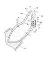
- FIG. 1is an exploded perspective view showing an orthodontic aligner and a mandible according to the first embodiment.
- FIG. 2is a cross-sectional view of an incisor showing a state in which the orthodontic aligner of Example 1 is attached to a tooth model at an orthodontic target position in three-dimensional data.
- FIG. 3is a cross-sectional view of a molar tooth showing a state in which the orthodontic aligner of Example 1 is attached to a tooth model at an orthodontic target position in three-dimensional data.
- the configuration of the orthodontic aligner of Example 1will be described.
- the tooth 10shows the one before orthodontics
- the tooth model 10Ashows the one at the orthodontic target position.
- the orthodontic aligner 20is formed by a laminated modeling device based on three-dimensional data created so as to be in close contact with the tooth model 10A at the orthodontic target position.
- the orthodontic aligner 20is attached to the tooth 10 before orthodontics, and corrects the tooth 10 to be corrected to the correction target position.
- the tooth 10has a crown composed of an occlusal portion 11, a buccal side surface 12, and a lingual side surface 13.
- the tooth 10is supported by the gingiva 15 surrounding the root of the tooth 10.
- the occlusal portion 11is the occlusal end of the upper and lower teeth, and in the incisor, it means the tip thereof, in the canine, it means the tip, and in the molar tooth, it means the tip of the occlusal surface.
- the tooth model 10Aincludes an occlusal portion model 11A corresponding to the occlusal portion 11, a buccal side model 12A corresponding to the buccal side surface 12, and a lingual side model corresponding to the lingual side surface 13. It is composed of 13A.
- one protrusion (attachment) 30is attached to each of the buccal side surface 12 of the incisor and the buccal side surface 12 of the molar tooth in order to adjust the magnitude and direction of the applied force.
- the protrusion 30is formed as, for example, a rectangular protrusion made of resin.
- the protrusion 30is preferably made of a material that is colorless and transparent, white, or has a color tone equivalent to that of the patient's cervical region.
- the shape of the protrusion 30may be formed, for example, into a rectangular or cross-shaped plate, or may be formed into a shape having a curved surface such as a hemisphere or a cone.
- a convex shapemay be formed on the protrusion 30, or burrs may be left on the protrusion 30.
- the protrusion 30keeps the geometrical tolerance as small as possible.
- the inclination of the plane forming the outer surface of the protrusion 30is preferably within 0.50 [mm], and 0. It is more preferably within 25 [mm], and even more preferably within 0.10 [mm].
- the protrusion 30has a curved surface such as a hemisphere or a cone, the contour of an arbitrary line on the curved surface forming the outer surface of the protrusion 30 is within 0.50 [mm]. It is preferably within 0.25 [mm], more preferably within 0.10 [mm], and even more preferably within 0.10 [mm].
- the protrusion 30is formed of a flat surface from the viewpoint of suppressing the orthodontic aligner 20 from falling off or slipping and efficiently applying a force.
- the protrusion 30can be a pyramid, a prism, a truncated cone, or a truncated cone.
- the root of the protrusion 30(the portion connected to the tooth surface) may be R-shaped and smoothly connected to the tooth surface.
- the protrusion 30is preferably a polygonal prism in which all the surfaces connected to the top surface are planes intersecting at right angles.
- the protrusion 30can be a triangular prism, a quadrangular prism (rectangular parallelepiped), a regular hexahedron (cube), or a hexagonal prism. It is more preferable that the protrusion 30 is a rectangle such as a rectangular parallelepiped or a cube.
- the corners and corners of the protrusion 30may be R chamfered, C chamfered, or not chamfered. However, from the viewpoint of making it less slippery and having excellent accuracy in transmitting the straightening force, it is preferable that the protrusion 30 is C-chamfered or not chamfered, and it is more preferable that the protrusion 30 is not chamfered. It is preferable that the edges are not chamfered and have sharp edges.
- the length of the shortest side 31 of the sides of the protrusion model 30Ais L1, and the radius of curvature of the corner 32 is R1. That is, the length of the shortest side 31 of the sides of the protrusion 30 is L1, and the radius of curvature of the corner 32 is R1.
- R1 / L1is preferably 0.5 or less, more preferably 0.2 or less, and even more preferably 0.1 or less.
- the protrusion 30may be hollow or may be filled inside.
- the protrusion 30may be formed only on a single tooth, or may be formed across a plurality of teeth.
- a method of attaching the protrusion 30for example, a method of adhering the protrusion 30 that has been molded in advance, or a method of using a template provided with a recess for forming the protrusion 30 and using a curable composition on the tooth surface of the patient. Examples thereof include a method of directly curing on the tooth surface and a method of forming directly on the tooth surface of a patient with a curable composition using an aligner to be treated.
- the designed shapecan be accurately reflected, and a force of an appropriate direction and magnitude can be applied (applied).
- a method of adhering the protruding portion 30 or a method of directly curing the protruding portion 30 on the tooth surface of the patient with a curable composition using a templateis preferable.
- Examples of the method of pre-molding the protrusion 30include laminated molding, cutting, injection molding, and cast molding. Of these, laminated molding or cutting is preferable from the viewpoint of reducing the geometrical tolerance of the recess, and laminated molding or cutting using CAD / CAM technology is more preferable.
- the above molding methodmay be used alone or in combination of two or more.
- the orthodontic aligner 20is formed in a concave groove shape at the occlusal portion 21, the buccal side portion 22, and the lingual side portion 23, and can be attached to and detached from the crown of the lower jaw. It has become. Further, the orthodontic aligner 20 is provided with two recesses 25 on the back surface of the buccal side portion 22.
- the occlusal portion 21is formed in a shape along the occlusal portion model 11A of the tooth model 10A. That is, the occlusal portion 21 is formed in a shape that covers the occlusal portion model 11A.
- the buccal side portion 22is formed in a shape along the buccal side portion model 12A of the tooth model 10A. That is, the buccal side portion 22 is formed in a shape that covers the buccal side portion model 12A.
- the lingual side portion 23is formed in a shape along the lingual side portion model 13A of the tooth model 10A. That is, the lingual side portion 23 is formed in a shape that covers the lingual side portion model 13A.
- the recess 25is formed in a shape that fits closely with the two protrusion models 30A attached to the tooth model 10A at the correction target position. That is, the recess 25 is formed in a rectangular concave shape corresponding to the protrusion model 30A.
- the recess 25keeps the geometrical tolerance as small as possible.
- the inclination of the plane forming the inner surface of the recess of the mouthpiece corresponding to the protrusion 30is within 0.50 [mm]. It is preferably within 0.25 [mm], more preferably within 0.10 [mm], and even more preferably within 0.10 [mm].
- the recess 25is a plane in which all the surfaces adjacent to the bottom surface intersect at right angles so as to correspond to this. It is preferable to have such a shape.
- the protrusion 30is formed in a rectangular shape, it is desirable that the recess 25 has a shape corresponding to this so that all adjacent planes intersect at right angles.
- the contour degree of an arbitrary line on the curved surface forming the inner surface of the concave portion of the mouthpiece corresponding to the protrusion 30is 0. It is preferably within .50 [mm], more preferably within 0.25 [mm], and even more preferably within 0.10 [mm].
- the corners and corners of the recess 25may be R chamfered, C chamfered, or not chamfered. However, from the viewpoint of making it less slippery and having excellent accuracy in propagating the straightening force, it is preferable that the corners and corners of the recess 25 are C-chamfered or not chamfered, and are not chamfered. It is more preferable, and it is more preferable that the edges are not chamfered and have sharp edges.
- the length of the shortest side 26 among the sides of the inner surface of the recess 25is L2, and the radius of curvature of the corner portion 27 is R2.
- R2 / L2is preferably 0.5 or less, more preferably 0.2 or less, and even more preferably 0.1 or less.
- the recess 25may have a shape that fits into a single protrusion 30, or may have a shape that fits into a plurality of protrusions 30.
- the orthodontic aligner 20is formed with a substantially uniform thickness as shown in FIGS. 2 and 3.
- the occlusal portion 21is formed with a thickness T1.
- the buccal side portion 22is formed with a thickness T1.
- the lingual side portion 23is formed with a thickness T1.
- the recess 25is formed with a thickness T1.
- the thickness T1is preferably 1.5 [mm] or less, more preferably 1.0 [mm] or less, and further preferably 0.8 [mm] or less. If the thickness exceeds 1.5 [mm], the risk of tooth subsidence increases as a side effect, and the wearing feeling may decrease.
- the difference in thicknessis preferably within 0.50 [mm], more preferably within 0.25 [mm], and even more preferably within 0.10 [mm].
- Examples of a method for manufacturing a mouthpiece having a recess corresponding to the protrusion 30include laminated molding, cutting, injection molding, cast molding and the like. Of these, from the viewpoint of reducing the geometrical tolerance of the concave portion of the mouthpiece, the method for manufacturing the mouthpiece is preferably laminated molding.
- the above molding methodmay be used alone or in combination of two or more.
- the orthodontic aligner 20 configured in this wayis attached to the tooth 10 of the mandible before orthodontics.
- the tooth 10 to which the orthodontic aligner 20 is attachedis corrected to the correction target position. At this time, the force applied by the protrusion 30 to the tooth 10 is finely adjusted.
- a plurality of orthodontic aligners 20are prepared, and the teeth 10 are stepwise corrected to the final orthodontic target position.
- One orthodontic aligner 20is formed in a shape that allows the teeth 10 to be moved and corrected by, for example, about 0.25 [mm].
- FIG. 4is a flowchart illustrating a method for manufacturing the orthodontic aligner 20 according to the first embodiment. Hereinafter, a method for manufacturing the orthodontic aligner 20 of Example 1 will be described.
- a three-dimensional scanneris used to scan the oral cavity of the patient to acquire three-dimensional data in the oral cavity.
- step S11the three-dimensional data in the oral cavity acquired in the oral data acquisition step is analyzed by a computer, and the three-dimensional data of the tooth model 10A at the correction target position is created.
- the three-dimensional data of the tooth model 10A of a plurality of correction target positionsis created.
- the protrusion model 30Ais appropriately attached depending on the direction of correction and the magnitude of the required force. From the viewpoint of reducing the burden on the patient, it is preferable to attach the protrusion model 30A so as not to change the position during a series of treatment plans as much as possible.
- the orthodontic aligner 20is based on the three-dimensional data of the tooth model 10A and the protrusion model 30A of the orthodontic target position created in the digital setup step. Create 3D data.
- Supportmay be added to the created three-dimensional data of the orthodontic aligner 20 as needed.
- the shape, thickness, density, angle, etc. of the supportare appropriately adjusted according to the size, angle, and overhang portion of the three-dimensional data.
- the orthodontic aligner 20is formed by the laminated modeling device based on the three-dimensional data of the orthodontic aligner 20 created in the three-dimensional data creation step of the orthodontic aligner 20. To manufacture.
- step S14In the post-treatment step (step S14), some or all unreacted substances, for example, unpolymerized monomers, are removed from the produced orthodontic aligner 20.
- the maximum gap between the orthodontic aligner 20 manufactured in this way and the three-dimensional data of the tooth model 10Acan be 0.25 mm or less.
- FIG. 5is a cross-sectional view of an incisor showing a state in which an orthodontic aligner of a comparative example is attached to a tooth model at an orthodontic target position.
- FIG. 6is a cross-sectional view of a molar tooth showing a state in which an orthodontic aligner of a comparative example is attached to a tooth model at an orthodontic target position.
- the operation of the orthodontic aligner 20 of Example 1 and the method for manufacturing the samewill be described with reference to FIGS. 5 and 6.
- the orthodontic aligner 520 of the comparative exampleis formed by pressing a thermoplastic resin sheet from above against the tooth model 510A in which the teeth are moved to the orthodontic target position.
- a gap G between the tooth model 510A and the orthodontic aligner 520is formed directly under the protrusion model 530A.
- the template provided with the recess for forming the protrusion 30is produced by press molding. Therefore, in such a template, the resin does not follow the lower portion of the protrusion 30 and the sharp edge portion provided on the tooth model.
- the protrusion 30 formed by the template produced by such a methodcannot reproduce the shape as designed in the lower portion of the protrusion 30 and the sharp edge portion, and the angular portion is reduced. Therefore, it may become slippery.
- the orthodontic aligner 20 of the first embodimentis an orthodontic aligner 20 that corrects the tooth to be corrected to the correction target position, and is an occlusal portion (occlusal part model) of the tooth model 10A at the correction target position.
- a recess 25formed in a shape that fits into a protrusion (protrusion model 30A) attached to the tooth model 10A (FIG. 2).
- the recess 25can be brought into close contact with the protrusion (protrusion model 30A) at the correction target position. Therefore, the gap between the orthodontic aligner 20 and the tooth model 10A at the orthodontic target position can be suppressed. As a result, the adhesion to the tooth 10 to be corrected can be improved, and the tooth 10 can be moved to the correction target position by applying an appropriate force. Therefore, the tooth 10 to be corrected can be corrected to a target position, for example, a position of a simulation result.
- the orthodontic aligner 20 of Example 1can accurately reflect the design of the operator. Therefore, the accuracy of the simulation before treatment can be improved.
- the orthodontic aligner 520 of the comparative exampleis molded by pressing a thermoplastic resin sheet from above against the tooth model 510A in which the teeth are moved to the orthodontic target position. Therefore, in the orthodontic aligner 520 of the comparative example, the buccal side portion 522 and the lingual side portion 523 are thinly stretched. Then, the thickness T2 of the buccal side portion 522 and the lingual side portion 523 becomes thinner than the thickness T3 of the occlusal portion 521. As a result, the tooth 10 may be pushed into the lower or upper gingiva, or the lateral (horizontal) orthodontic force of the tooth 10 may decrease. Therefore, the orthodontic aligner of the comparative example cannot correct the tooth 10 to the target position.
- the thickness T1 of the occlusal portion 21, the buccal side portion 22, and the lingual side portion 23is substantially uniform (FIG. 2).
- the tooth 10can be corrected to the target position.
- the orthodontic aligner 20includes a laminated modeling step manufactured by a laminated modeling device (FIG. 4).
- the gap between the orthodontic aligner 20 and the tooth model 10A at the orthodontic target positioncan be within 0.10 [mm]. .. Therefore, the tooth 10 to be corrected can be moved to the correction target position by applying an appropriate force. As a result, the tooth 10 to be corrected can be corrected to a target position.
- the stacking pitchis preferably 0.25 [mm] or less, more preferably 0.15 [mm] or less, and even more preferably 0.10 [mm] or less.
- the stacking pitchis preferably 0.01 [mm] or more, more preferably 0.02 [mm] or more, and even more preferably 0.05 [mm] or more.
- the stacking pitchexceeds 0.25 [mm]
- the stacking marks on the surface of the orthodontic alignermay be conspicuous, and the aesthetics and cleanability may be deteriorated.
- the stacking pitchis less than 0.01 [mm]
- the curingprogresses to the periphery of the designed area due to excessive laser light irradiation, the molding accuracy decreases, and the orthodontic aligner becomes thicker than the design. It ends up.
- the orthodontic aligner of Example 2is different from the orthodontic aligner of Example 1 in that the occlusal portion, the buccal side portion, and the lingual side portion are different in configuration.
- FIG. 7is a cross-sectional view of a molar tooth showing a state in which the orthodontic aligner of Example 2 is attached to a tooth model at an orthodontic target position in three-dimensional data.
- the configuration of the orthodontic aligner of Example 2will be described with reference to FIG. 7.
- the same or equivalent parts as those described in the above exampleswill be described using the same terms or the same reference numerals.
- the orthodontic aligner 120 of the second embodimentis formed in a concave groove shape by the occlusal portion 121, the buccal side portion 122, and the lingual side portion 123, and is attached to and detached from the lower jaw tooth model 10A. It is possible.
- the occlusal portion 121is formed with a thickness of T4.
- the buccal side portion 122is formed with a thickness T5 thicker than the thickness T4.
- the lingual side portion 123is formed with a thickness T8 thinner than the thickness T4.
- the lingual side portion 123can be made thicker than the thickness T4.
- the horizontal thickness T6 of the side portion 122b forming the recess 25is formed to be thicker than the thickness T4.
- the surface of the buccal side portion 122 corresponding to the recess 25is formed in a smooth shape without steps.
- the minimum thickness T7 of the lower portion 122a forming the recess 25is set to be equal to or greater than the horizontal thickness T6 of the side portion 122b forming the recess 25.
- the relationship between the minimum thickness T7 of the lower portion 122a forming the concave portion 25 and the horizontal thickness T6 of the side portion 122b forming the concave portion 25satisfies the following relational expression. T7 / T6 ⁇ 1
- the thickness T5 of at least one of the buccal side portion 122 and the lingual side portion 123is thicker than the thickness T4 of the occlusal portion 121 (FIG. 7).
- the thickness T4 of the occlusal portion 521can be reduced, it is possible to prevent the tooth 10 from being unintentionally pushed into the lower or upper gingiva. Further, since the thickness T5 of at least one of the buccal side portion 122 and the lingual side portion 123 can be increased, the lateral (horizontal) corrective force of the tooth 10 can be improved.
- the orthodontic aligner 120when the orthodontic aligner 120 is placed in the oral cavity, the feeling of foreign matter disappears. As a result, the wearing feeling of the orthodontic aligner 120 can be improved.
- the minimum thickness T7 of the lower portion 122a forming the concave portion 25is equal to or larger than the horizontal thickness T6 of the side portion 122b forming the concave portion 25 (FIG. 7).
- the lower surface of the recess 25can be brought into close contact with the protrusion 30, and the straightening force can be improved.
- Example 1 and Example 2two protrusions 30 are attached to the buccal side surface 12.
- the place and number of protrusions to be attachedare not limited to this embodiment.
- the protrusionmay be attached to the buccal side 22 or the lingual side 23.
- the protrusion 30is formed in a rectangular shape.
- the protrusionis not limited to a rectangle, and may be formed in a hemispherical shape, a conical shape, or a cross shape, for example.
- the additive manufacturing devicemay be a projection method in which the photocurable resin is cured by using the light of a projector and laminated, or a liquid ultraviolet curable resin is jetted and cured by illuminating the ultraviolet rays. It may be an inkjet method in which heat-soluble resins are laminated one by one, or a heat-melting lamination method in which heat-soluble resins are stacked one by one, or powder baking in which a powdery material is sintered by applying a high-power laser beam. It may be a connection method.
- the orthodontic aligners 20 and 120are formed in a concave groove shape covering the crown (occlusal portion 11, buccal side surface 12, and lingual side surface 13).
- the orthodontic alignermay have a shape that covers the crown and the gingiva, or the crown and the floor portion.
- Example 1 and Example 2an example in which the present invention is applied to the orthodontic aligners 20 and 120 to be attached to the crown of the lower jaw is shown. However, the present invention can be applied to an orthodontic aligner to be attached to the crown of the maxilla.
Landscapes
- Health & Medical Sciences (AREA)
- Oral & Maxillofacial Surgery (AREA)
- Dentistry (AREA)
- Epidemiology (AREA)
- Life Sciences & Earth Sciences (AREA)
- Animal Behavior & Ethology (AREA)
- General Health & Medical Sciences (AREA)
- Public Health (AREA)
- Veterinary Medicine (AREA)
- Dental Tools And Instruments Or Auxiliary Dental Instruments (AREA)
Abstract
Description
Translated fromJapanese本発明は、歯列矯正用アライナー及びその製造方法に関するものである。The present invention relates to an orthodontic aligner and a method for manufacturing the same.
歯列矯正用アライナーは、板状の樹脂シートをプレス加工することで形成される(例えば、特許文献1参照)。The orthodontic aligner is formed by pressing a plate-shaped resin sheet (see, for example, Patent Document 1).
特許文献1には、歯の型の模型を用いて、未硬化の樹脂の薄板を与圧型抜き装置などによりプレスして硬化することで、歯列矯正用アライナーが形成される構成が開示されている。Patent Document 1 discloses a configuration in which an orthodontic aligner is formed by pressing an uncured resin thin plate with a pressure die punching device or the like to cure it using a tooth mold model. There is.
しかしながら、特許文献1に記載の構成では、矯正力の大きさや方向を調整することを目的に歯に突起部を取り付ける場合、プレス成形時に歯の型の模型に付与された突起部の下部に樹脂が追随せず、歯列矯正用アライナーと歯の型の模型との間に間隙が形成されてしまう。However, in the configuration described in Patent Document 1, when a protrusion is attached to a tooth for the purpose of adjusting the magnitude and direction of the orthodontic force, a resin is applied to the lower portion of the protrusion given to the tooth mold model during press molding. Does not follow, and a gap is formed between the orthodontic aligner and the tooth mold model.
そのため、歯列矯正用アライナーを突起部が取り付けられた実際の歯に装着した際、当然ながら上記間隙は、歯列矯正用アライナーと矯正前後の歯に取り付けられた突起部との間にも生じてしまう。Therefore, when the orthodontic aligner is attached to the actual tooth to which the protrusion is attached, the above gap naturally occurs between the orthodontic aligner and the protrusion attached to the tooth before and after the orthodontic treatment. It ends up.
また、歯列矯正用アライナーによる歯の矯正によって、突起部も移動すると、歯列矯正用アライナーと、矯正後の歯や矯正後の歯に取り付けられた突起部との間の間隙が大きくなる。In addition, when the protrusions are also moved by the correction of the teeth by the orthodontic aligner, the gap between the orthodontic aligner and the protrusions attached to the orthodontic tooth or the orthodontic tooth becomes large.
このとき、歯列矯正用アライナーは、突起部や歯への密着性が低下するため、突起部に力を伝播させにくくなり、適正な矯正力を発揮することができないという問題が生じる。At this time, since the orthodontic aligner has reduced adhesion to the protrusions and teeth, it becomes difficult to propagate the force to the protrusions, and there arises a problem that an appropriate orthodontic force cannot be exerted.
また、樹脂の物性及び歯列矯正用アライナーの構造をデータとして入力し、CAE(Computer Aided Engineering)解析などの手法に基づいたシミュレーションソフトを利用することで、歯に与える矯正力及び治療過程をシミュレートできる場合がある。しかしながら、特許文献1に記載の構成では、デザインした歯列矯正用アライナーと、実際に製造される歯列矯正用アライナーとの間に構造的な差異が生じるため、シミュレーション結果の精度が低下することも考えられる。In addition, by inputting the physical properties of the resin and the structure of the orthodontic aligner as data and using simulation software based on methods such as CAE (Computer Aided Engineering) analysis, the orthodontic force applied to the teeth and the treatment process are simulated. You may be able to do it. However, in the configuration described in Patent Document 1, the accuracy of the simulation result is lowered because a structural difference occurs between the designed orthodontic aligner and the actually manufactured orthodontic aligner. Is also possible.
そこで、本発明は、歯列矯正用アライナーと歯や突起部との間隙を抑制した歯列矯正用アライナーを提供することを目的とする。Therefore, an object of the present invention is to provide an orthodontic aligner in which the gap between the orthodontic aligner and the teeth or protrusions is suppressed.
前記目的を達成するために、本発明の歯列矯正用アライナーは、矯正対象となる歯を矯正目標位置に矯正する歯列矯正用アライナーであって、前記矯正目標位置の歯モデルの咬合部分を覆う咬合部と、前記歯モデルの頬側面を覆う頬側部と、前記歯モデルの舌側面を覆う舌側部と、前記歯モデルに取り付けられた突起部に嵌る形状に形成される凹部と、を備えることを特徴とする。In order to achieve the above object, the orthodontic aligner of the present invention is an orthodontic aligner that corrects the tooth to be corrected to the correction target position, and the occlusal portion of the tooth model at the correction target position is formed. An occlusal portion to cover, a buccal side portion covering the buccal side surface of the tooth model, a lingual side portion covering the lingual side surface of the tooth model, and a recess formed in a shape that fits into a protrusion attached to the tooth model. It is characterized by having.
このように構成された本発明の歯列矯正用アライナー及びその製造方法は、歯列矯正用アライナーと歯に取り付けられた突起部との間隙の抑制により、効率よく突起部に力を伝播させることができ、適正な矯正力を発揮することができる。The orthodontic aligner and the manufacturing method thereof of the present invention configured in this way efficiently propagate the force to the protrusions by suppressing the gap between the orthodontic aligner and the protrusions attached to the teeth. And can exert proper corrective power.
以下、本発明による歯列矯正用アライナー及びその製造方法を実現する実施形態を、図面に示す実施例1及び実施例2に基づいて説明する。Hereinafter, embodiments for realizing an orthodontic aligner and a method for manufacturing the same according to the present invention will be described with reference to Examples 1 and 2 shown in the drawings.
実施例1における歯列矯正用アライナーは、下顎の歯冠に装着される歯列矯正用アライナーに適用される。The orthodontic aligner in Example 1 is applied to the orthodontic aligner attached to the crown of the lower jaw.
[歯列矯正用アライナーの構成]
図1は、実施例1の歯列矯正用アライナーと下顎を示す分解斜視図である。図2は、実施例1の歯列矯正用アライナーを、3次元データにおいて、矯正目標位置の歯モデルに装着した状態を示す切歯の断面図である。図3は、実施例1の歯列矯正用アライナーを、3次元データにおいて、矯正目標位置の歯モデルに装着した状態を示す臼歯の断面図である。以下、実施例1の歯列矯正用アライナーの構成を説明する。なお、図1~図3において、歯10は矯正前のものを示し、歯モデル10Aは矯正目標位置のものを示す。[Composition of orthodontic aligner]
FIG. 1 is an exploded perspective view showing an orthodontic aligner and a mandible according to the first embodiment. FIG. 2 is a cross-sectional view of an incisor showing a state in which the orthodontic aligner of Example 1 is attached to a tooth model at an orthodontic target position in three-dimensional data. FIG. 3 is a cross-sectional view of a molar tooth showing a state in which the orthodontic aligner of Example 1 is attached to a tooth model at an orthodontic target position in three-dimensional data. Hereinafter, the configuration of the orthodontic aligner of Example 1 will be described. In FIGS. 1 to 3, the
歯列矯正用アライナー20は、図2に示すように、矯正目標位置の歯モデル10Aに密着するように作成された3次元データに基づいて、積層造形装置によって形成される。歯列矯正用アライナー20は、矯正前の歯10に装着されて、矯正対象となる歯10を矯正目標位置に矯正する。As shown in FIG. 2, the
(歯の構成)
歯10は、図1に示すように、咬合部分11と、頬側面12と、舌側面13と、で構成される歯冠を有する。歯10は、歯10の根元を取り巻く歯肉15によって支持される。(Tooth composition)
As shown in FIG. 1, the
咬合部分11とは、上下の歯の咬み合い側の端部であり、切歯においては、その先端のことをいい、犬歯においては、その先端のことをいい、臼歯においては、その咬合面のことをいう。The
(歯モデルの構成)
歯モデル10Aは、図2及び図3に示すように、咬合部分11に対応する咬合部分モデル11Aと、頬側面12に対応する頬側部モデル12Aと、舌側面13に対応する舌側部モデル13Aと、で構成される。(Composition of tooth model)
As shown in FIGS. 2 and 3, the
切歯の頬側面12と臼歯の頬側面12には、かかる力の大きさや向きを調整するため、図1に示すように、それぞれ1つの突起部(アタッチメント)30が取り付けられる。突起部30は、例えば、樹脂製の矩形の突起として形成される。突起部30は、好ましくは、無色透明、白色又は患者当人の歯頚と同等の色調を有する材料で形成される。As shown in FIG. 1, one protrusion (attachment) 30 is attached to each of the
突起部30の形状は、例えば、矩形や十字状の板状に形成されても、半球状や円錐状のような曲面を有する形状に形成されてもよい。突起部30と歯列矯正用アライナー20の間の滑りを抑制する目的から、突起部30に凸形状が形成されていてもよいし、突起部30にバリが残されていてもよい。The shape of the
突起部30は、可能な限り小さい幾何公差を守っていることがより好ましい。突起部30が、例えば、矩形や十字状の板状に形成される場合、突起部30の外表面を構成する平面の傾斜度は、0.50[mm]以内であることが好ましく、0.25[mm]以内であることがより好ましく、0.10[mm]以内であることがさらに好ましい。突起部30が、例えば半球状や円錐状のような曲面を有する形状の場合には、突起部30の外表面を構成する曲面における任意の線の輪郭度は、0.50[mm]以内であることが好ましく、0.25[mm]以内であることがより好ましく、0.10[mm]以内であることがさらに好ましい。It is more preferable that the
突起部30は、歯列矯正用アライナー20の脱落や滑りを抑制して効率的に力を付与することができるという観点から、少なくとも一部が平面で構成されていることが好ましい。例えば、突起部30は、角錐、多角柱、角錐台、円錐台とすることができる。なお、突起部30の根本(歯面に接続する部分)は、R状にして、歯面に滑らかに接続してもよい。It is preferable that at least a part of the
突起部30は、天面に接続する全ての面が、直角に交わる平面となる多角柱とすることが好ましい。例えば、突起部30は、三角柱、四角柱(直方体)、正六面体(立方体)、六角柱とすることができる。突起部30は、直方体、立方体などの矩形とすることがさらに好ましい。
The
突起部30の角部、隅部はR面取りされていてもよく、C面取りされていてもよく、面取りされていなくてもよい。ただし、滑りにくくして矯正力を伝播する正確性に優れたものにする観点から、突起部30は、C面取りされている、若しくは、面取りされていない方が好ましく、面取りされていない方がより好ましく、面取りされておらず鋭利なエッジを形成している方がさらに好ましい。The corners and corners of the
例えば、図2に示すように、突起部モデル30Aの辺のうち、最も短い辺31の長さをL1とし、角部32の曲率半径をR1とする。すなわち、突起部30の辺のうち、最も短い辺31の長さをL1とし、角部32の曲率半径をR1とする。この場合、R1/L1は、0.5以下であることが好ましく、0.2以下であることがより好ましく、0.1以下であることがさらに好ましい。For example, as shown in FIG. 2, the length of the
突起部30は、中空であってもよく、内部が充填されていてもよい。突起部30は、単独の歯のみに形成されても良く、複数の歯に跨って形成されてもよい。The
突起部30を取り付ける方法としては、例えば、予め成形加工された突起部30を接着する方法や、突起部30を形成するための凹部を備えたテンプレートを用いて硬化性組成物により患者の歯面上で直接硬化させる方法や、治療に供するアライナーを用いて硬化性組成物により患者の歯面上に直接形成する方法などが挙げられる。As a method of attaching the
特に、矯正前の歯に対して正確に配置でき、デザインされた形状を正確に反映して、適正な方向及び大きさの力を付与(印加)することができるという観点から、予め成形加工された突起部30を接着する方法、若しくは、テンプレートを用いて硬化性組成物により患者の歯面上で直接硬化させる方法が好ましい。予め成形加工された突起部30を接着する場合には、突起部30を設置するための凹部を備えたインダイレクトボンディングトレーを用いて正確に配置し、接着することが好ましい。In particular, it is preformed from the viewpoint that it can be accurately placed on the tooth before orthodontics, the designed shape can be accurately reflected, and a force of an appropriate direction and magnitude can be applied (applied). A method of adhering the protruding
突起部30を予め成形加工する方法としては、例えば積層造形や、切削加工や、射出成形や、キャスト成形などが挙げられる。このうち、凹部の幾何公差を小さくする観点からは積層造形又は切削加工が好ましく、積層造形やCAD/CAM技術を用いた切削加工がさらに好ましい。上記の成形加工方法は、単独で使用されても良く、複数を組み合わせても良い。Examples of the method of pre-molding the
(歯列矯正用アライナーの構成)
歯列矯正用アライナー20は、図1~図3に示すように、咬合部21と、頬側部22と、舌側部23とで凹溝状に形成され、下顎の歯冠に脱着可能になっている。また、歯列矯正用アライナー20は、頬側部22の裏面に2つの凹部25を備える。(Composition of orthodontic aligner)
As shown in FIGS. 1 to 3, the
咬合部21は、図2及び図3に示すように、歯モデル10Aの咬合部分モデル11Aに沿った形状に形成される。すなわち、咬合部21は、咬合部分モデル11Aを覆う形状に形成される。As shown in FIGS. 2 and 3, the
頬側部22は、歯モデル10Aの頬側部モデル12Aに沿った形状に形成される。すなわち、頬側部22は、頬側部モデル12Aを覆う形状に形成される。The
舌側部23は、歯モデル10Aの舌側部モデル13Aに沿った形状に形成される。すなわち、舌側部23は、舌側部モデル13Aを覆う形状に形成される。The
凹部25は、矯正目標位置の歯モデル10Aに取り付けられた2つの突起部モデル30Aに密着して嵌る形状に形成される。すなわち、凹部25は、突起部モデル30Aに対応して、矩形の凹状に形成される。The
凹部25は、可能な限り小さい幾何公差を守っていることがより好ましい。突起部30が、例えば矩形や十字状の板状に形成される場合には、突起部30に対応するマウスピーの凹部の内表面を構成する平面の傾斜度は、0.50[mm]以内であることが好ましく、0.25[mm]以内であることがより好ましく、0.10[mm]以内であることがさらに好ましい。It is more preferable that the
突起部30が、天面に接続する面が全て直角に交わる平面となる多角柱とする場合、凹部25は、これに対応するように、底面に隣接する全ての面が直角に交わる平面となるような形状にすることが好ましい。突起部30が矩形に形成される場合、凹部25は、これに対応するように、隣接する全ての平面が直角に交わるような形状にすることが望ましい。When the
突起部30が、例えば半球状や円錐状のような曲面で構成される形状の場合、突起部30に対応するマウスピースの凹部の内表面を構成する曲面における任意の線の輪郭度は、0.50[mm]以内であることが好ましく、0.25[mm]以内であることがより好ましく、0.10[mm]以内であることがさらに好ましい。When the
凹部25の角部や隅部は、R面取りされていてもよく、C面取りされていてもよく、面取りされていなくてもよい。ただし、滑りにくくして矯正力を伝播する正確性に優れたものにする観点から、凹部25の角部や隅部は、C面取りされているか、面取りされていない方が好ましく、面取りされていない方がより好ましく、面取りされておらず鋭利なエッジを形成している方がさらに好ましい。The corners and corners of the
例えば、図2に示すように、凹部25の内表面の辺のうち、最も短い辺26の長さをL2、角部27の曲率半径をR2とする。この場合、R2/L2は0.5以下であることが好ましく、0.2以下であることがより好ましく、0.1以下であることがさらに好ましい。For example, as shown in FIG. 2, the length of the
凹部25は、単一の突起部30に嵌る形状でもよいし、複数の突起部30に嵌る形状でもよい。The
歯列矯正用アライナー20は、図2及び図3に示すように、略均一な厚みで形成される。咬合部21は、厚みT1で形成される。頬側部22は、厚みT1で形成される。舌側部23は、厚みT1で形成される。凹部25は、厚みT1で形成される。なお、厚みT1は、1.5[mm]以下であることが好ましく、1.0[mm]以下であることがより好ましく、0.8[mm]以下であることがさらに好ましい。厚みが1.5[mm]を上回ると、副作用として歯の沈下のリスクが高くなり、装着感も低下することがある。厚みの差は、0.50[mm]以内であることが好ましく、0.25[mm]以内であることがより好ましく、0.10[mm]以内であることがさらに好ましい。The
突起部30に対応する凹部を備えるマウスピースを製造する方法としては、例えば積層造形、切削加工、射出成形、キャスト成形などが挙げられる。このうち、マウスピースの凹部の幾何公差を小さくする観点から、マウスピースを製造する方法は、積層造形が好ましい。上記の成形加工方法は、単独で使用されても良く、複数を組み合わせても良い。Examples of a method for manufacturing a mouthpiece having a recess corresponding to the
このように構成された歯列矯正用アライナー20は、下顎の矯正前の歯10に装着される。歯列矯正用アライナー20が装着された歯10は、矯正目標位置に矯正される。この際、突起部30が歯10に対して加える力を細かく調整する。The
歯列矯正用アライナー20は、複数用意され、歯10を段階的に、最終矯正目標位置に矯正する。1つの歯列矯正用アライナー20は、例えば、0.25[mm]ほど歯10を移動して矯正することができる形状に形成される。A plurality of
[歯列矯正用アライナーの製造方法]
図4は、実施例1の歯列矯正用アライナー20の製造方法を説明するフローチャートである。以下、実施例1の歯列矯正用アライナー20の製造方法を説明する。[Manufacturing method of orthodontic aligner]
FIG. 4 is a flowchart illustrating a method for manufacturing the
(口腔内データ取得工程)
口腔内データ取得工程(ステップS10)では、3次元スキャナーを用いて、患者の口腔内をスキャンして、口腔内の3次元データを取得する。(Intraoral data acquisition process)
In the intraoral data acquisition step (step S10), a three-dimensional scanner is used to scan the oral cavity of the patient to acquire three-dimensional data in the oral cavity.
(デジタルセットアップ工程)
デジタルセットアップ工程(ステップS11)では、口腔内データ取得工程で取得した口腔内の3次元データをコンピュータで解析し、矯正目標位置の歯モデル10Aの3次元データを作成する。例えば、0.25[mm]刻みのように、段階的に最終矯正目標位置に矯正する場合は、複数の矯正目標位置の歯モデル10Aの3次元データを作成する。矯正の方向や必要な力の大きさによって、突起部モデル30Aを適宜取り付ける。患者の負担軽減の観点から、可能な限り一連の治療計画中に突起部モデル30Aの位置変更がないように取り付けることが好ましい。(Digital setup process)
In the digital setup step (step S11), the three-dimensional data in the oral cavity acquired in the oral data acquisition step is analyzed by a computer, and the three-dimensional data of the
このとき、CAE(Computer Aided Engineering)解析などの手法に基づくシミュレーションソフトや、ビッグデータを用いた機械学習に基づくシミュレーションソフトを利用し、歯に与える矯正力及び治療過程をシミュレートしながら段階的に複数の矯正目標位置の歯モデル10Aの3次元データを作成してもよい。At this time, using simulation software based on methods such as CAE (Computer Aided Engineering) analysis and simulation software based on machine learning using big data, step by step while simulating the orthodontic force applied to the teeth and the treatment process. Three-dimensional data of the
(歯列矯正用アライナーの3次元データ作成工程)
歯列矯正用アライナーの3次元データ作成工程(ステップS12)では、デジタルセットアップ工程で作成した矯正目標位置の歯モデル10A及び突起部モデル30Aの3次元データに基づいて、歯列矯正用アライナー20の3次元データを作成する。(3D data creation process for orthodontic aligners)
In the three-dimensional data creation step (step S12) of the orthodontic aligner, the
作成された歯列矯正用アライナー20の3次元データには、必要に応じてサポートを付与してよい。サポートの形状や太さ、密度、角度等は、3次元データの大きさ、角度、オーバーハング部に応じて適宜調整される。Support may be added to the created three-dimensional data of the
(積層造形工程)
積層造形工程(ステップS13)では、歯列矯正用アライナー20の3次元データ作成工程で作成した歯列矯正用アライナー20の3次元データに基づいて、積層造形装置によって、歯列矯正用アライナー20を製造する。(Laminate molding process)
In the laminated modeling step (step S13), the
(後処理工程)
後処理工程(ステップS14)では、製造された歯列矯正用アライナー20から一部あるいは全部の未反応物、例えば未重合の単量体を除去する。なお、後処理工程には、重力や遠心力を利用した未反応物の除去、有機溶剤による洗浄やエアブローによる未反応物の除去、乾燥、蛍光灯、ハロゲンランプ、LED光源などを用いた照射器による光重合や熱重合を施す工程を含んでもよい。以上の工程を経て、歯列矯正用アライナー20が製造される。(Post-treatment process)
In the post-treatment step (step S14), some or all unreacted substances, for example, unpolymerized monomers, are removed from the produced
このように製造された歯列矯正用アライナー20と、歯モデル10Aの3次元データとの最大間隙は、0.25mm以内とすることができる。The maximum gap between the
[歯列矯正用アライナー及びその製造方法の作用]
図5は、比較例の歯列矯正用アライナーを矯正目標位置の歯模型に装着した状態を示す切歯の断面図である。図6は、比較例の歯列矯正用アライナーを矯正目標位置の歯模型に装着した状態を示す臼歯の断面図である。以下、図5及び図6を参照して、実施例1の歯列矯正用アライナー20及びその製造方法の作用を説明する。[Action of orthodontic aligner and its manufacturing method]
FIG. 5 is a cross-sectional view of an incisor showing a state in which an orthodontic aligner of a comparative example is attached to a tooth model at an orthodontic target position. FIG. 6 is a cross-sectional view of a molar tooth showing a state in which an orthodontic aligner of a comparative example is attached to a tooth model at an orthodontic target position. Hereinafter, the operation of the
ところで、比較例の歯列矯正用アライナー520は、図5に示すように、矯正目標位置に歯を移動した歯模型510Aに、熱可塑性の樹脂シートを上方から押し当てて成形する。このようにして成形された比較例の歯列矯正用アライナー520は、突起模型530Aの直下に、歯模型510Aと歯列矯正用アライナー520との間隙Gが形成されてしまう。By the way, as shown in FIG. 5, the
また、突起部30を形成するための凹部を備えたテンプレートは、プレス成形によって作製される。そのため、このようなテンプレートは、歯の型の模型に付与された突起部30の下部や、鋭利なエッジの部分に樹脂が追随しない。Further, the template provided with the recess for forming the
そのため、このような方法で作製されたテンプレートによって形成される突起部30は、突起部30の下部や鋭利なエッジの部分において、デザインされた通りの形状を再現できず、角張った部分が少なくなるため、滑りやすくなってしまう場合がある。Therefore, the
このとき、突起部30や歯への密着性が低下するため、突起部30に力を伝播させにくくなり、適正な矯正力を発揮することができないという問題がある。At this time, since the adhesion to the
一方、実施例1の歯列矯正用アライナー20は、矯正対象となる歯を矯正目標位置に矯正する歯列矯正用アライナー20であって、矯正目標位置の歯モデル10Aの咬合部分(咬合部分モデル11A)を覆う咬合部21と、歯モデル10Aの頬側面(頬側部モデル12A)を覆う頬側部22と、歯モデル10Aの舌側面(舌側部モデル13A)を覆う舌側部23と、歯モデル10Aに取り付けられた突起部(突起部モデル30A)に嵌る形状に形成される凹部25と、を備える(図2)。On the other hand, the
これにより、凹部25を、矯正目標位置の突起部(突起部モデル30A)に密着させることができる。そのため、歯列矯正用アライナー20と矯正目標位置の歯モデル10Aとの間の隙間を抑制することができる。その結果、矯正対象の歯10に対する密着性も向上させることができ、矯正目標位置まで、適切な力を加えて移動させることができる。そのため、矯正対象の歯10を狙いの位置、例えばシミュレーション結果の位置に矯正することができる。As a result, the
また、実施例1の歯列矯正用アライナー20は、術者のデザインを正確に反映することができる。そのため、治療前のシミュレーションの精度を向上させることができる。Further, the
ところで、比較例の歯列矯正用アライナー520は、図6に示すように、矯正目標位置に歯を移動した歯模型510Aに、熱可塑性の樹脂シートを上方から押し当てて、成形する。そのため、比較例の歯列矯正用アライナー520は、頬側部522と舌側部523は、薄く延ばされてしまう。そして、頬側部522と舌側部523の厚みT2は、咬合部521の厚みT3より薄くなってしまう。その結果、歯10を下方又は上方の歯肉に押し込んでしまったり、歯10の横方向(水平方向)の矯正力が低下してしまったりする。そのため、比較例の歯列矯正用アライナーは、歯10を狙いの位置に矯正することができない。By the way, as shown in FIG. 6, the
一方、実施例1の歯列矯正用アライナー20では、咬合部21と、頬側部22と、舌側部23との厚みT1は、略均一である(図2)。On the other hand, in the
これにより、歯10を下方又は上方の歯肉に押し込んでしまうことを抑制して、歯10の横方向(水平方向)の矯正力を向上させることができる。そのため、歯10を狙いの位置に矯正することができる。As a result, it is possible to suppress pushing the
実施例1の歯列矯正用アライナー20の製造方法において、歯列矯正用アライナー20は、積層造形装置によって製造される積層造形工程を含む(図4)。In the method for manufacturing the
例えば、積層造形装置の積層ピッチを、0.10[mm]とした場合、歯列矯正用アライナー20と矯正目標位置の歯モデル10Aとの間隙を0.10[mm]以内とすることがきる。そのため、矯正対象の歯10を矯正目標位置まで、適切な力を加えて移動させることができる。その結果、矯正対象の歯10を狙いの位置に矯正することができる。For example, when the lamination pitch of the lamination molding apparatus is 0.10 [mm], the gap between the
なお、積層ピッチは、0.25[mm]以下が好ましく、0.15[mm]以下がより好ましく、0.10[mm]以下がさらに好ましい。また、積層ピッチは、0.01[mm]以上が好ましく、0.02[mm]以上がより好ましく、0.05[mm]以上がさらに好ましい。積層ピッチが0.25[mm]を超える場合、歯列矯正用アライナーの表面の積層痕が目立ち、審美性、清掃性が低下することがある。積層ピッチが0.01[mm]未満の場合、過剰なレーザー光の照射によりデザインされた領域の周辺まで硬化が進行して造形精度が低下し、歯列矯正用アライナーがデザインよりも厚くなってしまう。また、積層回数が増えることでエネルギーを受ける回数が増えるため、造形に使用するトレーが損傷しやすくなる。特に、トレーにシリコーンを使用している場合には、一度の造形で著しく劣化するため、同一の場所で2回以上の造形が不可能になる。これによりインク(例えば、光硬化性樹脂)を移す手間やロスが生じ、生産性が低下する。The stacking pitch is preferably 0.25 [mm] or less, more preferably 0.15 [mm] or less, and even more preferably 0.10 [mm] or less. The stacking pitch is preferably 0.01 [mm] or more, more preferably 0.02 [mm] or more, and even more preferably 0.05 [mm] or more. When the stacking pitch exceeds 0.25 [mm], the stacking marks on the surface of the orthodontic aligner may be conspicuous, and the aesthetics and cleanability may be deteriorated. If the stacking pitch is less than 0.01 [mm], the curing progresses to the periphery of the designed area due to excessive laser light irradiation, the molding accuracy decreases, and the orthodontic aligner becomes thicker than the design. It ends up. In addition, as the number of stacking increases, the number of times energy is received increases, so that the tray used for modeling is easily damaged. In particular, when silicone is used for the tray, it is remarkably deteriorated by one molding, so that it is impossible to mold more than once in the same place. As a result, it takes time and loss to transfer the ink (for example, a photocurable resin), and the productivity is lowered.
実施例2の歯列矯正用アライナーは、咬合部と、頬側部と、舌側部との構成が異なる点で、実施例1の歯列矯正用アライナーと相違する。The orthodontic aligner of Example 2 is different from the orthodontic aligner of Example 1 in that the occlusal portion, the buccal side portion, and the lingual side portion are different in configuration.
[歯列矯正用アライナーの構成]
図7は、実施例2の歯列矯正用アライナーを、3次元データにおいて、矯正目標位置の歯モデルに装着した状態を示す臼歯の断面図である。以下、図7に基づいて、実施例2の歯列矯正用アライナーの構成を説明する。なお、上記実施例で説明した内容と同一乃至均等な部分の説明については、同一の用語又は同一の符号を用いて説明する。[Composition of orthodontic aligner]
FIG. 7 is a cross-sectional view of a molar tooth showing a state in which the orthodontic aligner of Example 2 is attached to a tooth model at an orthodontic target position in three-dimensional data. Hereinafter, the configuration of the orthodontic aligner of Example 2 will be described with reference to FIG. 7. The same or equivalent parts as those described in the above examples will be described using the same terms or the same reference numerals.
実施例2の歯列矯正用アライナー120は、図7に示すように、咬合部121と、頬側部122と、舌側部123とで凹溝状に形成され、下顎の歯モデル10Aに脱着可能になっている。As shown in FIG. 7, the
咬合部121は、厚みT4で形成される。頬側部122は、厚みT4より厚い厚みT5で形成される。舌側部123は、厚みT4より薄い厚みT8で形成される。なお、舌側部123は、厚みT4より厚くすることもできる。The
頬側部122のうち、凹部25を形成する側部122bの水平方向の厚みT6は、厚みT4より厚く形成される。凹部25に対応する、頬側部122の表面は、段差のない滑らかな形状に形成される。Of the
頬側部122のうち、凹部25を形成する下部122aの最小厚みT7は、凹部25を形成する側部122bの水平方向の厚みT6以上とする。言い換えると、凹部25を形成する下部122aの最小厚みT7と、凹部25を形成する側部122bの水平方向の厚みT6との関係は、以下の関係式を満たす。
T7/T6≧1Of the
T7 / T6 ≧ 1
[歯列矯正用アライナーの作用]
実施例2の歯列矯正用アライナー120の作用を説明する。実施例2の歯列矯正用アライナー120において、頬側部122と舌側部123の少なくとも一方の厚みT5は、咬合部121の厚みT4より厚い(図7)。[Action of orthodontic aligner]
The operation of the
咬合部521の厚みT4を薄くすることができるので、意図せずに、歯10を下方又は上方の歯肉に押し込んでしまうことを防止することができる。また、頬側部122と舌側部123の少なくとも一方の厚みT5を厚くすることができるので、歯10の横方向(水平方向)の矯正力を向上させることができる。Since the thickness T4 of the
実施例2の歯列矯正用アライナー120において、凹部25に対応する表面は、滑らかに形成される(図7)。In the
これにより、歯列矯正用アライナー120を口腔内に装着した際に、異物感がなくなる。その結果、歯列矯正用アライナー120の装着感を向上させることができる。As a result, when the
実施例2の歯列矯正用アライナー120において、凹部25を形成する下部122aの最小厚みT7が、凹部25を形成する側部122bの水平方向の厚みT6以上である(図7)。In the
これにより、凹部25の下面を突起部30に密着させて、矯正力を向上させることができる。As a result, the lower surface of the
なお、他の構成及び作用効果については、上記実施例と略同様であるので説明を省略する。The other configurations and actions and effects are substantially the same as those in the above embodiment, and thus description thereof will be omitted.
以上、本発明の歯列矯正用アライナー及びその製造方法を実施例1及び実施例2に基づき説明してきた。しかし、具体的な構成については、これらの実施例に限られるものではなく、請求の範囲の各請求項に係る発明の要旨を逸脱しない限り、設計の変更や、各実施例の組み合わせや、追加等は許容される。The orthodontic aligner of the present invention and its manufacturing method have been described above based on Examples 1 and 2. However, the specific configuration is not limited to these examples, and as long as the gist of the invention according to each claim of the claims is not deviated, design changes, combinations of each embodiment, and additions are made. Etc. are acceptable.
実施例1及び実施例2では、突起部30が頬側面12に2つ取り付けられる例を示した。しかし、突起部としては、取り付けられる場所や個数は、この態様に限定されるものではない。例えば、突起部は、頬側部22や舌側部23に取り付けられてもよい。In Example 1 and Example 2, two
実施例1及び実施例2では、突起部30は、矩形に形成される例を示した。しかし、突起部としては、矩形に限定されず、例えば、半球状や、円錐状や、十字状に形成されてもよい。In Example 1 and Example 2, the
実施例1及び実施例2では、積層造形装置を、紫外線によって硬化する光硬化樹脂を使用した光造形方式とする例を示した。しかし、積層造形装置としては、プロジェクターの光を利用して光硬化樹脂を硬化させ積層していくプロジェクション方式であってもよいし、液状の紫外線硬化樹脂を噴射して、紫外線を照らすことにより硬化させ積層させるインクジェット方式であってもよいし、熱に溶ける樹脂を1層ずつ積み上げていく熱溶解積層方式であってもよいし、粉末状の材料に高出力のレーザー光線をあて焼結させる粉末焼結方式であってもよい。In Examples 1 and 2, an example was shown in which the laminated modeling apparatus was a stereolithography method using a photocurable resin that was cured by ultraviolet rays. However, the additive manufacturing device may be a projection method in which the photocurable resin is cured by using the light of a projector and laminated, or a liquid ultraviolet curable resin is jetted and cured by illuminating the ultraviolet rays. It may be an inkjet method in which heat-soluble resins are laminated one by one, or a heat-melting lamination method in which heat-soluble resins are stacked one by one, or powder baking in which a powdery material is sintered by applying a high-power laser beam. It may be a connection method.
実施例1及び実施例2では、歯列矯正用アライナー20,120を、歯冠(咬合部分11と頬側面12と舌側面13)を覆う凹溝状に形成される例を示した。しかし、歯列矯正用アライナーとしては、歯冠と歯肉、あるいは歯冠と床部分を覆う形状であってもよい。In Examples 1 and 2, the
実施例1及び実施例2では、本発明を下顎の歯冠に装着する歯列矯正用アライナー20,120に適用する例を示した。しかし、本発明は、上顎の歯冠に装着する歯列矯正用アライナーに適用することができる。In Example 1 and Example 2, an example in which the present invention is applied to the
本出願は、2019年6月12日に日本国特許庁に出願された特願2019-109885に基づいて優先権を主張し、その全ての開示は完全に本明細書で参照により組み込まれる。
This application claims priority based on Japanese Patent Application No. 2019-109885 filed with the Japan Patent Office on June 12, 2019, the entire disclosure of which is incorporated herein by reference in its entirety.
Claims (14)
Translated fromJapanese前記矯正目標位置の歯モデルの咬合部分を覆う咬合部と、
前記歯モデルの頬側面を覆う頬側部と、
前記歯モデルの舌側面を覆う舌側部と、
前記歯モデルに取り付けられた突起部に嵌る形状に形成される凹部と、を備える
ことを特徴とする、歯列矯正用アライナー。An orthodontic aligner that corrects the tooth to be corrected to the correction target position.
An occlusal portion that covers the occlusal portion of the tooth model at the correction target position,
The buccal side covering the buccal side of the tooth model and
The lingual side covering the lingual side of the tooth model and
An orthodontic aligner comprising a recess formed in a shape that fits into a protrusion attached to the tooth model.
ことを特徴とする、請求項1に記載の歯列矯正用アライナー。The orthodontic aligner according to claim 1, wherein the thickness of the occlusal portion, the buccal side portion, and the lingual side portion is substantially uniform.
ことを特徴とする、請求項1に記載の歯列矯正用アライナー。The orthodontic aligner according to claim 1, wherein the thickness of at least one of the buccal portion and the lingual portion is thicker than the thickness of the occlusal portion.
ことを特徴とする、請求項3に記載の歯列矯正用アライナー。The orthodontic aligner according to claim 3, wherein the surface corresponding to the recess is smoothly formed.
前記平面の傾斜度は、0.50mm以内である
ことを特徴とする、請求項1~4の何れか一項に記載の歯列矯正用アライナー。The inner surface of the recess is made of a flat surface.
The orthodontic aligner according to any one of claims 1 to 4, wherein the inclination of the plane is within 0.50 mm.
前記歯モデルのデータと、歯列矯正用アライナーとの最大間隙は、0.25mm以内である
ことを特徴とする、請求項1~5の何れか一項に記載の歯列矯正用アライナー。An orthodontic aligner that fits into the protrusion so that the outer surface is composed of a flat surface and the inclination of the flat surface of the outer surface is within 0.50 mm.
The orthodontic aligner according to any one of claims 1 to 5, wherein the maximum gap between the tooth model data and the orthodontic aligner is 0.25 mm or less.
前記凹部は、底面に隣接する全ての平面が直角に交わるような形状に形成される
ことを特徴とする、請求項1~6の何れか一項に記載の歯列矯正用アライナー。The inner surface of the recess is made of a flat surface.
The orthodontic aligner according to any one of claims 1 to 6, wherein the recess is formed in a shape in which all planes adjacent to the bottom surface intersect at right angles.
前記凹部は、隣接する全ての平面が直角に交わるような形状に形成される
ことを特徴とする、請求項1~7の何れか一項に記載の歯列矯正用アライナー。The inner surface of the recess is made of a flat surface.
The orthodontic aligner according to any one of claims 1 to 7, wherein the recess is formed in a shape in which all adjacent planes intersect at right angles.
前記内表面の最も短い辺の長さをLとし、前記内表面の角部の曲率半径をRとしたとき、R/Lは0.5以下である
ことを特徴とする、請求項1~8の何れか一項に記載の歯列矯正用アライナー。The inner surface of the recess is made of a flat surface.
Claims 1 to 8 are characterized in that R / L is 0.5 or less when the length of the shortest side of the inner surface is L and the radius of curvature of the corner portion of the inner surface is R. The orthodontic aligner according to any one of the above.
前記曲面における任意の線の輪郭度は、0.50mm以内である
ことを特徴とする、請求項1~4の何れか一項に記載の歯列矯正用アライナー。The inner surface of the recess is composed of a curved surface.
The orthodontic aligner according to any one of claims 1 to 4, wherein the contour degree of an arbitrary line on the curved surface is within 0.50 mm.
前記歯モデルのデータと、歯列矯正用アライナーとの最大間隙は、0.25mm以内である、
ことを特徴とする、請求項1~4、10の何れか一項に記載の歯列矯正用アライナー。An orthodontic aligner that fits into the protrusion so that the outer surface is composed of a curved surface and the contour degree of an arbitrary line on the curved surface of the outer surface is within 0.50 mm.
The maximum gap between the tooth model data and the orthodontic aligner is within 0.25 mm.
The orthodontic aligner according to any one of claims 1 to 4 and 10, characterized in that.
ことを特徴とする、請求項1~11の何れか一項に記載の歯列矯正用アライナー。The orthodontic aligner according to any one of claims 1 to 11, wherein the minimum thickness of the lower portion forming the concave portion is equal to or larger than the horizontal thickness of the side portion forming the concave portion. ..
ことを特徴とする請求項1~12の何れか一項に記載の歯列矯正用アライナー。The maximum gap between the tooth model data and the orthodontic aligner is within 0.25 mm.
The orthodontic aligner according to any one of claims 1 to 12, characterized in that.
前記歯列矯正用アライナーは、積層造形装置によって製造される積層造形工程を含む
ことを特徴とする、歯列矯正用アライナーの製造方法。 The method for manufacturing an orthodontic aligner according to any one of claims 1 to 13.
The method for manufacturing an orthodontic aligner, wherein the orthodontic aligner includes a laminated molding step manufactured by a laminated molding apparatus.
Applications Claiming Priority (2)
| Application Number | Priority Date | Filing Date | Title |
|---|---|---|---|
| JP2019109885AJP2022112526A (en) | 2019-06-12 | 2019-06-12 | Orthodontic aligner and manufacturing method of the same |
| JP2019-109885 | 2019-06-12 |
Publications (1)
| Publication Number | Publication Date |
|---|---|
| WO2020250974A1true WO2020250974A1 (en) | 2020-12-17 |
Family
ID=73781471
Family Applications (1)
| Application Number | Title | Priority Date | Filing Date |
|---|---|---|---|
| PCT/JP2020/023023CeasedWO2020250974A1 (en) | 2019-06-12 | 2020-06-11 | Orthodontic aligner and production method therefor |
Country Status (2)
| Country | Link |
|---|---|
| JP (1) | JP2022112526A (en) |
| WO (1) | WO2020250974A1 (en) |
Citations (7)
| Publication number | Priority date | Publication date | Assignee | Title |
|---|---|---|---|---|
| US4793803A (en)* | 1987-10-08 | 1988-12-27 | Martz Martin G | Removable tooth positioning appliance and method |
| WO2000041643A1 (en)* | 1999-01-15 | 2000-07-20 | Align Technology, Inc. | System and method for producing tooth movement |
| JP2002531167A (en)* | 1998-11-30 | 2002-09-24 | アライン テクノロジー, インコーポレイテッド | Wearing device and method for dental appliances |
| JP2002531166A (en)* | 1998-11-30 | 2002-09-24 | アライン テクノロジー, インコーポレイテッド | System and method for releasing a tooth placement appliance |
| JP2017094181A (en)* | 2008-01-29 | 2017-06-01 | アライン テクノロジー, インコーポレイテッド | Method and system for optimizing geometric shape of dental aligner |
| WO2017105117A2 (en)* | 2015-12-18 | 2017-06-22 | 이민정 | Clear aligner system |
| JP2019511323A (en)* | 2016-04-14 | 2019-04-25 | スリーエム イノベイティブ プロパティズ カンパニー | Orthodontic device to promote coordinated movement of teeth |
- 2019
- 2019-06-12JPJP2019109885Apatent/JP2022112526A/enactivePending
- 2020
- 2020-06-11WOPCT/JP2020/023023patent/WO2020250974A1/ennot_activeCeased
Patent Citations (7)
| Publication number | Priority date | Publication date | Assignee | Title |
|---|---|---|---|---|
| US4793803A (en)* | 1987-10-08 | 1988-12-27 | Martz Martin G | Removable tooth positioning appliance and method |
| JP2002531167A (en)* | 1998-11-30 | 2002-09-24 | アライン テクノロジー, インコーポレイテッド | Wearing device and method for dental appliances |
| JP2002531166A (en)* | 1998-11-30 | 2002-09-24 | アライン テクノロジー, インコーポレイテッド | System and method for releasing a tooth placement appliance |
| WO2000041643A1 (en)* | 1999-01-15 | 2000-07-20 | Align Technology, Inc. | System and method for producing tooth movement |
| JP2017094181A (en)* | 2008-01-29 | 2017-06-01 | アライン テクノロジー, インコーポレイテッド | Method and system for optimizing geometric shape of dental aligner |
| WO2017105117A2 (en)* | 2015-12-18 | 2017-06-22 | 이민정 | Clear aligner system |
| JP2019511323A (en)* | 2016-04-14 | 2019-04-25 | スリーエム イノベイティブ プロパティズ カンパニー | Orthodontic device to promote coordinated movement of teeth |
Also Published As
| Publication number | Publication date |
|---|---|
| JP2022112526A (en) | 2022-08-03 |
Similar Documents
| Publication | Publication Date | Title |
|---|---|---|
| CN108348307B (en) | dental attachment forming structure | |
| US11103330B2 (en) | Dental attachment placement structure | |
| CN114007541B (en) | Tooth cover and manufacturing method thereof | |
| US7435084B2 (en) | System and methods for casting physical tooth model | |
| US7922490B2 (en) | Base for physical dental arch model | |
| KR20150095747A (en) | Mockup representing a dental arch including analogs approximating orthodontic brackets and method of making the mockup | |
| US12251276B2 (en) | Additively manufactured denture base with bracing body | |
| US12090022B2 (en) | Mouthpiece and mouthpiece manufacturing method | |
| JP2018094245A (en) | Orthodontic aligner and method for producing the same | |
| KR101569188B1 (en) | A method of producing a plastic sheet for plastic dental positioning appliance | |
| WO2020250974A1 (en) | Orthodontic aligner and production method therefor | |
| JP2018102605A (en) | Bracket molding template and mouthpiece-type orthodontic device | |
| WO2014050309A1 (en) | Mold for connected temporary artificial teeth, method for producing connected temporary artificial teeth, method for producing temporary plate denture and connected temporary artificial teeth | |
| WO2019193650A1 (en) | Orthodontic aligner and method for producing same | |
| JP2022060705A (en) | Attachment of orthodontic appliance and orthodontic appliance | |
| KR101821038B1 (en) | Thickness measuring method of transparent devices | |
| JP2005118574A (en) | Dental prosthetic material |
Legal Events
| Date | Code | Title | Description |
|---|---|---|---|
| 121 | Ep: the epo has been informed by wipo that ep was designated in this application | Ref document number:20821603 Country of ref document:EP Kind code of ref document:A1 | |
| NENP | Non-entry into the national phase | Ref country code:DE | |
| 122 | Ep: pct application non-entry in european phase | Ref document number:20821603 Country of ref document:EP Kind code of ref document:A1 | |
| NENP | Non-entry into the national phase | Ref country code:JP |