WO2020244386A1 - Visual ultrasonic scaler - Google Patents
Visual ultrasonic scalerDownload PDFInfo
- Publication number
- WO2020244386A1 WO2020244386A1PCT/CN2020/091303CN2020091303WWO2020244386A1WO 2020244386 A1WO2020244386 A1WO 2020244386A1CN 2020091303 WCN2020091303 WCN 2020091303WWO 2020244386 A1WO2020244386 A1WO 2020244386A1
- Authority
- WO
- WIPO (PCT)
- Prior art keywords
- visual
- camera
- working part
- scaler
- scaler according
- Prior art date
- Legal status (The legal status is an assumption and is not a legal conclusion. Google has not performed a legal analysis and makes no representation as to the accuracy of the status listed.)
- Ceased
Links
Images


Classifications
- A—HUMAN NECESSITIES
- A61—MEDICAL OR VETERINARY SCIENCE; HYGIENE
- A61C—DENTISTRY; APPARATUS OR METHODS FOR ORAL OR DENTAL HYGIENE
- A61C17/00—Devices for cleaning, polishing, rinsing or drying teeth, teeth cavities or prostheses; Saliva removers; Dental appliances for receiving spittle
- A61C17/16—Power-driven cleaning or polishing devices
- A—HUMAN NECESSITIES
- A61—MEDICAL OR VETERINARY SCIENCE; HYGIENE
- A61B—DIAGNOSIS; SURGERY; IDENTIFICATION
- A61B1/00—Instruments for performing medical examinations of the interior of cavities or tubes of the body by visual or photographical inspection, e.g. endoscopes; Illuminating arrangements therefor
- A61B1/06—Instruments for performing medical examinations of the interior of cavities or tubes of the body by visual or photographical inspection, e.g. endoscopes; Illuminating arrangements therefor with illuminating arrangements
- A—HUMAN NECESSITIES
- A61—MEDICAL OR VETERINARY SCIENCE; HYGIENE
- A61B—DIAGNOSIS; SURGERY; IDENTIFICATION
- A61B1/00—Instruments for performing medical examinations of the interior of cavities or tubes of the body by visual or photographical inspection, e.g. endoscopes; Illuminating arrangements therefor
- A61B1/04—Instruments for performing medical examinations of the interior of cavities or tubes of the body by visual or photographical inspection, e.g. endoscopes; Illuminating arrangements therefor combined with photographic or television appliances
- A61B1/05—Instruments for performing medical examinations of the interior of cavities or tubes of the body by visual or photographical inspection, e.g. endoscopes; Illuminating arrangements therefor combined with photographic or television appliances characterised by the image sensor, e.g. camera, being in the distal end portion
- A—HUMAN NECESSITIES
- A61—MEDICAL OR VETERINARY SCIENCE; HYGIENE
- A61B—DIAGNOSIS; SURGERY; IDENTIFICATION
- A61B1/00—Instruments for performing medical examinations of the interior of cavities or tubes of the body by visual or photographical inspection, e.g. endoscopes; Illuminating arrangements therefor
- A61B1/06—Instruments for performing medical examinations of the interior of cavities or tubes of the body by visual or photographical inspection, e.g. endoscopes; Illuminating arrangements therefor with illuminating arrangements
- A61B1/0638—Instruments for performing medical examinations of the interior of cavities or tubes of the body by visual or photographical inspection, e.g. endoscopes; Illuminating arrangements therefor with illuminating arrangements providing two or more wavelengths
- A—HUMAN NECESSITIES
- A61—MEDICAL OR VETERINARY SCIENCE; HYGIENE
- A61B—DIAGNOSIS; SURGERY; IDENTIFICATION
- A61B1/00—Instruments for performing medical examinations of the interior of cavities or tubes of the body by visual or photographical inspection, e.g. endoscopes; Illuminating arrangements therefor
- A61B1/24—Instruments for performing medical examinations of the interior of cavities or tubes of the body by visual or photographical inspection, e.g. endoscopes; Illuminating arrangements therefor for the mouth, i.e. stomatoscopes, e.g. with tongue depressors; Instruments for opening or keeping open the mouth
- A61B1/247—Instruments for performing medical examinations of the interior of cavities or tubes of the body by visual or photographical inspection, e.g. endoscopes; Illuminating arrangements therefor for the mouth, i.e. stomatoscopes, e.g. with tongue depressors; Instruments for opening or keeping open the mouth with means for viewing areas outside the direct line of sight, e.g. dentists' mirrors
- A61B1/253—Instruments for performing medical examinations of the interior of cavities or tubes of the body by visual or photographical inspection, e.g. endoscopes; Illuminating arrangements therefor for the mouth, i.e. stomatoscopes, e.g. with tongue depressors; Instruments for opening or keeping open the mouth with means for viewing areas outside the direct line of sight, e.g. dentists' mirrors with means for preventing fogging
- A—HUMAN NECESSITIES
- A61—MEDICAL OR VETERINARY SCIENCE; HYGIENE
- A61C—DENTISTRY; APPARATUS OR METHODS FOR ORAL OR DENTAL HYGIENE
- A61C1/00—Dental machines for boring or cutting ; General features of dental machines or apparatus, e.g. hand-piece design
- A61C1/08—Machine parts specially adapted for dentistry
- A61C1/088—Illuminating devices or attachments
- A—HUMAN NECESSITIES
- A61—MEDICAL OR VETERINARY SCIENCE; HYGIENE
- A61C—DENTISTRY; APPARATUS OR METHODS FOR ORAL OR DENTAL HYGIENE
- A61C17/00—Devices for cleaning, polishing, rinsing or drying teeth, teeth cavities or prostheses; Saliva removers; Dental appliances for receiving spittle
- A61C17/02—Rinsing or air-blowing devices, e.g. using fluid jets or comprising liquid medication
- A61C17/0208—Rinsing or air-blowing devices, e.g. using fluid jets or comprising liquid medication combined with means providing suction
Definitions
- the inventionrelates to an oral cleaning appliance, in particular to a visual scaler used for cleaning teeth and between teeth.
- the common way to remove calculus, plaque, and pigmentation in the process of cleaning teethis through the high-speed rotating or vibrating dental scaler working head, such as ultrasonic scaler, etc., which is inserted into the oral cavity and rubs or vibrates on the working head. Under the action, the plaque is loosened and the dirt on the surface of the tooth is broken, so as to achieve the purpose of cleaning calculus, dental plaque and pigment deposition.
- the prior artusually requires a dentist to perform it in a dental office, relying on professional equipment and using dental treatment benches or dental The treatment chair cleans the dental calculus, dental plaque, pigmentation, and tongue coating in the patient's mouth.
- the doctorusually relies on an external light source to illuminate the oral cavity.
- the doctorsince the doctor needs to lower his head to observe the inside of the oral cavity, it is very easy to block the light source from illuminating.
- the doctorwhen cleaning the outer side of the molars in the deep part of the mouth, and the working part is in the deep part of the mouth and the cheek muscles, it is very difficult for the doctor to observe during the operation. It is often necessary to adjust the head posture or bend the waist to adapt to the cleaning. Observation of the field of vision, and the doctor's long-term low-head work state is very easy to cause cervical spondylosis, lumbar spine and other diseases.
- a visual dental scalerthat can directly display the internal state of the oral cavity on the display, and can perform targeted cleaning, polishing, and polishing of the teeth in a visual state. It can maintain a relatively comfortable posture, perform medical work such as cleaning teeth, reduce fatigue, and prevent cervical spondylosis, lumbar spine and other diseases.
- the visual scaler of the present inventioncan clean, polish and polish the teeth under the action of the observation system and in the visual state, so as to effectively solve oral problems such as dental calculus, dental plaque, and pigment deposition.
- the visual scaler of the present inventionis characterized in that: the visual scaler 900 includes a host 100, an observation system 200, a handle 300 and a working part 400;
- the host 100includes a power supply system 11, a circuit system 12, a control system 13, a motion generation system 14, and a housing 15.
- the power supply system 11, the control system 13, and the motion generation system 14pass through the circuit
- the system 12is connected together; the host 100 is connected to the handle 300 through the circuit system 12;
- the observation system 200includes a lighting system 23, a camera system 24, and a switch 26; the lighting system 23, the camera system 24, the power supply system 11 and the power supply system 11 are connected through the circuit system 12 and the control system 13 The switches 26 are connected together;
- the handle 300includes a housing 31 and a motion transmission system 32; the proximal end of the motion transmission system 32 is connected to the distal end of the motion generation system 14, and the distal end of the motion transmission system 32 is connected to the work The proximal end of the part 400 is connected;
- the working part of the working part 400is within the field of view of the camera system 24 of the observation system 200.
- the visual scaler of the present inventioneffectively integrates the observation system and the working part.
- the circuit system 12 and the control system 13can both connect the power supply system 11 to the motion generation system 14 and enable The motion generated by the motion generating system 14 is transmitted to the working part through the motion transmission system 32, and drives the working part 400 to work; it can also connect to the illumination system 23, camera system 24, and camera system of the observation system 200
- the switch 26provides the power required for the operation of the observation system 200 and controls the observation system 200 to operate. Therefore, in the present application, the host 100 can not only drive the working unit 400, but also provide power and control systems for the illumination system 23, the camera system 24, etc. of the observation system 200.
- the observation system 200can observe the cleaning process in real time through the camera system 24, and realize the process of cleaning the calculi, plaque and pigment deposits on the tooth surface by the working part 400 on the display while cleaning. And the cleaning effect, to achieve the purpose of effective cleaning and polishing of teeth.
- Such a mechanism design in which the observation system 200 approaches the working unit 400 for real-time video observationimproves the accuracy and clarity of observation, and at the same time improves the comfort of the dentist at work.
- the motion generating system 14is a vibration generating system 141 capable of generating vibration, or a rotation generating system 142 capable of generating rotation.
- the vibration generating system 141can generate a vibration source, and the vibration source can be transmitted to the working part 400 through the motion transmission system 32 to drive the working part 400 to vibrate.
- the rotation generating system 142can generate a rotation source, and the movement transmission system 32 can drive the working part 400 to rotate.
- the vibration generating system 141is an electromagnetic vibration device, including an electromagnetic oscillator, or a magnetic suspension motor.
- the vibration generating system 141is ultrasonic vibration generated by a piezoelectric transducer.
- the vibration generating system 141is an eccentric vibration mechanism driven by a motor.
- the motor-driven eccentric wheel vibration mechanismhas convenient vibration frequency and amplitude adjustment and low cost.
- the camera system 24includes a camera 24-1, a data processing and output system 24-2.
- the camera system 24is a stereo camera system 241, and the stereo camera system 241 includes at least two cameras 24-1.
- the design of multiple camerascan form a 3D image, and the spatial position of the working part 400 can be better observed during the cleaning process.
- the video data output by the data processing and output system 24-2 of the camera system 24can be displayed on the display 24-3 through a wired connection or a wireless connection.
- the display 24-3includes: a smart phone 24-31, or Tablet PC 24-32, or LCD monitor 24-33, or computer 24-34.
- the camera system 24is arranged in the housing 31 of the handle 300.
- the camera system 24is installed in the housing 31, and the working part 400 can be easily replaced while ensuring observation. At the same time, since it is sealed in the housing 31, the waterproof treatment can be better performed. During the cleaning process, the surface of the lens 24-1 will not be obscured by liquid.
- the camera 24-1 of the camera system 24protrudes from the housing 31 through the connecting structure 25.
- the camera 24-1can extend from the housing 31.
- the position and angle of the lens 24-1can be adjusted as required, which makes the use process more convenient.
- the connecting structure 25can adjust the viewing angle of the camera 24-1.
- the connecting structure 25can be designed as a deformable serpentine tube structure. In clinical use, the observation angle of the camera 24-1 can be adjusted by adjusting the serpentine tube.
- the connecting structure 25can be folded or unfolded outside the handle 300.
- the folding or unfolding of the connecting mechanism 25can drive the lens 24-1 to move outside the handle 300.
- the connecting mechanism 25is folded, and the lens 24-1 is recycled to facilitate the installation and replacement of the working part 400; when the working part 400 is installed, the The connecting mechanism 25 is unfolded, and the lens 24-1 is located above the working part 400, so that the working process of the working part 400 can be conveniently observed.
- the connecting mechanism 25can drive the lens 24-1 to move back and forth along the handle 300.
- the connecting mechanism 25may be a sliding groove mechanism, a hinge mechanism, or a gear mechanism. Those skilled in the art can also design other motion mechanisms as needed, without departing from the scope of protection of this application.
- the connecting mechanism 25drives the lens 24-1 to slide backward without blocking the installation and replacement of the working part 400.
- the The connecting mechanism 25drives the lens 24-1 to slide toward the working part 400, and the lens 24-1 can observe the working process of the working part 400.
- the camera 24-1 of the camera system 24can use the vibration generated by the vibration generating system 141 to remove water droplets attached to the surface of the camera 24-1 to maintain a clear view.
- the vibration generated by the vibration generating system 141can cause the water droplets that may be attached to the surface of the lens 24-1 to fall off the surface of the lens 24-1 along with the vibration, thereby maintaining a clear view.
- the observation system 200is detachably installed on the handle 300.
- the observation system 200can also be detachably installed on the handle 300. When working, the observation system 200 is installed on the handle 300. After use, the observation system 200 is removed, stored and carried. More convenient.
- the observation system 200can be connected to the handle 300 by a concave-convex card fitting method, a rotating connection method, or an interference fitting method.
- the wavelength of the light source of the illumination system 23can be changed.
- the illumination system 23can select light sources of different wavelengths according to different needs. If you need to observe dental plaque, you can choose a long-wave orange-red filter.
- the surface of the camera 24-1 of the camera system 24adopts a waterproof design.
- the surface of the camera 24-1can be treated with an anti-fog coating. After the anti-fog coating is processed, even if a small amount of water vapor is formed on the front end of the camera 24-1 to condense on the surface of the camera 24-1, It does not exist in the form of water drops, but transforms into a transparent water film, and does not form a foggy phenomenon in front of the camera 24-1, and the observation effect in clinical use is clearer and stable.
- the surface of the camera 24-1 of the camera system 24is provided with a hydrophobic coating.
- the treatment of the hydrophobic coatingcan cause water droplets to quickly condense on the surface of the lens 24-1 and then slip off, and cannot stay on the surface of the lens 24-1, thereby maintaining the clarity of the surface of the lens 24-1.
- the working part 400is a cleaning head 401 or a polishing head 402.
- the working partmay be a cleaning head 401 or a polishing head 402.
- the cleaning head 401may be a sharp cleaning tool of various shapes, such as needle-shaped, shovel-shaped, or cone-shaped.
- the cleaning head 401can quickly remove hard objects such as tartar on the surface of teeth or between teeth.
- the polishing head 401may be a circular, arc-shaped, or flat-shaped polishing tool with a smooth surface, which can polish and polish the surface of the tooth.
- the working part 400can also be a root canal file, a periodontal probe and other oral treatment tools, which can be used in oral clinical treatment processes such as root canal treatment and periodontal treatment.
- a root canal filea periodontal probe and other oral treatment tools, which can be used in oral clinical treatment processes such as root canal treatment and periodontal treatment.
- the applicantdoes not give specific examples here, but they do not deviate from the scope of protection of this application.
- the working part 400is detachably installed on the motion transmission system 32. Generally, the working part 400 is detachably installed at the distal end of the motion transmission system 32.
- the detachable installation methodcan facilitate the removal of the working part 400 from the handle 300 for replacement, storage and carrying.
- the working part 400is detachably installed on the motion transmission system 32 through a concave-convex card fitting connection, an interference fit connection, or a rotation connection.
- the working part 400 of the visual scaler 900is provided with a water outlet 41.
- the connecting end 42 of the working part 400is usually provided with a water outlet 41.
- the water outlet 41can be used to spray water to the working part for washing, and the polished calculus, dental plaque, dirt, etc. can be washed away from the tooth surface in time, making the tooth polishing process more comfortable and convenient.
- the working unit 400is installed at the far end of the motion transmission system 32, the power supply system 11 of the host 100 is turned on, the switch 26 of the observation system 200 is turned on, and the camera system 24 works ,
- the doctorcan look at the display 24-3 and clean the teeth and oral cavity with the visual scaler of the present invention, which is very safe and convenient for clinical use.
- the observation system 200adopts a lens module with an automatic zoom function, the field of view can be enlarged or reduced as required, which can further improve the accuracy and clarity of observation.
- the visual scaler of the present inventionincludes a host 100, an observation system 200, a handle 300 and a working part 400.
- the observation system 200includes an illumination system 23 and a camera system 24.
- the images captured by the camera 24-1 of the camera system 24can be transmitted to the display 24-3 in time, so as to realize the task of instant observation while cleaning.
- the cleaning process and cleaning effect of the part 400 on the dental calculus, dental plaque and pigment deposition on the tooth surfaceachieve the purpose of effective cleaning and polishing of the teeth.
- the design of the observation system 200not only ensures real-time observation during the cleaning process, the clinical operation is safer, and at the same time the doctor can look at the display 24-3 for cleaning, making the working process easier.
- This kind of mechanism design in which the observation system 200 approaches the working part 400 for real-time video observation, especially when a lens module with automatic zoom function is used,can enlarge or reduce the field of view, and improve the accuracy and clarity of observation. At the same time, the comfort of the dentist's work is improved.
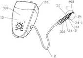
- Fig. 1is a schematic diagram of the three-dimensional structure of the visual scaler of the present invention.
- Fig. 1-1is an enlarged view of A in Fig. 1.
- Figure 1-2is a partial cross-sectional view of Figure 1.
- Figure 1-3is an enlarged view of B in Figure 1-2.
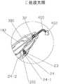
- FIG. 2is a schematic diagram of the three-dimensional structure of the visual scaler of the present invention including a three-dimensional camera system.
- Figure 2-1is an enlarged view of C in Figure 2.
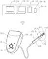
- Fig. 3is a schematic diagram of the three-dimensional structure of the visual scaler of the present invention with a foot switch.
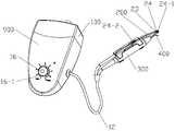
- Fig. 4is a three-dimensional structural diagram of the visual scaler of the present invention with a rotatable polishing head.
- Figure 4-1is an enlarged view of D in Figure 4.
- Fig. 4-2is a partial cross-sectional view of Fig. 4.
- Figure 4-3is an enlarged view of E in Figure 4-2.
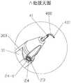
- FIG. 5is a schematic diagram of the three-dimensional structure when the lens of the visual scaler of the present invention with an adjustable serpentine tube lens angle is folded back.
- Fig. 5-1is a schematic diagram of the three-dimensional structure of the lens of Fig. 5 when placed on the upper part of the working part.
- Figure 5-2is an enlarged view of F in Figure 5-1.
- FIG. 6is a schematic diagram of the three-dimensional structure of the visual scaler of the present invention with the foldable connection structure when the lens is folded.
- Fig. 6-1is a schematic diagram of the three-dimensional structure of the lens of Fig. 6 when it is unfolded.
- Figure 6-2is an enlarged view of G in Figure 6-1.
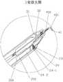
- FIG. 7is a schematic diagram of a three-dimensional structure of the visual scaler of the present invention with a retractable connecting mechanism when the lens is retracted.
- FIG. 7-1is a schematic diagram of the three-dimensional structure of the lens of FIG. 7 when it is extended.
- Fig. 7-2is an enlarged view of H in Fig. 7-1.
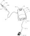
- Fig. 8is a three-dimensional schematic diagram of the visual scaler of the present invention when the detachable observation system is installed.
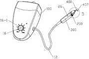
- Fig. 8-1is a schematic diagram of the state when the observation system of Fig. 8 is removed.
- 100is the host
- 200is the observation system
- 300is the handle
- 400is the working part
- 900is the visual scaler of the present invention.
- 11is a power supply system
- 12is a circuit system
- 13is a control system
- 14is a vibration generating system
- 15is a housing
- 16is a gear control system.
- 13-1is the power switch, 13-2 is the vibration drive switch, 13-21 is the foot switch; 16-1 is the gear knob.
- 141is the vibration generating system
- 142is the rotation generating system
- 23is a lighting system
- 24is a camera system
- 25is a connecting mechanism
- 26is a switch.
- 241is a stereo camera system
- 24-1is a camera
- 24-2is a data processing and output system
- 24-3is a display
- 25-1is a shaft.
- 24-31are smart phones
- 24-32are tablet computers
- 24-33are LCD monitors
- 24-34are computers.
- 31is the shell, and 32 is the motion transmission system.
- 401is a cleaning head
- 402is a polishing head
- Example 1The visual scaler of the present invention
- the visual scaler of the present inventionincludes a host 100, an observation system 200, a handle 300 and a working part 400.
- the host 100includes a power supply system 11, a circuit system 12, a control system 13, a motion generation system 14 and a housing 15.
- the control system 13is provided with a power switch 13-1 and a vibration drive switch 13-2.
- the power switch 13-1is provided on the housing 15, and the vibration-driven switch 13-2 is a foot switch 13-21, which is connected to the host 100 through an interface 15-1, refer to FIG. 3.
- the control system 13separates the power supply and working state control switches.
- the power supply and working state control switchescan also be combined into one switch, or other
- the form of vibration drive control on and off the applicantdoes not give specific examples here, but they do not deviate from the scope of protection of this application.
- the motion generating system 14is a vibration generating system 141 capable of generating vibration
- the vibration generating system 141can generate a vibration source
- the vibration sourcecan be transmitted to the working part 400 through the motion transmission system 32,
- the working part 400is driven to vibrate.
- the host 100is provided with a gear control system 16, and during clinical use, different vibration intensities can be selected according to different cleaning targets.
- the motion generating system 14may also be a rotation generating system 142 capable of generating rotation, such as generating mechanical rotation.
- the rotation generating system 142can generate mechanical rotation, and the motion transmission system 32 can drive the working part 400 to rotate.
- the vibration generating system 141is ultrasonic vibration generated by a piezoelectric transducer.
- the vibration generating system 141may also be an electromagnetic vibration device, such as an electromagnetic oscillator, or a magnetic suspension motor.
- electromagnetic vibration devicesuch as an electromagnetic oscillator, or a magnetic suspension motor.
- Those skilled in the artcan also design other various forms of vibration generating systems. The applicant does not give specific examples here, but they do not deviate from the protection scope of this application.
- the camera system 24includes a camera 24-1, a data processing and output system 24-2.
- the video data output by the data processing and output system 24-2 of the camera system 24can be displayed on the display 24-3 through a wired connection or a wireless connection, and the display 24-3 includes: Smartphone 24-31, or tablet computer 24-32, or LCD monitor 24-33, or computer 24-34.
- the camera system 24is disposed in the housing 31 of the handle 300.
- the camera system 24is installed in the housing 31, and the working part 400 can be easily replaced while ensuring observation.
- the waterproof treatmentcan be better performed.
- the surface of the lens 24-1will not be obscured by liquid.
- the wavelength of the light source of the illumination system 23can be changed.
- the illumination system 23can select light sources of different wavelengths according to different needs. If you need to observe dental plaque, you can choose a long-wave orange-red filter.
- the working part 400is a needle-shaped cleaning head 401.
- the cleaning head 401may also be a sharp cleaning tool of various shapes such as a shovel or a cone, which can quickly remove hard objects such as calculi on the tooth surface or between the teeth.
- the working part 400may also be a smooth grinding head 402. Referring to FIGS. 4 to 4-3, the grinding head 401 may be a round, arc-shaped, or flat-shaped grinding and polishing tool with a smooth surface. Able to polish and polish the surface of teeth.
- the working part 400can also be a root canal file, a periodontal probe and other oral treatment tools, which can be used in oral clinical treatment processes such as root canal treatment and periodontal treatment.
- a root canal filea periodontal probe and other oral treatment tools, which can be used in oral clinical treatment processes such as root canal treatment and periodontal treatment.
- the applicantdoes not give specific examples here, but they do not deviate from the scope of protection of this application.
- the working part 400is detachably installed on the motion transmission system 32.
- the working part 400is detachably installed at the distal end of the motion transmission system 32.
- the detachable installation methodcan facilitate the removal of the working part 400 from the handle 300 for replacement, storage and carrying.
- the working part 400is detachably mounted on the motion transmission system 32 through a threaded rotation connection.
- the working part 400can also be detachably mounted on the motion transmission system 32 through a concave-convex card fitting connection method or an interference fit connection method and other various methods. The applicant will not list them all here. , But does not depart from the scope of protection of this application.
- the working part 400is provided with a water outlet 41.
- the connecting end 42 of the working part 400is usually provided with a water outlet 41.
- the water outlet 41can be used to spray water to the working part for washing, and the polished calculus, dental plaque, dirt, etc. can be washed away from the tooth surface in time, making the tooth polishing process more comfortable and convenient.
- the working part 400When in use, install the working part 400 at the far end of the motion transmission system 32, connect the power supply system 11 of the host 100, turn on the power switch 13-1, and then turn on the switch 26 of the observation system 200 , The camera system 24 works. At this time, the doctor steps on the foot switches 13-21, the vibration generating system 141 generates a vibration source, and the vibration source is transmitted to the working part 400 via the motion transmission system 32, and the working part 400 generates vibration. Depending on the cleaning target, adjust the gear knob 16-1 of the gear control system 16 to a suitable gear, and the doctor can look at the display 24-3 and use the visual scaler of the present invention to perform treatment on the teeth and oral cavity. Clean, very safe and convenient for clinical use. When the observation system 200 adopts a lens module with an automatic zoom function, the field of view can be enlarged or reduced as required, which can further improve the accuracy and clarity of observation.
- the camera system 24includes one camera 24-1.
- the camera system 24may be a stereo camera system 241.
- the stereo camera system 241includes at least two cameras 24-1.
- the stereo camera system 241can form a 3D image in clinical use, and can better observe the spatial position of the working part 400 during the cleaning process, and the clinical use is safer.
- the visual scaler of this embodimentis designed with an observation system 200 close to the working part 400, the doctor can observe the oral cleaning and treatment process in real time through the display 24-3, and the doctor does not need to observe the viewing angle during the treatment process. Adjusting the body posture makes the clinical treatment process safer and the doctors more relaxed and comfortable.
- Embodiment 2The visual scaler of the present invention with adjustable lens
- the difference between this embodiment and Embodiment 1is that in this embodiment, the lens 24-1 of the camera system 24 extends from the housing 31 through the connection mechanism 25, and is adjusted The shape and position of the connecting mechanism 25 can adjust the position and angle of the lens 24-1.
- the connecting structure 25can be designed as a deformable serpentine tube structure.
- the observation angle of the camera 24-1can be adjusted by adjusting the serpentine tube.
- the connecting structure 25can be folded or unfolded outside the handle 300.
- the connecting mechanism 25can be folded or unfolded around the rotating shaft 25-1, and the real-time folding or unfolding of the connecting mechanism 25 can drive the lens 24-1 to move outside the handle 300.
- the connecting mechanism 25is folded, and the lens 24-1 is recycled to facilitate the installation and replacement of the working part 400; when the working part 400 is installed, the The connecting mechanism 25 is unfolded, and the lens 24-1 is located above the working part 400, so that the working process of the working part 400 can be conveniently observed.
- the connecting mechanism 25can also adjust the working position of the lens 24-1 by driving the lens 24-1 to move back and forth along the handle 300.
- the connecting mechanism 25is a chute mechanism.
- the connecting mechanism 25may also be a hinge mechanism or a gear mechanism or other motion mechanisms. Those skilled in the art can also design other motion mechanisms as needed, without departing from the scope of protection of this application.
- the connecting mechanism 25drives the lens 24-1 to slide backward without blocking the installation and replacement of the working part 400.
- the The connecting mechanism 25drives the lens 24-1 to slide toward the working part 400, and the lens 24-1 can observe the working process of the working part 400.
- the surface of the camera 24-1 of the camera system 24adopts a waterproof design.
- the surface of the camera 24-1can be treated with an anti-fog coating. After the anti-fog coating is processed, even if a small amount of water vapor is formed on the front end of the camera 24-1 to condense on the surface of the camera 24-1, It does not exist in the form of water drops, but transforms into a transparent water film, and does not form a foggy phenomenon in front of the camera 24-1, and the observation effect in clinical use is clearer and stable.
- the surface of the camera 24-1can also be treated with a hydrophobic coating. After being treated with the hydrophobic coating, water droplets will quickly condense and slide off on the surface of the lens 24-1, so as to maintain a clear vision.
- the camera 24-1 of the camera system 24can use the vibration generated by the vibration generating system 141 to remove water droplets attached to the surface of the camera 24-1 to maintain a clear view.
- the vibration generated by the vibration generating system 141can cause the water droplets that may be attached to the surface of the lens 24-1 to fall off the surface of the lens 24-1 along with the vibration, thereby maintaining a clear view.
- the position and angle of the camera 24-1can be adjusted as required, so that the use process is safer and more convenient.
- Embodiment 3The visual scaler of the present invention with detachable lens
- the difference between this embodiment and Embodiment 2is that in this embodiment, the observation system 200 is detachably mounted on the handle 300.
- the observation system 200is connected to the handle 300 by a concave-convex card fit.
- the observation system 200may also be connected to the handle 300 by means of rotation connection or interference fit. The applicant will not list them one by one here, but they do not deviate from the protection scope of this application.
- the observation system 200When working, the observation system 200 is installed on the handle 300, and after use, the observation system 200 is removed, which is more convenient for storage and carrying.
Landscapes
- Health & Medical Sciences (AREA)
- Life Sciences & Earth Sciences (AREA)
- Surgery (AREA)
- Veterinary Medicine (AREA)
- Public Health (AREA)
- General Health & Medical Sciences (AREA)
- Animal Behavior & Ethology (AREA)
- Dentistry (AREA)
- Optics & Photonics (AREA)
- Pathology (AREA)
- Biomedical Technology (AREA)
- Heart & Thoracic Surgery (AREA)
- Medical Informatics (AREA)
- Molecular Biology (AREA)
- Radiology & Medical Imaging (AREA)
- Engineering & Computer Science (AREA)
- Physics & Mathematics (AREA)
- Nuclear Medicine, Radiotherapy & Molecular Imaging (AREA)
- Biophysics (AREA)
- Oral & Maxillofacial Surgery (AREA)
- Epidemiology (AREA)
- Dental Tools And Instruments Or Auxiliary Dental Instruments (AREA)
- Endoscopes (AREA)
Abstract
Description
Translated fromChinese本发明涉及一种口腔清洁用具,特别是用于清洁牙齿、齿间的可视洁牙机。The invention relates to an oral cleaning appliance, in particular to a visual scaler used for cleaning teeth and between teeth.
当长时间牙齿清洁不干净,或者长期吸烟、喝茶、饮酒时,就非常容易在牙齿表面产生结石、牙菌斑、色素沉积等牙齿问题。目前清除牙结石、牙菌斑、色素沉积等牙齿问题的常规途径是到专业的口腔医院进行洗牙。When the teeth are not clean for a long time, or when smoking, drinking tea, or drinking for a long time, it is very easy to produce dental problems such as stones, plaque, and pigmentation on the surface of the teeth. At present, the conventional way to remove dental calculus, dental plaque, pigmentation and other dental problems is to go to a professional dental hospital for dental cleaning.
目前洗牙过程中常用的清除牙结石、牙菌斑、色素沉积的方式是通过高速旋转或振动的洁牙器工作头,如超声洁牙机等,伸入口腔,在工作头的摩擦或振动作用下,松动菌斑,打碎牙齿表面的污物,从而达到清洁牙结石、牙菌斑、色素沉积的的目的。At present, the common way to remove calculus, plaque, and pigmentation in the process of cleaning teeth is through the high-speed rotating or vibrating dental scaler working head, such as ultrasonic scaler, etc., which is inserted into the oral cavity and rubs or vibrates on the working head. Under the action, the plaque is loosened and the dirt on the surface of the tooth is broken, so as to achieve the purpose of cleaning calculus, dental plaque and pigment deposition.
由于工作头需要伸入口腔内部,而口腔内部的光线很暗,因此非常难看清口腔内的情况,所以现有技术通常要牙医在牙科诊所内进行,依靠专业器械,借助牙科治疗工作台或牙科治疗椅,对患者口腔内的牙结石、牙菌斑、色素沉积、舌苔等进行清洁。Since the working head needs to be inserted into the oral cavity, and the light inside the oral cavity is very dark, it is very difficult to see the situation in the oral cavity. Therefore, the prior art usually requires a dentist to perform it in a dental office, relying on professional equipment and using dental treatment benches or dental The treatment chair cleans the dental calculus, dental plaque, pigmentation, and tongue coating in the patient's mouth.
清洁过程中,医生通常依靠外部光源对口腔进行照明,但在操作过程中,由于医生需要低头对口腔内部进行观察,非常容易挡住光源照明。尤其是,当对口腔深部的磨牙外侧进行清洁时,加之工作部位处于口腔深处和脸颊肌肉的遮挡,操作过程中医生观察非常困难,经常需要调整头部姿态或弯曲腰部来适应洁牙时的视野观察,而且医生这种长期低头工作的状态非常容易带来颈椎病、腰椎等疾病。During the cleaning process, the doctor usually relies on an external light source to illuminate the oral cavity. However, during the operation, since the doctor needs to lower his head to observe the inside of the oral cavity, it is very easy to block the light source from illuminating. Especially, when cleaning the outer side of the molars in the deep part of the mouth, and the working part is in the deep part of the mouth and the cheek muscles, it is very difficult for the doctor to observe during the operation. It is often necessary to adjust the head posture or bend the waist to adapt to the cleaning. Observation of the field of vision, and the doctor's long-term low-head work state is very easy to cause cervical spondylosis, lumbar spine and other diseases.
为了克服现有技术的这些缺点,需要开发一种能将口腔内部状态直接显示在显示器上,能在可视状态下对牙齿部位有的放矢地进行定点清洁、打磨、抛光的可视洁牙机,牙医可以保持相对舒适的姿态,进行洁牙等医疗工作,减轻疲劳,预防颈椎病、腰椎等疾病。In order to overcome these shortcomings of the prior art, it is necessary to develop a visual dental scaler that can directly display the internal state of the oral cavity on the display, and can perform targeted cleaning, polishing, and polishing of the teeth in a visual state. It can maintain a relatively comfortable posture, perform medical work such as cleaning teeth, reduce fatigue, and prevent cervical spondylosis, lumbar spine and other diseases.
发明内容Summary of the invention
本发明之可视洁牙机能在观察系统的作用下,在可视状态下,利用专门的工作部对牙 齿进行清洁、打磨、抛光,有效解决牙结石、牙菌斑、色素沉积等口腔问题。The visual scaler of the present invention can clean, polish and polish the teeth under the action of the observation system and in the visual state, so as to effectively solve oral problems such as dental calculus, dental plaque, and pigment deposition.
本发明之可视洁牙机,其特征在于:所述可视洁牙机900含主机100、观察系统200、手柄300及工作部400;The visual scaler of the present invention is characterized in that: the
A、所述主机100含电源系统11、电路系统12、控制系统13、运动发生系统14、壳体15;所述电源系统11、所述控制系统13、所述运动发生系统14通过所述电路系统12连接在一起;所述主机100通过所述电路系统12和所述手柄300连接在一起;A. The
B、所述观察系统200含照明系统23、摄像系统24和开关26;通过所述电路系统12及所述控制系统13将所述照明系统23、所述摄像系统24、所述电源系统11及所述开关26连接在一起;B. The
C、所述手柄300含外壳31、运动传递系统32;所述运动传递系统32的近端与所述运动发生系统14的远端相连接,所述运动传递系统32的远端和所述工作部400的近端相连接;C. The
D、所述工作部400的工作部分在所述观察系统200的所述摄像系统24的视野内。D. The working part of the working
本发明之可视洁牙机,将观察系统和工作部有效的整合在一起,所述电路系统12和所述控制系统13既能将所述电源系统11接通所述运动发生系统14,使所述运动发生系统14产生的运动经所述运动传递系统32传导至所述工作部,带动所述工作部400进行工作;又能接通所述观察系统200的照明系统23、摄像头系统24和开关26,向所述观察系统200提供工作所需的电力,并控制所述观察系统200进行工作。因此,本申请中,所述主机100既能够驱动所述工作部400,又能给所述观察系统200的照明系统23、摄像头系统24等提供电源和控制系统。所述观察系统200能通过所述摄像系统24对清洁过程进行实时观察,实现一边清洁,一边在显示器上即时观察用工作部400对牙齿表面的牙结石、牙菌斑和色素沉积进行清洁的过程和清洁效果,达到对牙齿进行有效清洁和打磨抛光的目的。这种所述观察系统200抵近工作部400进行实时视频观察的机构设计,提高了观察的准确性和清晰度,同时还提高了牙医的工作时的舒适性。The visual scaler of the present invention effectively integrates the observation system and the working part. The
所述运动发生系统14是能产生振动的振动发生系统141,或是能产生转动的转动发生系统142。所述振动发生系统141能产生振动源,振动源能经所述运动传递系统32传导至所述工作部400,带动所述工作部400发生振动。所述转动发生系统142能产生转动源,经所述运动传递系统32能带动所述工作部400发生转动。The
所述振动发生系统141是电磁振动装置,含电磁振荡器,或磁悬马达。The vibration generating
所述振动发生系统141是压电换能器产生的超声波振动。The vibration generating
所述振动发生系统141是电机驱动的偏心轮振动机构。这种电机驱动的偏心轮振动机构,振动频率及振幅调整方便,成本低。The vibration generating
申请人在此只列举了上述几种具体的振动发生方式,本领域的技术人员可以根据需要设计出不同的振动发生系统,都并不脱离本申请的请求保护范围。The applicant only lists the above-mentioned specific vibration generation methods. Those skilled in the art can design different vibration generation systems according to their needs, and they do not deviate from the scope of protection claimed in this application.
所述摄像系统24含摄像头24-1、数据处理及输出系统24-2。The
进一步,所述摄像系统24是立体摄像系统241,所述立体摄像系统241至少含2个摄像头24-1。多个摄像头的设计,可以形成3D图像,在清洁过程中可以更好地观察所述工作部400的空间位置。Further, the
所述摄像系统24的数据处理及输出系统24-2输出的视频数据能通过有线连接或无线连接的方式在显示器24-3上显示,所述显示器24-3包括:智能手机24-31、或平板电脑24-32、或液晶显示器24-33、或电脑24-34。The video data output by the data processing and output system 24-2 of the
所述摄像系统24设置在所述手柄300的外壳31内。所述摄像系统24安装在所述外壳31内,在保证观察的同时,可以方便地进行所述工作部400的更换。同时由于密封在所述外壳31内,可以更好地进行防水处理,清洁过程中,所述镜头24-1表面不会由于液体的遮挡造成观察不清。The
所述摄像系统24的摄像头24-1通过连接结构25从所述外壳31内伸出。所述摄像头24-1可以从所述外壳31内伸出,清洁过程中,可以根据需要调整所述镜头24-1的位置和角度,使用过程更加方便。The camera 24-1 of the
所述连接结构25可以调整所述摄像头24-1的观察角度。所述连接结构25可以设计成可变形的蛇形管结构,临床使用中,通过调整蛇形管就可以调整所述摄像头24-1的观察角度。The connecting
所述连接结构25可以在所述手柄300外部折叠或者展开。所述连接机构25的折叠或者展开可以带动所述镜头24-1在所述手柄300外部运动。当需要安装或拆卸所述工作部400时,将所述连接机构25折叠,所述镜头24-1回收,便于所述工作部400的安装和更换;当所述工作部400安装好后,将所述连接机构25展开,所述镜头24-1位于所述工作部400的上方,可以方便地观察所述工作部400的工作过程。The connecting
所述连接机构25可以带动所述镜头24-1沿所述手柄300来回运动。所述连接机构25可以是滑槽机构、或者铰链机构、或者齿轮机构。本领域的技术人员也可以根据需要设计出其它的运动机构,都不脱离本申请的保护范围。需要安装或更换所述工作部400时,所述连接机构25带动所述镜头24-1向后滑动,不遮挡所述工作部400的安装和更换,所述工作部400安装好后,所述连接机构25带动所述镜头24-1向所述工作部400滑动,所述镜头24-1可以观察所述工作部400的工作过程。The
所述摄像系统24的摄像头24-1能借助所述振动发生系统141产生的振动来去除附着在摄像头24-1的表面上的水珠而保持视野清晰。所述振动发生系统141产生的振动可以使得所述镜头24-1表面可能附着的水珠随着振动而从所述镜头24-1的表面脱落,从而保持视野清晰。The camera 24-1 of the
所述观察系统200可拆卸地安装在所述手柄300上。所述观察系统200还可以可拆卸地安装在所述手柄300上,工作时,将所述观察系统200安装在所述手柄300上,使用完毕,将所述观察系统200拆下,收纳和携带更加方便。所述观察系统200可以通过凹凸卡配合方式、或旋转连接方式、或过盈配合方式等连接在所述手柄300上。The
所述照明系统23的光源的波长可以变化。所述照明系统23,可以根据不同的需要选择不同波长的光源。如需要观察牙菌斑时,可以选用长波橙红滤光器。The wavelength of the light source of the
所述摄像系统24的摄像头24-1的表面采用防水设计。所述摄像头24-1表面可以进行防雾涂层处理,通过防雾涂层处理后,即使在所述摄像头24-1的前端形成少量的水蒸气在所述摄像头24-1表面结露,也不会以水滴状存在,而是转变成透明的水膜,不会在所述摄像头24-1前形成雾状现象,临床使用中观察效果更清晰、稳定。The surface of the camera 24-1 of the
进一步,所述摄像系统24的摄像头24-1的表面设有疏水涂层。疏水涂层的处理可以使得水珠在所述镜头24-1表面快速凝结后滑落,无法停留在所述镜头24-1的表面,从而保持了所述镜头24-1表面的清晰。Further, the surface of the camera 24-1 of the
所述工作部400是清洁头401、或打磨头402。所述工作部可以是清洁头401,也可以是打磨头402。所述清洁头401可以是针状的、铲状的或锥状的等各种形状的锋利的清洁工具。所述清洁头401可以将牙齿表面或牙缝处的牙结石等坚硬的物体快速地清除。所述打磨头401可以是圆形的、圆弧形的、或平面状的表面光滑的打磨抛光工具,能够对牙齿表面进行打磨、抛光。The working
所述工作部400还能是根管锉、牙周探针等其它口腔治疗工具,可以用于根管治疗、牙周治疗等口腔临床治疗过程。申请人在此不具体举例说明,但都不脱离本申请的保护范围。The working
所述工作部400是可拆卸地安装在所述运动传递系统32上。通常,所述工作部400可拆卸地安装在所述运动传递系统32的远端。可拆卸的安装方式,可以方便将所述工作部400从所述手柄300上拆下进行更换、收纳和携带。The working
所述工作部400通过凹凸卡配合连接方式,或过盈配合连接方式,或旋转连接方式可拆卸地安装在所述运动传递系统32上。申请人在此只列举了上述几种连接方式,本领域的技术人员可以根据需要设计出各种不同的连接方式,都不脱离本申请的保护范围。The working
所述可视洁牙机900的工作部400上设有出水口41。上述工作部400的连接端42通常设有出水口41。临床使用时,利用所述出水口41可以向工作部位喷水冲洗,及时将打磨下来的牙结石、牙菌斑、污物等从牙齿表面冲离,使得牙齿打磨过程更加舒适、便捷。The working
临床使用中,将所述工作部400安装在所述运动传递系统32的远端,接通所述主机100的电源系统11,打开所述观察系统200的开关26,所述摄像系统24进行工作,医生即可看着所述显示器24-3,用本发明之可视洁牙机对牙齿和口腔进行清洁,临床使用非常安全、方便。当所述观察系统200采用具有自动变焦功能的镜头模组时,能根据需要放大或缩小视野,可以进一步提高观察的准确性和清晰度。In clinical use, the working
本发明之可视洁牙机含主机100、观察系统200、手柄300和工作部400。所述观察系统200含照明系统23和摄像系统24,所述摄像系统24的摄像头24-1拍摄到的图像能及时传输到所述显示器24-3上,从而实现一边清洁,一边即时观察用工作部400对牙齿表面的牙结石、牙菌斑和色素沉积进行清洁的过程和清洁效果,达到对牙齿进行有效清洁和打磨抛光的目的。所述观察系统200的设计,既保证了清洁过程中能实时观察,临床操作更加安全,同时医生可以看着所述显示器24-3进行清洁,工作过程更加轻松。这种所述观察系统200抵近工作部400进行实时视频观察的机构设计,尤其是采用能具有自动变焦功能的镜头模组时,能放大或缩小视野,提高了观察的准确性和清晰度,同时还提高了牙医的工作时的舒适性。The visual scaler of the present invention includes a
图1是本发明之可视洁牙机的立体结构示意图。Fig. 1 is a schematic diagram of the three-dimensional structure of the visual scaler of the present invention.
图1-1是图1的A处放大图。Fig. 1-1 is an enlarged view of A in Fig. 1.
图1-2是图1的局部剖视图。Figure 1-2 is a partial cross-sectional view of Figure 1.
图1-3是图1-2的B处放大图。Figure 1-3 is an enlarged view of B in Figure 1-2.
图2是含立体摄像系统的本发明之可视洁牙机的立体结构示意图。2 is a schematic diagram of the three-dimensional structure of the visual scaler of the present invention including a three-dimensional camera system.
图2-1是图2的C处放大图。Figure 2-1 is an enlarged view of C in Figure 2.
图3是带脚踏开关的本发明之可视洁牙机的立体结构示意图。Fig. 3 is a schematic diagram of the three-dimensional structure of the visual scaler of the present invention with a foot switch.
图4是带可转动的打磨头的本发明之可视洁牙机的立体结构示意图。Fig. 4 is a three-dimensional structural diagram of the visual scaler of the present invention with a rotatable polishing head.
图4-1是图4的D处放大图。Figure 4-1 is an enlarged view of D in Figure 4.
图4-2是图4的局部剖视图。Fig. 4-2 is a partial cross-sectional view of Fig. 4.
图4-3是图4-2的E处放大图。Figure 4-3 is an enlarged view of E in Figure 4-2.
图5是蛇形管镜头角度可调的本发明之可视洁牙机的镜头折回时的立体结构示意图。FIG. 5 is a schematic diagram of the three-dimensional structure when the lens of the visual scaler of the present invention with an adjustable serpentine tube lens angle is folded back.
图5-1是图5的镜头置于工作部上部时的立体结构示意图。Fig. 5-1 is a schematic diagram of the three-dimensional structure of the lens of Fig. 5 when placed on the upper part of the working part.
图5-2是图5-1的F处放大图。Figure 5-2 is an enlarged view of F in Figure 5-1.
图6是连接结构可折叠的本发明之可视洁牙机的镜头折叠时的立体结构示意图。6 is a schematic diagram of the three-dimensional structure of the visual scaler of the present invention with the foldable connection structure when the lens is folded.
图6-1是图6镜头展开时的立体结构示意图。Fig. 6-1 is a schematic diagram of the three-dimensional structure of the lens of Fig. 6 when it is unfolded.
图6-2是图6-1的G处放大图。Figure 6-2 is an enlarged view of G in Figure 6-1.
图7是连接机构可伸缩的本发明之可视洁牙机的镜头收回时的立体结构示意图。FIG. 7 is a schematic diagram of a three-dimensional structure of the visual scaler of the present invention with a retractable connecting mechanism when the lens is retracted.
图7-1是图7的镜头伸出时的立体结构示意图。FIG. 7-1 is a schematic diagram of the three-dimensional structure of the lens of FIG. 7 when it is extended.
图7-2是图7-1的H处放大图。Fig. 7-2 is an enlarged view of H in Fig. 7-1.
图8是可拆卸的观察系统安装时的本发明之可视洁牙机的立体结构示意图。Fig. 8 is a three-dimensional schematic diagram of the visual scaler of the present invention when the detachable observation system is installed.
图8-1是图8的观察系统拆下时的状态示意图。Fig. 8-1 is a schematic diagram of the state when the observation system of Fig. 8 is removed.
上述图中:In the above figure:
100为主机,200为观察系统,300为手柄,400为工作部,900为本发明之可视洁牙机。100 is the host, 200 is the observation system, 300 is the handle, 400 is the working part, and 900 is the visual scaler of the present invention.
主机上:On the host:
11为电源系统,12为电路系统,13为控制系统,14为振动发生系统,15为壳体, 16为档位控制系统。11 is a power supply system, 12 is a circuit system, 13 is a control system, 14 is a vibration generating system, 15 is a housing, and 16 is a gear control system.
13-1为电源开关,13-2为振动驱动开关,13-21为脚踏开关;16-1为档位旋钮。13-1 is the power switch, 13-2 is the vibration drive switch, 13-21 is the foot switch; 16-1 is the gear knob.
141为振动发生系统,142为转动发生系统141 is the vibration generating system, and 142 is the rotation generating system
观察系统上:Observe the system:
23为照明系统,24为摄像系统,25为连接机构,26为开关。23 is a lighting system, 24 is a camera system, 25 is a connecting mechanism, and 26 is a switch.
241为立体摄像系统;24-1为摄像头,24-2为数据处理及输出系统,24-3为显示器;25-1为转轴。241 is a stereo camera system; 24-1 is a camera, 24-2 is a data processing and output system, 24-3 is a display; 25-1 is a shaft.
24-31为智能手机,24-32为平板电脑,24-33为液晶显示器,24-34为电脑。24-31 are smart phones, 24-32 are tablet computers, 24-33 are LCD monitors, and 24-34 are computers.
手柄上:On the handle:
31为外壳,32为运动传递系统。31 is the shell, and 32 is the motion transmission system.
工作部上:On the work department:
401为清洁头,402为打磨头。401 is a cleaning head, and 402 is a polishing head.
41为出水口。41 is the water outlet.
实施例1:本发明之可视洁牙机Example 1: The visual scaler of the present invention
参考图1至图1-3,本发明之可视洁牙机含主机100、观察系统200、手柄300及工作部400。Referring to FIGS. 1 to 1-3, the visual scaler of the present invention includes a
所述主机100含电源系统11、电路系统12、控制系统13、运动发生系统14及壳体15。所述控制系统13上设有电源开关13-1和振动驱动开关13-2。所述电源开关13-1设在所述壳体15上,所述振动驱动开关13-2是脚踏开关13-21,通过接口15-1连接在所述主机100上,参考图3。The
本实施例中,为保证工作过程的安全,所述控制系统13上将电源和工作状态的控制开关分开设立,实际应用中,电源和工作状态的控制开关也可以合并成一个开关,或者采用其它形式的振动驱动控制开,关申请人在此不具体举例说明,但都不脱离本申请的保护范围。In this embodiment, in order to ensure the safety of the work process, the
本实施例中,所述运动发生系统14是能产生振动的振动发生系统141,所述振动发生系统141能产生振动源,振动源能经所述运动传递系统32传导至所述工作部400,带动 所述工作部400发生振动。所述主机100上设有档位控制系统16,临床使用时,可以根据不同的清洁目标,选取不同的振动强度。In this embodiment, the
参考图4-2和图4-3,所述运动发生系统14也可以是能产生转动的转动发生系统142,如产生机械旋转转动。所述转动发生系统142能产生机械旋转转动,经所述运动传递系统32能带动所述工作部400发生转动。Referring to FIGS. 4-2 and 4-3, the
本实施例中,所述振动发生系统141是压电换能器产生的超声波振动。所述振动发生系统141也可以是电磁振动装置,如电磁振荡器,或磁悬马达。本领域的技术人员还可以设计出其它各种形式的振动发生系统,申请人在此不具体举例说明,但都并不脱离本申请的保护范围。In this embodiment, the
所述摄像系统24含摄像头24-1、数据处理及输出系统24-2。The
参考图6和图7,所述摄像系统24的数据处理及输出系统24-2输出的视频数据能通过有线连接或无线连接的方式在显示器24-3上显示,所述显示器24-3包括:智能手机24-31、或平板电脑24-32、或液晶显示器24-33、或电脑24-34。6 and 7, the video data output by the data processing and output system 24-2 of the
参考图1至图1-3,本实施例中,所述摄像系统24设置在所述手柄300的外壳31内。所述摄像系统24安装在所述外壳31内,在保证观察的同时,可以方便地进行所述工作部400的更换。同时由于密封在所述外壳31内,可以更好地进行防水处理,清洁过程中,所述镜头24-1表面不会由于液体的遮挡造成观察不清。Referring to FIGS. 1 to 1-3, in this embodiment, the
所述照明系统23的光源的波长可以变化。所述照明系统23,可以根据不同的需要选择不同波长的光源。如需要观察牙菌斑时,可以选用长波橙红滤光器。The wavelength of the light source of the
参考图1,本实施例中,所述工作部400是针状的清洁头401。所述清洁头401还可以是铲状的或锥状的等各种形状的锋利的清洁工具,可以将牙齿表面或牙缝处的牙结石等坚硬的物体快速地清除。所述工作部400也可以是光滑的打磨头402,参考图4至图4-3,所述打磨头401可以是圆形的、圆弧形的、或平面状的表面光滑的打磨抛光工具,能够对牙齿表面进行打磨、抛光。1, in this embodiment, the working
所述工作部400还能是根管锉、牙周探针等其它口腔治疗工具,可以用于根管治疗、牙周治疗等口腔临床治疗过程。申请人在此不具体举例说明,但都不脱离本申请的保护范围。The working
申请人在此只列举了上述几种结构的工作部,实际应用中,本领域的技术人员还可以 根据需要设计处不同的清洁工具安装在所述运动传递系统32上,对牙齿和口腔进行清洁,申请人在此不一一列举,但都不脱离本申请的保护范围。The applicant only lists the working parts with the above-mentioned structures. In practical applications, those skilled in the art can also design different cleaning tools to be installed on the
本实施例中,所述工作部400是可拆卸地安装在所述运动传递系统32上。通常,所述工作部400可拆卸地安装在所述运动传递系统32的远端。可拆卸的安装方式,可以方便将所述工作部400从所述手柄300上拆下进行更换、收纳和携带。In this embodiment, the working
参考图1-2和图1-3,本实施例中,所述工作部400通过螺纹旋转连接的方式可拆卸地安装在所述运动传递系统32上。实际应用中,所述工作部400还可以通过凹凸卡配合连接方式,或过盈配合连接方式等其它各种方式可拆卸地安装在所述运动传递系统32上,申请人在此不一一列举,但都不脱离本申请的保护范围。Referring to FIGS. 1-2 and FIGS. 1-3, in this embodiment, the working
参考图1-3,本实施例中,所述工作部400上设有出水口41。上述工作部400的连接端42通常设有出水口41。临床使用时,利用所述出水口41可以向工作部位喷水冲洗,及时将打磨下来的牙结石、牙菌斑、污物等从牙齿表面冲离,使得牙齿打磨过程更加舒适、便捷。Referring to FIGS. 1-3, in this embodiment, the working
使用时,将所述工作部400安装在所述运动传递系统32的远端,连接所述主机100的电源系统11,打开所述电源开关13-1,然后开启所述观察系统200的开关26,所述摄像系统24进行工作。此时,医生踩下脚踏开关13-21,所述振动发生系统141产生振动源,振动源经所述运动传递系统32传递给所述工作部400,所述工作部400产生振动,医生根据清洁目标的不同,调整档位控制系统16的档位旋钮16-1至合适的档位,医生即可看着所述显示器24-3,用本发明之可视洁牙机对牙齿和口腔进行清洁,临床使用非常安全、方便。当所述观察系统200采用具有自动变焦功能的镜头模组时,能根据需要放大或缩小视野,可以进一步提高观察的准确性和清晰度。When in use, install the working
本实施例中,所述摄像系统24含1个摄像头24-1,实际应用中,所述摄像系统24可以是立体摄像系统241,所述立体摄像系统241至少含2个摄像头24-1,参考图2和图2-1。所述立体摄像系统241在临床使用中可以形成3D图像,在清洁过程中可以更好地观察所述工作部400的空间位置,临床使用更加安全。In this embodiment, the
本实施例之可视洁牙机由于设计有靠近所述工作部400的观察系统200,医生可以通过所述显示器24-3对口腔清洁及治疗过程实时观察,医生治疗过程中无需再为了观察视角而调整身体姿势,临床治疗过程更加安全,医生也更加轻松、舒适。Since the visual scaler of this embodiment is designed with an
实施例2:镜头可调整的本发明之可视洁牙机Embodiment 2: The visual scaler of the present invention with adjustable lens
参考图5至图7-2,本实施例与实施例1的区别在于,本实施例中,所述摄像系统24的镜头24-1通过连接机构25从所述外壳31中伸出,通过调整所述连接机构25的形状和位置,可以调整所述镜头24-1的位置和角度。Referring to FIGS. 5 to 7-2, the difference between this embodiment and Embodiment 1 is that in this embodiment, the lens 24-1 of the
参考图5至图5-2,所述连接结构25可以设计成可变形的蛇形管结构,临床使用中,通过调整蛇形管就可以调整所述摄像头24-1的观察角度。Referring to FIGS. 5 to 5-2, the connecting
参考图6至图6-2,所述连接结构25可以在所述手柄300外部折叠或者展开。所述连接机构25绕转轴25-1可以折叠或展开,实时连接机构25的折叠或者展开可以带动所述镜头24-1在所述手柄300外部运动。当需要安装或拆卸所述工作部400时,将所述连接机构25折叠,所述镜头24-1回收,便于所述工作部400的安装和更换;当所述工作部400安装好后,将所述连接机构25展开,所述镜头24-1位于所述工作部400的上方,可以方便地观察所述工作部400的工作过程。6 to 6-2, the connecting
参考图7至图7-2,所述连接机构25还可以通过带动所述镜头24-1沿所述手柄300来回运动来调整所述镜头24-1的工作位置。本实施例中,所述连接机构25是滑槽机构。所述连接机构25也可以是或者铰链机构、或者齿轮机构等其它运动机构。本领域的技术人员也可以根据需要设计出其它的运动机构,都不脱离本申请的保护范围。需要安装或更换所述工作部400时,所述连接机构25带动所述镜头24-1向后滑动,不遮挡所述工作部400的安装和更换,所述工作部400安装好后,所述连接机构25带动所述镜头24-1向所述工作部400滑动,所述镜头24-1可以观察所述工作部400的工作过程。Referring to FIGS. 7 to 7-2, the connecting
由于所述镜头24-1通过所述连接机构25从所述外壳31中伸出,为保证使用过程观察效果的清晰和稳定,所述摄像系统24的摄像头24-1的表面采用防水设计。所述摄像头24-1表面可以进行防雾涂层处理,通过防雾涂层处理后,即使在所述摄像头24-1的前端形成少量的水蒸气在所述摄像头24-1表面结露,也不会以水滴状存在,而是转变成透明的水膜,不会在所述摄像头24-1前形成雾状现象,临床使用中观察效果更清晰、稳定。Since the lens 24-1 extends from the
所述摄像头24-1表面还可以进行疏水涂层处理。经疏水涂层处理后,水珠在所述镜头24-1的表面会快速凝结并滑落,从而保持视野的清晰。The surface of the camera 24-1 can also be treated with a hydrophobic coating. After being treated with the hydrophobic coating, water droplets will quickly condense and slide off on the surface of the lens 24-1, so as to maintain a clear vision.
所述摄像系统24的摄像头24-1能借助所述振动发生系统141产生的振动来去除附着在摄像头24-1的表面上的水珠而保持视野清晰。所述振动发生系统141产生的振动可以 使得所述镜头24-1表面可能附着的水珠随着振动而从所述镜头24-1的表面脱落,从而保持视野清晰。The camera 24-1 of the
本实施例章,临床使用时,可以根据需要,调整所述摄像头24-1的位置和角度,使用过程更加安全、方便。In this embodiment chapter, during clinical use, the position and angle of the camera 24-1 can be adjusted as required, so that the use process is safer and more convenient.
实施例3:镜头可拆卸的本发明之可视洁牙机Embodiment 3: The visual scaler of the present invention with detachable lens
参考图8和图8-1,本实施例与实施例2的区别在于,本实施例中,所述观察系统200可拆卸地安装在所述手柄300上。Referring to FIGS. 8 and 8-1, the difference between this embodiment and Embodiment 2 is that in this embodiment, the
本实施例中,所述观察系统200通过凹凸卡配合方式连接在所述手柄300上。实际应用中,所述观察系统200还可以通过旋转连接方式、或过盈配合方式等其它连接在所述手柄300上,申请人在此不一一列举,但都不脱离本申请的保护范围。In this embodiment, the
工作时,将所述观察系统200安装在所述手柄300上,使用完毕,将所述观察系统200拆下,收纳和携带更加方便。When working, the
应该注意,本文中公开和说明的结构可以用其它效果相同的结构代替,同时本发明所介绍的实施例并非实现本发明的唯一结构。虽然本发明的优先实施例已在本文中予以介绍和说明,但本领域内的技术人员都清楚知道这些实施例不过是举例说明而己,本领域内的技术人员可以做出无数的变化、改进和代替,而不会脱离本发明,因此,应按照本发明所附的权利要求书的精神和范围来的界定本发明的保护范围。It should be noted that the structures disclosed and described herein can be replaced by other structures with the same effect, and the embodiments described in the present invention are not the only structure for realizing the present invention. Although the preferred embodiments of the present invention have been introduced and illustrated in this article, those skilled in the art know that these embodiments are only examples, and those skilled in the art can make numerous changes and improvements. And instead of without departing from the present invention, therefore, the protection scope of the present invention should be defined in accordance with the spirit and scope of the appended claims of the present invention.
Claims (22)
Translated fromChineseApplications Claiming Priority (2)
| Application Number | Priority Date | Filing Date | Title |
|---|---|---|---|
| CN201910493255.9ACN112043443A (en) | 2019-06-07 | 2019-06-07 | Visual scaler |
| CN201910493255.9 | 2019-06-07 |
Publications (1)
| Publication Number | Publication Date |
|---|---|
| WO2020244386A1true WO2020244386A1 (en) | 2020-12-10 |
Family
ID=73609573
Family Applications (1)
| Application Number | Title | Priority Date | Filing Date |
|---|---|---|---|
| PCT/CN2020/091303CeasedWO2020244386A1 (en) | 2019-06-07 | 2020-05-20 | Visual ultrasonic scaler |
Country Status (2)
| Country | Link |
|---|---|
| CN (1) | CN112043443A (en) |
| WO (1) | WO2020244386A1 (en) |
Families Citing this family (3)
| Publication number | Priority date | Publication date | Assignee | Title |
|---|---|---|---|---|
| US20220249213A1 (en)* | 2021-02-05 | 2022-08-11 | Shenzhenshi Xifuji Intelligent Technology Co., Ltd. | Tooth cleaning device |
| CN113425438A (en)* | 2021-06-22 | 2021-09-24 | 重庆海之美健康科技有限公司 | Visual tooth cleaner |
| CN116019584A (en)* | 2021-10-22 | 2023-04-28 | 漳州松霖智能家居有限公司 | Oral cavity cleaning method, device and system with dental plaque detection |
Citations (6)
| Publication number | Priority date | Publication date | Assignee | Title |
|---|---|---|---|---|
| US20010012605A1 (en)* | 2000-01-31 | 2001-08-09 | Matsushita Electric Industrial Co., Ltd. | Oral cavity washer with video scope |
| AU2013101537A4 (en)* | 2013-11-23 | 2013-12-19 | Candra Innovations Pty Ltd | Intraoral camera for oral hygiene devices |
| CN104921828A (en)* | 2015-05-13 | 2015-09-23 | 广州邦卡医疗器械有限公司 | Oral cavity visual ultrasonic therapeutic apparatus |
| US20160183776A1 (en)* | 2013-08-02 | 2016-06-30 | The Yoshida Dental Mfg. Co., Ltd. | Wireless transmission unit for dental instrument with built-in camera, and dental instrument with built-in camera |
| CN106255447A (en)* | 2014-03-11 | 2016-12-21 | 克拉格·S·科勒 | Dental instrument camera device and method of use thereof |
| CN109419560A (en)* | 2017-08-19 | 2019-03-05 | 周星 | Spray head and visual dental irrigator for visual dental irrigator |
Family Cites Families (5)
| Publication number | Priority date | Publication date | Assignee | Title |
|---|---|---|---|---|
| CN101116639B (en)* | 2006-08-01 | 2010-04-07 | 吴勋辉 | Ultrasonic wave tooth-cleaning machine with an automatic switch |
| CN201223465Y (en)* | 2007-12-12 | 2009-04-22 | 陈笠 | Tooth-cleaning bar and bedroom set thereof |
| JP2018519871A (en)* | 2015-05-05 | 2018-07-26 | ザ リージェンツ オブ ザ ユニバーシティ オブ カリフォルニア | Ultrasonic scaler with laser treatment capability |
| CN109662792A (en)* | 2017-10-13 | 2019-04-23 | 周星 | Visual cleaning of teeth sanding and polishing instrument |
| CN210872154U (en)* | 2019-06-07 | 2020-06-30 | 广州迪克医疗器械有限公司 | Visual tooth cleaner |
- 2019
- 2019-06-07CNCN201910493255.9Apatent/CN112043443A/enactivePending
- 2020
- 2020-05-20WOPCT/CN2020/091303patent/WO2020244386A1/ennot_activeCeased
Patent Citations (6)
| Publication number | Priority date | Publication date | Assignee | Title |
|---|---|---|---|---|
| US20010012605A1 (en)* | 2000-01-31 | 2001-08-09 | Matsushita Electric Industrial Co., Ltd. | Oral cavity washer with video scope |
| US20160183776A1 (en)* | 2013-08-02 | 2016-06-30 | The Yoshida Dental Mfg. Co., Ltd. | Wireless transmission unit for dental instrument with built-in camera, and dental instrument with built-in camera |
| AU2013101537A4 (en)* | 2013-11-23 | 2013-12-19 | Candra Innovations Pty Ltd | Intraoral camera for oral hygiene devices |
| CN106255447A (en)* | 2014-03-11 | 2016-12-21 | 克拉格·S·科勒 | Dental instrument camera device and method of use thereof |
| CN104921828A (en)* | 2015-05-13 | 2015-09-23 | 广州邦卡医疗器械有限公司 | Oral cavity visual ultrasonic therapeutic apparatus |
| CN109419560A (en)* | 2017-08-19 | 2019-03-05 | 周星 | Spray head and visual dental irrigator for visual dental irrigator |
Also Published As
| Publication number | Publication date |
|---|---|
| CN112043443A (en) | 2020-12-08 |
Similar Documents
| Publication | Publication Date | Title |
|---|---|---|
| JP7292267B2 (en) | Visible tooth cleaning grinding and polishing device | |
| US11273091B2 (en) | Robot system for oral cavity and tooth treatment | |
| WO2020244386A1 (en) | Visual ultrasonic scaler | |
| CN210872154U (en) | Visual tooth cleaner | |
| EP3569191B1 (en) | Multifunctional visual electric toothbrush | |
| WO2015016340A1 (en) | Wireless transmission unit for dental instrument with built-in camera, and dental instrument with built-in camera | |
| WO2006026685A2 (en) | Dental imaging system and method of use | |
| JP3235546U (en) | Handpiece for dental implants | |
| CN104921828A (en) | Oral cavity visual ultrasonic therapeutic apparatus | |
| CN109172018A (en) | A kind of prophy device and the water toothpick with splash-proof camera function | |
| US20200221930A1 (en) | Visual oral scraping spoon | |
| CN208301748U (en) | An ultrasonic scaler that does not damage teeth | |
| CN208552086U (en) | Visual cleaning of teeth sanding and polishing instrument | |
| CN210872155U (en) | Miniature endoscopes that can be mounted on dental instruments | |
| JP5839894B2 (en) | probe | |
| CN109567287B (en) | Anti-internal fogging lens switchable dental doctor protective mask | |
| WO2020244417A1 (en) | Micro-endoscope capable of being mounted on dental instrument | |
| CN204814252U (en) | Peep function scaler as an organic whole in clean tooth of collection supersound, polishing and oral cavity | |
| EP3833294B1 (en) | Electric dental handpiece and wearable controller | |
| CN204744470U (en) | Scaler | |
| CN208551934U (en) | Visual oral cavity spatula | |
| JP6793623B2 (en) | Observation equipment, observation equipment, observation unit and medical care unit | |
| CN221671637U (en) | Subgingival treatment endoscope | |
| JP2007130333A (en) | Dental shadowless lamp | |
| CN119856896A (en) | Subgingival treatment endoscope |
Legal Events
| Date | Code | Title | Description |
|---|---|---|---|
| 121 | Ep: the epo has been informed by wipo that ep was designated in this application | Ref document number:20819548 Country of ref document:EP Kind code of ref document:A1 | |
| NENP | Non-entry into the national phase | Ref country code:DE | |
| 122 | Ep: pct application non-entry in european phase | Ref document number:20819548 Country of ref document:EP Kind code of ref document:A1 | |
| 32PN | Ep: public notification in the ep bulletin as address of the adressee cannot be established | Free format text:NOTING OF LOSS OF RIGHTS PURSUANT TO RULE 112(1) EPC (EPO FORM 1205A DATED 21/10/2022) | |
| 122 | Ep: pct application non-entry in european phase | Ref document number:20819548 Country of ref document:EP Kind code of ref document:A1 |