WO2020244267A1 - Endoscopic surgical instrument - Google Patents
Endoscopic surgical instrumentDownload PDFInfo
- Publication number
- WO2020244267A1 WO2020244267A1PCT/CN2020/078454CN2020078454WWO2020244267A1WO 2020244267 A1WO2020244267 A1WO 2020244267A1CN 2020078454 WCN2020078454 WCN 2020078454WWO 2020244267 A1WO2020244267 A1WO 2020244267A1
- Authority
- WO
- WIPO (PCT)
- Prior art keywords
- tube
- rotating mechanism
- proximal
- operating wire
- distal
- Prior art date
- Legal status (The legal status is an assumption and is not a legal conclusion. Google has not performed a legal analysis and makes no representation as to the accuracy of the status listed.)
- Ceased
Links
Images


Classifications
- A—HUMAN NECESSITIES
- A61—MEDICAL OR VETERINARY SCIENCE; HYGIENE
- A61B—DIAGNOSIS; SURGERY; IDENTIFICATION
- A61B17/00—Surgical instruments, devices or methods
- A61B17/00234—Surgical instruments, devices or methods for minimally invasive surgery
- A—HUMAN NECESSITIES
- A61—MEDICAL OR VETERINARY SCIENCE; HYGIENE
- A61B—DIAGNOSIS; SURGERY; IDENTIFICATION
- A61B17/00—Surgical instruments, devices or methods
- A61B17/12—Surgical instruments, devices or methods for ligaturing or otherwise compressing tubular parts of the body, e.g. blood vessels or umbilical cord
- A—HUMAN NECESSITIES
- A61—MEDICAL OR VETERINARY SCIENCE; HYGIENE
- A61B—DIAGNOSIS; SURGERY; IDENTIFICATION
- A61B17/00—Surgical instruments, devices or methods
- A61B2017/00367—Details of actuation of instruments, e.g. relations between pushing buttons, or the like, and activation of the tool, working tip, or the like
- A—HUMAN NECESSITIES
- A61—MEDICAL OR VETERINARY SCIENCE; HYGIENE
- A61B—DIAGNOSIS; SURGERY; IDENTIFICATION
- A61B17/00—Surgical instruments, devices or methods
- A61B2017/0046—Surgical instruments, devices or methods with a releasable handle; with handle and operating part separable
- A61B2017/00469—Surgical instruments, devices or methods with a releasable handle; with handle and operating part separable for insertion of instruments, e.g. guide wire, optical fibre
- A—HUMAN NECESSITIES
- A61—MEDICAL OR VETERINARY SCIENCE; HYGIENE
- A61B—DIAGNOSIS; SURGERY; IDENTIFICATION
- A61B17/00—Surgical instruments, devices or methods
- A61B17/12—Surgical instruments, devices or methods for ligaturing or otherwise compressing tubular parts of the body, e.g. blood vessels or umbilical cord
- A61B2017/12004—Surgical instruments, devices or methods for ligaturing or otherwise compressing tubular parts of the body, e.g. blood vessels or umbilical cord for haemostasis, for prevention of bleeding
Definitions
- This applicationrelates to the technical field of medical devices, and in particular to an endoscopic surgical instrument.
- Digestive tract instrumentsrefer to instruments that can enter the patient's digestive tract to perform internal surgical operations, such as snares, hemostatic clamps, biopsy forceps, or foreign body forceps. In practical applications, digestive tract instruments require doctors to operate from outside the body and transmit operating actions through operating wires to control the instruments in the body to perform surgical actions.
- the hemostatic clipas an example, the mechanical force generated when the hemostatic clip is closed can ligate the surrounding tissues and blood vessels together, thereby closing the bleeding blood vessels. Therefore, the ability of the hemostatic clip to ligate tissues directly affects the quality of the operation.
- a typical hemostatic clipincludes a handle, a catheter, an operating wire, and a clamping part.
- the handleis connected to the clamping part by an operating wire set inside the catheter to control the movement of the clamping part through the handle.
- the handleis also movably connected to the end of the catheter, that is, the handle can be rotated relative to the catheter to drive when the handle is turned.
- the clamping partrotates.
- the rotation function of the hemostatic clipis to perform a rotation operation by the assistant of the operator to drive the operation wire to rotate and realize the rotation of the clamping part. Therefore, in order to accurately clip blood vessels or wounds to achieve high-efficiency treatment efficiency, close cooperation between the operator and the assistant is required.
- the current cooperation between the clinical surgeon and the assistantoften cannot achieve the complete ideal effect, so it is urgently needed
- a hemostatic clipwhose rotation is controlled by the surgeon makes up for the shortcomings of the existing equipment.
- the present applicationprovides an endoscopic surgical instrument to solve the above-mentioned shortcomings in the implementation of rotating operation of traditional digestive tract instruments.
- the present applicationprovides an endoscopic surgical instrument, including: an operating wire, an outer tube, a rotating mechanism, and an action member, wherein the operating wire is connected to a handle to transmit surgical actions;
- the outer tubeincludes a proximal tube and a distal tube End tube, the operating wire penetrates the inside of the proximal tube and the distal tube; a rotating mechanism for connecting the proximal tube and the distal tube, so that the proximal tube can be relative to the distal tube The tube rotates; the action piece is arranged at the distal end of the distal tube and is connected to the operating wire.
- proximal tubeis rotatably connected with the handle, and the other end is fixedly connected to the proximal end of the rotating mechanism; the inside of the rotating mechanism is slidably connected to the operating wire so that the operating wire follows The rotating mechanism rotates and moves within the rotating mechanism.
- the rotating mechanismincludes a first follower fixedly connected to the proximal tube, and a first special-shaped tube covered and fixed on the outer surface of the operating wire;
- the first followeris slidably connected to the first special-shaped tube, so as to transmit a rotating torque to the first special-shaped tube, and enable the first special-shaped tube to slide relative to the first follower.
- the length of the first special-shaped tubeis greater than or equal to the farthest moving distance of the control slider on the handle.
- the rotating mechanismfurther includes a driving member connected to the outer wall of the proximal tube, the driving member can slide axially along the proximal tube but cannot rotate with the proximal tube, and the driving member is Cylindrical structure, anti-skid patterns are provided on the outer circumferential wall of the driving member.
- the driving memberincludes a driving bag, a pin shaft and a positioning cap;
- the driving bladderis a tubular structure sheathed on the proximal tube; the inner wall of the driving bladder is provided with a receiving groove, and the pin shaft is provided in the receiving groove of the driving bladder; the positioning cap is provided in The end of the driving capsule is used to fix the pin on the outer wall of the proximal tube.
- the driving memberfurther includes a compression spring, two pin shafts are arranged in one accommodating groove of the driving bag, and the compression spring is arranged between the two pin shafts.
- the driving part and the first follower and/or the proximal tubeare an integral structure.
- itfurther includes a driven mechanism through which the proximal tube is rotatably connected to the handle;
- the driven mechanismincludes a second follower and a second special-shaped tube; the second follower is fixedly connected to the proximal tube; the second follower is slidably connected to the second special-shaped tube; The second special-shaped tube is fixedly connected to the outer surface of the operating wire.
- the driven mechanismfurther includes a fixed cap screwed on the end of the handle; the proximal tube penetrates the inside of the fixed cap; the inner core of the handle is provided with a cylindrical hole; the The second follower is arranged in the cylindrical hole and can rotate in the cylindrical hole.
- connection between the rotating mechanism and the operating wireis a key connection.
- an endoscopic surgical instrumentincluding: an operating wire, an outer tube, a rotating mechanism, and an action member, wherein the operating wire is used to transmit surgical actions;
- the outer tubeincludes a proximal tube and a distal tube,
- the operating wirepenetrates the inside of the proximal tube and the distal tube;
- the rotating mechanismconnects the proximal tube and the distal tube;
- the action memberis arranged at the end of the distal tube and connects with the operating wire.
- the proximal end of the rotation mechanismis rotatably connected to the proximal tube, and the distal end of the rotation mechanism is rotatably connected to the distal tube; the inside of the rotation mechanism is slidably connected to the operating wire, so that the The operating wire rotates with the rotating mechanism and can move in the rotating mechanism.
- an endoscopic surgical instrumentwhich includes an operating wire, an outer tube, a rotating mechanism and an action piece.
- the outer tubefurther includes a proximal tube and a distal tube
- the rotating mechanismis arranged between the proximal tube and the distal tube.
- the inner part of the rotating mechanismis slidably connected with the operating wire, so that the operating wire rotates with the rotating mechanism and can move in the rotating mechanism.
- the operating wireis driven to rotate by rotating the proximal tube or the rotating mechanism to adjust the angle of the moving part, without turning the handle for easy operation.
- the operatorcan directly operate the proximal tube for rotation, which reduces the difficulty of the operation and facilitates the implementation of the rotation operation.
- Figure 1is a schematic structural diagram of an endoscopic surgical instrument of this application
- Figure 2is a schematic structural diagram of a rotating mechanism of this application.
- Figure 3is a schematic cross-sectional structure diagram of the driving element of the application.
- Fig. 4is a schematic side view of the structure of a driving element of the application.
- Figure 5is a schematic side view of another driving element of the application.
- Figure 6is a schematic diagram of the structure of the driven mechanism of the application.
- Fig. 7is a schematic structural diagram of another endoscopic surgical instrument of this application.
- the distal endthe end of the entire device placed in the human body
- this endis mainly used to perform surgical actions on the tissue
- the end outside the bodyis called the proximal end, and this end is mainly used Operate by the operator.
- the distal end of each componentrefers to the end close to the internal body
- the proximal end of each componentrefers to the end close to the external body.
- Fig. 1is a schematic structural diagram of an endoscopic surgical instrument of this application.
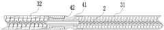
- the endoscopic surgical instrumentincludes: a handle 1, an operating wire 2, an outer tube 3, a rotating mechanism 4, and an action member 5.
- the handle 1is used to implement surgical actions, and may include a handle body, a slider, and an operating component.
- the inner core of the handle bodyis provided with a cavity to introduce the proximal end of the operating wire 2.
- the slidercan slide on the handle body, and the proximal end of the operating wire 2 is connected through the slider on the handle body, and the operating wire 2 is pulled to move, driving the action member 5 to open and close.
- the operating partscan be two rings set on the slider and a ring set on the end of the handle body. In actual applications, the two rings on the slider can be used to insert two fingers, such as index fingers and Middle finger; the ring on the end is used to insert the thumb to move the slider with the force of the fingers.
- the operating wire 2is connected to the handle 1 to transmit surgical actions.
- the operating wire 2is connected to the slider on the handle 1 to be able to transmit surgical actions.
- the operating wire 2can transmit a pulling force or a pushing force, so that the actuating member 5 generates a corresponding opening and closing action.
- the operating wire 2can also transmit a rotating torque, so that the action member 5 produces a corresponding rotating action.
- the length of the operating wire 2should ensure that it can extend from the patient's body to the body, and can also have different length specifications for different patients. Therefore, the operating wire 2 can be a steel wire rope wound from multiple strands of stainless steel wire, or a single wire, and the corresponding type should be selected according to actual needs.
- the outer tube 3includes a proximal tube 31 and a distal tube 32, and the operating wire 2 penetrates the inside of the proximal tube 31 and the distal tube 32.
- the outer tube 3has three functions. One is to guide the operating wire 2 into the patient's body; the other is to act as an operating component for rotating the operating wire 2; and the third is to transmit circumferential force and axial force. Therefore, the outer tube 3 has two parts, a proximal tube 31 and a distal tube 32.
- the proximal tube 31is located outside the patient's body during the actual operation, and the distal tube 32 extends into the patient's body.
- the proximal tube 31 and the distal tube 32can be made of plastic hoses of the same material, and a spirally extending support spring is arranged inside, so that the proximal tube 31 and the distal tube 32 can be squeezed by the sidewall tissue of the digestive tract. , Can still maintain the tubular state, avoid affecting the action of internal devices.
- the endoscopic surgical instrumentprovided by the present application can divide the distal part and the proximal part of the outer tube 3, namely the proximal tube 31 and the distal tube 32, so that the proximal end outside the endoscope
- the tube 31can generate a degree of freedom of rotation in the circumferential direction relative to the distal tube 32, and then transmits the rotational motion to the operating wire 2 in the central part of the instrument through the proximal end of the proximal tube 31, and further transmits it to the action part of the instrument head 5. Enable the action member 5 to rotate accurately.
- the rotating mechanism 4is used to connect the proximal tube 31 and the distal tube 32 so that the proximal tube 31 can rotate relative to the distal tube 32.
- the rotating mechanism 4plays a role of adapting, that is, the rotating mechanism 4 enables the proximal tube 31 and the distal tube 32 to rotate with each other while being connected to each other. Therefore, the actual During the operation, after the entire outer tube 3 is input into the patient's body, the proximal tube 31 located outside the body can be rotated to drive the operating wire 2 to rotate, so as to finally adjust the angle of the action member 5.
- one end of the proximal tube 31is rotatably connected to the handle 1, and the other end is fixedly connected to the end of the rotating mechanism 4;
- the inside of the rotating mechanism 4is slidably connected to the operating wire 2 so that the operating wire 2 rotates with the rotating mechanism 4 and moves within the rotating mechanism 4.
- the end of the handle 1can be provided with a sliding groove
- the proximal tube 31is provided with a protrusion corresponding to the shape of the sliding groove, so that the proximal tube 31 can be connected to the handle 1 The end position, and can rotate relative to the handle 1.
- the distal end of the proximal tube 31is fixedly connected to the rotating mechanism 4, and is connected to the operating wire 2 in the tube through the rotating mechanism 4.
- the rotational torque acting on the proximal tube 31can be transmitted to the rotating
- the mechanism 4is further transmitted to the operating wire 2 by the rotating mechanism 4, so that the operating wire 2 also rotates.
- the rotating mechanism 4can rotate relative to the distal tube 32, when the proximal tube 31 is rotated, the distal tube 32 remains stationary, that is, the rotation process will not be affected by the tissues in the patient's body. Will be affected by the clamp of the endoscopic equipment.
- the rotating mechanism 4 and the operating wire 2adopt a sliding connection, that is, the rotating mechanism 4 can drive the operating wire 2 to rotate, but the movement of the operating wire 2 will not be restricted by the rotating mechanism 4. Therefore, the technology provided in this application In the solution, the proximal tube 31 can be used to drive the operation wire 2 to rotate under the premise of ensuring that the operation movement transmitted by the operation wire 2 is not affected.
- the action member 5is arranged at the end of the distal tube 32 and connected to the operating wire 2.
- the action piece 5 provided in the present applicationmay also be different.
- the action piece 5may be one of a snare, a hemostatic clip, a biopsy forceps, a foreign body forceps, or a cutting knife.
- the present applicationcan also divide the distal part and the proximal part of the outer tube 3 of the instrument, and add a rotating mechanism 4 between the two, which is relative to the proximal tube 31 and the distal part.
- the end tube 32has a degree of freedom of rotation in the circumferential direction, and transmits the rotating motion to the operating wire 2 in the central part of the instrument, and further to the action member 5 at the distal end of the instrument, so that the action member 5 can rotate accurately. Therefore, the surgeon himself or his assistant can control the rotational movement of the action member 5 by rotating the proximal tube 31, which improves the convenience of instrument operation.
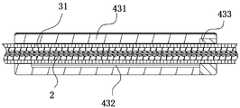
- the rotating mechanism 4includes a first follower 41 fixedly connected to the proximal tube 31, and a first special-shaped tube 42 that is wrapped and fixed on the outer surface of the operating wire 2;
- a follower 41is slidably connected to the first special-shaped tube 42 to transmit a rotational torque to the first special-shaped tube 42 and to enable the first special-shaped tube 42 to slide relative to the first follower 41.
- the first follower 41can be a cylindrical structure with a hole in the middle, so that the first follower 41 can extend from the end of the proximal tube 31 to the inside of the tube body.
- the first special-shaped tube 42can be sleeved on the outer surface of the operating wire 2 and fixed together, and can rotate or move together with the operating wire 2.
- the first follower 41 and the first special-shaped tube 42have a mutually matched structure to transmit a rotating torque.
- the first special-shaped tube 42may be a tube structure with strip-shaped protrusions on the outer wall
- the first follower 41is a tube-shaped structure with U-shaped grooves on the inner wall, and the strip-shaped protrusions and U-shaped recesses
- the restriction between the groove walls of the groovecan realize that the first follower 41 drives the first special-shaped tube 42 to rotate, and the strip-shaped protrusion and the U-shaped groove can also slide relatively along the groove. Therefore, The rotating torque can be transmitted to the operating wire 2 without affecting the movement of the operating wire 2.
- the connection between the rotating mechanism 4 and the operating wire 2is a key connection, that is, through a flat key, a wedge-shaped key spline, etc., the transmission is transmitted under the premise of ensuring mutual sliding.
- the cross-sectional shape of the first special-shaped tube 42can also be a regular or irregular shape such as a "back" shape, a rhombus or a polygon, and the corresponding first follower 41 also has a matching shape and structure, as long as it can transmit Both the torque of rotation and the mutual sliding can be used as technical solutions that can be adopted for the sliding connection of the present application.
- the first special-shaped tube 42needs to slide relative to the first follower 41, and the maximum sliding distance during the operation is often the same according to the farthest moving distance of the control slider on the handle, so in the part of this application
- the length of the first special-shaped tube 42is greater than or equal to the farthest moving distance of the control slider on the handle 1, that is, during the sliding of the control slider on the handle 1 from one end of the handle 1 to the other end, the first A follower 41 can also run from one end of the first special-shaped tube 42 to the other end, so that the first special-shaped tube 42 will not interact with the first follower 41 during the operation. Separation to ensure the smooth progress of the operation.
- the rotating mechanism 4further includes a driving member 43 fixedly connected to the outer wall of the proximal tube 31, so
- the driving member 43has a cylindrical structure, and the outer circumferential wall of the driving member 43 is provided with anti-skid patterns.
- the driving member 43may be a cylindrical structure sleeved on the outer wall of the proximal tube 31, which can be used for operation by the surgeon, and the cylindrical structure of the driving member 43 increases the moment arm during rotation, thereby Under the same rotating force, a larger rotating torque is produced.
- the anti-skid pattern on the driving member 43can also be used to reduce the slipping phenomenon during the rotation, thereby making the rotation process more accurate.
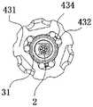
- the driving member 43includes a driving bag 431, a pin shaft 432 and a positioning cap 433.
- the driving capsule 431is a tubular structure sheathed on the proximal tube 31; the inner wall of the driving capsule 431 is provided with a receiving groove, and the pin 432 is arranged in the receiving groove of the driving capsule 431;
- the positioning cap 433is provided at the end of the driving capsule 431 to fix the pin 432 on the outer wall of the proximal tube 31.
- the driving capsule 431can be made of plastic or soft plastic material to improve the comfort of operation and increase the frictional force during the rotation process.
- the proximal end The tube 31can rotate with the driving bladder 431, that is, under the condition that the original structure of the proximal tube 31 is maintained, the cooperation between the driving member 43 and the proximal tube 31 is realized.
- the pin shaft 432 and the positioning cap 433also enable the driving bladder 431 to move on the proximal tube 31 while transmitting the rotational torque, thereby changing the position of the driving bladder 431 to adapt to the operating habits of different surgeons. .
- the positioning cap 433can be connected with the driving capsule 431 through a snap or latch structure, and has a certain elastic function to press the pin shaft 432 against the outer wall of the proximal tube 31 or produce a direction toward the outer wall of the proximal tube 31.
- the forceis shown in FIG. 5, the driving member 43 further includes a compression spring 434, two pin shafts 432 are arranged in one receiving groove of the driving bag 431, and the compression spring 434 is arranged in two Between the pin 432.
- a one-way bearing structurecan be formed inside the driving capsule 431, so that the driving capsule 431 can slide relative to the proximal tube 31, but cannot rotate relative to the proximal tube 31.
- the compression spring 434can also buffer the rotation torque and reduce the rotation delay. Make the rotation process more stable.
- the main function of the driving member 43is to perform a rotating operation. Therefore, in some embodiments of the present application, the driving member 43 and the first driven member 41 and/or the proximal end
- the tube 31is an integral structure. That is, in practical applications, the component structure can be simplified through the integrated structure, thereby improving the stability and reliability of the entire device.
- other structuresthat can be imagined in the field based on the above-mentioned features, such as the driving member 43 and the first follower 41, the driving member 43 and the proximal tube 31, or the driving member 43 and the first driven member 41 and the proximal end All the cases where the tubes 31 are of integral structure belong to the protection scope of this application.
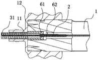
- the endoscopic surgical instrumentfurther includes a driven mechanism 6, and the proximal tube 31 is rotatably connected to the handle 1 through the driven mechanism 6.
- the driven mechanism 6includes a second driven member 61 and a second special-shaped tube 62; the second driven member 61 is fixedly connected to the proximal tube 31; the second driven member 61 is slidably connected to the first Two special-shaped tubes 62; The second special-shaped tubes 62 are fixedly connected to the outer surface of the operating wire 2.
- the driven mechanism 6may be similar in structure to the rotating mechanism 4 and have the same function, both of which are to realize mutual rotation between the proximal tube 31 and the adjacent components.
- the driven mechanism 6also includes a fixed cap 11 screwed on the end of the handle 1; the proximal tube 31 penetrates the inside of the fixed cap 11; the inner core of the handle 1 is provided with Cylindrical hole 12; the second follower 61 is disposed in the cylindrical hole 12 and can rotate in the cylindrical hole 12.
- the driven mechanism 6can be slidably connected with the operating wire 2 at the positions of the two ends of the proximal tube 31 on the premise that the proximal tube 31 can be rotated, which can also increase the torque transmission effect of the proximal tube 31 , So improve the transmission accuracy of the rotation action.
- the present applicationalso provides an endoscopic surgical instrument, as shown in FIG. 7, comprising: an operating wire 2 to transmit surgical actions; the outer tube 3 includes a proximal tube 31 and a distal tube 32, and the operating wire 2 penetrates the The inside of the proximal tube 31 and the distal tube 32; the rotating mechanism 4, which connects the proximal tube 31 and the distal tube 32; the action member 5, which is arranged at the distal end of the distal tube 32, and connects the operation Wire 2; wherein the proximal end of the rotating mechanism 4 is rotatably connected to the proximal tube 31, and the distal end of the rotating mechanism 4 is rotatably connected to the distal tube 32; the interior of the rotating mechanism 4 The operating wire 2 is slidably connected so that the operating wire 2 rotates with the rotating mechanism 4 and can move in the rotating mechanism 4.
- the proximal tube 31 and the distal tube 32may not rotate with each other, but the rotating mechanism 4 drives the operating wire 2 to rotate.
- the rotation mechanism 4is set at the position where the proximal tube 31 and the distal tube 32 connect, so that the rotation mechanism 4 is close to the opening position of the endoscope forceps, and the surgical operator can directly rotate the rotation mechanism 4 A rotating torque is applied to the operating wire 2, and finally the operating member 5 is controlled to perform a rotating operation.
- the principle of use of the endoscopic surgical instrumentis to clamp the wound of the stomach as an example, which may include: lower the endoscope for conventional wound closure surgery; take out an assembled endoscope
- For surgical instrumentslightly pull the slider of the handle 1 to close the distal action piece 5, namely the hemostatic clip, insert the hemostatic clip into the clamp channel of the endoscope and send it to the wound, and then push the handle slider to open the hemostatic clip.
- the hemostatic clipis in a non-ideal state at this time, the surgeon needs to quickly rotate the driver 43 or directly rotate the proximal tube 31 to drive the hemostatic clip mechanism to make a corresponding rotation.
- the assistantwill stop the bleeding. Release the clip and take out the other parts of the device from the endoscope.
- the devicecan be delivered as described above until the wound is completely closed.
- the manufacturing and assembly process of the endoscopic surgical instrumentsis simple and suitable for all kinds of instruments that require rotation, such as rotatable snares, rotatable hemostatic clamps, rotatable biopsy forceps or foreign body forceps, etc. medical instruments. And it allows the operator to rotate the proximal tube 31 autonomously to drive the operation wire 2 and the action piece 5 to rotate the distal mechanism, which reduces the coordination requirements between the operator and the assistant, shortens the operation time, and is accurate and efficient. The completion of the operation process reduces the patient’s pain and greatly reduces the risk of shock and even death caused by long-term bleeding.
Landscapes
- Health & Medical Sciences (AREA)
- Surgery (AREA)
- Life Sciences & Earth Sciences (AREA)
- Heart & Thoracic Surgery (AREA)
- Nuclear Medicine, Radiotherapy & Molecular Imaging (AREA)
- Engineering & Computer Science (AREA)
- Biomedical Technology (AREA)
- Medical Informatics (AREA)
- Molecular Biology (AREA)
- Animal Behavior & Ethology (AREA)
- General Health & Medical Sciences (AREA)
- Public Health (AREA)
- Veterinary Medicine (AREA)
- Vascular Medicine (AREA)
- Reproductive Health (AREA)
- Surgical Instruments (AREA)
Abstract
Description
Translated fromChinese本申请要求在2019年6月6日提交中国专利局、申请号为201910489341.2、发明名称为“一种内窥镜手术器械”的中国专利申请的优先权,其全部内容通过引用结合在本申请中。This application claims the priority of a Chinese patent application filed with the Chinese Patent Office, the application number is 201910489341.2, and the invention title is "an endoscopic surgical instrument" on June 6, 2019, the entire content of which is incorporated into this application by reference .
本申请涉及医疗器械技术领域,尤其涉及一种内窥镜手术器械。This application relates to the technical field of medical devices, and in particular to an endoscopic surgical instrument.
消化道器械是指能够进入患者的消化道,实施体内手术操作的器械,如圈套器、止血夹、活检钳或异物钳等。消化道器械在实际应用中,需要医生从体外操作,并通过操作丝传递操作动作,控制位于体内的器械实施手术动作。以止血夹为例,利用止血夹闭合时产生的机械力,可将其周围组织及出血血管一并结扎,从而闭合出血的血管,因此止血夹对于组织的结扎能力,直接影响手术质量。Digestive tract instruments refer to instruments that can enter the patient's digestive tract to perform internal surgical operations, such as snares, hemostatic clamps, biopsy forceps, or foreign body forceps. In practical applications, digestive tract instruments require doctors to operate from outside the body and transmit operating actions through operating wires to control the instruments in the body to perform surgical actions. Taking the hemostatic clip as an example, the mechanical force generated when the hemostatic clip is closed can ligate the surrounding tissues and blood vessels together, thereby closing the bleeding blood vessels. Therefore, the ability of the hemostatic clip to ligate tissues directly affects the quality of the operation.
为了进行有效操作,快速止血和预防再出血,典型的止血夹除具备夹闭功能外,大部分器械还同时具备旋转功能,以便使用时准确对准需要闭合的组织创面。典型的止血夹包括手柄、导管、操作丝以及夹持部。其中,手柄通过导管内部设置的操作丝连接夹持部,以通过手柄控制夹持部进行移动,手柄还与导管端部活动连接,即手柄可以相对于导管进行旋转,以在转动手柄时,带动夹持部进行转动。In order to perform effective operations, fast hemostasis and prevention of rebleeding, in addition to the clamping function, most of the hemostatic clamps also have the rotation function, so as to accurately align the tissue wound that needs to be closed during use. A typical hemostatic clip includes a handle, a catheter, an operating wire, and a clamping part. Among them, the handle is connected to the clamping part by an operating wire set inside the catheter to control the movement of the clamping part through the handle. The handle is also movably connected to the end of the catheter, that is, the handle can be rotated relative to the catheter to drive when the handle is turned. The clamping part rotates.
但上述止血夹在实际手术过程中,其旋转功能是通过手术实施人员的助手实施旋转操作,以带动操作丝转动,实现夹持部的旋转。因此,为了能够准确的夹闭血管或创面达到高效的治疗效率,需要手术实施者和助手之间进行密切的配合,但目前临床术者和助手的配合往往并不能达到完全理想的效果,故急需一种由术者控制旋转的止血夹来弥补现有器械的不足。However, in the actual operation process, the rotation function of the hemostatic clip is to perform a rotation operation by the assistant of the operator to drive the operation wire to rotate and realize the rotation of the clamping part. Therefore, in order to accurately clip blood vessels or wounds to achieve high-efficiency treatment efficiency, close cooperation between the operator and the assistant is required. However, the current cooperation between the clinical surgeon and the assistant often cannot achieve the complete ideal effect, so it is urgently needed A hemostatic clip whose rotation is controlled by the surgeon makes up for the shortcomings of the existing equipment.
发明内容Summary of the invention
本申请提供了一种内窥镜手术器械,以解决传统消化道器械实施旋转操作存在以上不足的问题。The present application provides an endoscopic surgical instrument to solve the above-mentioned shortcomings in the implementation of rotating operation of traditional digestive tract instruments.
一方面,本申请提供一种内窥镜手术器械,包括:操作丝、外管、旋转机构以及动作件,其中,所述操作丝连接手柄,以传递手术动作;外管包括近端管和远端管,所述操作丝贯穿所述近端管和远端管的内部;旋转机构,用于连接所述近端管和远端管,以使所述近端管可相对于所述远端管转动;动作件,设置在所述远端管的远端部,以及连接所述操作丝。In one aspect, the present application provides an endoscopic surgical instrument, including: an operating wire, an outer tube, a rotating mechanism, and an action member, wherein the operating wire is connected to a handle to transmit surgical actions; the outer tube includes a proximal tube and a distal tube End tube, the operating wire penetrates the inside of the proximal tube and the distal tube; a rotating mechanism for connecting the proximal tube and the distal tube, so that the proximal tube can be relative to the distal tube The tube rotates; the action piece is arranged at the distal end of the distal tube and is connected to the operating wire.
所述近端管的一端与所述手柄可转动地连接,另一端固定连接所述旋转机构的近端部;所述旋转机构的内部滑动连接所述操作丝,以使所述操作丝随着所述旋转机构转动,并且在所述旋转机构内移动。One end of the proximal tube is rotatably connected with the handle, and the other end is fixedly connected to the proximal end of the rotating mechanism; the inside of the rotating mechanism is slidably connected to the operating wire so that the operating wire follows The rotating mechanism rotates and moves within the rotating mechanism.
可选的,所述旋转机构包括固定连接所述近端管的第一从动件,以及包覆固定在 所述操作丝外表面上的第一异形管;Optionally, the rotating mechanism includes a first follower fixedly connected to the proximal tube, and a first special-shaped tube covered and fixed on the outer surface of the operating wire;
所述第一从动件滑动连接所述第一异形管,以向所述第一异形管传递转动力矩,以及使所述第一异形管可相对于所述第一从动件滑动。所述第一异形管的长度,大于或等于手柄上控制滑块的最远移动距离。The first follower is slidably connected to the first special-shaped tube, so as to transmit a rotating torque to the first special-shaped tube, and enable the first special-shaped tube to slide relative to the first follower. The length of the first special-shaped tube is greater than or equal to the farthest moving distance of the control slider on the handle.
可选的,所述旋转机构还包括连接在所述近端管外壁上的驱动件,该驱动件可沿近端管轴向滑动,但不能与近端管发生相互转动,所述驱动件为圆柱形结构,所述驱动件的外圆周壁上设有防滑纹。Optionally, the rotating mechanism further includes a driving member connected to the outer wall of the proximal tube, the driving member can slide axially along the proximal tube but cannot rotate with the proximal tube, and the driving member is Cylindrical structure, anti-skid patterns are provided on the outer circumferential wall of the driving member.
可选的,所述驱动件包括驱动囊、销轴和定位帽;Optionally, the driving member includes a driving bag, a pin shaft and a positioning cap;
所述驱动囊为套设在所述近端管上的管状结构;所述驱动囊的内壁设有容纳槽,所述销轴设置在所述驱动囊的容纳槽中;所述定位帽设置在所述驱动囊的端部,以使所述销轴固定在所述近端管的外壁上。The driving bladder is a tubular structure sheathed on the proximal tube; the inner wall of the driving bladder is provided with a receiving groove, and the pin shaft is provided in the receiving groove of the driving bladder; the positioning cap is provided in The end of the driving capsule is used to fix the pin on the outer wall of the proximal tube.
可选的,所述驱动件还包括压缩弹簧,所述驱动囊的一个容纳槽内设有两个所述销轴,所述压缩弹簧设置在两个所述销轴之间。Optionally, the driving member further includes a compression spring, two pin shafts are arranged in one accommodating groove of the driving bag, and the compression spring is arranged between the two pin shafts.
可选的,所述驱动件与第一从动件和/或近端管为一体式结构。Optionally, the driving part and the first follower and/or the proximal tube are an integral structure.
可选的,还包括从动机构,所述近端管通过所述从动机构可转动地连接所述手柄;Optionally, it further includes a driven mechanism through which the proximal tube is rotatably connected to the handle;
所述从动机构包括第二从动件和第二异形管;所述第二从动件固定连接所述近端管;所述第二从动件滑动连接所述第二异形管;所述第二异形管固定连接在所述操作丝的外表面。The driven mechanism includes a second follower and a second special-shaped tube; the second follower is fixedly connected to the proximal tube; the second follower is slidably connected to the second special-shaped tube; The second special-shaped tube is fixedly connected to the outer surface of the operating wire.
可选的,所述从动机构还包括螺接在所述手柄端部的固定帽;所述近端管贯穿所述固定帽的内部;所述手柄的内芯上设有圆柱孔;所述第二从动件设置在所述圆柱孔内,可在所述圆柱孔内转动。Optionally, the driven mechanism further includes a fixed cap screwed on the end of the handle; the proximal tube penetrates the inside of the fixed cap; the inner core of the handle is provided with a cylindrical hole; the The second follower is arranged in the cylindrical hole and can rotate in the cylindrical hole.
可选的,所述旋转机构与所述操作丝之间的连接方式为键连接。Optionally, the connection between the rotating mechanism and the operating wire is a key connection.
另一方面,本申请提供一种内窥镜手术器械,包括:操作丝、外管、旋转机构以及动作件,其中,操作丝用于传递手术动作;外管包括近端管和远端管,所述操作丝贯穿所述近端管和远端管的内部;旋转机构连接所述近端管和远端管;动作件设置在所述远端管的端部,以及连接所述操作丝。On the other hand, the present application provides an endoscopic surgical instrument, including: an operating wire, an outer tube, a rotating mechanism, and an action member, wherein the operating wire is used to transmit surgical actions; the outer tube includes a proximal tube and a distal tube, The operating wire penetrates the inside of the proximal tube and the distal tube; the rotating mechanism connects the proximal tube and the distal tube; the action member is arranged at the end of the distal tube and connects with the operating wire.
所述旋转机构的近端可转动地连接所述近端管,所述旋转机构的远端可转动地连接所述远端管;所述旋转机构的内部滑动连接所述操作丝,以使所述操作丝随着所述旋转机构转动,并且可在所述旋转机构内移动。The proximal end of the rotation mechanism is rotatably connected to the proximal tube, and the distal end of the rotation mechanism is rotatably connected to the distal tube; the inside of the rotation mechanism is slidably connected to the operating wire, so that the The operating wire rotates with the rotating mechanism and can move in the rotating mechanism.
由以上技术方案可知,本申请提供一种内窥镜手术器械,包括:操作丝、外管、旋转机构以及动作件。其中,所述外管进一步包括近端管和远端管,旋转机构设置在近端管和远端管之间。旋转机构的内部滑动连接操作丝,以使操作丝随着旋转机构转动,并且可在所述旋转机构内移动。实际应用中,通过转动近端管或者旋转机构带动操作丝转动,以调整动作件的角度,无需转动手柄方便操作。并且,可以由手术实施者直接操作近端管进行旋转,降低操作难度,有利于实施旋转操作。It can be seen from the above technical solutions that this application provides an endoscopic surgical instrument, which includes an operating wire, an outer tube, a rotating mechanism and an action piece. Wherein, the outer tube further includes a proximal tube and a distal tube, and the rotating mechanism is arranged between the proximal tube and the distal tube. The inner part of the rotating mechanism is slidably connected with the operating wire, so that the operating wire rotates with the rotating mechanism and can move in the rotating mechanism. In practical applications, the operating wire is driven to rotate by rotating the proximal tube or the rotating mechanism to adjust the angle of the moving part, without turning the handle for easy operation. In addition, the operator can directly operate the proximal tube for rotation, which reduces the difficulty of the operation and facilitates the implementation of the rotation operation.
为了更清楚地说明本申请的技术方案,下面将对实施例中所需要使用的附图作简单地介绍,显而易见地,对于本领域普通技术人员而言,在不付出创造性劳动的前提下,还可以根据这些附图获得其他的附图。In order to explain the technical solution of the present application more clearly, the following will briefly introduce the drawings needed in the embodiments. Obviously, for those of ordinary skill in the art, without creative work, Other drawings can be obtained from these drawings.
图1为本申请一种内窥镜手术器械的结构示意图;Figure 1 is a schematic structural diagram of an endoscopic surgical instrument of this application;
图2为本申请一种旋转机构的结构示意图;Figure 2 is a schematic structural diagram of a rotating mechanism of this application;
图3为本申请驱动件的剖视结构示意图;Figure 3 is a schematic cross-sectional structure diagram of the driving element of the application;
图4为本申请一种驱动件的侧视结构示意图;Fig. 4 is a schematic side view of the structure of a driving element of the application;
图5为本申请另一种驱动件的侧视结构示意图;Figure 5 is a schematic side view of another driving element of the application;
图6为本申请从动机构的结构示意图;Figure 6 is a schematic diagram of the structure of the driven mechanism of the application;
图7为本申请另一种内窥镜手术器械的结构示意图。Fig. 7 is a schematic structural diagram of another endoscopic surgical instrument of this application.
下面将详细地对实施例进行说明,其示例表示在附图中。下面的描述涉及附图时,除非另有表示,不同附图中的相同数字表示相同或相似的要素。以下实施例中描述的实施方式并不代表与本申请相一致的所有实施方式。仅是与权利要求书中所详述的、本申请的一些方面相一致的系统和方法的示例。The embodiments will be described in detail below, and examples thereof are shown in the accompanying drawings. When the following description refers to the drawings, unless otherwise indicated, the same numbers in different drawings indicate the same or similar elements. The implementation manners described in the following examples do not represent all implementation manners consistent with this application. These are just examples of systems and methods that are consistent with some aspects of the application as detailed in the claims.
本申请提供的技术方案中,为了便于描述,将整个装置置入人体内的一端称为远端,这一端主要用于对组织实施手术动作;位于体外的一端称为近端,这一端主要用于手术实施者进行操作。本申请除另有说明外,各部件所称的远端都是靠近体内一侧的一端,各部件所称的近端都是指靠近体外一侧的一端。In the technical solution provided in this application, for ease of description, the end of the entire device placed in the human body is called the distal end, and this end is mainly used to perform surgical actions on the tissue; the end outside the body is called the proximal end, and this end is mainly used Operate by the operator. Unless otherwise specified in this application, the distal end of each component refers to the end close to the internal body, and the proximal end of each component refers to the end close to the external body.
参见图1,为本申请一种内窥镜手术器械的结构示意图。Refer to Fig. 1, which is a schematic structural diagram of an endoscopic surgical instrument of this application.
如图1、图2所示,本申请提供的内窥镜手术器械,包括:手柄1、操作丝2、外管3、旋转机构4以及动作件5。其中,手柄1用于实施手术动作,可以包括手柄主体、滑块以及操作部件。手柄主体内芯设有空腔,以引入操作丝2的近端。滑块可以在手柄主体上滑动,并且通过手柄主体上的滑块连接操作丝2的近端,以牵引操作丝2进行移动,驱使动作件5开启和闭合。操作部件可以为设置在滑块上的两个圆环,以及设置在手柄主体末端上的圆环,实际应用中,滑块上的两个圆环可以分别用于插入两个手指,如食指和中指;末端上的圆环用于插入拇指,以通过手指捏合的力量移动滑块。As shown in FIGS. 1 and 2, the endoscopic surgical instrument provided by the present application includes: a
操作丝2连接所述手柄1,以传递手术动作。本申请提供的技术方案中,操作丝2连接手柄1上的滑块,以能够传递手术动作。例如,手术实施者调整手柄1上的滑块位置时,操作丝2能够传递拉力或推力,以使动作件5产生对应的开闭动作。另外,操作丝2还能够传递转动力矩,以使动作件5产生对应的转动动作。操作丝2的长度应保证能够从患者的体外延伸至体内,并且针对不同的患者,还可以拥有不同的长度规格。因此,操作丝2可以是多股不锈钢丝绕制而成的钢丝绳,也可以是单丝,应根据实际需要进行对应的类型选择。The
如图2所示,外管3包括近端管31和远端管32,所述操作丝2贯穿所述近端管31和远端管32的内部。本申请提供的技术方案中,外管3具有三个作用,其一为引导操作丝2进入患者体内;其二作为旋转操作丝2的操作部件;其三用于传递周向力和轴向力。因此,外管3具有近端管31和远端管32两个部分,其中,近端管31在实际手术过程中,位于患者的体外部分,远端管32延伸到患者的体内。近端管31和远端管32可以为材质相同的塑料软管,并且其内部设有螺旋延伸的支撑弹簧,使近端管31和远端管32在受到消化道侧壁组织的挤压时,仍然能够保持管状状态,避免影响 到内部器件的动作。As shown in FIG. 2, the outer tube 3 includes a
由以上技术方案可知,本申请提供的内窥镜手术器械可以将外管3的远端部分与近端部分进行分割,即近端管31和远端管32,使处于内镜外的近端管31可以相对于远端管32在圆周方向产生旋转的自由度,进而通过近端管31的近端将旋转运动传递给器械中心部分的操作丝2,并进一步传递给器械头部的动作件5,使动作件5能够精确的旋转。It can be seen from the above technical solutions that the endoscopic surgical instrument provided by the present application can divide the distal part and the proximal part of the outer tube 3, namely the
如图2、图3所示,旋转机构4用于连接所述近端管31和远端管32,以使所述近端管31可相对于所述远端管32转动。本申请提供的技术方案中,旋转机构4起到转接作用,即通过旋转机构4可以使得近端管31和远端管32在相互连接的同时,还能够相互之间发生转动,因此,实际手术中,可以在整个外管3输入患者的体内后,通过旋转位于体外的近端管31,带动操作丝2进行旋转,以最终调整动作件5的角度。As shown in FIGS. 2 and 3, the
为了实现上述功能,本申请提供的技术方案中,如图2所示,所述近端管31的一端与所述手柄1可转动地连接,另一端固定连接所述旋转机构4的端部;所述旋转机构4的内部滑动连接所述操作丝2,以使所述操作丝2随着所述旋转机构4转动,并且在所述旋转机构4内移动。实际应用时,如图1所示,手柄1的端部可以设置有滑槽,近端管31的内部设有与滑槽对应形状的凸起,以使近端管31可以连接在手柄1的端部位置,并且相对于手柄1可以转动。近端管31的远端固定连接旋转机构4,并通过所述旋转机构4连接管内的操作丝2,当旋转近端管31时,作用在近端管31上的转动力矩可以被传递到旋转机构4上,并由旋转机构4进一步传递给操作丝2,以使操作丝2也发生转动。In order to achieve the above functions, in the technical solution provided by the present application, as shown in FIG. 2, one end of the
本申请中,由于旋转机构4可以相对于远端管32发生转动,因此在转动近端管31时,远端管32是保持不动的,即旋转过程不会受到患者体内组织影响,也不会受到内镜设备的钳道影响。另外,由于旋转机构4与操作丝2之间采用滑动连接,即旋转机构4可以带动操作丝2进行转动,但操作丝2的移动不会受到旋转机构4的限制,因此,本申请提供的技术方案中,可以在保证操作丝2传递手术动作不受影响的前提下,能够实现通过近端管31带动其进行转动。In the present application, since the
动作件5,设置在所述远端管32的端部,以及连接所述操作丝2。根据实际应用的手术不同,本申请提供的动作件5也可以不同,例如,所述动作件5可以是圈套器、止血夹、活检钳、异物钳或者切割刀中的一种。The action member 5 is arranged at the end of the
由以上技术方案可知,本申请还可以将器械外管3的远端部分与近端部分进行分割,并在两者之间增加一旋转机构4,此旋转机构4相对于近端管31和远端管32在圆周方向有旋转的自由度,并将旋转的运动传递给器械中心部分的操作丝2,并进一步传递给器械远端的动作件5,从而使动作件5能够精确的旋转。因此,手术实施者自身或助手都可以通过旋转近端管31来控制动作件5的旋转运动,提高器械操作的便利性。It can be seen from the above technical solutions that the present application can also divide the distal part and the proximal part of the outer tube 3 of the instrument, and add a
为了实现上述功能,所述旋转机构4包括固定连接所述近端管31的第一从动件41,以及包覆固定在所述操作丝2外表面上的第一异形管42;所述第一从动件41滑动连接所述第一异形管42,以向所述第一异形管42传递转动力矩,以及使所述第一异形管42可相对于所述第一从动件41滑动。In order to achieve the above-mentioned functions, the
实际应用中,第一从动件41可以是中部设有孔的圆柱形结构,使得第一从动件41可以从近端管31的端部向管体内部延伸。第一异形管42可以套设在操作丝2的外表面,并且固定在一起,可与操作丝2一同旋转或移动。第一从动件41和第一异形管42之间具有相互配合的结构,以传递转动力矩。例如,第一异形管42可以为外壁上设有条形凸起的管结构,而第一从动件41为内壁上设有U形槽的管状结构,并且通过条形凸起与U形凹槽的槽壁之间的限制作用,可以实现第一从动件41带动第一异形管42进行转动,并且条形凸起与U形凹槽之间还可以沿凹槽进行相对滑动,因此,可以在不影响操作丝2移动的前提下,向操作丝2传递转动力矩。In practical applications, the
在本申请的部分实施例中,所述旋转机构4与所述操作丝2之间的连接方式为键连接,即通过平键、楔形键花键等方式,在保证能够相互滑动的前提下传递转动力矩。进一步地,第一异形管42的截面形状还可以是“回”字形,菱形或多边形等规则或不规则形状,相应的第一从动件41也具有与之配合的形状结构,只要其能够传递转动力矩,并且保证相互滑动,都可以作为本申请滑动连接所能够采用的技术方案。In some embodiments of the present application, the connection between the
由于实际应用中,第一异形管42需相对于第一从动件41产生滑动,而手术过程中最大的滑动距离往往根据手柄上控制滑块的最远移动距离相同,因此在本申请的部分实施例中,所述第一异形管42的长度,大于或等于手柄1上控制滑块的最远移动距离,即手柄1上控制滑块从手柄1的一端滑动到另一端的过程中,第一从动件41也能够满足从第一异形管42的一端运行到另一端,以使第一异形管42在手术过程中,不会因为手术动作而与第一从动件41之间产生相互分离,保证手术过程的顺利进行。In practical applications, the first special-shaped
为了便于对近端管31实施转动动作,在本申请的部分实施例中,如图3所示,所述旋转机构4还包括固定连接在所述近端管31外壁上的驱动件43,所述驱动件43为圆柱形结构,所述驱动件43的外圆周壁上设有防滑纹。本实施例中,驱动件43可以是套设在近端管31外壁上的圆柱形结构,可以用于手术实施者操作,并且通过驱动件43的圆柱形结构增加旋转过程中的力臂,从而在相同的转动力的作用下,产生更大的转动力矩。另外,还可以通过驱动件43上的防滑纹,减少转动过程中的打滑现象,从而使转动过程更加精准。In order to facilitate the implementation of a rotating action on the
进一步地,如图4所示,所述驱动件43包括驱动囊431、销轴432和定位帽433。所述驱动囊431为套设在所述近端管31上的管状结构;所述驱动囊431的内壁设有容纳槽,所述销轴432设置在所述驱动囊431的容纳槽中;所述定位帽433设置在所述驱动囊431的端部,以使所述销轴432固定在所述近端管31的外壁上。Further, as shown in FIG. 4, the driving
本实施例中,驱动囊431可以采用塑料或软质塑胶材料制成,以提高操作的舒适度和增大转动过程的摩擦力,通过销轴432以及定位帽433的相互作用,可以使近端管31能够随着驱动囊431进行转动,即在保持近端管31原本结构的情况下,实现驱动件43与近端管31之间的配合。同时,通过销轴432和定位帽433还能够使驱动囊431可以在传递转动力矩的同时,在近端管31上窜动,从而改变驱动囊431的位置,以适应不同手术实施者的操作习惯。In this embodiment, the driving
实际应用中,定位帽433可以与驱动囊431之间通过卡扣或插销结构实现连接,并具有一定的弹性功能以将销轴432压紧近端管31的外壁或产生向近端管31外壁的作用力。进一步地,如图5所示,所述驱动件43还包括压缩弹簧434,所述驱动囊431 的一个容纳槽内设有两个所述销轴432,所述压缩弹簧434设置在两个所述销轴432之间。通过压缩弹簧434可以在驱动囊431的内部形成单向轴承结构,使驱动囊431可以相对于近端管31滑动,但不能相对于近端管31转动。另外,压缩弹簧434还可以缓冲旋转力矩,降低旋转的延时。使转动过程更加平稳。In practical applications, the
需要说明的是,由于在本申请中,驱动件43的主要作用是进行实施旋转操作,因此在本申请的部分实施例中,所述驱动件43与第一从动件41和/或近端管31为一体式结构。即在实际应用中,可以通过一体式结构简化部件结构,从而提高整个器械的稳定性和可靠性。另外,本领域基于上述特征所能够联想到的其他结构,如驱动件43与第一从动件41、驱动件43与近端管31、或者驱动件43与第一从动件41和近端管31均为一体式结构的情况,都属于本申请的保护范围。It should be noted that in this application, the main function of the driving
在本申请的部分实施例中,如图6所示,所述内窥镜手术器械还包括从动机构6,所述近端管31通过所述从动机构6可转动地连接所述手柄1。所述从动机构6包括第二从动件61、第二异形管62;所述第二从动件61固定连接所述近端管31;所述第二从动件61滑动连接所述第二异形管62;所述第二异形管62固定连接在所述操作丝2的外表面。本实施例中,从动机构6可以与旋转机构4的结构相似,并且作用相同,都是实现近端管31与相邻部件之间可以相互转动。In some embodiments of the present application, as shown in FIG. 6, the endoscopic surgical instrument further includes a driven
进一步的,所述从动机构6还包括螺接在所述手柄1端部的固定帽11;所述近端管31贯穿所述固定帽11的内部;所述手柄1的内芯上设有圆柱孔12;所述第二从动件61设置在所述圆柱孔12内,可在所述圆柱孔12内转动。实际应用中,从动机构6可以在实现近端管31可转动的前提下,通过在近端管31两端的位置上与操作丝2滑动连接,还可以增加近端管31对扭矩的传递作用,因此提高转动动作的传递精度。Further, the driven
本申请还提供一种内窥镜手术器械,如图7所示,包括:操作丝2以传递手术动作;外管3包括近端管31和远端管32,所述操作丝2贯穿所述近端管31和远端管32的内部;旋转机构4,连接所述近端管31和远端管32;动作件5,设置在所述远端管32的远端,以及连接所述操作丝2;其中,所述旋转机构4的近端可转动地连接所述近端管31,所述旋转机构4的远端可转动地连接所述远端管32;所述旋转机构4的内部滑动连接所述操作丝2,以使所述操作丝2随着所述旋转机构4转动,并且可在所述旋转机构4内移动。The present application also provides an endoscopic surgical instrument, as shown in FIG. 7, comprising: an operating
本实施例中,近端管31和远端管32之间可以不产生相互转动,而是通过旋转机构4带动操作丝2进行旋转。实际使用时,旋转机构4设置在近端管31和远端管32连接处的位置,以使得旋转机构4靠近内窥镜钳道的开口位置附近,手术操作人员可以直接通过转动旋转机构4来对操作丝2施加旋转力矩,最终控制动作件5进行旋转操作。In this embodiment, the
在本申请提供的技术方案中,所述内窥镜手术器械的使用原理以夹闭胃部创面为例,可以包括:下内窥镜进行常规创面闭合手术;取出一把已经装配完毕的内窥镜手术器械,轻拉手柄1的滑块闭合远端的动作件5,即止血夹,将止血夹穿入内窥镜钳道送至创面处,再推动手柄滑块打开止血夹。如果此时止血夹处于非理想状态需由手术实施者迅速转动驱动件43或者直接转动近端管31,从而带动止血夹机构做相应的旋转运动,当旋转至合适的位置时再由助手将止血夹释放,将装置其他零件从内窥镜 取出即可。实际应用中,根据创面需要可以按照如上步骤继续输送此装置直至创面完全闭合。In the technical solution provided by this application, the principle of use of the endoscopic surgical instrument is to clamp the wound of the stomach as an example, which may include: lower the endoscope for conventional wound closure surgery; take out an assembled endoscope For surgical instruments, lightly pull the slider of the
由以上技术方案可知,本申请提供的内窥镜手术器械的制作及装配工艺简单,适用于各类需要旋转的器械,如可旋转圈套器,可旋转止血夹,可旋转活检钳或异物钳等医疗器械。并且让手术实施者能够自主旋转近端管31而带动操作丝2和动作件5等远端机构旋转,使手术实施者和助手之间的配合度要求得到了降低,缩短了手术时间,准确高效的完成手术过程,减少病人痛苦,大大降低了患者因长时间出血导致的休克甚至死亡等风险。It can be seen from the above technical solutions that the manufacturing and assembly process of the endoscopic surgical instruments provided by this application is simple and suitable for all kinds of instruments that require rotation, such as rotatable snares, rotatable hemostatic clamps, rotatable biopsy forceps or foreign body forceps, etc. medical instruments. And it allows the operator to rotate the
本申请提供的实施例之间的相似部分相互参见即可,以上提供的具体实施方式只是本申请总的构思下的几个示例,并不构成本申请保护范围的限定。对于本领域的技术人员而言,在不付出创造性劳动的前提下依据本申请方案所扩展出的任何其他实施方式都属于本申请的保护范围。The similar parts between the embodiments provided in this application can be referred to each other. The specific implementations provided above are only a few examples under the general concept of this application, and do not constitute a limitation of the protection scope of this application. For those skilled in the art, any other implementation manners expanded according to the scheme of this application without creative work shall fall within the protection scope of this application.
Claims (10)
Translated fromChineseApplications Claiming Priority (2)
| Application Number | Priority Date | Filing Date | Title |
|---|---|---|---|
| CN201910489341.2ACN110051391B (en) | 2019-06-06 | 2019-06-06 | Endoscopic surgical instrument |
| CN201910489341.2 | 2019-06-06 |
Publications (1)
| Publication Number | Publication Date |
|---|---|
| WO2020244267A1true WO2020244267A1 (en) | 2020-12-10 |
Family
ID=67325644
Family Applications (1)
| Application Number | Title | Priority Date | Filing Date |
|---|---|---|---|
| PCT/CN2020/078454CeasedWO2020244267A1 (en) | 2019-06-06 | 2020-03-09 | Endoscopic surgical instrument |
Country Status (2)
| Country | Link |
|---|---|
| CN (1) | CN110051391B (en) |
| WO (1) | WO2020244267A1 (en) |
Families Citing this family (2)
| Publication number | Priority date | Publication date | Assignee | Title |
|---|---|---|---|---|
| CN110051391B (en)* | 2019-06-06 | 2024-03-26 | 南微医学科技股份有限公司 | Endoscopic surgical instrument |
| CN113812999B (en)* | 2021-08-30 | 2023-03-14 | 勾善淼 | Clamp system based on elastic metal |
Citations (8)
| Publication number | Priority date | Publication date | Assignee | Title |
|---|---|---|---|---|
| CN102357042A (en)* | 2011-10-20 | 2012-02-22 | 杭州康基医疗器械有限公司 | Multifunctional surgical clamp for endoscope |
| CN103989500A (en)* | 2014-05-23 | 2014-08-20 | 南京微创医学科技有限公司 | Hemostatic clip |
| CN104116534A (en)* | 2013-04-24 | 2014-10-29 | 德普伊米特克有限责任公司 | Devices, systems, and methods for suture management |
| CN105943095A (en)* | 2016-05-11 | 2016-09-21 | 天津大学 | Minimally invasive surgical instrument with flexible wrist part |
| US20180132923A1 (en)* | 2016-11-16 | 2018-05-17 | Boston Scientific Scimed, Inc. | Rotatable snares and related methods |
| US20180168679A1 (en)* | 2016-12-16 | 2018-06-21 | Hyung Jong Oh | Surgical snare instrument |
| CN108837280A (en)* | 2017-04-25 | 2018-11-20 | 韦伯斯特生物官能(以色列)有限公司 | Seal wire executor |
| CN110051391A (en)* | 2019-06-06 | 2019-07-26 | 南京微创医学科技股份有限公司 | A kind of endoscope operation instruments |
Family Cites Families (17)
| Publication number | Priority date | Publication date | Assignee | Title |
|---|---|---|---|---|
| US6235026B1 (en)* | 1999-08-06 | 2001-05-22 | Scimed Life Systems, Inc. | Polypectomy snare instrument |
| DE10064623C1 (en)* | 2000-12-22 | 2002-08-22 | Winter & Ibe Olympus | Endoscopic surgery forceps |
| AU2006200729A1 (en)* | 2001-05-02 | 2006-03-16 | Novare Surgical Systems, Inc. | Shaft for use with a clamp device |
| US20070255289A1 (en)* | 2006-04-27 | 2007-11-01 | Granit Medical Innovation, Inc. | Endoscopic instrument with rotational and axial motion control |
| JP5481194B2 (en)* | 2006-10-05 | 2014-04-23 | コヴィディエン リミテッド パートナーシップ | Flexible endoscopic suturing device |
| CA2592766A1 (en)* | 2007-06-29 | 2008-12-29 | Origin Medsystems, Inc. | Endoscopic vessel harvesting system components |
| CN201481494U (en)* | 2009-08-27 | 2010-05-26 | 安瑞医疗器械(杭州)有限公司 | a rotary snare |
| CN201524110U (en)* | 2009-11-09 | 2010-07-14 | 安瑞医疗器械(杭州)有限公司 | A rotary hemostatic clip |
| CN201631313U (en)* | 2010-03-10 | 2010-11-17 | 安瑞医疗器械(杭州)有限公司 | An endoscope grasping forceps |
| CN204581462U (en)* | 2015-04-14 | 2015-08-26 | 常州市久虹医疗器械有限公司 | A kind of rotatable net type foreign body forceps |
| JP6663992B2 (en)* | 2016-07-11 | 2020-03-13 | オリンパス株式会社 | Endoscope treatment tool |
| CN106491176A (en)* | 2016-11-15 | 2017-03-15 | 浙江创想医学科技有限公司 | One kind is rotatable to be repeated to be opened and closed hemostatic clamp |
| CN106983539B (en)* | 2017-05-08 | 2020-05-19 | 南微医学科技股份有限公司 | Medical rotatable snare |
| CN109381243B (en)* | 2017-08-02 | 2024-02-13 | 上海市嘉定区安亭医院 | Vascular forceps with electrocoagulation function for digestive endoscopic surgery |
| CN109833074A (en)* | 2019-02-20 | 2019-06-04 | 江苏格里特医疗科技有限公司 | A kind of rotatable hemostatic clamp |
| CN109805977B (en)* | 2019-03-21 | 2024-03-05 | 南微医学科技股份有限公司 | Medical hemostatic clamp |
| CN210631250U (en)* | 2019-06-06 | 2020-05-29 | 南微医学科技股份有限公司 | Endoscopic surgical instrument |
- 2019
- 2019-06-06CNCN201910489341.2Apatent/CN110051391B/enactiveActive
- 2020
- 2020-03-09WOPCT/CN2020/078454patent/WO2020244267A1/ennot_activeCeased
Patent Citations (8)
| Publication number | Priority date | Publication date | Assignee | Title |
|---|---|---|---|---|
| CN102357042A (en)* | 2011-10-20 | 2012-02-22 | 杭州康基医疗器械有限公司 | Multifunctional surgical clamp for endoscope |
| CN104116534A (en)* | 2013-04-24 | 2014-10-29 | 德普伊米特克有限责任公司 | Devices, systems, and methods for suture management |
| CN103989500A (en)* | 2014-05-23 | 2014-08-20 | 南京微创医学科技有限公司 | Hemostatic clip |
| CN105943095A (en)* | 2016-05-11 | 2016-09-21 | 天津大学 | Minimally invasive surgical instrument with flexible wrist part |
| US20180132923A1 (en)* | 2016-11-16 | 2018-05-17 | Boston Scientific Scimed, Inc. | Rotatable snares and related methods |
| US20180168679A1 (en)* | 2016-12-16 | 2018-06-21 | Hyung Jong Oh | Surgical snare instrument |
| CN108837280A (en)* | 2017-04-25 | 2018-11-20 | 韦伯斯特生物官能(以色列)有限公司 | Seal wire executor |
| CN110051391A (en)* | 2019-06-06 | 2019-07-26 | 南京微创医学科技股份有限公司 | A kind of endoscope operation instruments |
Also Published As
| Publication number | Publication date |
|---|---|
| CN110051391A (en) | 2019-07-26 |
| CN110051391B (en) | 2024-03-26 |
Similar Documents
| Publication | Publication Date | Title |
|---|---|---|
| US12121254B2 (en) | Slide slot type multi-arm clamp | |
| US20250127606A1 (en) | Systems and methods for performing endoscopic procedures | |
| CN110292411B (en) | Tissue clamping device | |
| CN103228223B (en) | Medical device with detachable pivotable jaws | |
| CA2168968C (en) | Medical device with improved actuating handle | |
| US5984939A (en) | Multifunctional grasping instrument with cutting member and operating channel for use in endoscopic and non-endoscopic procedures | |
| EP2147638B1 (en) | Endoscopically inserting surgical tool | |
| JP2019516421A (en) | Control device for a surgical instrument | |
| CN102762157A (en) | Medical devices with detachable pivotable jaws | |
| JP2012200415A (en) | Treatment instrument for endoscope | |
| CN115363649B (en) | A kind of flexible surgical instrument and instrument driving device thereof | |
| CN209518898U (en) | A kind of rotatable hemostatic clamp of Microendoscopic | |
| CN115363648B (en) | Flexible surgical instrument, flexible instrument and instrument conveying unit thereof | |
| CN114795395B (en) | Pliers, suction assembly and suction pliers having the same | |
| WO2020248807A1 (en) | Endoluminal surgery instrument | |
| JP2020526346A (en) | A device that assists in the positioning and fixation of the endoscope in gastrointestinal procedures | |
| WO2020244267A1 (en) | Endoscopic surgical instrument | |
| CN117860179A (en) | Multi-forceps endoscope and surgical system | |
| RU2503421C2 (en) | Selective displacement of handle | |
| CN210631250U (en) | Endoscopic surgical instrument | |
| CN210277289U (en) | Chute type multi-arm clamp | |
| US6162207A (en) | Operating unit for endoscopic treatment tool | |
| CN204181688U (en) | A kind of multiple degrees of freedom laparoscopic surgical instruments | |
| CN211187365U (en) | Biopsy sampling suction forceps | |
| WO2023041011A1 (en) | Clip instrument |
Legal Events
| Date | Code | Title | Description |
|---|---|---|---|
| 121 | Ep: the epo has been informed by wipo that ep was designated in this application | Ref document number:20819517 Country of ref document:EP Kind code of ref document:A1 | |
| NENP | Non-entry into the national phase | Ref country code:DE | |
| 122 | Ep: pct application non-entry in european phase | Ref document number:20819517 Country of ref document:EP Kind code of ref document:A1 |