WO2020218404A1 - Catheter and flexible endoscope comprising same - Google Patents
Catheter and flexible endoscope comprising sameDownload PDFInfo
- Publication number
- WO2020218404A1 WO2020218404A1PCT/JP2020/017458JP2020017458WWO2020218404A1WO 2020218404 A1WO2020218404 A1WO 2020218404A1JP 2020017458 WJP2020017458 WJP 2020017458WWO 2020218404 A1WO2020218404 A1WO 2020218404A1
- Authority
- WO
- WIPO (PCT)
- Prior art keywords
- catheter
- reinforcing pipe
- light guide
- guide
- image
- Prior art date
- Legal status (The legal status is an assumption and is not a legal conclusion. Google has not performed a legal analysis and makes no representation as to the accuracy of the status listed.)
- Ceased
Links
Images


Classifications
- A—HUMAN NECESSITIES
- A61—MEDICAL OR VETERINARY SCIENCE; HYGIENE
- A61B—DIAGNOSIS; SURGERY; IDENTIFICATION
- A61B1/00—Instruments for performing medical examinations of the interior of cavities or tubes of the body by visual or photographical inspection, e.g. endoscopes; Illuminating arrangements therefor
- A61B1/005—Flexible endoscopes
- A—HUMAN NECESSITIES
- A61—MEDICAL OR VETERINARY SCIENCE; HYGIENE
- A61B—DIAGNOSIS; SURGERY; IDENTIFICATION
- A61B1/00—Instruments for performing medical examinations of the interior of cavities or tubes of the body by visual or photographical inspection, e.g. endoscopes; Illuminating arrangements therefor
- A61B1/06—Instruments for performing medical examinations of the interior of cavities or tubes of the body by visual or photographical inspection, e.g. endoscopes; Illuminating arrangements therefor with illuminating arrangements
- A61B1/07—Instruments for performing medical examinations of the interior of cavities or tubes of the body by visual or photographical inspection, e.g. endoscopes; Illuminating arrangements therefor with illuminating arrangements using light-conductive means, e.g. optical fibres
- A—HUMAN NECESSITIES
- A61—MEDICAL OR VETERINARY SCIENCE; HYGIENE
- A61B—DIAGNOSIS; SURGERY; IDENTIFICATION
- A61B1/00—Instruments for performing medical examinations of the interior of cavities or tubes of the body by visual or photographical inspection, e.g. endoscopes; Illuminating arrangements therefor
- A61B1/313—Instruments for performing medical examinations of the interior of cavities or tubes of the body by visual or photographical inspection, e.g. endoscopes; Illuminating arrangements therefor for introducing through surgical openings, e.g. laparoscopes
- G—PHYSICS
- G02—OPTICS
- G02B—OPTICAL ELEMENTS, SYSTEMS OR APPARATUS
- G02B23/00—Telescopes, e.g. binoculars; Periscopes; Instruments for viewing the inside of hollow bodies; Viewfinders; Optical aiming or sighting devices
- G02B23/24—Instruments or systems for viewing the inside of hollow bodies, e.g. fibrescopes
- G02B23/26—Instruments or systems for viewing the inside of hollow bodies, e.g. fibrescopes using light guides
Definitions
- the present inventionrelates to a catheter and a flexible endoscope including the catheter, and more particularly to a catheter having improved operability and operability in a lumen and a flexible endoscope including the catheter.
- a flexible endoscopecalled an angioscope or an endoscopic catheter is used to measure the properties, length, and / or degree of stenosis of a lesion inside a blood vessel such as a coronary artery.
- a vascular endoscopeis designed to have a long axis and an extremely small shaft diameter in order to facilitate forward and backward movement in the blood vessel as compared with a gastrointestinal endoscope used for diagnosis, surgery, etc. of the gastrointestinal tract, for example. Has been done.
- the ride guideis composed of a glass fiber capable of irradiating the outside with light from the distal end (that is, the tip of the endoscope on the side farthest from the doctor's hand).
- the image guideis composed of an image fiber for image transmission for transmitting the image information obtained at the distal end to the doctor side.
- these two guidesare connected to the repeater device at the proximal end (that is, the tip of the endoscope closest to the doctor's hand).
- the repeater deviceis also electrically connected to a medical console equipped with various information processing functions for displaying, analyzing, storing, and the like transmitted image information.
- catheterthe catheter part (hereinafter, simply referred to as "catheter") that advances and retracts in the blood vessel is minimally invasive to the blood vessel. Further, in order to prevent damage in the blood vessel and to allow the catheter to flex freely in the branched and narrowly intricate blood vessel in the body, it is desired that the catheter has sufficient flexibility.
- the catheteris advanced, for example, by puncturing a predetermined part of the patient's body, from which the doctor grasps the catheter and pushes it into the blood vessel, but if the catheter is too soft, the doctor pushes it with a given force.
- the force based on the catheter's pushability, trackability, and crossability within the vesselis axially buffered by the flexibility of the catheter, resulting in distality. This is because fine operation at the edge may be difficult.
- An object of the present inventionis to solve the above problems, and an object thereof is to improve pushability, followability, and passability at the proximal end, and to provide appropriate flexibility at the distal end.
- the present inventionis a catheter comprising a flexible tube, an image guide, a light guide, and a reinforcing pipe.
- the flexible tubesurrounds the image guide, the light guide and the reinforcing pipe.
- the reinforcing pipehas a plurality of slits arranged along the long axis direction.
- the plurality of slitsis composed of at least one spiral slit or a plurality of arcuate slits provided continuously or intermittently along the outer circumference of the reinforcing pipe, and the length of the reinforcing pipe.
- a catheter in which the distance between two adjacent slits in the axial directionis longer on the proximal side than on the distal side of the catheter.
- the image guideis arranged inside the reinforcing pipe.
- the light guideis composed of a plurality of glass fibers, and the light guide is arranged outside the reinforcing pipe.
- the reinforcing pipeis arranged between the image guide and the light guide, whereby the image guide and the light guide are spatially separated.
- the distal end of the reinforcing pipeis located proximal to each of the distal ends of the flexible tube, the image guide and the light guide.
- the distal end of the reinforcing pipeis not fixed to any of the flexible tube, the image guide, and the light guide.
- the distance between the two adjacent slitsextends continuously or discontinuously from the distal side to the proximal side of the catheter.
- the slit portionis composed of at least one spiral slit continuously provided along the outer circumference of the reinforcing pipe.
- the slit portionis composed of a plurality of arc-shaped slits intermittently provided along the outer circumference of the reinforcing pipe.
- the distal tip of the reinforcing pipeis composed of an annular stump.
- the flexible tubeis made of a light transmissive material.
- At least one length markeris provided on the outer circumference of the reinforcing pipe.
- the present inventionalso includes the above catheter.
- the flexible endoscope of the present inventionis a vascular endoscope.
- the connecting plugis composed of two hollow covers molded so that the inside is hollow, and the proximal end of the reinforcing pipe in the catheter is in the hollow cover. Extends to.
- the present inventionis also an endoscopic system.
- the operability of the flexible endoscopeis improved, the accuracy of the examination at the time of endoscopy is improved, and the time is shortened, so that the physical burden on the patient can be reduced.
- the catheter of the present inventionhas higher rigidity at the proximal end than the distal end, and the rigidity gradually decreases from the proximal end toward the distal end, and becomes more flexible at the distal end than the proximal end. It has and is designed so that its flexibility gradually decreases from the distal end to the proximal end.
- a flexible endoscope equipped with such a catheterfor example, has appropriate indentability, followability, and passage at the proximal end and retains appropriate flexibility at the distal end when advancing in a blood vessel. Allows free flexion of the catheter at the distal end.
- FIG. 1It is a figure for demonstrating an example of the flexible endoscope provided with the catheter of this invention. It is a schematic view of the distal tip portion of the catheter constituting the flexible endoscope shown in FIG. 1 seen from the minor axis direction. It is a schematic cross-sectional view in the long axis direction of the catheter constituting the flexible endoscope shown in FIG. 1, and (a) is a schematic cross-sectional view in P d near the distal end of the catheter of FIG. 1, (b). Is a schematic cross-sectional view at the central portion P m of the catheter of FIG. 1, and (c) is a schematic cross-sectional view at P p near the proximal end of the catheter of FIG.
- FIG. 1is a diagram for explaining an example of a flexible endoscope including the catheter of the present invention.
- the flexible endoscope 100includes a catheter 102 and a connection plug 104.
- the catheter 102preferably has a length of 1000 mm to 2500 mm, more preferably 1200 mm to 2300 mm, and, as will be described later, 1 for transmitting the image information obtained at the distal tip to the doctor side.
- An image guidecomposed of one or more image fibers, a light guide composed of a plurality of glass fibers, a reinforcing pipe, and surrounding the image guide, the light guide, and the reinforcing pipe along the longitudinal direction. It includes a flexible tube 103.
- the flexible tube 103is preferably made of a light transmissive material (eg, a transparent or translucent material) in order to enhance visibility inside the tube.
- Examples of the material constituting the flexible tube 103include polyimide, fluororesin, PTFE (polytetrafluoroethylene), nylon, polyurethane, polypropylene, vinyl chloride, and silicone.
- Flexible tubesare not necessarily limited, but have, for example, an average outer diameter of 0.3 mm to 3 mm, preferably 0.5 mm to 2 mm, and, for example, 0.1 mm to 2.8 mm, preferably 0.2 mm to 0. It has an average inner diameter of 7 mm.
- the catheter 102also preferably has a substantially columnar shape and is provided with a tip protector 160 on the distal end of the flexible tube 103.
- the tip protector 160is made of, for example, stainless steel, an aluminum alloy, a platinum alloy, a metal such as titanium or gold, or a material such as ceramics.
- distalis a term indicating the position of an instrument and a device such as an endoscope, and when the instrument or device is used by a doctor, the instrument is used. Or the part of the device that is far from the doctor, and the term “proximal” is a term that refers to the position of the device and device, and when the device or device is used by the doctor, the device or device. Refers to the part of the device that is closer to the doctor.
- FIG. 2is a schematic view of the distal tip of the catheter 102 constituting the flexible endoscope shown in FIG. 1 as viewed from the minor axis direction.
- the distal tip of the catheter 102is, for example, an image of a ride guide 140 composed of a plurality of glass fibers 138 in which an image guide 120 is arranged near a substantially center in a flexible tube 103.
- the guide 120is distributed and arranged on a part or the whole of the outer circumference of the guide 120.
- the distal tip of the catheter 102has an image guide 120 and a light guide 140 secured in a flexible tube 103 by a known adhesive material 132, such as an epoxy adhesive.
- the distal tips of the image guide 120 and the ride guide 140are exposed as they are, but the present invention is not limited thereto.
- the distal tip of the catheter 102may be provided with a lens optically connected to the distal tip of the image guide 120 and the ride guide 140.
- the image guide 120is composed of, for example, one image fiber having a long axis and a substantially columnar shape.
- Specific examples of the image fiberinclude those known as image transmission fibers (for example, preferably 8,000 to 20,000 glass fibers are regularly arranged and bundled, bundled and bonded, or those.
- the average outer diameter of the image guide 120is preferably 0.05 mm to 1 mm, more preferably 0.1 mm to 0.5 mm.
- the glass fiber 138 constituting the light guide 140has, for example, a long axis and a substantially columnar shape, and examples thereof include those known as lighting fibers in various technical fields.
- the average outer diameter of each glass fiber 138is preferably 0.001 mm to 1 mm, more preferably 0.01 mm to 0.1 mm.
- Such glass fibers 138are not adhered to each other in, for example, the intermediate portion of the light guide 140 (that is, the portion of the light guide 140 excluding the portions near the distal end and the portion near the proximal end). It is held in.
- the light guide 140also comprises preferably 1 to 100, more preferably 10 to 50 of the glass fibers 138.
- the light guide in the flexible tube 103 constituting the catheter 102is optically connected to the first connection terminal 106 in the connection plug 104.
- the image guide in the flexible tube 103 constituting the catheter 102is optically connected to the second connection terminal 108 in the connection plug 104.
- connection plug 104shown in FIG. 1, two covers 105, 105 are formed so that the proximal end of the flexible tube 103, together with the proximal end of the image guide and the light guide, is hollow inside. It is housed in'.
- the first connection terminal 106 and the second connection terminal 108are arranged so as to protrude from the hollow covers 105 and 105'of the connection plug 104 and be substantially parallel to each other.
- the flexible tube 103penetrates through the flexible receiving portion 107 attached to the hollow cover 105, 105', and is housed and fixed in the hollow cover 105, 105'.
- the flexible receiving portion 107is preferably composed of a material having appropriate elasticity, and specific examples of the material include silicone rubber, natural or synthetic rubber, polyimide, nylon, polyethylene terephthalate, and polyamide. And so on.
- FIG. 3is a schematic cross-sectional view of the catheter constituting the flexible endoscope shown in FIG. 1 in the long axis direction.
- the flexible tube 103has a long axis of an image guide 120, a light guide 140 composed of a plurality of glass fibers 138, and a reinforcing pipe 150. Siege along the direction.
- the distal ends of the flexible tube 103, the image guide 120 and the light guide 140are the distal tips of the catheter 102.
- the distal end 151 of the reinforcing pipe 150is located proximal to each of the distal ends of the flexible tube 103, the image guide 120 and the light guide 140, whereas it constitutes a portion. This makes it possible to reduce the rigidity of the distal tip of the catheter 102 due to the absence of the reinforcing pipe 150. Further, the distal end 151 of the reinforcing pipe 150 is not fixed to any of the flexible tube 103, the image guide 120, and the light guide 140.
- the flexibility of the flexible pipe 103, the image guide 120, and the light guide 140is increased at the distal tip of the catheter 102, and the catheter 102 is moved in a more free direction at P d near the distal end of the catheter 102. Can be bent.
- the image guide 120is arranged inside the reinforcing pipe 150 as shown in FIG.
- the ride guide 140 composed of the glass fiber 138is arranged outside the reinforcing pipe 150.
- the image guide 120is surrounded by the reinforcing pipe 150, so that it can be prevented from being easily damaged when an excessive force is applied from the outside.
- the image guide 120functions to transmit the image information obtained at the distal tip of the catheter 102 to the doctor side.
- the image guide 120may be composed of a smaller diameter and a smaller number (for example, one) in order to pass through a relatively narrow lumen such as a blood vessel.
- the reinforcing pipe 150serves to protect such an image guide 120 from the outside.
- the light guide 140functions to irradiate a predetermined light into the lumen from the distal tip of the catheter 102 to keep the field of view of the image transmitted through the image guide 120 bright.
- the glass fiber 138 constituting the light guide 140has a fine diameter, and by using a plurality of the glass fibers 138, a desired amount of light can be supplied.
- the flexible tube 103is made of a transparent or translucent light-transmitting material, if the light guide 140 (glass fiber 138) is arranged outside the reinforcing fiber 150, it is assumed that the catheter 102 Even if a part of the glass fiber 138 is broken at any part, light leaks at the broken part. Therefore, it is possible to detect poor quality of the catheter 102.
- FIG. 4there is no adhesion between the image guide 120 and the reinforcing pipe 150, and between the reinforcing pipe 150 and the light guide 140 (or glass fiber 138), and the inside of the flexible tube 103
- the image guide 120, the reinforcing pipe 150, and the light guide 140 (and the glass fiber 138)are preferably slidable from each other.
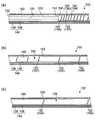
- FIG. 5is a diagram for explaining the arrangement of reinforcing pipes in the catheter constituting the flexible endoscope shown in FIG. (A) to (c) of FIG. 5 correspond to (a) to (c) of FIG. 3, respectively, and the description regarding the cross section of the reinforcing pipe 150 is omitted.
- a plurality of slit portions 154are formed in the reinforcing pipe 150 along the long axis direction.
- the distance between the slit portions 154 provided in the reinforcing pipe 150(that is, the distance between one slit portion 154 provided in the reinforcing pipe 150 and another slit portion 154 adjacent thereto) is , P d near the distal end of the catheter 102 ((a) in FIG. 5), P m in the central portion ((b) in FIG. 5), and P p near the proximal end ((c) in FIG. 5).
- the distance between the two adjacent slits 154 in P d near the distal end of the catheter 102 ((a) in FIG. 5)is the distance in the central portion P m of the catheter 102 ((b) in FIG. 5). and the spacing in the near the proximal end P p of the catheter 102 (the to FIG. 5 (c)) is shorter than.
- the distance between the two adjacent slits 154 at the central portion P m of the catheter 102 ((b) in FIG. 5)is the distance at P p near the proximal end of the catheter 102 ((c) in FIG. 5). Shorter than.
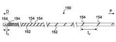
- FIG. 6is a diagram for explaining a reinforcing pipe arranged in the catheter constituting the flexible endoscope shown in FIG.
- the reinforcing pipe 150is, for example, an elongated pipe designed to have substantially the same outer diameter from the distal tip to the proximal tip, and is made of stainless steel, nitinol, aluminum, copper, or brass. It is composed of metal such as.
- the reinforcing pipe 150has, but is not necessarily limited to, an outer diameter of 0.05 mm to 2.7 mm, an inner diameter of 0.04 mm to 2.6 mm, and a length of 900 mm to 2400 mm.
- the outer diameter of the reinforcing pipe 150is substantially constant from the distal end to the proximal end.
- the reinforcing pipe 150 shown in FIG. 6is provided with a spiral slit 152 continuously provided along the outer circumference.
- the spiral slit 152is described as one continuous slit in FIG. 6, it is not limited to such a form.
- the spiral slitmay be provided as being composed of two or more slits along the outer circumference of the reinforcing pipe 150, and / or the slit may be intermittent in the middle. ..
- two adjacent slit portions 154are gradually expanded from the distal side (D) to the proximal side (P) by the spiral slit 152.
- the distance between two adjacent slits in the reinforcing panelmay be continuously expanded or discontinuously expanded.
- the distance between two adjacent slits 154 in the reinforcing pipe 150is not necessarily limited, and an arbitrary length can be selected by those skilled in the art.
- the distance ( Id ) between two adjacent slits 154 on the distal side (D)is, for example, 0.1 mm to 2 mm, preferably 0.3 mm to 1 mm, and the proximal side.
- the distance ( Ip ) between the two adjacent slit portions 154 in ( P )is, for example, 2 mm to 20 mm, preferably 4 mm to 10 mm.
- the reinforcing pipe 150is provided with a plurality of slit portions 154 as described above, so that the reinforcing pipe 150 has different flexibility at each of the distal end, the central portion, and the proximal end. Can have.
- a position at a predetermined distance from the distal tipfor example, a position preferably 50 cm to 150 cm, more preferably 80 cm to 100 cm from the distal tip) or distal.
- a length marker 155may be provided that describes information at a predetermined distance from the tip (for example, a distance of preferably 20 cm to 70 cm, preferably 30 cm to 60 cm from the distal tip).
- the length marker 155is composed of, for example, any one of numbers, symbols, figures, and the like, or a combination thereof.
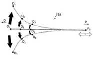
- FIG. 7is a diagram for schematically explaining the flexibility of the reinforcing pipe shown in FIG.
- the flexibility of the reinforcing pipe 150is most limited at position P 0 on the proximal side (P) (D 1 > D 2 > D 3 > P 0 ). In other words, the flexibility of the reinforcing pipe 150 increases toward the distal end (D 1 > D 2 > D 3 > P 0 ).
- the rigidity of the reinforcing pipe 150becomes the highest, and gradually decreases in the order of positions D 3 , D 2 , and D 1 (D 1 ⁇ D 2 ⁇ D 3). ⁇ P 0 ). That is, the proximal side of the reinforcing pipe 150 is less likely to buffer the force acting in the axial direction (white arrow), and the pushability, followability, and passability when the doctor advances the catheter are maintained. As a result, the reinforcing pipe 150 may have non-uniform (or sloped) flexibility from the distal end to the proximal end.
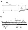
- FIGS. 8 and 9are diagrams for explaining an example of a reinforcing pipe that can be arranged in a catheter constituting the flexible endoscope of the present invention.
- a plurality of arcuate slits 152'provided intermittently along the outer circumferenceare provided.
- Reinforcing pipes 150'withinmay be used ((a) and (b) in FIGS. 9).
- the distance I'of two adjacent slits 154'provided near the distal end of the reinforcing pipe 150'is, for example, the distal end of the reinforcing pipe 150 shown in FIG. It is designed to be substantially the same as the distance ( Id ) between two adjacent slits provided in the vicinity.
- the proximal tip of the catheter 102is completely contained within the connecting plug 104 (see (a) and (b) of FIGS. 10).
- the proximal tip portion 158 of the reinforcing pipe 150also extends at least through the flexible accommodating portion 107 into the hollow cover (indicated by 105'in FIG. 10) of the connecting plug 104. .. This is because the proximal tip portion 158 of the reinforcing pipe 150 is arranged at such a position, so that the rigidity of the connecting portion between the catheter 102 and the connecting plug 104 can be increased.
- FIG. 11is a diagram for explaining an example of a flexible endoscope including another catheter of the present invention.
- the same reference numeralsare given to the configurations common to the above.
- the flexible endoscope 200includes a catheter 202 and a connection plug 104.
- the distal ends of the flexible tube 103, image guide 120 and light guide 140constitute the distal tip of the catheter 202, whereas the distal ends of the reinforcing pipe 250.
- the end 251is located proximal to each distal end of the flexible tube 103, image guide 120 and light guide 140. This makes it possible to reduce the rigidity of the distal tip of the catheter 202 due to the absence of the reinforcing pipe 250. As a result, the flexibility of the flexible pipe 103, the image guide 120, and the light guide 140 is increased, and the catheter 202 can be bent in a more free direction at P d2 near the distal end of the catheter 202.
- both the image guide 120 and the ride guide 140are arranged inside the reinforcing pipe 250. This allows both the image guide 120 and the ride guide 140 (except near their distal tips) to be protected by the reinforcing pipe 250.
- the reinforcing pipe 250 constituting the catheter 202 shown in FIG. 11Bhas the same structure as the reinforcing pipe 150 shown in FIGS. 3 and 6 above. Then, the plurality of slit portions 254 provided in the reinforcing pipe 250 are arranged so that the distance between the two adjacent slit portions 254 is longer on the proximal side than the distal side of the catheter 202 in the longitudinal direction of the reinforcing pipe 250. By being provided, it may have non-uniform (or sloped) flexibility from the distal end to the proximal end. As a result, the flexibility can be increased on the distal side of the catheter 202, the rigidity can be increased on the proximal side of the catheter 202, and the pushability when the doctor advances the catheter, It can maintain followability and passability.
- the flexible endoscope of the present inventionis provided with a catheter and a connecting plug as described above, and can be used as, for example, a vascular endoscope, a ureteroscope, or a salpingoscope.
- the flexible endoscope of the present inventionis preferably a vascular endoscope.
- FIG. 12is a diagram showing an example of an endoscope system in which the flexible endoscope of the present invention shown in FIG. 1 is connected to a repeater device and a medical console.
- the flexible endoscope 100 of the present inventionis connected to the repeater device 300 via a connection plug. Further, the repeater device 300 is connected to the medical console 400 via, for example, a cable 320. In this way, the endoscope system 500 is constructed.
- a doctormoves the catheter 102 of the flexible endoscope 100 to a desired position through, for example, a blood vessel of a patient, and a repeater device 300 is used to move the catheter 102 to a distal tip of the catheter 102.
- the image of the affected area obtained from the areacan be displayed on the display 440 of the medical console 400.
- the doctorperforms medical treatment such as enlarging / reducing the image displayed on the display, adjusting the brightness, recording or stopping the image, or playing back the recorded image through the operation buttons provided on the repeater device 300. It is possible to instruct the console.
- the present inventionis not limited to such an embodiment.
- the components of the repeater devicemay be incorporated directly into the console without going through the cable 320 to form one console device as a whole. That is, such a console device can also constitute an endoscope system together with the flexible endoscope of the present invention.
- the connection plug of the flexible endoscopeis connected to the console device via a reception port provided in the console device.
Landscapes
- Health & Medical Sciences (AREA)
- Life Sciences & Earth Sciences (AREA)
- Physics & Mathematics (AREA)
- Surgery (AREA)
- Optics & Photonics (AREA)
- Biomedical Technology (AREA)
- Animal Behavior & Ethology (AREA)
- Radiology & Medical Imaging (AREA)
- Nuclear Medicine, Radiotherapy & Molecular Imaging (AREA)
- Engineering & Computer Science (AREA)
- Biophysics (AREA)
- Heart & Thoracic Surgery (AREA)
- Medical Informatics (AREA)
- Molecular Biology (AREA)
- Pathology (AREA)
- General Health & Medical Sciences (AREA)
- Public Health (AREA)
- Veterinary Medicine (AREA)
- Astronomy & Astrophysics (AREA)
- General Physics & Mathematics (AREA)
- Endoscopes (AREA)
- Instruments For Viewing The Inside Of Hollow Bodies (AREA)
Abstract
Description
Translated fromJapanese本発明は、カテーテルおよびそれを備える軟性内視鏡に関し、より詳細には、管腔内への追随性および操作性が高められたカテーテルおよびそれを備える軟性内視鏡に関する。The present invention relates to a catheter and a flexible endoscope including the catheter, and more particularly to a catheter having improved operability and operability in a lumen and a flexible endoscope including the catheter.
近年、ヒトの身体内の診断、手術等を可能とする種々の内視鏡技術が開発されている。In recent years, various endoscopic technologies have been developed that enable diagnosis, surgery, etc. in the human body.
特に冠動脈等の血管内部における病変部の性状、長さ、および/または狭窄度を測定するために、血管内視鏡または血管内視鏡カテーテルと呼ばれる軟性内視鏡が使用される。こうした血管内視鏡は、例えば、消化管の診断、手術等に使用される消化管内視鏡と比較して、血管内の前進および後退を容易にするために長軸かつ軸径が極めて細く設計されている。In particular, a flexible endoscope called an angioscope or an endoscopic catheter is used to measure the properties, length, and / or degree of stenosis of a lesion inside a blood vessel such as a coronary artery. Such a vascular endoscope is designed to have a long axis and an extremely small shaft diameter in order to facilitate forward and backward movement in the blood vessel as compared with a gastrointestinal endoscope used for diagnosis, surgery, etc. of the gastrointestinal tract, for example. Has been done.
近年、ライトガイドとイメージガイドとを備える血管内視鏡が開発されている。当該血管内視鏡において、ライドガイドは、遠位端(すなわち、医師の手元から最も離れた側の内視鏡の先端部)から外部に対して光を照射することのできるガラスファイバから構成されている。イメージガイドは、当該遠位端にて得られた画像情報を医師側に伝送するための画像伝送用のイメージファイバから構成されている。In recent years, an angioscope equipped with a light guide and an image guide has been developed. In the vascular endoscope, the ride guide is composed of a glass fiber capable of irradiating the outside with light from the distal end (that is, the tip of the endoscope on the side farthest from the doctor's hand). ing. The image guide is composed of an image fiber for image transmission for transmitting the image information obtained at the distal end to the doctor side.
当該血管内視鏡では、これら2つのガイドが、近位端(すなわち、医師の手元に最も近い側の内視鏡の先端部)側で中継器装置と接続される。中継器装置はまた、伝送された画像情報を表示、解析、保管等するための種々の情報処理機能を備えた医療用コンソールに電気的に接続される。その結果、全体として1つの血管内視鏡システムが構成される。In the vascular endoscope, these two guides are connected to the repeater device at the proximal end (that is, the tip of the endoscope closest to the doctor's hand). The repeater device is also electrically connected to a medical console equipped with various information processing functions for displaying, analyzing, storing, and the like transmitted image information. As a result, one vascular endoscopy system is constructed as a whole.
こうした血管内視鏡のうち、特に血管内を前進かつ後退するカテーテル部分(以下、単純に「カテーテル」という)は、血管に対して低侵襲性であることが重要である。また血管内の損傷を防ぎ、かつ、体内の分岐しかつ細く入り組んだ血管内でカテーテルが自由に屈曲するためには、このカテーテルには充分な柔軟性を有していることが所望される。Among these angioscopes, it is important that the catheter part (hereinafter, simply referred to as "catheter") that advances and retracts in the blood vessel is minimally invasive to the blood vessel. Further, in order to prevent damage in the blood vessel and to allow the catheter to flex freely in the branched and narrowly intricate blood vessel in the body, it is desired that the catheter has sufficient flexibility.
しかし、このカテーテルの柔軟性は、遠位先端部を血管内の所望の部位まで前進させる医師にとってカテーテル操作性をより複雑なものにすることがある。However, the flexibility of this catheter can complicate catheter operability for physicians who advance the distal tip to the desired site within the blood vessel.
カテーテルは、例えば、患者の身体の所定部分を穿刺し、そこから医師がカテーテルを把持して血管内を押し進めることによって前進させられるが、仮にカテーテルが柔らか過ぎると、医師がそれを所定の力で血管内を押し進めようとしても、血管内でのカテーテルの押し込み性(pushability)、追随性(trackability)および通過性(crossability)に基づく力はカテーテルの柔軟性によって軸方向に緩衝され、結果として遠位端における微細な操作が困難となる場合があるからである。一方、これら押し込み性、追随性および通過性の向上のために、カテーテルが剛性を有していた場合、カテーテルの柔軟性が失われることにより、カテーテルが自由に屈曲することが困難となる場合がある。その結果、操作に所望以上の時間を要することにより、患者への身体的負担を増大させ、最悪の場合、遠位先端部が血管内を侵襲するリスクを高めることにもなる。The catheter is advanced, for example, by puncturing a predetermined part of the patient's body, from which the doctor grasps the catheter and pushes it into the blood vessel, but if the catheter is too soft, the doctor pushes it with a given force. When attempting to push through a vessel, the force based on the catheter's pushability, trackability, and crossability within the vessel is axially buffered by the flexibility of the catheter, resulting in distality. This is because fine operation at the edge may be difficult. On the other hand, in order to improve pushability, followability, and passability, when the catheter has rigidity, it may be difficult for the catheter to flex freely due to the loss of flexibility of the catheter. is there. As a result, the operation takes longer than desired, which increases the physical burden on the patient and, in the worst case, increases the risk of the distal tip invading the blood vessel.
このように血管内視鏡システムに用いられる比較的小径のカテーテルでは、柔軟性および剛性の両方を適切に制御する点で、さらなる技術改良が所望されている。As described above, in the relatively small-diameter catheter used in the angioscopy system, further technical improvement is desired in terms of appropriately controlling both flexibility and rigidity.
本発明は、上記問題の解決を課題とするものであり、その目的とするところは、近位端における押し込み性、追随性、および通過性を向上させるとともに、遠位端において適切な柔軟性を有する、カテーテルおよびそれを備える軟性内視鏡を提供することにある。An object of the present invention is to solve the above problems, and an object thereof is to improve pushability, followability, and passability at the proximal end, and to provide appropriate flexibility at the distal end. To provide a catheter and a flexible endoscope equipped with the catheter.
本発明は、可撓性チューブ、イメージガイド、ライトガイド、および補強パイプを備えるカテーテルであって、
該可撓性チューブが、該イメージガイド、該ライトガイドおよび該補強パイプを包囲しており、
該補強パイプが、長軸方向に沿って配置された複数のスリット部を有し、
該複数のスリット部が、該補強パイプの外周に沿って連続的または断続的に設けられた、少なくとも1つの螺旋状スリットまたは複数の円弧状スリットから構成されており、そして
該補強パイプの該長軸方向において、隣り合う2つの該スリット部の間隔が該カテーテルの遠位側よりも近位側で長い、カテーテルである。The present invention is a catheter comprising a flexible tube, an image guide, a light guide, and a reinforcing pipe.
The flexible tube surrounds the image guide, the light guide and the reinforcing pipe.
The reinforcing pipe has a plurality of slits arranged along the long axis direction.
The plurality of slits is composed of at least one spiral slit or a plurality of arcuate slits provided continuously or intermittently along the outer circumference of the reinforcing pipe, and the length of the reinforcing pipe. A catheter in which the distance between two adjacent slits in the axial direction is longer on the proximal side than on the distal side of the catheter.
1つの実施形態では、上記イメージガイドは上記補強パイプの内部に配置されている。In one embodiment, the image guide is arranged inside the reinforcing pipe.
1つの実施形態では、上記ライトガイドは複数のガラスファイバで構成されており、かつ該ライトガイドは上記補強パイプの外部に配置されている。In one embodiment, the light guide is composed of a plurality of glass fibers, and the light guide is arranged outside the reinforcing pipe.
1つの実施形態では、上記イメージガイドと上記ライトガイドとの間に上記補強パイプが配置されており、それにより、該イメージガイドと該ライトガイドとが空間的に分離されている。In one embodiment, the reinforcing pipe is arranged between the image guide and the light guide, whereby the image guide and the light guide are spatially separated.
1つの実施形態では、上記補強パイプの遠位端は、上記可撓性チューブ、上記イメージガイドおよび上記ライトガイドの各遠位端よりも近位に配置されている。In one embodiment, the distal end of the reinforcing pipe is located proximal to each of the distal ends of the flexible tube, the image guide and the light guide.
1つの実施形態では、上記補強パイプの遠位端は、上記可撓性チューブ、上記イメージガイド、および上記ライトガイドのいずれとも固定されていない。In one embodiment, the distal end of the reinforcing pipe is not fixed to any of the flexible tube, the image guide, and the light guide.
1つの実施形態では、上記隣り合う2つのスリット部の間隔は上記カテーテルの上記遠位側から上記近位側にかけて連続的または不連続に拡大している。In one embodiment, the distance between the two adjacent slits extends continuously or discontinuously from the distal side to the proximal side of the catheter.
1つの実施形態では、上記スリット部は、上記補強パイプの上記外周に沿って連続的に設けられた少なくとも1つの螺旋状スリットから構成されている。In one embodiment, the slit portion is composed of at least one spiral slit continuously provided along the outer circumference of the reinforcing pipe.
1つの実施形態では、上記スリット部は、上記補強パイプの上記外周に沿って断続的に設けられた複数の円弧状スリットから構成されている。In one embodiment, the slit portion is composed of a plurality of arc-shaped slits intermittently provided along the outer circumference of the reinforcing pipe.
1つの実施形態では、上記補強パイプの遠位先端部は環状の断端から構成されている。In one embodiment, the distal tip of the reinforcing pipe is composed of an annular stump.
1つの実施形態では、上記可撓性チューブは光透過性材料から構成されている。In one embodiment, the flexible tube is made of a light transmissive material.
さらなる実施形態では、上記補強パイプの外周上に、少なくとも1つのレングスマーカーが設けられている。In a further embodiment, at least one length marker is provided on the outer circumference of the reinforcing pipe.
本発明はまた、上記カテーテルと、
該カテーテルの近位端が収容され、かつ上記イメージガイドの近位端と光学的に接続された第1の接続端子、および上記ライトガイドと光学的に接続された第2の接続端子が突出する、接続プラグと
を備える、軟性内視鏡である。The present invention also includes the above catheter.
A first connecting terminal in which the proximal end of the catheter is housed and optically connected to the proximal end of the image guide and a second connecting terminal optically connected to the light guide project. It is a flexible endoscope equipped with a connection plug.
1つの実施形態では、本発明の軟性内視鏡は血管内視鏡である。In one embodiment, the flexible endoscope of the present invention is a vascular endoscope.
1つの実施形態では、上記接続プラグは、内部が中空となるように成形された2つの中空カバーで構成されており、かつ上記カテーテル内の上記補強パイプの近位端は、該中空カバー内にまで延びている。In one embodiment, the connecting plug is composed of two hollow covers molded so that the inside is hollow, and the proximal end of the reinforcing pipe in the catheter is in the hollow cover. Extends to.
本発明はまた、内視鏡システムであって、
上記軟性内視鏡;
該軟性内視鏡の上記第1の接続端子および上記第2の接続端子と光学的に接続された中継器装置;ならびに
画像情報を伝送するためのケーブルを介して該中継器装置と接続されたコンソール;
を備える、システムである。The present invention is also an endoscopic system.
The above flexible endoscope;
A repeater device optically connected to the first connection terminal and the second connection terminal of the flexible endoscope; and connected to the repeater device via a cable for transmitting image information. console;
It is a system equipped with.
本発明によれば、軟性内視鏡の操作性が向上し、内視鏡検査の際の検査の精度を高めかつその時間を短縮することにより、患者の身体的負担を低減することができる。本発明のカテーテルは、遠位端よりも近位端で剛性が高く、当該剛性は近位端から遠位端に向かって徐々に低下し、かつ近位端よりも遠位端で柔軟性を有し、当該柔軟性は遠位端から近位端に向かって徐々に低下するように、設計されている。このようなカテーテルを備える軟性内視鏡は、例えば、血管内を前進させる際、近位端では適切な押し込み性、追随性、および通過性を有するとともに遠位端では適切な柔軟性が保持され、遠位端先端部でのカテーテルの自由な屈曲を可能にする。According to the present invention, the operability of the flexible endoscope is improved, the accuracy of the examination at the time of endoscopy is improved, and the time is shortened, so that the physical burden on the patient can be reduced. The catheter of the present invention has higher rigidity at the proximal end than the distal end, and the rigidity gradually decreases from the proximal end toward the distal end, and becomes more flexible at the distal end than the proximal end. It has and is designed so that its flexibility gradually decreases from the distal end to the proximal end. A flexible endoscope equipped with such a catheter, for example, has appropriate indentability, followability, and passage at the proximal end and retains appropriate flexibility at the distal end when advancing in a blood vessel. Allows free flexion of the catheter at the distal end.
以下、本発明について詳述する。Hereinafter, the present invention will be described in detail.
(1.カテーテルおよび軟性内視鏡)
図1は、本発明のカテーテルを備える軟性内視鏡の一例を説明するための図である。(1. Catheter and flexible endoscope)
FIG. 1 is a diagram for explaining an example of a flexible endoscope including the catheter of the present invention.
図1に示すように、軟性内視鏡100は、カテーテル102と接続プラグ104とを備える。As shown in FIG. 1, the
カテーテル102は、好ましくは、1000mm~2500mm、より好ましくは1200mm~2300mmの長さを有し、そして後述するように、遠位先端部にて得られた画像情報を医師側に伝送するための1つまたはそれ以上のイメージファイバで構成されるイメージガイドと、複数のガラスファイバから構成されるライトガイドと、補強パイプと、当該イメージガイド、ライトガイドおよび補強パイプを長軸方向に沿って包囲する、可撓性チューブ103とを備える。可撓性チューブ103は、チューブ内部の視認性を高めるために光透過性材料(例えば、透明または半透明の材料)で構成されていることが好ましい。可撓性チューブ103を構成する材料としては、例えば、ポリイミド、フッ素系樹脂、PTFE(ポリテトラフルオロエチレン)、ナイロン、ポリウレタン、ポリプロピレン、塩化ビニル、シリコーンが挙げられる。可撓性チューブは、必ずしも限定されないが、例えば、0.3mm~3mm、好ましくは0.5mm~2mmの平均外径、および例えば、0.1mm~2.8mm、好ましくは0.2mm~0.7mmの平均内径を有する。The
カテーテル102はまた、好ましくは略円柱状の形状を有し、そして可撓性チューブ103の遠位端上に先端保護具160を備える。先端保護具160は、例えば、ステンレス、アルミニウム合金、プラチナ系合金、チタン、金などの金属、またはセラミックスなどの材料から構成されている。The
ここで、本明細書にて用いられる用語「遠位」とは、内視鏡のような器具および装置の位置を表す用語であって、当該器具または装置を医師が使用する際に、当該器具または装置のうち、医師に遠い側の部分を指し、そして用語「近位」とは、器具および装置の位置を表す用語であって、当該器具または装置を医師が使用する際に、当該器具または装置のうち、医師に近い側の部分を指して言う。Here, the term "distal" as used in the present specification is a term indicating the position of an instrument and a device such as an endoscope, and when the instrument or device is used by a doctor, the instrument is used. Or the part of the device that is far from the doctor, and the term "proximal" is a term that refers to the position of the device and device, and when the device or device is used by the doctor, the device or device. Refers to the part of the device that is closer to the doctor.
図2は、図1に示す軟性内視鏡を構成するカテーテル102の遠位先端部を短軸方向から見た模式図である。FIG. 2 is a schematic view of the distal tip of the
図2に示すようにカテーテル102の遠位先端部は、例えば、イメージガイド120が可撓性チューブ103内の略中心付近に配置され、複数のガラスファイバ138で構成されるライドガイド140が、イメージガイド120の外周の一部または全体に分散して配置されている。カテーテル102の遠位先端部は、可撓性チューブ103内でイメージガイド120およびライトガイド140が例えば、エポキシ接着剤のような公知の接着材料132によって固定されている。なお、図2に示す実施形態では、イメージガイド120およびライドガイド140の各遠位先端部はそのまま露出されているが、本発明はこれに限定されない。例えば、カテーテル102の遠位先端部には、イメージガイド120およびライドガイド140の遠位先端部と光学的に接続されたレンズが設けられていてもよい。As shown in FIG. 2, the distal tip of the
イメージガイド120は、例えば、長軸かつ略円柱状の1本のイメージファイバから構成されている。当該イメージファイバの具体例としては、画像伝送用ファイバとして公知のもの(例えば、好ましくは8000本~20000本のグラスファイバを規則的に配列して束ねたもの、または束ねかつ接着したもの、またはそれらを延伸したものが挙げられる。イメージガイド120の平均外径は、好ましくは0.05mm~1mmであり、より好ましくは0.1mm~0.5mmである。The
ライトガイド140を構成するガラスファイバ138は、例えば、長軸かつ略円柱状の形態を有し、例えば、各種技術分野において照明用ファイバとして公知のものが挙げられる。各ガラスファイバ138の平均外径は、好ましくは0.001mm~1mmであり、より好ましくは0.01mm~0.1mmである。このようなガラスファイバ138は、例えば、ライトガイド140の中間部分(すなわち、ライトガイド140のうち、遠位端近傍および近位端近傍の各部分を除いた部分)では、互いに接着されていない状態に保持されている。カテーテル102内において、ライトガイド140はまた、当該ガラスファイバ138を好ましくは1本~100本、より好ましくは10本~50本含む。The
再び図1を参照すると、カテーテル102を構成する可撓性チューブ103内のライトガイドは、接続プラグ104内の第1の接続端子106と光学的に接続されている。そして、カテーテル102を構成する可撓性チューブ103内のイメージガイドは、接続プラグ104内の第2の接続端子108と光学的に接続されている。Referencing FIG. 1 again, the light guide in the
さらに、図1に示される接続プラグ104では、可撓性チューブ103の近位端が、イメージガイドおよびライトガイドの近位端とともに、内部が中空となるように成形された2つのカバー105,105’に収容されている。そして、第1の接続端子106および第2の接続端子108は、接続プラグ104の中空カバー105,105’から突出して略平行になるように配置されている。ここで、可撓性チューブ103は、中空カバー105,105’に取り付けられた可撓性受容部107内を貫通して、当該中空カバー105,105’内で収容かつ固定されている。可撓性受容部107は、適度な弾性を備えている材料から構成されていることが好ましく、具体的な材料の例としては、シリコーンゴム、天然または合成ゴム、ポリイミド、ナイロン、ポリエチレンテレフタレート、ポリアミドなどが挙げられる。Further, in the
図3は、図1に示す軟性内視鏡を構成するカテーテルの長軸方向における模式断面図である。図3の(a)~(c)に示すように、カテーテル102において、可撓性チューブ103は、イメージガイド120と複数のガラスファイバ138から構成されるライトガイド140と補強パイプ150とを長軸方向に沿って包囲する。FIG. 3 is a schematic cross-sectional view of the catheter constituting the flexible endoscope shown in FIG. 1 in the long axis direction. As shown in FIGS. 3A to 3C, in the
ここで、図3の(a)に示すように、カテーテル102の遠位端近傍Pdにおいて、可撓性チューブ103、イメージガイド120およびライトガイド140の遠位端は、カテーテル102の遠位先端部を構成するのに対し、補強パイプ150の遠位端151は、可撓性チューブ103、イメージガイド120およびライトガイド140の各遠位端よりも近位側に配置されている。これにより、カテーテル102の遠位先端部では、補強パイプ150が含まれていないことによる剛性の低下が可能となる。また、補強パイプ150の遠位端151は、可撓性チューブ103、イメージガイド120、およびライトガイド140のいずれとも固定されていない。その結果、カテーテル102の遠位先端部では、可撓性パイプ103、イメージガイド120およびライトガイド140による可撓性を高め、カテーテル102の遠位端近傍Pdではカテーテル102をより自由な方向に屈曲させることができる。Here, as shown in FIG. 3A, in Pd near the distal end of the
なお、本発明の1つの実施形態では、カテーテル102は、図4に示すように補強パイプ150の内部にイメージガイド120が配置されている。これに対し、ガラスファイバ138で構成されるライドガイド140は、補強パイプ150の外部に配置されている。補強パイプ150に対し、イメージガイド120およびライトガイド140がそれぞれこのように配置されていることにより、カテーテル102は以下のような利点を有する。In one embodiment of the present invention, in the
すなわち、図4に示すような配置によれば、イメージガイド120は補強パイプ150に包囲されることにより、外部から過度の力が加えられた場合に容易に破損することを防止することができる。上述したように、カテーテル102において、イメージガイド120はカテーテル102の遠位先端部にて得られた画像情報を医師側に伝送するために機能する。そして、血管等の比較的狭い管腔内を通過するために、イメージガイド120はより小径かつ少ない本数(例えば、1本)で構成されることがある。補強パイプ150は、このようなイメージガイド120を外部から保護する役割を果たす。That is, according to the arrangement as shown in FIG. 4, the
一方、ライトガイド140は、カテーテル102の遠位先端部から管腔内に所定の光を照射して、イメージガイド120を通じて伝送される画像の視野を明るく保つために機能する。ライトガイド140を構成するガラスファイバ138は微細な直径を有し、これを複数使用することで、所望の光量を供給することができる。ここで、可撓性チューブ103が透明または半透明の光透過性材料で構成されている場合、ライトガイド140(ガラスファイバ138)が補強ファイバ150の外部に配置されていると、仮にカテーテル102のいずれかの部分で、ガラスファイバ138の一部が破損してもその破損部分において光が漏出する。このため、カテーテル102の品質不良等の発見が可能となる。On the other hand, the
さらに、図4において、イメージガイド120と補強パイプ150との間、補強パイプ150とライトガイド140(またはガラスファイバ138)との間は、接着等がなされておらず、可撓性チューブ103内において、イメージガイド120、補強パイプ150、ならびにライトガイド140(およびガラスファイバ138)は互いに任意に摺動可能であることが好ましい。Further, in FIG. 4, there is no adhesion between the
イメージガイド120と補強パイプ150との間、補強パイプ150とライトガイド140(またはガラスファイバ138)との間は、接着等がなされておらず、ライトガイド140(ガラスファイバ138)とイメージガイド120が補強ファイバ150により一部または全長において空間的に分離されていることで、カテーテルを曲げた際、イメージガイド120を補強し、かつイメージガイド120とライトガイド140の摩擦による損傷を防ぐとともに、比較的撓みの大きなライトガイド140の可動性をより担保することができる。There is no adhesion between the
図5は、図1に示す軟性内視鏡を構成するカテーテル内の補強パイプの配置を説明するための図である。図5の(a)~(c)は、図3の(a)~(c)にそれぞれ対応し、補強パイプ150の断面に関する記載を省略している。FIG. 5 is a diagram for explaining the arrangement of reinforcing pipes in the catheter constituting the flexible endoscope shown in FIG. (A) to (c) of FIG. 5 correspond to (a) to (c) of FIG. 3, respectively, and the description regarding the cross section of the reinforcing
図5の(a)~(c)に示すように、補強パイプ150には、長軸方向に沿って複数のスリット部154が形成されている。As shown in FIGS. 5A to 5C, a plurality of
本発明において、この補強パイプ150に設けられたスリット部154の間隔(すなわち、補強パイプ150に設けられた1つのスリット部154と、これに隣り合う他のスリット部154との間の距離)は、カテーテル102の遠位端近傍Pd(図5の(a))、中央部分Pm(図5の(b))、および近位端近傍Pp(図5の(c))において異なる長さを有する。すなわち、図5の(a)~(c)に示すように、本発明においては、補強パイプ150の長軸方向において、隣り合う2つのスリット部154の間隔が、カテーテル102の遠位側よりも近位側で長くなるように設計されている。これにより、カテーテル102の遠位端近傍Pdにおける隣り合う2つのスリット部154の間隔(図5の(a))は、カテーテル102の中央部分Pmにおける当該間隔(図5の(b))およびカテーテル102の近位端近傍Ppにおける当該間隔(図5の(c))よりも短い。また、かつカテーテル102の中央部分Pmにおける隣り合う2つのスリット部154の間隔(図5の(b))は、カテーテル102の近位端近傍Ppにおける当該間隔(図5の(c))よりも短い。In the present invention, the distance between the
図6は、図1に示す軟性内視鏡を構成するカテーテル内に配置された補強パイプを説明するための図である。FIG. 6 is a diagram for explaining a reinforcing pipe arranged in the catheter constituting the flexible endoscope shown in FIG.
本発明において、補強パイプ150は、例えば遠位先端部から近位先端部にかけて外径が略同一の外径を有するように設計された細長い管であり、ステンレススチール、ニチノール、アルミニウム、銅、真鍮などの金属で構成されている。補強パイプ150は必ずしも限定されないが、例えば、0.05mm~2.7mmの外径を有し、0.04mm~2.6mmの内径を有し、そして900mm~2400mmの長さを有する。1つの実施形態では、補強パイプ150の外径は、遠位端から近位端にかけてほぼ一定である。In the present invention, the reinforcing
また、図6に示す補強パイプ150には、外周に沿って連続的に設けられた螺旋状スリット152が設けられている。なお、図6では、螺旋状スリット152が、1本の連続したスリットとして記載されているが、このような形態に限定されない。例えば、当該螺旋状スリットは、補強パイプ150の外周に沿って2本以上のスリットから構成されるものとして設けられていてもよく、および/または当該スリットは途中で断続したものであってもよい。Further, the reinforcing
さらに、図6に示す補強パイプ150では、この螺旋状スリット152によって、隣り合う2つのスリット部154が、遠位側(D)から近位側(P)にかけて徐々に拡大している。本発明において、この補強パネルにおける隣り合う2つのスリット部の間隔は、連続に拡大するものであっても不連続に拡大するものであってもよい。補強パイプ150における隣り合う2つのスリット部154の間隔は、必ずしも限定されず、当業者によって任意の長さを選択することができる。1つの実施形態では、遠位側(D)における隣り合う2つのスリット部154の間隔(Id)は、例えば、0.1mm~2mm、好ましくは0.3mm~1mmであり、そして近位側(P)における隣り合う2つのスリット部154の間隔(Ip)は、例えば、2mm~20mm、好ましくは4mm~10mmである。Further, in the reinforcing
本発明において、補強パイプ150に対し、上記のような複数のスリット部154が設けられていることにより、補強パイプ150は、遠位端、中央部分、および近位端のそれぞれにおいて異なる屈曲性を有し得る。In the present invention, the reinforcing
なお、補強パイプ150の外周面上には、遠位先端部から所定の距離となる位置(例えば遠位先端部から好ましくは50cm~150cm、より好ましくは80cm~100cmとなる位置)、または遠位先端部から所定の間隔(例えば遠位先端部から好ましくは20cm~70cm、好ましくは30cm~60cmの間隔)の情報を記載したレングスマーカー155が設けられていてもよい。レングスマーカー155は、例えば、数字、記号、図形等のいずれか1つまたはそれらの組み合わせで構成されている。術者(例えば医師)が本発明の軟性内視鏡を患者に対して使用する際、当該術者は、レングスマーカー155に記載された情報を、例えば図1に示す例えば透明または半透明の可撓性チューブ103を介して視認することができる。これにより、患者の体内に挿入した軟性内視鏡の長さを目視で把握することができる。On the outer peripheral surface of the reinforcing
図7は、図6に示す補強パイプの屈曲性を模式的に説明するための図である。FIG. 7 is a diagram for schematically explaining the flexibility of the reinforcing pipe shown in FIG.
補強パイプ150に設けられた隣り合う2つのスリット部の間隔が、遠位側(D)の位置D1、D2、D3から近位側(P)の位置P0にかけて、徐々に拡大するように設けられている場合、遠位側(D)の位置D1、D2、D3における屈曲性(黒矢印)は、位置D1が最も大きく、位置D2およびD3の順に徐々に低下し、そして近位側(P)の位置P0では補強パイプ150の屈曲性は最も制限される(D1>D2>D3>P0)。言い換えれば、補強パイプ150の可撓性は遠位端に向かうほど大きくなる(D1>D2>D3>P0)。これに対し、近位側(P)の位置P0では補強パイプ150の剛性は最も高くなり、位置D3、D2、およびD1の順に徐々に低下する(D1<D2<D3<P0)。すなわち、補強パイプ150の近位側ほど、軸方向に働く力(白矢印)が緩衝されにくくなり、医師がカテーテルを前進させる際の押し込み性、追随性および通過性は保持される。その結果、補強パイプ150は、遠位端から近位端にかけて不均一な(あるいは勾配のある)屈曲性を有し得る。The distance between the two slit portions adjacent which is provided on the reinforcing
図8および9は、本発明の軟性内視鏡を構成するカテーテル内に配置可能な補強パイプの例を説明するための図である。8 and 9 are diagrams for explaining an example of a reinforcing pipe that can be arranged in a catheter constituting the flexible endoscope of the present invention.
本発明においては、図8の(a)および(b)に示すような螺旋状スリット152を有する補強パイプ150の代わりに、外周に沿って断続的に設けられた複数の円弧状スリット152’を有する補強パイプ150’が用いられてもよい(図9の(a)および(b))。例えば、図9の(b)において、補強パイプ150’の遠位端近傍に設けられた隣り合う2つのスリット部154’の間隔I’は、例えば、図6に示す補強パイプ150の遠位端近傍に設けられた隣り合う2つのスリット部の間隔(Id)と略同様となるように設計されている。In the present invention, instead of the reinforcing
なお、図8の(a)および(b)に示す補強パイプ150、ならびに図9の(a)および(b)に示す補強パイプ150’はいずれも、遠位先端部が環状の断端156,156’を有していること(すなわち、各補強パイプの遠位側における端部がスリットによって分断されていないこと)が好ましい。補強パイプ150,150’の遠位先端部が環状であることにより、例えば、カテーテルが管腔内を前進または後退する際に、補強パイプの断端がほつれることを防止する、カテーテルの組立ての際に補強パイプ内に光ファイバを挿入し易くする、および/または組立ておよび使用の際にその端部による光ファイバの破損を防止することができる。The reinforcing
本発明の軟性内視鏡において、カテーテル102の近位先端部は、接続プラグ104内に完全に収容されていることが望ましい(図10の(a)および(b)を参照のこと)。その際、補強パイプ150の近位先端部158もまた、少なくとも可撓性収容部107を通って接続プラグ104の中空カバー(図10では、105’で示す)内にまで延びていることが好ましい。補強パイプ150の近位先端部158がこのような位置に配置されていることにより、カテーテル102と接続プラグ104との間の接続部分の剛性を高めることができるからである。In the flexible endoscope of the present invention, it is desirable that the proximal tip of the
図11は、本発明の他のカテーテルを備える軟性内視鏡の例を説明するための図である。なお、図11において、上記と共通する構成には同一の符号が付されている。FIG. 11 is a diagram for explaining an example of a flexible endoscope including another catheter of the present invention. In FIG. 11, the same reference numerals are given to the configurations common to the above.
図11の(a)に示すように、軟性内視鏡200は、カテーテル202と接続プラグ104とを備える。As shown in FIG. 11A, the
カテーテル202の遠位端近傍Pd2において、可撓性チューブ103、イメージガイド120およびライトガイド140の遠位端は、カテーテル202の遠位先端部を構成するのに対し、補強パイプ250の遠位端251は、可撓性チューブ103、イメージガイド120およびライトガイド140の各遠位端よりも近位側に配置されている。これにより、カテーテル202の遠位先端部では、補強パイプ250が含まれていないことによる剛性の低下が可能となる。その結果、可撓性パイプ103、イメージガイド120およびライトガイド140による可撓性を高め、カテーテル202の遠位端近傍Pd2ではカテーテル202をより自由な方向に屈曲させることができる。At Pd2 near the distal end of the
さらに図11の(b)に示すように、カテーテル202は、補強パイプ250の内部にイメージガイド120およびライドガイド140(ガラスファイバ138)の両方が配置されている。これにより、イメージガイド120およびライドガイド140の両方を(それらの遠位先端部近傍を除いて)、補強パイプ250によって保護することができる。Further, as shown in FIG. 11 (b), in the
図11の(b)に示すカテーテル202を構成する補強パイプ250は、上記図3、図6等に示した補強パイプ150と同様の構造を有する。そして、補強パイプ250に設けられた複数のスリット部254が補強パイプ250の長軸方向において、隣り合う2つのスリット部254の間隔がカテーテル202の遠位側よりも近位側で長くなるように設けられていることにより、遠位端から近位端にかけて不均一な(あるいは勾配のある)屈曲性を有し得る。その結果、カテーテル202の近位側よりも遠位側において屈曲性を高めることができ、カテーテル202の遠位側よりも近位側において剛性を高め、医師がカテーテルを前進させる際の押し込み性、追随性および通過性を保持することができる。The reinforcing
本発明の軟性内視鏡は、上記のようなカテーテルおよび接続プラグを備え、例えば、血管内視鏡、尿管鏡、または卵管鏡として使用され得る。本発明の軟性内視鏡は、血管内視鏡であることが好ましい。The flexible endoscope of the present invention is provided with a catheter and a connecting plug as described above, and can be used as, for example, a vascular endoscope, a ureteroscope, or a salpingoscope. The flexible endoscope of the present invention is preferably a vascular endoscope.
(2.内視鏡システム)
図12は、図1に示す本発明の軟性内視鏡を、中継器装置および医療用コンソールに接続した内視鏡システムの一例を示す図である。(2. Endoscope system)
FIG. 12 is a diagram showing an example of an endoscope system in which the flexible endoscope of the present invention shown in FIG. 1 is connected to a repeater device and a medical console.
図12に示すように、本発明の軟性内視鏡100は、接続プラグを介して中継器装置300に接続される。さらに中継器装置300は例えばケーブル320を介して医療用コンソール400に接続される。このようにして、内視鏡システム500が構築される。As shown in FIG. 12, the
本発明において、内視鏡システム500は、医師が軟性内視鏡100のカテーテル102を、例えば患者の血管内を通じて所望の位置にまで移動させ、中継器装置300を用いてカテーテル102の遠位先端部から得られた患部の画像を医療用コンソール400のディスプレイ440に表示することができる。この際、医師は、中継器装置300に設けられた操作ボタンを通じて、ディスプレイに表示された画像の拡大および縮小、明るさの調整、ならびに画像の録画またはその停止、あるいは録画画像の再生などを医療用コンソールに指示することが可能となる。In the present invention, in the
なお、上記では、中継器装置300と医療用コンソール400とがケーブル320を介して接続される例について説明したが、本発明はこのような実施形態にのみ限定されるものではない。例えば、中継器装置の構成部品が、上記ケーブル320を介することなく、コンソール内に直接組み込まれ、全体として1つのコンソール装置を形成されているものであってもよい。すなわち、このようなコンソール装置もまた、本発明の軟性内視鏡とともに内視鏡システムを構成し得る。この場合、軟性内視鏡の接続プラグは、コンソール装置内に設けられた受入口を介して当該コンソール装置と接続される。Although the example in which the
100,200 軟性内視鏡
102,202 カテーテル
103 可撓性チューブ
104 接続プラグ
105,105’ 中空カバー
107 可撓性受容部
120 イメージガイド
138 ガラスファイバ
140 ライトガイド
150,150’,250 補強パイプ
152,252 螺旋状スリット
152’ 円弧状スリット
154,154’,254 スリット部
155 レングスマーカー
160 先端保護具
300 中継器装置
400 医療用コンソール
500 内視鏡システム100,200 Flexible endoscope 102,202
Claims (16)
Translated fromJapanese該可撓性チューブが、該イメージガイド、該ライトガイドおよび該補強パイプを包囲しており、
該補強パイプが、長軸方向に沿って配置された複数のスリット部を有し、
該複数のスリット部が、該補強パイプの外周に沿って連続的または断続的に設けられた、少なくとも1つの螺旋状スリットまたは複数の円弧状スリットから構成されており、そして
該補強パイプの該長軸方向において、隣り合う2つの該スリット部の間隔が該カテーテルの遠位側よりも近位側で長い、カテーテル。A catheter with a flexible tube, image guide, light guide, and reinforcing pipe.
The flexible tube surrounds the image guide, the light guide and the reinforcing pipe.
The reinforcing pipe has a plurality of slits arranged along the long axis direction.
The plurality of slits is composed of at least one spiral slit or a plurality of arcuate slits provided continuously or intermittently along the outer circumference of the reinforcing pipe, and the length of the reinforcing pipe. A catheter in which the distance between two adjacent slits in the axial direction is longer on the proximal side than on the distal side of the catheter.
該カテーテルの近位端が収容され、かつ前記イメージガイドの近位端と光学的に接続された第1の接続端子、および前記ライトガイドと光学的に接続された第2の接続端子が突出する、接続プラグと
を備える、軟性内視鏡。The catheter according to any one of claims 1 to 12,
A first connecting terminal that accommodates the proximal end of the catheter and is optically connected to the proximal end of the image guide and a second connecting terminal that is optically connected to the light guide project. A flexible endoscope, equipped with a connection plug.
請求項13から15のいずれかに記載の軟性内視鏡;
該軟性内視鏡の前記第1の接続端子および前記第2の接続端子と光学的に接続された中継器装置;ならびに
画像情報を伝送するためのケーブルを介して該中継器装置と接続されたコンソール;
を備える、システム。It ’s an endoscopic system,
The flexible endoscope according to any one of claims 13 to 15;
A repeater device optically connected to the first connection terminal and the second connection terminal of the flexible endoscope; and connected to the repeater device via a cable for transmitting image information. console;
The system.
Applications Claiming Priority (2)
| Application Number | Priority Date | Filing Date | Title |
|---|---|---|---|
| JP2019084731AJP2020178937A (en) | 2019-04-25 | 2019-04-25 | Catheter and flexible endoscope with it |
| JP2019-084731 | 2019-04-25 |
Publications (1)
| Publication Number | Publication Date |
|---|---|
| WO2020218404A1true WO2020218404A1 (en) | 2020-10-29 |
Family
ID=72941988
Family Applications (1)
| Application Number | Title | Priority Date | Filing Date |
|---|---|---|---|
| PCT/JP2020/017458CeasedWO2020218404A1 (en) | 2019-04-25 | 2020-04-23 | Catheter and flexible endoscope comprising same |
Country Status (2)
| Country | Link |
|---|---|
| JP (1) | JP2020178937A (en) |
| WO (1) | WO2020218404A1 (en) |
Families Citing this family (1)
| Publication number | Priority date | Publication date | Assignee | Title |
|---|---|---|---|---|
| JP7502214B2 (en)* | 2021-02-12 | 2024-06-18 | テルモ株式会社 | Catheter System |
Citations (2)
| Publication number | Priority date | Publication date | Assignee | Title |
|---|---|---|---|---|
| JP2006055659A (en)* | 2005-10-21 | 2006-03-02 | Olympus Corp | Endoscope |
| WO2015098236A1 (en)* | 2013-12-24 | 2015-07-02 | オリンパス株式会社 | Endoscope |
- 2019
- 2019-04-25JPJP2019084731Apatent/JP2020178937A/enactivePending
- 2020
- 2020-04-23WOPCT/JP2020/017458patent/WO2020218404A1/ennot_activeCeased
Patent Citations (2)
| Publication number | Priority date | Publication date | Assignee | Title |
|---|---|---|---|---|
| JP2006055659A (en)* | 2005-10-21 | 2006-03-02 | Olympus Corp | Endoscope |
| WO2015098236A1 (en)* | 2013-12-24 | 2015-07-02 | オリンパス株式会社 | Endoscope |
Also Published As
| Publication number | Publication date |
|---|---|
| JP2020178937A (en) | 2020-11-05 |
Similar Documents
| Publication | Publication Date | Title |
|---|---|---|
| US10856727B2 (en) | Endoscopic methods and devices for transnasal procedures | |
| CA2453743C (en) | Transparent dilator device and method of use | |
| EP3560412B1 (en) | Fully integrated disposable tissue visualization device | |
| US8333691B2 (en) | Endoscope comprising a flexible probe | |
| US9107574B2 (en) | Endoscopic methods and devices for transnasal procedures | |
| EP1558124B1 (en) | Endoscopic imaging system including removable deflection device | |
| US5318526A (en) | Flexible endoscope with hypotube activating wire support | |
| JP4920235B2 (en) | Transparent dilator and method of use | |
| US8187172B2 (en) | Endoscope cap with aperture | |
| JP2018525197A (en) | Endoscope with variable outer shape tip | |
| US20170231481A1 (en) | Insertion device assembly for nasal sinuses | |
| JP3780066B2 (en) | Medical tube | |
| JP2002330924A (en) | Endoscope | |
| WO2020218404A1 (en) | Catheter and flexible endoscope comprising same | |
| JP2019503734A (en) | Fixed guide wire | |
| JPH07184837A (en) | Cover type endoscope | |
| JP4527111B2 (en) | Guide wire structure for insertion into the interior space | |
| US11304594B2 (en) | Articulating medical device | |
| US20230065294A1 (en) | Fully integrated, disposable tissue visualization device with off axis viewing | |
| JP6705966B2 (en) | Flexible endoscope and endoscope system including the same | |
| JPH01101958A (en) | Endoscope | |
| JPH02114930A (en) | Insertion assist jig for endoscope | |
| JP2014200336A (en) | Medical apparatus |
Legal Events
| Date | Code | Title | Description |
|---|---|---|---|
| 121 | Ep: the epo has been informed by wipo that ep was designated in this application | Ref document number:20795712 Country of ref document:EP Kind code of ref document:A1 | |
| NENP | Non-entry into the national phase | Ref country code:DE | |
| 122 | Ep: pct application non-entry in european phase | Ref document number:20795712 Country of ref document:EP Kind code of ref document:A1 |