WO2020210972A1 - Wearable image display device for surgery and surgical information real-time presentation system - Google Patents
Wearable image display device for surgery and surgical information real-time presentation systemDownload PDFInfo
- Publication number
- WO2020210972A1 WO2020210972A1PCT/CN2019/082834CN2019082834WWO2020210972A1WO 2020210972 A1WO2020210972 A1WO 2020210972A1CN 2019082834 WCN2019082834 WCN 2019082834WWO 2020210972 A1WO2020210972 A1WO 2020210972A1
- Authority
- WO
- WIPO (PCT)
- Prior art keywords
- medical
- surgical
- image
- information
- display
- Prior art date
- Legal status (The legal status is an assumption and is not a legal conclusion. Google has not performed a legal analysis and makes no representation as to the accuracy of the status listed.)
- Ceased
Links
Images


Classifications
- A—HUMAN NECESSITIES
- A61—MEDICAL OR VETERINARY SCIENCE; HYGIENE
- A61B—DIAGNOSIS; SURGERY; IDENTIFICATION
- A61B34/00—Computer-aided surgery; Manipulators or robots specially adapted for use in surgery
- A61B34/20—Surgical navigation systems; Devices for tracking or guiding surgical instruments, e.g. for frameless stereotaxis
- G—PHYSICS
- G06—COMPUTING OR CALCULATING; COUNTING
- G06F—ELECTRIC DIGITAL DATA PROCESSING
- G06F17/00—Digital computing or data processing equipment or methods, specially adapted for specific functions
Definitions
- the inventionrelates to a wearable image display device and a presentation system, in particular to a wearable image display device for surgery and a real-time presentation system of surgery information.
- the purpose of the present inventionis to provide a surgical wearable image display device and a real-time surgical information presentation system, which can assist or train users to operate medical instruments.
- a wearable image display device for surgeryincludes a display, a wireless receiver, and a processing core.
- the wireless receiverwirelessly receives medical images or medical device information in real time;
- the processing coreis coupled to the wireless receiver and the display to display the medical images or medical device information on the display.
- the medical imageis an artificial medical image of an artificial limb.
- the surgical wearable image display deviceis smart glasses or a head-mounted display.
- the medical appliance informationincludes location information and angle information.
- the wireless receiverwirelessly receives the surgical target information in real time, and the processing core displays the medical image, medical appliance information, or surgical target information on the display.
- the surgical target informationincludes position information and angle information.
- the wireless receiverwirelessly receives the surgical guidance video in real time, and the processing core displays the medical image, medical appliance information or the surgical guidance video on the display.
- a real-time presentation system for surgical informationincludes the aforementioned surgical wearable image display device and a server.
- the server and the wireless receiverare connected wirelessly to wirelessly transmit medical images and medical device information in real time.
- the servertransmits medical images and medical device information through two network ports, respectively.
- the systemfurther includes an optical positioning device.
- the optical positioning devicedetects the position of the medical appliance and generates a positioning signal.
- the servergenerates medical appliance information according to the positioning signal.
- the surgical wearable image display device and surgical information real-time presentation system of the present disclosurecan assist or train users to operate medical instruments.
- the training system of the present disclosurecan provide trainees with a realistic surgical training environment, thereby effectively Assist trainees to complete surgical training.
- the surgical performercan also perform a simulated operation on the prosthesis first, and use the surgical wearable image display device and the surgical information real-time display system to review or review the simulated surgery performed in advance before the actual operation, so that the surgical performer Can quickly grasp the key points of surgery or points that need attention.
- surgical wearable image display devices and surgical information real-time display systemscan also be applied to actual surgical procedures.
- Medical imagessuch as ultrasound images are transmitted to surgical wearable image display devices such as smart glasses. This display method It can make the operator no longer need to turn his head to look at the screen.
- FIG. 1Ais a block diagram of an embodiment of a real-time presentation system for surgical information.
- FIG. 1Bis a schematic diagram of the wearable image display device for surgery in FIG. 1A receiving medical images or medical device information.
- FIG. 1Cis a schematic diagram of the transmission between the server and the surgical wearable image display device in FIG. 1A.
- Figure 1Dis a schematic diagram of the server in Figure 1A transmitting through two network ports.
- Fig. 2Ais a block diagram of an optical tracking system according to an embodiment.
- FIGS. 2B and 2Care schematic diagrams of an optical tracking system according to an embodiment.
- Fig. 2Dis a schematic diagram of a three-dimensional model of a surgical situation in an embodiment.
- Fig. 3is a functional block diagram of a surgical training system according to an embodiment.
- Fig. 4is a block diagram of a training system for medical appliance operation according to an embodiment.
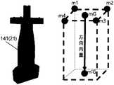
- Fig. 5Ais a schematic diagram of a three-dimensional model of a surgical scenario according to an embodiment.
- FIG. 5Bis a schematic diagram of a three-dimensional model of an entity medical image according to an embodiment.
- FIG. 5Cis a schematic diagram of a three-dimensional model of an artificial medical image according to an embodiment.
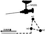
- 6A to 6Dare schematic diagrams of the direction vector of the medical appliance according to an embodiment.
- FIG. 7A to 7Dare schematic diagrams of the training process of the training system in an embodiment.
- Fig. 8Ais a schematic diagram of a finger structure according to an embodiment.
- Fig. 8Bis a schematic diagram of applying principal component analysis on bones from computed tomography images in an embodiment.
- FIG. 8Cis a schematic diagram of applying principal component analysis on the skin from a computed tomography image in an embodiment.
- Fig. 8Dis a schematic diagram of calculating the distance between the bone spindle and the medical appliance in an embodiment.
- Fig. 8Eis a schematic diagram of an artificial medical image according to an embodiment.
- FIG. 9Ais a block diagram for generating artificial medical images according to an embodiment.
- Fig. 9Bis a schematic diagram of an artificial medical image according to an embodiment.
- 10A and 10Bare schematic diagrams of the artificial hand model and the correction of ultrasonic volume according to an embodiment.
- Fig. 10Cis a schematic diagram of ultrasonic volume and collision detection in an embodiment.
- FIG. 10Dis a schematic diagram of an artificial ultrasound image according to an embodiment.
- FIG. 11A and 11Bare schematic diagrams of an operation training system according to an embodiment.
- 12A and 12Bare schematic diagrams of images of the training system according to an embodiment.
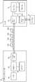
- FIG. 1Ais a block diagram of a real-time presentation system for surgical information according to an embodiment.
- the surgical information real-time presentation systemincludes a surgical wearable image display device 6 (hereinafter referred to as the display device 6) and a server 7.
- the display device 6includes a processing core 61, a wireless receiver 62, a display 63 and a storage element 64.
- the wireless receiver 62wirelessly receives medical images 721 or medical appliance information 722 in real time.
- the processing core 61is coupled to the storage element 64, and the processing core 61 is coupled to the wireless receiver 62 and the display 63 to display the medical image 721 or the medical appliance information 722 on the display 63.
- the server 7includes a processing core 71, an input/output interface 72, an input/output interface 74 and a storage element 73.
- the processing core 71is coupled to the I/O interface 72, the I/O interface 74, and the storage element 73.
- the server 7is wirelessly connected to the wireless receiver 62, and wirelessly transmits medical images 721 and medical appliance information 722 in real time.
- the surgical information real-time presentation systemcan also include a display device 8, and the server 7 can also output information to the display device 8 for display through the I/O interface 74.
- the processing cores 61 and 71are, for example, processors, controllers, etc.
- the processorsinclude or multiple cores.
- the processormay be a central processing unit or a graphics processor, and the processing cores 61 and 71 may also be the cores of a processor or a graphics processor.
- the processing cores 61 and 71may also be one processing module, and the processing module includes multiple processors.
- the storage components 64 and 73store program codes for execution by the processing cores 61 and 71.
- the storage components 64 and 73include non-volatile memory and volatile memory, such as hard disks, flash memory, solid state disks, and optical discs. and many more. Volatile memory is, for example, dynamic random access memory, static random access memory, and so on.
- the program codeis stored in a non-volatile memory, and the processing cores 61 and 71 can load the program code from the non-volatile memory to the volatile memory, and then execute the program code.
- the wireless receiver 62can wirelessly receive the surgical target information 723 in real time, and the processing core 61 can display the medical image 721, the medical appliance information 722, or the surgical target information 723 on the display 63.
- the wireless receiver 62can wirelessly receive the surgical guidance video 724 in real time, and the processing core 61 displays the medical image 721, medical appliance information 722 or the surgical guidance video 724 on the display 63.
- Medical images, medical device information, surgical target information or surgical guidance videocan guide or prompt the user to take the next action.
- the wireless receiver 62 and the I/O interface 72may be wireless transceivers, which conform to a wireless transmission protocol, such as a wireless network or Bluetooth.
- the instant transmission methodis, for example, wireless network transmission or Bluetooth transmission.
- This embodimentadopts wireless network transmission, and the wireless network is, for example, Wi-Fi specifications or compliance with IEEE 802.11b, IEEE 802.11g, IEEE 802.11n and other specifications.
- FIG. 1Bis a schematic diagram of the surgical wearable image display device in FIG. 1A receiving medical images or medical device information.
- Wearable image display devices for surgeryare smart glasses or head-mounted displays.
- Smart glassesare wearable computer glasses that can increase the information seen by the wearer.
- smart glassescan also be said to be wearable computer glasses, which can change the optical characteristics of the glasses during execution.
- Smart glassescan superimpose information into the field of view and hands-free applications.
- the overlapping of information to the field of viewcan be achieved by the following methods: optical head-mounted display (OHMD), embedded wireless glasses with transparent head-up display (HUD), Or augmented reality (AR) and so on.
- Hands-free applicationscan be achieved through a voice system, which uses natural language voice commands to communicate with smart glasses.
- the ultrasound imagesare transmitted to the smart glasses and displayed so that users no longer need to turn their heads to look at the screen.
- the medical image 721is an artificial medical image of an artificial limb.
- the artificial medical imageis a medical image generated for the artificial limb.
- the medical imageis, for example, an ultrasonic image.
- the medical appliance information 722includes position information and angle information, such as the tool information (Tool Information) shown in FIG. 1B.
- the position informationincludes the XYZ coordinate position, and the angle information includes the ⁇ angle.
- the surgical target information 723includes position information and angle information, such as the target information (Target Information) shown in FIG. 1B.
- the position informationincludes the XYZ coordinate position, and the angle information includes the ⁇ angle.
- the content of the surgical guidance video 724may be as shown in FIGS. 7A to 7D, which present the medical appliances and operations used in each stage of the operation.
- the display device 6may have a sound input element such as a microphone, and may be used for the aforementioned hands-free application.
- the usercan speak to give voice commands to the display device 6 to control the operation of the display device 6. For example, start or stop all or part of the operations described below. This is conducive to the operation, and the user can control the display device 6 without putting down the utensils held by the hand.
- the screen of the display device 6may display an icon to indicate that it is currently in the voice operation mode.
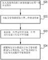
- FIG. 1Cis a schematic diagram of the transmission between the server and the surgical wearable image display device in FIG. 1A.
- the transmission between the server 7 and the display device 6includes steps S01 to S08.
- step S01the server 7 first transmits the image size information to the display device 6.
- step S02the display device 6 receives the image size information and sends it back for confirmation.
- step S03the server 7 divides the image into multiple parts and transmits them to the display device 6 sequentially.
- step S04the display device 6 receives the image size information and sends it back for confirmation. Steps S03 and S04 will continue to be repeated until the display device 6 has received the entire image.
- step S05after the entire image reaches the display device 6, the display device 6 starts processing the image. Since the bmp format is too large for real-time transmission, the server 7 can compress the image from the bmp format to the JPEG format to reduce the size of the image file.
- step S06the display device combines multiple parts of the image to obtain the entire JPEG image, decompresses and displays the JPEG image in step S07, and then completes the transmission of an image in step S08. Steps S01 to S08 will continue until the server 7 stops transmitting.
- FIG. 1Dis a schematic diagram of the server in FIG. 1A transmitting through two network ports.
- the server 7transmits medical images 721 and medical device information 722 through two network sockets 751 and 752 respectively.
- One network port 751is responsible for transmitting medical images 721, and one network port 752 is responsible for transmitting medical device information. 722.
- the display device 6is a client, which is responsible for receiving medical images 721 and medical appliance information 722 transmitted from the network port.
- APIApplication Programming Interface
- the use of customized socket server and clientcan reduce complex functions and directly treat all data as bits Group array to transmit.
- the surgical target information 723can be transmitted to the display device 6 through the network port 751 or the additional network port 752, and the surgical guidance video 724 can be transmitted to the display device 6 through the network port 751 or the additional network port 752.
- the surgical information real-time presentation systemmay further include an optical positioning device that detects the position of the medical appliance and generates a positioning signal, and the server generates the medical appliance information according to the positioning signal.
- the optical positioning deviceis, for example, the optical marker and the optical sensor of the subsequent embodiment.
- the surgical information real-time presentation systemcan be used in the optical tracking system and training system of the following embodiments.
- the display device 8can be the output device 5 of the following embodiment
- the servercan be the computer device 13 of the following embodiment
- the input/output interface 74can be the following implementation
- the I/O interface 72can be the I/O interface 137 of the following embodiment
- the content output through the I/O interface 134 in the following embodimentcan also be converted to the display through the I/O interface 137 after the relevant format conversion Device 6 to display.
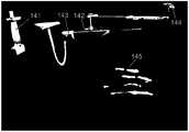
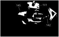
- FIG. 2Ais a block diagram of an optical tracking system according to an embodiment.
- the optical tracking system 1 for medical appliancesincludes a plurality of optical markers 11, a plurality of optical sensors 12, and a computer device 13.
- the optical markers 11are arranged on one or more medical appliances, and here are a plurality of medical appliances 21 ⁇ 24 description as an example, the optical marker 11 can also be set on the surgical target object 3, the medical appliances 21-24 and the surgical target object 3 are placed on the platform 4, and the optical sensor 12 optically senses the optical marker 11 to Generate multiple sensing signals respectively.
- the computer device 13is coupled to the optical sensor 12 to receive the sensing signal, and has a three-dimensional model 14 of the surgical situation, and adjusts the three-dimensional model 14 of the surgical situation according to the sensing signal among the medical appliance presents 141-144 and the surgical target present 145 The relative position between.
- the medical appliance presenting objects 141 to 144 and the surgical target presenting object 145are shown in FIG. 2D, which represent the medical appliances 21 to 24 and the surgical target object 3 in the three-dimensional model 14 of the operation situation.
- the three-dimensional model 14 of the surgical situationcan obtain the current positions of the medical appliances 21-24 and the surgical target object 3 and reflect the medical appliance presentation and the surgical target presentation accordingly.
- FIG. 2Bis a schematic diagram of the optical tracking system of the embodiment.
- Four optical sensors 121 to 124are installed on the ceiling and face the optical markers 11, medical appliances 21 to 24, and Surgical target object 3.
- the medical tool 21is a medical probe, such as a probe for ultrasonic imaging detection or other devices that can detect the inside of the surgical target object 3. These devices are actually used clinically, and the probe for ultrasonic imaging detection is, for example, ultrasound. Transducer (Ultrasonic Transducer).
- the medical appliances 22-24are surgical appliances, such as needles, scalpels, hooks, etc., which are actually used clinically. If used for surgical training, the medical probe can be a device that is actually used in clinical practice or a clinically simulated device, and the surgical instrument can be a device that is actually used in clinical practice or a simulated device that simulates clinical practice.
- Figure 2Cis a schematic diagram of the optical tracking system of the embodiment.
- the medical appliances 21-24 and the surgical target 3 on the platform 4are used for surgical training, such as minimally invasive finger surgery, which can be used for triggers. Refers to treatment surgery.
- the material of the clamps of the platform 4 and the medical appliances 21-24can be wood.
- the medical appliance 21is a realistic ultrasonic transducer (or probe), and the medical appliance 22-24 includes a plurality of surgical instruments, such as expanders ( dilator, needle, and hook blade.
- the surgical target 3is a hand phantom.
- Three or four optical markers 11are installed on each medical appliance 21-24, and three or four optical markers 11 are also installed on the surgical target object 3.
- the computer device 13is connected to the optical sensor 12 to track the position of the optical marker 11 in real time.
- optical markers 11There are 17 optical markers 11, including 4 that are linked on or around the surgical target object 3, and 13 optical markers 11 are on medical appliances 21-24.
- the optical sensor 12continuously transmits real-time information to the computer device 13.
- the computer device 13also uses the movement judgment function to reduce the calculation burden. If the moving distance of the optical marker 11 is less than the threshold value, the position of the optical marker 11 Without updating, the threshold value is, for example, 0.7 mm.
- the computer device 13includes a processing core 131, a storage element 132, and a plurality of I/O interfaces 133, 134.
- the processing core 131is coupled to the storage element 132 and the I/O interfaces 133, 134.
- the I/O interface 133can receive optical sensing.
- the detection signal generated by the detector 12communicates with the output device 5 through the I/O interface 134, and the computer device 13 can output the processing result to the output device 5 through the I/O interface 134.
- the I/O interfaces 133 and 134are, for example, peripheral transmission ports or communication ports.
- the output device 5is a device capable of outputting images, such as a display, a projector, a printer, and so on.
- the storage element 132stores program codes for execution by the processing core 131.
- the storage element 132includes a non-volatile memory and a volatile memory.
- the non-volatile memoryis, for example, a hard disk, a flash memory, a solid state disk, an optical disk, and so on.
- the volatile memoryis, for example, dynamic random access memory, static random access memory, and so on.
- the program codeis stored in the non-volatile memory, and the processing core 131 can load the program code from the non-volatile memory to the volatile memory, and then execute the program code.
- the storage component 132stores the program code and data of the operation situation three-dimensional model 14 and the tracking module 15, and the processing core 131 can access the storage component 132 to execute and process the operation situation three-dimensional model 14 and the program code and data of the tracking module 15.
- the processing core 131is, for example, a processor, a controller, etc., and the processor includes one or more cores.
- the processormay be a central processing unit or a graphics processor, and the processing core 131 may also be the core of a processor or a graphics processor.
- the processing core 131may also be a processing module, and the processing module includes multiple processors.
- the operation of the optical tracking systemincludes the connection between the computer device 13 and the optical sensor 12, pre-operation procedures, coordinate correction procedures of the optical tracking system, real-time rendering procedures, etc.
- the tracking module 15represents the correlation of these operations
- the storage element 132 of the computer device 13stores the tracking module 15, and the processing core 131 executes the tracking module 15 to perform these operations.
- the computer device 13performs the pre-work and the coordinate correction of the optical tracking system to find the optimized conversion parameters, and then the computer device 13 can set the medical appliance presentations 141-144 and the operation according to the optimized conversion parameters and sensing signals The position of the target presentation 145 in the three-dimensional model 14 of the surgical situation.
- the computer device 13can deduce the position of the medical appliance 21 inside and outside the surgical target object 3, and adjust the relative position between the medical appliance presenting objects 141 to 144 and the surgical target presenting object 145 in the three-dimensional model 14 of the operation situation accordingly.
- the medical appliances 21-24can be tracked in real time from the detection results of the optical sensor 12 and correspondingly presented in the three-dimensional model 14 of the surgical context.
- the representation of the three-dimensional model 14 in the surgical contextis shown in FIG. 2D.
- the three-dimensional model 14 of the operation situationis a native model, which includes models established for the surgical target object 3 and also includes models established for the medical appliances 21-24.
- the method of establishmentcan be that the developer directly uses computer graphics technology to construct it on the computer, such as using drawing software or special application development software.
- the computer device 13can output the display data 135 to the output device 5.
- the display data 135is used to present 3D images of the medical appliance presentation objects 141-144 and the surgical target presentation object 145.
- the output device 5can output the display data 135.
- the output methodis, for example, Display or print, etc. The result of outputting in display mode is shown in FIG. 2D, for example.
- the coordinate position of the three-dimensional model 14 of the surgical situationcan be accurately transformed to correspond to the optical marker 11 in the tracking coordinate system, and vice versa.
- the medical appliances 21-24 and the surgical target object 3can be tracked in real time based on the detection result of the optical sensor 12, and the positions of the medical appliances 21-24 and the surgical target object 3 in the tracking coordinate system can be obtained after the aforementioned processing.
- the medical appliance presentation objects 141-144correspond to the surgical target presentation object 145 accurately.
- the medical appliance presentation objects 141-144correspond to the surgery The target presentation 145 will move immediately following the three-dimensional model 14 of the operation situation.
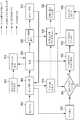
- Fig. 3is a functional block diagram of a surgical training system according to an embodiment.
- the operation information real-time presentation systemcan be used in the operation training system, and the server 7 can perform the blocks shown in FIG. 3.
- multiple functionscan be programmed into multi-threaded execution. For example, there are four threads in Figure 3, which are the main thread for calculation and drawing, the thread for updating marker information, the thread for transmitting images, and the thread for scoring.
- the main thread of calculation and drawingincludes block 902 to block 910.
- the program of the main threadstarts to execute, and in block 904, the UI event listener starts other threads for the event or further executes other blocks of the main thread.
- the optical tracking systemwill be calibrated, and then in block 908, the subsequent image to be rendered is calculated, and then in block 910, the image is rendered by OpenGL.
- the thread for updating the marker informationincludes block 912 to block 914.
- the thread for updating the marker information opened from the block 904first connects the server 7 to the components of the optical tracking system, such as an optical sensor, in block 912, and then updates the marker information in block 914. Between block 906 and block 906, these two threads share memory to update the marker information.
- the thread for transmitting the imageincludes block 916 to block 920.
- the thread for transmitting the image started in block 904will start the transmission server in block 916, and then in block 918 it will get the rendered image from block 908 and compose the bmp image and compress it into jpeg, and then transmit the image in block 920 To the display device.
- the scoring threadincludes blocks 922 to 930.
- the scoring thread started in block 904starts in block 922, and in block 924, it is confirmed that the training phase is completed or manually stopped. If it is completed, enter block 930 to stop the scoring thread. If only the trainee manually stops, enter the block 926.
- the marker informationis obtained from block 906 and the current training phase information is sent to the display device.
- the scoring conditions of the stageare confirmed, and then return to block 924.
- Fig. 4is a block diagram of a training system for medical appliance operation according to an embodiment.
- the training system for medical appliance operation(hereinafter referred to as the training system) can truly simulate the surgical training environment.
- the training systemincludes an optical tracking system 1a, one or more medical appliances 21-24, and the surgical target object 3.
- the optical tracking system 1aincludes a plurality of optical markers 11, a plurality of optical sensors 12, and a computer device 13.
- the optical markers 11are arranged on medical appliances 21-24 and surgical target objects 3, medical appliances 21-24 and surgical target objects 3 Place on the platform 4.
- the medical appliancepresents 141 to 144 and the surgical target presents 145 are correspondingly presented on the three-dimensional model 14a of the surgical context.
- the medical tools 21-24include medical probes and surgical tools.
- the medical tools 21are medical probes
- the medical tools 22-24are surgical tools.
- the medical appliance presentations 141-144include medical probe presentations and surgical appliance presentations.
- the medical appliance presentation 141is a medical probe presentation
- the medical appliance presentations 142-144are surgical appliance presentations.
- the storage component 132stores the program code and data of the operation situation three-dimensional model 14a and the tracking module 15, and the processing core 131 can access the storage component 132 to execute and process the operation situation three-dimensional model 14a and the program code and data of the tracking module 15.
- the surgical target object 3is an artificial limb, such as artificial upper limbs, hand phantoms, artificial palms, artificial fingers, artificial arms, artificial upper arms, artificial forearms, artificial elbows, artificial upper limbs, artificial feet, artificial toes, artificial ankles, artificial Calf, false thigh, false knee, false torso, false neck, false head, false shoulder, false chest, false abdomen, false waist, false hip or other false parts, etc.
- artificial upper limbssuch as artificial upper limbs, hand phantoms, artificial palms, artificial fingers, artificial arms, artificial upper arms, artificial forearms, artificial elbows, artificial upper limbs, artificial feet, artificial toes, artificial ankles, artificial Calf, false thigh, false knee, false torso, false neck, false head, false shoulder, false chest, false abdomen, false waist, false hip or other false parts, etc.
- the training systemtakes the minimally invasive surgery training of the fingers as an example.
- the surgeryis a trigger finger treatment operation
- the surgical target object 3is a prosthetic hand
- the medical probe 21is a realistic ultrasonic transducer (or probe).
- the surgical instruments 22-24are a needle, a dilator, and a hook blade.
- other surgical target objects 3may be used for other surgical training.
- the storage element 132also stores the program codes and data of the physical medical image 3D model 14b, the artificial medical image 3D model 14c, and the training module 16.
- the processing core 131can access the storage element 132 to execute and process the physical medical image 3D model 14b and artificial medicine.
- the training module 16is responsible for the following surgical training procedures and the processing, integration and calculation of related data.
- FIG. 5Ais a schematic diagram of a three-dimensional model of an operation scenario according to an embodiment
- FIG. 5Bis a schematic diagram of a physical medical image three-dimensional model according to an embodiment
- FIG. 5Cis an artificial medical image according to an embodiment. Schematic of the three-dimensional model.
- the content of these three-dimensional modelscan be output or printed by the output device 5.
- the solid medical image three-dimensional model 14bis a three-dimensional model established from medical images, which is a model established for the surgical target object 3, such as the three-dimensional model shown in FIG. 5B.
- the medical imageis, for example, a computer tomography image, and the image of the surgical target object 3 actually generated after the computer tomography is used to build the three-dimensional model 14b of the physical medical image.
- the artificial medical image three-dimensional model 14ccontains an artificial medical image model.
- the artificial medical image modelis a model established for the surgical target object 3, such as the three-dimensional model shown in FIG. 5C.
- the artificial medical imaging modelis a three-dimensional model of artificial ultrasound imaging. Since the surgical target 3 is not a real living body, although computer tomography can obtain images of the physical structure, it is still possible to use other medical imaging equipment such as ultrasound imaging. Effective or meaningful images cannot be obtained directly from the surgical target object 3. Therefore, the ultrasound image model of the surgical target object 3 must be artificially generated. Selecting an appropriate position or plane from the three-dimensional model of artificial ultrasound images can generate two-dimensional artificial ultrasound images.
- the computer device 13generates a medical image 136 according to the three-dimensional model 14a of the surgical situation and the medical image model.
- the medical image modelis, for example, a solid medical image three-dimensional model 14b or an artificial medical image three-dimensional model 14c.
- the computer device 13generates a medical image 136 based on the three-dimensional model 14a of the surgical situation and the three-dimensional model 14c of an artificial medical image.
- the medical image 136is a two-dimensional artificial ultrasound image.
- the computer device 13scores the detection object found by the medical probe 141 and the operation of the surgical instrument representation 145, such as a specific surgical site.
- 6A to 6Dare schematic diagrams of the direction vector of the medical appliance according to an embodiment.
- the direction vectors of the medical device presentation objects 141-144 corresponding to the medical devices 21-24will be rendered instantly.
- the direction vector of the medical probecan be calculated by calculating the center of gravity of the optical marker And get, and then project from another point to the xz plane, and calculate the vector from the center of gravity to the projection point.
- Other medical appliance presentations 142-144are relatively simple, and the direction vector can be calculated using the sharp points in the model.
- the training systemcan only draw the model of the area where the surgical target presenting object 145 is located instead of drawing all the medical appliance presenting objects 141-144.
- the transparency of the skin modelcan be adjusted to observe the internal anatomical structure of the surgical target present 145, and to see ultrasound image slices or computer tomography image slices of different cross-sections, such as horizontal cross-sections. plane or axial plane), sagittal plane (sagittal plane) or coronal plane (coronal plane), which can help the operator during the operation.
- the bounding boxes of each modelare constructed to detect collisions.
- the surgical training systemcan determine which medical appliances have contacted tendons, bones and/or skin, and can determine when to start scoring.
- the optical marker 11 attached to the surgical target object 3must be clearly seen or detected by the optical sensor 12. If the optical marker 11 is covered, the position of the optical marker 11 is detected The accuracy of is reduced, and the optical sensor 12 needs at least two to see all the optical markers at the same time.
- the calibration procedureis as described above, for example, three-stage calibration, which is used to accurately calibrate two coordinate systems.
- the correction error, the iteration count, and the final position of the optical markercan be displayed in the window of the training system, for example, by the output device 5.
- the accuracy and reliability informationcan be used to remind users that the system needs to be recalibrated when the error is too large.
- the three-dimensional modelis drawn at a frequency of 0.1 times per second, and the drawn result can be output to the output device 5 for display or printing.
- the usercan start the surgical training process.
- the training processfirst use a medical probe to find the site to be operated on. After finding the site to be operated on, the site is anesthetized. Then, expand the path from the outside to the surgical site, and after expansion, the scalpel is deepened along this path to the surgical site.
- FIGS. 7A to 7Dare schematic diagrams of the training process of the training system of an embodiment.
- the surgical training processincludes four stages and is illustrated by taking minimally invasive surgery training of fingers as an example.
- the medical probe 21is used to find the site to be operated on, so as to confirm that the site to be operated on is in the training system.
- the surgical siteis, for example, the pulley area (pulley), which can be judged by looking for the position of the metacarpophalangeal joints, the anatomical structures of the bones and tendons of the fingers, and the focus at this stage is whether the first pulley area (A1 pulley) is found.
- the training systemwill automatically enter the next stage of scoring.
- the medical probe 21is placed on the skin and kept in contact with the skin at the metacarpal joints (MCP joints) along the midline of the flexor tendon.
- the surgical instrument 22is used to open the path of the surgical area.
- the surgical instrument 22is, for example, a needle.
- the needleis inserted to inject local anesthetic and expand the space.
- the process of inserting the needlecan be performed under the guidance of continuous ultrasound images.
- This continuous ultrasound imageis an artificial ultrasound image, which is the aforementioned medical image 136. Because it is difficult to simulate regional anesthesia with prosthetic hands, anesthesia is not specifically simulated.
- the surgical instrument 23is pushed in along the same path as the surgical instrument 22 in the second stage to create the trajectory required for hooking the knife in the next stage.
- the surgical instrument 23is, for example, a dilator.
- the training systemwill automatically enter the next stage of scoring.
- the surgical instrument 24is inserted along the trajectory created in the third stage, and the pulley is divided by the surgical instrument 24.
- the surgical instrument 24is, for example, a hook blade.
- the focus of the third stageis similar to that of the fourth stage.
- the vessels and nerves near both sides of the flexor tendonmay be easily miscut. Therefore, the third stage and the fourth stage
- the focus of the stageis not only not touching the tendons, nerves and blood vessels, but also opening a track that is at least 2mm larger than the first pulley area, so as to leave space for the hook knife to cut the pulley area.
- the operations of each training phasemust be quantified.
- the operation area during the operationis defined by the finger anatomy as shown in Figure 8A, which can be divided into an upper boundary and a lower boundary. Because most of the tissue on the tendon is fat and does not cause pain, the upper boundary of the surgical area can be defined by the skin of the palm, and the lower boundary is defined by the tendon.
- the proximal depth boundaryis 10mm (average length of the first trochlear zone) from the metacarpal head-neck joint.
- the distal depth boundaryis not important, because it has nothing to do with tendons, blood vessels, and nerves.
- the left and right boundariesare defined by the width of the tendon, and nerves and blood vessels are located on both sides of the tendon.
- the scoring method for each training stageis as follows.
- the focus of the trainingis to find the target, such as the target to be excised.
- the targetsuch as the target to be excised.
- the first pulley areaA1pulley.
- the angle between the medical probe and the bone spindleshould be close to vertical, and the allowable angle deviation is ⁇ 30°. Therefore, the scoring formula for the first stage is as follows:
- the first stage scorethe score of the target object ⁇ its weight + the angle score of the probe ⁇ its weight
- the focus of trainingis to use the needle to open the path of the surgical area. Since the pulley area surrounds the tendon, the distance between the main axis of the bone and the needle should be small. Therefore, the calculation formula for the second stage scoring is as follows:
- Second stage scoreopening score ⁇ its weight + needle angle score ⁇ its weight + distance from the main axis of the bone score ⁇ its weight
- the focus of trainingis to insert a dilator that enlarges the surgical area into the finger.
- the trajectory of the dilatormust be close to the main axis of the bone.
- the angle between the expander and the main axis of the boneshould be approximately parallel, and the allowable angle deviation is ⁇ 30°. Due to the space left for the hook knife to cut the first trolley area, the expander must be at least 2mm higher than the first trolley area.
- the third stage scorehigher than the pulley area score ⁇ its weight + expander angle score ⁇ its weight + distance from the main axis of the bone score ⁇ its weight + not leaving the surgical area score ⁇ its weight
- the scoring conditionsare similar to those in the third stage, except that the hook needs to be rotated 90°. This rule is added to the scoring at this stage.
- the scoring formulais as follows:
- the fourth stage scorehigher than the pulley area score ⁇ its weight + hook angle score ⁇ its weight + distance from the main axis of the bone score ⁇ its weight + not leaving the surgical area score ⁇ its weight + rotating hook score ⁇ its weight
- this calculation methodis the same as calculating the angle between the palm normal and the direction vector of the medical appliance.
- this calculation methodis the same as calculating the angle between the palm normal and the direction vector of the medical appliance.
- PCAprincipal component analysis
- the longest axisis taken as the main axis of the bone.
- the shape of the bone in the computer tomography imageis not uniform, which causes the axis found by the principal component analysis and the palm normal line to be not perpendicular to each other.
- the skin on the bonecan be used to find the palm normal using principal component analysis. Then, the angle between the bone spindle and the medical appliance can be calculated.
- the distance between the bone main axis and the medical appliancealso needs to be calculated.
- the distance calculationis similar to calculating the distance between the top and the plane of the medical appliance.
- the planerefers to the plane containing the bone main axis vector vector and the palm normal.
- the schematic diagram of distance calculationis shown in Figure 8D. This plane can be obtained by the cross product of the palm normal vector D2 and the bone principal axis vector D1. Since these two vectors can be obtained in the previous calculation, the distance between the main axis of the bone and the appliance can be easily calculated.
- FIG. 8Eis a schematic diagram of an artificial medical image according to an embodiment, and the tendon section and the skin section in the artificial medical image are marked with dotted lines.
- the tendon section and the skin sectioncan be used to construct the model and the bounding box, the bounding box is used for collision detection, and the pulley area can be defined in the static model.
- collision detectionit is possible to determine the surgical area and determine whether the medical appliance crosses the pulley area.
- the average length of the first pulley areais about 1mm, and the first pulley area is located at the proximal end of the metacarpal head-neck (MCP) joint.
- MCPmetacarpal head-neck
- the average thickness of the pulley areais about 0.3mm and surrounds the tendons.
- Fig. 9Ais a flow chart of generating artificial medical images according to an embodiment. As shown in FIG. 9A, the generated flow includes step S21 to step S24.
- Step S21is to extract the first set of bone skin features from the cross-sectional image data of the artificial limb.
- the artificial limbis the aforementioned surgical target object 3, which can be used as a limb for minimally invasive surgery training, such as a prosthetic hand.
- the cross-sectional image dataincludes multiple cross-sectional images, and the cross-sectional reference image is a computed tomography image or a solid cross-sectional image.
- Step S22is to extract the second set of bone skin features from the medical image data.
- the medical image datais a three-dimensional ultrasound image, such as the three-dimensional ultrasound image of FIG. 9B, which is created by multiple planar ultrasound images.
- Medical image dataare medical images taken of real organisms, not artificial limbs.
- the first group of bone skin features and the second group of bone skin featuresinclude multiple bone feature points and multiple skin feature points.
- Step S23is to establish feature registration data (registration) based on the first set of bone and skin features and the second set of bone and skin features.
- Step S23includes: taking the first set of bone-skin features as a reference target (target); finding out the correlation function as the spatial alignment correlation data, where the correlation function satisfies the second set of bone-skin features to align with the reference target without being due to the first set of bones Disturbance caused by skin features and the second set of bone skin features.
- the correlation functionis found through the algorithm of the maximum likelihood estimation problem (maximum likelihood estimation problem) and the maximum expectation algorithm (EM Algorithm).
- Step S24is to perform deformation processing on the medical image data according to the feature alignment data to generate artificial medical image data suitable for artificial limbs.
- the artificial medical image datais, for example, a three-dimensional ultrasound image, which still retains the characteristics of the organism in the original ultrasound image.
- Step S24includes: generating a deformation function based on the medical image data and feature alignment data; applying a grid to the medical image data and obtaining multiple dot positions accordingly; deforming the dot positions according to the deformation function; based on the deformed dot positions,
- the medical image datais supplemented with corresponding pixels to generate a deformed image, and the deformed image is used as artificial medical image data.
- the deformation functionis generated using the moving least square (MLS) method.
- the deformed imageis generated using affine transform.
- step S21 to step S24by capturing the image characteristics of the real ultrasonic image and the artificial hand computer tomography image, the corresponding point relationship of the deformation is obtained by image registration, and then the ultrasonic image close to the real human is generated based on the artificial hand through the deformation
- the ultrasoundretains the characteristics of the original live ultrasound image.
- the artificial medical image datais a three-dimensional ultrasound image, a plane ultrasound image of a specific position or a specific section can be generated based on the corresponding position or section of the three-dimensional ultrasound image.
- FIG. 10A and FIG. 10Bare schematic diagrams of the correction of the artificial hand model and the ultrasonic volume according to an embodiment.
- the physical medical image 3D model 14b and the artificial medical image 3D model 14care related to each other. Since the model of the prosthetic hand is constructed by the computed tomographic image volume, the positional relationship between the computed tomographic image volume and the ultrasound volume can be directly used to integrate the artificial hand. Establish correlation with ultrasound volume.
- FIG. 10Cis a schematic diagram of ultrasonic volume and collision detection according to an embodiment
- FIG. 10Dis a schematic diagram of an artificial ultrasound image according to an embodiment.
- the training systemmust be able to simulate a real ultrasonic transducer (or probe) to generate slice image fragments from the ultrasonic volume. Regardless of the angle of the transducer (or probe), the simulated transducer (or probe) must depict the corresponding image segment.
- the angle between the medical probe 21 and the ultrasonic bodyis first detected. Then, the collision detection of the segment surface is based on the width of the medical probe 21 and the ultrasonic volume, which can be used to find the corresponding image segment being drawn.
- the resulting imageis shown in Figure 10D.
- the artificial medical image datais a three-dimensional ultrasound image
- the three-dimensional ultrasound imagehas a corresponding ultrasound volume
- the content of the image segment to be depicted by the simulated transducer (or probe)can be generated according to the corresponding position of the three-dimensional ultrasound image.
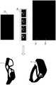
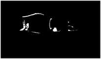
- FIG. 11A and FIG. 11Bare schematic diagrams of an operation training system according to an embodiment.
- Surgery traineesoperate medical appliances, and the medical appliances can be correspondingly displayed on the display device in real time.
- FIGS. 12A and 12Bare schematic diagrams of images of the training system according to an embodiment.
- Operation traineesoperate medical appliances.
- the current artificial ultrasound imagescan also be displayed in real time.
- the surgical wearable image display device and the surgical information real-time presentation system of the present disclosurecan assist or train users to operate medical instruments.
- the training system of the present disclosurecan provide a realistic surgical training environment for trainees, thereby effectively Assist trainees to complete surgical training.
- the surgical performercan also perform a simulated operation on the prosthesis first, and use the surgical wearable image display device and the surgical information real-time display system to review or review the simulated surgery performed in advance before the actual operation, so that the surgical performer Can quickly grasp the key points of surgery or points that need attention.
- surgical wearable image display devices and surgical information real-time display systemscan also be applied to actual surgical procedures.
- Medical imagessuch as ultrasound images are transmitted to surgical wearable image display devices such as smart glasses. This display method It can make the operator no longer need to turn his head to look at the screen.
Landscapes
- Engineering & Computer Science (AREA)
- Health & Medical Sciences (AREA)
- Theoretical Computer Science (AREA)
- Physics & Mathematics (AREA)
- Surgery (AREA)
- Life Sciences & Earth Sciences (AREA)
- Animal Behavior & Ethology (AREA)
- Data Mining & Analysis (AREA)
- Medical Informatics (AREA)
- Molecular Biology (AREA)
- Biomedical Technology (AREA)
- General Health & Medical Sciences (AREA)
- Public Health (AREA)
- Veterinary Medicine (AREA)
- Robotics (AREA)
- Heart & Thoracic Surgery (AREA)
- Databases & Information Systems (AREA)
- Mathematical Physics (AREA)
- Software Systems (AREA)
- General Engineering & Computer Science (AREA)
- General Physics & Mathematics (AREA)
- Nuclear Medicine, Radiotherapy & Molecular Imaging (AREA)
- Processing Or Creating Images (AREA)
Abstract
Description
Translated fromChinese本发明涉及一种穿戴式影像显示装置及呈现系统,特别涉及一种手术用穿戴式影像显示装置及手术资讯即时呈现系统。The invention relates to a wearable image display device and a presentation system, in particular to a wearable image display device for surgery and a real-time presentation system of surgery information.
医疗器具的操作训练需要花一段时间才能让学习的使用者能够熟练,以微创手术来说,除了操作手术刀之外通常还会操作超声波影像的探头,微创手术所能容许的误差不大,通常要有丰富的经验才能顺利的进行,因此,手术前的训练格外重要。另外,医师进行手术时若要转头看医疗设备显示的影像,这对手术的进行也造成不便。It takes some time to train the operation of medical devices to make the learners become proficient. For minimally invasive surgery, in addition to operating a scalpel, ultrasound imaging probes are usually operated. The tolerance for minimally invasive surgery is not large. It usually takes a wealth of experience to proceed smoothly. Therefore, training before surgery is extremely important. In addition, if the doctor turns his head to look at the image displayed by the medical device when performing an operation, this also causes inconvenience to the operation.
因此,如何提供一种手术用穿戴式影像显示装置及手术资讯即时呈现系统,可以协助或训练医师操作医疗器具,已成为重要课题之一。Therefore, how to provide a wearable image display device for surgery and a real-time presentation system for surgery information that can assist or train physicians to operate medical instruments has become one of the important issues.
发明内容Summary of the invention
有鉴于上述课题,本发明的目的为提供一种手术用穿戴式影像显示装置及手术资讯即时呈现系统,能协助或训练使用者操作医疗器具。In view of the above-mentioned problems, the purpose of the present invention is to provide a surgical wearable image display device and a real-time surgical information presentation system, which can assist or train users to operate medical instruments.
一种手术用穿戴式影像显示装置包含显示器、无线接收器以及处理核心。无线接收器无线地即时接收医学影像或医疗用具资讯;处理核心耦接无线接收器与显示器,以将医学影像或医疗用具资讯显示于显示器。A wearable image display device for surgery includes a display, a wireless receiver, and a processing core. The wireless receiver wirelessly receives medical images or medical device information in real time; the processing core is coupled to the wireless receiver and the display to display the medical images or medical device information on the display.
在一个实施例中,医学影像为人造肢体的人造医学影像。In one embodiment, the medical image is an artificial medical image of an artificial limb.
在一个实施例中,手术用穿戴式影像显示装置为智慧眼镜或头戴式显示器。In one embodiment, the surgical wearable image display device is smart glasses or a head-mounted display.
在一个实施例中,医疗用具资讯包括位置资讯以及角度资讯。In one embodiment, the medical appliance information includes location information and angle information.
在一个实施例中,无线接收器无线地即时接收手术目标物资讯,处理核心将医学影像、医疗用具资讯或手术目标物资讯显示于显示器。In one embodiment, the wireless receiver wirelessly receives the surgical target information in real time, and the processing core displays the medical image, medical appliance information, or surgical target information on the display.
在一个实施例中,手术目标物资讯包括位置资讯以及角度资讯。In one embodiment, the surgical target information includes position information and angle information.
在一个实施例中,无线接收器无线地即时接收手术导引视讯,处理核心将医学影像、医疗用具资讯或手术导引视讯显示于显示器。In one embodiment, the wireless receiver wirelessly receives the surgical guidance video in real time, and the processing core displays the medical image, medical appliance information or the surgical guidance video on the display.
一种手术资讯即时呈现系统包含如前所述的手术用穿戴式影像显示装置以及服务器。服务器与无线接收器无线地连线,无线地即时传送医学影像以及医疗用具资讯。A real-time presentation system for surgical information includes the aforementioned surgical wearable image display device and a server. The server and the wireless receiver are connected wirelessly to wirelessly transmit medical images and medical device information in real time.
在一个实施例中,服务器通过两个网络端口分别传送医学影像以及医疗用具资讯。In one embodiment, the server transmits medical images and medical device information through two network ports, respectively.
在一个实施例中,系统更包含光学定位装置,光学定位装置检测医疗用具的位置并产生定位信号,其中服务器根据定位信号产生医疗用具资讯。In one embodiment, the system further includes an optical positioning device. The optical positioning device detects the position of the medical appliance and generates a positioning signal. The server generates medical appliance information according to the positioning signal.
承上所述,本公开的手术用穿戴式影像显示装置及手术资讯即时呈现系统能协助或训练使用者操作医疗器具,本公开的训练系统能提供受训者拟真的手术训练环境,藉以有效地辅助受训者完成手术训练。In summary, the surgical wearable image display device and surgical information real-time presentation system of the present disclosure can assist or train users to operate medical instruments. The training system of the present disclosure can provide trainees with a realistic surgical training environment, thereby effectively Assist trainees to complete surgical training.
另外,手术执行者也可以先在假体上做模拟手术,并且在实际手术开始前再利用手术用穿戴式影像显示装置及手术资讯即时呈现系统回顾或复习预先做的模拟手术,以便手术执行者能快速掌握手术的重点或需注意的要点。In addition, the surgical performer can also perform a simulated operation on the prosthesis first, and use the surgical wearable image display device and the surgical information real-time display system to review or review the simulated surgery performed in advance before the actual operation, so that the surgical performer Can quickly grasp the key points of surgery or points that need attention.
再者,手术用穿戴式影像显示装置及手术资讯即时呈现系统也可应用在实际手术过程,例如超音波影像等的医学影像传送到例如智慧眼镜的手术用穿戴式影像显示装置,这样的显示方式可以让手术执行者不再需要转头看屏幕。Furthermore, surgical wearable image display devices and surgical information real-time display systems can also be applied to actual surgical procedures. Medical images such as ultrasound images are transmitted to surgical wearable image display devices such as smart glasses. This display method It can make the operator no longer need to turn his head to look at the screen.
图1A为一个实施例的手术资讯即时呈现系统的区块图。FIG. 1A is a block diagram of an embodiment of a real-time presentation system for surgical information.
图1B为图1A中手术用穿戴式影像显示装置接收医学影像或医疗用具资讯的示意图。FIG. 1B is a schematic diagram of the wearable image display device for surgery in FIG. 1A receiving medical images or medical device information.
图1C为图1A中服务器与手术用穿戴式影像显示装置的传输的示意图。FIG. 1C is a schematic diagram of the transmission between the server and the surgical wearable image display device in FIG. 1A.
图1D为图1A中服务器通过两个网络端口传输的示意图。Figure 1D is a schematic diagram of the server in Figure 1A transmitting through two network ports.
图2A为一个实施例的光学追踪系统的区块图。Fig. 2A is a block diagram of an optical tracking system according to an embodiment.
图2B与图2C为一个实施例的光学追踪系统的示意图。2B and 2C are schematic diagrams of an optical tracking system according to an embodiment.
图2D为一个实施例的手术情境三维模型的示意图。Fig. 2D is a schematic diagram of a three-dimensional model of a surgical situation in an embodiment.
图3为一个实施例的手术训练系统的功能区块图。Fig. 3 is a functional block diagram of a surgical training system according to an embodiment.
图4为一个实施例的医疗用具操作的训练系统的区块图。Fig. 4 is a block diagram of a training system for medical appliance operation according to an embodiment.
图5A为一个实施例的手术情境三维模型的示意图。Fig. 5A is a schematic diagram of a three-dimensional model of a surgical scenario according to an embodiment.
图5B为一个实施例的实体医学影像三维模型的示意图。FIG. 5B is a schematic diagram of a three-dimensional model of an entity medical image according to an embodiment.
图5C为一个实施例的人造医学影像三维模型的示意图。FIG. 5C is a schematic diagram of a three-dimensional model of an artificial medical image according to an embodiment.
图6A至图6D为一个实施例的医疗用具的方向向量的示意图。6A to 6D are schematic diagrams of the direction vector of the medical appliance according to an embodiment.
图7A至图7D为一个实施例的训练系统的训练过程示意图。7A to 7D are schematic diagrams of the training process of the training system in an embodiment.
图8A为一个实施例的手指结构的示意图。Fig. 8A is a schematic diagram of a finger structure according to an embodiment.
图8B为一个实施例从电脑断层摄影影像在骨头上采用主成分分析的示意图。Fig. 8B is a schematic diagram of applying principal component analysis on bones from computed tomography images in an embodiment.
图8C为一个实施例从电脑断层摄影影像在皮肤上采用主成分分析的示意图。FIG. 8C is a schematic diagram of applying principal component analysis on the skin from a computed tomography image in an embodiment.
图8D为一个实施例计算骨头主轴与算医疗用具间的距离的示意图。Fig. 8D is a schematic diagram of calculating the distance between the bone spindle and the medical appliance in an embodiment.
图8E为一个实施例的人造医学影像的示意图。Fig. 8E is a schematic diagram of an artificial medical image according to an embodiment.
图9A为一个实施例的产生人造医学影像的区块图。FIG. 9A is a block diagram for generating artificial medical images according to an embodiment.
图9B为一个实施例的人造医学影像的示意图。Fig. 9B is a schematic diagram of an artificial medical image according to an embodiment.
图10A与图10B为一个实施例的假手模型与超声波容积的校正的示意图。10A and 10B are schematic diagrams of the artificial hand model and the correction of ultrasonic volume according to an embodiment.
图10C为一个实施例的超声波容积以及碰撞检测的示意图。Fig. 10C is a schematic diagram of ultrasonic volume and collision detection in an embodiment.
图10D为一个实施例的人造超声波影像的示意图。FIG. 10D is a schematic diagram of an artificial ultrasound image according to an embodiment.
图11A与图11B为一个实施例的操作训练系统的示意图。11A and 11B are schematic diagrams of an operation training system according to an embodiment.
图12A与图12B为一个实施例的训练系统的影像示意图。12A and 12B are schematic diagrams of images of the training system according to an embodiment.
以下将参照相关附图,说明依本发明优选实施例的手术用穿戴式影像显示装置及手术资讯即时呈现系统,其中相同的元件将以相同的附图标记加以说明。Hereinafter, the wearable image display device for surgery and the real-time presentation system for surgery information according to the preferred embodiment of the present invention will be described with reference to the relevant drawings, in which the same components will be described with the same reference numerals.
如图1A所示,图1A为一个实施例的手术资讯即时呈现系统的区块图。手术资讯即时呈现系统包含手术用穿戴式影像显示装置6(以下简称显示装置6)以及服务器7。显示装置6包含处理核心61、无线接收器62、显示器63以及储存元件64。无线接收器62无线地即时接收医学影像721或医疗用具资讯722。处理核心61耦接储存元件64,处理核心61耦接无线接收器62与显示器63,以将医学影像721或医疗用具资讯722显示于显示器63。服务器7包含处理核心71、输出入界面72、输出入界面74以及储存元件73。处理核心71耦接输出入界面72、输出入界面74以及储存元件73,服务器7与无线接收器62无线地连线,无线地即时传送医学影像721以及医疗用具资讯722。另外,手术资讯即时呈现系统还可包含显示装置8,服务器7还可通过输出入界面74将资讯输出到显示装置8来显示。As shown in FIG. 1A, FIG. 1A is a block diagram of a real-time presentation system for surgical information according to an embodiment. The surgical information real-time presentation system includes a surgical wearable image display device 6 (hereinafter referred to as the display device 6) and a
处理核心61、71例如是处理器、控制器等等,处理器包括或多个核心。处理器可以是中央处理器或图型处理器,处理核心61、71也可以是处理器或图型处理器的核心。另一方面,处理核心61、71也可以是一个处理模块,处理模块包括多个处理器。The
储存元件64、73储存程序码以供处理核心61、71执行,储存元件64、73包括非挥发性存储器及挥发性存储器,非挥发性存储器例如是硬碟、快闪存储器、固态碟、光碟片等等。挥发性存储器例如是动态随机存取存储器、静态随 机存取存储器等等。举例来说,程序码储存于非挥发性存储器,处理核心61、71可将程序码从非挥发性存储器载入到挥发性存储器,然后执行程序码。The
另外,无线接收器62可无线地即时接收手术目标物资讯723,处理核心61可将医学影像721、医疗用具资讯722或手术目标物资讯723显示于显示器63。另外,无线接收器62可无线地即时接收手术导引视讯724,处理核心61将医学影像721、医疗用具资讯722或手术导引视讯724显示于显示器63。医学影像、医疗用具资讯、手术目标物资讯或手术导引视讯可以导引或提示使用者进行下一步动作。In addition, the
无线接收器62与输出入界面72可以是无线收发器,其符合无线传输协定,例如无线网络或蓝牙等等。即时传输方式例如是无线网络传输、或蓝牙传输等等。本实施例采用无线网络传输,无线网络例如是Wi-Fi规格或是符合IEEE 802.11b、IEEE 802.11g、IEEE 802.11n等的规格。The
如图1B所示,图1B为图1A中手术用穿戴式影像显示装置接收医学影像或医疗用具资讯的示意图。手术用穿戴式影像显示装置为智慧眼镜(Smart glasses)或头戴式显示器。智慧眼镜是穿戴式计算机眼镜,其可增加穿戴者所看的资讯。另外,智慧眼镜也可说是穿戴式计算机眼镜,其能够在执行期间改变眼镜的光学特性。智慧眼镜能将资讯迭映(superimpose)到视场以及免手持(hands-free)应用。资讯迭映到视场可通过以下方式达到:光学头戴显示器(optical head-mounted display,OHMD)、具备透明抬头显示器(transparent heads-up display,HUD)的嵌入式无线眼镜(embedded wireless glasses)、或扩增实境(augmented reality,AR)等等。免手持应用可通过语音系统达到,语音系统是用自然语言声音指令来和智慧眼镜沟通。超音波影像传送到智慧眼镜并显示可以让使用者不再需要转头看屏幕。As shown in FIG. 1B, FIG. 1B is a schematic diagram of the surgical wearable image display device in FIG. 1A receiving medical images or medical device information. Wearable image display devices for surgery are smart glasses or head-mounted displays. Smart glasses are wearable computer glasses that can increase the information seen by the wearer. In addition, smart glasses can also be said to be wearable computer glasses, which can change the optical characteristics of the glasses during execution. Smart glasses can superimpose information into the field of view and hands-free applications. The overlapping of information to the field of view can be achieved by the following methods: optical head-mounted display (OHMD), embedded wireless glasses with transparent head-up display (HUD), Or augmented reality (AR) and so on. Hands-free applications can be achieved through a voice system, which uses natural language voice commands to communicate with smart glasses. The ultrasound images are transmitted to the smart glasses and displayed so that users no longer need to turn their heads to look at the screen.
医学影像721为人造肢体的人造医学影像,人造医学影像是针对人造肢体所产生的医学影像,医学影像例如是超音波影像。医疗用具资讯722包括位置资讯以及角度资讯,例如图1B所示的刀具资讯(Tool Information),位置资讯包括XYZ坐标位置,角度资讯包括αβγ角度。手术目标物资讯723包括位置资讯以及角度资讯,例如图1B所示的目标物资讯(Target Information),位置资讯包括XYZ坐标位置,角度资讯包括αβγ角度。手术导引视讯724的内容可以如图7A至图7D所示,其呈现手术过程中各阶段使用的医疗用具以及操作。The
另外,显示装置6可具有麦克风等声音输入元件,可用于前述免手持的应用。使用者可说话来对显示装置6下达语音命令,藉以控制显示装置6的运作。 例如开始进行或停止以下所述的全部或部分的运作。这样有利于手术的进行,使用者不用放下手上持有的用具就能操控显示装置6。进行免手持应用时,显示装置6的画面可显示图示来表示当下正处于语音操作模式。In addition, the
如图1C所示,图1C为图1A中服务器与手术用穿戴式影像显示装置的传输的示意图。服务器7与显示装置6之间的传输有步骤S01至步骤S08。在步骤S01,服务器7先传送影像大小资讯到显示装置6。在步骤S02,显示装置6收到影像大小资讯会回传确收。在步骤S03,服务器7会将影像分成多部分依序传送到显示装置6。在步骤S04,显示装置6收到影像大小资讯会回传确收。步骤S03及步骤S04会不断反复进行直到显示装置6已经收到整个影像。在步骤S05,整个影像到达显示装置6后,显示装置6开始处理影像。由于bmp格式对于即时传输过于庞大,因此服务器7可将影像从bmp格式压缩为JPEG格式的影像以降低影像档案的大小。在步骤S06,显示装置将影像的多部分组合以得到整个JPEG影像,在步骤S07将JPEG影像解压缩并显示,然后在步骤S08完成一个影像的传输。步骤S01至步骤S08会不断进行直到服务器7停止传送。As shown in FIG. 1C, FIG. 1C is a schematic diagram of the transmission between the server and the surgical wearable image display device in FIG. 1A. The transmission between the
如图1D所示,图1D为图1A中服务器通过两个网络端口传输的示意图。为了达到即时传送影像,服务器7通过两个网络端口(network socket)751、752分别传送医学影像721以及医疗用具资讯722,一个网络端口751负责传送医学影像721,一个网络端口752负责传送医疗用具资讯722。显示装置6为客户端,其负责接收从网络端口所传出的医学影像721以及医疗用具资讯722。相较于一般通过应用程序界面(Application Programming Interface,API)的传送方式,采用特制化端口服务器(customized socket server)及客户端(client)可降低复杂的功能并可直接将全部数据视为位元组阵列来传送。另外,手术目标物资讯723可通过网络端口751或额外的网络端口752传送到显示装置6,手术导引视讯724可通过网络端口751或额外的网络端口752传送到显示装置6。As shown in FIG. 1D, FIG. 1D is a schematic diagram of the server in FIG. 1A transmitting through two network ports. In order to transmit images in real time, the
另外,手术资讯即时呈现系统可更包含光学定位装置,光学定位装置检测医疗用具的位置并产生定位信号,其中服务器根据定位信号产生医疗用具资讯。光学定位装置例如是后续实施例的光学标记物以及光学感测器。手术资讯即时呈现系统可用在以下实施例的光学追踪系统以及训练系统,显示装置8可以是以下实施例的输出装置5,服务器可以是以下实施例的计算机装置13,输出入界面74可以是以下实施例的输出入界面134,输出入界面72可以是以下实施例的输出入界面137,以下实施例通过输出入界面134所输出的内容也可以经相关的格式转换后通过输出入界面137传送到显示装置6来显示。In addition, the surgical information real-time presentation system may further include an optical positioning device that detects the position of the medical appliance and generates a positioning signal, and the server generates the medical appliance information according to the positioning signal. The optical positioning device is, for example, the optical marker and the optical sensor of the subsequent embodiment. The surgical information real-time presentation system can be used in the optical tracking system and training system of the following embodiments. The
如图2A所示,图2A为一个实施例的光学追踪系统的区块图。用于医疗用具的光学追踪系统1包含多个光学标记物11、多个光学感测器12以及计算机装置13,光学标记物11设置在一个或多个医疗用具,在此以多个医疗用具21~24说明为例,光学标记物11也可设置在手术目标物体3,医疗用具21~24及手术目标物体3放置在平台4上,光学感测器12是光学地感测光学标记物11以分别产生多个感测信号。计算机装置13耦接光学感测器12以接收感测信号,并具有手术情境三维模型14,且根据感测信号调整手术情境三维模型14中医疗用具呈现物141~144与手术目标呈现物145之间的相对位置。医疗用具呈现物141~144与手术目标呈现物145如图2D所示,是在手术情境三维模型14中代表医疗用具21~24及手术目标物体3。通过光学追踪系统1,手术情境三维模型14可以得到医疗用具21~24及手术目标物体3的当下位置并据以反应到医疗用具呈现物与手术目标呈现物。As shown in FIG. 2A, FIG. 2A is a block diagram of an optical tracking system according to an embodiment. The
光学感测器12为至少两个,设置在医疗用具21~24上方并朝向光学标记物11,藉以即时地(real-time)追踪医疗用具21~24以得知其位置。光学感测器12可以是基于摄像机的线性检测器。举例来说,在图2B中,图2B为实施例的光学追踪系统的示意图,四个光学感测器121~124安装在天花板并且朝向平台4上的光学标记物11、医疗用具21~24及手术目标物体3。There are at least two
举例来说,医疗用具21为医疗探具,医疗探具例如是超声波影像检测的探头或其他可探知手术目标物体3内部的装置,这些装置是临床真实使用的,超声波影像检测的探头例如是超声波换能器(Ultrasonic Transducer)。医疗用具22~24为手术器具,例如针、手术刀、勾等等,这些器具是临床真实使用的。若用于手术训练,医疗探具可以是临床真实使用的装置或是模拟临床的拟真装置,手术器具可以是临床真实使用的装置或是模拟临床的拟真装置。例如在图2C中,图2C为实施例的光学追踪系统的示意图,平台4上的医疗用具21~24及手术目标物体3是用于手术训练用,例如手指微创手术,其可用于板机指治疗手术。平台4及医疗用具21~24的夹具的材质可以是木头,医疗用具21是拟真超声波换能器(或探头),医疗用具22~24包括多个手术器具(surgical instruments),例如扩张器(dilator)、针(needle)、及勾刀(hook blade),手术目标物体3是假手(hand phantom)。各医疗用具21~24安装三或四个光学标记物11,手术目标物体3也安装三或四个光学标记物11。举例来说,计算机装置13连线至光学感测器12以即时追踪光学标记物11的位置。光学标记物11有17个,包含4个在手术目标物体3上或周围来连动,13个光学标记物11在医 疗用具21~24。光学感测器12不断地传送即时资讯到计算机装置13,此外,计算机装置13也使用移动判断功能来降低计算负担,若光学标记物11的移动距离步小于门槛值,则光学标记物11的位置不更新,门槛值例如是0.7mm。For example, the
在图2A中,计算机装置13包含处理核心131、储存元件132以及多个输出入界面133、134,处理核心131耦接储存元件132及输出入界面133、134,输出入界面133可接收光学感测器12产生的检测信号,输出入界面134与输出装置5通讯,计算机装置13可通过输出入界面134输出处理结果到输出装置5。输出入界面133、134例如是周边传输埠或是通讯埠。输出装置5是具备输出影像能力的装置,例如显示器、投影机、印表机等等。In FIG. 2A, the
储存元件132储存程序码以供处理核心131执行,储存元件132包括非挥发性存储器及挥发性存储器,非挥发性存储器例如是硬碟、快闪存储器、固态碟、光碟片等等。挥发性存储器例如是动态随机存取存储器、静态随机存取存储器等等。举例来说,程序码储存于非挥发性存储器,处理核心131可将程序码从非挥发性存储器载入到挥发性存储器,然后执行程序码。储存元件132储存手术情境三维模型14及追踪模块15的程序码与数据,处理核心131可存取储存元件132以执行及处理手术情境三维模型14及追踪模块15的程序码与数据。The
处理核心131例如是处理器、控制器等等,处理器包括一个或多个核心。处理器可以是中央处理器或图型处理器,处理核心131也可以是处理器或图型处理器的核心。另一方面,处理核心131也可以是一个处理模块,处理模块包括多个处理器。The
光学追踪系统的运作包含计算机装置13与光学感测器12间的连线、前置作业程序、光学追踪系统的坐标校正程序、即时描绘(rendering)程序等等,追踪模块15代表这些运作的相关程序码及数据,计算机装置13的储存元件132储存追踪模块15,处理核心131执行追踪模块15以进行这些运作。The operation of the optical tracking system includes the connection between the
计算机装置13进行前置作业及光学追踪系统的坐标校正后可找出最佳化转换参数,然后计算机装置13可根据最佳化转换参数与感测信号设定医疗用具呈现物141~144与手术目标呈现物145在手术情境三维模型14中的位置。计算机装置13可推演医疗用具21在手术目标物体3内外的位置,并据以调整手术情境三维模型14中医疗用具呈现物141~144与手术目标呈现物145之间的相对位置。藉此可从光学感测器12的检测结果即时地追踪医疗用具21~24并且在手术情境三维模型14中对应地呈现,在手术情境三维模型14的呈现物例如 在图2D所示。The
手术情境三维模型14是原生(native)模型,其包含针对手术目标物体3所建立的模型,也包含针对医疗用具21~24所建立的模型。其建立方式可以是开发者直接以电脑图学的技术在电脑上建构,例如使用绘图软件或是特别应用的开发软件所建立。The three-
计算机装置13可输出显示数据135至输出装置5,显示数据135用以呈现医疗用具呈现物141~144与手术目标呈现物145的3D影像,输出装置5可将显示数据135输出,输出方式例如是显示或列印等等。以显示方式的输出其结果例如在图2D所示。The
手术情境三维模型14的坐标位置可以精确地变换对应至追踪坐标体系中光学标记物11,反之亦然。由此,根据光学感测器12的检测结果可即时地追踪医疗用具21~24及手术目标物体3,并将追踪坐标体系中医疗用具21~24及手术目标物体3的位置经由前述处理后能在手术情境三维模型14中以医疗用具呈现物141~144与手术目标呈现物145对应准确地呈现,随着医疗用具21~24及手术目标物体3实际移动,医疗用具呈现物141~144与手术目标呈现物145会在手术情境三维模型14即时地跟着移动。The coordinate position of the three-
如图3所示,图3为一个实施例的手术训练系统的功能区块图。手术资讯即时呈现系统可用在手术训练系统,服务器7可进行图3所示的区块。为了达到即时处理,多个功能可分别编成在多执行绪执行。举例来说,图3中有四个执行绪,分别是计算及描绘的主执行绪、更新标记物资讯的执行绪、传送影像的执行绪、以及评分的执行绪。As shown in Fig. 3, Fig. 3 is a functional block diagram of a surgical training system according to an embodiment. The operation information real-time presentation system can be used in the operation training system, and the
计算及描绘的主执行绪包括区块902至区块910。在区块902,主执行绪的程序开始执行,在区块904,UI事件聆听器针对事件开启其他执行绪或进一步执行主执行绪的其他区块。在区块906,会进行光学追踪系统的校正,然后在区块908计算后续要描绘的影像,接着在区块910将影像以OpenGL描绘。The main thread of calculation and drawing includes
更新标记物资讯的执行绪包括区块912至区块914。从区块904所开启的更新标记物资讯的执行绪,在区块912先将服务器7连接至光学追踪系统的元件例如光学感测器,然后在区块914更新标记物资讯,在区块914及区块906之间,这两个执行绪会共享存储器以更新标记物资讯。The thread for updating the marker information includes block 912 to block 914. The thread for updating the marker information opened from the
传送影像的执行绪包括区块916至区块920。从区块904所开启的传送影像的执行绪,在区块916会开启传输服务器,然后在区块918从区块908得到描绘影像并构成bmp影像并压缩成jpeg,然后在区块920传输影像至显示装置。The thread for transmitting the image includes block 916 to block 920. The thread for transmitting the image started in
评分执行绪包括区块922至区块930。从区块904所开启的评分执行绪在区块922开始,在区块924确认训练阶段完成或手动停止,若完成则进入区块930停止评分执行绪,若只是受训者手动停止则进入区块926。在区块926,从区块906得到标记物资讯并传送当下训练阶段资讯至显示装置。在区块928,确认阶段的评分条件,然后回到区块924。The scoring thread includes
如图4所示,图4为一个实施例的医疗用具操作的训练系统的区块图。医疗用具操作的训练系统(以下称为训练系统)可真实地模拟手术训练环境,训练系统包含光学追踪系统1a、一个或多个医疗用具21~24以及手术目标物体3。光学追踪系统1a包含多个光学标记物11、多个光学感测器12以及计算机装置13,光学标记物11设置在医疗用具21~24及手术目标物体3,医疗用具21~24及手术目标物体3放置在平台4上。针对医疗用具21~24及手术目标物体3,医疗用具呈现物141~144与手术目标呈现物145对应地呈现在手术情境三维模型14a。医疗用具21~24包括医疗探具及手术器具,例如医疗用具21是医疗探具,医疗用具22~24是手术器具。医疗用具呈现物141~144包括医疗探具呈现物及手术器具呈现物,例如医疗用具呈现物141是医疗探具呈现物,医疗用具呈现物142~144是手术器具呈现物。储存元件132储存手术情境三维模型14a及追踪模块15的程序码与数据,处理核心131可存取储存元件132以执行及处理手术情境三维模型14a及追踪模块15的程序码与数据。与前述段落及附图中对应或相同标号的元件其实施方式及变化可参考先前段落的说明,故此不再赘述。As shown in Fig. 4, Fig. 4 is a block diagram of a training system for medical appliance operation according to an embodiment. The training system for medical appliance operation (hereinafter referred to as the training system) can truly simulate the surgical training environment. The training system includes an optical tracking system 1a, one or more medical appliances 21-24, and the
手术目标物体3是人造肢体,例如是假上肢、假手(hand phantom)、假手掌、假手指、假手臂、假上臂、假前臂、假手肘、假上肢、假脚、假脚趾、假脚踝、假小腿、假大腿、假膝盖、假躯干、假颈、假头、假肩、假胸、假腹部、假腰、假臀或其他假部位等等。The
在本实施例中,训练系统是以手指的微创手术训练为例说明,手术例如是板机指治疗手术,手术目标物体3是假手,医疗探具21是拟真超声波换能器(或探头),手术器具22~24是针(needle)、扩张器(dilator)及勾刀(hook blade)。在其他的实施方式中,针对其他的手术训练可以采用其他部位的手术目标物体3。In this embodiment, the training system takes the minimally invasive surgery training of the fingers as an example. The surgery is a trigger finger treatment operation, the
储存元件132还储存实体医学影像三维模型14b、人造医学影像三维模型14c及训练模块16的程序码与数据,处理核心131可存取储存元件132以执行及处理实体医学影像三维模型14b、人造医学影像三维模型14c及训练模块16的程序码与数据。训练模块16负责以下手术训练流程的进行以及相关数据的处 理、整合与计算。The
手术训练用的影像模型在手术训练流程进行前预先建立及汇入系统。以手指微创手术训练为例,影像模型的内容包含手指骨头(掌指及近端指骨)及屈肌腱(flexor tendon)。这些影像模型可参考图5A至图5C,图5A为一个实施例的手术情境三维模型的示意图,图5B为一个实施例的实体医学影像三维模型的示意图,图5C为一个实施例的人造医学影像三维模型的示意图。这些三维模型的内容可以通过输出装置5来输出或列印。The image model for surgical training is pre-established and imported into the system before the surgical training process. Taking minimally invasive finger surgery training as an example, the content of the image model includes finger bones (metacarpal and proximal phalanx) and flexor tendons. For these image models, refer to FIGS. 5A to 5C. FIG. 5A is a schematic diagram of a three-dimensional model of an operation scenario according to an embodiment, FIG. 5B is a schematic diagram of a physical medical image three-dimensional model according to an embodiment, and FIG. 5C is an artificial medical image according to an embodiment. Schematic of the three-dimensional model. The content of these three-dimensional models can be output or printed by the output device 5.
实体医学影像三维模型14b是从医学影像建立的三维模型,其是针对手术目标物体3所建立的模型,例如像图5B出示的三维模型。医学影像例如是电脑断层摄影影像,手术目标物体3实际地经电脑断层摄影后产生的影像拿来建立实体医学影像三维模型14b。The solid medical image three-
人造医学影像三维模型14c内含人造医学影像模型,人造医学影像模型是针对手术目标物体3所建立的模型,例如像图5C出示的三维模型。举例来说,人造医学影像模型是人造超声波影像三维模型,由于手术目标物体3并非真的生命体,虽然电脑断层摄影能得到实体结构的影像,但是若用其他的医学影像设备如超声波影像则仍无法直接从手术目标物体3得到有效或有意义的影像。因此,手术目标物体3的超声波影像模型必须以人造的方式产生。从人造超声波影像三维模型选择适当的位置或平面可据以产生二维人造超声波影像。The artificial medical image three-
计算机装置13依据手术情境三维模型14a以及医学影像模型产生医学影像136,医学影像模型例如是实体医学影像三维模型14b或人造医学影像三维模型14c。举例来说,计算机装置13依据手术情境三维模型14a以及人造医学影像三维模型14c产生医学影像136,医学影像136是二维人造超声波影像。计算机装置13依据医疗探具呈现物141找出的检测物及手术器具呈现物145的操作进行评分,检测物例如是特定的受术部位。The
图6A至图6D为一个实施例的医疗用具的方向向量的示意图。对应于医疗用具21~24的医疗用具呈现物141~144的方向向量会即时地描绘(rendering),以医疗用具呈现物141来说,医疗探具的方向向量可以通过计算光学标记物的重心点而得到,然后从另一点投射到x-z平面,计算从重心点到投射点的向量。其他的医疗用具呈现物142~144较为简单,用模型中的尖点就能计算方向向量。6A to 6D are schematic diagrams of the direction vector of the medical appliance according to an embodiment. The direction vectors of the medical device presentation objects 141-144 corresponding to the medical devices 21-24 will be rendered instantly. For the medical
为了降低系统负担避免延迟,影像描绘的量可以减少,例如训练系统可以仅绘制手术目标呈现物145所在区域的模型而非全部的医疗用具呈现物141~144都要绘制。In order to reduce the burden of the system and avoid delays, the amount of image rendering can be reduced. For example, the training system can only draw the model of the area where the surgical
此外,在训练系统中,皮肤模型的透明度可以调整以观察手术目标呈现物145内部的解剖结构,并且看到不同横切面的超声波影像切片或电脑断层摄影影像切片,横切面例如是横断面(horizontal plane或axial plane)、矢面(sagittal plane)或冠状面(coronal plane),由此可在手术过程中帮助执刀者。各模型的边界盒(bounding boxes)是建构来碰撞检测(collision detection),手术训练系统可以判断哪些医疗用具已经接触到肌腱、骨头及/或皮肤,以及可以判断何时开始评分。In addition, in the training system, the transparency of the skin model can be adjusted to observe the internal anatomical structure of the surgical target present 145, and to see ultrasound image slices or computer tomography image slices of different cross-sections, such as horizontal cross-sections. plane or axial plane), sagittal plane (sagittal plane) or coronal plane (coronal plane), which can help the operator during the operation. The bounding boxes of each model are constructed to detect collisions. The surgical training system can determine which medical appliances have contacted tendons, bones and/or skin, and can determine when to start scoring.
进行校正程序前,附在手术目标物体3上的光学标记物11必须要能清楚地被光学感测器12看到或检测到,如果光学标记物11被遮住则检测光学标记物11的位置的准确度会降低,光学感测器12至少同时需要两个看到全部的光学标记物。校正程序如前所述,例如三阶段校正,三阶段校正用来准确地校正两个坐标体系。校正误差、迭代计数和光学标记物的最后位置可以显示在训练系统的视窗中,例如通过输出装置5显示。准确度和可靠度资讯可用来提醒使用者,当误差过大时系统需要重新校正。完成坐标体系校正后,三维模型以每秒0.1次的频率来描绘,描绘的结果可输出到输出装置5来显示或列印。Before performing the calibration procedure, the
训练系统准备好后,使用者可以开始进行手术训练流程。在训练流程中,首先使用医疗探具寻找受术部位,找到受术部位后,将受术部位麻醉。然后,扩张从外部通往受术部位的路径,扩张后,将手术刀沿此路径深入至受术部位。After the training system is ready, the user can start the surgical training process. In the training process, first use a medical probe to find the site to be operated on. After finding the site to be operated on, the site is anesthetized. Then, expand the path from the outside to the surgical site, and after expansion, the scalpel is deepened along this path to the surgical site.
图7A至图7D为一个实施例的训练系统的训练过程示意图,手术训练流程包含四阶段并以手指的微创手术训练为例说明。7A to 7D are schematic diagrams of the training process of the training system of an embodiment. The surgical training process includes four stages and is illustrated by taking minimally invasive surgery training of fingers as an example.
如图7A所示,在第一阶段,使用医疗探具21寻找受术部位,藉以确认受术部位在训练系统内。受术部位例如是滑车区(pulley),这可通过寻找掌指关节的位置、手指的骨头及肌腱的解剖结构来判断,这阶段的重点在于第一个滑车区(A1 pulley)是否有找到。此外,若受训者没有移动医疗探具超过三秒来决定位置,然后训练系统将自动地进入到下一阶段的评分。在手术训练期间,医疗探具21摆设在皮肤上并且保持与皮肤接触在沿屈肌腱(flexor tendon)的中线(midline)上的掌指关节(metacarpal joints,MCP joints)。As shown in FIG. 7A, in the first stage, the
如图7B所示,在第二阶段,使用手术器具22打开手术区域的路径,手术器具22例如是针。插入针来注入局部麻醉剂并且扩张空间,插入针的过程可在连续超声波影像的导引下进行。这个连续超声波影像是人造超声波影像,其是如前述的医学影像136。由于用假手很难模拟区域麻醉,因此,麻醉并没有特别模拟。As shown in FIG. 7B, in the second stage, the
如图7C所示,在第三阶段,沿与第二阶段中手术器具22相同的路径推入手术器具23,以创造下一阶段勾刀所需的轨迹。手术器具23例如是扩张器(dilator)。此外,若受训者没有移动手术器具23超过三秒来决定位置,然后训练系统将自动地进入到下一阶段的评分。As shown in FIG. 7C, in the third stage, the
如图7D所示,在第四阶段,沿第三阶段创造出的轨迹将手术器具24插入,并且利用手术器具24将滑车区分开(divide),手术器具24例如是勾刀(hook blade)。第三阶段与第四阶段的重点类似,在手术训练过程中,沿屈肌腱(flexor tendon)两侧附近的血管(vessels)和神经可能会容易地被误切,因此,第三阶段与第四阶段的重点在不仅在没有接触肌腱、神经及血管,还有要开启一个轨迹其大于第一个滑车区至少2mm,藉以留给勾刀切割滑车区的空间。As shown in FIG. 7D, in the fourth stage, the
为了要对使用者的操作进行评分,必须要将各训练阶段的操作量化。首先,手术进行中的手术区域是由如图8A的手指解剖结构所定义,其可分为上边界及下边界。因肌腱上的组织大部分是脂肪不会造成疼痛感,所以手术区域的上边界可以用手掌的皮肤来定义,另外,下边界则是由肌腱所定义。近端深度边界(proximal depth boundary)在10mm(平均第一个滑车区长度)离掌骨头颈(metacarpal head-neck)关节。远端深度边界(distal depth boundary)则不重要,这是因为其与肌腱、血管及神经受损无关。左右边界是由肌腱的宽度(width)所定义,神经及血管位在肌腱的两侧。In order to score the user's operations, the operations of each training phase must be quantified. First of all, the operation area during the operation is defined by the finger anatomy as shown in Figure 8A, which can be divided into an upper boundary and a lower boundary. Because most of the tissue on the tendon is fat and does not cause pain, the upper boundary of the surgical area can be defined by the skin of the palm, and the lower boundary is defined by the tendon. The proximal depth boundary is 10mm (average length of the first trochlear zone) from the metacarpal head-neck joint. The distal depth boundary is not important, because it has nothing to do with tendons, blood vessels, and nerves. The left and right boundaries are defined by the width of the tendon, and nerves and blood vessels are located on both sides of the tendon.
手术区域定义好之后,针对各训练阶段的评分方式如下。在如图7A的第一阶段中,训练的重点在于找到目标物,例如是要被切除的目标物,以手指为例是第一个滑车区(A1pulley)。现实手术过程中,为了要有好的超声波影像品质,医疗探具和骨头主轴的角度最好要接近垂直,可容许的角度偏差为±30°。因此,第一阶段评分的算式如下:After the surgical area is defined, the scoring method for each training stage is as follows. In the first stage of FIG. 7A, the focus of the training is to find the target, such as the target to be excised. Taking the finger as an example is the first pulley area (A1pulley). In actual surgery, in order to have good ultrasound image quality, the angle between the medical probe and the bone spindle should be close to vertical, and the allowable angle deviation is ±30°. Therefore, the scoring formula for the first stage is as follows:
第一阶段分数=找标的物评分×其权重+探具角度评分×其权重The first stage score = the score of the target object × its weight + the angle score of the probe × its weight
在如图7B的第二阶段中,训练的重点在于使用针来打开手术区域的路径。由于滑车区环绕肌腱,骨头主轴和针之间的距离应该要小比较好。因此,第二阶段评分的算式如下:In the second stage as shown in Figure 7B, the focus of training is to use the needle to open the path of the surgical area. Since the pulley area surrounds the tendon, the distance between the main axis of the bone and the needle should be small. Therefore, the calculation formula for the second stage scoring is as follows:
第二阶段分数=开口评分×其权重+针角度评分×其权重+离骨头主轴距离评分×其权重Second stage score = opening score × its weight + needle angle score × its weight + distance from the main axis of the bone score × its weight
在第三阶段中,训练的重点在于将扩大手术区域的扩张器插入手指。在手术过程中,扩张器的轨迹必须要接近骨头主轴。为了不伤害肌腱、血管与神经,扩张器不会超出先前定义的手术区域边界。为了扩张出好的手术区域轨迹,扩 张器与骨头主轴的角度最好近似于平行,可容许的角度偏差为±30°。由于要留给勾刀切割第一个滑车区的空间,扩张器必须要高于(over)第一个滑车区至少2mm。第三阶段评分的算式如下:In the third stage, the focus of training is to insert a dilator that enlarges the surgical area into the finger. During the operation, the trajectory of the dilator must be close to the main axis of the bone. In order not to damage tendons, blood vessels and nerves, the dilator will not exceed the previously defined boundary of the surgical area. In order to expand a good trajectory of the surgical area, the angle between the expander and the main axis of the bone should be approximately parallel, and the allowable angle deviation is ±30°. Due to the space left for the hook knife to cut the first trolley area, the expander must be at least 2mm higher than the first trolley area. The third stage scoring formula is as follows:
第三阶段分数=高于滑车区评分×其权重+扩张器角度评分×其权重+离骨头主轴距离评分×其权重+未离开手术区域评分×其权重The third stage score = higher than the pulley area score × its weight + expander angle score × its weight + distance from the main axis of the bone score × its weight + not leaving the surgical area score × its weight
在第四阶段中,评分的条件和第三阶段类似,不同处在于勾刀需要旋转90°,这规则加入到此阶段的评分中。评分的算式如下:In the fourth stage, the scoring conditions are similar to those in the third stage, except that the hook needs to be rotated 90°. This rule is added to the scoring at this stage. The scoring formula is as follows:
第四阶段分数=高于滑车区评分×其权重+勾刀角度评分×其权重+离骨头主轴距离评分×其权重+未离开手术区域评分×其权重+旋转勾刀评分×其权重The fourth stage score = higher than the pulley area score × its weight + hook angle score × its weight + distance from the main axis of the bone score × its weight + not leaving the surgical area score × its weight + rotating hook score × its weight
为了要建立评分标准以对使用者的手术操作做评分,必须定义如何计算骨头主轴和医疗用具间的角度。举例来说,这个计算方式是和计算手掌法线(palm normal)和医疗用具的方向向量间的角度一样。首先,要先找到骨头主轴,如图8B所示,从电脑断层摄影影像在骨头上采用主成分分析(Principal components analysis,PCA)可找出骨头的三个轴。在这三个轴中,取最长的轴作为骨头主轴。然而,在电脑断层摄影影像中骨头形状并非平的(uneven),这造成主成分分析找到的轴和手掌法线彼此不垂直。于是,如图8C所示,代替在骨头上采用主成分分析,在骨头上的皮肤可用来采用主成分分析找出手掌法线。然后,骨头主轴和医疗用具之间的角度可据以计算得到。In order to establish a scoring standard to score the user's surgical operation, it is necessary to define how to calculate the angle between the bone spindle and the medical appliance. For example, this calculation method is the same as calculating the angle between the palm normal and the direction vector of the medical appliance. First, find the main axis of the bone. As shown in Figure 8B, the three axes of the bone can be found by using principal component analysis (PCA) on the bone from the computed tomography image. Among the three axes, the longest axis is taken as the main axis of the bone. However, the shape of the bone in the computer tomography image is not uniform, which causes the axis found by the principal component analysis and the palm normal line to be not perpendicular to each other. Thus, as shown in FIG. 8C, instead of using principal component analysis on the bone, the skin on the bone can be used to find the palm normal using principal component analysis. Then, the angle between the bone spindle and the medical appliance can be calculated.
计算骨头主轴与用具的角度后,骨头主轴与算医疗用具间的距离也需要计算,距离计算类似于计算医疗用具的顶尖和平面间的距离,平面指包含骨头主轴向量向量和手掌法线的平面,距离计算的示意如图8D所示。这个平面可利用手掌法线的向量D2和骨头主轴的向量D1的外积(cross product)得到。由于这两个向量可在先前的计算得到,骨头主轴与用具之间的距离可容易地算出。After calculating the angle between the bone main axis and the appliance, the distance between the bone main axis and the medical appliance also needs to be calculated. The distance calculation is similar to calculating the distance between the top and the plane of the medical appliance. The plane refers to the plane containing the bone main axis vector vector and the palm normal. , The schematic diagram of distance calculation is shown in Figure 8D. This plane can be obtained by the cross product of the palm normal vector D2 and the bone principal axis vector D1. Since these two vectors can be obtained in the previous calculation, the distance between the main axis of the bone and the appliance can be easily calculated.
如图8E所示,图8E为一个实施例的人造医学影像的示意图,人造医学影像中的肌腱区段和皮肤区段以虚线标示。肌腱区段和皮肤区段可用来建构模型及边界盒,边界盒是用来碰撞检测,滑车区可以定义在静态模型。通过使用碰撞检测,可以决定手术区域及判断医疗用具是否跨过滑车区。第一个滑车区的平均长度约为1mm,第一个滑车区是位在掌骨头颈(MCP head-neck)关节近端,滑车区平均厚度约0.3mm并且环绕肌腱。As shown in FIG. 8E, FIG. 8E is a schematic diagram of an artificial medical image according to an embodiment, and the tendon section and the skin section in the artificial medical image are marked with dotted lines. The tendon section and the skin section can be used to construct the model and the bounding box, the bounding box is used for collision detection, and the pulley area can be defined in the static model. By using collision detection, it is possible to determine the surgical area and determine whether the medical appliance crosses the pulley area. The average length of the first pulley area is about 1mm, and the first pulley area is located at the proximal end of the metacarpal head-neck (MCP) joint. The average thickness of the pulley area is about 0.3mm and surrounds the tendons.
图9A为一个实施例的产生人造医学影像的流程图。如图9A所示,产生的流程包括步骤S21至步骤S24。Fig. 9A is a flow chart of generating artificial medical images according to an embodiment. As shown in FIG. 9A, the generated flow includes step S21 to step S24.
步骤S21是从人造肢体的断面影像数据取出第一组骨皮特征。人造肢体是前述手术目标物体3,其可作为微创手术训练用肢体,例如是假手。断面影像数据包含多个断面影像,断面参考影像为电脑断层摄影(computed tomography)影像或实体剖面影像。Step S21 is to extract the first set of bone skin features from the cross-sectional image data of the artificial limb. The artificial limb is the aforementioned
步骤S22是从医学影像数据取出第二组骨皮特征。医学影像数据为立体超声波影像,例如像图9B的立体超声波影像,立体超声波影像由多个平面超声波影像所建立。医学影像数据是对真实生物拍摄的医学影像,并非是对人造肢体肢体拍摄。第一组骨皮特征及第二组骨皮特征包含多个骨头特征点以及多个皮肤特征点。Step S22 is to extract the second set of bone skin features from the medical image data. The medical image data is a three-dimensional ultrasound image, such as the three-dimensional ultrasound image of FIG. 9B, which is created by multiple planar ultrasound images. Medical image data are medical images taken of real organisms, not artificial limbs. The first group of bone skin features and the second group of bone skin features include multiple bone feature points and multiple skin feature points.
步骤S23是根据第一组骨皮特征及第二组骨皮特征建立特征对位数据(registration)。步骤S23包含:以第一组骨皮特征为参考目标(target);找出关联函数作为空间对位关联数据,其中关联函数满足第二组骨皮特征对准参考目标时没有因第一组骨皮特征与第二组骨皮特征造成的扰动。关联函数是通过最大似然估计问题(maximum likelihood estimation problem)的演算法以及最大期望演算法(EM Algorithm)找出。Step S23 is to establish feature registration data (registration) based on the first set of bone and skin features and the second set of bone and skin features. Step S23 includes: taking the first set of bone-skin features as a reference target (target); finding out the correlation function as the spatial alignment correlation data, where the correlation function satisfies the second set of bone-skin features to align with the reference target without being due to the first set of bones Disturbance caused by skin features and the second set of bone skin features. The correlation function is found through the algorithm of the maximum likelihood estimation problem (maximum likelihood estimation problem) and the maximum expectation algorithm (EM Algorithm).
步骤S24是根据特征对位数据对于医学影像数据进行形变处理,以产生适用于人造肢体的人造医学影像数据。人造医学影像数据例如是立体超声波影像,其仍保留原始超声波影像内生物体的特征。步骤S24包含:根据医学影像数据以及特征对位数据产生形变函数;在医学影像数据套用网格并据以得到多个网点位置;依据形变函数对网点位置进行形变;基于形变后的网点位置,从医学影像数据补入对应像素以产生形变影像,形变影像作为人造医学影像数据。形变函数是利用移动最小二乘法(moving least square,MLS)产生。形变影像是利用仿射变换(affine transform)产生。Step S24 is to perform deformation processing on the medical image data according to the feature alignment data to generate artificial medical image data suitable for artificial limbs. The artificial medical image data is, for example, a three-dimensional ultrasound image, which still retains the characteristics of the organism in the original ultrasound image. Step S24 includes: generating a deformation function based on the medical image data and feature alignment data; applying a grid to the medical image data and obtaining multiple dot positions accordingly; deforming the dot positions according to the deformation function; based on the deformed dot positions, The medical image data is supplemented with corresponding pixels to generate a deformed image, and the deformed image is used as artificial medical image data. The deformation function is generated using the moving least square (MLS) method. The deformed image is generated using affine transform.
通过步骤S21至步骤S24,通过将真人超声波影像与假手电脑断层影像撷取影像特征,利用影像对位取得形变的对应点关系,再通过形变的方式基于假手产生接近真人超声波的影像,并使产生的超声波保有原先真人超声波影像中的特征。以人造医学影像数据是立体超声波影像来说,某特定位置或特定切面的平面超声波影像可根据立体超声波影像对应的位置或切面产生。Through step S21 to step S24, by capturing the image characteristics of the real ultrasonic image and the artificial hand computer tomography image, the corresponding point relationship of the deformation is obtained by image registration, and then the ultrasonic image close to the real human is generated based on the artificial hand through the deformation The ultrasound retains the characteristics of the original live ultrasound image. If the artificial medical image data is a three-dimensional ultrasound image, a plane ultrasound image of a specific position or a specific section can be generated based on the corresponding position or section of the three-dimensional ultrasound image.
如图10A与图10B所示,图10A与图10B为一个实施例的假手模型与超声波容积(ultrasound volume)的校正的示意图。实体医学影像三维模型14b及人造医学影像三维模型14c彼此之间有关联,由于假手的模型是由电脑断层影像容积所建构,因此可以直接拿电脑断层影像容积与超声波容积间的位置关系来 将假手和超声波容积建立关联。As shown in FIG. 10A and FIG. 10B, FIG. 10A and FIG. 10B are schematic diagrams of the correction of the artificial hand model and the ultrasonic volume according to an embodiment. The physical medical
如图10C与图10D所示,图10C为一个实施例的超声波容积以及碰撞检测的示意图,图10D为一个实施例的人造超声波影像的示意图。训练系统要能模拟真实的超声波换能器(或探头),从超声波容积产生切面影像片段。不论换能器(或探头)在任何角度,模拟的换能器(或探头)必须描绘对应的影像区段。在实际操作中,首先检测医疗探具21与超声波体之间的角度,然后,片段面的碰撞检测是依据医疗探具21的宽度及超声波容积,其可用来找到正在描绘的影像区段的对应值,产生的影像如图10D所示。例如人造医学影像数据是立体超声波影像来说,立体超声波影像有对应的超声波容积,模拟的换能器(或探头)要描绘的影像区段的内容可根据立体超声波影像对应的位置产生。As shown in FIG. 10C and FIG. 10D, FIG. 10C is a schematic diagram of ultrasonic volume and collision detection according to an embodiment, and FIG. 10D is a schematic diagram of an artificial ultrasound image according to an embodiment. The training system must be able to simulate a real ultrasonic transducer (or probe) to generate slice image fragments from the ultrasonic volume. Regardless of the angle of the transducer (or probe), the simulated transducer (or probe) must depict the corresponding image segment. In actual operation, the angle between the
如图11A与图11B所示,图11A与图11B为一个实施例的操作训练系统的示意图。手术受训者操作医疗用具,在显示装置上可即时对应地显示医疗用具。如图12A与图12B所示,图12A与图12B为一个实施例的训练系统的影像示意图。手术受训者操作医疗用具,在显示装置上除了可即时对应地显示医疗用具,也可即时地显示当下的人造超声波影像。As shown in FIG. 11A and FIG. 11B, FIG. 11A and FIG. 11B are schematic diagrams of an operation training system according to an embodiment. Surgery trainees operate medical appliances, and the medical appliances can be correspondingly displayed on the display device in real time. As shown in FIGS. 12A and 12B, FIGS. 12A and 12B are schematic diagrams of images of the training system according to an embodiment. Operation trainees operate medical appliances. In addition to correspondingly displaying the medical appliances on the display device, the current artificial ultrasound images can also be displayed in real time.
综上所述,本公开的手术用穿戴式影像显示装置及手术资讯即时呈现系统能协助或训练使用者操作医疗器具,本公开的训练系统能提供受训者拟真的手术训练环境,藉以有效地辅助受训者完成手术训练。In summary, the surgical wearable image display device and the surgical information real-time presentation system of the present disclosure can assist or train users to operate medical instruments. The training system of the present disclosure can provide a realistic surgical training environment for trainees, thereby effectively Assist trainees to complete surgical training.
另外,手术执行者也可以先在假体上做模拟手术,并且在实际手术开始前再利用手术用穿戴式影像显示装置及手术资讯即时呈现系统回顾或复习预先做的模拟手术,以便手术执行者能快速掌握手术的重点或需注意的要点。In addition, the surgical performer can also perform a simulated operation on the prosthesis first, and use the surgical wearable image display device and the surgical information real-time display system to review or review the simulated surgery performed in advance before the actual operation, so that the surgical performer Can quickly grasp the key points of surgery or points that need attention.
再者,手术用穿戴式影像显示装置及手术资讯即时呈现系统也可应用在实际手术过程,例如超音波影像等的医学影像传送到例如智慧眼镜的手术用穿戴式影像显示装置,这样的显示方式可以让手术执行者不再需要转头看屏幕。Furthermore, surgical wearable image display devices and surgical information real-time display systems can also be applied to actual surgical procedures. Medical images such as ultrasound images are transmitted to surgical wearable image display devices such as smart glasses. This display method It can make the operator no longer need to turn his head to look at the screen.
以上所述仅为举例性,而非为限制性者。任何未脱离本发明的精神与范畴,而对其进行的等效修改或变更,均应包含于后附的申请专利范围中。The above description is only illustrative, and not restrictive. Any equivalent modifications or changes made to the present invention without departing from the spirit and scope of the present invention shall be included in the scope of the appended patent application.
Claims (10)
Translated fromChinesePriority Applications (1)
| Application Number | Priority Date | Filing Date | Title |
|---|---|---|---|
| PCT/CN2019/082834WO2020210972A1 (en) | 2019-04-16 | 2019-04-16 | Wearable image display device for surgery and surgical information real-time presentation system |
Applications Claiming Priority (1)
| Application Number | Priority Date | Filing Date | Title |
|---|---|---|---|
| PCT/CN2019/082834WO2020210972A1 (en) | 2019-04-16 | 2019-04-16 | Wearable image display device for surgery and surgical information real-time presentation system |
Publications (1)
| Publication Number | Publication Date |
|---|---|
| WO2020210972A1true WO2020210972A1 (en) | 2020-10-22 |
Family
ID=72836765
Family Applications (1)
| Application Number | Title | Priority Date | Filing Date |
|---|---|---|---|
| PCT/CN2019/082834CeasedWO2020210972A1 (en) | 2019-04-16 | 2019-04-16 | Wearable image display device for surgery and surgical information real-time presentation system |
Country Status (1)
| Country | Link |
|---|---|
| WO (1) | WO2020210972A1 (en) |
Citations (6)
| Publication number | Priority date | Publication date | Assignee | Title |
|---|---|---|---|---|
| CN203101728U (en)* | 2012-11-27 | 2013-07-31 | 天津市天堰医教科技开发有限公司 | Head type display for assisting medical operation teaching |
| CN103845113A (en)* | 2012-11-29 | 2014-06-11 | 索尼公司 | WIRELESS SURGICAL LOUPE, and method, apparatus and system for using same |
| US20160191887A1 (en)* | 2014-12-30 | 2016-06-30 | Carlos Quiles Casas | Image-guided surgery with surface reconstruction and augmented reality visualization |
| CN106156398A (en)* | 2015-05-12 | 2016-11-23 | 西门子保健有限责任公司 | For the operating equipment of area of computer aided simulation and method |
| TW201742603A (en)* | 2016-05-31 | 2017-12-16 | 長庚醫療財團法人林口長庚紀念醫院 | Surgery assistant system characterized in that the surgeon can see all informations related to the patient's affected region through a lens in front of the surgeon's eyes without looking up at other display interfaces |
| WO2018183001A1 (en)* | 2017-03-30 | 2018-10-04 | Novarad Corporation | Augmenting real-time views of a patent with three-dimensional data |
- 2019
- 2019-04-16WOPCT/CN2019/082834patent/WO2020210972A1/ennot_activeCeased
Patent Citations (6)
| Publication number | Priority date | Publication date | Assignee | Title |
|---|---|---|---|---|
| CN203101728U (en)* | 2012-11-27 | 2013-07-31 | 天津市天堰医教科技开发有限公司 | Head type display for assisting medical operation teaching |
| CN103845113A (en)* | 2012-11-29 | 2014-06-11 | 索尼公司 | WIRELESS SURGICAL LOUPE, and method, apparatus and system for using same |
| US20160191887A1 (en)* | 2014-12-30 | 2016-06-30 | Carlos Quiles Casas | Image-guided surgery with surface reconstruction and augmented reality visualization |
| CN106156398A (en)* | 2015-05-12 | 2016-11-23 | 西门子保健有限责任公司 | For the operating equipment of area of computer aided simulation and method |
| TW201742603A (en)* | 2016-05-31 | 2017-12-16 | 長庚醫療財團法人林口長庚紀念醫院 | Surgery assistant system characterized in that the surgeon can see all informations related to the patient's affected region through a lens in front of the surgeon's eyes without looking up at other display interfaces |
| WO2018183001A1 (en)* | 2017-03-30 | 2018-10-04 | Novarad Corporation | Augmenting real-time views of a patent with three-dimensional data |
Similar Documents
| Publication | Publication Date | Title |
|---|---|---|
| US11483532B2 (en) | Augmented reality guidance system for spinal surgery using inertial measurement units | |
| US20220148448A1 (en) | Medical virtual reality surgical system | |
| TWI711428B (en) | Optical tracking system and training system for medical equipment | |
| TWI707660B (en) | Wearable image display device for surgery and surgery information real-time system | |
| JP2023505956A (en) | Anatomical feature extraction and presentation using augmented reality | |
| JP2021153773A (en) | Robot surgery support device, surgery support robot, robot surgery support method, and program | |
| WO2020210972A1 (en) | Wearable image display device for surgery and surgical information real-time presentation system | |
| JP7414611B2 (en) | Robotic surgery support device, processing method, and program | |
| WO2020210967A1 (en) | Optical tracking system and training system for medical instruments |
Legal Events
| Date | Code | Title | Description |
|---|---|---|---|
| 121 | Ep: the epo has been informed by wipo that ep was designated in this application | Ref document number:19925523 Country of ref document:EP Kind code of ref document:A1 | |
| NENP | Non-entry into the national phase | Ref country code:DE | |
| 122 | Ep: pct application non-entry in european phase | Ref document number:19925523 Country of ref document:EP Kind code of ref document:A1 |