WO2020195569A1 - Surface-modifying method for steel material, and steel structure - Google Patents
Surface-modifying method for steel material, and steel structureDownload PDFInfo
- Publication number
- WO2020195569A1 WO2020195569A1PCT/JP2020/008623JP2020008623WWO2020195569A1WO 2020195569 A1WO2020195569 A1WO 2020195569A1JP 2020008623 WJP2020008623 WJP 2020008623WWO 2020195569 A1WO2020195569 A1WO 2020195569A1
- Authority
- WO
- WIPO (PCT)
- Prior art keywords
- steel
- friction stir
- steel material
- region
- surface modification
- Prior art date
- Legal status (The legal status is an assumption and is not a legal conclusion. Google has not performed a legal analysis and makes no representation as to the accuracy of the status listed.)
- Ceased
Links
Images


Classifications
- C—CHEMISTRY; METALLURGY
- C22—METALLURGY; FERROUS OR NON-FERROUS ALLOYS; TREATMENT OF ALLOYS OR NON-FERROUS METALS
- C22C—ALLOYS
- C22C38/00—Ferrous alloys, e.g. steel alloys
- C22C38/06—Ferrous alloys, e.g. steel alloys containing aluminium
- B—PERFORMING OPERATIONS; TRANSPORTING
- B23—MACHINE TOOLS; METAL-WORKING NOT OTHERWISE PROVIDED FOR
- B23K—SOLDERING OR UNSOLDERING; WELDING; CLADDING OR PLATING BY SOLDERING OR WELDING; CUTTING BY APPLYING HEAT LOCALLY, e.g. FLAME CUTTING; WORKING BY LASER BEAM
- B23K20/00—Non-electric welding by applying impact or other pressure, with or without the application of heat, e.g. cladding or plating
- B23K20/12—Non-electric welding by applying impact or other pressure, with or without the application of heat, e.g. cladding or plating the heat being generated by friction; Friction welding
- B23K20/1215—Non-electric welding by applying impact or other pressure, with or without the application of heat, e.g. cladding or plating the heat being generated by friction; Friction welding for other purposes than joining, e.g. built-up welding
- B—PERFORMING OPERATIONS; TRANSPORTING
- B23—MACHINE TOOLS; METAL-WORKING NOT OTHERWISE PROVIDED FOR
- B23K—SOLDERING OR UNSOLDERING; WELDING; CLADDING OR PLATING BY SOLDERING OR WELDING; CUTTING BY APPLYING HEAT LOCALLY, e.g. FLAME CUTTING; WORKING BY LASER BEAM
- B23K20/00—Non-electric welding by applying impact or other pressure, with or without the application of heat, e.g. cladding or plating
- B23K20/12—Non-electric welding by applying impact or other pressure, with or without the application of heat, e.g. cladding or plating the heat being generated by friction; Friction welding
- B23K20/122—Non-electric welding by applying impact or other pressure, with or without the application of heat, e.g. cladding or plating the heat being generated by friction; Friction welding using a non-consumable tool, e.g. friction stir welding
- B23K20/1275—Non-electric welding by applying impact or other pressure, with or without the application of heat, e.g. cladding or plating the heat being generated by friction; Friction welding using a non-consumable tool, e.g. friction stir welding involving metallurgical change
- C—CHEMISTRY; METALLURGY
- C21—METALLURGY OF IRON
- C21D—MODIFYING THE PHYSICAL STRUCTURE OF FERROUS METALS; GENERAL DEVICES FOR HEAT TREATMENT OF FERROUS OR NON-FERROUS METALS OR ALLOYS; MAKING METAL MALLEABLE, e.g. BY DECARBURISATION OR TEMPERING
- C21D1/00—General methods or devices for heat treatment, e.g. annealing, hardening, quenching or tempering
- C21D1/34—Methods of heating
- C—CHEMISTRY; METALLURGY
- C21—METALLURGY OF IRON
- C21D—MODIFYING THE PHYSICAL STRUCTURE OF FERROUS METALS; GENERAL DEVICES FOR HEAT TREATMENT OF FERROUS OR NON-FERROUS METALS OR ALLOYS; MAKING METAL MALLEABLE, e.g. BY DECARBURISATION OR TEMPERING
- C21D10/00—Modifying the physical properties by methods other than heat treatment or deformation
- C—CHEMISTRY; METALLURGY
- C21—METALLURGY OF IRON
- C21D—MODIFYING THE PHYSICAL STRUCTURE OF FERROUS METALS; GENERAL DEVICES FOR HEAT TREATMENT OF FERROUS OR NON-FERROUS METALS OR ALLOYS; MAKING METAL MALLEABLE, e.g. BY DECARBURISATION OR TEMPERING
- C21D9/00—Heat treatment, e.g. annealing, hardening, quenching or tempering, adapted for particular articles; Furnaces therefor
- C21D9/50—Heat treatment, e.g. annealing, hardening, quenching or tempering, adapted for particular articles; Furnaces therefor for welded joints
- C—CHEMISTRY; METALLURGY
- C22—METALLURGY; FERROUS OR NON-FERROUS ALLOYS; TREATMENT OF ALLOYS OR NON-FERROUS METALS
- C22C—ALLOYS
- C22C38/00—Ferrous alloys, e.g. steel alloys
- C—CHEMISTRY; METALLURGY
- C22—METALLURGY; FERROUS OR NON-FERROUS ALLOYS; TREATMENT OF ALLOYS OR NON-FERROUS METALS
- C22C—ALLOYS
- C22C38/00—Ferrous alloys, e.g. steel alloys
- C22C38/001—Ferrous alloys, e.g. steel alloys containing N
- C—CHEMISTRY; METALLURGY
- C22—METALLURGY; FERROUS OR NON-FERROUS ALLOYS; TREATMENT OF ALLOYS OR NON-FERROUS METALS
- C22C—ALLOYS
- C22C38/00—Ferrous alloys, e.g. steel alloys
- C22C38/002—Ferrous alloys, e.g. steel alloys containing In, Mg, or other elements not provided for in one single group C22C38/001 - C22C38/60
- C—CHEMISTRY; METALLURGY
- C22—METALLURGY; FERROUS OR NON-FERROUS ALLOYS; TREATMENT OF ALLOYS OR NON-FERROUS METALS
- C22C—ALLOYS
- C22C38/00—Ferrous alloys, e.g. steel alloys
- C22C38/02—Ferrous alloys, e.g. steel alloys containing silicon
- C—CHEMISTRY; METALLURGY
- C22—METALLURGY; FERROUS OR NON-FERROUS ALLOYS; TREATMENT OF ALLOYS OR NON-FERROUS METALS
- C22C—ALLOYS
- C22C38/00—Ferrous alloys, e.g. steel alloys
- C22C38/04—Ferrous alloys, e.g. steel alloys containing manganese
- C—CHEMISTRY; METALLURGY
- C22—METALLURGY; FERROUS OR NON-FERROUS ALLOYS; TREATMENT OF ALLOYS OR NON-FERROUS METALS
- C22C—ALLOYS
- C22C38/00—Ferrous alloys, e.g. steel alloys
- C22C38/16—Ferrous alloys, e.g. steel alloys containing copper
- C—CHEMISTRY; METALLURGY
- C22—METALLURGY; FERROUS OR NON-FERROUS ALLOYS; TREATMENT OF ALLOYS OR NON-FERROUS METALS
- C22C—ALLOYS
- C22C38/00—Ferrous alloys, e.g. steel alloys
- C22C38/60—Ferrous alloys, e.g. steel alloys containing lead, selenium, tellurium, or antimony, or more than 0.04% by weight of sulfur
- B—PERFORMING OPERATIONS; TRANSPORTING
- B23—MACHINE TOOLS; METAL-WORKING NOT OTHERWISE PROVIDED FOR
- B23K—SOLDERING OR UNSOLDERING; WELDING; CLADDING OR PLATING BY SOLDERING OR WELDING; CUTTING BY APPLYING HEAT LOCALLY, e.g. FLAME CUTTING; WORKING BY LASER BEAM
- B23K2103/00—Materials to be soldered, welded or cut
- B23K2103/02—Iron or ferrous alloys
- B23K2103/04—Steel or steel alloys
Definitions
- the present inventionrelates to a method for surface modification of a steel material having a high sulfur content and a steel structure to which the surface modification has been performed.
- Sulfur contained in steel materialsis basically a harmful component, and if the sulfur content is high, high-temperature cracking will occur during melt solidification due to welding and the like. On the other hand, in recent years, the sulfur content has been reduced as much as possible due to the sophistication of steelmaking technology, but there are some defective products whose content has not been sufficiently reduced. With respect to such steel materials, it is extremely difficult to manufacture joints using melt welding and repair work accompanied by melt solidification.
- the road bridges managed by Okayama Prefectureare 995 bridges with a bridge length of 15 m or more and 2,090 bridges with a bridge length of less than 15 m, for a total of 3,085 bridges (as of March 2015). Many of the bridges were built during the period of high economic growth, and the number of bridges after 50 years will increase from 514 (20%) at present to 1852 (74%) in 20 years, and the aging of the bridge is expected to progress rapidly. . ".
- Patent Document 1Japanese Unexamined Patent Publication No. 2008-246501
- a welded structure formed by joining members with a welded material made of a nickel-based alloy or an austenite-based stainless steelthe welded portion is formed. Friction stir welding was performed by moving a rotating tool on the surface of the welded portion or the surface of the welded portion and the member in the vicinity of the welded portion in a state of being crimped by a load load in the direction perpendicular to the surface.
- a method for improving the proneness of stress corrosion cracking of a welded structure, which is characterized in that the columnar crystal direction of the treated portion is in the surface in-plane directionhas been proposed.
- the occurrence of stress corrosion cracking in the welded portionis caused by setting the columnar crystal direction of the friction stirring processing portion to the in-surface direction. Even if stress corrosion cracking occurs in the weld, the crack growth in the depth direction is such that the columnar crystal direction is perpendicular to the stress corrosion cracking direction, so the crack growth rate of the stress corrosion cracking is suppressed. It is possible to reduce the stress corrosion cracking to about 1/10 as compared with the case where stress corrosion cracking occurs along the columnar crystal direction. As a result, the service life of the welded portion can be extended, and the life of the welded structure can be extended.
- the method for improving the stress corrosion cracking progression of a welded structure disclosed in Patent Document 1is characterized in that the columnar crystal direction of the welded portion is the in-plane direction of the surface surface, and the target material that exerts the effect is It is limited to welds made of nickel-based alloy and austenitic stainless steel welds.
- the effect on fatigue strength when not in a corrosive environmentis not described, and the effect on steel materials with a high sulfur (S) content is not disclosed at all.
- an object of the present inventionis an effective and simple surface modification method for extending the life of a steel structure made of a steel material having a high sulfur (S) content.
- the present inventionis to provide a steel structure having a long life by the surface modification method.
- the present inventorhas determined that the sulfur (S) content is above a certain value.
- the present inventionhas been reached by finding that repair (surface modification) using a friction stir welding process is more effective than hot-dip welding.
- the present inventionA surface modification method in which a friction stir region is formed on the surface of a steel material using a friction stir process.
- the sulfur (S) content of the steel materialis 200 ppm or more.
- a method for surface modification of a steel materialwhich is characterized by the above.
- the sulfur (S) contentis 300 ppm or more.
- the sulfur (S) content of the steel materialis 200 ppm or more, cracks are often induced during melt welding, and when the content is 300 ppm or more, cracks occur in most cases.
- a friction stir welding processwhich is a solid phase process that does not melt the steel material, a good modified region (friction stirring region) can be obtained even for a steel material containing 200 ppm or more of sulfur (S). Even if the content is 300 ppm or more, a similarly good modified region (friction stir welding region) can be obtained.
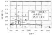
- Fig. 1is a graph showing the relationship between the year of manufacture of bridge steel and the sulfur (S) content (Ryoichi Sugano, "Steel Structure and Development of Steel Structures Supporting It and Future Prospects", 22nd and 226th Nishiyama Memorial Technical Lecture, (2016), 49.), Many of the bridge steel materials in the 1960s and 1980s related to the above-mentioned aging problem contain 0.02% (200 ppm) or more of sulfur (S). are doing. That is, the method for surface modification of steel materials of the present invention can be suitably used for steel materials of aged infrastructure.
- the friction stir welding processis not particularly limited as long as the effect of the present invention is not impaired, and the friction stir welding process can be performed by various conventionally known methods.
- the friction stir welding processutilizes friction stir welding (FSW: Friction Stir Welding), which is a solid phase bonding technology for metal materials, as a surface modification technology for metal materials.
- FSWFriction Stir Welding
- the method for surface modification of steel materials of the present inventionit is preferable to perform a friction stir welding process on a region where cracks and / or corrosion holes are present.
- material flow of the steel materialoccurs in the modified region, and the material flow can remove cracks and corrosion holes.
- cracks having a width of about 1 mmare removed by the material flow in the friction stir welding process, cracks and corroded holes generally existing in the repair target region of the steel structure can be easily removed.
- the method for modifying the surface of a steel material of the present inventionit is preferable to perform a friction stir welding process on the melt-welded portion of the steel material.
- Various steel materialsare used for large welded structures such as ships, marine structures and bridges, and the fatigue strength of the base metal is improved by increasing the tension of the steel materials, but the reliability of the welded structure as a whole is improved.
- -Safetyis rate-determined by the characteristics of the melt weld, which has the lowest toughness and fatigue strength.
- the toughness of the melt-welded portionis significantly lower than that of the base metal even when cracking in the melt-welded portion can be suppressed. That is, when a melt-welded portion is present in an aged steel structure, the life of the entire steel structure can be extended extremely efficiently by performing a friction stir process on the melt-welded portion. it can.
- the plate thickness of the steel materialis 6 to 600 mm.
- a sufficient long lifecan be achieved by modifying only the vicinity of the surface of the thick steel sheets by a friction stir welding process.
- a toolfor modifying a steel material of the present invention, it is possible to obtain an effect by forming a friction stir region in the vicinity of the surface of a thick steel sheet, so that the treatment can be easily performed.
- the depth of the friction stir welding region formed on the surface of the steel materialis not particularly limited and may be appropriately determined depending on the shape, size, material and the like of the steel structure, but is preferably 0.2 to 6 mm, for example. It is more preferably 0.5 to 3 mm, and most preferably 1 to 2 mm. By setting the thickness of the friction stir region within these ranges, it is possible to achieve both the life of the tool and the modification effect of forming the friction stir region.
- the steel materialis a rolled steel material for general structure, a rolled steel material for welded structure, a weather-resistant hot rolled steel material for welded structure, a rolled steel material for building structure, and a general structure. It is preferably any of carbon steel pipes, carbon steel pipes for building structures, and square steel pipes for general structures. When these steel materials are used as bridges and building steel frames, a friction stir region can be formed relatively easily by a friction stir process.
- the processing temperature of the friction stir welding processis A 3 points or less or A cm points or less determined by the chemical composition of the steel material.
- the base metal crystal grains of a part of the friction stir regionbecome fine equiaxed grains (such as martensite).
- the toughnesscan be improved more effectively without becoming a brittle metamorphic structure).
- embrittlement caused by sulfur (S)can be reduced.
- the treatment temperature of the friction stir welding processis set to A 1 transformation point or less determined by the chemical composition of the steel material.
- the base material crystal grains in the friction stir regionbecome fine equiaxed grains (not a brittle transformation structure such as martensite).
- the toughnesscan be improved more effectively.
- embrittlement caused by sulfur (S)can be reduced more effectively.
- the processing temperature of the friction stir welding processcan be controlled by the material, shape, rotation speed, moving speed, load, etc. of the rotating tool to be inserted into the area to be processed.
- various external cooling meansmay be used if necessary.
- the present inventionA steel structure containing at least a part of steel material,
- the sulfur (S) content of the steel materialis 200 ppm or more, and the content is 200 ppm or more.
- the existence of a friction stir region in the steel materialAlso provided are steel structures, characterized by.
- a friction stir regionexists on the surface of the steel material, and the hardness, strength, toughness, etc. of the steel material are adjusted by the friction stir region, and the life of the steel structure can be extended. Has been done. Further, it is preferable that the friction stir welding region contains equiaxed recrystallized grains. The presence of equiaxed recrystallized grains in the friction stir region can improve the toughness of the steel material.
- the friction stirring regionis not limited to those intended for surface modification, and may be a friction stirring region formed by friction stir welding.
- the sulfur (S) contentis 300 ppm or more.
- Many of the bridge steel materials in the 1960s to 1980s related to the aging problemcontain sulfur (S) of 200 ppm or more, and some of them contain sulfur (S) of 300 ppm.
- the sulfur (S) contentis 300 ppm or more, the life is extended due to the presence of the friction stir welding region.
- the plate thickness of the steel materialis 6 to 600 mm.
- the life of the thick steel sheetsis sufficiently extended by modifying only the vicinity of the surface of the thick steel sheets by the friction stir welding process.
- the depth of the friction stir welding region formed on the surface of the steel materialis not particularly limited and may be appropriately determined depending on the shape, size, material and the like of the steel structure, but is preferably 0.2 to 6 mm, for example. It is more preferably 0.5 to 3 mm, and most preferably 1 to 2 mm. By setting the thickness of the friction stir welding region within these ranges, an inexpensive and long-life steel structure can be obtained.
- the steel materialis a rolled steel material for general structure, a rolled steel material for welded structure, a weather-resistant hot rolled steel material for welded structure, a rolled steel material for building structure, and a carbon steel pipe for general structure.
- Carbon steel pipe for building structure and square steel pipe for general structureare preferable.
- the location of the friction stir welding regionis not particularly limited as long as the effect of the present invention is not impaired, and it may be formed in a region where strength and reliability are desired to be improved as a steel structure. For example, when there are cracks or corrosion holes or when there is a melt welded portion, the life of the steel structure as a whole can be extended by forming a friction stir region in the region.
- an effective and simple surface modification method for extending the life of a steel structure made of a steel material having a high sulfur (S) contentand the surface modification method have extended the life.
- Steel structurescan be provided.
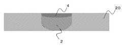
- FIG. 2is a schematic view of the method for surface modification of steel material of the present invention. Note that FIG. 2 shows a case where the friction stir welding process is applied to the melt welded portion, and the friction stir region 4 is formed on the surface of the melt welded portion 2 by using the friction stir welding process.
- the sulfur (S) content of the steel material 6is 200 ppm or more, which is the greatest feature of the surface modification method for the steel material of the present invention, and the content is preferably 300 ppm or more. ..
- Sulfur (S)is basically a harmful component for steel material 6, and the sulfur (S) content in steel material 6 is reduced as much as possible. That is, the sulfur (S) content of the steel material 6 currently produced is less than 200 ppm unless it is intentionally mixed. On the other hand, in steel materials 6 manufactured before the 1980s, when the steelmaking technology did not reach the current level, the sulfur (S) content is often 200 ppm or more or 300 ppm or more.
- the method for measuring the sulfur (S) content of the steel material 6is not particularly limited as long as the effect of the present invention is not impaired, and various conventionally known measuring methods can be used.
- the measurement methodfor example, spark discharge emission spectroscopic analysis (cantback) or wavelength dispersive fluorescent X-ray analysis is preferably used, but a handy type energy dispersive fluorescent X-ray analysis is simply used. May be good.
- the plate thickness of the steel material 6is preferably 6 to 600 mm. Where thick steel sheets are used for various infrastructure structures, a sufficient long life can be achieved by modifying only the vicinity of the surface of the thick steel sheets by a friction stir welding process.
- the depth of the friction stir welding region 4 formed on the surface of the steel material 6is not particularly limited and may be appropriately determined depending on the shape, size, material and the like of the steel structure, but may be 0.2 to 6 mm, for example. It is preferably 0.5 to 3 mm, more preferably 1 to 2 mm, and most preferably 1 to 2 mm. By setting the thickness of the friction stir region 4 in these ranges, it is possible to achieve both the life of the tool and the modification effect of the formation of the friction stir region 4.
- the steel material 6includes rolled steel for general structure, rolled steel for welded structure, weather-resistant hot rolled steel for welded structure, rolled steel for building structure, carbon steel pipe for general structure, carbon steel pipe for building structure and general. It is preferably one of the structural square steel pipes. When these steel materials are used as bridges and building steel frames, the friction stir region 4 can be formed relatively easily by a friction stir process.
- Friction stir weldingis an application of friction stir welding to the surface modification of metal materials, and is basically the same technology as friction stir welding except that the shape of the tool used may differ. Specifically, a method of obtaining a friction stir region 4 by inserting a protrusion (probe portion) provided at the tip of a rotary tool into a material to be treated (steel material 6) and moving the rotary tool while rotating it. Is.
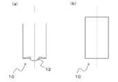
- FIG. 3is a schematic front view showing an example of a friction stir welding tool used in the surface modification method for steel materials of the present invention.
- the bottom surface of the friction stir welding tool 10preferably has a probe 12 having a length of 3 mm or less, and more preferably a probe 12 having a length of 2 mm or less (FIG. 3a). It is also possible to use a flat tool (FIG. 3b) having a substantially flat bottom surface without the probe 12. Furthermore, a tool that does not have the probe 12 and has a convex bottom surface of the friction stir welding tool 10 can also be used.
- the tool lifecan be improved and the processing cost of the friction stir welding process can be reduced.
- the friction stir welding region 4can be formed deeper than in the case of a flat surface.
- the friction stir tool 10 having the probe 12When the friction stir tool 10 having the probe 12 is press-fitted into the steel material 6 having a high melting point and high temperature deformation resistance and moved, it often breaks from the root of the probe 12 and the life of the friction stir tool 10 is reached. .. On the other hand, by using the friction stir tool 10 having a substantially flat bottom surface or a spherical crown shape, it is not necessary to consider the tool life due to the breakage of the probe 12, and the friction stir tool 10 having the probe 12 having a length of 2 mm or less is used. By using, the breakage of the probe 12 can be suppressed.
- the shape of the probe 12is not particularly limited, and a simple columnar shape or a tapered shape having a thick root and a thin tip can be used.
- the probe 12may be threaded, chamfered, or the like, but it is preferable not to perform such processing from the viewpoint of tool life.
- the friction stir welding tool 10is basically cylindrical, so that a difficult-to-sinter material or a difficult-to-process material can be used.
- the friction stir welding tool 10 that can be used in the present inventionalso includes a tool having a concave bottom surface.
- the material of the friction stirring tool 10is, for example, a tool steel such as SKD61 steel specified in JIS, a cemented carbide made of tungsten carbide (WC), cobalt (Co), nickel (Ni), and cobalt (Co).
- a based alloyscan be made of tungsten (W) alloy, iridium (Ir) refractory metals and alloys thereof such as or Si 3 N 4, PCBN like ceramics.
- the material 6 to be weldedis a steel material such as high-strength steel, it has a high melting point such as tungsten carbide (WC), a cemented carbide made of cobalt (Co), a cobalt (Co) -based alloy, and iridium (Ir). metals and their alloys, or Si 3 N 4, it is preferable to use one made if ceramics such as PCBN.
- the structure of the friction stir region 4 obtained by the friction stir treatmentis finer and more homogenized as compared with the melt welded portion 2 having the quench solidification structure and the base material of the steel material 6. Further, the toughness of the melt welded portion 2 is significantly lower than that of the base metal, but as a result of intensive research by the inventor, a friction stir region having excellent mechanical properties on the surface of the melt welded portion 2 It was clarified that the reliability of the entire steel structure can be ensured by forming No. 4.
- the processing temperature of the friction stir welding processis preferably A 3 points or less or A cm points or less, which is determined by the chemical composition of the steel material 6.
- a 3 point or less or A cm point or less of the steel material 6By setting the treatment temperature of at least a part of the friction stir region 4 to A 3 point or less or A cm point or less of the steel material 6, a part of the base metal crystal grains of the friction stir region 4 becomes fine equiaxed grains (martensite). It does not become a brittle transformation structure such as), and the toughness can be improved more effectively.
- embrittlement caused by sulfur (S)can be reduced.
- the toughness of the friction stir welding region 4can be evaluated by measuring the impact absorption energy by, for example, a micro impact test using a micro test piece cut out from the region. More specifically, the absorbed energy can be calculated by forming a notch at a place where the shock absorption energy is to be measured and integrating the load displacement curve when the shock is applied to the place.
- the impact absorption energy of the friction stir welding region 4is 80% or more of the impact absorption energy of the steel material 6, high reliability can be imparted to the steel structure, for example, a bridge, an offshore structure, or the like. It can be suitably used as a structure that requires high reliability for a long period of time.
- the impact absorption energy of the friction stir region 4is preferably 90% or more, more preferably 95% or more, and most preferably 100% or more of the impact absorption energy of the steel material 6.
- the processing temperature of the friction stir welding processis equal to or lower than the A 1 transformation point determined by the chemical composition of the steel material 6.
- the base metal crystal grains of the friction stir region 4become fine equiaxed grains (if it is a brittle transformation structure such as martensite).
- the toughnesscan be improved more effectively.
- embrittlement caused by sulfur (S)can be reduced more effectively.
- the processing temperature of the friction stir welding processcan be controlled by the material, shape, rotation speed, moving speed, load, etc. of the friction stir tool 10 to be inserted into the area to be processed.
- various external cooling meansmay be used if necessary.
- the friction stir welding process in the present inventionincludes (1) a mode in which the friction stir tool 10 is rotated and moved in the processing direction, and (2) a mode in which the friction stir tool 10 is rotated and not moved at the processing position. 3)
- the mode of superimposing the processing regions formed in (1), the mode of superimposing the processing regions formed in (4) and (2), and the processes of (5) (1) to (4)are arbitrarily combined. Aspects, are included.
- the steel structure of the present inventionprovides a steel structure having a friction stir region 4 formed by the method of surface modification of the steel material of the present invention.
- the region that determines the mechanical properties of the entire steel structureis modified in the friction stir welding region 4, so that the mechanical properties of the steel material 6 are sufficiently improved. It is possible to obtain a steel structure that can be expressed in.
- FIG. 4shows a schematic cross-sectional view of the vicinity of the friction stir region in the case where the friction stir region is formed in the melt welded portion of the steel structure of the present invention.
- the sulfur (S) content of the steel material 6is preferably 200 ppm or more, and the content is preferably 300 ppm or more.
- the friction stir region 4contains equiaxed recrystallized grains. The presence of equiaxed recrystallized grains (ferrite recrystallized grains) in the friction stir welding region 4 can improve the toughness of the steel material 6.
- the plate thickness of the steel material 6is preferably 6 to 600 mm. Where thick steel sheets are used for various infrastructure structures, the life of the thick steel sheets is sufficiently extended by modifying only the vicinity of the surface of the thick steel sheets by the friction stir welding process.
- the depth of the friction stir welding region 4 formed on the surface of the steel material 6is not particularly limited and may be appropriately determined depending on the shape, size, material and the like of the steel structure, but may be 0.2 to 6 mm, for example. It is preferably 0.5 to 3 mm, more preferably 1 to 2 mm, and most preferably 1 to 2 mm. By setting the thickness of the friction stir welding region 4 in these ranges, an inexpensive and long-life steel structure can be obtained.
- the steel material 6includes rolled steel for general structure, rolled steel for welded structure, weather-resistant hot rolled steel for welded structure, rolled steel for building structure, carbon steel pipe for general structure, carbon steel pipe for building structure and general. It is preferably one of the structural square steel pipes. By using these steel materials, steel structures can be made into various infrastructure structures.
- the location of the friction stir welding region 4is not particularly limited as long as the effect of the present invention is not impaired, and it may be formed in a region where strength and reliability are desired to be improved as a steel structure. For example, when there are cracks or corrosion holes or when there is a melt welded portion, the life of the steel structure as a whole can be extended by forming the friction stir welding region 4 in the region.
- the region where cracks and corrosion holes exist and all the regions of the melt welded portionare modified, but friction stir is performed in the region that controls the mechanical properties of the steel structure. It is preferable that the region 4 is formed.
- Example 10.03 mass% S steel plate >> A steel ingot having a target composition of the values shown in Table 1 was prepared by vacuum induction melting, and a steel plate of 90 mm (thickness) ⁇ 145 mm (width) ⁇ 380 mm (length) was obtained by hot rolling at 950 ° C. .. Then, after sawing to make 90 mm (thickness) ⁇ 145 mm (width) ⁇ 180 mm (length), hot rolling at 950 ° C. made the plate thickness 4.5 mm. The values shown in Table 1 are mass%.
- test steel sheet 1having a size of 4.5 mm (thickness) ⁇ 100 mm (width) ⁇ 200 mm (length).
- Table 2shows the composition of the test steel sheet 1 measured by spark discharge emission spectroscopic analysis (Kantback) in mass%.
- the content of sulfur (S)is 0.027% by mass.
- a cemented carbide tool(the probe does not have a screw) having a shape of a shoulder diameter of 15 mm, a probe diameter of 6 mm, and a probe length of 2.9 mm is used for the steel plate 1 under test, and the tool rotation speed: 400 rpm, the joining speed.
- Friction stir welding processis performed under the conditions of: 150 mm / min, joining load: 2.5 ton, tool advance angle: 3 °, joining atmosphere: Ar (high temperature processing condition: A 3 points or more), and friction on the surface of the test steel sheet 1. A stirring region was formed.
- a cemented carbide tool(the probe does not have a screw) having a shape of a shoulder diameter of 15 mm, a probe diameter of 6 mm, and a probe length of 2.9 mm was used for the test steel plate 1, and the tool rotation speed was 100 rpm.
- Example 20.06 mass% S steel plate>> A test steel sheet 2 was obtained in the same manner as in Example 1 except that a steel ingot having a target composition of the value of Example 2 shown in Table 1 was prepared. The actual composition of the test steel sheet 2 is as shown in Table 2, and the sulfur (S) content is 0.053% by mass. Further, in the same manner as in Example 1, a friction stir welding process was performed under high temperature treatment conditions and low temperature treatment conditions.
- Example 30.10 mass% S steel sheet>> A test steel sheet 3 was obtained in the same manner as in Example 1 except that a steel ingot having a target composition of the value of Example 3 shown in Table 1 was produced. The actual composition of the test steel sheet 3 is as shown in Table 2, and the sulfur (S) content is 0.100% by mass. Further, in the same manner as in Example 1, a friction stir welding process was performed under high temperature treatment conditions and low temperature treatment conditions.
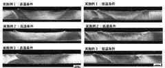
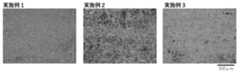
- FIG. 5shows an external photograph (surface photograph) of the friction stir welding region formed in Examples 1 to 3. It can be seen that no cracks or the like are generated in or near all the friction stir regions, and a good friction stir region is obtained. The results show that even when the sulfur (S) content of the steel material is high, surface modification and friction stir welding by the friction stir process are possible.
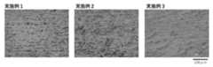
- FIG. 6shows a cross-sectional macro photograph of the friction stir welding region formed in Examples 1 to 3. Even in the cross section, no cracks or the like were generated in or near all the friction stir regions, and even when the sulfur (S) content of the steel material was high, a good friction stir region was obtained. I understand.
- FIG. 7shows the structural photographs of the test steel sheets 1 to 3 and FIG. 7 shows the structure photographs of the friction stir welding regions formed on the test steel sheets 1 to 3 under high temperature treatment conditions.
- FIG. 9shows a microstructure photograph of the friction stir welding region formed on the test steel sheet 3 under low temperature treatment conditions. All of them have a structure basically composed of ferrite-pearlite, but it can be seen that the structure of the friction stir region is finer than that of the test steel material. Further, in the friction stir region formed under high temperature conditions, segregation of sulfur is suppressed (particularly, the test steel plate 1 and the test steel plate 3 in FIG. 8), and when it is desired to suppress the segregation of sulfur.
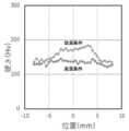
- the results of the test steel sheets 1 to 3are shown in FIGS. 10 to 12, respectively, with respect to the hardness distribution of the friction stir welding region formed under the high temperature treatment condition and the low temperature treatment condition.
- the hardness of the friction stir region obtained under high temperature conditionsis about the same as that of the base material, and the hardness of the friction stir region obtained under low temperature conditions is higher than that of the base material.
- the resultshows that the hardness of the friction stir region can be controlled by the friction stir process conditions, and the friction stir process conditions may be determined according to desired characteristics (hardness, strength, toughness, etc.). Since the friction stir welding region formed under the low temperature treatment condition contains equiaxed grains, it can be suitably used for surface modification (extending the life) of the steel material constituting the aged infrastructure.
- the hardness of the friction stir region obtained under low temperature conditionsincreases as the sulfur content increases, and if a higher surface hardness is required, a friction stir process is performed on steel materials with a high sulfur content. It is preferable to apply.
Landscapes
- Chemical & Material Sciences (AREA)
- Engineering & Computer Science (AREA)
- Mechanical Engineering (AREA)
- Materials Engineering (AREA)
- Metallurgy (AREA)
- Organic Chemistry (AREA)
- Physics & Mathematics (AREA)
- Thermal Sciences (AREA)
- Crystallography & Structural Chemistry (AREA)
- Pressure Welding/Diffusion-Bonding (AREA)
Abstract
Description
Translated fromJapanese本発明は硫黄の含有量が多い鉄鋼材の表面改質方法及び当該表面改質が施された鉄鋼構造物に関する。The present invention relates to a method for surface modification of a steel material having a high sulfur content and a steel structure to which the surface modification has been performed.
鉄鋼材に含まれる硫黄は基本的に有害な成分であり、硫黄の含有量が多い場合は溶接等に伴う溶融凝固時に高温割れが発生してしまう。これに対して、近年では製鋼技術の高度化により硫黄の含有量は極力低減されているが、当該含有量が十分に低減されていない不良品も存在する。このような鉄鋼材に関しては、溶融溶接を用いた継手の作製や溶融凝固を伴う補修作業等を行うことが極めて困難である。Sulfur contained in steel materials is basically a harmful component, and if the sulfur content is high, high-temperature cracking will occur during melt solidification due to welding and the like. On the other hand, in recent years, the sulfur content has been reduced as much as possible due to the sophistication of steelmaking technology, but there are some defective products whose content has not been sufficiently reduced. With respect to such steel materials, it is extremely difficult to manufacture joints using melt welding and repair work accompanied by melt solidification.
また、国内のインフラ(橋梁や高速道路等の一般インフラ及びプラント等の産業インフラ)の多くは高度経済成長期に整備されており、その老朽化の影響は今後加速的に深刻さを増すことが予想されている。In addition, most of the domestic infrastructure (general infrastructure such as bridges and highways and industrial infrastructure such as plants) was developed during the period of high economic growth, and the impact of its aging may accelerate in the future. It is expected.
具体的には、岡山県の道路建設課が「道路橋梁の長寿命化」としてウェブサイト(http://www.pref.okayama.jp/page/detail-66940.html)に掲載している内容においては、「岡山県が管理する道路橋梁は、橋長15m以上が995橋、橋長15m未満が2,090橋の計3,085橋(平成27年3月時点)あります。これらの橋梁は、高度経済成長期に建設されたものが多く、50年経過橋梁数は、現在の514橋(20%)から20年後には1852橋(74%)となり、急速に高齢化が進行する見込みです。」とされている。Specifically, the contents posted on the website (http://www.pref.okayama.jp/page/dateil-66940.html) as "extending the life of road bridges" by the Road Construction Division of Okayama Prefecture. In "The road bridges managed by Okayama Prefecture are 995 bridges with a bridge length of 15 m or more and 2,090 bridges with a bridge length of less than 15 m, for a total of 3,085 bridges (as of March 2015). Many of the bridges were built during the period of high economic growth, and the number of bridges after 50 years will increase from 514 (20%) at present to 1852 (74%) in 20 years, and the aging of the bridge is expected to progress rapidly. . ".
このような状況下において、当該インフラの老朽化問題に適切に対処していくためには、老朽化したインフラを低コストで長寿命化できる補修技術を早急に確立する必要がある。ここで、鉄鋼構造物の補修には溶融溶接が効果的であるが、高度経済成長期に使用された鉄鋼材には硫黄(S)が多く含まれていることが多い。Under such circumstances, in order to appropriately deal with the problem of aging infrastructure, it is necessary to urgently establish repair technology that can extend the life of aging infrastructure at low cost. Here, although melt welding is effective for repairing steel structures, the steel materials used during the period of high economic growth often contain a large amount of sulfur (S).
硫黄(S)を多く含む鉄鋼材は、溶接時に接合部の最終凝固域で低融点化合物が母材結晶粒界に残留し、凝固収縮時のひずみにより粒界が開口して高温割れが発生しやすいことが知られている。即ち、老朽化したインフラの長寿命化のために溶融溶接を用いることは極めて困難である。In steel materials containing a large amount of sulfur (S), low melting point compounds remain at the grain boundaries of the base metal in the final solidification region of the joint during welding, and the grain boundaries open due to strain during solidification shrinkage, causing high-temperature cracking. It is known to be easy. That is, it is extremely difficult to use hot-dip welding to extend the life of aging infrastructure.
これに対し、特許文献1(特開2008-246501号公報)では、ニッケル基合金またはオーステナイト系ステンレス鋼製の溶接材からなる溶接部で部材を接合して構成された溶接構造物において、溶接部の表面、又は溶接部と溶接部近傍の部材との表面に、回転するツールを表面垂直方向の荷重負荷により圧着させた状態で移動させて摩擦攪拌処理を行い、摩擦攪拌処理を行った摩擦攪拌処理部の柱状晶方向を表面面内方向とすることを特徴とする溶接構造物の応力腐食割れ進展性の改善方法が提案されている。On the other hand, in Patent Document 1 (Japanese Unexamined Patent Publication No. 2008-246501), in a welded structure formed by joining members with a welded material made of a nickel-based alloy or an austenite-based stainless steel, the welded portion is formed. Friction stir welding was performed by moving a rotating tool on the surface of the welded portion or the surface of the welded portion and the member in the vicinity of the welded portion in a state of being crimped by a load load in the direction perpendicular to the surface. A method for improving the proneness of stress corrosion cracking of a welded structure, which is characterized in that the columnar crystal direction of the treated portion is in the surface in-plane direction, has been proposed.
前記特許文献1に記載の溶接構造物の応力腐食割れ進展性の改善方法においては、摩擦攪拌処理部の柱状晶方向を表面面内方向とすることにより、溶接部での応力腐食割れの発生を抑制し、また、溶接部に応力腐食割れが発生しても、深さ方向のき裂進展は、柱状晶方向が応力腐食割れ方向と垂直になっているので、応力腐食割れのき裂進展速度を応力腐食割れが柱状晶方向に沿って発生する場合と比べ1/10程度に減速させることが可能となる。これにより、溶接部の耐用年数を長くすることができ、溶接構造物の寿命を長くすることができるとしている。In the method for improving the progress of stress corrosion cracking of a welded structure described in Patent Document 1, the occurrence of stress corrosion cracking in the welded portion is caused by setting the columnar crystal direction of the friction stirring processing portion to the in-surface direction. Even if stress corrosion cracking occurs in the weld, the crack growth in the depth direction is such that the columnar crystal direction is perpendicular to the stress corrosion cracking direction, so the crack growth rate of the stress corrosion cracking is suppressed. It is possible to reduce the stress corrosion cracking to about 1/10 as compared with the case where stress corrosion cracking occurs along the columnar crystal direction. As a result, the service life of the welded portion can be extended, and the life of the welded structure can be extended.
しかしながら、上記特許文献1に開示されている溶接構造物の応力腐食割れ進展性の改善方法は、溶接部の柱状晶方向を表面面内方向とすることを特徴としており、効果を奏する対象材がニッケル基合金及びオーステナイト系ステンレス鋼製の溶接材からなる溶接部に限定されている。加えて、腐食環境下にない場合の疲労強度に関する効果については記載されておらず、硫黄(S)含有量が多い鉄鋼材に対する効果については全く開示されていない。However, the method for improving the stress corrosion cracking progression of a welded structure disclosed in Patent Document 1 is characterized in that the columnar crystal direction of the welded portion is the in-plane direction of the surface surface, and the target material that exerts the effect is It is limited to welds made of nickel-based alloy and austenitic stainless steel welds. In addition, the effect on fatigue strength when not in a corrosive environment is not described, and the effect on steel materials with a high sulfur (S) content is not disclosed at all.
以上のような従来技術における問題点に鑑み、本発明の目的は、硫黄(S)含有量が多い鉄鋼材からなる鉄鋼構造物を長寿命化するための効果的かつ簡便な表面改質方法、及び当該表面改質方法によって長寿命化された鉄鋼構造物を提供することにある。In view of the above problems in the prior art, an object of the present invention is an effective and simple surface modification method for extending the life of a steel structure made of a steel material having a high sulfur (S) content. The present invention is to provide a steel structure having a long life by the surface modification method.
本発明者は上記目的を達成すべく、鉄鋼材の硫黄(S)含有量と摩擦攪拌プロセスによって得られる作用効果の関係について鋭意研究を重ねた結果、硫黄(S)含有量が一定値以上となる鉄鋼材に関しては、溶融溶接よりも摩擦攪拌プロセスを用いた補修(表面改質)がより効果的であること等を見出し、本発明に到達した。As a result of intensive research on the relationship between the sulfur (S) content of steel materials and the action and effect obtained by the friction stir welding process, the present inventor has determined that the sulfur (S) content is above a certain value. The present invention has been reached by finding that repair (surface modification) using a friction stir welding process is more effective than hot-dip welding.
即ち、本発明は、
摩擦攪拌プロセスを用いて鉄鋼材の表面に摩擦攪拌領域を形成させる表面改質方法であって、
前記鉄鋼材の硫黄(S)の含有量が200ppm以上であること、
を特徴とする鉄鋼材の表面改質方法、を提供する。That is, the present invention
A surface modification method in which a friction stir region is formed on the surface of a steel material using a friction stir process.
The sulfur (S) content of the steel material is 200 ppm or more.
Provided is a method for surface modification of a steel material, which is characterized by the above.
本発明の鉄鋼材の表面改質方法においては、前記硫黄(S)の含有量が300ppm以上であること、が好ましい。鉄鋼材の硫黄(S)の含有量が200ppm以上となる場合は溶融溶接中に割れが誘発されることが多く、当該含有量が300ppm以上となると、殆どの場合で割れが発生する。これに対し、鉄鋼材を溶融させない固相プロセスである摩擦攪拌プロセスを用いることで、硫黄(S)を200ppm以上含有する鉄鋼材であっても良好な改質領域(摩擦攪拌領域)を得ることができ、当該含有量が300ppm以上であっても同様に良好な改質領域(摩擦攪拌領域)を得ることができる。In the method for surface modification of steel materials of the present invention, it is preferable that the sulfur (S) content is 300 ppm or more. When the sulfur (S) content of the steel material is 200 ppm or more, cracks are often induced during melt welding, and when the content is 300 ppm or more, cracks occur in most cases. On the other hand, by using a friction stir welding process, which is a solid phase process that does not melt the steel material, a good modified region (friction stirring region) can be obtained even for a steel material containing 200 ppm or more of sulfur (S). Even if the content is 300 ppm or more, a similarly good modified region (friction stir welding region) can be obtained.
図1は橋梁鋼材の製造年と硫黄(S)含有量の関係を示すグラフであるが(菅野良一、”鋼構造とそれを支える鋼材の発展と今後の展望”、第225・226回西山記念技術講座、(2016)、49.)、上述の老朽化問題に関係する1960~1980年代の橋梁鋼材には、0.02%(200ppm)以上の硫黄(S)を含んでいるものが多く存在している。即ち、本発明の鉄鋼材の表面改質方法は、老朽化したインフラの鉄鋼材に対して好適に用いることができる。Fig. 1 is a graph showing the relationship between the year of manufacture of bridge steel and the sulfur (S) content (Ryoichi Sugano, "Steel Structure and Development of Steel Structures Supporting It and Future Prospects", 22nd and 226th Nishiyama Memorial Technical Lecture, (2016), 49.), Many of the bridge steel materials in the 1960s and 1980s related to the above-mentioned aging problem contain 0.02% (200 ppm) or more of sulfur (S). are doing. That is, the method for surface modification of steel materials of the present invention can be suitably used for steel materials of aged infrastructure.
摩擦攪拌プロセスは、本発明の効果を損なわない限りにおいて特に限定されず、従来公知の種々の方法で摩擦攪拌プロセスを施すことができる。なお、摩擦攪拌プロセスとは、金属材の固相接合技術である摩擦攪拌接合(FSW:Friction Stir Welding)を金属材の表面改質技術として利用するものである。The friction stir welding process is not particularly limited as long as the effect of the present invention is not impaired, and the friction stir welding process can be performed by various conventionally known methods. The friction stir welding process utilizes friction stir welding (FSW: Friction Stir Welding), which is a solid phase bonding technology for metal materials, as a surface modification technology for metal materials.
また、本発明の鉄鋼材の表面改質方法では、亀裂及び/又は腐食孔が存在する領域に摩擦攪拌プロセスを施すこと、が好ましい。摩擦攪拌プロセスにおいては改質領域において鉄鋼材の材料流動が生じ、当該材料流動によって亀裂や腐食孔を除去することができる。ここで、摩擦攪拌プロセスの材料流動で1mm幅程度の亀裂は除去されることから、鉄鋼構造物の補修対象領域に一般的に存在する亀裂や腐食孔は容易に除去することができる。Further, in the method for surface modification of steel materials of the present invention, it is preferable to perform a friction stir welding process on a region where cracks and / or corrosion holes are present. In the friction stir welding process, material flow of the steel material occurs in the modified region, and the material flow can remove cracks and corrosion holes. Here, since cracks having a width of about 1 mm are removed by the material flow in the friction stir welding process, cracks and corroded holes generally existing in the repair target region of the steel structure can be easily removed.
また、本発明の鉄鋼材の表面改質方法では、前記鉄鋼材の溶融溶接部に摩擦攪拌プロセスを施すこと、が好ましい。船舶、海洋構造物及び橋梁等の大型溶接構造物には様々な鉄鋼材が利用されており、鉄鋼材の高張力化によって母材の疲労強度は向上するが、溶接構造物全体としての信頼性・安全性は、最も靭性や疲労強度が低い溶融溶接部の特性によって律速されてしまう。特に、硫黄(S)を多く含有する鉄鋼材においては、溶融溶接部における割れを抑制できた場合であっても、当該溶融溶接部の靭性は母材よりも大きく低下する。即ち、老朽化が進んだ鉄鋼構造物に溶融溶接部が存在する場合、当該溶融溶接部に対して摩擦攪拌プロセスを施すことによって、極めて効率的に鉄鋼構造物全体の長寿命化を図ることができる。Further, in the method for modifying the surface of a steel material of the present invention, it is preferable to perform a friction stir welding process on the melt-welded portion of the steel material. Various steel materials are used for large welded structures such as ships, marine structures and bridges, and the fatigue strength of the base metal is improved by increasing the tension of the steel materials, but the reliability of the welded structure as a whole is improved. -Safety is rate-determined by the characteristics of the melt weld, which has the lowest toughness and fatigue strength. In particular, in a steel material containing a large amount of sulfur (S), the toughness of the melt-welded portion is significantly lower than that of the base metal even when cracking in the melt-welded portion can be suppressed. That is, when a melt-welded portion is present in an aged steel structure, the life of the entire steel structure can be extended extremely efficiently by performing a friction stir process on the melt-welded portion. it can.
また、本発明の鉄鋼材の表面改質方法では、前記鉄鋼材の板厚が6~600mmであること、が好ましい。各種インフラ構造物には厚鋼板が使用されるところ、摩擦攪拌プロセスによって厚鋼板の表面近傍のみを改質することによって、十分な長寿命化を図ることができる。ここで、深い摩擦攪拌領域を形成するためには当該深さに応じた突起部(プローブ部)を有するツール(摩擦攪拌用工具)を用いる必要があるが、プローブ部が長い場合は摩擦攪拌プロセス中にツール破断が生じ易い。これに対し、本発明の鉄鋼材の改質方法では、厚鋼板に対しても表面近傍における摩擦攪拌領域の形成で効果を得ることができることから、容易に処理を施すことができる。Further, in the method for modifying the surface of a steel material of the present invention, it is preferable that the plate thickness of the steel material is 6 to 600 mm. Where thick steel sheets are used for various infrastructure structures, a sufficient long life can be achieved by modifying only the vicinity of the surface of the thick steel sheets by a friction stir welding process. Here, in order to form a deep friction stir region, it is necessary to use a tool (friction stirring tool) having a protrusion (probe portion) corresponding to the depth, but if the probe portion is long, the friction stirring process Tool breakage is likely to occur inside. On the other hand, in the method for modifying a steel material of the present invention, it is possible to obtain an effect by forming a friction stir region in the vicinity of the surface of a thick steel sheet, so that the treatment can be easily performed.
鉄鋼材の表面に形成させる摩擦攪拌領域の深さは特に限定されず、鉄鋼構造物の形状、サイズ及び材質等によって適宜決定すればよいが、例えば、0.2~6mmとすることが好ましく、0.5~3mmとすることがより好ましく、1~2mmとすることが最も好ましい。摩擦攪拌領域の厚さをこれらの範囲とすることで、ツールの寿命と摩擦攪拌領域の形成による改質効果を両立することができる。The depth of the friction stir welding region formed on the surface of the steel material is not particularly limited and may be appropriately determined depending on the shape, size, material and the like of the steel structure, but is preferably 0.2 to 6 mm, for example. It is more preferably 0.5 to 3 mm, and most preferably 1 to 2 mm. By setting the thickness of the friction stir region within these ranges, it is possible to achieve both the life of the tool and the modification effect of forming the friction stir region.
また、本発明の鉄鋼材の表面改質方法では、前記鉄鋼材が、一般構造用圧延鋼材、溶接構造用圧延鋼材、溶接構造用耐候性熱間圧延鋼材、建築構造用圧延鋼材、一般構造用炭素鋼鋼管、建築構造用炭素鋼鋼管及び一般構造用角形鋼管のうちのいずれかであること、が好ましい。これらの鉄鋼材は橋梁や建築鉄骨として用いられるところ、摩擦攪拌プロセスによって比較的容易に摩擦攪拌領域を形成することができる。Further, in the method for surface modification of a steel material of the present invention, the steel material is a rolled steel material for general structure, a rolled steel material for welded structure, a weather-resistant hot rolled steel material for welded structure, a rolled steel material for building structure, and a general structure. It is preferably any of carbon steel pipes, carbon steel pipes for building structures, and square steel pipes for general structures. When these steel materials are used as bridges and building steel frames, a friction stir region can be formed relatively easily by a friction stir process.
また、本発明の鉄鋼材の表面改質方法では、前記摩擦攪拌プロセスの処理温度を前記鉄鋼材の化学組成で決定されるA3点以下又はAcm点以下とすること、が好ましい。摩擦攪拌領域の少なくとも一部の処理温度を鉄鋼材のA3点以下又はAcm点以下とすることで、当該摩擦攪拌領域の一部分の母材結晶粒が微細等軸粒となり(マルテンサイト等の脆い変態組織とならず)、より効果的に靭性を向上させることができる。また、硫黄(S)に起因する脆化を低減することができる。Further, in the method for modifying the surface of a steel material of the present invention, it is preferable that the processing temperature of the friction stir welding process is A3 points or less or Acm points or less determined by the chemical composition of the steel material. By setting the treatment temperature of at least a part of the friction stir region to A3 point or less or Acm point or less of the steel material, the base metal crystal grains of a part of the friction stir region become fine equiaxed grains (such as martensite). The toughness can be improved more effectively without becoming a brittle metamorphic structure). In addition, embrittlement caused by sulfur (S) can be reduced.
更に、本発明の鉄鋼材の表面改質方法では、前記摩擦攪拌プロセスの処理温度を前記鉄鋼材の化学組成で決定されるA1変態点以下とすること、が好ましい。摩擦攪拌領域の少なくとも一部の処理温度を鉄鋼材のA1点以下とすることで、当該摩擦攪拌領域の母材結晶粒が微細等軸粒となり(マルテンサイト等の脆い変態組織とならず)、より効果的に靭性を向上させることができる。また、硫黄(S)に起因する脆化をより効果的に低減することができる。なお、摩擦攪拌プロセスの処理温度は、被処理領域に挿入する回転ツールの材質、形状、回転速度、移動速度及び荷重等によって制御できる。また、必要に応じて種々の外部冷却手段を用いてもよい。Further, in the method for modifying the surface of a steel material of the present invention, it is preferable that the treatment temperature of the friction stir welding process is set to A1 transformation point or less determined by the chemical composition of the steel material. By setting the treatment temperature of at least a part of the friction stir region to A1 point or less of the steel material, the base material crystal grains in the friction stir region become fine equiaxed grains (not a brittle transformation structure such as martensite). , The toughness can be improved more effectively. In addition, embrittlement caused by sulfur (S) can be reduced more effectively. The processing temperature of the friction stir welding process can be controlled by the material, shape, rotation speed, moving speed, load, etc. of the rotating tool to be inserted into the area to be processed. Moreover, various external cooling means may be used if necessary.
また、本発明は、
少なくとも一部に鉄鋼材を含む鉄鋼構造物であって、
前記鉄鋼材の硫黄(S)の含有量が200ppm以上であり、
前記鉄鋼材に摩擦攪拌領域が存在すること、
を特徴とする鉄鋼構造物、も提供する。In addition, the present invention
A steel structure containing at least a part of steel material,
The sulfur (S) content of the steel material is 200 ppm or more, and the content is 200 ppm or more.
The existence of a friction stir region in the steel material,
Also provided are steel structures, characterized by.
本発明の鉄鋼構造物においては、鉄鋼材の表面に摩擦攪拌領域が存在し、当該摩擦攪拌領域によって鉄鋼材の硬度、強度及び靭性等が調整されており、鉄鋼構造物の長寿命化が図られている。また、当該摩擦攪拌領域には等軸状の再結晶粒が含まれていることが好ましい。摩擦攪拌領域に等軸状の再結晶粒が存在することで、鉄鋼材の靭性を向上させることができる。ここで、摩擦攪拌領域は表面改質を目的としたものに限られず、摩擦攪拌接合で形成される摩擦攪拌領域であってもよい。In the steel structure of the present invention, a friction stir region exists on the surface of the steel material, and the hardness, strength, toughness, etc. of the steel material are adjusted by the friction stir region, and the life of the steel structure can be extended. Has been done. Further, it is preferable that the friction stir welding region contains equiaxed recrystallized grains. The presence of equiaxed recrystallized grains in the friction stir region can improve the toughness of the steel material. Here, the friction stirring region is not limited to those intended for surface modification, and may be a friction stirring region formed by friction stir welding.
また、本発明の鉄鋼構造物においては、硫黄(S)の含有量が300ppm以上であること、が好ましい。老朽化問題に関係する1960~1980年代の橋梁鋼材には、200ppm以上の硫黄(S)を含んでいるものが多く存在しており、300ppmの硫黄(S)を含んでいるものも存在する。本発明の鉄鋼構造物では、硫黄(S)の含有量が300ppm以上であっても、摩擦攪拌領域の存在によって長寿命化が図られている。Further, in the steel structure of the present invention, it is preferable that the sulfur (S) content is 300 ppm or more. Many of the bridge steel materials in the 1960s to 1980s related to the aging problem contain sulfur (S) of 200 ppm or more, and some of them contain sulfur (S) of 300 ppm. In the steel structure of the present invention, even if the sulfur (S) content is 300 ppm or more, the life is extended due to the presence of the friction stir welding region.
また、本発明の鉄鋼構造物においては、前記鉄鋼材の板厚が6~600mmであること、が好ましい。各種インフラ構造物には厚鋼板が使用されるところ、摩擦攪拌プロセスによって厚鋼板の表面近傍のみが改質されていることによって、十分な長寿命化が図られている。 Further, in the steel structure of the present invention, it is preferable that the plate thickness of the steel material is 6 to 600 mm. Where thick steel sheets are used for various infrastructure structures, the life of the thick steel sheets is sufficiently extended by modifying only the vicinity of the surface of the thick steel sheets by the friction stir welding process.
鉄鋼材の表面に形成させる摩擦攪拌領域の深さは特に限定されず、鉄鋼構造物の形状、サイズ及び材質等によって適宜決定すればよいが、例えば、0.2~6mmとすることが好ましく、0.5~3mmとすることがより好ましく、1~2mmとすることが最も好ましい。摩擦攪拌領域の厚さをこれらの範囲とすることで、安価かつ長寿命な鉄鋼構造物とすることができる。The depth of the friction stir welding region formed on the surface of the steel material is not particularly limited and may be appropriately determined depending on the shape, size, material and the like of the steel structure, but is preferably 0.2 to 6 mm, for example. It is more preferably 0.5 to 3 mm, and most preferably 1 to 2 mm. By setting the thickness of the friction stir welding region within these ranges, an inexpensive and long-life steel structure can be obtained.
また、本発明の鉄鋼構造物においては、前記鉄鋼材が、一般構造用圧延鋼材、溶接構造用圧延鋼材、溶接構造用耐候性熱間圧延鋼材、建築構造用圧延鋼材、一般構造用炭素鋼鋼管、建築構造用炭素鋼鋼管及び一般構造用角形鋼管のうちのいずれかであること、が好ましい。これらの鉄鋼材を用いることで、鉄鋼構造物を種々のインフラ構造物とすることができる。Further, in the steel structure of the present invention, the steel material is a rolled steel material for general structure, a rolled steel material for welded structure, a weather-resistant hot rolled steel material for welded structure, a rolled steel material for building structure, and a carbon steel pipe for general structure. , Carbon steel pipe for building structure and square steel pipe for general structure are preferable. By using these steel materials, steel structures can be made into various infrastructure structures.
本発明の効果を損なわない限りにおいて、摩擦攪拌領域の場所は特に限定されず、鉄鋼構造物として強度や信頼性を向上させたい領域に形成させればよい。例えば、亀裂や腐食孔が存在する場合や溶融溶接部が存在する場合は、当該領域に摩擦攪拌領域を形成させることで、鉄鋼構造物全体としての寿命を長くすることができる。The location of the friction stir welding region is not particularly limited as long as the effect of the present invention is not impaired, and it may be formed in a region where strength and reliability are desired to be improved as a steel structure. For example, when there are cracks or corrosion holes or when there is a melt welded portion, the life of the steel structure as a whole can be extended by forming a friction stir region in the region.
本発明によれば、硫黄(S)含有量が多い鉄鋼材からなる鉄鋼構造物を長寿命化するための効果的かつ簡便な表面改質方法、及び当該表面改質方法によって長寿命化された鉄鋼構造物を提供することができる。According to the present invention, an effective and simple surface modification method for extending the life of a steel structure made of a steel material having a high sulfur (S) content, and the surface modification method have extended the life. Steel structures can be provided.
以下、図面を参照しながら本発明の鉄鋼材の表面改質方法及び鉄鋼構造物の代表的な実施形態について詳細に説明するが、本発明はこれらのみに限定されるものではない。なお、以下の説明では、同一または相当部分には同一符号を付し、重複する説明は省略する場合がある。また、図面は、本発明を概念的に説明するためのものであるから、表された各構成要素の寸法やそれらの比は実際のものとは異なる場合もある。Hereinafter, the method for surface modification of the steel material of the present invention and typical embodiments of the steel structure will be described in detail with reference to the drawings, but the present invention is not limited to these. In the following description, the same or corresponding parts may be designated by the same reference numerals, and duplicate description may be omitted. Moreover, since the drawings are for conceptually explaining the present invention, the dimensions of each component represented and their ratios may differ from the actual ones.
(1)鉄鋼材の表面改質方法
図2は、本発明の鉄鋼材の表面改質方法の模式図である。なお、図2においては、溶融溶接部に対して摩擦攪拌プロセスを施す場合について示しており、摩擦攪拌プロセスを用いて溶融溶接部2の表面に摩擦攪拌領域4を形成させている。ここで、鉄鋼材6の硫黄(S)の含有量が200ppm以上であることが、本発明の鉄鋼材の表面改質方法の最大の特徴であり、当該含有量は300ppm以上であることが好ましい。(1) Method for surface modification of steel material FIG. 2 is a schematic view of the method for surface modification of steel material of the present invention. Note that FIG. 2 shows a case where the friction stir welding process is applied to the melt welded portion, and the
硫黄(S)は鉄鋼材6にとっては基本的に有害な成分であり、鉄鋼材6における硫黄(S)含有量は可能な限り低減されている。即ち、意図的に混入させない限り、現在製造されている鉄鋼材6の硫黄(S)含有量は200ppm未満となっている。これに対し、製鋼技術が現在のレベルに達していなかった1980年代以前に製造された鉄鋼材6では、硫黄(S)含有量が200ppm以上や300ppm以上となっている場合が多く存在する。Sulfur (S) is basically a harmful component for
ここで、鉄鋼材6の硫黄(S)含有量の測定方法は、本発明の効果を損なわない限りにおいて特に限定されず、従来公知の種々の測定方法を用いることができる。当該測定方法としては、例えば、スパーク放電発光分光分析(カントバック)や波長分散型の蛍光X線分析を用いることが好ましいが、簡易的にハンディタイプのエネルギー分散型の蛍光X線分析を用いてもよい。Here, the method for measuring the sulfur (S) content of the
また、鉄鋼材6の板厚は6~600mmであることが好ましい。各種インフラ構造物には厚鋼板が使用されるところ、摩擦攪拌プロセスによって厚鋼板の表面近傍のみを改質することによって、十分な長寿命化を図ることができる。Further, the plate thickness of the
鉄鋼材6の表面に形成させる摩擦攪拌領域4の深さは特に限定されず、鉄鋼構造物の形状、サイズ及び材質等によって適宜決定すればよいが、例えば、0.2~6mmとすることが好ましく、0.5~3mmとすることがより好ましく、1~2mmとすることが最も好ましい。摩擦攪拌領域4の厚さをこれらの範囲とすることで、ツールの寿命と摩擦攪拌領域4の形成による改質効果を両立することができる。The depth of the friction
また、鉄鋼材6は、一般構造用圧延鋼材、溶接構造用圧延鋼材、溶接構造用耐候性熱間圧延鋼材、建築構造用圧延鋼材、一般構造用炭素鋼鋼管、建築構造用炭素鋼鋼管及び一般構造用角形鋼管のうちのいずれかであることが好ましい。これらの鉄鋼材は橋梁や建築鉄骨として用いられるところ、摩擦攪拌プロセスによって比較的容易に摩擦攪拌領域4を形成することができる。Further, the
摩擦攪拌処理とは、摩擦攪拌接合を金属材の表面改質に応用したものであり、用いる工具の形状等が異なる場合がある他は、基本的には摩擦攪拌接合と同様の技術である。具体的には、回転工具の先端に設けられた突起部(プローブ部)を被処理材(鉄鋼材6)に挿入し、回転工具を回転させつつ移動させることによって、摩擦攪拌領域4を得る方法である。Friction stir welding is an application of friction stir welding to the surface modification of metal materials, and is basically the same technology as friction stir welding except that the shape of the tool used may differ. Specifically, a method of obtaining a
図3は、本発明の鉄鋼材の表面改質方法で用いる摩擦攪拌用工具の一例を示す概略正面図である。摩擦攪拌用工具10の底面には長さが3mm以下のプローブ12を有していることが好ましく、長さが2mm以下のプローブ12を有していることがより好ましい(図3a)。また、プローブ12を有していない底面が略平面のフラットツール(図3b)を用いることもできる。更には、プローブ12を有しておらず、摩擦攪拌用工具10の底面が凸形状となっているツールを用いることもできる。特に、摩擦攪拌用工具10の底面が球冠状のツールを用いることで、ツール寿命を向上させることができ、摩擦攪拌プロセスの処理コストを低減することができる。また、摩擦攪拌用工具10の底面を球冠状とすることで、平面とした場合よりも摩擦攪拌領域4を深く形成することができる。FIG. 3 is a schematic front view showing an example of a friction stir welding tool used in the surface modification method for steel materials of the present invention. The bottom surface of the friction
プローブ12を有する摩擦攪拌用工具10を、高い融点及び高温変形抵抗を有する鉄鋼材6に圧入して移動させる場合、プローブ12の根本から破断して摩擦攪拌用工具10の寿命となることが多い。これに対し、底面が略平面や球冠状の摩擦攪拌用工具10を用いることでプローブ12の破断による工具寿命を考慮する必要がなくなり、長さが2mm以下のプローブ12を有する摩擦攪拌用工具10を用いることで、プローブ12の破断を抑制することができる。When the
プローブ12の形状は特に限定されず、単純な円柱状や根本が太く先端が細いテーパー状等を用いることができる。プローブ12にはネジ加工や面取り加工等を施してもよいが、工具寿命の観点からはそれらの加工を施さない方が好ましい。The shape of the
摩擦攪拌用工具10の底面を略平面や球冠状とすることで、摩擦攪拌用工具10の素材として用いることができる材料の範囲を広くすることができる。プローブ12を有さない場合、摩擦攪拌用工具10の形状は基本的に円柱状であるため、難焼結材や難加工材を用いることも可能である。なお、本発明で用いることができる摩擦攪拌用工具10には、底面が凹形状を有するものも含まれる。By making the bottom surface of the
摩擦攪拌用工具10の材質は、例えば、JISに規格されているSKD61鋼等の工具鋼や、タングステンカーバイト(WC)、コバルト(Co)、ニッケル(Ni)からなる超硬合金、コバルト(Co)基合金、タングステン(W)合金、イリジウム(Ir)等の高融点金属及びその合金、またはSi3N4、PCBN等のセラミックスからなるものとすることができる。ここで、被溶接材6が高張力鋼等の鋼材である場合、タングステンカーバイト(WC)、コバルト(Co)からなる超硬合金、コバルト(Co)基合金、イリジウム(Ir)等の高融点金属及びその合金、またはSi3N4、PCBN等のセラミックスならなるものを使用することが好ましい。The material of the
摩擦攪拌処理によって得られる摩擦攪拌領域4の組織は、急冷凝固組織を有する溶融溶接部2や鉄鋼材6の母材と比較して微細化及び均質化されている。また、溶融溶接部2の靭性は母材と比較して大幅に低下しているが、発明者が鋭意研究を重ねた結果、溶融溶接部2の表面に優れた機械的性質を有する摩擦攪拌領域4を形成させることで、鉄鋼構造物全体の信頼性を担保することができることが明らかとなった。The structure of the
摩擦攪拌プロセスの処理温度は鉄鋼材6の化学組成で決定されるA3点以下又はAcm点以下とすることが好ましい。摩擦攪拌領域4の少なくとも一部の処理温度を鉄鋼材6のA3点以下又はAcm点以下とすることで、摩擦攪拌領域4の一部分の母材結晶粒が微細等軸粒となり(マルテンサイト等の脆い変態組織とならず)、より効果的に靭性を向上させることができる。また、硫黄(S)に起因する脆化を低減することができる。The processing temperature of the friction stir welding process is preferably A3 points or less or Acm points or less, which is determined by the chemical composition of the
ここで、摩擦攪拌領域4の靭性については、例えば、当該領域から切り出した微小試験片を用いた微小衝撃試験等によって衝撃吸収エネルギーを測定することで評価できる。より具体的には、衝撃吸収エネルギーを測定したい箇所にノッチを形成し、当該箇所に衝撃を印加した際の荷重変位曲線の積分により吸収エネルギーを算出することができる。Here, the toughness of the friction
摩擦攪拌領域4の衝撃吸収エネルギーが鉄鋼材6の衝撃吸収エネルギーの80%以上となっていることで、鉄鋼構造物に高い信頼性を付与することができ、例えば、橋梁や海洋構造物等の長期間の高い信頼性が要求される構造物として好適に用いることができる。摩擦攪拌領域4の衝撃吸収エネルギーは鉄鋼材6の衝撃吸収エネルギーの90%以上となることが好ましく、95%以上となることがより好ましく、100%以上となることが最も好ましい。Since the impact absorption energy of the friction
更に、摩擦攪拌プロセスの処理温度は鉄鋼材6の化学組成で決定されるA1変態点以下とすることがより好ましい。摩擦攪拌領域4の少なくとも一部の処理温度を鉄鋼材6のA1点以下とすることで、摩擦攪拌領域4の母材結晶粒が微細等軸粒となり(マルテンサイト等の脆い変態組織とならず)、より効果的に靭性を向上させることができる。また、硫黄(S)に起因する脆化をより効果的に低減することができる。なお、摩擦攪拌プロセスの処理温度は、被処理領域に挿入する摩擦攪拌用工具10の材質、形状、回転速度、移動速度及び荷重等によって制御できる。また、必要に応じて種々の外部冷却手段を用いてもよい。Further, it is more preferable that the processing temperature of the friction stir welding process is equal to or lower than the A1 transformation point determined by the chemical composition of the
本発明における摩擦攪拌プロセスとは、(1)摩擦攪拌用工具10を回転させつつ処理方向に向けて移動させる態様、(2)摩擦攪拌用工具10を回転させつつ処理位置で移動させない態様、(3)(1)で形成される処理領域を重畳させる態様、(4)(2)で形成される処理領域を重畳させる態様、及び(5)(1)~(4)の処理を任意に組み合わせる態様、が含まれる。The friction stir welding process in the present invention includes (1) a mode in which the
(2)鉄鋼構造物
本発明の鉄鋼構造物は、上記本発明の鉄鋼材の表面改質方法によって形成された摩擦攪拌領域4を有する鉄鋼構造物を提供する。鉄鋼構造物全体の機械的性質を律速する領域(特に、老朽化によって信頼性の低下が深刻な領域)が摩擦攪拌領域4で改質されていることで、鉄鋼材6の機械的性質を十分に発現し得る鉄鋼構造物を得ることができる。(2) Steel Structure The steel structure of the present invention provides a steel structure having a
本発明の鉄鋼構造物に関して、溶融溶接部に摩擦攪拌領域を形成させた場合における、当該摩擦攪拌領域近傍の概略断面図を図4に示す。本発明の鉄鋼構造物は、鉄鋼材6の硫黄(S)の含有量が200ppm以上であり、当該含有量は300ppm以上であることが好ましい。また、摩擦攪拌領域4には等軸状の再結晶粒が含まれていることが好ましい。摩擦攪拌領域4に等軸状の再結晶粒(フェライトの再結晶粒)が存在することで、鉄鋼材6の靭性を向上させることができる。FIG. 4 shows a schematic cross-sectional view of the vicinity of the friction stir region in the case where the friction stir region is formed in the melt welded portion of the steel structure of the present invention. In the steel structure of the present invention, the sulfur (S) content of the
鉄鋼材6の板厚は6~600mmであることが好ましい。各種インフラ構造物には厚鋼板が使用されるところ、摩擦攪拌プロセスによって厚鋼板の表面近傍のみが改質されていることによって、十分な長寿命化が図られている。 The plate thickness of the
鉄鋼材6の表面に形成させる摩擦攪拌領域4の深さは特に限定されず、鉄鋼構造物の形状、サイズ及び材質等によって適宜決定すればよいが、例えば、0.2~6mmとすることが好ましく、0.5~3mmとすることがより好ましく、1~2mmとすることが最も好ましい。摩擦攪拌領域4の厚さをこれらの範囲とすることで、安価かつ長寿命な鉄鋼構造物とすることができる。The depth of the friction
また、鉄鋼材6は、一般構造用圧延鋼材、溶接構造用圧延鋼材、溶接構造用耐候性熱間圧延鋼材、建築構造用圧延鋼材、一般構造用炭素鋼鋼管、建築構造用炭素鋼鋼管及び一般構造用角形鋼管のうちのいずれかであることが好ましい。これらの鉄鋼材を用いることで、鉄鋼構造物を種々のインフラ構造物とすることができる。Further, the
本発明の効果を損なわない限りにおいて、摩擦攪拌領域4の場所は特に限定されず、鉄鋼構造物として強度や信頼性を向上させたい領域に形成させればよい。例えば、亀裂や腐食孔が存在する場合や溶融溶接部が存在する場合は、当該領域に摩擦攪拌領域4を形成させることで、鉄鋼構造物全体としての寿命を長くすることができる。The location of the friction
本発明の鉄鋼構造物においては、亀裂や腐食孔が存在する領域や溶融溶接部の全ての領域が改質されている必要はないが、鉄鋼構造物の機械的性質を律速する領域に摩擦攪拌領域4が形成されていることが好ましい。In the steel structure of the present invention, it is not necessary that the region where cracks and corrosion holes exist and all the regions of the melt welded portion are modified, but friction stir is performed in the region that controls the mechanical properties of the steel structure. It is preferable that the
以上、本発明の代表的な実施形態について説明したが、本発明はこれらのみに限定されるものではなく、種々の設計変更が可能であり、それら設計変更は全て本発明の技術的範囲に含まれる。Although the typical embodiments of the present invention have been described above, the present invention is not limited to these, and various design changes are possible, and all of these design changes are included in the technical scope of the present invention. Is done.
≪実施例1:0.03質量%S鋼板≫
真空誘導溶解により表1に示す値を目標組成とする鋼のインゴットを作製し、950℃の熱間圧延にて90mm(厚さ)×145mm(幅)×380mm(長さ)の鋼板を得た。その後、鋸切断にて90mm(厚さ)×145mm(幅)×180mm(長さ)とした後、950℃の熱間圧延にて板厚を4.5mmとした。なお、表1に示す値は質量%である。<< Example 1: 0.03 mass% S steel plate >>
A steel ingot having a target composition of the values shown in Table 1 was prepared by vacuum induction melting, and a steel plate of 90 mm (thickness) × 145 mm (width) × 380 mm (length) was obtained by hot rolling at 950 ° C. .. Then, after sawing to make 90 mm (thickness) × 145 mm (width) × 180 mm (length), hot rolling at 950 ° C. made the plate thickness 4.5 mm. The values shown in Table 1 are mass%.

その後、950℃に加熱した炉に鋼板を挿入し、15分保持した後に取り出して空冷した。最後に仕上げの切削加工を施し、4.5mm(厚さ)×100mm(幅)×200mm(長さ)の供試鋼板1を得た。スパーク放電発光分光分析(カントバック)を用いて測定した供試鋼板1の組成を質量%で表2に示す。硫黄(S)の含有量は0.027質量%となっている。After that, the steel plate was inserted into a furnace heated to 950 ° C., held for 15 minutes, then taken out and air-cooled. Finally, a finishing cutting process was performed to obtain a test steel sheet 1 having a size of 4.5 mm (thickness) × 100 mm (width) × 200 mm (length). Table 2 shows the composition of the test steel sheet 1 measured by spark discharge emission spectroscopic analysis (Kantback) in mass%. The content of sulfur (S) is 0.027% by mass.

供試鋼板1に対し、ショルダ径15mm、プローブ径6mm、プローブ長2.9mmの形状を有する超硬合金製ツール(プローブにネジを有していない)を用い、ツール回転速度:400rpm、接合速度:150mm/min、接合荷重:2.5ton、ツール前進角:3°、接合雰囲気:Arの条件で摩擦攪拌プロセスを施し(高温処理条件:A3点以上)、供試鋼板1の表面に摩擦攪拌領域を形成させた。 A cemented carbide tool (the probe does not have a screw) having a shape of a shoulder diameter of 15 mm, a probe diameter of 6 mm, and a probe length of 2.9 mm is used for the steel plate 1 under test, and the tool rotation speed: 400 rpm, the joining speed. Friction stir welding process is performed under the conditions of: 150 mm / min, joining load: 2.5 ton, tool advance angle: 3 °, joining atmosphere: Ar (high temperature processing condition: A3 points or more), and friction on the surface of the test steel sheet 1. A stirring region was formed.
また、供試鋼板1に対し、ショルダ径15mm、プローブ径6mm、プローブ長2.9mmの形状を有する超硬合金製ツール(プローブにネジを有していない)を用い、ツール回転速度:100rpm、接合速度:150mm/min、接合荷重:4.5ton、ツール前進角:3°、接合雰囲気:Arの条件でも摩擦攪拌プロセスを施し(低温処理条件:A1変態点以下)、供試鋼板1の表面に摩擦攪拌領域を形成させた。Further, a cemented carbide tool (the probe does not have a screw) having a shape of a shoulder diameter of 15 mm, a probe diameter of 6 mm, and a probe length of 2.9 mm was used for the test steel plate 1, and the tool rotation speed was 100 rpm. welding speed: 150 mm / min, bonding load: 4.5Ton, tool advancing angle: 3 °, bonding atmosphere: also subjected to friction agitation process under the conditions of Ar (low temperature processing conditions:a 1 below the transformation point), the test steel plate 1 A friction stir region was formed on the surface.
≪実施例20.06質量%S鋼板≫
表1に示す実施例2の値を目標組成とする鋼のインゴットを作製したこと以外は実施例1と同様にして、供試鋼板2を得た。供試鋼板2の実際の組成は表2に示すとおりであり、硫黄(S)の含有量は0.053質量%となっている。また、実施例1と同様にして、高温処理条件及び低温処理条件で摩擦攪拌プロセスを施した。<< Example 20.06 mass% S steel plate >>
A
≪実施例30.10質量%S鋼板≫
表1に示す実施例3の値を目標組成とする鋼のインゴットを作製したこと以外は実施例1と同様にして、供試鋼板3を得た。供試鋼板3の実際の組成は表2に示すとおりであり、硫黄(S)の含有量は0.100質量%となっている。また、実施例1と同様にして、高温処理条件及び低温処理条件で摩擦攪拌プロセスを施した。<< Example 30.10 mass% S steel sheet >>
A test steel sheet 3 was obtained in the same manner as in Example 1 except that a steel ingot having a target composition of the value of Example 3 shown in Table 1 was produced. The actual composition of the test steel sheet 3 is as shown in Table 2, and the sulfur (S) content is 0.100% by mass. Further, in the same manner as in Example 1, a friction stir welding process was performed under high temperature treatment conditions and low temperature treatment conditions.
[評価試験]
(1)断面マクロ観察及び組織観察
摩擦攪拌プロセス方向に対して垂直に摩擦攪拌領域を含む領域を切り出し、断面を研磨及び電解腐食(過塩素酸+酢酸)した後、光学顕微鏡を用いて断面マクロ観察及び組織観察を行った。なお、研磨にはエメリー紙(#600~#4000)を用いた。また、母材観察用の試料も同様に準備した。[Evaluation test]
(1) Cross-section macro observation and structure observation A region including the friction-stirring region is cut out perpendicular to the direction of the friction-stirring process, the cross-section is polished and electrolytically corroded (perchlorite + acetic acid), and then the cross-section macro is used using an optical microscope. Observation and tissue observation were performed. Emery paper (# 600 to # 4000) was used for polishing. A sample for observing the base metal was also prepared in the same manner.
(2)ビッカース硬度測定
(1)と同様にして断面試料を作製し、摩擦攪拌領域及びその近傍におけるビッカース硬度の水平分布を測定した。微小硬度計FM-300(株式会社フューチュアテック製)を用い、測定荷重を300gf、保持時間を15sとして測定を行った。(2) Measurement of Vickers hardness A cross-sectional sample was prepared in the same manner as in (1), and the horizontal distribution of Vickers hardness in and near the friction stir region was measured. The measurement was performed using a micro hardness tester FM-300 (manufactured by Future Tech Co., Ltd.) with a measurement load of 300 gf and a holding time of 15 s.
図5に実施例1~実施例3で形成させた摩擦攪拌領域の外観写真(表面写真)を示す。全ての摩擦攪拌領域及びその近傍で亀裂等は発生しておらず、良好な摩擦攪拌領域が得られていることが分かる。当該結果は、鉄鋼材の硫黄(S)含有量が多い場合であっても、摩擦攪拌プロセスによる表面改質や摩擦攪拌接合が可能であることを示している。FIG. 5 shows an external photograph (surface photograph) of the friction stir welding region formed in Examples 1 to 3. It can be seen that no cracks or the like are generated in or near all the friction stir regions, and a good friction stir region is obtained. The results show that even when the sulfur (S) content of the steel material is high, surface modification and friction stir welding by the friction stir process are possible.
また、図6に実施例1~実施例3で形成させた摩擦攪拌領域の断面マクロ写真を示す。断面においても全ての摩擦攪拌領域及びその近傍で亀裂等は発生しておらず、鉄鋼材の硫黄(S)含有量が多い場合であっても、良好な摩擦攪拌領域が得られていることが分かる。Further, FIG. 6 shows a cross-sectional macro photograph of the friction stir welding region formed in Examples 1 to 3. Even in the cross section, no cracks or the like were generated in or near all the friction stir regions, and even when the sulfur (S) content of the steel material was high, a good friction stir region was obtained. I understand.
供試鋼板1~供試鋼板3の組織写真を図7に、供試鋼板1~供試鋼板3に高温処理条件で形成させた摩擦攪拌領域の組織写真を図8に、供試鋼板1~供試鋼板3に低温処理条件で形成させた摩擦攪拌領域の組織写真を図9に、それぞれ示す。何れも基本的にフェライト-パーライトからなる組織となっているが、摩擦攪拌領域の組織は供試鋼材の組織よりも微細となっていることかが分かる。また、高温条件で形成させた摩擦攪拌領域においては硫黄の偏析が抑制されており(特に、図8の供試鋼板1及び供試鋼板3)、硫黄の偏析を抑制することが望まれる場合は、A3点以上の温度で摩擦攪拌プロセスを施すことが好ましい。一方で、A1変態点以下の摩擦攪拌プロセスにおいても、母材結晶粒の微細化により結晶粒界が増加し、結晶粒界に偏析する硫黄をある程度希釈することができる。FIG. 7 shows the structural photographs of the test steel sheets 1 to 3 and FIG. 7 shows the structure photographs of the friction stir welding regions formed on the test steel sheets 1 to 3 under high temperature treatment conditions. FIG. 9 shows a microstructure photograph of the friction stir welding region formed on the test steel sheet 3 under low temperature treatment conditions. All of them have a structure basically composed of ferrite-pearlite, but it can be seen that the structure of the friction stir region is finer than that of the test steel material. Further, in the friction stir region formed under high temperature conditions, segregation of sulfur is suppressed (particularly, the test steel plate 1 and the test steel plate 3 in FIG. 8), and when it is desired to suppress the segregation of sulfur. , A It is preferable to carry out the friction stir welding process at a temperature of3 points or more. Meanwhile, in the following friction agitation process A1 transformation point, due to the miniaturization of the base material crystal grains increases the crystal grain boundaries, the sulfur segregates to grain boundaries can be somewhat diluted.
高温処理条件及び低温処理条件で形成させた摩擦攪拌領域の硬度分布について、供試鋼板1~供試鋼板3の結果を図10~図12にそれぞれ示す。高温条件で得られた摩擦攪拌領域の硬度は母材と同等程度、低温条件で得られた摩擦攪拌領域の硬度は母材よりも高くなっている。当該結果は、摩擦攪拌プロセス条件によって摩擦攪拌領域の硬度を制御できることを示しており、所望の特性(硬度、強度及び靭性等)に応じて摩擦攪拌プロセス条件を決定すればよい。なお、低温処理条件で形成された摩擦攪拌領域は等軸粒を含んでいることから、老朽化したインフラを構成する鉄鋼材の表面改質(長寿命化)に好適に用いることができる。また、低温条件で得られる摩擦攪拌領域の硬度は硫黄含有量の増加に伴って高くなっており、表面の高硬度化が求められる場合は硫黄含有量が多い鉄鋼材料に対して摩擦攪拌プロセスを施すことが好ましい。The results of the test steel sheets 1 to 3 are shown in FIGS. 10 to 12, respectively, with respect to the hardness distribution of the friction stir welding region formed under the high temperature treatment condition and the low temperature treatment condition. The hardness of the friction stir region obtained under high temperature conditions is about the same as that of the base material, and the hardness of the friction stir region obtained under low temperature conditions is higher than that of the base material. The result shows that the hardness of the friction stir region can be controlled by the friction stir process conditions, and the friction stir process conditions may be determined according to desired characteristics (hardness, strength, toughness, etc.). Since the friction stir welding region formed under the low temperature treatment condition contains equiaxed grains, it can be suitably used for surface modification (extending the life) of the steel material constituting the aged infrastructure. In addition, the hardness of the friction stir region obtained under low temperature conditions increases as the sulfur content increases, and if a higher surface hardness is required, a friction stir process is performed on steel materials with a high sulfur content. It is preferable to apply.
2・・・溶融溶接部、
4・・・摩擦攪拌領域、
6・・・鉄鋼材、
10・・・摩擦攪拌用工具、
12・・・プローブ。
2 ... Melt weld,
4 ... Friction stir region,
6 ... Steel material,
10 ... Friction stir welding tool,
12 ... Probe.
Claims (13)
Translated fromJapanese前記鉄鋼材の硫黄(S)の含有量が200ppm以上であること、
を特徴とする鉄鋼材の表面改質方法。A surface modification method in which a friction stir region is formed on the surface of a steel material using a friction stir process.
The sulfur (S) content of the steel material is 200 ppm or more.
A method for surface modification of steel materials, which is characterized by.
を特徴とする請求項1に記載の鉄鋼材の表面改質方法。The content is 300 ppm or more.
The method for surface modification of a steel material according to claim 1.
を特徴とする請求項1又は2に記載の鉄鋼材の表面改質方法。Applying a friction stir process to areas where cracks and / or corrosion holes are present,
The method for surface modification of a steel material according to claim 1 or 2.
を特徴とする請求項1~3のうちのいずれかに記載の鉄鋼材の表面改質方法。Applying a friction stir process to the melt welded portion of the steel material,
The method for surface modification of a steel material according to any one of claims 1 to 3.
を特徴とする請求項1~4のうちのいずれかに記載の鉄鋼材の表面改質方法。The plate thickness of the steel material is 6 to 600 mm.
The method for surface modification of a steel material according to any one of claims 1 to 4.
を特徴とする請求項1~5のうちのいずれかに記載の鉄鋼材の表面改質方法。The steel materials are rolled steel materials for general structures, rolled steel materials for welded structures, weather-resistant hot rolled steel materials for welded structures, rolled steel materials for building structures, carbon steel pipes for general structures, carbon steel pipes for building structures, and general structures. Being one of the square steel pipes,
The method for surface modification of a steel material according to any one of claims 1 to 5.
を特徴とする請求項1~6のうちのいずれかに記載の鉄鋼材の表面改質方法。The processing temperature of the friction stir welding process shall be A3 points or less or Acm points or less, which is determined by the chemical composition of the steel material.
The method for surface modification of a steel material according to any one of claims 1 to 6, wherein the method is characterized by.
を特徴とする請求項1~7のうちのいずれかに記載の鉄鋼材の表面改質方法。The processing temperature of the friction stir welding process shall be below the A1 transformation point determined by the chemical composition of the steel material.
The method for surface modification of a steel material according to any one of claims 1 to 7.
前記鉄鋼材の硫黄(S)の含有量が200ppm以上であり、
前記鉄鋼材に摩擦攪拌領域が存在すること、
を特徴とする鉄鋼構造物。A steel structure containing at least a part of steel material,
The sulfur (S) content of the steel material is 200 ppm or more, and the content is 200 ppm or more.
The existence of a friction stir region in the steel material,
A steel structure characterized by.
を特徴とする請求項9に記載の鉄鋼構造物。The content is 300 ppm or more.
9. The steel structure according to claim 9.
を特徴とする請求項9又は10に記載の鉄鋼構造物。The plate thickness of the steel material is 6 to 600 mm.
The steel structure according to claim 9 or 10.
を特徴とする請求項9~11のうちのいずれかに記載の鉄鋼構造物。The steel materials are rolled steel materials for general structures, rolled steel materials for welded structures, weather-resistant hot rolled steel materials for welded structures, rolled steel materials for building structures, carbon steel pipes for general structures, carbon steel pipes for building structures, and general structures. Being one of the square steel pipes,
The steel structure according to any one of claims 9 to 11.
を特徴とする請求項9~12のうちのいずれかに記載の鉄鋼構造物。The friction stir region contains equiaxed recrystallized grains.
The steel structure according to any one of claims 9 to 12.
Priority Applications (3)
| Application Number | Priority Date | Filing Date | Title |
|---|---|---|---|
| US17/441,569US20220162723A1 (en) | 2019-03-27 | 2020-03-02 | Surface-modifying method for steel material and steel structure |
| JP2021508877AJP7523807B2 (en) | 2019-03-27 | 2020-03-02 | Surface modification method for steel materials and steel structure |
| CN202080025056.6ACN113661027A (en) | 2019-03-27 | 2020-03-02 | Surface modification method of steel material and steel structure |
Applications Claiming Priority (2)
| Application Number | Priority Date | Filing Date | Title |
|---|---|---|---|
| JP2019060873 | 2019-03-27 | ||
| JP2019-060873 | 2019-03-27 |
Publications (1)
| Publication Number | Publication Date |
|---|---|
| WO2020195569A1true WO2020195569A1 (en) | 2020-10-01 |
Family
ID=72611325
Family Applications (1)
| Application Number | Title | Priority Date | Filing Date |
|---|---|---|---|
| PCT/JP2020/008623CeasedWO2020195569A1 (en) | 2019-03-27 | 2020-03-02 | Surface-modifying method for steel material, and steel structure |
Country Status (4)
| Country | Link |
|---|---|
| US (1) | US20220162723A1 (en) |
| JP (1) | JP7523807B2 (en) |
| CN (1) | CN113661027A (en) |
| WO (1) | WO2020195569A1 (en) |
Cited By (2)
| Publication number | Priority date | Publication date | Assignee | Title |
|---|---|---|---|---|
| US20220162723A1 (en)* | 2019-03-27 | 2022-05-26 | Osaka University | Surface-modifying method for steel material and steel structure |
| WO2023021990A1 (en)* | 2021-08-20 | 2023-02-23 | 国立大学法人大阪大学 | Tailored blank material, method for manufacturing same, and press-molded article |
Families Citing this family (1)
| Publication number | Priority date | Publication date | Assignee | Title |
|---|---|---|---|---|
| US12434326B2 (en)* | 2023-09-26 | 2025-10-07 | Fca Us Llc | Method for friction stir welding or processing high strength steel |
Citations (9)
| Publication number | Priority date | Publication date | Assignee | Title |
|---|---|---|---|---|
| JP2002273579A (en)* | 2001-03-15 | 2002-09-25 | Hitachi Ltd | Method of joining iron-based material and its structure |
| JP2006075844A (en)* | 2004-09-07 | 2006-03-23 | Toshiba Corp | Structural member crack repairing apparatus and crack repairing method |
| WO2008023500A1 (en)* | 2006-08-21 | 2008-02-28 | Osaka University | Process for working metal members and structures |
| JP2012066287A (en)* | 2010-09-24 | 2012-04-05 | Osaka Univ | Tool used for friction stir process, and friction stir process |
| CN103849741A (en)* | 2012-12-05 | 2014-06-11 | 中国科学院金属研究所 | Preparation process of high-strength high-toughness low-carbon steel |
| JP2014162971A (en)* | 2013-02-27 | 2014-09-08 | Jfe Bars & Shapes Corp | Steel for friction stirring process and high strength steel member |
| JP2016182628A (en)* | 2015-03-26 | 2016-10-20 | 国立大学法人大阪大学 | Friction stir welding method and friction stir welding member |
| JP2018095956A (en)* | 2016-12-09 | 2018-06-21 | Jfeスチール株式会社 | Structural use low alloy thick steel material for friction stir welding and structural use friction stir welding joint |
| JP2018153848A (en)* | 2017-03-17 | 2018-10-04 | 国立大学法人大阪大学 | Weld part modification method |
Family Cites Families (46)
| Publication number | Priority date | Publication date | Assignee | Title |
|---|---|---|---|---|
| GB8320836D0 (en)* | 1983-08-02 | 1983-09-01 | Refurbished Turbine Components | Securing heaters |
| US6171415B1 (en)* | 1998-09-03 | 2001-01-09 | Uit, Llc | Ultrasonic impact methods for treatment of welded structures |
| US6338765B1 (en)* | 1998-09-03 | 2002-01-15 | Uit, L.L.C. | Ultrasonic impact methods for treatment of welded structures |
| JP3575748B2 (en)* | 2000-03-06 | 2004-10-13 | 株式会社日立製作所 | Friction stir welding method |
| GB0225518D0 (en)* | 2002-11-01 | 2002-12-11 | Airbus Uk Ltd | Welding method |
| CN1283410C (en)* | 2003-06-09 | 2006-11-08 | 上海市安装工程有限公司 | Bridge steel structure welding procedure in working field |
| US7225968B2 (en)* | 2003-08-04 | 2007-06-05 | Sii Megadiamond, Inc. | Crack repair using friction stir welding on materials including metal matrix composites, ferrous alloys, non-ferrous alloys, and superalloys |
| US7399371B2 (en)* | 2004-04-16 | 2008-07-15 | Nippon Steel Corporation | Treatment method for improving fatigue life and long-life metal material treated by using same treatment |
| US9511445B2 (en)* | 2014-12-17 | 2016-12-06 | Aeroprobe Corporation | Solid state joining using additive friction stir processing |
| US8141768B2 (en)* | 2006-01-27 | 2012-03-27 | Exxonmobil Research And Engineering Company | Application of high integrity welding and repair of metal components in oil and gas exploration, production and refining |
| US20070175967A1 (en)* | 2006-01-27 | 2007-08-02 | Narasimha-Rao Venkata Bangaru | High integrity welding and repair of metal components |
| JP4873404B2 (en)* | 2006-03-10 | 2012-02-08 | 国立大学法人大阪大学 | Metal processing method and structure |
| WO2008018980A2 (en)* | 2006-08-04 | 2008-02-14 | Exxonmobil Research And Engineering Company | Friction welding and laser shock processing |
| US20080078754A1 (en)* | 2006-09-28 | 2008-04-03 | Peter Hosemann | Method of welding aluminum alloy steels |
| US8168306B2 (en)* | 2007-09-18 | 2012-05-01 | Exxonmobil Research And Engineering Company | Weld metal compositions for joining steel structures in the oil and gas industry |
| JP5060246B2 (en)* | 2007-11-02 | 2012-10-31 | 住友金属工業株式会社 | Method for evaluating arrest properties of steel sheet and steel sheet for evaluating arrest characteristics |
| CN102888555B (en)* | 2008-06-13 | 2014-09-17 | 株式会社神户制钢所 | Steel material for dissimilar metal joining, joined body of dissimilar metals and process for joining dissimilar metal materials |
| US20100136369A1 (en)* | 2008-11-18 | 2010-06-03 | Raghavan Ayer | High strength and toughness steel structures by friction stir welding |
| US7874471B2 (en)* | 2008-12-23 | 2011-01-25 | Exxonmobil Research And Engineering Company | Butt weld and method of making using fusion and friction stir welding |
| JP5767080B2 (en)* | 2011-06-21 | 2015-08-19 | 三菱日立パワーシステムズ株式会社 | Heat-resistant alloy member and manufacturing method thereof, repair method of heat-resistant alloy member |
| CA2869382C (en)* | 2012-04-06 | 2015-10-20 | Jfe Steel Corporation | Method for friction-stir welding of steel sheet |
| US9410220B2 (en)* | 2012-06-19 | 2016-08-09 | Buffalo Armory Llc | Method and apparatus for treating a steel article |
| US9803256B2 (en)* | 2013-03-14 | 2017-10-31 | Tenaris Coiled Tubes, Llc | High performance material for coiled tubing applications and the method of producing the same |
| CN103212778A (en)* | 2013-04-15 | 2013-07-24 | 沈阳航空航天大学 | Stirring-friction-based crack repair method |
| EP2813314B1 (en)* | 2013-06-10 | 2018-03-07 | Airbus Defence and Space GmbH | Friction stir welding tool and method for a coated workpiece |
| US20160263697A1 (en)* | 2013-11-07 | 2016-09-15 | Jfe Steel Corporation | Friction stir welding method for high-strength steel sheets or plates |
| GB2540808A (en)* | 2015-07-29 | 2017-02-01 | Acergy France SAS | Repair of pipeline welds using friction stir processing |
| CN105397319A (en)* | 2015-12-15 | 2016-03-16 | 安徽伟宏钢结构集团股份有限公司 | Welding process for steel bridge structure |
| US9915046B2 (en)* | 2015-12-15 | 2018-03-13 | HFW Solutions, Inc. | Self alignment structure for applications joining extruded members |
| CN105397276B (en)* | 2015-12-15 | 2017-11-03 | 哈尔滨工业大学 | A kind of method of agitating friction weldering increasing material manufacturing bar |
| CN105385820A (en)* | 2015-12-25 | 2016-03-09 | 中国航空工业集团公司北京航空制造工程研究所 | Grain refinement method of medium-thickness plate alloy material |
| JP2017179475A (en)* | 2016-03-30 | 2017-10-05 | 株式会社神戸製鋼所 | Molding component for breaking separation type connecting rod, connecting rod and manufacturing method of the connecting rod |
| US20170304933A1 (en)* | 2016-04-20 | 2017-10-26 | Brigham Young University | Friction stir additive processing and methods thereof |
| KR101876752B1 (en)* | 2016-05-19 | 2018-07-16 | 동해금속(주) | Manufacturing method for cross member for automobile vehicle and cross member for automobile vehicle thereof |
| KR101827818B1 (en)* | 2016-10-14 | 2018-02-09 | 한국생산기술연구원 | Alloy for friction stir welding tool having enhanced hardness and durability, manufacturing method thereof, and friction stir welding tool |
| KR20180074909A (en)* | 2016-12-23 | 2018-07-04 | 주식회사 포스코 | Welds of high strength wear resistance steel and manufacturing method of the same |
| CN107287504B (en)* | 2017-06-16 | 2019-06-04 | 上海大学 | Medium carbon free-cutting non-quenched and tempered steel containing sulfur and tellurium and its production method |
| US20190062881A1 (en)* | 2017-08-24 | 2019-02-28 | Corvid Technologies | High aluminum containing manganese steel and methods of preparing and using the same |
| KR101888915B1 (en)* | 2018-03-08 | 2018-08-16 | 동해금속(주) | Manufacturing method for cross member for automobile vehicle and cross member for automobile vehicle thereof |
| JP7032707B2 (en)* | 2018-04-27 | 2022-03-09 | 株式会社Ihi | Laser welding method for repair and laser welding equipment for repair |
| CN108642414A (en)* | 2018-05-11 | 2018-10-12 | 合肥工业大学 | A kind of heat treatment process of 6063 aluminium alloy extruded plate |
| CN109807560B (en)* | 2019-01-28 | 2021-06-29 | 东北大学 | A kind of wire arc additive manufacturing method of copper alloy |
| CN109877442A (en)* | 2019-03-15 | 2019-06-14 | 上海交通大学 | Method for improving friction stir welding performance of aluminum alloy |
| WO2020195569A1 (en)* | 2019-03-27 | 2020-10-01 | 国立大学法人大阪大学 | Surface-modifying method for steel material, and steel structure |
| WO2020203411A1 (en)* | 2019-03-29 | 2020-10-08 | 株式会社Ihi | Crack repairing method for existing steel structure |
| CN113604745A (en)* | 2021-08-12 | 2021-11-05 | 山东钢铁股份有限公司 | High-sulfur free-cutting tool steel bar and preparation method thereof |
- 2020
- 2020-03-02WOPCT/JP2020/008623patent/WO2020195569A1/ennot_activeCeased
- 2020-03-02USUS17/441,569patent/US20220162723A1/ennot_activeAbandoned
- 2020-03-02CNCN202080025056.6Apatent/CN113661027A/enactivePending
- 2020-03-02JPJP2021508877Apatent/JP7523807B2/enactiveActive
Patent Citations (9)
| Publication number | Priority date | Publication date | Assignee | Title |
|---|---|---|---|---|
| JP2002273579A (en)* | 2001-03-15 | 2002-09-25 | Hitachi Ltd | Method of joining iron-based material and its structure |
| JP2006075844A (en)* | 2004-09-07 | 2006-03-23 | Toshiba Corp | Structural member crack repairing apparatus and crack repairing method |
| WO2008023500A1 (en)* | 2006-08-21 | 2008-02-28 | Osaka University | Process for working metal members and structures |
| JP2012066287A (en)* | 2010-09-24 | 2012-04-05 | Osaka Univ | Tool used for friction stir process, and friction stir process |
| CN103849741A (en)* | 2012-12-05 | 2014-06-11 | 中国科学院金属研究所 | Preparation process of high-strength high-toughness low-carbon steel |
| JP2014162971A (en)* | 2013-02-27 | 2014-09-08 | Jfe Bars & Shapes Corp | Steel for friction stirring process and high strength steel member |
| JP2016182628A (en)* | 2015-03-26 | 2016-10-20 | 国立大学法人大阪大学 | Friction stir welding method and friction stir welding member |
| JP2018095956A (en)* | 2016-12-09 | 2018-06-21 | Jfeスチール株式会社 | Structural use low alloy thick steel material for friction stir welding and structural use friction stir welding joint |
| JP2018153848A (en)* | 2017-03-17 | 2018-10-04 | 国立大学法人大阪大学 | Weld part modification method |
Cited By (4)
| Publication number | Priority date | Publication date | Assignee | Title |
|---|---|---|---|---|
| US20220162723A1 (en)* | 2019-03-27 | 2022-05-26 | Osaka University | Surface-modifying method for steel material and steel structure |
| WO2023021990A1 (en)* | 2021-08-20 | 2023-02-23 | 国立大学法人大阪大学 | Tailored blank material, method for manufacturing same, and press-molded article |
| JP2023028786A (en)* | 2021-08-20 | 2023-03-03 | 国立大学法人大阪大学 | Tailored blank material and method for manufacturing the same, and press molding |
| JP7644447B2 (en) | 2021-08-20 | 2025-03-12 | 国立大学法人大阪大学 | Tailored blank material, its manufacturing method, and press-molded product |
Also Published As
| Publication number | Publication date |
|---|---|
| JPWO2020195569A1 (en) | 2020-10-01 |
| US20220162723A1 (en) | 2022-05-26 |
| JP7523807B2 (en) | 2024-07-29 |
| CN113661027A (en) | 2021-11-16 |
Similar Documents
| Publication | Publication Date | Title |
|---|---|---|
| JP5606994B2 (en) | Machine parts welded with overlay welding material and overlay welding metal | |
| Qi et al. | Microstructure and corrosion properties of laser-welded SAF 2507 super duplex stainless steel joints | |
| JP5096088B2 (en) | Welded joints with excellent toughness and fatigue cracking suppression properties | |
| WO2020195569A1 (en) | Surface-modifying method for steel material, and steel structure | |
| Titouche et al. | Direct drive friction welding effect on mechanical and electrochemical characteristics of titanium stabilized austenitic stainless steel (AISI 321) research reactor thick tube | |
| JP6323633B1 (en) | Ferritic heat resistant steel welded structure manufacturing method and ferritic heat resistant steel welded structure | |
| US12234535B2 (en) | Weathering steel for solid-state welding, weathering steel material for solid-state welding, solid-state welded structure and solid-state welding method | |
| Tuz | Evaluation of microstructure and selected mechanical properties of laser beam welded S690QL high-strength steel | |
| Quan et al. | Mechanism of reheat cracking in electron beam welded Ti2AlNb alloys | |
| Fowler et al. | Fatigue and bending behaviour of friction stir welded DH36 steel | |
| Khosrovaninezhad et al. | Insight into the effect of weld pitch on the microstructure-properties relationships of St 37/AISI 316 steels dissimilar welds processed by friction stir welding | |
| Fande et al. | Microstructure, mechanical, and electrochemical evaluation of chrome-manganese stainless steel activated tungsten inert gas welded joint | |
| Pavan et al. | A comparative study on the microstructural evolution and mechanical behavior of 316LN stainless steel welds made using hot-wire tungsten inert gas and activated tungsten inert gas process | |
| Li et al. | Influences of welding speed on microstructure and mechanical properties of friction stir welded Al–Mg alloy with high Mg content | |
| CN106166639A (en) | A welding method for low-alloy pipeline steel | |
| Wang et al. | Microstructure and Properties of ZGMn13Mo/A514 Dissimilar Steel Multi-pass Welding | |
| CN112996936B (en) | Ti-containing Fe-Ni-Cr alloy with excellent quality of cut surfaces of cut joints | |
| Khaskhoussi et al. | Microstructural and electrochemical characterization of dissimilar joints of aluminum alloy AW5083 and carbon steel S355 obtained by friction welding | |
| Pinto et al. | Microstructure and residual stress formation in induction‐assisted laser welding of the steel S690QL | |
| Kumar et al. | Impact of buttering on microstructure and mechanical behavior of IN718-ASS304L dissimilar joint | |
| JP5633374B2 (en) | Welded joint | |
| Sharma et al. | Friction stir welding of Al-Zn-Mg alloy AA7039 | |
| JP6107170B2 (en) | Welding material for austenitic heat-resistant steel, weld metal and welded joint produced using the same | |
| Sathishkumar et al. | Welding and analysis of Hastelloy X alloy butt joint made by CO2 laser | |
| JP7590617B1 (en) | T-shaped fillet welded joint and steel structure |
Legal Events
| Date | Code | Title | Description |
|---|---|---|---|
| 121 | Ep: the epo has been informed by wipo that ep was designated in this application | Ref document number:20778651 Country of ref document:EP Kind code of ref document:A1 | |
| ENP | Entry into the national phase | Ref document number:2021508877 Country of ref document:JP Kind code of ref document:A | |
| NENP | Non-entry into the national phase | Ref country code:DE | |
| 122 | Ep: pct application non-entry in european phase | Ref document number:20778651 Country of ref document:EP Kind code of ref document:A1 |