WO2020184739A1 - Robot - Google Patents
RobotDownload PDFInfo
- Publication number
- WO2020184739A1 WO2020184739A1PCT/KR2019/002732KR2019002732WWO2020184739A1WO 2020184739 A1WO2020184739 A1WO 2020184739A1KR 2019002732 WKR2019002732 WKR 2019002732WWO 2020184739 A1WO2020184739 A1WO 2020184739A1
- Authority
- WO
- WIPO (PCT)
- Prior art keywords
- case
- link
- display
- motor
- robot
- Prior art date
- Legal status (The legal status is an assumption and is not a legal conclusion. Google has not performed a legal analysis and makes no representation as to the accuracy of the status listed.)
- Ceased
Links
Images


Classifications
- B—PERFORMING OPERATIONS; TRANSPORTING
- B25—HAND TOOLS; PORTABLE POWER-DRIVEN TOOLS; MANIPULATORS
- B25J—MANIPULATORS; CHAMBERS PROVIDED WITH MANIPULATION DEVICES
- B25J11/00—Manipulators not otherwise provided for
- B25J11/0005—Manipulators having means for high-level communication with users, e.g. speech generator, face recognition means
- B25J11/0015—Face robots, animated artificial faces for imitating human expressions
- B—PERFORMING OPERATIONS; TRANSPORTING
- B25—HAND TOOLS; PORTABLE POWER-DRIVEN TOOLS; MANIPULATORS
- B25J—MANIPULATORS; CHAMBERS PROVIDED WITH MANIPULATION DEVICES
- B25J11/00—Manipulators not otherwise provided for
- B25J11/008—Manipulators for service tasks
- B—PERFORMING OPERATIONS; TRANSPORTING
- B25—HAND TOOLS; PORTABLE POWER-DRIVEN TOOLS; MANIPULATORS
- B25J—MANIPULATORS; CHAMBERS PROVIDED WITH MANIPULATION DEVICES
- B25J11/00—Manipulators not otherwise provided for
- B25J11/003—Manipulators for entertainment
- B—PERFORMING OPERATIONS; TRANSPORTING
- B25—HAND TOOLS; PORTABLE POWER-DRIVEN TOOLS; MANIPULATORS
- B25J—MANIPULATORS; CHAMBERS PROVIDED WITH MANIPULATION DEVICES
- B25J9/00—Programme-controlled manipulators
- B25J9/0009—Constructional details, e.g. manipulator supports, bases
- B—PERFORMING OPERATIONS; TRANSPORTING
- B25—HAND TOOLS; PORTABLE POWER-DRIVEN TOOLS; MANIPULATORS
- B25J—MANIPULATORS; CHAMBERS PROVIDED WITH MANIPULATION DEVICES
- B25J9/00—Programme-controlled manipulators
- B25J9/10—Programme-controlled manipulators characterised by positioning means for manipulator elements
- B25J9/12—Programme-controlled manipulators characterised by positioning means for manipulator elements electric
- B25J9/126—Rotary actuators
- B—PERFORMING OPERATIONS; TRANSPORTING
- B25—HAND TOOLS; PORTABLE POWER-DRIVEN TOOLS; MANIPULATORS
- B25J—MANIPULATORS; CHAMBERS PROVIDED WITH MANIPULATION DEVICES
- B25J5/00—Manipulators mounted on wheels or on carriages
- B25J5/007—Manipulators mounted on wheels or on carriages mounted on wheels
Definitions
- the present inventionrelates to a robot, and more particularly, to a robot having a head.
- robotsTo take on part of factory automation, robots have been developed for industrial use. In recent years, as the field to which robots are applied is further expanding, not only medical robots and aerospace robots, but also robots that can be used in everyday life are being developed.
- These daily life robotsprovide specific services (for example, shopping, serving, conversation, cleaning, etc.) in response to a user's command.
- the robot for everyday lifedisplays information, images, or images related to a service, including a display.
- certain robots for everyday lifeinclude a head and a body to resemble a body to give a user a sense of familiarity.
- the headmay be provided with a head display indicating facial expressions of the robot
- the bodymay be provided with a body display displaying service-related information, images or images.
- One problem to be solved by the present inventionis to provide a robot in which a head unit and a display unit are tiltable.
- Another problem to be solved by the present inventionis to provide a robot in which a head unit and a display unit are simultaneously tilted by a single motor.
- a contact bar connected to the head unit and a link connected to the display unitmay be connected to the lifting plate. Accordingly, the head unit and the display unit can be tilted at the same time by the lifting of the lifting plate.
- a robotincludes a case in which an inner space is formed; A head unit protruding upward of the case and having a first display; A display unit disposed in front of the case and having a second display; An elevating motor built into the case; A lifting plate for lifting between a first position and a second position higher than the first position by the power of the lifting motor; A contact bar having an upper end connected to the head unit and a lower end contacting the lifting plate; A fixed plate positioned between the lifting plate and the head unit and having an open hole through which the contact bar passes; And a link connecting the lifting plate and the fixed plate to the display unit.
- the contact barincreases in height toward the front and may be formed to bend in a direction closer to the vertical.
- the first displayWhen the elevation plate is in the first position, the first display may be hidden in the case, and when the elevation plate is in the second position, the first display may protrude upward of the case.
- the display unitWhen the lifting plate is in the first position, the display unit contacts the outer surface of the case, and when the lifting plate rises to the second position, the display unit may be spaced apart from the outer surface of the case.
- a direction toward the first display and a direction toward the second displaymay be tilted upward.
- an angle variable amount in a direction in which the first display facesmay be different from an angle variable amount in a direction in which the second display faces.
- the power transmission unitmay include a first arm connected to the lifting motor; And a second arm rotatably connected to the first arm and rotatably connected to a lower side of the elevating plate.
- Itmay further include at least one guide bar formed vertically and connected to the fixing plate to guide the elevation of the elevation plate.
- Itmay further include a head receiving cover disposed on the upper side of the fixing plate, a through hole through which the contact bar passes, and accommodating at least a portion of the head.
- a link through hole through which the link passesmay be formed in the case.
- the linkmay include a first link bar rotatably connected to a first connector provided on the lifting plate; It may include a second link bar rotatably connected to the second connector provided on the fixing plate, crossing the first link bar and forming a joint.
- the display unitmay include a rear cover covering the second display from the rear; And a link connector fastened to the rear surface of the rear cover and connected to the link.
- the linkmay include a first link bar rotatably connected to the link connector; And a second link bar intersecting with the first link bar to form a joint and movably connected along a long hole formed in the link connector.
- Itmay further include a guide body fastened to the upper side of the fixing plate to guide the movement of the contact bar.
- a guide groove formed long in the length direction of the contact barmay be formed in the contact bar, and a guide rib fitted into the guide groove may be formed in the guide body.
- a baselocated under the case; A pillar protruding upward from the base into the case; An inner frame tiltably fastened to the pillar; And a tilting motor for tilting the inner frame with respect to the pillar.
- the case and the inner framemay be tilted together with respect to the base.
- the tilting axis of the inner framemay be positioned to be spaced apart from the upper side of the tilting motor.
- a lever for transmitting the rotational force of the tilting motor to the inner framemay be further included.
- the levermay include a motor connection part connected to the tilting motor; A lever body elongated in a direction perpendicular to a rotation axis of the tilting motor at the motor connection portion; And a long hole insertion portion protruding from the lever body in a direction parallel to the rotation axis of the tilting motor and movably inserted into a guide long hole formed in the inner frame.
- a depression recessed downward from the upper surface of the basemay be formed, and the case may be located above the depression.
- the fixing plate and the lifting motormay be connected to and supported by the inner frame.
- the head unit having the first display and the display unit having the second displaycan be tilted, there is an advantage that the inclination of the display can be adjusted according to the height of the user's gaze.
- the head unit and the display unitcan be tilted at the same time using a single lifting motor, there is an advantage in that the structure of the robot is simplified and cost is reduced.
- the head unitcan be tilted upward while ascending, and the display unit can be moved forward and tilted upward. Accordingly, the operation of the head unit and the display unit can be made smooth.
- the first display of the head unitmay be hidden in the case or protruded upward of the case depending on the degree of tilting. Accordingly, the user can intuitively grasp the operation mode of the robot.
- variable amount of inclination in the direction in which the head unit faces and the amount of inclination variable in the direction in which the display unit facesmay be different. Accordingly, the degree to which the head unit and the display unit are tilted can be adjusted differently.
- the power transmission unitmay convert the rotational force of the lifting motor into a lifting direction force of the lifting plate.
- the lifting platemay be guided by a guide bar. Accordingly, reliability of the tilting operation of the head unit and the display unit can be improved.
- a link through holemay be formed in the case. Accordingly, the tilting of the display unit located outside the case can be smoothly performed by the link.
- the second link bar of the linkmay be movably connected along a long hole formed in the link connector of the display unit. This allows the display unit to move back and forth and tilt up and down at the same time.
- the first guide bodymay guide the movement of the contact bar. Accordingly, the contact bar having a curved shape can be easily moved up and down.
- the first guide bodymay be provided with a guide rib that is fitted into the guide groove formed in the contact bar. Accordingly, the first guide body can easily guide the elevation of the contact bar.
- the casecan be tilted back and forth with respect to the base. As a result, it is possible to implement various operations according to the driving of the robot.
- the tilting motormay be positioned to be spaced apart from the lower side of the tilting shaft. Accordingly, even if an external shock or the like is transmitted to the tilting shaft, the shock transmitted to the tilting motor may be relatively small.
- a lever connected to the tilting motormay tilt the inner frame. As a result, the output required for the tilting motor may be reduced.
- a depressionmay be formed on the upper surface of the base. Accordingly, the case can be smoothly tilted back and forth without interfering with the base.
- the fixing platemay be connected to and supported by the inner frame. Thereby, the tilting mechanism and rotation mechanism of the robot can be supported inside the case.
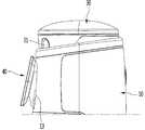
- FIG. 1is a perspective view of a robot according to an embodiment of the present invention.
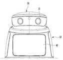
- FIG. 2is a diagram illustrating a state in which the head unit and the display unit of the robot shown in FIG. 1 are tilted upward.
- 3A to 3Care schematic diagrams illustrating a state in which a head unit and a display unit of a robot according to an embodiment of the present invention tilt with respect to a case.
- FIGS. 4A to 4Care schematic diagrams showing a state in which a head unit of a robot according to an embodiment of the present invention rotates with respect to a case.
- 5A to 5Care schematic diagrams illustrating a case of a robot according to an embodiment of the present invention tilting with respect to the base.
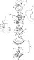
- FIG. 6is an exploded perspective view of a robot according to an embodiment of the present invention.
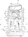
- FIG. 7is a cross-sectional view showing the inside of a robot according to an embodiment of the present invention.
- FIG. 8is a perspective view showing a state in which a case of a robot according to an embodiment of the present invention is removed.
- FIG. 9is a view as viewed from a different direction in a state in which the case of the robot according to the embodiment of the present invention is removed.
- FIG. 10is a view for explaining a driving mechanism according to an embodiment of the present invention.
- FIG. 11is an enlarged view of a part of the driving mechanism shown in FIG. 10.
- FIG. 12is a view of the driving mechanism shown in FIG. 10 viewed from a different direction.
- FIG. 13is an enlarged cross-sectional view of an upper part of the inside of the robot according to an embodiment of the present invention.
- 14A and 14Bare side views illustrating a process of tilting the head unit and the display unit according to an exemplary embodiment of the present invention.
- 15A and 15Bare views for explaining a process of rotating a head unit according to an exemplary embodiment of the present invention.
- 16is a perspective view of an inner frame according to an embodiment of the present invention.
- FIG. 17is a view of the inner frame shown in FIG. 16 viewed from a different direction.
- FIG. 18is a view showing a base plate and a column according to an embodiment of the present invention.
- 19is a diagram for explaining a process in which a case is tilted with respect to a base according to an embodiment of the present invention.
- FIG. 1is a perspective view of a robot according to an embodiment of the present invention
- FIG. 2is a view showing a state in which the head unit and the display unit of the robot shown in FIG. 1 are tilted upward.
- the robotmay include a case 10, a head unit 30, and a display unit 40.
- the case 10may form the exterior of the robot.
- the case 10may have a substantially hollow cylinder shape. It is preferable that the case 10 has a streamlined body.
- An inner spacemay be formed in the case 10.
- the upper surface of the case 10may be open.
- a sensor device 49may be provided on the front portion of the case 10.
- the sensor device 49may include at least one of a depth camera and a lidar.
- the head unit 30may protrude upward from the case 10.
- the head unit 30may include a first display 31.
- the first display 31may be referred to as a head display.
- the first display 31may face forward.
- the head unit 30may be arranged to be tiltable up and down. In more detail, the head unit 30 may rise and tilt upward, or may descend and tilt downward.
- the head unit 30When the head unit 30 is tilted downward, at least a part of the head unit 30 may be accommodated in the case 10. Also, the first display 31 may be hidden in the case 10.
- the head unit 30When the head unit 30 is tilted upward, at least a part of the head unit 30 may protrude upward of the case 10.
- the first display 31may protrude upward from the case 10.
- the head unit 30When the head unit 30 is tilted upward, the direction in which the first display 31 faces may be tilted upward. When the head unit 30 is tilted downward, the direction in which the first display 31 faces may be tilted downward.
- the display unit 40may be disposed in front of the case 10.
- the display unit 40may include a second display 41.
- the second display 41may be referred to as a main display.
- the second display 41may face forward.
- the display unit 40may be arranged to be tiltable vertically. In more detail, the display unit 40 may move forward and tilt upward, or may move backward and tilt downward.
- the rear surface of the display unitmay be in contact with or adjacent to the case 10.
- the rear surface of the display unit 40may be spaced apart from the case 10.
- the direction in which the second display 41 facesmay be tilted upward.
- the direction in which the second display 41 facesmay be tilted downward.
- the robot according to the embodiment of the present inventionmay include a head receiving cover 32.
- the head receiving cover 32may cover the open upper surface of the case 10 from the upper side.
- the head receiving cover 32may be located under the head unit 30.
- the head receiving cover 32may be concavely formed downward. At least a portion of the head unit 30 may be accommodated in the head receiving cover 32.
- the head accommodating cover 32may prevent foreign substances from entering the case 10 through the case 10 and the head unit 30 when the head unit 30 is tilted upward.
- the robot according to the embodiment of the present inventionmay include a base 20.
- the base 20may be located under the case 10.
- the size of the base 20 in the horizontal directionmay be larger than the size of the case 20 in the horizontal direction.
- the height of the base 20may be lower than the height of the case.
- the base 20may be formed with a recessed portion 22 that is concave downward from the upper surface of the base 20.
- the case 10may be located above the depression 22.
- the base 20may be provided with traveling devices 24A and 24B (see FIG. 6 ).
- the traveling devices 24A and 24Bcan drive the robot.
- at least one sensor for sensing the surrounding environment of the robotmay be provided on the base 20.
- a plurality of ultrasonic sensorsmay be provided on the base 20.
- 3A to 3Care schematic diagrams illustrating a state in which a head unit and a display unit of a robot according to an embodiment of the present invention tilt with respect to a case.
- the robot according to an embodiment of the present inventionmay enter one of an inactive mode, a standby mode, and an active mode according to a user's command or a preset condition.
- the inactive modemay include a case in which the robot is in an off state.
- the head unit 30 and the display unit 40may be gradually tilted upward toward the inactive mode, the standby mode, and the active mode.
- the robotwhen the robot is in an inactive mode, at least a portion of the head unit 30 may be accommodated in the case 10 as shown in FIG. 3A.
- the first display 31 of the head unit 30may be hidden in the case 10. Accordingly, the first display 31 can be safely protected and unnecessary power consumption can be prevented.
- the rear surface of the display unit 40may be in contact with or adjacent to the case 10.
- the display unit 40may be mounted on the unit mounting portion 13.
- the unit seating portion 13may be formed by a portion of the front surface of the case 10 being recessed to the rear.
- a part of the head unit 30may protrude to the upper side of the case 10 as shown in FIG. 3B.
- a part of the first display 31 of the head unit 30may protrude upward from the case 10, and another part may be hidden within the case 10.
- the rear surface of the display unit 40may be spaced apart from the case 10.
- the display unit 40may be separated from and spaced apart from the unit mounting portion 13.
- the head unit 30When the robot is in the active mode, at least a part of the head unit 30 may protrude upward from the case 10 as shown in FIG. 3C. In this case, the first display 31 of the head unit 30 may protrude upward from the case 10. Thus, the user can intuitively know that the robot is in the active mode.
- the rear surface of the display unit 40may be further spaced apart from the case 10.
- the display unit 40may be further spaced apart from the unit mounting portion 13.
- the usercan intuitively grasp which mode the robot is in by looking at the head unit 30 and the display unit 40.
- FIGS. 4A to 4Care schematic diagrams showing a state in which a head unit of a robot according to an embodiment of the present invention rotates with respect to a case.
- the head unit 30may rotate left and right with respect to the case 10.
- FIG. 4Ashows the head unit 30 looking forward
- FIG. 4Bshows the head unit 30 rotated in one direction
- FIG. 4Cshows the head unit 30 rotated in the other direction. One figure is shown.
- the first display 31When the head unit 30 is rotated while tilted upward, the first display 31 may not be hidden in the case 10 and may maintain a state protruding upward of the case 10. That is, even if the head unit 30 rotates, the direction in which the first display 31 faces may maintain a direction inclined upward with respect to the horizontal.
- the head unit 30can naturally operate as if a person rotates his or her head.
- the first display 31continues to stare at the user's face and the head unit 30 rotates, the user can feel familiarity with the robot.
- 5A to 5Care schematic diagrams illustrating a case of a robot according to an embodiment of the present invention tilting with respect to the base.
- the case 10may be tilted back and forth with respect to the base 20. Also, the head unit 30 and the display unit 40 may be tilted together with the case 10. Accordingly, the angle range that the head unit 30 and the display unit 40 can face may be larger.
- FIG. 5Ashows the case 10 is not tilted
- FIG. 5Bshows the case 10 tilted forward
- FIG. 5Cshows the case 10 tilted rearward.
- the robotmay include a pillar 25 protruding upward from the base 20, and a tilting shaft 59 may be connected to the pillar 25.
- the case 10may be tilted around the tilting axis 25.
- the pillar 25may protrude from the base 20 to the inside of the case 10.
- the tilting shaft 59may be connected to the upper part of the pillar 25.
- the tilting shaft 59may be formed long in the left and right direction.
- the case 10when the robot advances, the case 10 may be tilted forward. As the forward speed of the robot increases, the case 10 may be further tilted forward. Conversely, when the robot moves backward, the case 10 may be tilted backward. As the reverse speed of the robot increases, the case 10 may be tilted more and more backward.
- the robotmay travel while tilting the case 10 back and forth at a predetermined period. That is, the robot can travel while the case 10 swings back and forth with respect to the base 20.
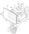
- FIG. 6is an exploded perspective view of a robot according to an embodiment of the present invention
- FIG. 7is a cross-sectional view showing the inside of the robot according to an embodiment of the present invention
- FIG. 8is a case of a robot according to an embodiment of the present invention removed. It is a perspective view showing the state
- FIG. 9is a view as viewed from a different direction in a state in which the case of the robot according to the embodiment of the present invention is removed.
- the case 10may include a front case 11 and a rear case 12.
- the rear case 12may be fastened at the rear of the front case 11.
- the front case 11 and the rear case 12may form an inner space of the case 10 together.
- a unit mounting portion 13 on which the display unit 40 is mountedmay be formed in the case 10.
- the unit seating portion 13may be formed by the front surface of the front case 11 being recessed to the rear.
- the display unit 40may be seated in front of the unit seating portion 13.
- a link through hole 14may be formed in the case 10.
- the link through hole 14may be formed to penetrate back and forth through the unit seating portion 13 of the front case 11.
- a plurality of link through holes 14may be formed.
- the link through hole 14may be a long hole formed vertically.
- the link 130 (refer to FIG. 6) connected to the display unit 40may pass through the link through hole 14.
- the link connector 43(see FIG. 6) of the display unit 40 may be located in the link through hole 14.
- the link 130 connected to the link connector 43may pass through the link through hole 14.
- a through hole 15 in which the sensor device 49 is disposedmay be formed in the case 10.
- the through hole 15may be formed through front and rear penetration in the front surface of the front case 11.
- the through hole 15may be located under the unit seating portion 13.
- the base 20may include a base housing 21 and a base plate 24.
- the base housing 21may form the exterior of the base 20. A space may be formed inside the base housing 21.
- the bottom surface of the base housing 21may be open.
- the base plate 24may cover the open bottom surface of the base housing 21.
- the base plate 24may be disposed horizontally. Traveling devices 24A and 24B may be provided on the base plate 24.
- the traveling devices 24A and 24Bmay include a drive motor 24A and a drive wheel 24B connected to the drive motor 24A.
- Each of the driving motor 24A and the driving wheel 24Bmay be provided with a pair.
- the drive motor 24Amay be accommodated in the inner space of the base housing 21.
- the drive wheel 24Bmay rotate by the power of the drive motor 24A to drive the robot.
- the pillar 25may be formed to be long vertically. Preferably, the pillar 25 may be erected vertically.
- the pillar 25may be formed to protrude upward from the base plate 24. That is, the lower end of the pillar 25 may be supported and fixed by the base plate 24.
- the pillar 25may include a pair of pillar panels 26 spaced from each other in the left and right directions.
- the pillar panel 26may be long vertically.
- a tilting motor 27 for tilting the case 10 with respect to the base 20may be disposed between a pair of pillar panels 26. That is, the tilting motor 27 may be built into the pillar 25. Thereby, the tilting motor 27 can be safely protected.
- a tilting shaft insertion hole 26A into which the tilting shaft 59 is rotatably insertedmay be formed in the upper portion of the pillar 25.
- the tilting shaft insertion hole 26Amay be formed by penetrating left and right above each of the pair of panels 26.
- the tilting motor 27may be located below the tilting shaft 59. That is, the height H1 from the base 20 to the tilting motor 27 may be lower than the height H2 from the base 20 to the tilting shaft 59. Accordingly, even when the tilting shaft 59 is transmitted, the shock transmitted to the tilting motor 27 may be relatively small.
- a pillar through hole 23 through which the pillar 25 passesmay be formed in the base housing 21.
- the pillar through hole 23may be formed by vertically penetrating the base housing 21.
- the pillar 25may pass through the pillar through hole 23 and enter the case 10.
- An opening portion 10A through which the pillar 25 passesmay be formed under the case 10.
- the opening 10Amay be formed through the bottom surface of the case 10.
- the opening portion 10Amay be formed long in front and rear. Therefore, the case 10 can be smoothly tilted with respect to the base 20 without interfering with the pillar 25.
- the base 20may be formed with a recessed portion 22 that is concave downward from the top surface of the base housing 21.
- the case 10may be located above the depression 22.
- the pillar through hole 23may be formed in the depression 22.
- the case 10can be smoothly tilted back and forth without interfering with the base 20.
- the robot according to the embodiment of the present inventionmay include an inner frame 50 that is tiltably fastened to the pillar 25.
- the case 10 connected to the inner frame 50may be tilted back and forth to the base 20. That is, the inner frame 50 may be tilted back and forth together with the case 10.
- the inner frame 50may support parts built into the case 10.
- the inner frame 50may support a rotation motor 91, a lifting motor 101, and a fixed plate 104 to be described later.
- the inner frame 50may support the sensor device 49.
- the inner frame 50may include a pair of main panels 51 spaced left and right.
- the pair of main panels 51may be located opposite to each other based on the pillar 25. That is, the pillar 25 may be positioned between the pair of main panels 51.
- the pair of main panels 51may be disposed in parallel with each other.
- the pair of main panels 51may face each other.
- the inner frame 50may include a supporter 57 that supports the fixing plate 104 and a connection part 56 that connects the supporter 57 and the main panel 51.
- the supporter 57may be fastened to the fixing plate 104.
- the supporter 57may support the fixing plate 104 from the lower side.
- the supporter 57may be disposed vertically.
- the supporter 57may have a plate shape with both sides facing left and right, respectively.
- the supporter 57may be provided with a pair spaced from the left and right.
- a pair of supporters 57may be fastened to the left and right edges of the fixing plate 104, respectively.
- the lifting plate 103 to be described latermay be positioned between a pair of supporters 57.
- connection part 56may be formed in a block shape that is elongated in front and rear.
- the connection part 56may connect the supporter 57 and the main panel 51 between the supporter 57 and the main panel 51.
- connection part 56may be fastened to the outer surface of the upper end of the main panel 51.
- the outer surface of the main panel 51may mean a surface facing the inner surface of the case 10 among both surfaces of the main panel 51.
- connection part 56may be fastened to the inner surface of the lower end of the supporter 57.
- the inner surface of the supporter 57may mean a surface opposite to a surface of the upper surface of the supporter 57 that faces the inner surface of the case 10.
- the inner frame 50may include a connecting bar 52 connecting the pair of main panels 51.
- the connecting bar 52may be a bar formed to be elongated left and right.
- the connecting bar 52may connect the front edge of the pair of main panels 51 to each other.
- the connecting bar 52may connect lower front edges of the pair of main panels 51 to each other.
- the connecting bar 52may be located in front of the pillar 25.
- the connecting bar 52may be hung on the column 25.
- the connecting bar 52may function as a limiter limiting a range in which the inner frame 50 and the case 10 are tilted backward.
- the inner frame 50may include a motor installation part 58 on which an elevating motor 101 to be described later is installed.
- the elevating motor 101may be directly coupled to the motor mounting portion 58, or a elevating motor bracket 101A (see FIG. 9) on which the elevating motor 101 is mounted may be coupled to the motor mounting portion 58.
- the motor installation part 58may be a plate-shaped horizontally or inclinedly disposed.
- the motor installation part 58may support the lifting motor 101 from the lower side.
- the motor installation part 58may be fastened to the protrusion 51C protruding rearward from the main panel 51.
- the protrusion 51Cmay be formed to protrude from the rear edge of the main panel 51 to the rear, and the motor installation part 58 may be fastened from the upper side of the protrusion 51C.
- the protrusion 51Cmay be formed on an upper portion of the rear edge of the main panel 51.
- the motor installation part 58may connect the protrusions 51C formed on the pair of main panels 51 to each other.
- the inner frame 50may include a rear panel 53 facing the rear.
- the rear panel 53may be fastened at the rear of the pair of main panels 51.
- the rear panel 53may connect rear edges of the pair of main panels 51 to each other.
- the rear panel 53may be connected to a lower portion of the rear edge of the pair of main panels 51. That is, the rear panel 53 may be located under the protrusion 51C.
- the length of the rear panel 53 in the left and right directionsmay be longer than the distance between the pair of main panels 51 in the left and right directions.
- Various circuit boards required for driving the robotmay be mounted on the rear surface of the rear panel 53.
- the inner frame 50may include at least one reinforcing panel 54 connecting the main panel 51 and the rear panel 53.
- the reinforcement panel 54may connect the outer surface of the main panel 51 and the front surface of the rear panel 53.
- some of the plurality of reinforcing panels 54may connect the outer surface of one main panel 51 and the front of the rear panel 53, and other parts are the outer surface of the other main panel 51 and the rear panel ( 53) can be connected.
- the reinforcing panel 54is preferably connected to each of the main panel 51 and the rear panel 53 so as to be orthogonal.
- the inner frame 50may support the sensor device 49.
- the sensor device bracket 55 on which the sensor device 49 is mountedmay be fastened to the inner frame 50.
- the sensor device bracket 55may be fastened to at least one of the pair of main panels 51.
- the display unit 40includes a second display 41, a rear cover 42 covering the second display 41 from the rear, and a link connector 43 provided on the rear cover 42. can do.
- the rear cover 42may contact the unit seating portion 13 of the front case 11.
- the link connector 43may be provided on the rear surface of the rear cover 42.
- the link connector 43may be inserted into the link through hole 14 of the front case 11.
- a link 130 to be described latermay be connected to the link connector 43.
- the robot according to the exemplary embodiment of the present inventionmay include a tilting mechanism for tilting the head unit 30 and the display unit 40 together.
- the robot according to the embodiment of the present inventionmay include a rotation mechanism for rotating the head unit 30.
- the tilting mechanism and the rotation mechanismmay be collectively referred to as a driving mechanism.
- the tilting mechanismmay include an elevation motor 101, an elevation plate 103, a fixed plate 104, a contact bar 105, a first guide body 110, and a link 130. have.
- the lifting motor 101may be built into the case 10.
- the lifting motor 101may be installed on the motor installation part 58 of the inner frame 50.
- the lifting motor 101may lift the lifting plate 103.
- the lifting plate 103may be disposed to be inclined in a direction in which the height decreases toward the front.
- the present inventionis not limited thereto, and the lifting plate 103 may be disposed horizontally.
- the lifting plate 103may be located above the connection portion 56 of the inner frame 50.
- the lifting plate 103may be positioned between a pair of supporters 57 of the inner frame 50.
- the fixing plate 104may be located on the upper side of the lifting plate 103.
- the fixing plate 104may be positioned between the head unit 30 and the lifting plate 103.
- the fixed plate 104may be disposed in parallel with the lifting plate 104.
- the fixing plate 104may be fastened to and supported by the supporter 57 of the inner frame 50.
- At least one guide bar 106 for guiding the lifting of the lifting plate 103may be connected to the fixed plate 104.
- the guide bar 106may be formed to be long vertically.
- the upper end of the guide bar 106may be fastened to the fixing plate 104.
- the guide bar 106may pass through the elevation plate 103 to guide the elevation of the elevation plate 103.
- a plurality of guide bars 106are provided. Some of the plurality of guide bars 106 may be connected to one side of the fixing plate 104, and some of the guide bars 106 may be connected to the other side of the fixing plate 104.
- the lower end of the guide bar 106may be connected to the guide bar fixing part 107.
- the guide bar fixing part 107may firmly fix the guide bar 106 together with the fixing plate 104.
- the guide bar fixing portion 107may be formed to be elongated in front and rear.
- the guide bar fixing part 107may have a plate shape formed parallel to the fixing plate 104.
- a pair of guide bar fixing portions 107may be provided.
- a guide bar 106 connected to one side of the fixing plate 104is connected to one of the pair of guide bar fixing portions 107, and a guide bar 106 connected to the other side of the fixing plate 104 is connected to the other. Can be connected.
- the guide bar fixing part 107may be located under the connection part 56 of the inner frame 50.
- the guide bar fixing part 107may be fastened to the bottom surface of the connection part 56.
- the guide bar fixing partmay protrude forward and backward than the connection part 56.
- the guide bar 106may be connected to a portion of the guide bar fixing portion 107 that protrudes before and after the connection portion 56.
- the guide bar 106may pass through the connection part 56 of the inner frame 50 and be connected to the guide bar fixing part 107, or the lower end of the guide bar 106 may be directly connected to the connection part 56 Of course.
- the contact bar 105may be connected to the head unit 30.
- the upper end of the contact bar 105is connected to the head unit 30, and the lower end of the contact bar 105 may be maintained in contact with the lifting plate 103.
- the contact bar 105is preferably in line contact with the lifting plate 103.
- the contact bar 105may be connected to the head unit 30 through the fixing plate 104 and the head receiving cover 32.
- An open hole 104B through which the contact bar 105 passesmay be formed in the fixing plate 104.
- a through hole 32A through which the contact bar 105 passesmay be formed in the head receiving cover 32.
- the contact bar 105may be formed to be bent in a direction in which the height increases toward the front.
- the contact bar 105may be formed to be bent in a direction closer to the vertical as it goes upward.
- the contact bar 105may have an arc shape. Therefore, when the lifting plate 103 presses the contact bar 105 upward, the head unit 30 may not only rise, but may be tilted upward.
- the first guide body 110may be positioned above the fixing plate 104.
- the first guide body 110may be positioned between the fixing plate 104 and the head receiving cover 32.
- the first guide body 110may have a substantially disk shape.
- a head receiving cover 21may be fastened to the first guide body 110.
- the first guide body 110may guide the movement of the contact bar 105.
- the contact bar 105may pass through the first guide body 110.
- the link 130may connect the lifting plate 103 and the fixing plate 104 to the display unit 40.
- the link 130may be connected to the link connector 43 of the display unit 40.
- the link 130may be rotatably connected to the first connector 103A provided on the lifting plate 103.
- the first connector 103Amay be fastened to the bottom of the lifting plate 103.
- the first connector 103Amay be elongated in the front-rear direction.
- the first connector 103Amay protrude forward from the lifting plate 103.
- the link 130may be rotatably connected to the front end of the first connector 103A.
- the link 130may be rotatably connected to the second connector 104A provided on the fixing plate 104.
- the second connector 104Amay be fastened to the upper surface of the fixing plate 104.
- the second connector 104Amay be fastened to the front edge of the fixing plate 104.
- the link 130may be directly connected to the front edge of each of the elevating plate 103 and the fixing plate 104.
- the length of the link 130 in the front-rear directionmay increase, and the display unit 40 may be moved forward and tilted upward. Conversely, when the lifting plate 103 descends, the length of the link 130 in the front and rear direction may be reduced, and the display unit 40 may be moved backward and tilted downward.
- the rotation mechanismmay include a rotation motor 91, a rotation wheel 92, a wire W, a first guide body 110, and a second guide body 120.
- the rotation motor 91may be built into the case 10.
- the rotation motor 91may be installed on the inner frame 50.
- the rotation motor bracket 91A on which the rotation motor 91 is mountedmay be installed on the inner frame 50.
- the rotation motor bracket 91Amay be fastened in front of the inner frame 50.
- the rotation motor bracket 91Amay connect the front edges of the pair of main panels 51 to each other.
- the rotation motor bracket 91Amay be located above the connecting bar 52.
- the rotary motor 91 mounted on the rotary motor bracket 91Amay be positioned between a pair of main panels 51. Thereby, the rotary motor 91 can be safely protected.
- the rotation motor 91may be located at a lower height than the lifting motor 101.
- the height H3 from the base 20 to the rotary motor 91may be lower than the height H4 from the base 20 to the lifting motor 101.
- the rotation motor 91may rotate the head unit 30.
- the rotation motor 91may rotate the first guide body 110, and the head unit 30 and the contact bar 105 may rotate together with the first guide body 110. That is, the first guide body 110 may be rotatably disposed on the upper side of the fixing plate 104.
- the rotating wheel 92may be connected to the rotating motor 91.
- the rotating wheel 92may be located in front of the rotating motor bracket 91A.
- the wire Wmay transmit the rotational force of the rotating wheel 92 to the first guide body 110.
- the wire Wmay form a single closed curve surrounding a part of the outer circumference of the first guide body 110 and a part of the outer circumference of the rotating wheel 92.
- the second guide body 120may guide the rotation of the first guide body 110.
- the second guide body 120may be fixed to the upper side of the fixing plate 104.
- the second guide body 120may have a ring shape surrounding the outer circumference of the first guide body 110.
- the second guide body 120may also include at least one arc.
- the height of the second guide body 120may be lower than the height of the first guide body 110. Accordingly, the second guide body 120 may surround the lower portion of the outer circumference of the first guide body 110.
- the rotation motor 91rotates the rotation wheel 92
- the rotational force of the rotation wheel 92may be transmitted to the first guide body 110 by a wire W.
- the first guide body 110is guided from the inside of the second guide body 120 and can rotate.
- the contact bar 105 passing through the first guide body 110 and the head unit 30 connected to the contact bar 105may rotate together with the first guide body 110.
- the first guide body 110may be fastened to the bottom surface of the head receiving cover 32. Accordingly, the head receiving cover 32 may also rotate together with the first guide body 110.
- the present inventionis not limited thereto, and when the head receiving cover 32 is fixed to the case 10 without being fastened to the first guide body 110, the head receiving cover 32 may not rotate.
- FIG. 10is a view for explaining a driving mechanism according to an embodiment of the present invention
- FIG. 11is an enlarged view of a part of the driving mechanism shown in FIG. 10
- FIG. 12is a view showing another driving mechanism shown in FIG. It is a view as viewed from the direction
- FIG. 13is an enlarged cross-sectional view of an upper part of the inside of the robot according to the embodiment of the present invention.
- the first guide body 110may include a lower body 111, a middle body 112, and an upper body 113.
- the lower body 111, the middle body 112, and the upper body 113may be coupled to each other to rotate together. Two or more of the lower body 111, the middle body 112, and the upper body 113 may be integrally formed.
- the lower body 111may have a disk shape.
- the lower body 111may be rotatably disposed on the upper side of the fixing plate 104.
- the lower body 111may be located inside the second guide body 120. That is, the second guide body 120 may surround the outer circumference of the lower body 111.
- the middle body 112may have a disk shape.
- the middle body 112may be fastened to the upper surface of the lower body 111.
- the middle body 112may be positioned between the lower body 111 and the upper body 113.
- a wire Wmay be wound around a part of the outer circumference of the middle body 112.
- the wire Wmay rotate the middle body 112 without sliding with respect to the middle body 112.
- at least one locking portion(for example, a knot) may be formed in the wire W, and a locking groove for engaging the locking portion may be formed on the outer circumference of the middle body 112.
- the diameter of the middle body 112may be smaller than the diameter of the lower body 111 and the upper body 113. Therefore, the wire W may not be separated upward or downward.
- the upper body 113may have a disk shape.
- the upper body 113may be located above the middle body 112.
- the upper body 113may be fastened with the head receiving cover 32.
- the lower body 111, the middle body 112, and the upper body 113may have bar through-holes 110A through which the contact bar 105 passes.
- a guide rib 110Bmay be formed in the first guide body 110 to fit into the guide groove 105A formed in the contact bar 105.
- the guide groove 105Ais preferably formed on both sides of the contact bar 105.
- the guide groove 105Amay be formed long in the length direction of the contact bar 105. That is, the guide groove 105A may be formed longer in a direction toward the front as it goes upward.
- a guide blockmay be fastened to the upper body 113, and a guide rib 110B may be formed on the guide block.
- the guide blockmay be fastened to the upper surface of the middle body 112.
- the present inventionis not limited thereto, and the guide rib 110B may be formed to protrude inward from at least one of the lower body 111, the middle body 112, and the upper body 113 bar through hole 110A Do.
- a stopper 105Bmay be provided at the lower end of the contact bar 105.
- the stopper 105Bmay be caught on the bottom of the fixed plate 104 when the lifting plate 103 rises to a predetermined height.
- the stopper 105Bmay have a pin shape that is elongated to the left and right.
- the stopper 105Bmay have a length that does not pass through the open hole 104B formed in the fixing plate 104.
- the opening hole 104B formed in the fixing plate 104may be larger than the bar through hole 110A formed in the first guide body 110. This is because the contact bar 105 rotating together with the first guide body 110 is formed to be bent, so that the radius of rotation of the contact bar 105 increases toward the lower side.
- the inner diameter of the second guide body 120may be larger than the bar through-hole 110A formed in the first guide body 110.
- the inner diameter of the second guide body 120may be the same as or similar to the open hole 104B formed in the fixing plate 104.
- the contact bar 105can be easily rotated without interfering with the fixing plate 104 and the second guide body 120.
- the second guide body 120may be provided with a separation preventing unit 121 that prevents separation of the first guide body 110.
- the departure prevention part 121may be fastened to the upper surface of the second guide body 120.
- the departure prevention part 121may have an approximately arc shape, but is not limited thereto.
- a plurality of separation prevention units 121may be provided.
- the plurality of separation preventing portions 121may be spaced apart from each other in the circumferential direction of the second guide body 120.
- the wires Wmay pass between the separation preventing portions 121 adjacent to each other.
- the departure prevention part 121may protrude into the second guide body 120.
- a part of the separation prevention part 121may be located above the lower body 111. As a result, the lower body 111 may be constrained in the vertical direction.
- a wire support wheel 93 and a wheel supporter 94may be provided on the fixing plate 104.
- the wire support wheel 93may support the wire W in contact with the wire W.
- the wire support wheel 93may rotate around a rotating shaft formed long in the left and right directions.
- the wheel supporter 94may rotatably support the wire support wheel 93.
- the wheel supporter 94may be provided on the upper surface of the fixing plate 104.
- the wheel supporter 94may be provided at the front of the fixing plate 104.
- the wire Wmay contact the wire support wheel 93 and pass through the inside of the wheel supporter 94.
- the wheel supporter 94may include a pair of support portions supporting the rotational axis of the wire support wheel 93 at both sides of the wire support wheel 93, and a connection portion connecting the upper portions of the pair of support portions to each other. have.
- the wire Wmay pass between the pair of supports. When the tension applied to the wire W is weakened, the connecting portion may prevent the wire W from being separated from the wheel supporter 94 upward.
- An avoidance groove 104C through which the wire W passesmay be formed in the fixing plate 104.
- the avoidance groove 104Cmay be formed by a front edge of the fixing plate 104 being recessed backward.
- the wheel supporter 94may be located above the avoidance groove 104C. This allows the wire W to contact the wire support wheel 93 without interfering with the fixed plate 104.
- the wire Wis supported by the wire support wheel 93 and can be turned.
- a portion between the rotation wheel 92 and the wire support wheel 93 among the wires Wmay be steeper than a portion between the wire support wheel 93 and the first guide body 110.
- the virtual rotation axis X1 of the rotation wheel 91 and the virtual rotation axis X2 of the first guide body 110may not be parallel to each other.
- the virtual rotation axis X1 of the rotation wheel 91may be closer to the horizontal than the vertical
- the virtual rotation axis X2 of the first guide body 110may be closer to the vertical than the horizontal.
- the wire Wis supported by the wire support wheel 93 and the direction is changed, so that the rotational force of the rotating wheel 91 can be easily transmitted to the first guide body 110.
- Each of the wire support wheel 93 and the wheel supporter 94may be provided with a pair.
- Any one wire support wheel 93may support a portion of the rotating wheel 92 toward the first guide body 110.
- the other wire support wheel 93may support a portion of the first guide body 110 toward the rotation wheel 92.
- the link 130may connect the lifting plate 103 and the fixing plate 104 to the display unit 40.
- a plurality of links 130may be provided.
- the link 130may be provided with a pair of left and right spaced apart.
- the display unit 40may include a pair of link connectors 43.
- the lifting plate 103may be provided with a pair of first connectors 103A
- the fixing plate 104may be provided with a pair of second connectors 104A.
- the link 130may include at least a pair of link bars 131 and 132 crossing each other.
- the link 130includes a pair of link bars 131 and 132 will be described as an example.
- the link 130may include a first link bar 131 and a second link bar 132.
- the first link bar 131 and the second link bar 132cross each other to form a joint 133.
- the first link bar 131may be rotatably connected to the link connector 43 of the display unit 40.
- the first link bar 131may be rotatably connected to the first connector 103A provided on the lifting plate 103. That is, the front end of the first link bar 131 may be rotatably connected to the link connector 43, and the rear end may be rotatably connected to the first connector 103A.
- the second link bar 132may be connected to be movable along the long hole 43A formed in the link connector 43 of the display unit 40.
- the second link bar 132may be rotatably connected to the second connector 104A provided on the fixing plate 104. That is, the front end of the second link bar 132 may be movably connected along the long hole 43A formed in the link connector 43, and the rear end may be rotatably connected to the second connector 104A.
- the long hole 43Amay be formed by penetrating left and right through the link connector 43.
- the long hole 43Amay be formed to be long vertically.
- the long hole 43Amay be formed below a portion of the link connector 43 to which the first link bar 131 is connected.
- a protrusion 134 inserted into the long hole 43Amay be formed at the front end of the second link bar 132.
- the protrusion 134may protrude in a direction perpendicular to the one surface from one surface facing the link connector 43 among both surfaces of the second link bar 132.
- the protrusion 134may move between both ends of the long hole 43A while being fitted in the long hole 43A.
- the display unit 40may not only move forward, but may be tilted upward.
- the power of the lifting motor 101may be transmitted to the lifting plate 103 by the power transmission unit 102.
- the power transmission unit 102may convert the rotational force of the lifting motor 101 into a force acting in the lifting direction of the lifting plate.
- the power transmission unit 102may include a first arm 102A (see FIGS. 14A and 14B) and a second arm 102B (see FIGS. 14A and 14B).
- the first arm 102Amay be connected to the lifting motor 101.
- the second arm 102Bmay be rotatably connected to the first arm 102A and rotatably connected to the lower side of the lifting plate 103.
- one end of the first arm 102Amay be connected to the rotation shaft of the lifting motor 101 and the other end may be rotatably connected to the second arm 102B.
- the second arm 102Bmay be formed to be curved in a direction in which the height increases toward the front.
- the second arm 102Bmay bend in a direction closer to the vertical as it goes forward.
- One end of the second arm 102Bmay be rotatably connected to the first arm, and the other end may be rotatably connected to a female connector 103B (see FIGS. 14A and 14B) provided on the lifting plate 103. have.
- the female connector 103Bmay be fastened to the bottom of the lifting plate 103.
- 14A and 14Bare side views illustrating a process of tilting the head unit and the display unit according to an exemplary embodiment of the present invention.
- the elevating plate 103may elevate between the first position P1 and the second position P2 above the first position P1.
- the distance (L1) between the lifting plate 103 and the fixed plate 104is, when the lifting plate 103 is located in the second position (P2).
- itmay be longer than the distance (L2) between the lifting plate 103 and the fixed plate 104.
- the lifting plate 103When the lifting plate 103 is located in the first position P1, the first display 31 of the head unit 30 can be hidden in the case 10 and the display unit 40 is the outer surface of the case 10. It can be adjacent to or adjacent to.
- the lifting plate 103When the lifting plate 103 is located in the second position P2, the first display 31 of the head unit 30 protrudes upward from the case 10, and the display unit 40 is in front of the case 10. Can be separated.
- the first display 31 and the second display 41may be tilted upward, respectively.
- the head unit 30may move upward and tilt upward, and the display unit 40 may move forward and tilt upward. Conversely, when the lifting plate 103 descends, the head unit 30 moves downward and tilts downward, and the display unit 40 may move backward and tilt downward.
- the angle variable amount (a1) in the direction in which the first display 31 facesis the second display 41 It may be different from the angle variable amount (a2) in the facing direction.
- the first display 31when the lifting plate 130 is located in the first position P1, the first display 31 may face the first direction D1, and the second display 41 may be in the second direction D2. Can face.
- the first display 31When the lifting plate 130 is located in the second position P2, the first display 31 may face the third direction D3 and the second display 41 may face the fourth direction D4.
- the third direction D3may be a direction tilted upwards than the first direction D1, and the fourth direction D4 may be a direction tilted upwards than the second direction D2.
- the angle (a1) formed by the third direction (D3) and the first direction (D1)may be different from the angle (a2) formed by the fourth direction (D4) and the second direction (D2). have.
- the power transmission unit 102may push the lifting plate 103 upward.
- the lifting plate 103is guided by the guide bar 106 and can rise.
- the lifting plate 103rises and can push the contact bar 105 upward.
- the contact bar 105is guided by the first guide body 110 and can move upward. At this time, the lower end of the contact bar 105 maintains contact with the upper surface of the lifting plate 103 and may slide forward.
- the head unit 30 connected to the upper end of the contact bar 105can be moved upward and tilted upward. .
- the first connector 103Amay also rise. Therefore, the first link bar 131 rotates with respect to the first connector 103A and the link connector 43, and the inclination may be gentle. That is, the length of the first link bar 131 in the front-rear direction may increase. Since the second link bar 132 crosses the first link bar 131 and forms a joint 133, the second link bar 132 rotates with respect to the second connector 104A and the link connector 103 The slope can be gentle. That is, the length of the second link bar 132 in the front-rear direction may increase.
- the protrusion of the second link bar 132may move from the lower end of the long hole 43A to the upper end. Accordingly, the display unit 40 may move forward and tilt upward at the same time.
- the power transmission unit 102may pull the lifting plate 103 downward.
- the lifting plate 103is guided by the guide bar 106 and can be lowered.
- the contact bar 105When the lifting plate 103 descends, the contact bar 105 may descend due to the load of the head unit 30 and the weight of the contact bar 105. The contact bar 105 is guided by the first guide body 110 and can move downward. At this time, the lower end of the contact bar 105 is kept in contact with the upper surface of the lifting plate 103 and may slide backward.
- the head unit 30 connected to the upper end of the contact bar 105can be moved downward and tilted downward. .
- the first connector 103Amay also descend. Accordingly, the first link bar 131 may rotate with respect to the first connector 103A and the link connector 43, and the inclination may be steep. That is, the length of the first link bar 131 in the front-rear direction may be reduced. Since the second link bar 132 crosses the first link bar 131 and forms a joint 133, the second link bar 132 rotates with respect to the second connector 104A and the link connector 103 The slope can be steep. That is, the length of the second link bar 132 in the front-rear direction may be reduced.
- the protrusion of the second link bar 132may move from the top to the bottom of the long hole 43A. Accordingly, the display unit 40 can be tilted downward while moving backward.
- the head unit 30 and the display unit 40be tilted up and down at the same time using a single lift motor 101, but also the degree to which the head unit 30 and the display unit 40 are tilted can be controlled. They can be adjusted differently.
- 15A and 15Bare views for explaining a process of rotating a head unit according to an exemplary embodiment of the present invention.
- the wire Wcan transmit the rotational force of the rotation wheel 92 to the first guide body 110, and the first guide body 110 It can rotate clockwise at the same time as the rotary wheel 92.
- the first guide body 110is guided by the second guide body 120 and can rotate.
- the rotational force of the rotating wheel 92can be smoothly transmitted to the first guide body 110.
- the contact bar 105may rotate together with the first guide body 110. At this time, the lower end of the contact bar 105 may slide while maintaining contact with the upper surface of the lifting plate 103. Since the contact bar 105 is formed to be bent, the head unit 30 connected to the upper end of the contact bar 105 can be rotated clockwise while maintaining a tilted state.
- the wire Wmay transmit the rotational force of the rotation wheel 92 to the first guide body 110, and the first guide body 110 It can rotate counterclockwise at the same time as the rotary wheel 92.
- the contact bar 105may rotate together with the first guide body 110. At this time, the lower end of the contact bar 105 may slide while maintaining contact with the upper surface of the lifting plate 103. Since the contact bar 105 is formed to be bent, the head unit 30 connected to the upper end of the contact bar 105 can be rotated counterclockwise while maintaining a tilted state.
- the rotation motor 91may rotate only the head unit 30 and not the display unit 40. In addition, the rotation motor 91 may rotate the head unit 31 regardless of the degree of tilting of the head unit 30. In addition, since the lower end of the contact bar 105 rotates while maintaining contact with the upper surface of the lifting plate 103, the head unit 30 may rotate while maintaining the tilted state.
- the rotation wheel 92 and the first guide body 110are connected by the wire W, the virtual rotation axis X1 of the rotation wheel 92 (refer to FIG. 10) and the first guide body 110
- the virtual axis of rotation (X2)does not need to be parallel. Therefore, since the space in the case 10 can be efficiently utilized, the robot can be compact.
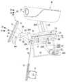
- FIG. 16is a perspective view of an inner frame according to an embodiment of the present invention
- FIG. 17is a view viewed from a different direction of the inner frame shown in FIG. 16
- FIG. 18is a base plate and a support column
- FIG. 19is a diagram for explaining a process in which a case is tilted with respect to a base according to an embodiment of the present invention.
- the sensor device bracket 55 on which the sensor device 49 is mountedmay be fastened to the inner frame 50.
- the sensor device bracket 55may be fastened to at least one of the pair of main panels 51.
- the sensor device bracket 55may include a connection arm 55A connected to the inner frame 50 and a fastening portion 55B connected to the connection arm 55A and mounted with the sensor device 49.
- connection arm 55Amay be long disposed approximately in front and rear.
- the connection arm 55Amay separate the fastening portion 55B and the sensor device 49 from the inner frame 50.
- the fastening portion 55Bmay be orthogonal to the connection arm 55A.
- the sensor device 49may be fastened to the front surface of the fastening portion 55B.
- the pillar 25may include at least one inner connector 29 connecting the pair of pillar panels 26 to each other.
- the inner connector 29may be positioned between a pair of pillar panels 26. As a result, the structure of the pillar 25 can be made more solid.
- the pillar 25may be located within the inner frame 50.
- the pillar 25may be positioned between the pair of main panels 51 in the left and right direction, and may be positioned between the connecting bar 52 and the rear panel 53 in the front and rear direction.
- the pillar 25may be positioned between the rotation motor bracket 91A and the rear panel 53 in the front-rear direction.
- a through hole 51B into which the tilting shaft 59 is insertedmay be formed in the inner frame 50.
- the through hole 51Bmay be formed by penetrating left and right above each main panel 51.
- the tilting shaft 59may be inserted through the through hole 51B formed in the inner frame 50 and the tilting shaft insertion hole 26A formed in the pillar 25. Accordingly, the inner frame 50 can be tilted back and forth with respect to the pillar 25.
- the inner frame 50may be positioned above the recessed portion 22 of the base 20.
- the inner frame 50may be spaced apart from the upper side of the depression 22.
- Guide long holes 51Amay be formed in the inner frame 50.
- the guide long hole 51Amay be formed in at least one of the pair of main panels 51.
- the guide long hole 51Amay be formed to penetrate right and left under the main panel 51.
- the guide long hole 51Amay be formed to be long vertically.
- a lever 28may be connected to the tilting motor 27.
- the lever 28may transmit the rotational force of the tilting motor 27 to the inner frame 50 to tilt the inner frame 50.
- the lever 28may include a motor connection portion 28A, a lever body 28B, and a long hole insertion portion 28C.
- the motor connection part 28Amay be connected to the tilting motor 27.
- the lever body 28Bmay be elongated in a direction perpendicular to the rotation axis of the tilting motor 27 in the motor connection part 28A.
- the rotating shaft of the tilting motor 27may be formed to be long left and right, and the lever body 28B may be formed to be long vertically.
- the long hole insertion part 28Cmay protrude from the lever body 28B in a direction parallel to the rotation axis of the tilting motor 27.
- the long hole insertion portion 28Cmay be movably inserted into the guide long hole 51A formed in the inner frame 50.
- the long hole insertion portion 28C of the lever 28is a guide long hole 51A Moving from the lower end of the long hole to the upper end, the inner frame 50 may be inclined forward around the tilting axis (59).
- the case 10 and the head unit 30 and the display unit 40 mounted theretomay be tilted forward together with the inner frame 51.
- the long hole insertion portion 28C of the lever 28is a guide long hole 51A Moving from the lower end of the long hole to the upper end, the inner frame 50 may be inclined rearward around the tilting axis 59. Accordingly, the case 10 and the head unit 30 and the display unit 40 mounted thereon may be tilted rearward together with the inner frame 51.
Landscapes
- Engineering & Computer Science (AREA)
- Robotics (AREA)
- Mechanical Engineering (AREA)
- Health & Medical Sciences (AREA)
- Audiology, Speech & Language Pathology (AREA)
- General Health & Medical Sciences (AREA)
- Human Computer Interaction (AREA)
- Toys (AREA)
Abstract
Description
Translated fromKorean본 발명은 로봇에 관한 것으로, 좀 더 상세히는 헤드를 갖는 로봇에 관한 것이다.The present invention relates to a robot, and more particularly, to a robot having a head.
공장 자동화의 일 부분을 담당하기 위해, 로봇은 산업용으로 개발되어 왔다. 최근에는 로봇을 응용한 분야가 더욱 확대되고 있는바, 의료용 로봇과 우주 항공용 로봇뿐만 아니라 일상 생활에서 사용될 수 있는 로봇도 개발되고 있다.To take on part of factory automation, robots have been developed for industrial use. In recent years, as the field to which robots are applied is further expanding, not only medical robots and aerospace robots, but also robots that can be used in everyday life are being developed.
이러한 일상 생활용 로봇은 사용자의 명령에 응답하여 특정 서비스(예를 들어, 쇼핑, 서빙, 대화, 청소 등)를 제공한다. 또한, 일상 생활용 로봇은 디스플레이를 포함하여 서비스와 관련된 정보, 영상 또는 이미지를 표시한다.These daily life robots provide specific services (for example, shopping, serving, conversation, cleaning, etc.) in response to a user's command. In addition, the robot for everyday life displays information, images, or images related to a service, including a display.
또한, 특정한 일상 생활용 로봇은 사용자에게 친근감을 주기 위해 신체와 유사하도록 헤드와 바디를 포함한다. 이 경우, 상기 헤드에는 로봇의 얼굴 표정 등을 나타내는 헤드 디스플레이가 구비되고, 상기 바디에는 서비스와 관련된 정보, 영상 또는 이미지를 표시하는 바디 디스플레이가 구비될 수 있다.In addition, certain robots for everyday life include a head and a body to resemble a body to give a user a sense of familiarity. In this case, the head may be provided with a head display indicating facial expressions of the robot, and the body may be provided with a body display displaying service-related information, images or images.
다만, 종래의 로봇은 헤드 디스플레이만이 회전 또는 틸팅되고, 바디 디스플레이는 고정되어 움직이지 못하는 문제점이 있다.However, in the conventional robot, only the head display is rotated or tilted, and the body display is fixed and cannot move.
본 발명이 해결하고자 하는 일 과제는, 헤드 유닛과 디스플레이 유닛이 틸팅 가능한 로봇을 제공하는 것이다.One problem to be solved by the present invention is to provide a robot in which a head unit and a display unit are tiltable.
본 발명이 해결하고자 하는 다른 과제는 헤드 유닛과 디스플레이 유닛이 단일 모터에 의해 동시에 틸팅되는 로봇을 제공하는 것이다.Another problem to be solved by the present invention is to provide a robot in which a head unit and a display unit are simultaneously tilted by a single motor.
본 발명의 실시예에 따른 로봇은, 헤드 유닛에 연결된 컨택 바 및 디스플레이 유닛에 연결된 링크가 승강 플레이트에 연결될 수 있다. 따라서, 승강 플레이트의 승강에 의해 헤드 유닛과 디스플레이 유닛이 동시에 틸팅될 수 있다.In the robot according to an embodiment of the present invention, a contact bar connected to the head unit and a link connected to the display unit may be connected to the lifting plate. Accordingly, the head unit and the display unit can be tilted at the same time by the lifting of the lifting plate.
좀 더 상세히, 본 발명의 실시예에 따른 로봇은, 내부 공간이 형성된 케이스; 상기 케이스의 상측으로 돌출되고 제1디스플레이를 갖는 헤드 유닛; 상기 케이스의 전방에 배치되고 제2디스플레이를 갖는 디스플레이 유닛; 상기 케이스에 내장된 승강 모터; 상기 승강 모터의 동력에 의해 제1위치 및 상기 제1위치보다 상측인 제2위치 사이에서 승강하는 승강 플레이트; 상단은 상기 헤드 유닛과 연결되고 하단은 상기 승강 플레이트에 접촉한 상태를 유지하는 컨택 바; 상기 승강 플레이트와 상기 헤드 유닛의 사이에 위치하고 상기 컨택 바가 통과하는 개방공이 형성된 고정 플레이트; 및 상기 승강 플레이트 및 고정 플레이트를 상기 디스플레이 유닛과 연결하는 링크를 포함할 수 있다.In more detail, a robot according to an embodiment of the present invention includes a case in which an inner space is formed; A head unit protruding upward of the case and having a first display; A display unit disposed in front of the case and having a second display; An elevating motor built into the case; A lifting plate for lifting between a first position and a second position higher than the first position by the power of the lifting motor; A contact bar having an upper end connected to the head unit and a lower end contacting the lifting plate; A fixed plate positioned between the lifting plate and the head unit and having an open hole through which the contact bar passes; And a link connecting the lifting plate and the fixed plate to the display unit.
상기 컨택 바는 전방으로 갈수록 높이가 높아지며 수직에 가까워지는 방향으로 휘어지게 형성될 수 있다.The contact bar increases in height toward the front and may be formed to bend in a direction closer to the vertical.
상기 승강 플레이트가 상기 제1위치이면 상기 제1디스플레이는 상기 케이스 내에 숨겨지고, 상기 승강 플레이트가 상기 제2위치이면 상기 제1디스플레이는 상기 케이스의 상측으로 돌출될 수 있다.When the elevation plate is in the first position, the first display may be hidden in the case, and when the elevation plate is in the second position, the first display may protrude upward of the case.
상기 승강 플레이트가 상기 제1위치이면 상기 디스플레이 유닛은 상기 케이스의 외면에 접하고, 상기 승강 플레이트가 상기 제2위치로 상승하면 상기 디스플레이 유닛은 상기 케이스의 외면과 이격될 수 있다.When the lifting plate is in the first position, the display unit contacts the outer surface of the case, and when the lifting plate rises to the second position, the display unit may be spaced apart from the outer surface of the case.
상기 승강 플레이트가 상승하면, 상기 제1디스플레이가 향하는 방향 및 상기 제2디스플레이가 향하는 방향이 상측으로 틸팅될 수 있다.When the lifting plate is raised, a direction toward the first display and a direction toward the second display may be tilted upward.
상기 승강 플레이트가 상기 제1위치에서 상기 제2위치로 상승한 경우에, 상기 제1디스플레이가 향하는 방향의 각도 가변량은 상기 제2디스플레이가 향하는 방향의 각도 가변량과 상이할 수 있다.When the lifting plate is raised from the first position to the second position, an angle variable amount in a direction in which the first display faces may be different from an angle variable amount in a direction in which the second display faces.
상기 승강 모터의 회전력을 상기 승강 플레이트로 전달하는 동력 전달부를 더 포함할 수 있다. 상기 동력 전달부는, 상기 승강 모터에 연결된 제1암; 및 상기 제1암에 회전 가능하게 연결되고 상기 승강 플레이트의 하측에 회전 가능하게 연결된 제2암을 포함할 수 있다.It may further include a power transmission unit for transmitting the rotational force of the lifting motor to the lifting plate. The power transmission unit may include a first arm connected to the lifting motor; And a second arm rotatably connected to the first arm and rotatably connected to a lower side of the elevating plate.
상하로 길게 형성되고 상기 고정 플레이트에 연결되며 상기 승강 플레이트의 승강을 가이드하는 적어도 하나의 가이드바를 더 포함할 수 있다.It may further include at least one guide bar formed vertically and connected to the fixing plate to guide the elevation of the elevation plate.
상기 고정 플레이트의 상측에 배치되고 상기 컨택 바가 통과하는 관통공이 형성되며 상기 헤드의 적어도 일부가 수용되는 헤드 수용커버를 더 포함할 수 있다.It may further include a head receiving cover disposed on the upper side of the fixing plate, a through hole through which the contact bar passes, and accommodating at least a portion of the head.
상기 케이스에는 상기 링크가 통과하는 링크 통과공이 형성될 수 있다.A link through hole through which the link passes may be formed in the case.
상기 링크는, 상기 승강 플레이트에 구비된 제1커넥터에 회전 가능하게 연결된 제1링크바; 상기 고정 플레이트에 구비된 제2커넥터에 회전 가능하게 연결되고, 상기 제1링크바와 교차하며 조인트를 형성하는 제2링크바를 포함할 수 있다.The link may include a first link bar rotatably connected to a first connector provided on the lifting plate; It may include a second link bar rotatably connected to the second connector provided on the fixing plate, crossing the first link bar and forming a joint.
상기 디스플레이 유닛은, 상기 제2디스플레이를 후방에서 커버하는 리어 커버; 및 상기 리어 커버의 배면에 체결되고 상기 링크가 연결되는 링크 커넥터를 포함할 수 있다.The display unit may include a rear cover covering the second display from the rear; And a link connector fastened to the rear surface of the rear cover and connected to the link.
상기 링크는, 상기 링크 커넥터에 회전 가능하게 연결되는 제1링크바; 및 상기 제1링크바와 교차하여 조인트를 형성하고, 상기 링크 커넥터에 형성된 장공을 따라 이동 가능하게 연결된 제2링크바를 포함할 수 있다.The link may include a first link bar rotatably connected to the link connector; And a second link bar intersecting with the first link bar to form a joint and movably connected along a long hole formed in the link connector.
상기 고정 플레이트의 상측에 체결되고 상기 컨택 바의 이동을 가이드하는 가이드 바디를 더 포함할 수 있다.It may further include a guide body fastened to the upper side of the fixing plate to guide the movement of the contact bar.
상기 컨택 바에는 상기 컨택 바의 길이 방향으로 길게 형성된 가이드 홈이 형성되고, 상기 가이드 바디에는 상기 가이드 홈에 끼워지는 가이드 리브가 형성될 수 있다.A guide groove formed long in the length direction of the contact bar may be formed in the contact bar, and a guide rib fitted into the guide groove may be formed in the guide body.
상기 케이스의 하측에 위치한 베이스; 상기 베이스에서 상기 케이스 내로 상방 돌출된 기둥; 상기 기둥에 틸팅 가능하게 체결된 이너 프레임; 및 상기 이너 프레임을 상기 기둥에 대해 틸팅시키는 틸팅 모터를 더 포함할 수 있다. 상기 케이스 및 이너 프레임은 상기 베이스에 대해 함께 틸팅될 수 있다.A base located under the case; A pillar protruding upward from the base into the case; An inner frame tiltably fastened to the pillar; And a tilting motor for tilting the inner frame with respect to the pillar. The case and the inner frame may be tilted together with respect to the base.
상기 이너 프레임의 틸팅 축은 상기 틸팅 모터의 상측으로 이격되게 위치할 수 있다.The tilting axis of the inner frame may be positioned to be spaced apart from the upper side of the tilting motor.
상기 틸팅 모터의 회전력을 상기 이너 프레임으로 전달하는 레버를 더 포함할 수 있다. 상기 레버는, 상기 틸팅 모터에 연결된 모터 연결부; 상기 모터 연결부에서 상기 틸팅 모터의 회전축과 수직한 방향으로 길게 형성된 레버 바디; 및 상기 레버 바디에서 상기 틸팅 모터의 회전축과 나란한 방향으로 돌출되고, 상기 이너 프레임에 형성된 가이드 장공에 이동 가능하게 삽입된 장공 삽입부를 포함할 수 있다.A lever for transmitting the rotational force of the tilting motor to the inner frame may be further included. The lever may include a motor connection part connected to the tilting motor; A lever body elongated in a direction perpendicular to a rotation axis of the tilting motor at the motor connection portion; And a long hole insertion portion protruding from the lever body in a direction parallel to the rotation axis of the tilting motor and movably inserted into a guide long hole formed in the inner frame.
상기 베이스에는, 상기 베이스의 상면에서 하측으로 오목하게 함몰된 함몰부가 형성되고, 상기 케이스는 상기 함몰부의 상측에 위치할 수 있다.In the base, a depression recessed downward from the upper surface of the base may be formed, and the case may be located above the depression.
상기 고정 플레이트 및 승강모터는 상기 이너 프레임에 연결되어 지지될 수 있다.The fixing plate and the lifting motor may be connected to and supported by the inner frame.
본 발명의 바람직한 실시예에 따르면, 제1디스플레이를 갖는 헤드 유닛 및 제2디스플레이를 갖는 디스플레이 유닛이 틸팅 가능하므로, 사용자의 시선 높이에 따른 디스플레이의 경사 조절이 가능한 이점이 있다.According to a preferred embodiment of the present invention, since the head unit having the first display and the display unit having the second display can be tilted, there is an advantage that the inclination of the display can be adjusted according to the height of the user's gaze.
또한, 단일의 승강모터를 사용하여 헤드 유닛 및 디스플레이 유닛의 틸팅이 동시에 가능하므로, 로봇의 구조가 간단해지고 비용이 절감되는 이점이 있다.In addition, since the head unit and the display unit can be tilted at the same time using a single lifting motor, there is an advantage in that the structure of the robot is simplified and cost is reduced.
또한, 컨택 바는 휘어지게 형성되고 하단이 승강 바디에 접촉된 상태로 유지되므로, 헤드 유닛은 상승하는 동시에 상측으로 틸팅될 수 있고, 디스플레이 유닛은 전방으로 이동하는 동시에 상측으로 틸팅될 수 있다. 이로써 헤드 유닛 및 디스플레이 유닛의 동작이 자연스러워질 수 있다.In addition, since the contact bar is formed to be bent and the lower end is maintained in contact with the lifting body, the head unit can be tilted upward while ascending, and the display unit can be moved forward and tilted upward. Accordingly, the operation of the head unit and the display unit can be made smooth.
또한, 헤드 유닛의 제1디스플레이는 틸팅 정도에 따라 케이스 내에 숨겨지거나 케이스의 상측으로 돌출될 수 있다. 이로써, 사용자는 로봇의 동작 모드를 직관적으로 파악할 수 있다.In addition, the first display of the head unit may be hidden in the case or protruded upward of the case depending on the degree of tilting. Accordingly, the user can intuitively grasp the operation mode of the robot.
또한, 헤드 유닛이 향하는 방향의 경사 가변량과 디스플레이 유닛이 향하는 방향의 경사 가변량은 서로 상이할 수 있다. 이로써, 헤드 유닛과 디스플레이 유닛이 틸팅되는 정도를 서로 다르게 조절할 수 있다.In addition, the variable amount of inclination in the direction in which the head unit faces and the amount of inclination variable in the direction in which the display unit faces may be different. Accordingly, the degree to which the head unit and the display unit are tilted can be adjusted differently.
또한, 동력 전달부는 승강 모터의 회전력을 승강 플레이트의 승강방향 힘으로 변환할 수 있다.In addition, the power transmission unit may convert the rotational force of the lifting motor into a lifting direction force of the lifting plate.
또한, 승강 플레이트는 가이드 바에 의해 승강이 가이드될 수 있다. 이로써 헤드 유닛 및 디스플레이 유닛의 틸팅 동작의 신뢰성이 향상될 수 있다.In addition, the lifting plate may be guided by a guide bar. Accordingly, reliability of the tilting operation of the head unit and the display unit can be improved.
또한, 헤드 수용커버에 의해 이물질 등이 헤드 유닛과 케이스 사이로 침입하는 것을 방지할 수 있다.In addition, it is possible to prevent foreign matter or the like from entering between the head unit and the case by the head receiving cover.
또한, 케이스에는 링크 통과공이 형성될 수 있다. 이로써 케이스 외부에 위치한 디스플레이 유닛의 틸팅이 링크에 의해 원활하게 이뤄질 수 있다.In addition, a link through hole may be formed in the case. Accordingly, the tilting of the display unit located outside the case can be smoothly performed by the link.
또한, 링크의 제2링크바는 디스플레이 유닛의 링크 커넥터에 형성된 장공을 따라 이동 가능하게 연결될 수 있다. 이로써 디스플레이 유닛이 전후로 이동하며 동시에 상하로 틸팅될 수 있다.In addition, the second link bar of the link may be movably connected along a long hole formed in the link connector of the display unit. This allows the display unit to move back and forth and tilt up and down at the same time.
또한, 제1가이드 바디는 컨택 바의 이동을 가이드할 수 있다. 이로써 휘어진 형상을 갖는 컨택 바가 용이하게 상하로 이동할 수 있다.Also, the first guide body may guide the movement of the contact bar. Accordingly, the contact bar having a curved shape can be easily moved up and down.
또한, 제1가이드 바디에는 컨택 바에 형성된 가이드 홈에 끼워지는 가이드 리브가 형성될 수 있다. 이로써 제1가이드 바디는 컨택 바의 승강을 용이하게 가이드할 수 있다.In addition, the first guide body may be provided with a guide rib that is fitted into the guide groove formed in the contact bar. Accordingly, the first guide body can easily guide the elevation of the contact bar.
또한, 케이스는 베이스에 대해 전후로 틸팅될 수 있다. 이로써 로봇의 주행에 따른 다양한 동작이 구현 가능하다.In addition, the case can be tilted back and forth with respect to the base. As a result, it is possible to implement various operations according to the driving of the robot.
또한, 틸팅 모터는 틸팅축의 하측으로 이격되어 위치할 수 있다. 이로써, 외부 충격등이 틸팅축에 전달되더라도 틸팅 모터에 전달되는 충격은 상대적으로 작아질 수 있다.In addition, the tilting motor may be positioned to be spaced apart from the lower side of the tilting shaft. Accordingly, even if an external shock or the like is transmitted to the tilting shaft, the shock transmitted to the tilting motor may be relatively small.
또한, 틸팅 모터에 연결된 레버는 이너 프레임을 틸팅시킬 수 있다. 이로써 틸팅 모터에 요구되는 출력이 작아질 수 있다.In addition, a lever connected to the tilting motor may tilt the inner frame. As a result, the output required for the tilting motor may be reduced.
또한, 베이스의 상면에는 함몰부가 형성될 수 있다. 이로써 케이스가 베이스와 간섭되지 않고 원활하게 전후로 틸팅될 수 있다.In addition, a depression may be formed on the upper surface of the base. Accordingly, the case can be smoothly tilted back and forth without interfering with the base.
또한, 고정 플레이트는 이너 프레임에 연결되어 지지될 수 있다. 이로써 로봇의 틸팅 메커니즘 및 회전 메커니즘이 케이스 내부에서 지지될 수 있다.In addition, the fixing plate may be connected to and supported by the inner frame. Thereby, the tilting mechanism and rotation mechanism of the robot can be supported inside the case.
도 1은 본 발명의 실시예에 따른 로봇의 사시도이다.1 is a perspective view of a robot according to an embodiment of the present invention.
도 2는 도 1에 도시된 로봇의 헤드 유닛 및 디스플레이 유닛이 상측으로 틸팅된 상태가 도시된 도면이다.FIG. 2 is a diagram illustrating a state in which the head unit and the display unit of the robot shown in FIG. 1 are tilted upward.
도 3a 내지 도 3c는 본 발명의 실시예에 따른 로봇의 헤드 유닛 및 디스플레이 유닛이 케이스에 대해 틸팅하는 모습이 도시된 개략도이다.3A to 3C are schematic diagrams illustrating a state in which a head unit and a display unit of a robot according to an embodiment of the present invention tilt with respect to a case.
도 4a 내지 도 4c는 본 발명의 실시예에 따른 로봇의 헤드 유닛이 케이스에 대해 회전하는 모습이 도시된 개략도이다.4A to 4C are schematic diagrams showing a state in which a head unit of a robot according to an embodiment of the present invention rotates with respect to a case.
도 5a 내지 도 5c는 본 발명의 실시예에 따른 로봇의 케이스가 베이스에 대해 틸팅하는 모습이 도시된 개략도이다.5A to 5C are schematic diagrams illustrating a case of a robot according to an embodiment of the present invention tilting with respect to the base.
도 6은 본 발명의 실시예에 따른 로봇의 분해 사시도이다.6 is an exploded perspective view of a robot according to an embodiment of the present invention.
도 7은 본 발명의 실시예에 따른 로봇의 내부가 도시된 단면도이다.7 is a cross-sectional view showing the inside of a robot according to an embodiment of the present invention.
도 8은 본 발명의 실시예에 따른 로봇의 케이스를 제거한 상태가 도시된 사시도이다.8 is a perspective view showing a state in which a case of a robot according to an embodiment of the present invention is removed.
도 9는 본 발명의 실시예에 따른 로봇의 케이스를 제거한 상태를 다른 방향에서 바라본 도면이다.9 is a view as viewed from a different direction in a state in which the case of the robot according to the embodiment of the present invention is removed.
도 10은 본 발명의 실시예에 따른 구동 메커니즘을 설명하기 위한 도면이다.10 is a view for explaining a driving mechanism according to an embodiment of the present invention.
도 11은 도 10에 도시된 구동 메커니즘의 일부를 확대한 도면이다.11 is an enlarged view of a part of the driving mechanism shown in FIG. 10.
도 12는 도 10에 도시된 구동 메커니즘을 다른 방향에서 바라본 도면이다.FIG. 12 is a view of the driving mechanism shown in FIG. 10 viewed from a different direction.
도 13은 본 발명의 실시예에 따른 로봇의 내부 중 상측 일부가 확대 도시된 단면도이다.13 is an enlarged cross-sectional view of an upper part of the inside of the robot according to an embodiment of the present invention.
도 14a 및 도 14b는 본 발명의 실시예에 따른 헤드 유닛 및 디스플레이 유닛이 틸팅되는 과정을 설명하기 위한 측면도이다.14A and 14B are side views illustrating a process of tilting the head unit and the display unit according to an exemplary embodiment of the present invention.
도 15a 및 도 15b는 본 발명의 실시예에 따른 헤드 유닛이 회전하는 과정을 설명하기 위한 도면이다.15A and 15B are views for explaining a process of rotating a head unit according to an exemplary embodiment of the present invention.
도 16은 본 발명의 실시예에 따른 이너 프레임의 사시도이다.16 is a perspective view of an inner frame according to an embodiment of the present invention.
도 17은 도 16에 도시된 이너 프레임을 다른 방향에서 바라본 도면이다.FIG. 17 is a view of the inner frame shown in FIG. 16 viewed from a different direction.
도 18은 본 발명의 실시예에 따른 베이스 플레이트 및 기둥이 도시된 도면이다.18 is a view showing a base plate and a column according to an embodiment of the present invention.
도 19는 본 발명의 실시예에 따른 케이스가 베이스에 대해 틸팅되는 과정을 설명하기 위한 도면이다.19 is a diagram for explaining a process in which a case is tilted with respect to a base according to an embodiment of the present invention.
이하에서는 본 발명의 구체적인 실시 예를 도면과 함께 상세히 설명하도록 한다.Hereinafter, specific embodiments of the present invention will be described in detail together with the drawings.
도 1은 본 발명의 실시예에 따른 로봇의 사시도이고, 도 2는 도 1에 도시된 로봇의 헤드 유닛 및 디스플레이 유닛이 상측으로 틸팅된 상태가 도시된 도면이다.1 is a perspective view of a robot according to an embodiment of the present invention, and FIG. 2 is a view showing a state in which the head unit and the display unit of the robot shown in FIG. 1 are tilted upward.
본 발명의 실시예에 따른 로봇은 케이스(10), 헤드 유닛(30) 및 디스플레이 유닛(40)을 포함할 수 있다.The robot according to an embodiment of the present invention may include a
케이스(10)는 로봇의 외관을 형성할 수 있다. 케이스(10)는 대략 중공통 형상을 가질 수 있다. 케이스(10)는 유선형 바디를 가짐이 바람직하다.The
케이스(10)에는 내부 공간이 형성될 수 있다. 케이스(10)의 상면은 개방될 수 있다.An inner space may be formed in the
케이스(10)의 전면부에는 센서 장치(49)가 구비될 수 있다. 센서 장치(49)는 뎁스 카메라(depth camera) 및 라이다(ridar) 중 적어도 하나를 포함할 수 있다.A
헤드 유닛(30)은 케이스(10)의 상측으로 돌출될 수 있다.The
헤드 유닛(30)은 제1디스플레이(31)를 포함할 수 있다. 제1디스플레이(31)는 헤드 디스플레이로 명명될 수 있다. 제1디스플레이(31)는 전방을 향할 수 있다.The
헤드 유닛(30)은 상하로 틸팅 가능하게 배치될 수 있다. 좀 더 상세히, 헤드 유닛(30)은 상승하며 상측으로 틸팅되거나, 하강하며 하측으로 틸팅될 수 있다.The
헤드 유닛(30)이 하측으로 틸팅된 경우, 헤드 유닛(30)의 적어도 일부는 케이스(10) 내로 수용될 수 있다. 또한, 제1디스플레이(31)는 케이스(10) 내에 숨겨질 수 있다.When the
헤드 유닛(30)이 상측으로 틸팅된 경우, 헤드 유닛(30)의 적어도 일부는 케이스(10)의 상측으로 돌출될 수 있다. 또한, 제1디스플레이(31)는 케이스(10)의 상측으로 돌출될 수 있다.When the
헤드 유닛(30)이 상측으로 틸팅되면 제1디스플레이(31)가 향하는 방향이 상측으로 틸팅될 수 있다. 헤드 유닛(30)이 하측으로 틸팅되면 제1디스플레이(31)가 향하는 방향이 하측으로 틸팅될 수 있다.When the
디스플레이 유닛(40)은 케이스(10)의 전방에 배치될 수 있다.The
디스플레이 유닛(40)은 제2디스플레이(41)를 포함할 수 있다. 제2디스플레이(41)는 메인 디스플레이로 명명될 수 있다. 제2디스플레이(41)는 전방을 향할 수 있다.The
디스플레이 유닛(40)은 상하로 틸팅 가능하게 배치될 수 있다. 좀 더 상세히, 디스플레이 유닛(40)은 전방으로 이동하며 상측으로 틸팅되거나, 후방으로 이동하며 하측으로 틸팅될 수 있다.The
디스플레이 유닛(40)이 하측으로 틸팅된 경우, 디스플레이 유닛의 배면은 케이스(10)에 접하거나 인접할 수 있다. 디스플레이 유닛(40)이 상측으로 틸팅된 경우, 디스플레이 유닛(40)의 배면은 케이스(10)와 이격될 수 있다.When the
디스플레이 유닛(40)이 상측으로 틸팅되면 제2디스플레이(41)가 향하는 방향이 상측으로 틸팅될 수 있다. 디스플레이 유닛(40)이 하측으로 틸팅되면 제2디스플레이(41)가 향하는 방향이 하측으로 틸팅될 수 있다.When the
본 발명의 실시예에 따른 로봇은 헤드 수용커버(32)를 포함할 수 있다.The robot according to the embodiment of the present invention may include a
헤드 수용커버(32)는 케이스(10)의 개방된 상면을 상측에서 커버할 수 있다. 헤드 수용커버(32)는 헤드 유닛(30)의 하측에 위치할 수 있다.The
헤드 수용커버(32)는 하측으로 오목하게 함몰 형성될 수 있다. 헤드 유닛(30)의 적어도 일부는 헤드 수용커버(32)에 수용될 수 있다.The
헤드 수용커버(32)는 헤드 유닛(30)이 상측으로 틸팅된 경우에 케이스(10)와 헤드 유닛(30) 사이를 통해 이물질 등이 케이스(10) 내로 침입하는 것을 방지할 수 있다.The
한편, 본 발명의 실시예에 따른 로봇은 베이스(20)를 포함할 수 있다.Meanwhile, the robot according to the embodiment of the present invention may include a
베이스(20)는 케이스(10)의 하측에 위치할 수 있다. 베이스(20)의 수평방향 크기는 케이스(20)의 수평방향 크기보다 클 수 있다. 베이스(20)의 높이는 케이스의 높이보다 낮을 수 있다.The base 20 may be located under the
베이스(20)에는, 베이스(20)의 상면에서 하측으로 오목하게 함몰된 함몰부(22)가 형성될 수 있다. 케이스(10)는 함몰부(22)의 상측에 위치할 수 있다.The base 20 may be formed with a recessed
베이스(20)에는 주행 장치(24A)(24B)(도 6 참조)가 구비될 수 있다. 주행 장치(24A)(24B)는 로봇을 주행시킬 수 있다. 또한, 베이스(20)에는 로봇의 주변 환경을 감지하는 적어도 하나의 센서가 구비될 수 있다. 일례로, 베이스(20)에는 복수개의 초음파 센서가 구비될 수 있다.The base 20 may be provided with traveling
도 3a 내지 도 3c는 본 발명의 실시예에 따른 로봇의 헤드 유닛 및 디스플레이 유닛이 케이스에 대해 틸팅하는 모습이 도시된 개략도이다.3A to 3C are schematic diagrams illustrating a state in which a head unit and a display unit of a robot according to an embodiment of the present invention tilt with respect to a case.
본 발명의 실시예에 따른 로봇은, 사용자의 명령이나 기설정 조건에 의해 비활성 모드, 대기 모드, 활성 모드 중 어느 하나로 진입할 수 있다. 비활성 모드는 로봇이 오프 상태인 경우를 포함할 수 있다.The robot according to an embodiment of the present invention may enter one of an inactive mode, a standby mode, and an active mode according to a user's command or a preset condition. The inactive mode may include a case in which the robot is in an off state.
비활성 모드, 대기 모드, 활성 모드로 갈수록 헤드 유닛(30) 및 디스플레이 유닛(40)이 점점 상측으로 틸팅될 수 있다.The
좀 더 상세히, 로봇이 비활성 모드이면, 도 3a에 도시된 바와 같이 헤드 유닛(30)은 적어도 일부가 케이스(10)에 수용될 수 있다. 이 경우, 헤드 유닛(30)의 제1디스플레이(31)는 케이스(10) 내에 숨겨질 수 있다. 이로써 제1디스플레이(31)가 안전하게 보호될 수 있고, 불필요한 전력 소모를 막을 수 있다.In more detail, when the robot is in an inactive mode, at least a portion of the
또한, 로봇이 비활성 모드이면 디스플레이 유닛(40)의 배면은 케이스(10)에 접하거나 인접할 수 있다. 좀 더 상세히, 디스플레이 유닛(40)은 유닛 안착부(13)에 안착될 수 있다. 유닛 안착부(13)는 케이스(10)의 전면 일부가 후방으로 오목하게 함몰되어 형성될 수 있다.In addition, when the robot is in an inactive mode, the rear surface of the
로봇이 대기 모드이면 도 3b에 도시된 바와 같이 헤드 유닛(30)의 일부가 케이스(10)의 상측으로 돌출될 수 있다. 이 경우, 헤드 유닛(30)의 제1디스플레이(31)의 일부는 케이스(10)의 상측으로 돌출될 수 있고, 다른 일부는 케이스(10) 내에 숨겨질 수 있다.When the robot is in the standby mode, a part of the
또한, 로봇이 대기 모드이면 디스플레이 유닛(40)의 배면은 케이스(10)와 이격될 수 있다. 좀 더 상세히, 디스플레이 유닛(40)은 유닛 안착부(13)에서 분리되어 이격될 수 있다.In addition, when the robot is in the standby mode, the rear surface of the
로봇이 활성 모드이면 도 3c에 도시된 바와 같이 헤드 유닛(30)의 적어도 일부가 케이스(10)의 상측으로 돌출될 수 있다. 이 경우, 헤드 유닛(30)의 제1디스플레이(31)는 케이스(10)의 상측으로 돌출될 수 있다. 이로써, 사용자는 로봇이 활성 모드임을 직관적으로 알 수 있다.When the robot is in the active mode, at least a part of the
또한, 로봇이 활성 모드이면 디스플레이 유닛(40)의 배면은 케이스(10)와 더 멀리 이격될 수 있다. 좀 더 상세히, 디스플레이 유닛(40)은 유닛 안착부(13)와 더 멀리 이격될 수 있다.In addition, when the robot is in the active mode, the rear surface of the
따라서, 사용자는 헤드 유닛(30) 및 디스플레이 유닛(40)를 보고 로봇이 어느 모드인지를 직관적으로 파악할 수 있다.Accordingly, the user can intuitively grasp which mode the robot is in by looking at the
도 4a 내지 도 4c는 본 발명의 실시예에 따른 로봇의 헤드 유닛이 케이스에 대해 회전하는 모습이 도시된 개략도이다.4A to 4C are schematic diagrams showing a state in which a head unit of a robot according to an embodiment of the present invention rotates with respect to a case.
헤드 유닛(30)은 케이스(10)에 대해 좌우로 회전할 수 있다.The
도 4a에는 헤드 유닛(30)이 전방을 바라보는 모습이 도시되고, 도 4b에는 헤드 유닛(30)이 일 방향으로 회전한 모습이 도시되고, 도 4c에는 헤드 유닛(30)이 타 방향으로 회전한 모습이 도시된다.4A shows the
헤드 유닛(30)이 상측으로 틸팅된 상태에서 회전하는 경우 제1디스플레이(31)는 케이스(10) 내로 숨겨지지 않고 케이스(10)의 상측으로 돌출된 상태를 유지할 수 있다. 즉, 헤드 유닛(30)이 회전하더라도 제1디스플레이(31)가 향하는 방향은 수평에 대해 상측 경사진 방향을 유지할 수 있다.When the
이로써, 헤드 유닛(30)은 사람이 고개를 회전하는 것처럼 자연스럽게 동작할 수 있다. 또한, 제1디스플레이(31)가 사용자의 얼굴을 계속해서 응시하며 헤드 유닛(30)이 회전하는 것이 가능하므로, 사용자는 로봇에 친근감을 느낄 수 있다.Accordingly, the
도 5a 내지 도 5c는 본 발명의 실시예에 따른 로봇의 케이스가 베이스에 대해 틸팅하는 모습이 도시된 개략도이다.5A to 5C are schematic diagrams illustrating a case of a robot according to an embodiment of the present invention tilting with respect to the base.
케이스(10)는 베이스(20)에 대해 전후로 틸팅될 수 있다. 또한, 헤드 유닛(30) 및 디스플레이 유닛(40)은 케이스(10)와 함께 틸팅될 수 있다. 따라서, 헤드 유닛(30) 및 디스플레이 유닛(40)이 향할 수 있는 각도 범위가 더 커질 수 있다.The
도 5a에는 케이스(10)가 틸팅되지 않은 상태가 도시되고, 도 5b에는 케이스(10)가 전방으로 틸팅된 모습이 도시되고, 도 5c에는 케이스(10)가 후방으로 틸팅된 모습이 도시된다.5A shows the
좀 더 상세히, 로봇은 베이스(20)에서 상측으로 돌출된 기둥(25)을 포함할 수 있고, 상기 기둥(25)에는 틸팅축(59)이 연결될 수 있다. 케이스(10)는 틸팅축(25)을 중심으로 틸팅될 수 있다.In more detail, the robot may include a
기둥(25)은 베이스(20)에서 케이스(10)의 내부로 돌출될 수 있다.The
틸팅축(59)은 기둥(25)의 상부에 연결될 수 있다. 틸팅축(59)는 좌우 방향으로 길게 형성될 수 있다.The tilting
이로써, 로봇의 주행에 따른 다양한 동작이 구현 가능하다.Accordingly, various operations according to the traveling of the robot can be implemented.
일 예로, 로봇이 전진하면 케이스(10)는 전방으로 틸팅될 수 있다. 로봇의 전진 속도가 빨라질수록 케이스(10)는 점점 전방으로 더 틸팅될 수 있다. 반대로 로봇이 후진하면 케이스(10)는 후방으로 틸팅될 수 있다. 로봇의 후진 속도가 빨라질수록 케이스(10)는 점점 더 후방으로 더 틸팅될 수 있다.For example, when the robot advances, the
다른 예로, 로봇은 케이스(10)를 일정 주기로 전후 틸팅하며 주행할 수 있다. 즉, 로봇은 케이스(10)가 베이스(20)에 대해 전후로 스윙하며 주행할 수 있다.As another example, the robot may travel while tilting the
도 6은 본 발명의 실시예에 따른 로봇의 분해 사시도이고, 도 7은 본 발명의 실시예에 따른 로봇의 내부가 도시된 단면도이고, 도 8은 본 발명의 실시예에 따른 로봇의 케이스를 제거한 상태가 도시된 사시도이고, 도 9는 본 발명의 실시예에 따른 로봇의 케이스를 제거한 상태를 다른 방향에서 바라본 도면이다.6 is an exploded perspective view of a robot according to an embodiment of the present invention, FIG. 7 is a cross-sectional view showing the inside of the robot according to an embodiment of the present invention, and FIG. 8 is a case of a robot according to an embodiment of the present invention removed. It is a perspective view showing the state, and FIG. 9 is a view as viewed from a different direction in a state in which the case of the robot according to the embodiment of the present invention is removed.
케이스(10)는 프론트 케이스(11) 및 리어 케이스(12)를 포함할 수 있다. 리어 케이스(12)는 프론트 케이스(11)의 후방에서 체결될 수 있다. 프론트 케이스(11) 및 리어 케이스(12)는 함께 케이스(10)의 내부공간을 형성할 수 있다.The
케이스(10)에는 디스플레이 유닛(40)이 안착되는 유닛 안착부(13)가 형성될 수 있다. 좀 더 상세히, 유닛 안착부(13)는 프론트 케이스(11)의 전면이 후방으로 함몰되어 형성될 수 있다.A
디스플레이 유닛(40)은 유닛 안착부(13)의 전방에서 안착될 수 있다.The
케이스(10)에는 링크 통과공(14)이 형성될 수 있다. 좀 더 상세히, 링크 통과공(14)은 프론트 케이스(11)의 유닛 안착부(13)에 전후 관통되어 형성될 수 있다. 링크 통과공(14)은 복수개 형성될 수 있다. 링크 통과공(14)은 상하로 길게 형성된 장공일 수 있다.A link through
링크 통과공(14)에는 디스플레이 유닛(40)에 연결된 링크(130)(도 6 참조)가 통과할 수 있다. 좀 더 상세히, 디스플레이 유닛(40)이 유닛 안착부(13)에 안착된 경우에는 디스플레이 유닛(40)의 링크 커넥터(43)(도 6 참조)가 링크 통과공(14)에 위치할 수 있다. 디스플레이 유닛(40)이 상측으로 틸팅되어 유닛 안착부(13)에서 분리되는 경우에는 링크 커넥터(43)에 연결된 링크(130)가 링크 통과공(14)을 통과할 수 있다.The link 130 (refer to FIG. 6) connected to the
케이스(10)에는 센서 장치(49)가 배치되는 통공(15)이 형성될 수 있다. 좀 더 상세히 통공(15)은 프론트 케이스(11)의 전면에 전후 관통되어 형성될 수 있다. 통공(15)은 유닛 안착부(13)의 하측에 위치할 수 있다.A through
베이스(20)는 베이스 하우징(21) 및 베이스 플레이트(24)를 포함할 수 있다.The base 20 may include a
베이스 하우징(21)은 베이스(20)의 외관을 형성할 수 있다. 베이스 하우징(21)의 내부에는 공간이 형성될 수 있다.The
베이스 하우징(21)의 저면은 개방될 수 있다. 베이스 플레이트(24)는 베이스 하우징(21)의 개방된 저면을 커버할 수 있다.The bottom surface of the
베이스 플레이트(24)는 수평하게 배치될 수 있다. 베이스 플레이트(24)에는 주행 장치(24A)(24B)가 구비될 수 있다.The
주행 장치(24A)(24B)는 구동 모터(24A) 및 상기 구동모터(24A)에 연결된 구동 휠(24B)을 포함할 수 있다. 구동 모터(24A) 및 구동휠(24B)은 각각 한 쌍이 구비될 수 있다.The traveling
구동 모터(24A)는 베이스 하우징(21)의 내부 공간에 수용될 수 있다. 구동휠(24B)은 구동 모터(24A)의 동력에 의해 회전하여 로봇을 주행시킬 수 있다.The
기둥(25)은 상하로 길게 형성될 수 있다. 바람직하게는, 기둥(25)은 수직하게 세워질 수 있다.The
기둥(25)은 베이스 플레이트(24)에서 상측으로 돌출되어 형성될 수 있다. 즉, 기둥(25)의 하단은 베이스 플레이트(24)에 의해 지지 및 고정될 수 있다.The
기둥(25)은 좌우로 서로 이격된 한 쌍의 기둥 패널(26)을 포함할 수 있다. 기둥 패널(26)은 상하로 길게 형성될 수 있다.The
케이스(10)를 베이스(20)에 대해 틸팅시키는 틸팅 모터(27)는 한 쌍의 기둥 패널(26) 사이에 배치될 수 있다. 즉, 틸팅 모터(27)는 기둥(25)에 내장될 수 있다. 이로써 틸팅 모터(27)가 안전하게 보호될 수 있다.A tilting
기둥(25)의 상부에는 틸팅축(59)이 회전 가능하게 삽입되는 틸팅축 삽입공(26A)이 형성될 수 있다. 좀 더 상세히, 틸팅축 삽입공(26A)은 한 쌍의 패널(26) 각각의 상부에 좌우 관통되어 형성될 수 있다.A tilting
틸팅 모터(27)는 틸팅축(59)의 하측에 위치할 수 있다. 즉, 베이스(20)부터 틸팅 모터(27)까지의 높이(H1)는, 베이스(20)부터 틸팅축(59)까지의 높이(H2)보다 낮을 수 있다. 이로써, 외부 충격등이 틸팅축(59)이 전달되더라도 틸팅 모터(27)에 전달되는 충격은 상대적으로 작아질 수 있다.The tilting
베이스 하우징(21)에는 기둥(25)이 관통하는 기둥 통과공(23)이 형성될 수 있다. 기둥 통과공(23)은 베이스 하우징(21)이 상하로 관통되어 형성될 수 있다. 기둥(25)은 기둥 통과공(23)을 통과하여 케이스(10) 내로 들어갈 수 있다.A pillar through
케이스(10)의 하부에는 기둥(25)이 통과하는 개방부(10A)가 형성될 수 있다. 개방부(10A)는 케이스(10)의 저면이 관통 형성될 수 있다. 개방부(10A)는 전후로 길게 형성될 수 있다. 따라서 케이스(10)는 기둥(25)과 간섭하지 않고 베이스(20)에 대해 원활하게 틸팅될 수 있다.An
베이스(20)에는, 베이스 하우징(21)의 상면에서 하측으로 오목하게 함몰된 함몰부(22)가 형성될 수 있다. 케이스(10)는 함몰부(22)의 상측에 위치할 수 있다. 기둥 통과공(23)은 함몰부(22)에 형성될 수 있다.The base 20 may be formed with a recessed
함몰부(22)에 의해, 케이스(10)는 베이스(20)와 간섭되지 않고 전후로 원활하게 틸팅될 수 있다.By the
한편, 본 발명의 실시예에 따른 로봇은 기둥(25)에 틸팅 가능하게 체결된 이너 프레임(50)을 포함할 수 있다.Meanwhile, the robot according to the embodiment of the present invention may include an
이너 프레임(50)이 기둥(25)에 틸팅 가능하게 연결됨으로써, 이너 프레임(50)과 연결된 케이스(10)가 베이스(20)에 전후로 틸팅될 수 있다. 즉, 이너 프레임(50)은 케이스(10)와 함께 전후로 틸팅될 수 있다.Since the
이너 프레임(50)은 케이스(10)에 내장된 부품들을 지지할 수 있다. 좀 더 상세히, 이너 프레임(50)은 후술할 회전 모터(91)와, 승강 모터(101)와, 고정 플레이트(104)를 지지할 수 있다. 또한, 이너 프레임(50)은 센서 장치(49)를 지지할 수 있다.The
이너 프레임(50)은 좌우로 이격된 한 쌍의 메인 패널(51)을 포함할 수 있다. 한 쌍의 메인 패널(51)은 기둥(25)을 기준으로 서로 반대편에 위치할 수 있다. 즉, 기둥(25)은 한 쌍의 메인 패널(51) 사이에 위치할 수 있다.The
한 쌍의 메인 패널(51)은 서로 나란하게 배치될 수 있다. 한 쌍의 메인 패널(51)은 서로 마주볼 수 있다.The pair of
이너 프레임(50)은 고정 플레이트(104)를 지지하는 서포터(57)와, 서포터(57)와 메인 패널(51)을 연결하는 연결부(56)를 포함할 수 있다.The
서포터(57)는 고정 플레이트(104)에 체결될 수 있다. 서포터(57)는 고정 플레이트(104)를 하측에서 지지할 수 있다. 서포터(57)는 수직하게 배치될 수 있다.The
서포터(57)는 양면이 각각 좌우를 향하는 판형일 수 있다. 서포터(57)는 좌우로 이격된 한 쌍이 구비될 수 있다. 한 쌍의 서포터(57)는 고정 플레이트(104)의 좌우 가장자리에 각각 체결될 수 있다. 후술할 승강 플레이트(103)는 한 쌍의 서포터(57) 사이에 위치할 수 있다.The
연결부(56)는 전후로 길게 형성된 블록 형상일 수 있다. 연결부(56)는 서포터(57)와 메인 패널(51)의 사이에서 서포터(57)와 메인 패널(51)을 연결할 수 있다.The
연결부(56)는 메인 패널(51)의 상단부 외면에 체결될 수 있다. 메인 패널(51)의 외면은 메인 패널(51)의 양면 중 케이스(10)의 내면을 향하는 면을 의미할 수 있다. 또한, 연결부(56)는 서포터(57)의 하단부 내면에 체결될 수 있다. 서포터(57)의 내면은 서포터(57)의 상면 중 케이스(10)의 내면을 향하는 면의 반대면을 의미할 수 있다.The
이너 프레임(50)은 한 쌍의 메인 패널(51)을 연결하는 커넥팅 바(52)를 포함할 수 있다.The
커넥팅 바(52)는 좌우로 길게 형성된 바(bar) 일 수 있다.The connecting
커넥팅 바(52)는 한 쌍의 메인 패널(51)의 전방측 가장자리를 서로 연결할 수 있다. 좀 더 상세히 커넥팅 바(52)는 한 쌍의 메인 패널(51)의 전방측 가장자리 하부를 서로 연결할 수 있다.The connecting
커넥팅 바(52)는 기둥(25)의 전방에 위치할 수 있다.The connecting
이너 프레임(50)이 기둥(25)에 대해 후방으로 틸팅되는 경우에, 커넥팅 바(52)는 기둥(25)에 걸릴 수 있다. 커넥팅 바(52)는 이너 프레임(50) 및 케이스(10)가 후방으로 틸팅되는 범위를 제한하는 리미터로 기능할 수 있다.When the
이너 프레임(50)은 후술할 승강모터(101)가 설치되는 모터 설치부(58)를 포함할 수 있다. 승강 모터(101)는 모터 설치부(58)에 직접 체결되거나, 승강 모터(101)가 장착된 승강모터 브라켓(101A)(도 9 참조)이 모터 장착부(58)에 체결될 수 있다.The
모터 설치부(58)는 수평 또는 경사지게 배치된 판형일 수 있다. 모터 설치부(58)는 승강 모터(101)를 하측에서 지지할 수 있다The
모터 설치부(58)는 메인 패널(51)에서 후방으로 돌출 형성된 돌출부(51C)에 체결될 수 있다. 좀 더 상세히, 상기 돌출부(51C)는 메인 패널(51)의 후방측 가장자리에서 후방으로 돌출 형성될 수 있고, 모터 설치부(58)는 돌출부(51C)의 상측에서 체결될 수 있다. 상기 돌출부(51C)는 메인 패널(51)의 후방측 가장자리 중에서 상부에 형성될 수 있다.The
모터 설치부(58)는 한 쌍의 메인 패널(51)에 각각 형성된 돌출부(51C)를 서로 연결할 수 있다.The
이너 프레임(50)은 후방을 향하는 리어 패널(53)을 포함할 수 있다.The
리어 패널(53)은 한 쌍의 메인 패널(51)의 후방에서 체결될 수 있다. 리어 패널(53)는 한 쌍의 메인 패널(51)의 후방측 가장자리를 서로 연결할 수 있다. 리어 패널(53)는 한 쌍의 메인 패널(51)의 후방측 가장자리 중에서 하부에 연결될 수 있다. 즉, 리어 패널(53)은 돌출부(51C)의 하측에 위치할 수 있다.The
리어 패널(53)의 좌우방향 길이는 한 쌍의 메인 패널(51) 간 좌우 거리보다 길 수 있다.The length of the
리어 패널(53)의 배면에는 로봇의 구동에 필요한 각종 회로 기판이 장착될 수 있다.Various circuit boards required for driving the robot may be mounted on the rear surface of the
이너 프레임(50)은 메인 패널(51)과 리어 패널(53)을 연결하는 적어도 하나의 보강 패널(54)을 포함할 수 있다.The
보강 패널(54)은 메인 패널(51)의 외면과 리어 패널(53)의 전면을 연결할 수 있다. 좀 더 상세히, 복수개의 보강 패널(54) 중 일부는 일 메인 패널(51)의 외면과 리어 패널(53)의 전면을 연결할 수 있고, 다른 일부는 타 메인 패널(51)의 외면과 리어 패널(53)의 전면을 연결할 수 있다.The
보강 패널(54)은 메인 패널(51) 및 리어 패널(53) 각각에 직교하도록 연결됨이 바람직하다.The reinforcing
이너 프레임(50)은 센서장치(49)를 지지할 수 있다. 좀 더 상세히, 센서장치(49)가 장착된 센서장치 브라켓(55)은 이너 프레임(50)에 체결될 수 있다.The
센서장치 브라켓(55)은 한 쌍의 메인 패널(51) 중 적어도 하나에 체결될 수 있다.The
한편, 디스플레이 유닛(40)은 제2디스플레이(41)와, 제2디스플레이(41)를 후방에서 커버하는 리어 커버(42)와, 상기 리어 커버(42)에 구비된 링크 커넥터(43)를 포함할 수 있다.Meanwhile, the
리어 커버(42)는 프론트 케이스(11)의 유닛 안착부(13)에 접할 수 있다.The
링크 커넥터(43)는 리어 커버(42)의 배면에 구비될 수 있다. 링크 커넥터(43)는 프론트 케이스(11)의 링크 통과공(14)에 삽입될 수 있다. 링크 커넥터(43)에는 후술할 링크(130)가 연결될 수 있다.The
한편, 본 발명의 실시예에 따른 로봇은, 헤드 유닛(30) 및 디스플레이 유닛(40)을 함께 틸팅시키는 틸팅 메커니즘을 포함할 수 있다. 또한, 본 발명의 실시예에 따른 로봇은 헤드 유닛(30)을 회전시키는 회전 메커니즘을 포함할 수 있다. 상기 틸팅 메커니즘 및 회전 메커니즘을 포괄하여 구동 메커니즘으로 명명할 수 있다.Meanwhile, the robot according to the exemplary embodiment of the present invention may include a tilting mechanism for tilting the
상기 틸팅 메커니즘은, 승강 모터(101)와, 승강 플레이트(103)와, 고정 플레이트(104)와, 컨택 바(105)와, 제1가이드 바디(110)와, 링크(130)를 포함할 수 있다.The tilting mechanism may include an
승강 모터(101)는 케이스(10)에 내장될 수 있다. 승강 모터(101)는 이너 프레임(50)의 모터 설치부(58)에 설치될 수 있다.The lifting
승강 모터(101)는 승강 플레이트(103)를 승강시킬 수 있다.The lifting
승강 플레이트(103)는 전방으로 갈수록 높이가 낮아지는 방향으로 경사지게 배치될 수 있다. 다만, 이에 한정되는 것은 아니며 승강 플레이트(103)가 수평하게 배치되는 것도 가능하다.The lifting
승강 플레이트(103)는 이너 프레임(50)의 연결부(56)의 상측에 위치할 수 있다. 승강 플레이트(103)는 이너 프레임(50)의 한 쌍의 서포터(57) 사이에 위치할 수 있다.The lifting
고정 플레이트(104)는 승강 플레이트(103)의 상측에 위치할 수 있다. 고정 플레이트(104)는 헤드 유닛(30)과 승강 플레이트(103)의 사이에 위치할 수 있다.The fixing
고정 플레이트(104)는 승강 플레이트(104)와 나란하게 배치될 수 있다.The fixed
고정 플레이트(104)는 이너 프레임(50)의 서포터(57)에 체결되고 지지될 수 있다.The fixing
고정 플레이트(104)에는 승강 플레이트(103)의 승강을 가이드하는 적어도 하나의 가이드바(106)가 연결될 수 있다. 가이드바(106)는 상하로 길게 형성될 수 있다. 가이드바(106)의 상단은 고정 플레이트(104)에 체결될 수 있다. 가이드바(106)는 승강 플레이트(103)를 관통하여 승강 플레이트(103)의 승강을 가이드할 수 있다.At least one
가이드바(106)는 복수개가 구비됨이 바람직하다. 복수개의 가이드바(106) 중 일부는 고정 플레이트(104)의 일측에 연결되고, 다른 일부는 고정 플레이트(104)의 타측에 연결될 수 있다.It is preferable that a plurality of guide bars 106 are provided. Some of the plurality of guide bars 106 may be connected to one side of the fixing
가이드바(106)의 하단은 가이드바 고정부(107)에 연결될 수 있다. 가이드바 고정부(107)는 고정 플레이트(104)와 함께 가이드바(106)를 견고하게 고정할 수 있다.The lower end of the
가이드바 고정부(107)는 전후로 길게 형성될 수 있다. 가이드바 고정부(107)는 고정 플레이트(104)와 나란하게 형성된 판형일 수 있다.The guide
가이드바 고정부(107)는 한 쌍이 구비될 수 있다. 한 쌍의 가이드바 고정부(107) 중 어느 하나에는 고정 플레이트(104)의 일측에 연결된 가이드바(106)가 연결되고, 다른 하나에는 고정 플레이트(104)의 타측에 연결된 가이드바(106)가 연결될 수 있다.A pair of guide
가이드바 고정부(107)는 이너 프레임(50)의 연결부(56)의 하측에 위치할 수 있다. 가이드바 고정부(107)는 연결부(56)의 저면에 체결될 수 있다. 가이드바 고정부는 연결부(56)보다 전후로 돌출될 수 있다. 가이드바(106)는 가이드바 고정부(107) 중 연결부(56)의 전후로 돌출된 부분에 연결될 수 있다.The guide
다만, 가이드바(106)가 이너 프레임(50)의 연결부(56)를 관통하여 가이드바 고정부(107)에 연결되거나, 가이드바(106)의 하단이 연결부(56)에 직접 연결되는 것도 가능함은 물론이다.However, the
컨택 바(105)는 헤드 유닛(30)에 연결될 수 있다. 좀 더 상세히, 컨택 바(105)의 상단은 헤드 유닛(30)과 연결되고, 하단은 승강 플레이트(103)에 접촉한 상태를 유지할 수 있다. 컨택 바(105)는 승강 플레이트(103)와 선접촉함이 바람직하다.The
컨택 바(105)는 고정 플레이트(104) 및 헤드 수용커버(32)를 통과하여 헤드 유닛(30)에 연결될 수 있다. 고정 플레이트(104)에는 컨택 바(105)가 통과하는 개방공(104B)이 형성될 수 있다. 헤드 수용커버(32)에는 컨택 바(105)가 통과하는 관통공(32A)이 형성될 수 있다.The
컨택 바(105)는 전방으로 갈수록 높이가 높아지는 방향으로 휘어지게 형성될 수 있다. 컨택 바(105)는 상측으로 갈수록 수직에 가까워지는 방향으로 휘어지게 형성될 수 있다. 컨택 바(105)는 아크(arc) 형상일 수 있다. 따라서 승강 플레이트(103)가 컨택 바(105)를 상측으로 가압하면 헤드 유닛(30)이 상승할 뿐만 아니라 상측으로 틸팅될 수 있다.The
제1가이드 바디(110)는 고정 플레이트(104)의 상측에 위치할 수 있다. 제1가이드 바디(110)는 고정 플레이트(104)와 헤드 수용커버(32)의 사이에 위치할 수 있다.The
제1가이드 바디(110)는 대략 원판 형상을 가질 수 있다.The
제1가이드 바디(110)에는 헤드 수용커버(21)가 체결될 수 있다. 제1가이드 바디(110)는 컨택 바(105)의 이동을 가이드할 수 있다. 컨택 바(105)는 제1가이드 바디(110)를 관통할 수 있다.A
링크(130)는 승강 플레이트(103) 및 고정 플레이트(104)를 디스플레이 유닛(40)과 연결할 수 있다. 링크(130)는 디스플레이 유닛(40)의 링크 커넥터(43)에 연결될 수 있다.The
링크(130)는 승강 플레이트(103)에 구비된 제1커넥터(103A)에 회전 가능하게 연결될 수 있다. 제1커넥터(103A)는 승강 플레이트(103)의 저면에 체결될 수 있다. 제1커넥터(103A)는 전후 방향으로 길게 형성될 수 있다. 제1커넥터(103A)는 승강 플레이트(103)보다 전방으로 돌출될 수 있다. 링크(130)는 제1커넥터(103A)의 전단부에 회전 가능하게 연결될 수 있다.The
링크(130)는 고정 플레이트(104)에 구비된 제2커넥터(104A)에 회전 가능하게 연결될 수 있다. 제2커넥터(104A)는 고정 플레이트(104)의 상면에 체결될 수 있다. 제2커넥터(104A)는 고정 플레이트(104)의 전방측 가장자리에 체결될 수 있다.The
다만, 링크(130)가 다만, 링크(130)가 승강 플레이트(103) 및 고정 플레이트(104) 각각의 전방측 가장자리에 직접 연결되는 것도 가능함은 물론이다.However, it goes without saying that the
승강 플레이트(103)가 상승하면 링크(130)의 전후방향 길이가 늘어날 수 있고, 디스플레이 유닛(40)이 전방으로 이동하며 상측으로 틸팅될 수 있다. 반대로 승강 플레이트(103)가 하강하면 링크(130)의 전후방향 길이가 줄어들 수 있고, 디스플레이 유닛(40)이 후방으로 이동하며 하측으로 틸팅될 수 있다.When the
한편, 상기 회전 메커니즘은, 회전 모터(91)와, 회전 휠(92)과, 와이어(W)와, 제1가이드 바디(110)와, 제2가이드 바디(120)를 포함할 수 있다.Meanwhile, the rotation mechanism may include a
회전 모터(91)는 케이스(10)에 내장될 수 있다. 회전 모터(91)는 이너 프레임(50)에 설치될 수 있다. 좀 더 상세히, 회전 모터(91)가 장착되는 회전모터 브라켓(91A)은 이너 프레임(50)에 설치될 수 있다.The
회전모터 브라켓(91A)은 이너 프레임(50)의 전방에서 체결될 수 있다. 회전모터 브라켓(91A)은 한 쌍의 메인 패널(51)의 전방측 가장자리를 서로 연결할 수 있다. 회전모터 브라켓(91A)은 커넥팅 바(52)의 상측에 위치할 수 있다.The
회전모터 브라켓(91A)에 장착된 회전모터(91)는 한 쌍의 메인 패널(51) 사이에 위치할 수 있다. 이로써 회전 모터(91)가 안전하게 보호될 수 있다.The
회전 모터(91)는 승강 모터(101)보다 낮은 높이에 위치할 수 있다. 좀 더 상세히, 베이스(20)부터 회전 모터(91)까지의 높이(H3)는, 베이스(20)부터 승강 모터(101)까지의 높이(H4)보다 낮을 수 있다.The
회전 모터(91)는 헤드 유닛(30)을 회전시킬 수 있다. 좀 더 상세히, 회전 모터(91)는 제1가이드 바디(110)를 회전시킬 수 있고, 헤드 유닛(30) 및 컨택 바(105)는 제1가이드 바디(110)와 함께 회전할 수 있다. 즉, 제1가이드 바디(110)는 고정 플레이트(104)의 상측에 회전 가능하게 배치될 수 있다.The
회전 휠(92)은 회전 모터(91)에 연결될 수 있다. 회전 휠(92)은 회전모터 브라켓(91A)의 전방에 위치할 수 있다.The
와이어(W)는 회전 휠(92)의 회전력을 제1가이드 바디(110)로 전달할 수 있다. 와이어(W)는 제1가이드 바디(110)의 외둘레 일부와 회전휠(92)의 외둘레 일부를 감싸는 단일 폐곡선을 이룰 수 있다.The wire W may transmit the rotational force of the
제2가이드 바디(120)는 제1가이드 바디(110)의 회전을 가이드 할 수 있다.The
제2가이드 바디(120)는 고정 플레이트(104)의 상측에 고정될 수 있다. 제2가이드 바디(120)는 제1가이드 바디(110)의 외둘레를 둘러싸는 고리 형상을 가질 수 있다. 제2가이드 바디(120)는 적어도 하나의 호를 포함하는 것도 가능하다.The
제2가이드 바디(120)의 높이는 제1가이드 바디(110)의 높이보다 낮을 수 있다. 따라서, 제2가이드 바디(120)는 제1가이드 바디(110)의 외둘레 중 하부를 둘러쌀 수 있다.The height of the
회전 모터(91)가 회전 휠(92)을 회전시키면 회전 휠(92)의 회전력은 와이어(W)에 의해 제1가이드 바디(110)로 전달 될 수 있다. 제1가이드 바디(110)는 제2가이드 바디(120)의 내측에서 안내되며 회전할 수 있다. 이 때 제1가이드 바디(110)를 관통하는 컨택 바(105) 및 상기 컨택 바(105)에 연결된 헤드 유닛(30)은 제1가이드 바디(110)와 함께 회전할 수 있다.When the
또한, 앞서 설명한 바와 같이 제1가이드 바디(110)는 헤드 수용커버(32)의 저면에 체결될 수 있다. 따라서, 헤드 수용커버(32)도 제1가이드 바디(110)와 함께 회전할 수 있다. 다만, 이에 한정되는 것은 아니며 헤드 수용커버(32)가 제1가이드 바디(110)에 체결되지 않고 케이스(10)에 고정되는 경우에는, 헤드 수용커버(32)는 회전하지 않을 수 있다.In addition, as described above, the
도 10은 본 발명의 실시예에 따른 구동 메커니즘을 설명하기 위한 도면이rh, 도 11은 도 10에 도시된 구동 메커니즘의 일부를 확대한 도면이고, 도 12는 도 10에 도시된 구동 메커니즘을 다른 방향에서 바라본 도면이고, 도 13은 본 발명의 실시예에 따른 로봇의 내부 중 상측 일부가 확대 도시된 단면도이다.FIG. 10 is a view for explaining a driving mechanism according to an embodiment of the present invention, FIG. 11 is an enlarged view of a part of the driving mechanism shown in FIG. 10, and FIG. 12 is a view showing another driving mechanism shown in FIG. It is a view as viewed from the direction, and FIG. 13 is an enlarged cross-sectional view of an upper part of the inside of the robot according to the embodiment of the present invention.
제1가이드 바디(110)는 로어 바디(111)과, 미들 바디(112)과, 어퍼 바디(113)을 포함할 수 있다. 로어 바디(111)과, 미들 바디(112)과, 어퍼 바디(113)은 서로 체결되어 함께 회전할 수 있다. 로어 바디(111)과, 미들 바디(112)과, 어퍼 바디(113)중 둘 이상이 일체로 형성되는 것도 가능하다.The
로어 바디(111)은 원판 형상일 수 있다. 로어 바디(111)는 고정 플레이트(104)의 상측에 회전 가능하게 배치될 수 있다.The
로어 바디(111)은 제2가이드 바디(120)의 내부에 위치할 수 있다. 즉, 제2가이드 바디(120)는 로어 바디(111)의 외둘레를 둘러쌀 수 있다.The
미들 바디(112)은 원판 형상일 수 있다. 미들 바디(112)은 로어 바디(111)의 상면에 체결될 수 있다. 미들 바디(112)은 로어 바디(111)과 어퍼 바디(113)의 사이에 위치할 수 있다.The
미들 바디(112)의 외둘레 일부에는 와이어(W)가 감길 수 있다. 와이어(W)는 미들 바디(112)에 대해 미끄러지지 않고 미들 바디(112)을 회전시킬 수 있다. 일례로, 와이어(W)에는 적어도 하나의 걸림부(예를 들어, 매듭)가 형성될 수 있고, 미들 바디(112)의 외둘레에는 상기 걸림부가 걸리는 걸림홈이 형성될 수 있다.A wire W may be wound around a part of the outer circumference of the
미들 바디(112)의 직경은 로어 바디(111) 및 어퍼 바디(113)의 직경보다 작을 수 있다. 따라서, 와이어(W)가 상측 또는 하측으로 이탈되지 않을 수 있다.The diameter of the
어퍼 바디(113)은 원판 형상일 수 있다. 어퍼 바디(113)은 미들 바디(112)의 상측에 위치할 수 있다. 어퍼 바디(113)은 헤드 수용커버(32)와 체결될 수 있다.The
로어 바디(111), 미들 바디(112) 및 어퍼 바디(113)에는 컨택 바(105)가 통과하는 바 통과공(110A)이 형성될 수 있다.The
제1가이드 바디(110)에는 컨택 바(105)에 형성된 가이드 홈(105A)에 끼워지는 가이드 리브(110B)가 형성될 수 있다. 가이드 홈(105A)은 컨택 바(105)의 양측에 형성됨이 바람직하다.A
가이드 홈(105A)은 컨택 바(105)의 길이 방향으로 길게 형성될 수 있다. 즉, 가이드 홈(105A)은 상측으로 갈수록 전방을 향하는 방향으로 길게 형성될 수 있다.The
좀 더 상세히, 어퍼 바디(113)에는 가이드 블록이 체결될 수 있고, 상기 가이드 블록에는 가이드 리브(110B)가 형성될 수 있다. 상기 가이드 블록은 미들 바디(112)의 상면에 체결될 수 있다.In more detail, a guide block may be fastened to the
다만, 이에 한정되는 것은 아니며 가이드 리브(110B)는, 로어 바디(111), 미들 바디(112) 및 어퍼 바디(113) 중 적어도 하나의 바 통과공(110A)에서 내측으로 돌출되어 형성되는 것도 가능하다.However, the present invention is not limited thereto, and the
컨택 바(105)의 하단에는 스토퍼(105B)가 구비될 수 있다. 스토퍼(105B)는 승강 플레이트(103)가 일정 높이로 상승하면 고정 플레이트(104)의 저면에 걸릴 수 있다.A
스토퍼(105B)는 좌우로 길게 형성된 핀 형상일 수 있다. 스토퍼(105B)는 고정 플레이트(104)에 형성된 개방공(104B)을 통과하지 않는 길이를 가질 수 있다.The
고정 플레이트(104)에 형성된 개방공(104B)은 제1가이드 바디(110)에 형성된 바 통과공(110A)보다 클 수 있다. 이는 제1가이드 바디(110)와 함께 회전하는 컨택 바(105)가 휘어지게 형성되므로, 컨택 바(105)의 회전 반경이 하측으로 갈수록 커지기 때문이다.The
마찬가지로, 제2가이드 바디(120)의 내경도 제1가이드 바디(110)에 형성된 바 통과공(110A)보다 클 수 있다. 제2가이드 바디(120)의 내경은 고정 플레이트(104)에 형성된 개방공(104B)과 동일하거나 유사할 수 있다.Likewise, the inner diameter of the
따라서, 컨택 바(105)는 고정 플레이트(104) 및 제2가이드 바디(120)와 간섭하지 않고 용이하게 회전할 수 있다.Accordingly, the
한편, 제2가이드 바디(120)에는 제1가이드 바디(110)의 이탈을 방지하는 이탈 방지부(121)가 구비될 수 있다.Meanwhile, the
이탈 방지부(121)는 제2가이드 바디(120)의 상면에 체결될 수 있다. 이탈 방지부(121)는 대략 호 형상일 수 있으나 이에 한정되는 것은 아니다.The
이탈 방지부(121)는 복수개가 구비될 수 있다. 복수개의 이탈 방지부(121)는 제2가이드 바디(120)의 둘레 방향으로 서로 이격될 수 있다. 와이어(W)는 서로 이웃한 이탈 방지부(121)의 사이를 통과할 수 있다.A plurality of
이탈 방지부(121)는 제2가이드 바디(120)의 내측으로 돌출될 수 있다. 이탈 방지부(121)의 일부는 로어 바디(111)의 상측에 위치할 수 있다. 이로써, 로어 바디(111)는 상하 방향에 대해 구속될 수 있다.The
한편, 고정 플레이트(104)에는 와이어 지지휠(93) 및 휠 서포터(94)가 구비될 수 있다.Meanwhile, a
와이어 지지휠(93)은 와이어(W)에 접하여 와이어(W)를 지지할 수 있다. 와이어 지지휠(93)은 좌우방향으로 길게 형성된 회전축을 중심으로 회전할 수 있다.The
휠 서포터(94)는 와이어 지지휠(93)을 회전 가능하게 지지할 수 있다. 휠 서포터(94)는 고정 플레이트(104)의 상면에 구비될 수 있다. 휠 서포터(94)는 고정 플레이트(104)의 전방부에 구비될 수 있다.The
와이어(W)는 와이어 지지휠(93)에 접하며 휠 서포터(94)의 내부를 통과할 수 있다.The wire W may contact the
휠 서포터(94)는 와이어 지지휠(93)의 양측에서 와이어 지지휠(93)의 회전축을 지지하는 한 쌍의 지지부와, 상기 한 쌍의 지지부의 상부를 서로 연결하는 연결하는 연결부를 포함할 수 있다. 와이어(W)는 상기 한 쌍의 지지부 사이를 통과할 수 있다. 상기 연결부는 와이어(W)에 걸린 장력이 약해진 경우에 와이어(W)가 휠 서포터(94)에서 상측으로 이탈하는 것을 방지할 수 있다.The
고정 플레이트(104)에는 와이어(W)가 통과하는 회피홈(104C)이 형성될 수 있다. 회피홈(104C)은 고정 플레이트(104)의 전방측 가장자리가 후방으로 함몰되어 형성될 수 있다. 휠 서포터(94)는 회피홈(104C)의 상측에 위치할 수 있다. 이로써 와이어(W)가 고정 플레이트(104)와 간섭하지 않고 와이어 지지휠(93)에 접할 수 있다.An
와이어(W)는 와이어 지지휠(93)에 의해 지지되며 방향 전환될 수 있다.The wire W is supported by the
좀 더 상세히, 와이어(W) 중에서 회전휠(92)과 와이어 지지휠(93) 사이 부분은, 와이어 지지휠(93)과 제1가이드 바디(110) 사이 부분보다 가파를 수 있다.In more detail, a portion between the
회전 휠(91)의 가상 회전축(X1)과 제1가이드 바디(110)의 가상 회전축(X2)은 서로 나란하지 않을 수 있다. 좀 더 상세히, 회전 휠(91)의 가상 회전축(X1)은 수직보다 수평에 가깝고, 제1가이드 바디(110)의 가상 회전축(X2)은 수평보다 수직에 가까울 수 있다.The virtual rotation axis X1 of the
따라서, 와이어(W)가 와이어 지지휠(93)에 의해 지지되며 방향 전환됨으로써 회전 휠(91)의 회전력이 제1가이드 바디(110)로 용이하게 전달될 수 있다.Accordingly, the wire W is supported by the
와이어 지지휠(93) 및 휠 서포터(94)는 각각 한 쌍이 구비될 수 있다.Each of the
어느 하나의 와이어 지지휠(93)은, 회전휠(92)에서 제1가이드 바디(110)로 향하는 부분을 지지할 수 있다. 다른 하나의 와이어 지지휠(93)은 제1가이드 바디(110)에서 회전휠(92)로 향하는 부분을 지지할 수 있다.Any one
한편, 링크(130)는 승강 플레이트(103) 및 고정 플레이트(104)를 디스플레이 유닛(40)과 연결할 수 있다.Meanwhile, the
링크(130)는 복수개가 구비될 수 있다. 일례로, 링크(130)는 좌우 이격된 한 쌍이 구비될 수 있다. 이 경우, 디스플레이 유닛(40)은 한 쌍의 링크 커넥터(43)를 포함할 수 있다. 또한, 승강 플레이트(103)에는 한 쌍의 제1커넥터(103A)가 구비되고 고정 플레이트(104)에는 한 쌍의 제2커넥터(104A)가 구비될 수 있다.A plurality of
링크(130)는 서로 교차하는 적어도 한 쌍의 링크 바(131)(132)를 포함할 수 있다. 이하에서는 링크(130)가 한 쌍의 링크 바(131)(132)를 포함하는 경우를 예로 들어 설명한다.The
링크(130)는 제1링크바(131)와 제2링크바(132)를 포함할 수 있다. 제1링크바(131)와 제2링크바(132)는 서로 교차하며 조인트(133)를 형성할 수 있다.The
제1링크바(131)는 디스플레이 유닛(40)의 링크 커넥터(43)에 회전 가능하게 연결될 수 있다. 또한, 제1링크바(131)는 승강 플레이트(103)에 구비된 제1커넥터(103A)에 회전 가능하게 연결될 수 있다. 즉, 제1링크바(131)의 전단부는 링크 커넥터(43)에 회전 가능하게 연결되고, 후단부는 제1커넥터(103A)에 회전 가능하게 연결될 수 있다.The
제2링크바(132)는 디스플레이 유닛(40)의 링크 커넥터(43)에 형성된 장공(43A)을 따라 이동 가능하게 연결될 수 있다. 또한, 제2링크바(132)는 고정 플레이트(104)에 구비된 제2커넥터(104A)에 회전 가능하게 연결될 수 있다. 즉, 제2링크바(132)의 전단부는 링크 커넥터(43)에 형성된 장공(43A)을 따라 이동 가능하게 연결되고, 후단부는 제2커넥터(104A)에 회전 가능하게 연결될 수 있다.The
장공(43A)은 링크 커넥터(43)에 좌우 관통되어 형성될 수 있다. 장공(43A)은 상하로 길게 형성될 수 있다. 장공(43A)은 링크 커넥터(43)에서 제1링크바(131)가 연결되는 부분보다 하측에 형성될 수 있다.The
제2링크바(132)의 전단부에는 장공(43A)에 삽입되는 돌기(134)가 형성될 수 있다. 돌기(134)는 제2링크바(132)의 양면 중 링크 커넥터(43)를 바라보는 일 면에서 상기 일 면과 수직한 방향으로 돌출될 수 있다. 상기 돌기(134)는 장공(43A)에 끼워진 상태에서 장공(43A)의 양 단 사이를 이동할 수 있다.A
이로써, 승강 플레이트(103)가 상승하면 디스플레이 유닛(40)이 전방으로 이동할 뿐만 아니라 상측으로 틸팅될 수 있다.Accordingly, when the
한편, 승강 모터(101)의 동력은 동력 전달부(102)에 의해 승강 플레이트(103)로 전달될 수 있다. 동력 전달부(102)는 승강 모터(101)의 회전력을 승강 플레이트의 승강방향으로 작용하는 힘으로 변환시킬 수 있다.Meanwhile, the power of the lifting
동력 전달부(102)는 제1암(102A)(도 14a 및 도 14b 참조) 및 제2암(102B)(도 14a 및 도 14b 참조)를 포함할 수 있다. 제1암(102A)는 승강 모터(101)에 연결될 수 있다. 제2암(102B)는 제1암(102A)에 회전 가능하게 연결되고, 승강 플레이트(103)의 하측에 회전 가능하게 연결될 수 있다.The
좀 더 상세히, 제1암(102A)의 일 단부는 승강 모터(101)의 회전축과 연결될 수 있고 타 단부는 제2암(102B)와 회전 가능하게 연결될 수 있다.In more detail, one end of the
제2암(102B)는 전방으로 갈수록 높이가 높아지는 방향으로 휘어지게 형성될 수 있다. 제2암(102B)은 전방으로 갈수록 수직에 가까워지는 방향으로 휘어질 수 있다.The
제2암(102B)의 일 단부는 제1암에 회전 가능하게 연결될 수 있고 타 단부는 승강 플레이트(103)에 구비된 암 커넥터(103B)(도 14a 및 도 14b 참조)에 회전 가능하게 연결될 수 있다. 상기 암 커넥터(103B)는 승강 플레이트(103)의 저면에 체결될 수 있다.One end of the
도 14a 및 도 14b는 본 발명의 실시예에 따른 헤드 유닛 및 디스플레이 유닛이 틸팅되는 과정을 설명하기 위한 측면도이다.14A and 14B are side views illustrating a process of tilting the head unit and the display unit according to an exemplary embodiment of the present invention.
승강 플레이트(103)는 제1위치(P1) 및 제1위치(P1)보다 상측인 제2위치(P2) 사이에서 승강할 수 있다. 승강 플레이트(103)가 제1위치(P1)에 위치할때 승강 플레이트(103)와 고정 플레이트(104) 사이의 거리(L1)는, 승강 플레이트(103)가 제2위치(P2)에 위치할 때 승강 플레이트(103)와 고정 플레이트(104) 사이의 거리(L2)보다 멀 수 있다.The elevating
승강 플레이트(103)가 제1위치(P1)에 위치한 경우, 헤드 유닛(30)의 제1디스플레이(31)는 케이스(10) 내에 숨겨질 수 있고 디스플레이 유닛(40)은 케이스(10)의 외면에 접하거나 인접할 수 있다.When the
승강 플레이트(103)가 제2위치(P2)에 위치한 경우 헤드 유닛(30)의 제1디스플레이(31)는 케이스(10)의 상측으로 돌출되고 디스플레이 유닛(40)은 케이스(10)의 전방으로 이격될 수 있다.When the
승강 플레이트(103)가 제1위치(P1)에서 제2위치(P2)로 상승하면 제1디스플레이(31) 및 제2디스플레이(41)가 각각 상측으로 틸팅될 수 있다.When the
즉, 승강 플레이트(103)가 상승하면 헤드 유닛(30)은 상측으로 이동하는 동시에 상측으로 틸팅되고, 디스플레이 유닛(40)은 전방으로 이동하는 동시에 상측으로 틸팅될 수 있다. 반대로 승강 플레이트(103)가 하강하면 헤드 유닛(30)은 하측으로 이동하는 동시에 하측으로 틸팅되고, 디스플레이 유닛(40)은 후방으로 이동하는 동시에 하측으로 틸팅될 수 있다.That is, when the
또한, 승강 플레이트(103)가 제1위치(P1)에서 제2위치(P2)로 상승한 경우에, 제1디스플레이(31)가 향하는 방향의 각도 가변량(a1)은 제2디스플레이(41)가 향하는 방향의 각도 가변량(a2)과 상이할 수 있다.In addition, when the
좀 더 상세히, 승강 플레이트(130)가 제1위치(P1)에 위치하면 제1디스플레이(31)는 제1방향(D1)을 향할 수 있고, 제2디스플레이(41)는 제2방향(D2)을 향할 수 있다. 승강 플레이트(130)가 제2위치(P2)에 위치하면 제1디스플레이(31)는 제3방향(D3)을 향할 수 있고 제2디스플레이(41)는 제4방향(D4)을 향할 수 있다. 상기 제3방향(D3)은 상기 제1방향(D1)보다 상측으로 틸팅된 방향일 수 있고, 상기 제4방향(D4)은 상기 제2방향(D2)보다 상측으로 틸팅된 방향일 수 있다. 이 경우, 상기 제3방향(D3)과 상기 제1방향(D1)이 이루는 각도(a1)는 상기 제4방향(D4)과 상기 제2방향(D2)이 이루는 각도(a2)와 상이할 수 있다.In more detail, when the
이하, 구동 메커니즘의 작용에 대해 설명한다.Hereinafter, the operation of the driving mechanism will be described.
승강 모터(101)가 일 방향으로 회전하면, 동력 전달부(102)는 승강 플레이트(103)를 상측으로 밀 수 있다. 승강 플레이트(103)는 가이드 바(106)에 의해 안내되며 상승할 수 있다.When the lifting
승강 플레이트(103)는 상승하며 컨택 바(105)를 상측으로 밀 수 있다. 컨택 바(105)는 제1가이드 바디(110)에 의해 가이드되며 상측으로 이동할 수 있다. 이 때 컨택 바(105)의 하단은 승강 플레이트(103)의 상면에 접촉한 상태를 유지하며 전방으로 미끄러질 수 있다.The lifting
컨택 바(105) 및 컨택 바(105)에 형성된 가이드 홈(105A)은 휘어지게 형성되므로, 컨택 바(105)의 상단에 연결된 헤드 유닛(30)은 상측으로 이동하는 동시에 상측으로 틸팅될 수 있다.Since the
또한, 승강 플레이트(103)가 상승하면 제1커넥터(103A)도 함께 상승할 수 있다. 따라서 제1링크바(131)는 제1커넥터(103A) 및 링크 커넥터(43)에 대해 회전하며 경사가 완만해질 수 있다. 즉, 제1링크바(131)의 전후방향 길이가 증가할 수 있다. 제2링크바(132)는 제1링크바(131)과 교차하며 조인트(133)를 형성하므로, 제2링크바(132)는 제2커넥터(104A) 및 링크 커넥터(103)에 대해 회전하며 경사가 완만해질 수 있다. 즉, 제2링크바(132)의 전후방향 길이가 증가할 수 있다.In addition, when the
이 때, 제2링크바(132)의 돌기는 장공(43A)의 하단에서 상단으로 이동할 수 있다. 따라서, 디스플레이 유닛(40)은 전방으로 이동하는 동시에 상측으로 틸팅될 수 있다.At this time, the protrusion of the
반면, 승강 모터(101)가 타 방향으로 회전하면, 동력 전달부(102)는 승강 플레이트(103)를 하측으로 당길 수 있다. 승강 플레이트(103)는 가이드 바(106)에 의해 안내되며 하강할 수 있다.On the other hand, when the lifting
승강 플레이트(103)가 하강하면 컨택 바(105)는 헤드 유닛(30)의 하중 및 컨택 바(105)의 자중에 의해 하강할 수 있다. 컨택 바(105)는 제1가이드 바디(110)에 의해 가이드되며 하측으로 이동할 수 있다. 이 때 컨택 바(105)의 하단은 승강 플레이트(103)의 상면에 접촉한 상태를 유지하며 후방으로 미끄러질 수 있다.When the
컨택 바(105) 및 컨택 바(105)에 형성된 가이드 홈(105A)은 휘어지게 형성되므로, 컨택 바(105)의 상단에 연결된 헤드 유닛(30)은 하측으로 이동하는 동시에 하측으로 틸팅될 수 있다.Since the
또한, 승강 플레이트(103)가 하강하면 제1커넥터(103A)도 함께 하강할 수 있다. 따라서 제1링크바(131)는 제1커넥터(103A) 및 링크 커넥터(43)에 대해 회전하며 경사가 가팔라질 수 있다. 즉, 제1링크바(131)의 전후방향 길이가 감소할 수 있다. 제2링크바(132)는 제1링크바(131)과 교차하며 조인트(133)를 형성하므로, 제2링크바(132)는 제2커넥터(104A) 및 링크 커넥터(103)에 대해 회전하며 경사가 가팔라질 수 있다. 즉, 제2링크바(132)의 전후방향 길이가 감소할 수 있다.In addition, when the
이 때, 제2링크바(132)의 돌기는 장공(43A)의 상단에서 하단으로 이동할 수 있다. 따라서, 디스플레이 유닛(40)은 후방으로 이동하는 동시에 하측으로 틸팅될 수 있다.At this time, the protrusion of the
이로써, 단일의 승강 모터(101)를 사용하여 헤드 유닛(30)과 디스플레이 유닛(40)을 동시에 상하로 틸팅시킬 수 있을 뿐만 아니라, 헤드 유닛(30)과 디스플레이 유닛(40)이 틸팅되는 정도를 서로 다르게 조절할 수 있다.Accordingly, not only can the
도 15a 및 도 15b는 본 발명의 실시예에 따른 헤드 유닛이 회전하는 과정을 설명하기 위한 도면이다.15A and 15B are views for explaining a process of rotating a head unit according to an exemplary embodiment of the present invention.
이하, 회전 메커니즘의 작용에 대해 설명한다.Hereinafter, the action of the rotation mechanism will be described.
회전 모터(91)가 회전 휠(92)을 일 방향으로 회전시키면 와이어(W)는 회전 휠(92)의 회전력을 제1가이드 바디(110)로 전달할 수 있고, 제1가이드 바디(110)는 회전휠(92)과 동시에 시계 방향으로 회전할 수 있다. 제1가이드 바디(110)는 제2가이드 바디(120)에 의해 가이드되며 회전할 수 있다.When the
와이어(W)는 휠 서포터(94) 내부의 와이어 지지휠(93)에 의해 지지되어 팽팽하게 유지되므로 회전휠(92)의 회전력이 제1가이드 바디(110)로 원활하게 전달될 수 있다.Since the wire W is supported by the
컨택 바(105)는 제1가이드 바디(110)와 함께 회전할 수 있다. 이 때 컨택 바(105)의 하단은 승강 플레이트(103)의 상면에 접촉한 상태를 유지하며 미끄러질 수 있다. 컨택 바(105)는 휘어지게 형성되므로, 컨택 바(105)의 상단에 연결된 헤드 유닛(30)은 틸팅된 상태를 유지하며 시계 방향으로 회전할 수 있다.The
회전 모터(91)가 회전 휠(92)을 타 방향으로 회전시키면 와이어(W)는 회전 휠(92)의 회전력을 제1가이드 바디(110)로 전달할 수 있고, 제1가이드 바디(110)는 회전휠(92)과 동시에 반시계 방향으로 회전할 수 있다.When the
컨택 바(105)는 제1가이드 바디(110)와 함께 회전할 수 있다. 이 때 컨택 바(105)의 하단은 승강 플레이트(103)의 상면에 접촉한 상태를 유지하며 미끄러질 수 있다. 컨택 바(105)는 휘어지게 형성되므로, 컨택 바(105)의 상단에 연결된 헤드 유닛(30)은 틸팅된 상태를 유지하며 반시계 방향으로 회전할 수 있다.The
이로써, 회전 모터(91)는 헤드 유닛(30)만을 회전시키고 디스플레이 유닛(40)을 회전시키지 않을 수 있다. 또한, 회전 모터(91)는 헤드 유닛(30)의 틸팅 정도와 무관하게 헤드 유닛(31)을 회전시킬 수 있다. 또한, 컨택 바(105)의 하단이 승강 플레이트(103)의 상면에 접한 상태를 유지하며 회전하므로, 헤드 유닛(30)은 틸팅된 상태를 유지하며 회전할 수 있다.Accordingly, the
또한, 와이어(W)에 의해 회전휠(92)과 제1가이드 바디(110)가 연결되므로, 회전 휠(92)의 가상 회전축(X1)(도 10 참조)과 제1가이드 바디(110)의 가상 회전축(X2)이 나란하지 않아도 되는 이점이 있다. 따라서, 케이스(10) 내의 공간을 효율적으로 활용 가능 하므로 로봇이 컴팩트해질 수 있다.In addition, since the
도 16은 본 발명의 실시예에 따른 이너 프레임의 사시도이고, 도 17은 도 16에 도시된 이너 프레임을 다른 방향에서 바라본 도면이고, 도 18은 본 발명의 실시예에 따른 베이스 플레이트 및 지지 기둥이 도시된 도면이고, 도 19는 본 발명의 실시예에 따른 케이스가 베이스에 대해 틸팅되는 과정을 설명하기 위한 도면이다.FIG. 16 is a perspective view of an inner frame according to an embodiment of the present invention, FIG. 17 is a view viewed from a different direction of the inner frame shown in FIG. 16, and FIG. 18 is a base plate and a support column FIG. 19 is a diagram for explaining a process in which a case is tilted with respect to a base according to an embodiment of the present invention.
센서장치(49)가 장착된 센서장치 브라켓(55)은 이너 프레임(50)에 체결될 수 있다. 센서장치 브라켓(55)은 한 쌍의 메인 패널(51) 중 적어도 하나에 체결될 수 있다.The
센서장치 브라켓(55)은 이너 프레임(50)에 연결된 연결 암(55A)과, 상기 연결 암(55A)에 연결되고 센서 장치(49)가 장착된 체결부(55B)를 포함할 수 있다.The
연결 암(55A)은 대략 전후로 길게 배치될 수 있다. 연결 암(55A)은 체결부(55B) 및 센서장치(49)를 이너 프레임(50)과 이격시킬 수 있다. 체결부(55B)는 연결 암(55A)과 직교할 수 있다. 센서 장치(49)는 체결부(55B)의 전면에 체결될 수 있다.The
한편, 기둥(25)은 한 쌍의 기둥 패널(26)을 서로 연결하는 적어도 하나의 이너 커넥터(29)를 포함할 수 있다. 이너 커넥터(29)는 한 쌍의 기둥패널(26) 사이에 위치할 수 있다. 이로써, 기둥(25)의 구조가 더 견고해질 수 있다.Meanwhile, the
기둥(25)의 적어도 일부는 이너 프레임(50) 내에 위치할 수 있다. 좀 더 상세히, 기둥(25)은 좌우 방향으로 한 쌍의 메인 패널(51) 사이에 위치할 수 있고, 전후 방향으로 커넥팅 바(52)와 리어 패널(53)의 사이에 위치할 수 있다. 또한, 기둥(25)은 전후 방향으로 회전모터 브라켓(91A)과 리어 패널(53)의 사이에 위치할 수 있다.At least a portion of the
이너 프레임(50)에는 틸팅축(59)이 삽입되는 통공(51B)이 형성될 수 있다. 좀 더 상세히, 통공(51B)은 각 메인 패널(51)의 상부에 좌우 관통되어 형성될 수 있다.A through
틸팅축(59)은 이너 프레임(50)에 형성된 통공(51B)과, 기둥(25)에 형성된 틸팅축 삽입공(26A)을 관통하여 끼워질 수 있다. 이로써, 이너 프레임(50)이 기둥(25)에 대해 전후로 틸팅될 수 있다.The tilting
이너 프레임(50)은 베이스(20)의 함몰부(22)의 상측에 위치할 수 있다. 이너 프레임(50)은 함몰부(22)의 상측으로 이격될 수 있다.The
이너 프레임(50)에는 가이드 장공(51A)이 형성될 수 있다. 좀 더 상세히, 가이드 장공(51A)은 한 쌍의 메인 패널(51) 중 적어도 하나에 형성될 수 있다. 가이드 장공(51A)은 메인 패널(51)의 하부에 좌우 관통되어 형성될 수 있다. 가이드 장공(51A)은 상하로 길게 형성될 수 있다.Guide
틸팅 모터(27)에는 레버(28)가 연결될 수 있다. 레버(28)는 틸팅 모터(27)의 회전력을 이너 프레임(50)으로 전달하여 이너 프레임(50)을 틸팅시킬 수 있다.A
레버(28)는 소정의 회전 반경을 가지므로, 이너 프레임을 틸팅시키기 위해 틸팅 모터(27)에 요구되는 출력이 상대적으로 줄어들 수 있는 이점이 있다.Since the
레버(28)는 모터 연결부(28A)와, 레버 바디(28B)와, 장공 삽입부(28C)를 포함할 수 있다.The
모터 연결부(28A)는 틸팅 모터(27)에 연결될 수 있다.The
레버 바디(28B)는 모터 연결부(28A)에서 틸팅 모터(27)의 회전축과 수직한 방향으로 길게 형성될 수 있다. 좀 더 상세히, 틸팅 모터(27)의 회전축은 좌우로 길게 형성될 수 있고 레버 바디(28B)는 상하로 길게 형성될 수 있다.The
장공 삽입부(28C)는 레버 바디(28B)에서 틸팅 모터(27)의 회전축과 나란한 방향으로 돌출될 수 있다. 장공 삽입부(28C)는 이너 프레임(50)에 형성된 가이드 장공(51A)에 이동 가능하게 삽입될 수 있다.The long
이하, 틸팅 모터(27)의 작용에 대해 설명한다.Hereinafter, the operation of the tilting
케이스(10)가 베이스(20)에 대해 틸팅되지 않은 상태에서 틸팅 모터(27)가 레버(28)를 일 방향으로 회전시키면, 레버(28)의 장공 삽입부(28C)는 가이드 장공(51A)의 하단에서 장공의 상단으로 이동하고, 이너 프레임(50)은 틸팅축(59)을 중심으로 전방으로 기울어질 수 있다.When the
이너 프레임(51)은 케이스(10)와 연결되므로, 케이스(10) 및 그에 장착된 헤드 유닛(30) 및 디스플레이 유닛(40)은 이너 프레임(51)과 함께 전방으로 틸팅될 수 있다.Since the
케이스(10)가 베이스(20)에 대해 틸팅되지 않은 상태에서 틸팅 모터(27)가 레버(28)를 타 방향으로 회전시키면, 레버(28)의 장공 삽입부(28C)는 가이드 장공(51A)의 하단에서 장공의 상단으로 이동하고, 이너 프레임(50)은 틸팅축(59)을 중심으로 후방으로 기울어질 수 있다. 따라서, 케이스(10) 및 그에 장착된 헤드 유닛(30) 및 디스플레이 유닛(40)은 이너 프레임(51)과 함께 후방으로 틸팅될 수 있다.When the
이상의 설명은 본 발명의 기술 사상을 예시적으로 설명한 것에 불과한 것으로서, 본 발명이 속하는 기술 분야에서 통상의 지식을 가진 자라면 본 발명의 본질적인 특성에서 벗어나지 않는 범위에서 다양한 수정 및 변형이 가능할 것이다.The above description is merely illustrative of the technical idea of the present invention, and those of ordinary skill in the art to which the present invention pertains will be able to make various modifications and variations without departing from the essential characteristics of the present invention.
따라서, 본 발명에 개시된 실시 예들은 본 발명의 기술 사상을 한정하기 위한 것이 아니라 설명하기 위한 것이고, 이러한 실시 예에 의하여 본 발명의 기술 사상의 범위가 한정되는 것은 아니다.Accordingly, the embodiments disclosed in the present invention are not intended to limit the technical idea of the present invention, but to explain the technical idea, and the scope of the technical idea of the present invention is not limited by these embodiments.
본 발명의 보호 범위는 아래의 청구범위에 의하여 해석되어야 하며, 그와 동등한 범위 내에 있는 모든 기술 사상은 본 발명의 권리범위에 포함되는 것으로 해석되어야 할 것이다.The scope of protection of the present invention should be interpreted by the following claims, and all technical ideas within the scope equivalent thereto should be interpreted as being included in the scope of the present invention.
Claims (20)
Translated fromKoreanPriority Applications (3)
| Application Number | Priority Date | Filing Date | Title |
|---|---|---|---|
| PCT/KR2019/002732WO2020184739A1 (en) | 2019-03-08 | 2019-03-08 | Robot |
| KR1020190096288AKR102744470B1 (en) | 2019-03-08 | 2019-08-07 | Robot |
| US16/577,669US11383387B2 (en) | 2019-03-08 | 2019-09-20 | Robot having a head unit and a display unit |
Applications Claiming Priority (1)
| Application Number | Priority Date | Filing Date | Title |
|---|---|---|---|
| PCT/KR2019/002732WO2020184739A1 (en) | 2019-03-08 | 2019-03-08 | Robot |
Related Child Applications (1)
| Application Number | Title | Priority Date | Filing Date |
|---|---|---|---|
| US16/577,669ContinuationUS11383387B2 (en) | 2019-03-08 | 2019-09-20 | Robot having a head unit and a display unit |
Publications (1)
| Publication Number | Publication Date |
|---|---|
| WO2020184739A1true WO2020184739A1 (en) | 2020-09-17 |
Family
ID=67775570
Family Applications (1)
| Application Number | Title | Priority Date | Filing Date |
|---|---|---|---|
| PCT/KR2019/002732CeasedWO2020184739A1 (en) | 2019-03-08 | 2019-03-08 | Robot |
Country Status (3)
| Country | Link |
|---|---|
| US (1) | US11383387B2 (en) |
| KR (1) | KR102744470B1 (en) |
| WO (1) | WO2020184739A1 (en) |
Families Citing this family (21)
| Publication number | Priority date | Publication date | Assignee | Title |
|---|---|---|---|---|
| KR20210067406A (en)* | 2019-11-29 | 2021-06-08 | 엘지전자 주식회사 | Robot |
| KR20210070825A (en)* | 2019-12-05 | 2021-06-15 | 엘지전자 주식회사 | Robot |
| CN111300446A (en)* | 2020-03-06 | 2020-06-19 | 北京云迹科技有限公司 | Send thing robot |
| USD921081S1 (en)* | 2020-04-30 | 2021-06-01 | Ubtech Robotics Corp Ltd | Robot |
| USD920410S1 (en)* | 2020-04-30 | 2021-05-25 | Ubtech Robotics Corp Ltd | Robot |
| USD921080S1 (en)* | 2020-04-30 | 2021-06-01 | Ubtech Robotics Corp Ltd | Robot |
| USD920411S1 (en)* | 2020-05-29 | 2021-05-25 | Ubtech Robotics Corp Ltd | Robot |
| CN112405558A (en)* | 2020-11-14 | 2021-02-26 | 蒋杰 | Intelligent robot for block chain |
| EP4173775B1 (en)* | 2021-01-15 | 2025-09-03 | Samsung Electronics Co., Ltd. | Serving robot device |
| USD1010153S1 (en)* | 2021-04-22 | 2024-01-02 | Ooo “Ekonomicheskiye Elektroresheniya” | Massage device |
| USD966548S1 (en)* | 2021-04-22 | 2022-10-11 | Obshhestvo s orgranichennoj otvetsvennost'yu EKONOMICHESKIYE ELEKTRORESHENIYA | Massage device |
| CN113878597B (en)* | 2021-11-01 | 2023-02-17 | 上海慕饶网络科技有限公司 | Intelligent robot for information technology service of bank financial institution |
| KR20230065676A (en)* | 2021-11-05 | 2023-05-12 | 삼성전자주식회사 | Robot apparatus and controlling method thereof |
| EP4324601B1 (en) | 2021-11-05 | 2025-08-27 | Samsung Electronics Co., Ltd. | Robot apparatus and controlling method thereof |
| EP4585376A4 (en)* | 2022-09-26 | 2025-09-24 | Lg Electronics Inc | GUIDANCE ROBOT AND OPERATING METHODS FOR THE GUIDANCE ROBOT |
| WO2024096152A1 (en)* | 2022-11-01 | 2024-05-10 | 엘지전자 주식회사 | Robot |
| US20250050507A1 (en)* | 2023-08-08 | 2025-02-13 | Symbol Robotics Inc. | Robot for Assisting With and Performing Household Chores |
| USD1095633S1 (en) | 2024-08-15 | 2025-09-30 | Clutterbot, Inc. | Robot |
| USD1059453S1 (en) | 2024-08-15 | 2025-01-28 | Clutterbot, Inc. | Robot |
| USD1095632S1 (en) | 2024-08-15 | 2025-09-30 | Clutterbot, Inc. | Robot |
| USD1089352S1 (en)* | 2024-08-30 | 2025-08-19 | Huizhou Dudu pet products co., ltd | Desktop robot |
Citations (5)
| Publication number | Priority date | Publication date | Assignee | Title |
|---|---|---|---|---|
| KR20110053724A (en)* | 2009-11-16 | 2011-05-24 | (주) 퓨처로봇 | Intelligent display device |
| JP2016101441A (en)* | 2014-11-28 | 2016-06-02 | マッスル株式会社 | Partner robot and remote control system thereof |
| CN206764796U (en)* | 2017-06-05 | 2017-12-19 | 南京云问网络技术有限公司 | A kind of intelligent answer service robot |
| CN108488562A (en)* | 2018-03-29 | 2018-09-04 | 东莞市联洲知识产权运营管理有限公司 | A kind of display bracket of the upper and lower separate regulation of medical robot |
| KR20190003121A (en)* | 2017-06-30 | 2019-01-09 | 엘지전자 주식회사 | Moving robot |
Family Cites Families (13)
| Publication number | Priority date | Publication date | Assignee | Title |
|---|---|---|---|---|
| US6925357B2 (en)* | 2002-07-25 | 2005-08-02 | Intouch Health, Inc. | Medical tele-robotic system |
| KR100492588B1 (en)* | 2003-01-23 | 2005-06-03 | 엘지전자 주식회사 | Position information recognition apparatus for automatic running vacuum cleaner |
| US7813836B2 (en)* | 2003-12-09 | 2010-10-12 | Intouch Technologies, Inc. | Protocol for a remotely controlled videoconferencing robot |
| JP4896462B2 (en)* | 2005-08-08 | 2012-03-14 | ベバスト ジャパン株式会社 | Rear spoiler device |
| EP2050544B1 (en)* | 2005-09-30 | 2011-08-31 | iRobot Corporation | Robot system with wireless communication by TCP/IP transmissions |
| ES2358139B1 (en)* | 2009-10-21 | 2012-02-09 | Thecorpora, S.L. | SOCIAL ROBOT. |
| US20120061155A1 (en)* | 2010-04-09 | 2012-03-15 | Willow Garage, Inc. | Humanoid robotics system and methods |
| US9014848B2 (en)* | 2010-05-20 | 2015-04-21 | Irobot Corporation | Mobile robot system |
| KR20120021064A (en)* | 2010-08-31 | 2012-03-08 | 엘지전자 주식회사 | Mobile robot and controlling method of the same |
| WO2012037548A2 (en)* | 2010-09-17 | 2012-03-22 | Oracle International Corporation | Method and apparatus for polymorphic serialization |
| US20160147066A1 (en)* | 2013-06-25 | 2016-05-26 | Nippon Seiki Co., Ltd. | Head-up display device |
| US9535421B1 (en)* | 2014-02-28 | 2017-01-03 | Savioke, Inc. | Mobile delivery robot with interior cargo space |
| KR102023612B1 (en)* | 2016-12-23 | 2019-11-04 | 엘지전자 주식회사 | Guidance robot |
- 2019
- 2019-03-08WOPCT/KR2019/002732patent/WO2020184739A1/ennot_activeCeased
- 2019-08-07KRKR1020190096288Apatent/KR102744470B1/enactiveActive
- 2019-09-20USUS16/577,669patent/US11383387B2/enactiveActive
Patent Citations (5)
| Publication number | Priority date | Publication date | Assignee | Title |
|---|---|---|---|---|
| KR20110053724A (en)* | 2009-11-16 | 2011-05-24 | (주) 퓨처로봇 | Intelligent display device |
| JP2016101441A (en)* | 2014-11-28 | 2016-06-02 | マッスル株式会社 | Partner robot and remote control system thereof |
| CN206764796U (en)* | 2017-06-05 | 2017-12-19 | 南京云问网络技术有限公司 | A kind of intelligent answer service robot |
| KR20190003121A (en)* | 2017-06-30 | 2019-01-09 | 엘지전자 주식회사 | Moving robot |
| CN108488562A (en)* | 2018-03-29 | 2018-09-04 | 东莞市联洲知识产权运营管理有限公司 | A kind of display bracket of the upper and lower separate regulation of medical robot |
Also Published As
| Publication number | Publication date |
|---|---|
| US20200009740A1 (en) | 2020-01-09 |
| KR102744470B1 (en) | 2024-12-20 |
| US11383387B2 (en) | 2022-07-12 |
| KR20190100088A (en) | 2019-08-28 |
Similar Documents
| Publication | Publication Date | Title |
|---|---|---|
| WO2020184739A1 (en) | Robot | |
| WO2020184738A1 (en) | Robot | |
| WO2017082601A1 (en) | Hinge shaft-driven display position adjustment device | |
| WO2020141627A1 (en) | Mobile robot | |
| WO2020122453A1 (en) | Display device for vehicle | |
| WO2014196724A1 (en) | Wall mounting-type flexible display | |
| WO2017188541A1 (en) | Head-up display combiner positioning apparatus for vehicle, and vehicle | |
| WO2013168898A1 (en) | Voice coil motor | |
| WO2017082571A1 (en) | Device for adjusting position of display using chain | |
| WO2017082602A1 (en) | Display position adjustment device using sector gear | |
| WO2017082599A1 (en) | Display position adjustment device using sprocket | |
| WO2015088175A1 (en) | Headrest folding apparatus | |
| WO2020158964A1 (en) | Action robot | |
| WO2017082598A1 (en) | Display position adjustment device using rack and pinion | |
| WO2017082600A1 (en) | Display position adjustment device having movable speaker | |
| WO2022149882A1 (en) | Refrigerator | |
| WO2024080660A1 (en) | Transport apparatus | |
| WO2022245055A1 (en) | Actuator device | |
| WO2020235709A1 (en) | Action robot | |
| WO2022149845A1 (en) | Refrigerator | |
| WO2020235705A1 (en) | Action robot | |
| WO2021206484A1 (en) | Camera actuator and camera module including same | |
| WO2020141623A1 (en) | Porter module and robot having same | |
| WO2020141628A1 (en) | Mobile robot | |
| WO2023171942A1 (en) | Robot |
Legal Events
| Date | Code | Title | Description |
|---|---|---|---|
| 121 | Ep: the epo has been informed by wipo that ep was designated in this application | Ref document number:19919005 Country of ref document:EP Kind code of ref document:A1 | |
| NENP | Non-entry into the national phase | Ref country code:DE | |
| 122 | Ep: pct application non-entry in european phase | Ref document number:19919005 Country of ref document:EP Kind code of ref document:A1 |