WO2020171243A1 - Mobile terminal having multiple power amplifiers and transmission antennas, and mobile terminal control method - Google Patents
Mobile terminal having multiple power amplifiers and transmission antennas, and mobile terminal control methodDownload PDFInfo
- Publication number
- WO2020171243A1 WO2020171243A1PCT/KR2019/001919KR2019001919WWO2020171243A1WO 2020171243 A1WO2020171243 A1WO 2020171243A1KR 2019001919 WKR2019001919 WKR 2019001919WWO 2020171243 A1WO2020171243 A1WO 2020171243A1
- Authority
- WO
- WIPO (PCT)
- Prior art keywords
- transmission
- mobile terminal
- current
- pas
- temperature
- Prior art date
- Legal status (The legal status is an assumption and is not a legal conclusion. Google has not performed a legal analysis and makes no representation as to the accuracy of the status listed.)
- Ceased
Links
Images


Classifications
- H—ELECTRICITY
- H04—ELECTRIC COMMUNICATION TECHNIQUE
- H04B—TRANSMISSION
- H04B1/00—Details of transmission systems, not covered by a single one of groups H04B3/00 - H04B13/00; Details of transmission systems not characterised by the medium used for transmission
- H—ELECTRICITY
- H04—ELECTRIC COMMUNICATION TECHNIQUE
- H04B—TRANSMISSION
- H04B1/00—Details of transmission systems, not covered by a single one of groups H04B3/00 - H04B13/00; Details of transmission systems not characterised by the medium used for transmission
- H04B1/02—Transmitters
- H04B1/04—Circuits
- H—ELECTRICITY
- H04—ELECTRIC COMMUNICATION TECHNIQUE
- H04B—TRANSMISSION
- H04B17/00—Monitoring; Testing
- H04B17/10—Monitoring; Testing of transmitters
- H—ELECTRICITY
- H04—ELECTRIC COMMUNICATION TECHNIQUE
- H04B—TRANSMISSION
- H04B7/00—Radio transmission systems, i.e. using radiation field
- H04B7/02—Diversity systems; Multi-antenna system, i.e. transmission or reception using multiple antennas
- H04B7/04—Diversity systems; Multi-antenna system, i.e. transmission or reception using multiple antennas using two or more spaced independent antennas
- H04B7/0404—Diversity systems; Multi-antenna system, i.e. transmission or reception using multiple antennas using two or more spaced independent antennas the mobile station comprising multiple antennas, e.g. to provide uplink diversity
- H—ELECTRICITY
- H04—ELECTRIC COMMUNICATION TECHNIQUE
- H04B—TRANSMISSION
- H04B7/00—Radio transmission systems, i.e. using radiation field
- H04B7/02—Diversity systems; Multi-antenna system, i.e. transmission or reception using multiple antennas
- H04B7/04—Diversity systems; Multi-antenna system, i.e. transmission or reception using multiple antennas using two or more spaced independent antennas
- H04B7/06—Diversity systems; Multi-antenna system, i.e. transmission or reception using multiple antennas using two or more spaced independent antennas at the transmitting station
Definitions
- the present inventionrelates to a mobile terminal including a plurality of PAs and transmission antennas, and more particularly, to a mobile terminal supporting UL MIMO (Up Link Multi-Input Multi-Output).
- UL MIMOUp Link Multi-Input Multi-Output
- LTE communication technologyRecently, a wireless communication system using LTE communication technology has been commercialized for mobile terminals, providing various services.
- wireless communication systems using 5G communication technologyare expected to be commercialized and provide various services. Meanwhile, some of the LTE frequency bands may be allocated to provide 5G communication services.
- a typical mobile terminal currently capable of supporting 5G communicationuses a plurality of the plurality of antennas for both data reception and transmission to improve the data transmission accuracy of the mobile terminal or to secure wider transmission coverage.
- the way to do thiswas studied.
- the UL MIMO (Up Link Multi-Input Multi-Output) methodappeared.
- the UL MIMO schemeallows a plurality of transmission antennas to transmit the same data, and has an advantage in that data can be transmitted more efficiently.
- this UL MIMO schemecan be selectively used.
- the base stationcan significantly reduce the data loss rate by transmitting data according to the UL MIMO method.
- the UL MIMO methodas described above, a plurality of transmission antennas simultaneously transmit data, and the data transmission power of the mobile terminal is determined according to the sum power determined by the transmission power of each of the plurality of antennas. Can be determined. Therefore, if the channel environment is not good, the UL MIMO method may be more efficient than a conventional method using one antenna, and thus, the current mobile terminal may use the UL MIMO method or one antenna at the request of the base station.
- the datamay be transmitted to the base station by selectively using a single transmission method for transmitting a.
- transmission powermay be shared by a plurality of PAs.
- transmission powermust be formed by one PA, and thus more current may be supplied to the PA than the UL MIMO scheme. Therefore, when the transmission power is improved, there is a problem that high heat may be generated in a specific part of the mobile terminal, for example, a part in which a PA is disposed, and accordingly, damage inside the device and injury to the user may occur.
- An object of the present inventionis to solve the above and other problems, and to provide a mobile terminal with low heat generation while improving transmission power when transmitting data in a single transmission method, and a control method for the mobile terminal.
- Another object of the present inventionis to provide a robot cleaner capable of autonomous driving by following a boundary of an avoidance area set by a user, and a control method of the robot cleaner.
- a mobile terminalAccording to an aspect of the present invention to achieve the above or other objects, a mobile terminal according to an embodiment of the present invention.
- a plurality of antennasincluding two antennas used for both transmission and reception, and two power amplifiers (PAs) each connected to the two antennas and amplifying and outputting signals to be transmitted from the two antennas according to an input current Wow, a power supply unit that supplies current for driving the two PAs, a temperature sensing unit that senses the temperature of each of the two PAs, and a control message from the base station requesting to transmit data through one antenna is received.
- the first PAis selected based on the transmission power headroom of each of the two PAs, and the power supply is controlled so that current is supplied only to the selected first PA, and current is supplied to the first PA.
- a controllerconfigured to control the power supply unit to cut off the current supplied to the first PA based on the temperature of the first PA and to supply current to a second PA different from the first PA.
- control unitdetermines whether the second PA is usable when the temperature sensed by the first PA is higher than the first temperature in a state where current is supplied to the first PA. Further detection is performed based on the transmission power headroom, and when it is determined that the second PA is usable when the sensed temperature is higher than the first temperature, the current supplied to the first PA is cut off and the second PA is The power supply unit is controlled to supply current, and whether the second PA is usable or not is determined according to whether the transmission power headroom of the second PA is equal to or greater than a preset value.
- control unitdetects a temperature difference between the first PA and the second PA in a state where current is supplied to the second PA, and when the detected temperature difference is less than the second temperature, the two It is characterized in that the power supply is controlled to supply current to the two PAs alternately.
- control unitwhen the control message is received in a state in which data is transmitted through both antennas, is based on a temperature difference between the two PAs, according to a headroom of transmission power. It is characterized in that the power supply is controlled to supply current to only one of the PAs or to alternately supply current to the two PAs.
- the controllerselects and selects any one PA based on the transmission power headroom of each of the two PAs when a preset time elapses when current is alternately supplied to the two PAs. It characterized in that the power supply is controlled to supply current only to the PA.
- control unitsupplies current to different PAs for each data transmission period of the mobile terminal, which is time division multiplexed according to a Time Division Duplex (TDD) method when current is alternately supplied to the two PAs. It characterized in that it controls the power supply to be.
- TDDTime Division Duplex
- the first PAis a PA having a large transmit power headroom value among the two PAs.
- control messageis transmitted from the base station according to a channel environment determined by the base station based on data received from the mobile terminal when data is simultaneously transmitted from two antennas of the mobile terminal. It is characterized in that it is transmitted to the mobile terminal.
- control unitcalculates the transmission power headroom of each of the two PAs by subtracting the current transmission power value of each PA from each of the maximum transmission power headrooms preset for each PA. do.
- the maximum transmission power headroomsare maximum transmission power outputs set for each PA, and the current transmission power value of each PA is a transmission power controlled by a transmission power parameter included in the request of the base station. It is characterized by
- the two antennas used for both transmission and receptionare antennas for transmitting or receiving signals of any one of n41 band, n77 band, n78 band, and n79 band according to the 5G NR (New Radio) protocol. It features.
- control unitis a modem (MODEM), an application processor (AP), or a terminal control unit that controls the overall operation of the mobile terminal.
- MODEMmodem
- APapplication processor
- terminal control unitthat controls the overall operation of the mobile terminal.
- UL MIMOUp Link Multi Input Multi Output
- PAspower amplifiers
- a second step of activating the first PAby supplying current to a PA, and performing data transmission through the activated first PA, and measuring the temperature of the first PA and the second PA different from the first PA.
- the preset timeis a time corresponding to a data transmission period of the mobile terminal that is time division multiplexed according to a Time Division Duplex (TDD) method.
- TDDTime Division Duplex
- a sixth step of receiving a control message including a transmission power parameter for changing transmission power of different PAs from the base station for each data reception period of the time division multiplexed mobile terminalStep -1 and step 6-2 of respectively controlling the transmission power of the first PA and the second PA according to each of the received transmission power parameters, and after a predetermined time elapses, the first PA and the second PA 2
- Step 6-3 of recalculating the transmission power headrooms of each PA based on the respective controlled transmission power of the PA, and a 6th step of reselecting the first PA based on the recalculated transmission power headroomsIt characterized in that it includes four steps.
- the first stepcomprises step 1-1 of measuring the temperature of the first PA and the second PA and calculating a difference between the measured temperature, and based on the difference between the measured temperature, Transmission power headrooms of each PA are calculated immediately, or transmission of each PA is performed after data transmission is performed through different PAs at a predetermined period of time by alternately supplying current to the first and second PAs It characterized in that it comprises a 1-2 step of calculating the power headrooms.
- whether the second PA is usableis determined according to whether or not the calculated transmission power headroom for the second PA is equal to or greater than a preset value.
- the present inventionminimizes heat that may occur locally in the mobile terminal by switching and activating two PAs to transmit data when transmitting data according to a single transmission method. In addition, it has the effect of enabling stable communication.
- the present inventionallows a PA corresponding to a channel with a better channel environment to be preferentially activated based on the transmission power headroom calculated from each PA when data is transmitted according to a single transmission method. There is an effect of reducing the current consumption while minimizing the heat that may be generated locally.
- FIG. 1Ais a block diagram illustrating a mobile terminal related to the present invention.
- 1B and 1Care exemplary views as viewed from different directions of an example of a mobile terminal related to the present invention.
- FIG. 2is a block diagram illustrating a configuration of a wireless communication unit of a mobile terminal capable of operating in a plurality of wireless communication systems according to an embodiment of the present invention.
- 3A and 3Bare conceptual diagrams illustrating a structure in which current is supplied to transmission/reception antennas and PAs of the transmission/reception antennas in the structure of the wireless communication unit of FIG. 2.
- FIG. 4is a conceptual diagram illustrating an example in which data is exchanged between a mobile terminal and a base station according to an embodiment of the present invention.
- FIG. 5is a flowchart illustrating an operation process of activating any one PA when data is transmitted in a single transmission method in a mobile terminal according to an embodiment of the present invention.
- FIG. 6is a flowchart illustrating an operation process in which a PA is preferentially selected according to a calculated transmission power headroom in a mobile terminal according to an embodiment of the present invention.
- FIG. 7is an exemplary diagram showing examples of channels through which data is transmitted when one or two PAs among two PAs are switched to each other and activated in a mobile terminal according to an embodiment of the present invention.
- FIG. 8is a graph showing a change in heat generation amount of a PA when data is transmitted in a single transmission method according to an embodiment of the present invention.
- FIG. 9is a conceptual diagram illustrating an operation process of controlling a plurality of PAs according to an embodiment of the present invention.
- Mobile terminals described in this specificationinclude mobile phones, smart phones, laptop computers, digital broadcasting terminals, personal digital assistants (PDAs), portable multimedia players (PMPs), navigation systems, and slate PCs.
- Tablet PCtablet PC
- ultrabookultrabook
- wearable devicewearable device, for example, smartwatch, glass-type terminal (smart glass), HMD (head mounted display)), etc. may be included. have.
- FIG. 1Ais a block diagram illustrating a mobile terminal related to the present invention
- FIGS. 1B and 1Care conceptual diagrams of an example of a mobile terminal related to the present invention viewed from different directions.
- the mobile terminal 100includes a wireless communication unit 110, an input unit 120, a sensing unit 140, an output unit 150, an interface unit 160, a memory 170, a control unit 180, and a power supply unit 190. ), etc.
- the components shown in FIG. 1Aare not essential for implementing the mobile terminal, and thus, the mobile terminal described in the present specification may have more or fewer components than those listed above.
- the wireless communication unit 110may be configured between the mobile terminal 100 and the wireless communication system, between the mobile terminal 100 and another mobile terminal 100, or between the mobile terminal 100 and an external server. It may include one or more modules that enable wireless communication between. In addition, the wireless communication unit 110 may include one or more modules for connecting the mobile terminal 100 to one or more networks.
- the one or more networksmay be, for example, a 4G communication network and a 5G communication network.
- the wireless communication unit 110may include at least one of a 4G wireless communication module 111, a 5G wireless communication module 112, a short-range communication module 113, and a location information module 114.
- the 4G wireless communication module 111may transmit and receive 4G base stations and 4G signals through a 4G mobile communication network. At this time, the 4G wireless communication module 111 may transmit one or more 4G transmission signals to the 4G base station. In addition, the 4G wireless communication module 111 may receive one or more 4G reception signals from the 4G base station.
- an uplink (UL) multi-input multi-output (MIMO)may be performed by a plurality of 4G transmission signals transmitted to the 4G base station.
- a downlink (DL) multi-input multiple output (MIMO)may be performed by a plurality of 4G reception signals received from a 4G base station.
- the 5G wireless communication module 112may transmit and receive 5G base stations and 5G signals through a 5G mobile communication network.
- the 4G base station and the 5G base stationmay have a non-stand-alone (NSA) structure.
- the 4G base station and the 5G base stationmay have a co-located structure disposed at the same location within a cell.
- the 5G base stationmay be disposed in a separate location from the 4G base station in a stand-alone (SA) structure.
- SAstand-alone
- the 5G wireless communication module 112may transmit and receive 5G base stations and 5G signals through a 5G mobile communication network. In this case, the 5G wireless communication module 112 may transmit one or more 5G transmission signals to the 5G base station. In addition, the 5G wireless communication module 112 may receive one or more 5G received signals from the 5G base station.
- the 5G frequency bandmay use the same band as the 4G frequency band, and this may be referred to as LTE re-farming.
- the 5G frequency bandthe Sub6 band, which is a band below 6GHz, may be used.
- a millimeter wave (mmWave) bandmay be used as a 5G frequency band to perform broadband high-speed communication.
- the mobile terminal 100may perform beam forming for communication coverage expansion with a base station.
- uplink MIMOmay be performed by a plurality of 5G transmission signals transmitted to the 5G base station.
- downlink (DL) MIMOmay be performed by a plurality of 5G reception signals received from the 5G base station.
- the wireless communication unit 110may be in a dual connectivity (DC) state with a 4G base station and a 5G base station through the 4G wireless communication module 111 and the 5G wireless communication module 112.
- DCdual connectivity
- the dual connection between the 4G base station and the 5G base stationmay be referred to as EN-DC (EUTRAN NR DC).
- EUTRANis an Evolved Universal Telecommunication Radio Access Network, which means 4G wireless communication system
- NRis New Radio, which means 5G wireless communication system.
- a 4G reception signal and a 5G reception signalmay be simultaneously received through the 4G wireless communication module 111 and the 5G wireless communication module 112.
- the short range communication module 113is for short range communication, and includes BluetoothTM, Radio Frequency Identification (RFID), Infrared Data Association (IrDA), Ultra Wideband (UWB), ZigBee, and NFC. Near field communication may be supported by using at least one of (Near Field Communication), Wi-Fi (Wireless-Fidelity), Wi-Fi Direct, and Wireless USB (Wireless Universal Serial Bus) technologies.
- the short-distance communication module 114is, between the mobile terminal 100 and a wireless communication system, between the mobile terminal 100 and another mobile terminal 100, or between the mobile terminal 100 through a wireless area network (Wireless Area Networks). ) And a network in which another mobile terminal 100 or an external server is located may support wireless communication.
- the local area wireless communication networkmay be a wireless personal area network (Wireless Personal Area Networks).
- short-range communication between mobile terminalsmay be performed using the 4G wireless communication module 111 and the 5G wireless communication module 112.
- short-range communicationmay be performed between mobile terminals through a device-to-device (D2D) method without passing through a base station.
- D2Ddevice-to-device
- carrier aggregationusing at least one of the 4G wireless communication module 111 and 5G wireless communication module 112 and the Wi-Fi communication module 113 for transmission speed improvement and communication system convergence (convergence)
- carrier aggregationusing at least one of the 4G wireless communication module 111 and 5G wireless communication module 112 and the Wi-Fi communication module 113 for transmission speed improvement and communication system convergence (convergence)
- 4G + WiFi carrier aggregationmay be performed using the 4G wireless communication module 111 and the Wi-Fi communication module 113.
- 5G + WiFi carrier aggregationmay be performed using the 5G wireless communication module 112 and the Wi-Fi communication module 113.
- the location information module 114is a module for obtaining a location (or current location) of a mobile terminal, and representative examples thereof include a GPS (Global Positioning System) module or a WiFi (Wireless Fidelity) module.
- a GPSGlobal Positioning System
- WiFiWireless Fidelity
- the mobile terminalmay acquire the location of the mobile terminal based on information of the Wi-Fi module and a wireless access point (AP) that transmits or receives a wireless signal.
- the location information module 115may perform any function among other modules of the wireless communication unit 110 in order to obtain data on the location of the mobile terminal as a substitute or additionally.
- the location information module 115is a module used to obtain the location (or current location) of the mobile terminal, and is not limited to a module that directly calculates or obtains the location of the mobile terminal.
- the mobile terminalmay acquire the location of the mobile terminal based on information of the 5G wireless communication module and the 5G base station transmitting or receiving a wireless signal.
- the 5G base station in the mmWave bandis deployed in a small cell having a narrow coverage, it is advantageous to obtain the location of the mobile terminal.
- the input unit 120includes a camera 121 or an image input unit for inputting an image signal, a microphone 122 for inputting an audio signal, or an audio input unit, and a user input unit 123 for receiving information from a user, for example, , A touch key, a mechanical key, etc.).
- the voice data or image data collected by the input unit 120may be analyzed and processed as a user's control command.
- the sensing unit 140may include one or more sensors for sensing at least one of information in the mobile terminal, information on surrounding environments surrounding the mobile terminal, and user information.
- the sensing unit 140includes a proximity sensor 141, an illumination sensor 142, a touch sensor, an acceleration sensor, a magnetic sensor, and gravity.
- G-sensorfor example, camera (see 121)), microphone (microphone, see 122), battery gauge, environmental sensor (for example, barometer, hygrometer, thermometer, radiation detection sensor, It may include at least one of a heat sensor, a gas sensor, etc.), and a chemical sensor (eg, an electronic nose, a healthcare sensor, a biometric sensor, etc.).
- the mobile terminal disclosed in the present specificationmay combine and utilize information sensed by at least two or more of these sensors.
- the output unit 150is for generating an output related to visual, auditory or tactile sense, and includes at least one of the display unit 151, the sound output unit 152, the hap tip module 153, and the light output unit 154 can do.
- the display unit 151may implement a touch screen by forming a layer structure or integrally with the touch sensor. Such a touch screen can function as a user input unit 123 that provides an input interface between the mobile terminal 100 and a user, and can provide an output interface between the mobile terminal 100 and a user.
- the interface unit 160serves as a passage between various types of external devices connected to the mobile terminal 100.
- the interface unit 160connects a wired/wireless headset port, an external charger port, a wired/wireless data port, a memory card port, and a device equipped with an identification module. It may include at least one of a port, an audio input/output (I/O) port, an input/output (video I/O) port, and an earphone port.
- the mobile terminal 100may perform appropriate control related to the connected external device in response to the connection of the external device to the interface unit 160.
- the memory 170stores data supporting various functions of the mobile terminal 100.
- the memory 170may store a plurality of application programs or applications driven by the mobile terminal 100, data for operation of the mobile terminal 100, and commands. At least some of these application programs may be downloaded from an external server through wireless communication. In addition, at least some of these application programs may exist on the mobile terminal 100 from the time of delivery for basic functions of the mobile terminal 100 (eg, incoming calls, outgoing functions, message reception, and outgoing functions). Meanwhile, the application program may be stored in the memory 170, installed on the mobile terminal 100, and driven by the controller 180 to perform an operation (or function) of the mobile terminal.
- the controller 180In addition to the operation related to the application program, the controller 180 generally controls the overall operation of the mobile terminal 100.
- the controller 180may provide or process appropriate information or functions to a user by processing signals, data, information, etc. input or output through the above-described components or by driving an application program stored in the memory 170.
- the controller 180may control at least some of the components examined together with FIG. 1A. Furthermore, in order to drive the application program, the controller 180 may operate by combining at least two or more of the components included in the mobile terminal 100 with each other.
- the controller 180 that controls the overall operation of the mobile terminalwill be referred to as the terminal controller 180.
- the power supply unit 190receives external power and internal power under the control of the terminal controller 180 and supplies power to each of the components included in the mobile terminal 100.
- the power supply unit 190includes a battery, and the battery may be a built-in battery or a replaceable battery.
- the power supply unit 190 for supplying power to each of the components included in the mobile terminal 100will be referred to as a terminal power supply unit 190.
- At least some of the componentsmay operate in cooperation with each other to implement an operation, control, or control method of a mobile terminal according to various embodiments described below.
- the operation, control, or control method of the mobile terminalmay be implemented on the mobile terminal by driving at least one application program stored in the memory 170.
- the disclosed mobile terminal 100includes a bar-shaped terminal body.
- the present inventionis not limited thereto, and may be applied to various structures such as a watch type, a clip type, a glass type, or a folder type in which two or more bodies are relatively movably coupled, a flip type, a slide type, a swing type, and a swivel type. .
- a specific type of mobile terminalthe description of a specific type of mobile terminal may be generally applied to other types of mobile terminals.
- the terminal bodymay be understood as a concept referring to the mobile terminal 100 as at least one aggregate.
- the mobile terminal 100includes a case (for example, a frame, a housing, a cover, etc.) forming an exterior. As shown, the mobile terminal 100 may include a front case 101 and a rear case 102. Various electronic components are disposed in an inner space formed by the combination of the front case 101 and the rear case 102. At least one middle case may be additionally disposed between the front case 101 and the rear case 102.
- a casefor example, a frame, a housing, a cover, etc.
- the mobile terminal 100may include a front case 101 and a rear case 102.
- Various electronic componentsare disposed in an inner space formed by the combination of the front case 101 and the rear case 102.
- At least one middle casemay be additionally disposed between the front case 101 and the rear case 102.
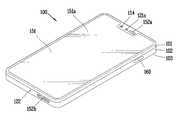
- a display unit 151is disposed on the front of the terminal body to output information. As illustrated, the window 151a of the display unit 151 may be mounted on the front case 101 to form the front surface of the terminal body together with the front case 101.
- electronic componentsmay be mounted on the rear case 102 as well.
- Electronic components that can be mounted on the rear case 102include a removable battery, an identification module, and a memory card.
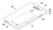
- a rear cover 103 for covering the mounted electronic componentmay be detachably coupled to the rear case 102. Accordingly, when the rear cover 103 is separated from the rear case 102, the electronic components mounted on the rear case 102 are exposed to the outside. Meanwhile, a part of the side surface of the rear case 102 may be implemented to operate as a radiator.
- the rear cover 103when the rear cover 103 is coupled to the rear case 102, a part of the side surface of the rear case 102 may be exposed. In some cases, when the rear case 102 is combined, the rear case 102 may be completely covered by the rear cover 103. Meanwhile, the rear cover 103 may be provided with an opening for exposing the camera 121b or the sound output unit 152b to the outside.
- the mobile terminal 100includes a display unit 151, first and second sound output units 152a and 152b, a proximity sensor 141, an illuminance sensor 142, a light output unit 154, and first and second sound output units.
- Cameras 121a and 121b, first and second operation units 123a and 123b, microphone 122, interface unit 160, and the likemay be provided.
- the display unit 151displays (outputs) information processed by the mobile terminal 100.
- the display unit 151may display execution screen information of an application program driven in the mobile terminal 100, or UI (User Interface) and GUI (Graphic User Interface) information according to such execution screen information. .
- two or more display units 151may exist depending on the implementation type of the mobile terminal 100.
- the mobile terminal 100may have a plurality of display units spaced apart or integrally disposed on one surface, or may be disposed on different surfaces.
- the display unit 151may include a touch sensor that senses a touch on the display unit 151 so as to receive a control command by a touch method. Using this, when a touch is made to the display unit 151, the touch sensor may sense the touch, and the terminal controller 180 may be configured to generate a control command corresponding to the touch based on this.
- Content input by the touch methodmay be letters or numbers, or menu items that can be indicated or designated in various modes.
- the display unit 151may form a touch screen together with a touch sensor, and in this case, the touch screen may function as a user input unit 123 (see FIG. 1A). In some cases, the touch screen may replace at least some functions of the first manipulation unit 123a.
- the first sound output unit 152amay be implemented as a receiver that transmits a call sound to the user's ear, and the second sound output unit 152b is a loud speaker that outputs various alarm sounds or multimedia reproduction sounds. ) Can be implemented.
- the light output unit 154is configured to output light for notifying when an event occurs. Examples of the event include message reception, call signal reception, missed call, alarm, schedule notification, e-mail reception, and information reception through an application. When a user's event confirmation is detected, the terminal controller 180 may control the light output unit 154 to terminate the output of light.
- the first camera 121aprocesses an image frame of a still image or moving picture obtained by an image sensor in a photographing mode or a video call mode.
- the processed image framemay be displayed on the display unit 151 and may be stored in the memory 170.
- the first and second manipulation units 123a and 123bare an example of a user input unit 123 that is manipulated to receive a command for controlling the operation of the mobile terminal 100, and may also be collectively referred to as a manipulating portion. have.
- the first and second operation units 123a and 123bmay be employed in any manner as long as the user operates while receiving a tactile feeling such as touch, push, and scroll.
- the first and second manipulation units 123a and 123bmay also be employed in a manner in which the first and second manipulation units 123a and 123b are operated without a user's tactile feeling through proximity touch, hovering touch, or the like.
- the mobile terminal 100may be provided with a fingerprint recognition sensor for recognizing a user's fingerprint, and the terminal controller 180 may use fingerprint information detected through the fingerprint recognition sensor as an authentication means.
- the fingerprint recognition sensormay be embedded in the display unit 151 or the user input unit 123.
- the microphone 122is configured to receive a user's voice and other sounds.
- the microphone 122may be provided in a plurality of locations and configured to receive stereo sound.
- the interface unit 160becomes a passage through which the mobile terminal 100 can be connected to an external device.
- the interface unit 160is a connection terminal for connection with other devices (eg, earphones, external speakers), a port for short-range communication (eg, an infrared port (IrDA Port), a Bluetooth port (Bluetooth Port), a wireless LAN port, etc.], or at least one of a power supply terminal for supplying power to the mobile terminal 100.
- the interface unit 160may be implemented in the form of a socket for accommodating an external card such as a subscriber identification module (SIM) or a user identity module (UIM), or a memory card for storing information.
- SIMsubscriber identification module
- UIMuser identity module
- a second camera 121bmay be disposed on the rear surface of the terminal body.
- the second camera 121bhas a photographing direction substantially opposite to that of the first camera 121a.
- the second camera 121bmay include a plurality of lenses arranged along at least one line.
- the plurality of lensesmay be arranged in a matrix format.
- Such a cameramay be referred to as an array camera.
- an imagemay be photographed in various ways using a plurality of lenses, and an image of better quality may be obtained.
- the flash 124may be disposed adjacent to the second camera 121b. When a subject is photographed by the second camera 121b, the flash 124 illuminates light toward the subject.
- a second sound output unit 152bmay be additionally disposed on the terminal body.
- the second sound output unit 152bmay implement a stereo function together with the first sound output unit 152a, and may be used to implement a speakerphone mode during a call.
- At least one antenna for wireless communicationmay be provided in the terminal body.
- the antennamay be embedded in the terminal body or may be formed in a case. Meanwhile, a plurality of antennas connected to the 4G wireless communication module 111 and the 5G wireless communication module 112 may be disposed on the side of the terminal.
- the antennamay be formed in a film type and attached to the inner surface of the rear cover 103, or a case including a conductive material may be configured to function as an antenna.
- each of the plurality of antennasis implemented as an array antenna, a plurality of array antennas may be disposed in the mobile terminal.
- mmWavemillimeter wave
- the terminal bodyis provided with a terminal power supply unit 190 (see FIG. 1A) for supplying power to the mobile terminal 100.
- the terminal power supply unit 190may include a battery 191 built in the terminal body or configured to be detachable from the outside of the terminal body.
- the mobile terminalincludes a first power amplifier 210, a second power amplifier 220 and an RFIC 250.
- the mobile terminalmay further include a modem (Modem) 270 and an application processor (AP) 280.
- the modem (Modem, 270) and the application processor (AP, 280)are physically implemented in one chip, and may be implemented in a logical and functional separate form.
- the present inventionis not limited thereto and may be implemented in the form of a physically separated chip according to an application.
- the mobile terminalincludes a plurality of low noise amplifiers (LNAs) 261 to 264 in the receiver.
- LNAslow noise amplifiers
- the first power amplifier 210, the second power amplifier 220, the RFIC 250, and the plurality of low noise amplifiers 261 to 264are all operable in the first communication system and the second communication system.
- the first communication system and the second communication systemmay be a 4G communication system and a 5G communication system, respectively.
- the RFIC 250may be configured as a 4G/5G integrated type, but is not limited thereto and may be configured as a 4G/5G separate type according to an application.
- the RFIC 250is configured as a 4G/5G integrated type, it is advantageous in terms of synchronization between 4G/5G circuits and has an advantage that control signaling by the modem 270 can be simplified.
- the RFIC 250when configured as a 4G/5G separate type, it may be referred to as a 4G RFIC and a 5G RFIC, respectively.
- the RFIC 250when the 5G band and the 4G band have a large difference in bands, such as when the 5G band is configured as a millimeter wave band, the RFIC 250 may be configured as a 4G/5G separate type. In this way, when the RFIC 250 is configured as a 4G/5G separate type, there is an advantage that RF characteristics can be optimized for each of the 4G band and the 5G band.
- the 4G RFIC and the 5G RFICmay be logically and functionally separated, and may be physically implemented on one chip.
- the application processor (AP) 280is configured to control the operation of each component of the mobile terminal. Specifically, the application processor (AP, 280) may control the operation of each component of the mobile terminal through the modem 270.
- the application processormay control the modem 270 through a power management IC (PMIC) for low power operation of the mobile terminal.
- PMICpower management IC
- the modem 270may operate the power circuit of the transmitter and the receiver through the RFIC 250 in a low power mode.
- the application processor (AP) 280may control the RFIC 250 through the modem 270 as follows. For example, if the mobile terminal is in a standby mode (idle mode), at least one of the first and second power amplifiers (110, 120) to operate in a low power mode or off (off) RFIC through the modem 270 250 can be controlled.
- the application processor (AP) 280may control the modem 270 to provide wireless communication capable of low power communication.
- the application processor (AP) 280may control the modem 270 to enable wireless communication with the lowest power. Accordingly, even though the throughput is slightly sacrificed, the application processor (AP) 280 may control the modem 270 and the RFIC 250 to perform short-range communication using only the short-range communication module 113.
- the modem 270may be controlled to select an optimal wireless interface.
- the application processor (AP, 280)may control the modem 270 to receive data through both the 4G base station and the 5G base station according to the remaining battery capacity and available radio resource information.
- the application processor (AP) 280may receive information on the remaining battery capacity from the PMIC and information on available radio resources from the modem 270. Accordingly, if the remaining battery capacity and available radio resources are sufficient, the application processor (AP, 280) may control the modem 270 and the RFIC 250 to receive data through both the 4G base station and the 5G base station.
- the transmitting unit and the receiving unit of each radio systemmay be integrated into one transceiving unit. Accordingly, there is an advantage that a circuit part that integrates two types of system signals can be eliminated from the RF front-end.
- the front end partscan be controlled by the integrated transmission/reception unit, the front end parts can be integrated more efficiently than when the transmission/reception system is separated for each communication system.
- the multiple transmission/reception system as shown in FIG. 2has an advantage of enabling efficient resource allocation since it is possible to control other communication systems as needed, and thereby minimize system delay.
- the first power amplifier 210 and the second power amplifier 220may operate in at least one of the first and second communication systems.
- the first and second power amplifiers 220can operate in both the first and second communication systems.
- one of the first and second power amplifiers 210 and 220may operate in the 4G band and the other may operate in the millimeter wave band. have.
- 4x4 MIMOcan be implemented using four antennas as shown in FIG. 2.
- 4x4 DL MIMOmay be performed through downlink (DL).
- the first to fourth antennas ANT1 to ANT4may be configured to operate in both the 4G band and the 5G band.
- the 5G bandis a millimeter wave (mmWave) band
- the first to fourth antennas ANT1 to ANT4may be configured to operate in any one of the 4G band and the 5G band.
- each of a plurality of separate antennasmay be configured as an array antenna in the millimeter wave band.
- 2x2 MIMOcan be implemented using two antennas connected to the first power amplifier 210 and the second power amplifier 220 among the four antennas.
- 2x2 UL MIMO (2 Tx)may be performed through uplink (UL).
- a transmission signalmay be branched in each of one or two transmission paths, and the branched transmission signal may be connected to a plurality of antennas.
- a switch-type splitter or power divideris built into the RFIC corresponding to the RFIC 250, so that separate parts do not need to be placed outside, thereby improving component mounting performance.
- Ican. Specifically, it is possible to select the transmission unit (TX) of two different communication systems by using a single pole double throw (SPDT) type switch inside the RFIC corresponding to the control unit 250.
- TXtransmission unit
- SPDTsingle pole double throw
- a mobile terminal capable of operating in a plurality of wireless communication systems according to the present inventionmay further include a duplexer 231, a filter 232, and a switch 233.
- the duplexer 231is configured to separate signals in the transmission band and the reception band from each other.
- a signal of a transmission band transmitted through the first and second power amplifiers 210 and 220may be applied to the antennas ANT1 and ANT4 through the first output port of the duplexer 231.
- a signal in the reception band received through the antennas ANT1 and ANT4may be received by the low noise amplifiers 261 and 264 through the second output port of the duplexer 231.
- the filter 232may be configured to pass a signal in a transmission band or a reception band and block signals in the remaining bands.
- the filter 232may include a transmission filter connected to the first output port of the duplexer 231 and a reception filter connected to the second output port of the duplexer 231.
- the filter 232may be configured to pass only a signal of a transmission band or only a signal of a reception band according to the control signal.
- the switch 233is configured to transmit only either a transmission signal or a reception signal.
- the switch 233may be configured in the form of a single pole double throw (SPDT) so as to separate a transmission signal and a reception signal in a time division multiplexing (TDD) scheme.
- the transmission signal and the reception signalare signals of the same frequency band, and accordingly, the duplexer 231 may be implemented in the form of a circulator.
- the switch 233is applicable to a frequency division multiplexing (FDD) scheme.
- the switch 233may be configured in the form of a Double Pole Double Throw (DPDT) so as to connect or block a transmission signal and a reception signal, respectively.
- DPDTDouble Pole Double Throw
- the switch 233is not necessarily required.
- the mobile terminal according to the present inventionmay further include a modem 270 corresponding to the control unit.
- the RFIC 250 and the modem 270may be referred to as a first control unit (or a first processor) and a second control unit (a second processor), respectively.
- the RFIC 250 and the modem 270may be implemented as physically separate circuits.
- the RFIC 250 and the modem 270may be physically logically or functionally divided into one circuit.
- the modem 270may perform control and signal processing for transmission and reception of signals through different communication systems through the RFIC 250.
- the modem 270may be obtained through control information received from a 4G base station and/or a 5G base station.
- the control informationmay be received through a physical downlink control channel (PDCCH), but is not limited thereto.
- PDCCHphysical downlink control channel
- the modem 270may control the RFIC 250 to transmit and/or receive signals through the first communication system and/or the second communication system at a specific time and frequency resource. Accordingly, the RFIC 250 may control transmission circuits including the first and second power amplifiers 210 and 220 to transmit a 4G signal or a 5G signal in a specific time period. Further, the RFIC 250 may control receiving circuits including the first to fourth low noise amplifiers 261 to 264 to receive 4G signals or 5G signals in a specific time period.
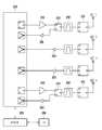
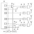
- 3A and 3Bare conceptual diagrams illustrating a structure in which a current is supplied to a transmission/reception antenna and a power amplifier of the transmission/reception antennas in the structure of the wireless communication unit of FIG. 2.
- a wireless communication unit of a mobile terminalmay include four antennas (ANT 1, ANT 2, ANT 3 and ANT 4), of which two antennas (ANT 1, ANT 2) can be used as a transmission/reception antenna.
- the two antennas ANT 1 and ANT 2will be referred to as a first antenna and a second antenna, respectively.
- the first and second antennasmay be formed to have a separation distance greater than or equal to a predetermined distance so as to exclude an influence due to interference between each other.
- the first and second antennasmay be antennas formed to transmit or receive 5G signals.
- the first and second antennasare n41 band (2496-2690 MHz), n77 band and n78 band (3300-4200 MHz and 3300-3800 MHz), n79 band (4400-5000 MHz) according to the 5G NR (New Radio) protocol. ) May be an antenna capable of transmitting or receiving a signal.
- the first and second antennasmay be antennas for transmitting or receiving signals of the same frequency band.
- the wireless communication unit of the mobile terminalmay include a first power amplifier (PA) 210 and a second power amplifier 220 connected to the first antenna and the second antenna, respectively.
- PApower amplifier
- the first power amplifier 210 and the second power amplifier 220may include a power supply unit 330 that supplies current for operation, and a control unit 350 that controls the power supply unit 330. .
- the first and second power amplifiers 210 and 220may be connected to a first antenna and a second antenna, respectively, through a switch 233.
- transmission signals input from the RFIC 250may be amplified into signals having a preset output level, that is, a power level.
- the amplified transmission signalmay be output to a connected antenna. Accordingly, the first antenna or the second antenna may transmit a signal having the preset power level.
- the power supply unit 330may supply current to each of the power amplifiers 210 and 220.
- the power supply unit 330may be a power management IC (PMIC).
- the first and second power amplifiers 210 and 220may amplify a signal input from the RFIC 250 based on the supplied current.
- each power amplifiermay have different output levels of the amplified transmission signals, that is, transmission power levels, according to the amount of supplied current. For example, when the amount of supplied current increases, the transmission signal may be amplified with a signal having a higher power level, and when the amount of supplied current decreases, the transmission signal may be amplified with a signal having a lower power level. . That is, the first and second power amplifiers 210 and 220 may change the power level of the transmission signal according to the amount of current supplied from the power supply unit 330.
- control unit 350may control the current supplied from the power supply unit 330 to each of the power amplifiers 210 and 220.
- the control unit 350may selectively control the power supply unit 330 so that current is supplied to only one of the power amplifiers.
- the control unit 350may be a modem (MODEM, 270) or an application processor (AP, 280).
- the controller 350may be the terminal controller 180 that controls the overall operation of the mobile terminal.
- the control unit 350may select any one power amplifier to be activated. For example, the control unit 350 may select any one power amplifier based on the transmission power headroom of each power amplifier and control the power supply unit 330 so that current is supplied only to the selected one power amplifier. have.
- the transmission power headroomrefers to an output obtained by subtracting the current transmission power from a preset maximum transmission power according to the hardware characteristics of each power amplifier, and may mean a transmission output margin of the corresponding power amplifier. .
- the controller 350may calculate the transmit power headroom of each power amplifier and select any one power amplifier having a large transmit power headroom.
- the power supply unit 330may be controlled so that current is supplied only to the selected power amplifier. In this case, the current supply to other power amplifiers that are not selected may be cut off. Accordingly, one selected power amplifier may be activated, and other power amplifiers not selected may be deactivated. Then, data can be transmitted only through an antenna connected to one of the activated power amplifiers. In this case, since current is continuously supplied to one of the activated power amplifiers, heat is continued, while current supply to the other deactivated power amplifier is cut off, thereby cooling due to a temperature difference with the surrounding air.
- one power amplifier selected according to the difference in the transmission power headroomthat is, one of the first and second power amplifiers 210 and 220 having a larger transmission power headroom value
- a first PAThe other power amplifier having a transmission power headroom value smaller than that of the first PA will be referred to as a second PA.
- the controller 350may activate the second power amplifier based on whether a preset PA change condition is satisfied. Whether the PA change condition is satisfied may be determined according to the temperature of the currently activated power amplifier, that is, the first PA.
- the control unit 350determines that the PA change condition is satisfied and blocks current supply to the first PA.
- the power supply unit 330may be controlled to supply current to the second PA. Then, the first PA may be deactivated, and the second PA, which was in an inactive state, may be changed to an activated state. Then, data may be output through an antenna connected to the second PA.
- the control unit 350may measure the temperature of the first PA and the temperature of the second PA after a predetermined period of time has elapsed. And if the temperature of the first PA (T1) and the temperature of the second PA (T2) are less than a preset second temperature, the controller 350 alternately applies current to the first PA and the second PA at a preset time period.
- the power supply unit 330may be controlled to supply.
- each power amplifiermay be provided with a sensor unit 320 including at least one sensor.
- the sensor unit 320may include a temperature sensor.
- the sensor unit 320may include an output sensor for detecting an output level of a signal currently amplified by each power amplifier.
- at least one of the temperature measured by each temperature sensor and the transmission output size of the power amplifier measured by the output sensormay be input to the control unit 350.
- the preset time periodmay be the same as a data transmission period of the mobile terminal that is time division multiplexed according to a Time Division Duplex (TDD) method.
- the controller 350may change the power amplifier that is activated whenever the data transmission period arrives. Therefore, each time a data transmission period arrives, a transmission signal may be amplified by different power amplifiers, and data may be transmitted through different antennas. That is, whenever the data transmission period is changed, transmission signals may be output through different antenna paths (channels).
- the transmission power parameter for each antenna channelmay be received from the base station whenever the data reception period arrives.
- the transmission power parametermay include information on the strength of a signal received at the base station, and increases or decreases the transmission signal output of the mobile terminal according to the strength of the signal received at the base station. It may include control information for making it.
- the first antenna connected to the first power amplifier 210 and the fourth antenna connected to the second power amplifier 220may be disposed to be spaced apart by a predetermined distance or more to avoid interference between them. More preferably, as shown in FIG. 3B, the first antenna and the fourth antenna are disposed at opposite positions to each other in the vertical direction and/or the left and right directions of the mobile terminal, so that the maximum separation distance between them can be secured. have.
- the power supply unit 330may supply current for driving to the first power amplifier 210 and the second power amplifier 220, respectively.
- the controller 350may receive a temperature value from a temperature sensor provided in the sensor unit 320 of the first power amplifier 210 and the second power amplifier 220.
- an output size of a transmission signalmay be input from an output sensor provided in the sensor unit 320.
- a control signalmay be input to the power supply unit 330.
- the channel environment for each antenna channelmay be different. Accordingly, the strength of the signal received by the base station may be different, and accordingly, the transmission power parameter received from the base station may be different for each antenna channel. Then, the controller 350 may change the transmission power of the antenna to which the current data is transmitted according to the received transmission power parameter. Therefore, when transmission output parameters are received differently for each antenna channel, the sizes of the transmission signal output amplified by each power amplifier may be different from each other.
- the control unit 350may recalculate the transmission power headroom of the two power amplifiers after a predetermined period of time has elapsed.
- values of the calculated transmission power headroommay also vary as the size of the transmission signal output amplified by each power amplifier is different. Accordingly, the control unit 350 may reselect any one power amplifier having a larger transmit power headroom value as the first PA, and may activate only one of the first PA again.
- the control unit 350may reselect any one power amplifier having a larger transmit power headroom value as the first PA, and may activate only one of the first PA again.
- the first PAis activated, the above-described process is performed again, and the second power amplifier is activated according to whether a preset PA change condition is satisfied, and based on the difference between the temperature of the first PA and the temperature of the second PA.
- the first PA and the second PAmay cross each other to be activated.
- the PA change conditionmay further include whether the second PA is usable as well as the first PA temperature condition.
- the control unit 350may calculate the transmission power headroom of the second PA and determine whether the second PA is usable based on the calculated transmission power headroom value.
- the control unit 350may determine that the second PA cannot be used. Then, the control unit 350 may suspend the change of the activated PA to the second PA for a predetermined time. Accordingly, when it is determined that the second PA is in a state that is currently unavailable, the state in which current is supplied to the first PA may be maintained even if the first temperature exceeds a preset first temperature.
- a preset valueeg, 0
- a base station performing communication with a mobile terminalmay determine a channel environment between the mobile terminal and the base station based on data received from the mobile terminal. In addition, based on the determined channel environment, it is possible to request the mobile terminal to change the data transmission method. For example, the base station may detect a loss amount of data received from a mobile terminal using a UL MIMO method and determine a channel environment according to the detected data loss amount. Further, it may be requested to change the data transmission method to a single transmission method according to the determined channel environment. In this case, the base station may transmit a control message for changing a data transmission method, and the control message may include a changed data transmission method and a transmission power parameter corresponding thereto.
- the control unit 350can change the data transmission method from the UL MIMO method in which data is simultaneously transmitted from a plurality of antennas to a single transmission method in which data is transmitted through one antenna.
- the first PAmay be selected and activated based on the transmission power headroom value calculated from each of the power amplifiers, and the transmission output of the activated first PA may be controlled according to the transmission output parameter.
- FIG. 4is a conceptual diagram illustrating an example in which data is exchanged between a mobile terminal and a base station according to an embodiment of the present invention.
- FIG. 4Ashows a transmission/reception schedule of a mobile terminal subjected to time division multiplexing according to a Time Division Duplex (TDD) scheme.
- the mobile terminalmay transmit data to the base station at a signal transmission (TX) time 400 and may receive data from the base station at a signal reception (RX) time 410.
- the signal transmission (TX) time 400 and the signal reception (RX) time 410may be preset according to control data exchanged between the base station of the mobile terminal and the mobile terminal.
- FIG. 4shows an example in which data is exchanged at the signal transmission (TX) time 400 and the signal reception (RX) time 410.
- TX datadata (TX data) may be transmitted from the mobile terminal 430 to the base station 420.
- TX datadata (TX data) may be transmitted.
- the base station 420may determine a channel environment between the base station 420 and the mobile terminal 430 based on the received TX data. For example, the base station 420 may determine a channel environment between the base station 420 and the mobile terminal 430 based on the amount of loss of TX data received during the signal transmission time (TX) 400 (S452).
- TXsignal transmission time
- the base station 420may determine that the current channel environment is suitable for UL MIMO data transmission. . Then, the base station 420 may not generate a control message for changing the data transmission method, and accordingly, the control message may not be transmitted at the signal reception (RX) time 410. In this case, the mobile terminal 430 can maintain the UL MIMO scheme.
- the base station 420may determine that the current channel environment is not suitable for the UL MIMO communication method. Accordingly, the base station 420 may determine that it is necessary to change the data transmission method of the mobile terminal 430 (S452).
- the base station 420may generate a control message requesting the change of the data transmission method (S454).
- the control messagemay include a parameter requesting to change the data transmission method to a single transmission method, and a transmission power parameter requesting an increase in the output of a transmission signal according to the change of the data transmission method.
- control messagemay be transmitted together with data received from the base station 420 at a signal reception (RX) time 410 (S460). Then, the mobile terminal 430 may detect whether the control message is present among the received data (S462). When the control message is received, the data transmission method may be changed to a single transmission method, and the output of the power amplifier may be controlled to increase the output of the transmission signal according to the transmission output parameter (S464).
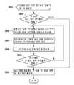
- FIG. 5shows, in the case where the data transmission method is changed from the UL MIMO method to the single transmission method, in the mobile terminal according to the embodiment of the present invention, a power amplifier is selected and activated, and data is transmitted through the selected power amplifier. It is a flow chart showing the operation process.
- the control unit 350may first calculate the transmission power headroom of each power amplifier (S500).
- the transmission power headroommeans the transmission output margin of each power amplifier, and the current transmission power at the maximum transmission power preset according to the hardware characteristics of each power amplifier. It can mean subtracted output.
- the maximum transmission powers preset for each power amplifiermay be stored in the memory 170 in advance.
- the current transmission output of each power amplifiermay be detected from a transmission signal output level detected from an output sensor of each power amplifier.
- the control unit 350may select any one power amplifier as the first PA based on the calculated transmission power headroom values. For example, the control unit 350 may select any one power amplifier having a larger transmit power headroom value among the power amplifiers 210 and 220 as the first PA. This is because a power amplifier having a large transmission power headroom value is a power amplifier whose transmission output is lower than that of the maximum transmission output, and the lower the transmission power is, the less current is supplied. In addition, the less current is supplied, the lower the amount of heat generated.
- the meaning that the value of the transmission power headroom is largemay mean that the channel environment of the antenna connected to the power amplifier is better than that of other antennas.
- the output of the transmission signalthat is, the output of the power amplifier, is determined according to the transmission output parameter received from the base station as described above, and the base station outputs the transmission signal through the transmission output parameter included in the control message as the channel environment is poor. This is because the increase is requested from the mobile terminal.
- the controller 350may control the power supply unit 330 so that current is supplied only to the selected first PA. Then, only the power amplifier selected as the first PA may be activated, and current supply to another power amplifier that is not selected, that is, the second PA, may be cut off and converted into an inactive state (S502).
- the controller 350may amplify a transmission signal through the activated first PA for a preset time and output a transmission signal through an antenna connected to the first PA.
- the transmission power of the first PAmay be controlled according to the transmission power parameter received from the base station.
- the controller 350may measure the temperature of the first PA. And it is possible to determine whether or not the second PA can be used.
- the determination of whether the second PA can be usedmay be made according to the transmission power headroom value of the second PA. That is, as a result of calculating the transmission power headroom value of the second PA, if the calculated value is less than or equal to a preset value, the controller 350 may determine that the second PA is not usable. On the other hand, if the calculated value exceeds a preset value, the controller 350 may determine that the second PA is usable (S504).
- the controller 350may determine whether the PA change condition is satisfied based on the measured temperature of the first PA and the determination result of whether the second PA is usable (S506).
- the PA change conditionmay be satisfied when the second PA is usable while the temperature of the first PA exceeds the first temperature.
- the control unit 350maintains a state in which the first PA is activated for a preset time, that is, a state in which current is supplied only to the first PA, and proceeds to step S504 again to It is possible to measure the temperature of the PA and determine whether the second PA can be used.
- step S506when both of the above conditions are satisfied, the controller 350 may change the activated power amplifier. That is, the control unit 350 may deactivate the first PA by blocking the current supplied to the first PA, and may supply current to the second PA to convert the second PA in the deactivated state into the activated state. (S508).
- a transmission signalmay be amplified through the activated second PA, and a transmission signal may be transmitted through an antenna connected to the second PA.
- the transmission power of the second PAmay be controlled according to the transmission power parameter received from the base station.
- the deactivated first PAmay be cooled due to a temperature difference with ambient air. Accordingly, the temperature of the deactivated first PA may gradually decrease, and the temperature of the second PA changed to the activated state may gradually increase.
- the controller 350may determine whether a preset time has elapsed (S510). In addition, when a preset time has elapsed, the temperature of the currently deactivated first PA and the temperature of the activated second PA may be measured (S512).
- step S512if the difference between the temperature of the first PA and the temperature of the second PA is greater than or equal to a preset second temperature, the controller 350 is in a state in which the first PA is deactivated and the second PA again for a preset time. Can remain active. When a preset time has elapsed, steps S510 and S512 are performed again, and it may be determined whether the difference between the measured temperature of the first PA and the temperature of the second PA is equal to or greater than the second preset temperature.
- the control unit 350alternates between the first PA and the second PA at a preset period of time.
- the power supply unit 330may be controlled so that current is supplied (S516).
- the first PA and the second PAmay be activated by crossing each other at a period of the preset time.
- the preset time periodmay be the same as a data transmission period of the mobile terminal, which is time division multiplexed according to a Time Division Duplex (TDD) method.
- TDDTime Division Duplex
- the PA activated whenever the data transmission period arrivesmay be changed. Therefore, each time a data transmission period arrives, a transmission signal may be amplified by different power amplifiers, and data may be transmitted through different antennas.
- transmission signalsmay be output through different antenna paths (channels).
- transmission output parameters for different antenna channelsmay be received.
- the control unit 350may control the transmission output of the power amplifier of each channel according to the transmission output parameter corresponding to each channel.
- step S516when a predetermined time elapses while the first PA and the second PA are activated by crossing each other in step S516, the controller 350 may proceed to step S500 again. Then, the control unit 350 may recalculate the transmission power headroom values of each power amplifier. Then, the process proceeds to step S502, and the first PA among the power amplifiers may be selected and activated again based on the calculated transmission power headroom values. In this case, the power amplifier not selected as the first PA may be the second PA. In addition, the controller 350 may perform the process of steps S504 to S516 again. The process of FIG. 5 may be repeatedly performed until a request for changing a data transmission scheme in the UL MIMO scheme is received from the base station.
- values of transmission power headroom calculated from each power amplifier in step S500 of FIG. 5may be within a preset tolerance.
- the values of the transmission power headroommay be determined to be the same value.
- the control unit 350may activate the first PA and the second PA by crossing each other for a predetermined period of time and control the transmission output of the power amplifier of each channel according to the transmission output parameter corresponding to each channel. Further, the transmission power headroom of each power amplifier is recalculated according to the controlled transmission output, and any one power amplifier may be selected as the first PA according to the result of the recalculation.
- FIG. 6is a flowchart illustrating an operation process in which a PA is selected according to the calculated transmission power headroom in the mobile terminal according to an embodiment of the present invention in this case.
- the control unit 350may determine whether the calculated transmission power headroom values are the same (S600). For example, when the difference between the calculated transmission power headroom values is within a preset tolerance, the controller 350 may determine that the two values are the same. For example, when the data transmission method is changed to a single transmission method while operating according to the UL MIMO method, values of transmission power headroom calculated from each power amplifier may have the same value.
- the control unit 350alternately supplies current to the first PA and the second PA according to a preset data transmission period for a predetermined time.
- the power supply unit 330can be controlled (S602).
- the first PA and the second PAmay be activated by crossing each other in each data transmission period (S602).
- transmission signalsmay be output through different antenna channels whenever the data transmission period is changed.
- transmission output parameters for different antenna channelsmay be received.
- the control unit 350may control the transmission output of the power amplifier of each channel according to the transmission output parameter corresponding to each channel (S604).
- the transmission power of each power amplifiermay be different from each other.
- control unit 350may recalculate the transmission power headroom of each power amplifier based on the power amplifier transmission output of each channel controlled according to the transmission output parameter corresponding to each channel (S606). Further, it may be determined again whether the recalculated transmission power headroom of each PA is the same (S608).
- step S608if the recalculated transmission power headroom of each PA is the same, the control unit 350 may perform step S604 again in step S602.
- a power amplifier having a larger transmission power headroom valuemay be selected as the first PA and current may be supplied only to the first PA. (S610).
- the controller 350measures the temperature of the first PA and determines whether the second PA is usable by proceeding to step S504 of FIG. 5 after a preset time elapses in the activated state of the first PA. I can.
- step S600determines whether the transmission power headroom values. If the determination result in step S600 is not the same as the transmission power headroom values, the control unit 350 proceeds directly to step S610 and selects a power amplifier having a larger transmission power headroom value as the first PA. have. Then, after a predetermined time elapses, the process proceeds to step S504 of FIG. 5 to measure the temperature of the first PA and determine whether the second PA is usable.
- FIG. 7is an exemplary diagram showing examples of channels through which data is transmitted when one or two PAs among two PAs are switched to each other and activated in a mobile terminal according to an embodiment of the present invention.
- FIG. 7(a)shows an antenna (first channel) connected to the first PA when the first PA and the second PA cross and activate according to the data transmission period, as described in step S516 of FIG. 5, An example in which data is transmitted from a mobile terminal through an antenna (second channel) connected to a second PA is illustrated.
- the first period 701may be divided into a first data transmission period 721 and a first data reception period 711.
- first data transmission period 721if the first PA is activated in the first data transmission period 721, data may be transmitted to the base station through an antenna (first channel: #1) connected to the first PA.
- first channel: #1the antenna connected to the first PA.
- the current supply to the second PAmay be cut off.
- the base stationcan transmit a control message including a transmission power parameter for requesting an increase or decrease in the output of the transmission signal to the mobile terminal in the first data reception period 711.
- the control messagemay not include a transmission power parameter.
- the control unit 350may change the transmission power of the first PA according to the received transmission power parameter.
- the first PAis deactivated by blocking the current supplied to the first PA, and the second PA is activated by supplying current to the second PA. can do.
- datamay be transmitted to the base station through an antenna (second channel: #2) connected to the second PA.
- the base stationmay transmit a control message including a transmission power parameter for requesting an increase or decrease in the output of the transmission signal in the second data reception period 712 to the mobile terminal.
- the controller 350may change the transmission power of the second PA according to the received transmission output parameter.
- this processmay be repeated for each cycle. Therefore, if two PAs are activated by crossing each other, as shown in Fig. 7(a), each time the data transmission period arrives, the transmission signal is amplified by different power amplifiers and data is transmitted through different antennas. Transmission may be transmitted, and transmission output of each power amplifier may be differently controlled based on a transmission output parameter received in response thereto.
- FIG. 7Bshows an example in which data is transmitted only through the first channel #1 as only one first PA is activated, as described in step S502 of FIG. 5.
- the transmission power parameter received from the base stationmay be for the first channel.
- the control unit 350may increase or decrease the transmission power of the first PA according to the transmission power parameter included in the received control message. In this way, when only the first PA is activated, current supply to the second PA may be cut off, and the temperature of the second PA may be lowered due to heat exchange.
- FIG. 7shows an example in which data is transmitted only through the second channel #2 as only one second PA is activated, as described in step S508 of FIG. 5.
- the transmission power parameter received from the base stationmay be for the second channel.
- the control unit 350may increase or decrease the transmission power of the second PA according to the received transmission power parameter.
- current supply to the first PAmay be cut off, and accordingly, the temperature of the first PA may be lowered due to heat exchange.
- FIG. 8is a graph showing changes in the amount of heat generated by the PA when data is transmitted in a single transmission method according to an embodiment of the present invention.
- T1 830may indicate a temperature measured from a first PA
- T2 840may indicate a temperature measured from a second PA.
- the limit temperature Xmay mean a preset first temperature.
- the controller 350may select a first PA and activate only the selected first PA.
- the data transmission methodis changed to a single transmission method as described above, since a signal is transmitted from the base station through one antenna, an increase in transmission signal output may be requested. Accordingly, when only the first PA is activated, more current may be supplied to the first PA. Accordingly, as shown in the first PA operation section 800 of FIG. 8, the temperature T1 of the first PA may be continuously increased. On the other hand, since the current supply to the second PA is cut off and deactivated, the temperature T2 of the second PA may gradually decrease.
- the control unit 350deactivates the first PA by blocking the current supplied to the first PA, and activates the second PA by supplying current to the second PA. Yes (2nd PA operation period 810). Accordingly, as shown in the second PA operation period 810 of FIG. 8, the temperature T2 of the second PA gradually increases, and the temperature T1 of the first PA may gradually decrease.
- the control unit 350may cross and activate the first PA and the second PA for a predetermined time (cross operation period 830).
- the control unit 350may repeat the above process by reselecting the first PA and the second PA according to the transmission output of each controlled power amplifier during the cross operation period 830. . That is, the selected first PA may be activated first (the first PA operation period), and the first PA and the second PA may be activated according to the temperature of the first PA (the second PA operation period). In addition, according to the currently selected temperature T1 of the first PA and the temperature T2 of the second PA, the first PA and the second PA may be activated by crossing each other for a predetermined period of time (cross operation period).
- the present inventionby crossing and activating the power amplifier based on a preset condition, it is possible to prevent the temperature of any one power amplifier from increasing above the preset temperature.
- the present inventionwhen transmitting data according to a single transmission method, by first activating any one power amplifier based on the transmission power headroom calculated from each power amplifier, the power amplifier corresponding to the channel with a better channel environment is preferentially activated. To be able to. Accordingly, the present invention can reduce current consumption while minimizing heat that may be generated locally in the mobile terminal.
- FIG. 9is a conceptual diagram illustrating an operation process of controlling a plurality of PAs in a diagram according to an embodiment of the present invention.
- control unit 350enables data transmission to be performed with only one power amplifier based on the transmit power headroom of each power amplifier (operation with only PA 1 or operation with only PA 2) (S900 , S902).
- control unit 350compares the temperature of PA 1 (T1) and the temperature of PA 2 (T2) (S908). , Based on the comparison result, the first PA and the second PA may be crossed and activated (S910).
- control unit 350may calculate the transmission power headroom of each power amplifier again after a predetermined time elapses (S900).
- data transmissionmay be performed using only one power amplifier according to the calculation result (S902).
- a process from step S904 to step S910may be repeatedly performed.
- the power amplifier of the channel having a better wireless environmentis selected as the first PA by calculating the transmission power headroom of each power amplifier, but this is only an embodiment of the present invention.
- the present inventionis not limited thereto.
- a current sensor or a voltage sensormay be used to detect a power amplifier of a channel having a better wireless environment.
- the sensor unit 320 of each power amplifiermay include a current sensor for detecting the amount of current supplied from the power supply unit 330.
- the current sensor provided in each power amplifiermay measure the amount of current supplied to each power amplifier, and the measured amount of current may be input to the controller 350.
- the control unit 350can detect the size of the current power amplifier transmission output from the amount of current supplied to each power amplifier, and determine the wireless environment of the antenna to which the power amplifier is connected from the detected size of the transmission output. have.
- the lower the transmission powerthat is, the smaller the amount of current flowing into the power amplifier, the better the wireless environment may be determined. Accordingly, a power amplifier having a lower transmit power may be selected as the first PA.
- the amount of current flowing into the power amplifiermay be measured through a voltage sensor instead of a current sensor.
- the controller 350may calculate the amount of current supplied to each power amplifier based on the measured voltage value and the fixed resistance value of each power amplifier. It goes without saying that it is also possible to detect the size of the current power amplifier transmission output from the calculated amount of current, and determine the wireless environment of the antenna to which the power amplifier is connected from the size of the transmission output.
- the transmission power headroom of each power amplifieris calculated, and each power amplifier is alternated according to the calculated result. It has been described as an example of activating or selectively activating one power amplifier, but alternately activating each power amplifier or selectively activating one power amplifier based on the difference in temperature measured from each power amplifier. Of course, it can also be activated with.
- the controller 350may be activated alternately for a predetermined time.
- the process S500 of FIG. 5may be performed to calculate the transmit power headroom of each power amplifier.
- the rest of the process of FIG. 5may be performed.
- the transmission output of each power amplifieris likely to be different from each other. Proceeding to step S500, the transmission power headroom of each power amplifier may be calculated and the rest of the process of FIG. 5 may be performed.
- the present invention described abovecan be implemented as a computer-readable code in a medium on which a program is recorded.
- the computer-readable mediumincludes all types of recording devices storing data that can be read by a computer system. Examples of computer-readable media include HDD (Hard Disk Drive), SSD (Solid State Disk), SDD (Silicon Disk Drive), ROM, RAM, CD-ROM, magnetic tape, floppy disk, optical data storage device, etc. There is also a carrier wave (eg, transmission over the Internet). Also, the computer may include the controller 180 of the terminal. Therefore, the detailed description above should not be construed as restrictive in all respects and should be considered as illustrative. The scope of the present invention should be determined by reasonable interpretation of the appended claims, and all changes within the equivalent scope of the present invention are included in the scope of the present invention.
Landscapes
- Engineering & Computer Science (AREA)
- Computer Networks & Wireless Communication (AREA)
- Signal Processing (AREA)
- Physics & Mathematics (AREA)
- Electromagnetism (AREA)
- Mobile Radio Communication Systems (AREA)
Abstract
Description
Translated fromKorean본 발명은 복수의 PA 및 송신 안테나를 포함하는 이동 단말기에 대한 것으로, 보다 상세하게 UL MIMO(Up Link Multi-Input Multi-Output)를 지원하는 이동 단말기에 관한 것이다.The present invention relates to a mobile terminal including a plurality of PAs and transmission antennas, and more particularly, to a mobile terminal supporting UL MIMO (Up Link Multi-Input Multi-Output).
최근 이동 단말기는 LTE 통신 기술을 이용한 무선 통신 시스템이 상용화되어 다양한 서비스를 제공하고 있다. 또한, 향후에는 5G 통신 기술을 이용한 무선 통신 시스템이 상용화되어 다양한 서비스를 제공할 것으로 기대된다. 한편, LTE 주파수 대역 중 일부를 5G 통신 서비스를 제공하기 위하여 할당될 수 있다.Recently, a wireless communication system using LTE communication technology has been commercialized for mobile terminals, providing various services. In addition, in the future, wireless communication systems using 5G communication technology are expected to be commercialized and provide various services. Meanwhile, some of the LTE frequency bands may be allocated to provide 5G communication services.
상기 5G 네트워크 통신의 경우 데이터 전송률이 높아짐에 따라 하향 링크(Download Link) 뿐만 아니라 상향 링크(Up Link)에 대한 보다 향상된 데이터 전송이 요구되고 있다. 이에 따라 현재 5G 통신이 지원가능한 통상적인 이동 단말기는, 상기 다수의 안테나 중 복수개를 데이터의 수신과 송신에 모두 사용하여 이동 단말기의 데이터 송신 정확도를 향상시키거나 보다 넓은 송신 커버리지를 확보할 수 있도록 하고자 하는 방안이 연구되었다. 그리고 이러한 연구의 결과로서 UL MIMO(Up Link Multi-Input Multi-Output) 방식이 등장하였다. UL MIMO 방식은 복수의 송신 안테나가 동일한 데이터를 전송할 수 있도록 하는 것으로, 보다 효율적으로 데이터를 송신할 수 있다는 잇점이 있다.In the case of the 5G network communication, as the data transmission rate increases, more improved data transmission is required not only for a download link but also an uplink. Accordingly, a typical mobile terminal currently capable of supporting 5G communication uses a plurality of the plurality of antennas for both data reception and transmission to improve the data transmission accuracy of the mobile terminal or to secure wider transmission coverage. The way to do this was studied. And as a result of this study, the UL MIMO (Up Link Multi-Input Multi-Output) method appeared. The UL MIMO scheme allows a plurality of transmission antennas to transmit the same data, and has an advantage in that data can be transmitted more efficiently.
한편 이러한 UL MIMO 방식은 선택적으로 사용될 수 있다. 일 예로 기지국은 이동 단말기와 기지국 사이의 채널 환경이 양호한 경우 UL MIMO 방식에 따라 데이터를 송신함으로써 데이터의 유실율을 크게 낮출 수 있다. 그런데 UL MIMO 방식은 상술한 바와 같이 복수의 송신 안테나가 동시에 데이터를 송신하는 것으로 상기 복수의 안테나 각각의 송신 파워(power)에 의해 결정되는 합 파워(Sum Power)에 따라 이동 단말기의 데이터 송신 파워가 결정될 수 있다. 따라서 채널 환경이 좋지 않은 경우, UL MIMO 방식은 하나의 안테나를 사용하는 통상의 방식보다 더 효율이 저하될 수 있으며, 이에 현재의 이동 단말기는 기지국의 요청에 따라 UL MIMO 방식 또는 하나의 안테나로 데이터를 송신하는 단일 전송(Single Transmission) 방식을 선택적으로 사용하여 데이터를 기지국에 전송할 수 있다.Meanwhile, this UL MIMO scheme can be selectively used. For example, when the channel environment between the mobile terminal and the base station is good, the base station can significantly reduce the data loss rate by transmitting data according to the UL MIMO method. However, in the UL MIMO method, as described above, a plurality of transmission antennas simultaneously transmit data, and the data transmission power of the mobile terminal is determined according to the sum power determined by the transmission power of each of the plurality of antennas. Can be determined. Therefore, if the channel environment is not good, the UL MIMO method may be more efficient than a conventional method using one antenna, and thus, the current mobile terminal may use the UL MIMO method or one antenna at the request of the base station. The data may be transmitted to the base station by selectively using a single transmission method for transmitting a.
그런데 상향 링크에 대한 보다 향상된 데이터 전송 요구에 따라, 이동 단말기에서 데이터를 송신하는 송신 파워의 향상이 요구되고 있다. 이 경우 데이터의 송신 파워가 향상되면 PA에 보다 많은 전류가 공급되어야 하며, 이에 따라 이동 단말기의 PA는 보다 높은 열을 발생시킬 수 있다.However, according to a more advanced data transmission request for an uplink, there is a demand for an improvement in transmission power for transmitting data from a mobile terminal. In this case, if the data transmission power is improved, more current must be supplied to the PA, and accordingly, the PA of the mobile terminal may generate higher heat.
이 경우 UL MIMO 방식에 따르면 복수의 PA에 의해 송신 파워가 분담될 수 있다. 그러나 상기 단일 전송 방식에 따라 데이터를 송신하는 경우 하나의 PA에 의해 송신 파워가 형성되어야 하므로, UL MIMO 방식보다 더 많은 전류가 PA에 공급될 수 있다. 따라서 송신 파워의 향상 시 이동 단말기의 특정 부분, 예를 들어 PA가 배치된 부분에 높은 열이 발생할 수 있으며, 그에 따른 기기 내부의 손상 및 사용자의 상해가 발생할 수 있다는 문제가 있다.In this case, according to the UL MIMO scheme, transmission power may be shared by a plurality of PAs. However, when data is transmitted according to the single transmission scheme, transmission power must be formed by one PA, and thus more current may be supplied to the PA than the UL MIMO scheme. Therefore, when the transmission power is improved, there is a problem that high heat may be generated in a specific part of the mobile terminal, for example, a part in which a PA is disposed, and accordingly, damage inside the device and injury to the user may occur.
본 발명은 전술한 문제 및 다른 문제를 해결하는 것을 목적으로 하는 것으로, 단일 전송 방식으로 데이터를 송신하는 경우에 송신 파워를 향상시키면서도 발열량이 낮은 이동 단말기 및 그 이동 단말기의 제어 방법을 제공하는 것을 그 목적으로 한다. 본 발명의 다른 목적은 사용자가 설정된 회피 영역의 경계를 추종하여 자율 주행이 가능한 로봇 청소기 및 그 로봇 청소기의 제어 방법을 제공하는 것이다.An object of the present invention is to solve the above and other problems, and to provide a mobile terminal with low heat generation while improving transmission power when transmitting data in a single transmission method, and a control method for the mobile terminal. The purpose. Another object of the present invention is to provide a robot cleaner capable of autonomous driving by following a boundary of an avoidance area set by a user, and a control method of the robot cleaner.
상기 또는 다른 목적을 달성하기 위해 본 발명의 일 측면에 따르면, 본 발명의 실시 예에 따른 이동 단말기는. 송수신 겸용으로 사용하는 두 개의 안테나를 포함하는 복수의 안테나와, 상기 두 개의 안테나에 각각 연결되며, 입력되는 전류에 따라 상기 두 개의 안테나에서 송신될 신호를 증폭하여 출력하는 두 개의 PA(Power Amplifier)와, 상기 두 개 PA의 구동을 위한 전류를 공급하는 전원 공급부와, 상기 두 개 PA 각각의 온도를 감지하는 온도 감지부 및, 하나의 안테나를 통해 데이터를 송신하도록 요청하는 기지국의 제어 메시지가 수신되는 경우, 상기 두 개의 PA 각각의 송신 파워 헤드룸(headroom)에 근거하여 제1 PA를 선택 및 선택된 제1 PA에만 전류가 공급되도록 전원 공급부를 제어하고, 상기 제1 PA에 전류가 공급되는 상태에서 상기 제1 PA의 온도에 근거하여 상기 제1 PA에 공급되는 전류를 차단 및 상기 제1 PA와 다른 제2 PA에 전류를 공급하도록 상기 전원 공급부를 제어하는 제어부를 포함하는 것을 특징으로 한다.According to an aspect of the present invention to achieve the above or other objects, a mobile terminal according to an embodiment of the present invention. A plurality of antennas including two antennas used for both transmission and reception, and two power amplifiers (PAs) each connected to the two antennas and amplifying and outputting signals to be transmitted from the two antennas according to an input current Wow, a power supply unit that supplies current for driving the two PAs, a temperature sensing unit that senses the temperature of each of the two PAs, and a control message from the base station requesting to transmit data through one antenna is received. In this case, the first PA is selected based on the transmission power headroom of each of the two PAs, and the power supply is controlled so that current is supplied only to the selected first PA, and current is supplied to the first PA. And a controller configured to control the power supply unit to cut off the current supplied to the first PA based on the temperature of the first PA and to supply current to a second PA different from the first PA.
일 실시 예에 있어서, 상기 제어부는, 상기 제1 PA에 전류가 공급되는 상태에서, 상기 제1 PA에서 감지된 온도가 제1 온도 이상인 경우 상기 제2 PA가 사용가능한지 여부를 상기 제2 PA의 송신 파워 헤드룸에 근거하여 더 검출하고, 상기 감지된 온도가 제1 온도 이상인 상태에서, 상기 제2 PA가 사용 가능한 것으로 판단되면, 상기 제1 PA에 공급되는 전류를 차단 및 상기 제2 PA에 전류를 공급하도록 상기 전원 공급부를 제어하며, 상기 제2 PA가 사용가능한지 여부는, 상기 제2 PA의 송신 파워 헤드룸이 기 설정된 값 이상인지 여부에 따라 결정되는 것을 특징으로 한다.In an embodiment, the control unit determines whether the second PA is usable when the temperature sensed by the first PA is higher than the first temperature in a state where current is supplied to the first PA. Further detection is performed based on the transmission power headroom, and when it is determined that the second PA is usable when the sensed temperature is higher than the first temperature, the current supplied to the first PA is cut off and the second PA is The power supply unit is controlled to supply current, and whether the second PA is usable or not is determined according to whether the transmission power headroom of the second PA is equal to or greater than a preset value.
일 실시 예에 있어서, 상기 제어부는, 상기 제2 PA에 전류가 공급되는 상태에서, 상기 제1 PA와 제2 PA간의 온도 차이를 검출하고, 검출된 온도 차이가 제2 온도 미만인 경우, 상기 두 개의 PA에 교번하여 전류를 공급하도록 상기 전원 공급부를 제어하는 것을 특징으로 한다.In an embodiment, the control unit detects a temperature difference between the first PA and the second PA in a state where current is supplied to the second PA, and when the detected temperature difference is less than the second temperature, the two It is characterized in that the power supply is controlled to supply current to the two PAs alternately.
일 실시 예에 있어서, 상기 제어부는, 상기 두 개의 안테나 모두를 통해 데이터가 송신되는 상태에서, 상기 제어 메시지가 수신되는 경우, 상기 2개 PA의 온도 차이에 근거하여, 송신 파워의 헤드룸에 따라 어느 하나의 PA에만 전류를 공급하거나 또는 상기 두 개의 PA에 교번하여 전류를 공급하도록 상기 전원 공급부를 제어하는 것을 특징으로 한다.In an embodiment, the control unit, when the control message is received in a state in which data is transmitted through both antennas, is based on a temperature difference between the two PAs, according to a headroom of transmission power. It is characterized in that the power supply is controlled to supply current to only one of the PAs or to alternately supply current to the two PAs.
일 실시 예에 있어서, 상기 제어부는, 상기 두 개의 PA에 교번하여 전류가 공급되는 경우, 기 설정된 시간이 경과되면 상기 두 개의 PA 각각의 송신 파워 헤드룸에 근거하여 어느 하나의 PA를 선택 및 선택된 PA에만 전류를 공급하도록 상기 전원 공급부를 제어하는 것을 특징으로 한다.In one embodiment, the controller selects and selects any one PA based on the transmission power headroom of each of the two PAs when a preset time elapses when current is alternately supplied to the two PAs. It characterized in that the power supply is controlled to supply current only to the PA.
일 실시 예에 있어서, 상기 제어부는, 상기 두 개의 PA에 교번하여 전류가 공급되는 경우, TDD(Time Division Duplex) 방식에 따라 시분할 다중화된 상기 이동 단말기의 데이터 송신 주기 마다 서로 다른 PA에 전류를 공급하도록 상기 전원 공급부를 제어하는 것을 특징으로 한다.In one embodiment, the control unit supplies current to different PAs for each data transmission period of the mobile terminal, which is time division multiplexed according to a Time Division Duplex (TDD) method when current is alternately supplied to the two PAs. It characterized in that it controls the power supply to be.
일 실시 예에 있어서, 상기 제1 PA는, 상기 두 개의 PA 중, 송신 파워 헤드룸의 값이 큰 PA임을 특징으로 한다.In one embodiment, the first PA is a PA having a large transmit power headroom value among the two PAs.
일 실시 예에 있어서, 상기 제어 메시지는, 상기 이동 단말기의 두 개 안테나로부터 동시에 데이터들이 송신되는 경우, 상기 기지국이 상기 이동 단말기로부터 수신된 데이터들에 근거하여 판단한 채널 환경에 따라, 상기 기지국으로부터 상기 이동 단말기로 전송되는 것을 특징으로 한다.In one embodiment, the control message is transmitted from the base station according to a channel environment determined by the base station based on data received from the mobile terminal when data is simultaneously transmitted from two antennas of the mobile terminal. It is characterized in that it is transmitted to the mobile terminal.
일 실시 예에 있어서, 상기 제어부는, 각 PA에 기 설정된 최대 송신 파워 헤드룸들 각각으로부터, 각 PA의 현재 송신 출력값을 차감하여, 상기 두 개의 PA 각각의 송신 파워 헤드룸을 산출하는 것을 특징으로 한다.In one embodiment, the control unit calculates the transmission power headroom of each of the two PAs by subtracting the current transmission power value of each PA from each of the maximum transmission power headrooms preset for each PA. do.
일 실시 예에 있어서, 상기 최대 송신 파워 헤드룸들은, 상기 각 PA에 설정된 최대 송신 파워 출력들이며, 상기 각 PA의 현재 송신 출력값은, 상기 기지국의 요청에 포함된 송신 출력 파라미터에 의해 제어된 송신 출력임을 특징으로 한다.In one embodiment, the maximum transmission power headrooms are maximum transmission power outputs set for each PA, and the current transmission power value of each PA is a transmission power controlled by a transmission power parameter included in the request of the base station. It is characterized by
일 실시 예에 있어서, 상기 송수신 겸용으로 사용하는 두 개의 안테나는, 5G NR(New Radio) 프로토콜에 따라 n41 밴드, n77 밴드, n78 밴드 및 n79 밴드 중 어느 한 밴드의 신호를 송신 또는 수신하는 안테나들임을 특징으로 한다.In an embodiment, the two antennas used for both transmission and reception are antennas for transmitting or receiving signals of any one of n41 band, n77 band, n78 band, and n79 band according to the 5G NR (New Radio) protocol. It features.
일 실시 예에 있어서, 상기 제어부는, 모뎀(MODEM), 어플리케이션 프로세서(AP) 또는 상기 이동 단말기의 전반적인 동작을 제어하는 단말기 제어부임을 특징으로 한다.In one embodiment, the control unit is a modem (MODEM), an application processor (AP), or a terminal control unit that controls the overall operation of the mobile terminal.
상기 또는 다른 목적을 달성하기 위해 본 발명의 일 측면에 따르면, 본 발명의 실시 예에 따라 단일 전송 방식으로 데이터 송신 방식이 변경되는 이동 단말기의 제어 방법에 있어서, UL MIMO(Up Link Multi Input Multi Output)를 위해 구비된 복수의 송수신 겸용 채널 각각의 PA(Power Amplifier)들에 대한 송신 파워 헤드룸들을 산출하고 산출된 송신 파워 헤드룸에 근거하여 제1 PA를 선택하는 제1 단계와, 선택된 제1 PA에 전류를 공급하여 상기 제1 PA를 활성화하고, 활성화된 제1 PA를 통해 데이터의 송신을 수행하는 제2 단계와, 상기 제1 PA의 온도 측정 및 상기 제1 PA와 다른 제2 PA의 사용가능 여부를 판단하는 제3 단계와, 상기 제1 PA의 온도 측정 결과 및 상기 제2 PA의 사용 가능 여부 판단 결과에 따라, 상기 제1 PA에 공급되는 전류를 차단하여 제1 PA를 비활성화하고 상기 제2 PA에 전류를 공급하여 제2 PA를 활성화하는 제4 단계와, 상기 활성화된 제2 PA를 통해 데이터의 송신을 수행하는 제5 단계 및, 상기 비활성화된 제1 PA와 활성화된 제2 PA의 온도 차이가 제1 온도 미만인 경우 상기 제1 PA 및 제2 PA에 교번하여 전류를 공급하여, 기 설정된 시간을 주기로 서로 다른 PA를 통해 데이터의 송신을 수행하는 제6 단계를 포함하는 것을 특징으로 한다.In order to achieve the above or other objects, according to an aspect of the present invention, in a control method of a mobile terminal in which a data transmission method is changed to a single transmission method according to an embodiment of the present invention, UL MIMO (Up Link Multi Input Multi Output) A first step of calculating transmission power headrooms for power amplifiers (PAs) of each of a plurality of transmission/reception channels provided for) and selecting a first PA based on the calculated transmission power headroom, and the selected first A second step of activating the first PA by supplying current to a PA, and performing data transmission through the activated first PA, and measuring the temperature of the first PA and the second PA different from the first PA. A third step of determining whether to be usable or not, according to a temperature measurement result of the first PA and a result of determining whether the second PA is usable, inactivating the first PA by blocking the current supplied to the first PA, and A fourth step of activating a second PA by supplying current to the second PA, a fifth step of transmitting data through the activated second PA, and the deactivated first PA and a second activated When the temperature difference of the PA is less than the first temperature, by alternately supplying current to the first PA and the second PA, and a sixth step of performing data transmission through different PAs at a predetermined period of time. To do.
일 실시 예에 있어서, 상기 기 설정된 시간은, TDD(Time Division Duplex) 방식에 따라 시분할 다중화된 상기 이동 단말기의 데이터 송신 주기에 대응하는 시간임을 특징으로 한다.In an embodiment, the preset time is a time corresponding to a data transmission period of the mobile terminal that is time division multiplexed according to a Time Division Duplex (TDD) method.
일 실시 예에 있어서, 상기 제6 단계는, 상기 시분할 다중화된 상기 이동 단말기의 데이터 수신 주기 마다, 서로 다른 PA의 송신 출력 변경을 위한 송신 출력 파라미터를 포함하는 제어 메시지를 상기 기지국으로부터 수신하는 제6-1 단계와, 상기 수신된 송신 출력 파라미터 각각에 따라, 상기 제1 PA 및 제2 PA의 송신 출력을 각각 제어하는 제6-2 단계와, 일정 시간이 경과된 후에, 상기 제1 PA 및 제2 PA의 각각 제어된 송신 출력에 근거하여 각 PA의 송신 파워 헤드룸들을 재산출하는 제6-3 단계 및, 재산출된 송신 파워 헤드룸들에 근거하여 제1 PA를 다시 선택하는 제6-4 단계를 포함하는 것을 특징으로 한다.In an embodiment, in the sixth step, a sixth step of receiving a control message including a transmission power parameter for changing transmission power of different PAs from the base station for each data reception period of the time division multiplexed mobile terminal. Step -1 and step 6-2 of respectively controlling the transmission power of the first PA and the second PA according to each of the received transmission power parameters, and after a predetermined time elapses, the first PA and the
일 실시 예에 있어서, 상기 제1 단계는, 상기 제1 PA와 제2 PA의 온도를 측정 및 측정된 온도의 차이를 산출하는 제1-1 단계 및, 상기 측정된 온도의 차이에 근거하여, 각 PA의 송신 파워 헤드룸들을 바로 산출하거나, 또는 상기 제1 PA 및 제2 PA에 교번하여 전류를 공급하여 기 설정된 시간을 주기로 서로 다른 PA를 통해 데이터의 송신을 수행한 이후에 각 PA의 송신 파워 헤드룸들을 산출하는 제1-2 단계를 포함하는 것을 특징으로 한다.In an embodiment, the first step comprises step 1-1 of measuring the temperature of the first PA and the second PA and calculating a difference between the measured temperature, and based on the difference between the measured temperature, Transmission power headrooms of each PA are calculated immediately, or transmission of each PA is performed after data transmission is performed through different PAs at a predetermined period of time by alternately supplying current to the first and second PAs It characterized in that it comprises a 1-2 step of calculating the power headrooms.
일 실시 예에 있어서, 상기 제2 PA가 사용가능한지 여부는, 상기 제2 PA에 대해 산출된 송신 파워 헤드룸이 기 설정된 값 이상인지 여부에 따라 결정되는 것을 특징으로 한다.In an embodiment, whether the second PA is usable is determined according to whether or not the calculated transmission power headroom for the second PA is equal to or greater than a preset value.
본 발명에 따른 이동 단말기 및 그 제어 방법의 효과에 대해 설명하면 다음과 같다.The effects of the mobile terminal and the control method thereof according to the present invention will be described as follows.
본 발명의 실시 예들 중 적어도 하나에 의하면, 본 발명은 단일 전송 방식에 따라 데이터를 송신 시에, 2개의 PA를 서로 스위칭하여 활성화하여 데이터를 송신함으로써, 이동 단말기에서 국부적으로 발생할 수 있는 열을 최소화하면서도 안정된 통신이 이루어질 수 있도록 하는 효과가 있다.According to at least one of the embodiments of the present invention, the present invention minimizes heat that may occur locally in the mobile terminal by switching and activating two PAs to transmit data when transmitting data according to a single transmission method. In addition, it has the effect of enabling stable communication.
또한 본 발명은 단일 전송 방식에 따라 데이터를 송신 시에, 각 PA로부터 산출된 송신 파워 헤드룸(headroom)에 근거하여, 보다 채널 환경이 양호한 채널에 대응하는 PA가 우선적으로 활성화되도록 함으로써, 이동 단말기에서 국부적으로 발생할 수 있는 열을 최소화하면서도 소모 전류를 저감할 수 있다는 효과가 있다.In addition, the present invention allows a PA corresponding to a channel with a better channel environment to be preferentially activated based on the transmission power headroom calculated from each PA when data is transmitted according to a single transmission method. There is an effect of reducing the current consumption while minimizing the heat that may be generated locally.
도 1a는 본 발명과 관련된 이동 단말기를 설명하기 위한 블록도이다.1A is a block diagram illustrating a mobile terminal related to the present invention.
도 1b 및 1c는 본 발명과 관련된 이동 단말기의 일 예를 서로 다른 방향에서 바라본 예시도이다.1B and 1C are exemplary views as viewed from different directions of an example of a mobile terminal related to the present invention.
도 2는 본 발명의 실시 예에 따라 복수의 무선 통신 시스템에서 동작 가능한 이동 단말기의 무선 통신부의 구성을 도시한 블록도이다.2 is a block diagram illustrating a configuration of a wireless communication unit of a mobile terminal capable of operating in a plurality of wireless communication systems according to an embodiment of the present invention.
도 3a 및 도 3b는 상기 도 2의 무선 통신부 구조에서, 송수신 겸용 안테나들 및 상기 송수신 겸용 안테나들의 PA들에 전류가 공급되는 구조를 도시한 개념도이다.3A and 3B are conceptual diagrams illustrating a structure in which current is supplied to transmission/reception antennas and PAs of the transmission/reception antennas in the structure of the wireless communication unit of FIG. 2.
도 4는 본 발명의 실시 예에 따른 이동 단말기와 기지국간에 데이터들이 교환되는 예를 도시한 개념도이다.4 is a conceptual diagram illustrating an example in which data is exchanged between a mobile terminal and a base station according to an embodiment of the present invention.
도 5는 본 발명의 실시 예에 따른 이동 단말기에서, 단일 전송 방식으로 데이터를 송신할 때에 어느 하나의 PA를 활성화하는 동작 과정을 도시한 흐름도이다.5 is a flowchart illustrating an operation process of activating any one PA when data is transmitted in a single transmission method in a mobile terminal according to an embodiment of the present invention.
도 6은 본 발명의 실시 예에 따른 이동 단말기에서, 산출된 송신 파워 헤드룸에 따라 어느 하나의 PA가 우선적으로 선택되는 동작 과정을 도시한 흐름도이다.6 is a flowchart illustrating an operation process in which a PA is preferentially selected according to a calculated transmission power headroom in a mobile terminal according to an embodiment of the present invention.
도 7은 본 발명의 실시 예에 따른 이동 단말기에서, 2개의 PA 중 어느 하나 또는 2개의 PA를 서로 스위칭하여 활성화되는 경우에 데이터가 송신되는 채널의 예들을 도시한 예시도이다.FIG. 7 is an exemplary diagram showing examples of channels through which data is transmitted when one or two PAs among two PAs are switched to each other and activated in a mobile terminal according to an embodiment of the present invention.
도 8은 본 발명의 실시 예에 따라 단일 전송 방식으로 데이터를 전송하는 경우에, PA의 발열량 변화를 도시한 그래프이다.8 is a graph showing a change in heat generation amount of a PA when data is transmitted in a single transmission method according to an embodiment of the present invention.
도 9는 본 발명의 실시 예에 따라 복수의 PA를 제어하는 동작 과정을 다이어그램으로 도시한 개념도이다.9 is a conceptual diagram illustrating an operation process of controlling a plurality of PAs according to an embodiment of the present invention.
이하, 첨부된 도면을 참조하여 본 명세서에 개시된 실시 예를 상세히 설명하되, 도면 부호에 관계없이 동일하거나 유사한 구성요소는 동일한 참조 번호를 부여하고 이에 대한 중복되는 설명은 생략하기로 한다. 이하의 설명에서 사용되는 구성요소에 대한 접미사 "모듈" 및 "부"는 명세서 작성의 용이함만이 고려되어 부여되거나 혼용되는 것으로서, 그 자체로 서로 구별되는 의미 또는 역할을 갖는 것은 아니다. 또한, 본 명세서에 개시된 실시 예를 설명함에 있어서 관련된 공지 기술에 대한 구체적인 설명이 본 명세서에 개시된 실시 예의 요지를 흐릴 수 있다고 판단되는 경우 그 상세한 설명을 생략한다. 또한, 첨부된 도면은 본 명세서에 개시된 실시 예를 쉽게 이해할 수 있도록 하기 위한 것일 뿐, 첨부된 도면에 의해 본 명세서에 개시된 기술적 사상이 제한되지 않으며, 본 발명의 사상 및 기술 범위에 포함되는 모든 변경, 균등물 내지 대체물을 포함하는 것으로 이해되어야 한다.Hereinafter, exemplary embodiments disclosed in the present specification will be described in detail with reference to the accompanying drawings, but identical or similar elements are denoted by the same reference numerals regardless of reference numerals, and redundant descriptions thereof will be omitted. The suffixes "module" and "unit" for components used in the following description are given or used interchangeably in consideration of only the ease of preparation of the specification, and do not have meanings or roles that are distinguished from each other by themselves. In addition, in describing the embodiments disclosed in the present specification, when it is determined that a detailed description of related known technologies may obscure the subject matter of the embodiments disclosed in the present specification, the detailed description thereof will be omitted. In addition, the accompanying drawings are for easy understanding of the embodiments disclosed in the present specification, and the technical idea disclosed in the present specification is not limited by the accompanying drawings, and all modifications included in the spirit and scope of the present invention It should be understood to include equivalents or substitutes.
제1, 제2 등과 같이 서수를 포함하는 용어는 다양한 구성요소들을 설명하는데 사용될 수 있지만, 상기 구성요소들은 상기 용어들에 의해 한정되지는 않는다. 상기 용어들은 하나의 구성요소를 다른 구성요소로부터 구별하는 목적으로만 사용된다.Terms including ordinal numbers, such as first and second, may be used to describe various elements, but the elements are not limited by the terms. These terms are used only for the purpose of distinguishing one component from another component.
어떤 구성요소가 다른 구성요소에 "연결되어" 있다거나 "접속되어" 있다고 언급된 때에는, 그 다른 구성요소에 직접적으로 연결되어 있거나 또는 접속되어 있을 수도 있지만, 중간에 다른 구성요소가 존재할 수도 있다고 이해되어야 할 것이다. 반면에, 어떤 구성요소가 다른 구성요소에 "직접 연결되어" 있다거나 "직접 접속되어" 있다고 언급된 때에는, 중간에 다른 구성요소가 존재하지 않는 것으로 이해되어야 할 것이다.When a component is referred to as being "connected" or "connected" to another component, it is understood that it may be directly connected or connected to the other component, but other components may exist in the middle. Should be. On the other hand, when a component is referred to as being "directly connected" or "directly connected" to another component, it should be understood that there is no other component in the middle.
단수의 표현은 문맥상 명백하게 다르게 뜻하지 않는 한, 복수의 표현을 포함한다.Singular expressions include plural expressions unless the context clearly indicates otherwise.
본 출원에서, "포함한다" 또는 "가지다" 등의 용어는 명세서상에 기재된 특징, 숫자, 단계, 동작, 구성요소, 부품 또는 이들을 조합한 것이 존재함을 지정하려는 것이지, 하나 또는 그 이상의 다른 특징들이나 숫자, 단계, 동작, 구성요소, 부품 또는 이들을 조합한 것들의 존재 또는 부가 가능성을 미리 배제하지 않는 것으로 이해되어야 한다.In the present application, terms such as "comprises" or "have" are intended to designate the presence of features, numbers, steps, actions, components, parts, or combinations thereof described in the specification, but one or more other features. It is to be understood that the presence or addition of elements or numbers, steps, actions, components, parts, or combinations thereof, does not preclude in advance.
본 명세서에서 설명되는 이동 단말기에는 휴대폰, 스마트 폰(smart phone), 노트북 컴퓨터(laptop computer), 디지털방송용 단말기, PDA(personal digital assistants), PMP(portable multimedia player), 네비게이션, 슬레이트 PC(slate PC), 태블릿 PC(tablet PC), 울트라북(ultrabook), 웨어러블 디바이스(wearable device, 예를 들어, 워치형 단말기 (smartwatch), 글래스형 단말기 (smart glass), HMD(head mounted display)) 등이 포함될 수 있다.Mobile terminals described in this specification include mobile phones, smart phones, laptop computers, digital broadcasting terminals, personal digital assistants (PDAs), portable multimedia players (PMPs), navigation systems, and slate PCs. , Tablet PC (tablet PC), ultrabook (ultrabook), wearable device (wearable device, for example, smartwatch, glass-type terminal (smart glass), HMD (head mounted display)), etc. may be included. have.
그러나 본 명세서에 기재된 실시 예에 따른 구성은 이동 단말기에만 적용 가능한 경우를 제외하면, 디지털 TV, 데스크탑 컴퓨터, 디지털 사이니지 등과 같은 고정 단말기에도 적용될 수도 있음을 본 기술분야의 당업자라면 쉽게 알 수 있을 것이다.However, it will be readily apparent to those skilled in the art that the configuration according to the embodiment described in the present specification may be applied to fixed terminals such as digital TV, desktop computer, digital signage, etc., except when applicable only to mobile terminals. .
도 1a 내지 도 1c를 참조하면, 도 1a는 본 발명과 관련된 이동 단말기를 설명하기 위한 블록도이고, 도 1b 및 1c는 본 발명과 관련된 이동 단말기의 일 예를 서로 다른 방향에서 바라본 개념도이다.1A to 1C, FIG. 1A is a block diagram illustrating a mobile terminal related to the present invention, and FIGS. 1B and 1C are conceptual diagrams of an example of a mobile terminal related to the present invention viewed from different directions.
상기 이동 단말기(100)는 무선 통신부(110), 입력부(120), 센싱부(140), 출력부(150), 인터페이스부(160), 메모리(170), 제어부(180) 및 전원공급부(190) 등을 포함할 수 있다. 도 1a에 도시된 구성요소들은 이동 단말기를 구현하는데 있어서 필수적인 것은 아니어서, 본 명세서 상에서 설명되는 이동 단말기는 위에서 열거된 구성요소들 보다 많거나, 또는 적은 구성요소들을 가질 수 있다.The
보다 구체적으로, 상기 구성요소들 중 무선 통신부(110)는, 이동 단말기(100)와 무선 통신 시스템 사이, 이동 단말기(100)와 다른 이동 단말기(100) 사이, 또는 이동 단말기(100)와 외부서버 사이의 무선 통신을 가능하게 하는 하나 이상의 모듈을 포함할 수 있다. 또한, 상기 무선 통신부(110)는, 이동 단말기(100)를 하나 이상의 네트워크에 연결하는 하나 이상의 모듈을 포함할 수 있다. 여기서, 하나 이상의 네트워크는 예컨대 4G 통신 네트워크 및 5G 통신 네트워크일 수 있다.More specifically, among the components, the
이러한 무선 통신부(110)는, 4G 무선 통신 모듈(111), 5G 무선 통신 모듈(112), 근거리 통신 모듈(113), 위치정보 모듈(114) 중 적어도 하나를 포함할 수 있다.The
4G 무선 통신 모듈(111)은 4G 이동통신 네트워크를 통해 4G 기지국과 4G 신호를 전송 및 수신할 수 있다. 이때, 4G 무선 통신 모듈(111)은 하나 이상의 4G 송신 신호를 4G 기지국으로 전송할 수 있다. 또한, 4G 무선 통신 모듈(111)은 하나 이상의 4G 수신 신호를 4G 기지국으로부터 수신할 수 있다.The 4G
이와 관련하여, 4G 기지국으로 전송되는 복수의 4G 송신 신호에 의해 상향링크(UL: Up-Link) 다중입력 다중출력(MIMO: Multi-Input Multi-Output)이 수행될 수 있다. 또한, 4G 기지국으로부터 수신되는 복수의 4G 수신 신호에 의해 하향링크(DL: Down-Link) 다중입력 다중출력(MIMO: Multi-Input Multi-Output)이 수행될 수 있다.In this regard, an uplink (UL) multi-input multi-output (MIMO) may be performed by a plurality of 4G transmission signals transmitted to the 4G base station. In addition, a downlink (DL) multi-input multiple output (MIMO) may be performed by a plurality of 4G reception signals received from a 4G base station.
5G 무선 통신 모듈(112)은 5G 이동통신 네트워크를 통해 5G 기지국과 5G 신호를 전송 및 수신할 수 있다. 여기서, 4G 기지국과 5G 기지국은 비-스탠드 얼론(NSA: Non-Stand-Alone) 구조일 수 있다. 예컨대, 4G 기지국과 5G 기지국은 셀 내 동일한 위치에 배치되는 공통-배치 구조(co-located structure)일 수 있다. 또는, 5G 기지국은 4G 기지국과 별도의 위치에 스탠드-얼론(SA: Stand-Alone) 구조로 배치될 수 있다.The 5G
5G 무선 통신 모듈(112)은 5G 이동통신 네트워크를 통해 5G 기지국과 5G 신호를 전송 및 수신할 수 있다. 이때, 5G 무선 통신 모듈(112)은 하나 이상의 5G 송신 신호를 5G 기지국으로 전송할 수 있다. 또한, 5G 무선 통신 모듈(112)은 하나 이상의 5G 수신 신호를 5G 기지국으로부터 수신할 수 있다.The 5G
이때, 5G 주파수 대역은 4G 주파수 대역과 동일한 대역을 사용할 수 있고, 이를 LTE 재배치(re-farming)이라고 지칭할 수 있다. 한편, 5G 주파수 대역으로, 6GHz 이하의 대역인 Sub6 대역이 사용될 수 있다.In this case, the 5G frequency band may use the same band as the 4G frequency band, and this may be referred to as LTE re-farming. On the other hand, as the 5G frequency band, the Sub6 band, which is a band below 6GHz, may be used.
반면, 광대역 고속 통신을 수행하기 위해 밀리미터파(mmWave) 대역이 5G 주파수 대역으로 사용될 수 있다. 밀리미터파(mmWave) 대역이 사용되는 경우, 이동 단말기(100)는 기지국과의 통신 커버리지 확장(coverage expansion)을 위해 빔 포밍(beam forming)을 수행할 수 있다.On the other hand, a millimeter wave (mmWave) band may be used as a 5G frequency band to perform broadband high-speed communication. When the millimeter wave (mmWave) band is used, the
한편, 5G 주파수 대역에 관계없이, 5G 통신 시스템에서는 전송 속도 향상을 위해, 더 많은 수의 다중입력 다중출력(MIMO: Multi-Input Multi-Output)을 지원할 수 있다. 이와 관련하여, 5G 기지국으로 전송되는 복수의 5G 송신 신호에 의해 상향링크(UL: Up-Link) MIMO가 수행될 수 있다. 또한, 5G 기지국으로부터 수신되는 복수의 5G 수신 신호에 의해 하향링크(DL: Down-Link) MIMO가 수행될 수 있다.Meanwhile, regardless of the 5G frequency band, in a 5G communication system, a greater number of multiple input multiple outputs (MIMO) may be supported to improve transmission speed. In this regard, uplink (UL) MIMO may be performed by a plurality of 5G transmission signals transmitted to the 5G base station. In addition, downlink (DL) MIMO may be performed by a plurality of 5G reception signals received from the 5G base station.
한편, 무선 통신부(110)는 4G 무선 통신 모듈(111)과 5G 무선 통신 모듈(112)을 통해 4G 기지국 및 5G 기지국과 이중 연결(DC: Dual Connectivity) 상태일 수 있다. 이와 같이, 4G 기지국 및 5G 기지국과의 이중 연결을 EN-DC(EUTRAN NR DC)이라 지칭할 수 있다. 여기서, EUTRAN은 Evolved Universal Telecommunication Radio Access Network로 4G 무선 통신 시스템을 의미하고, NR은 New Radio로 5G 무선 통신 시스템을 의미한다.Meanwhile, the
한편, 4G 기지국과 5G 기지국이 공통-배치 구조(co-located structure)이면, 이종 반송파 집성(inter-CA(Carrier Aggregation)을 통해 스루풋(throughput) 향상이 가능하다. 따라서 4G 기지국 및 5G 기지국과 EN-DC 상태이면, 4G 무선 통신 모듈(111) 및 5G 무선 통신 모듈(112)을 통해 4G 수신 신호와 5G 수신 신호를 동시에 수신할 수 있다.On the other hand, if the 4G base station and the 5G base station have a co-located structure, it is possible to improve throughput through inter-CA (Carrier Aggregation). In the -DC state, a 4G reception signal and a 5G reception signal may be simultaneously received through the 4G
근거리 통신 모듈(113)은 근거리 통신(Short range communication)을 위한 것으로서, 블루투스(Bluetooth™), RFID(Radio Frequency Identification), 적외선 통신(Infrared Data Association; IrDA), UWB(Ultra Wideband), ZigBee, NFC(Near Field Communication), Wi-Fi(Wireless-Fidelity), Wi-Fi Direct, Wireless USB(Wireless Universal Serial Bus) 기술 중 적어도 하나를 이용하여, 근거리 통신을 지원할 수 있다. 이러한, 근거리 통신 모듈(114)은, 근거리 무선 통신망(Wireless Area Networks)을 통해 이동 단말기(100)와 무선 통신 시스템 사이, 이동 단말기(100)와 다른 이동 단말기(100) 사이, 또는 이동 단말기(100)와 다른 이동 단말기(100, 또는 외부서버)가 위치한 네트워크 사이의 무선 통신을 지원할 수 있다. 상기 근거리 무선 통신망은 근거리 무선 개인 통신망(Wireless Personal Area Networks)일 수 있다.The short
한편, 4G 무선 통신 모듈(111) 및 5G 무선 통신 모듈(112)을 이용하여 이동 단말기 간 근거리 통신이 수행될 수 있다. 일 실시 예에서, 기지국을 경유하지 않고 이동 단말기들 간에 D2D (Device-to-Device) 방식에 의해 근거리 통신이 수행될 수 있다.Meanwhile, short-range communication between mobile terminals may be performed using the 4G
한편, 전송 속도 향상 및 통신 시스템 융합(convergence)을 위해, 4G 무선 통신 모듈(111) 및 5G 무선 통신 모듈(112) 중 적어도 하나와 Wi-Fi 통신 모듈(113)을 이용하여 반송파 집성(CA)이 수행될 수 있다. 이와 관련하여, 4G 무선 통신 모듈(111)과 Wi-Fi 통신 모듈(113)을 이용하여 4G + WiFi 반송파 집성(CA)이 수행될 수 있다. 또는, 5G 무선 통신 모듈(112)과 Wi-Fi 통신 모듈(113)을 이용하여 5G + WiFi 반송파 집성(CA)이 수행될 수 있다.Meanwhile, carrier aggregation (CA) using at least one of the 4G
위치정보 모듈(114)은 이동 단말기의 위치(또는 현재 위치)를 획득하기 위한 모듈로서, 그의 대표적인 예로는 GPS(Global Positioning System) 모듈 또는 WiFi(Wireless Fidelity) 모듈이 있다. 예를 들어, 이동 단말기는 GPS모듈을 활용하면, GPS 위성에서 보내는 신호를 이용하여 이동 단말기의 위치를 획득할 수 있다. 다른 예로서, 이동 단말기는 Wi-Fi모듈을 활용하면, Wi-Fi모듈과 무선신호를 송신 또는 수신하는 무선 AP(Wireless Access Point)의 정보에 기반하여, 이동 단말기의 위치를 획득할 수 있다. 필요에 따라서, 위치정보모듈(115)은 치환 또는 부가적으로 이동 단말기의 위치에 관한 데이터를 얻기 위해 무선 통신부(110)의 다른 모듈 중 어느 기능을 수행할 수 있다. 위치정보모듈(115)은 이동 단말기의 위치(또는 현재 위치)를 획득하기 위해 이용되는 모듈로, 이동 단말기의 위치를 직접적으로 계산하거나 획득하는 모듈로 한정되지는 않는다.The
구체적으로, 이동 단말기는 5G 무선 통신 모듈(112)을 활용하면, 5G 무선 통신 모듈 과 무선신호를 송신 또는 수신하는 5G 기지국의 정보에 기반하여 이동 단말기의 위치를 획득할 수 있다. 특히, 밀리미터파(mmWave) 대역의 5G 기지국은 좁은 커버리지를 갖는 소형 셀(small cell)에 배치(deploy)되므로, 이동 단말기의 위치를 획득하는 것이 유리하다.Specifically, if the mobile terminal utilizes the 5G
입력부(120)는, 영상 신호 입력을 위한 카메라(121) 또는 영상 입력부, 오디오 신호 입력을 위한 마이크로폰(microphone, 122), 또는 오디오 입력부, 사용자로부터 정보를 입력받기 위한 사용자 입력부(123, 예를 들어, 터치키(touch key), 푸시키(mechanical key) 등)를 포함할 수 있다. 입력부(120)에서 수집한 음성 데이터나 이미지 데이터는 분석되어 사용자의 제어명령으로 처리될 수 있다.The
센싱부(140)는 이동 단말기 내 정보, 이동 단말기를 둘러싼 주변 환경 정보 및 사용자 정보 중 적어도 하나를 센싱하기 위한 하나 이상의 센서를 포함할 수 있다. 예를 들어, 센싱부(140)는 근접센서(141, proximity sensor), 조도 센서(142, illumination sensor), 터치 센서(touch sensor), 가속도 센서(acceleration sensor), 자기 센서(magnetic sensor), 중력 센서(G-sensor), 자이로스코프 센서(gyroscope sensor), 모션 센서(motion sensor), RGB 센서, 적외선 센서(IR 센서: infrared sensor), 지문인식 센서(finger scan sensor), 초음파 센서(ultrasonic sensor), 광 센서(optical sensor, 예를 들어, 카메라(121 참조)), 마이크로폰(microphone, 122 참조), 배터리 게이지(battery gauge), 환경 센서(예를 들어, 기압계, 습도계, 온도계, 방사능 감지 센서, 열 감지 센서, 가스 감지 센서 등), 화학 센서(예를 들어, 전자 코, 헬스케어 센서, 생체 인식 센서 등) 중 적어도 하나를 포함할 수 있다. 한편, 본 명세서에 개시된 이동 단말기는, 이러한 센서들 중 적어도 둘 이상의 센서에서 센싱되는 정보들을 조합하여 활용할 수 있다.The
출력부(150)는 시각, 청각 또는 촉각 등과 관련된 출력을 발생시키기 위한 것으로, 디스플레이부(151), 음향 출력부(152), 햅팁 모듈(153), 광 출력부(154) 중 적어도 하나를 포함할 수 있다. 디스플레이부(151)는 터치 센서와 상호 레이어 구조를 이루거나 일체형으로 형성됨으로써, 터치 스크린을 구현할 수 있다. 이러한 터치 스크린은, 이동 단말기(100)와 사용자 사이의 입력 인터페이스를 제공하는 사용자 입력부(123)로써 기능함과 동시에, 이동 단말기(100)와 사용자 사이의 출력 인터페이스를 제공할 수 있다.The
인터페이스부(160)는 이동 단말기(100)에 연결되는 다양한 종류의 외부 기기와의 통로 역할을 수행한다. 이러한 인터페이스부(160)는, 유/무선 헤드셋 포트(port), 외부 충전기 포트(port), 유/무선 데이터 포트(port), 메모리 카드(memory card) 포트, 식별 모듈이 구비된 장치를 연결하는 포트(port), 오디오 I/O(Input/Output) 포트(port), 비디오 I/O(Input/Output) 포트(port), 이어폰 포트(port) 중 적어도 하나를 포함할 수 있다. 이동 단말기(100)에서는, 상기 인터페이스부(160)에 외부 기기가 연결되는 것에 대응하여, 연결된 외부 기기와 관련된 적절할 제어를 수행할 수 있다.The
또한, 메모리(170)는 이동 단말기(100)의 다양한 기능을 지원하는 데이터를 저장한다. 메모리(170)는 이동 단말기(100)에서 구동되는 다수의 응용 프로그램(application program 또는 애플리케이션(application)), 이동 단말기(100)의 동작을 위한 데이터들, 명령어들을 저장할 수 있다. 이러한 응용 프로그램 중 적어도 일부는, 무선 통신을 통해 외부 서버로부터 다운로드 될 수 있다. 또한 이러한 응용 프로그램 중 적어도 일부는, 이동 단말기(100)의 기본적인 기능(예를 들어, 전화 착신, 발신 기능, 메시지 수신, 발신 기능)을 위하여 출고 당시부터 이동 단말기(100)상에 존재할 수 있다. 한편, 응용 프로그램은, 메모리(170)에 저장되고, 이동 단말기(100) 상에 설치되어, 제어부(180)에 의하여 상기 이동 단말기의 동작(또는 기능)을 수행하도록 구동될 수 있다.In addition, the
제어부(180)는 상기 응용 프로그램과 관련된 동작 외에도, 통상적으로 이동 단말기(100)의 전반적인 동작을 제어한다. 제어부(180)는 위에서 살펴본 구성요소들을 통해 입력 또는 출력되는 신호, 데이터, 정보 등을 처리하거나 메모리(170)에 저장된 응용 프로그램을 구동함으로써, 사용자에게 적절한 정보 또는 기능을 제공 또는 처리할 수 있다.In addition to the operation related to the application program, the
또한, 제어부(180)는 메모리(170)에 저장된 응용 프로그램을 구동하기 위하여, 도 1a와 함께 살펴본 구성요소들 중 적어도 일부를 제어할 수 있다. 나아가, 제어부(180)는 상기 응용 프로그램의 구동을 위하여, 이동 단말기(100)에 포함된 구성요소들 중 적어도 둘 이상을 서로 조합하여 동작시킬 수 있다.Also, in order to drive an application program stored in the
이하 상기 이동 단말기의 전반적인 동작을 제어하는 제어부(180)를 단말기 제어부(180)라고 하기로 한다.Hereinafter, the
전원공급부(190)는 단말기 제어부(180)의 제어 하에서, 외부의 전원, 내부의 전원을 인가받아 이동 단말기(100)에 포함된 각 구성요소들에 전원을 공급한다. 이러한 전원공급부(190)는 배터리를 포함하며, 상기 배터리는 내장형 배터리 또는 교체 가능한 형태의 배터리가 될 수 있다. 이하 상기 이동 단말기(100)에 포함된 각 구성요소들에 전원을 공급하는 전원공급부(190)를 단말기 전원공급부(190)라고 하기로 한다.The
상기 각 구성요소들 중 적어도 일부는, 이하에서 설명되는 다양한 실시 예들에 따른 이동 단말기의 동작, 제어, 또는 제어방법을 구현하기 위하여 서로 협력하여 동작할 수 있다. 또한, 상기 이동 단말기의 동작, 제어, 또는 제어방법은 상기 메모리(170)에 저장된 적어도 하나의 응용 프로그램의 구동에 의하여 이동 단말기 상에서 구현될 수 있다.At least some of the components may operate in cooperation with each other to implement an operation, control, or control method of a mobile terminal according to various embodiments described below. In addition, the operation, control, or control method of the mobile terminal may be implemented on the mobile terminal by driving at least one application program stored in the
도 1 b 및 1c를 참조하면, 개시된 이동 단말기(100)는 바 형태의 단말기 바디를 구비하고 있다. 다만, 본 발명은 여기에 한정되지 않고 와치 타입, 클립 타입, 글래스 타입 또는 2 이상의 바디들이 상대 이동 가능하게 결합되는 폴더 타입, 플립 타입, 슬라이드 타입, 스윙 타입, 스위블 타입 등 다양한 구조에 적용될 수 있다. 이동 단말기의 특정 유형에 관련될 것이나, 이동 단말기의 특정유형에 관한 설명은 다른 타입의 이동 단말기에 일반적으로 적용될 수 있다. 1B and 1C, the disclosed
여기에서, 단말기 바디는 이동 단말기(100)를 적어도 하나의 집합체로 보아 이를 지칭하는 개념으로 이해될 수 있다.Here, the terminal body may be understood as a concept referring to the
이동 단말기(100)는 외관을 이루는 케이스(예를 들면, 프레임, 하우징, 커버 등)를 포함한다. 도시된 바와 같이, 이동 단말기(100)는 프론트 케이스(101)와 리어 케이스(102)를 포함할 수 있다. 프론트 케이스(101)와 리어 케이스(102)의 결합에 의해 형성되는 내부공간에는 각종 전자부품들이 배치된다. 프론트 케이스(101)와 리어 케이스(102) 사이에는 적어도 하나의 미들 케이스가 추가로 배치될 수 있다.The
단말기 바디의 전면에는 디스플레이부(151)가 배치되어 정보를 출력할 수 있다. 도시된 바와 같이, 디스플레이부(151)의 윈도우(151a)는 프론트 케이스(101)에 장착되어 프론트 케이스(101)와 함께 단말기 바디의 전면을 형성할 수 있다.A
경우에 따라서, 리어 케이스(102)에도 전자부품이 장착될 수 있다. 리어 케이스(102)에 장착 가능한 전자부품은 착탈 가능한 배터리, 식별 모듈, 메모리 카드 등이 있다. 이 경우, 리어 케이스(102)에는 장착된 전자부품을 덮기 위한 후면커버(103)가 착탈 가능하게 결합될 수 있다. 따라서 후면 커버(103)가 리어 케이스(102)로부터 분리되면, 리어 케이스(102)에 장착된 전자부품은 외부로 노출된다. 한편, 리어 케이스(102)의 측면 중 일부가 방사체(radiator)로 동작하도록 구현될 수 있다.In some cases, electronic components may be mounted on the
도시된 바와 같이, 후면커버(103)가 리어 케이스(102)에 결합되면, 리어 케이스(102)의 측면 일부가 노출될 수 있다. 경우에 따라서, 상기 결합시 리어 케이스(102)는 후면커버(103)에 의해 완전히 가려질 수도 있다. 한편, 후면커버(103)에는 카메라(121b)나 음향 출력부(152b)를 외부로 노출시키기 위한 개구부가 구비될 수 있다.As shown, when the
이동 단말기(100)에는 디스플레이부(151), 제1 및 제2 음향 출력부(152a, 152b), 근접 센서(141), 조도 센서(142), 광 출력부(154), 제1 및 제2 카메라(121a, 121b), 제1 및 제2 조작유닛(123a, 123b), 마이크로폰(122), 인터페이스부(160) 등이 구비될 수 있다.The
디스플레이부(151)는 이동 단말기(100)에서 처리되는 정보를 표시(출력)한다. 예를 들어, 디스플레이부(151)는 이동 단말기(100)에서 구동되는 응용 프로그램의 실행화면 정보, 또는 이러한 실행화면 정보에 따른 UI(User Interface), GUI(Graphic User Interface) 정보를 표시할 수 있다.The
또한, 디스플레이부(151)는 이동 단말기(100)의 구현 형태에 따라 2개 이상 존재할 수 있다. 이 경우, 이동 단말기(100)에는 복수의 디스플레이부들이 하나의 면에 이격되거나 일체로 배치될 수 있고, 또한 서로 다른 면에 각각 배치될 수도 있다.In addition, two or
디스플레이부(151)는 터치 방식에 의하여 제어 명령을 입력 받을 수 있도록, 디스플레이부(151)에 대한 터치를 감지하는 터치센서를 포함할 수 있다. 이를 이용하여, 디스플레이부(151)에 대하여 터치가 이루어지면, 터치센서는 상기 터치를 감지하고, 단말기 제어부(180)는 이에 근거하여 상기 터치에 대응하는 제어명령을 발생시키도록 이루어질 수 있다. 터치 방식에 의하여 입력되는 내용은 문자 또는 숫자이거나, 각종 모드에서의 지시 또는 지정 가능한 메뉴항목 등일 수 있다.The
이처럼, 디스플레이부(151)는 터치센서와 함께 터치 스크린을 형성할 수 있으며, 이 경우에 터치 스크린은 사용자 입력부(123, 도 1a 참조)로 기능할 수 있다. 경우에 따라, 터치 스크린은 제1조작유닛(123a)의 적어도 일부 기능을 대체할 수 있다.As such, the
제1음향 출력부(152a)는 통화음을 사용자의 귀에 전달시키는 리시버(receiver)로 구현될 수 있으며, 제2 음향 출력부(152b)는 각종 알람음이나 멀티미디어의 재생음을 출력하는 라우드 스피커(loud speaker)의 형태로 구현될 수 있다.The first
광 출력부(154)는 이벤트의 발생시 이를 알리기 위한 빛을 출력하도록 이루어진다. 상기 이벤트의 예로는 메시지 수신, 호 신호 수신, 부재중 전화, 알람, 일정 알림, 이메일 수신, 애플리케이션을 통한 정보 수신 등을 들 수 있다. 단말기 제어부(180)는 사용자의 이벤트 확인이 감지되면, 빛의 출력이 종료되도록 광 출력부(154)를 제어할 수 있다.The
제1카메라(121a)는 촬영 모드 또는 화상통화 모드에서 이미지 센서에 의해 얻어지는 정지영상 또는 동영상의 화상 프레임을 처리한다. 처리된 화상 프레임은 디스플레이부(151)에 표시될 수 있으며, 메모리(170)에 저장될 수 있다.The
제1 및 제2 조작유닛(123a, 123b)은 이동 단말기(100)의 동작을 제어하기 위한 명령을 입력 받기 위해 조작되는 사용자 입력부(123)의 일 예로서, 조작부(manipulating portion)로도 통칭될 수 있다. 제1 및 제2 조작유닛(123a, 123b)은 터치, 푸시, 스크롤 등 사용자가 촉각적인 느낌을 받으면서 조작하게 되는 방식(tactile manner)이라면 어떤 방식이든 채용될 수 있다. 또한, 제1 및 제2 조작유닛(123a, 123b)은 근접 터치(proximity touch), 호버링(hovering) 터치 등을 통해서 사용자의 촉각적인 느낌이 없이 조작하게 되는 방식으로도 채용될 수 있다.The first and
한편, 이동 단말기(100)에는 사용자의 지문을 인식하는 지문인식센서가 구비될 수 있으며, 단말기 제어부(180)는 지문인식센서를 통하여 감지되는 지문정보를 인증수단으로 이용할 수 있다. 상기 지문인식센서는 디스플레이부(151) 또는 사용자 입력부(123)에 내장될 수 있다.Meanwhile, the
마이크로폰(122)은 사용자의 음성, 기타 소리 등을 입력 받도록 이루어진다. 마이크로폰(122)은 복수의 개소에 구비되어 스테레오 음향을 입력 받도록 구성될 수 있다.The
인터페이스부(160)는 이동 단말기(100)를 외부기기와 연결시킬 수 있는 통로가 된다. 예를 들어, 인터페이스부(160)는 다른 장치(예를 들어, 이어폰, 외장 스피커)와의 연결을 위한 접속단자, 근거리 통신을 위한 포트[예를 들어, 적외선 포트(IrDA Port), 블루투스 포트(Bluetooth Port), 무선 랜 포트(Wireless LAN Port) 등], 또는 이동 단말기(100)에 전원을 공급하기 위한 전원공급단자 중 적어도 하나일 수 있다. 이러한 인터페이스부(160)는 SIM(Subscriber Identification Module) 또는 UIM(User Identity Module), 정보 저장을 위한 메모리 카드 등의 외장형 카드를 수용하는 소켓의 형태로 구현될 수도 있다.The
단말기 바디의 후면에는 제2 카메라(121b)가 배치될 수 있다. 이 경우, 제2 카메라(121b)는 제1 카메라(121a)와 실질적으로 반대되는 촬영 방향을 가지게 된다.A
제2카메라(121b)는 적어도 하나의 라인을 따라 배열되는 복수의 렌즈를 포함할 수 있다. 복수의 렌즈는 행렬(matrix) 형식으로 배열될 수도 있다. 이러한 카메라는, 어레이(array) 카메라로 명명될 수 있다. 제2카메라(121b)가 어레이 카메라로 구성되는 경우, 복수의 렌즈를 이용하여 다양한 방식으로 영상을 촬영할 수 있으며, 보다 나은 품질의 영상을 획득할 수 있다.The
플래시(124)는 제2 카메라(121b)에 인접하게 배치될 수 있다. 플래시(124)는 제2 카메라(121b)로 피사체를 촬영하는 경우에 피사체를 향하여 빛을 비추게 된다.The
단말기 바디에는 제2 음향 출력부(152b)가 추가로 배치될 수 있다. 제2 음향 출력부(152b)는 제1음향 출력부(152a)와 함께 스테레오 기능을 구현할 수 있으며, 통화시 스피커폰 모드의 구현을 위하여 사용될 수도 있다.A second
단말기 바디에는 무선 통신을 위한 적어도 하나의 안테나가 구비될 수 있다. 안테나는 단말기 바디에 내장되거나, 케이스에 형성될 수 있다. 한편, 4G 무선 통신 모듈(111) 및 5G 무선 통신 모듈(112)과 연결되는 복수의 안테나는 단말기 측면에 배치될 수 있다. 또는, 안테나는 필름 타입으로 형성되어 후면 커버(103)의 내측면에 부착될 수도 있고, 도전성 재질을 포함하는 케이스가 안테나로서 기능하도록 구성될 수도 있다.At least one antenna for wireless communication may be provided in the terminal body. The antenna may be embedded in the terminal body or may be formed in a case. Meanwhile, a plurality of antennas connected to the 4G
한편, 단말기 측면에 배치되는 복수의 안테나는 MIMO를 지원하도록 4개 이상으로 구현될 수 있다. 또한, 5G 무선 통신 모듈(112)이 밀리미터파(mmWave) 대역에서 동작하는 경우, 복수의 안테나 각각이 배열 안테나(array antenna)로 구현됨에 따라, 이동 단말기에 복수의 배열 안테나가 배치될 수 있다.Meanwhile, four or more antennas disposed on the side of the terminal may be implemented to support MIMO. In addition, when the 5G
단말기 바디에는 이동 단말기(100)에 전원을 공급하기 위한 단말기 전원공급부(190, 도 1a 참조)가 구비된다. 단말기 전원공급부(190)는 단말기 바디에 내장되거나, 단말기 바디의 외부에서 착탈 가능하게 구성되는 배터리(191)를 포함할 수 있다.The terminal body is provided with a terminal power supply unit 190 (see FIG. 1A) for supplying power to the
이하에서는 본 발명에 따른 다중 송신 시스템 구조 및 이를 구비하는 이동 단말기, 특히 이종 무선 시스템(heterogeneous radio system)에서 전력 증폭기 및 이를 구비하는 이동 단말기와 관련된 실시 예들에 대해 첨부된 도면을 참조하여 살펴보겠다. 본 발명은 본 발명의 정신 및 필수적 특징을 벗어나지 않는 범위에서 다른 특정한 형태로 구체화될 수 있음은 당업자에게 자명하다.Hereinafter, a structure of a multiplex transmission system according to the present invention and a mobile terminal having the same, particularly a power amplifier in a heterogeneous radio system, and embodiments related to a mobile terminal having the same will be described with reference to the accompanying drawings. It is obvious to those skilled in the art that the present invention can be embodied in other specific forms without departing from the spirit and essential features of the present invention.
도 2는 본 발명에 따른 복수의 무선 통신 시스템에서 동작 가능한 이동 단말기의 무선 통신부의 구성을 도시한다. 도 2를 참조하면, 이동 단말기는 제1 전력 증폭기(210), 제2 전력 증폭기(220) 및 RFIC(250)를 포함한다. 또한, 이동 단말기는 모뎀(Modem, 270) 및 어플리케이션 프로세서(AP: Application Processor, 280)를 더 포함할 수 있다. 여기서, 모뎀(Modem, 270)과 어플리케이션 프로세서(AP, 280)와 물리적으로 하나의 chip에 구현되고, 논리적 및 기능적으로 분리된 형태로 구현될 수 있다. 하지만, 이에 한정되지 않고 응용에 따라 물리적으로 분리된 칩(chip)의 형태로 구현될 수도 있다.2 shows the configuration of a wireless communication unit of a mobile terminal capable of operating in a plurality of wireless communication systems according to the present invention. Referring to FIG. 2, the mobile terminal includes a
한편, 이동 단말기는 수신부에서 복수의 저잡음 증폭기(LNA: Low Noise Amplifier, 261 내지 264)를 포함한다. 여기서, 제1 전력 증폭기(210), 제2 전력 증폭기(220), RFIC(250) 및 복수의 저잡음 증폭기(261 내지 264)는 모두 제1 통신 시스템과 제2 통신 시스템에서 동작 가능하다. 이때, 제1 통신 시스템과 제2 통신 시스템은 각각 4G 통신 시스템과 5G 통신 시스템일 수 있다.Meanwhile, the mobile terminal includes a plurality of low noise amplifiers (LNAs) 261 to 264 in the receiver. Here, the
도 2에 도시된 바와 같이, RFIC(250)는 4G/5G 일체형으로 구성될 수 있지만, 이에 한정되지 않고 응용에 따라 4G/5G 분리형으로 구성될 수 있다. RFIC(250)가 4G/5G 일체형으로 구성되는 경우, 4G/5G 회로 간 동기화 (synchronization) 측면에서 유리할 뿐만 아니라, 모뎀(270)에 의한 제어 시그널링이 단순화될 수 있다는 장점이 있다.As shown in FIG. 2, the
한편, RFIC(250)가 4G/5G 분리형으로 구성되는 경우, 4G RFIC 및 5G RFIC로 각각 지칭될 수 있다. 특히, 5G 대역이 밀리미터파 대역으로 구성되는 경우와 같이 5G 대역과 4G 대역의 대역 차이가 큰 경우, RFIC(250)가 4G/5G 분리형으로 구성될 수 있다. 이와 같이, RFIC(250)가 4G/5G 분리형으로 구성되는 경우, 4G 대역과 5G 대역 각각에 대하여 RF 특성을 최적화할 수 있다는 장점이 있다.Meanwhile, when the
한편, RFIC(250)가 4G/5G 분리형으로 구성되는 경우에도 4G RFIC 및 5G RFIC가 논리적 및 기능적으로 분리되고 물리적으로는 하나의 칩(chip)에 구현되는 것도 가능하다.Meanwhile, even when the
한편, 어플리케이션 프로세서(AP, 280)는 이동 단말기의 각 구성부의 동작을 제어하도록 구성한다. 구체적으로, 어플리케이션 프로세서(AP, 280)는 모뎀(270)을 통해 이동 단말기의 각 구성부의 동작을 제어할 수 있다.Meanwhile, the application processor (AP) 280 is configured to control the operation of each component of the mobile terminal. Specifically, the application processor (AP, 280) may control the operation of each component of the mobile terminal through the
예를 들어, 어플리케이션 프로세서(AP, 280)는 이동 단말기의 저전력 동작(low power operation)을 위해 전력 관리 IC(PMIC: Power Management IC)를 통해 모뎀(270)을 제어할 수 있다. 이에 따라, 모뎀(270)은 RFIC(250)를 통해 송신부 및 수신부의 전력 회로를 저전력 모드에서 동작시킬 수 있다.For example, the application processor (AP, 280) may control the
이와 관련하여, 어플리케이션 프로세서(AP, 280)는 이동 단말기가 대기 모드(idle mode)에 있다고 판단되면, 모뎀(270)을 통해 RFIC(250)를 다음과 같이 제어할 수 있다. 예를 들어, 이동 단말기가 대기 모드(idle mode)에 있다면, 제1 및 제2 전력 증폭기(110, 120) 중 적어도 하나가 저전력 모드에서 동작하거나 또는 오프(off)되도록 모뎀(270)을 통해 RFIC(250)를 제어할 수 있다.In this regard, when it is determined that the mobile terminal is in an idle mode, the application processor (AP) 280 may control the
다른 실시 예에 따르면, 어플리케이션 프로세서(AP, 280)는 이동 단말기가 저전력 모드이면, 저전력 통신이 가능한 무선 통신을 제공하도록 모뎀(270)을 제어할 수 있다. 예를 들어, 이동 단말기가 4G 기지국, 5G 기지국 및 액세스 포인트 중 복수의 엔티티와 연결된 경우, 어플리케이션 프로세서(AP, 280)는 가장 저전력으로 무선 통신이 가능하도록 모뎀(270)을 제어할 수 있다. 이에 따라, 스루풋(throughput)을 다소 희생하더라도 어플리케이션 프로세서(AP, 280)는 근거리 통신 모듈(113)만을 이용하여 근거리 통신을 수행하도록 모뎀(270)과 RFIC(250)를 제어할 수 있다.According to another embodiment, when the mobile terminal is in a low power mode, the application processor (AP) 280 may control the
또 다른 실시 예에 따르면, 이동 단말기의 배터리 잔량이 임계치 이상이면, 최적의 무선 인터페이스를 선택하도록 모뎀(270)을 제어할 수 있다. 예를 들어, 어플리케이션 프로세서(AP, 280)는 배터리 잔량과 가용 무선 자원 정보에 따라 4G 기지국 및 5G 기지국 모두를 통해 데이터를 수신할 수 있도록 모뎀(270)을 제어할 수 있다. 이때, 어플리케이션 프로세서(AP, 280)는 배터리 잔량 정보는 PMIC로부터 수신하고, 가용 무선 자원 정보는 모뎀(270)으로부터 수신할 수 있다. 이에 따라 배터리 잔량과 가용 무선 자원이 충분하면, 어플리케이션 프로세서(AP, 280)는 4G 기지국 및 5G 기지국 모두를 통해 데이터를 수신할 수 있도록 모뎀(270)과 RFIC(250)를 제어할 수 있다.According to another embodiment, when the remaining battery capacity of the mobile terminal is equal to or greater than a threshold, the
한편, 도 2의 다중 송수신 시스템(multi-transceiving system)은 각각의 무선 시스템(radio System)의 송신부와 수신부를 하나의 송수신부로 통합할 수 있다. 이에 따라 RF 프론트 엔드(Front-end)에서 두 종류의 시스템 신호를 통합하는 회로부분을 제거할 수 있다는 장점이 있다.Meanwhile, in the multi-transceiving system of FIG. 2, the transmitting unit and the receiving unit of each radio system may be integrated into one transceiving unit. Accordingly, there is an advantage that a circuit part that integrates two types of system signals can be eliminated from the RF front-end.
또한, 프론트 엔드 부품을 통합된 송수신부로 제어 가능하므로, 송수신 시스템이 통신 시스템 별로 분리되었을 경우보다 효율적으로 프론트 엔드 부품이 통합될 수 있다.In addition, since the front end parts can be controlled by the integrated transmission/reception unit, the front end parts can be integrated more efficiently than when the transmission/reception system is separated for each communication system.
또한, 통신 시스템 별로 분리되는 경우, 필요에 따라 다른 통신 시스템을 제어하는 것이 불가능하거나, 이로 인한 시스템 지연(system delay)를 가중시키기 때문에 효율적인 자원 할당이 불가능하다. 반면에, 도 2와 같은 다중 송수신 시스템은, 필요에 따라 다른 통신 시스템을 제어하는 것이 가능하고, 이로 인한 시스템 지연을 최소화할 수 있어 효율적인 자원 할당이 가능한 장점이 있다.In addition, when separated for each communication system, it is impossible to control other communication systems as necessary, or because a system delay is increased due to this, it is impossible to efficiently allocate resources. On the other hand, the multiple transmission/reception system as shown in FIG. 2 has an advantage of enabling efficient resource allocation since it is possible to control other communication systems as needed, and thereby minimize system delay.
한편, 제1 전력 증폭기(210)와 제2 전력 증폭기(220)는 제1 및 제2 통신 시스템 중 적어도 하나에서 동작할 수 있다. 이와 관련하여, 5G 통신 시스템이 4G 대역 또는 Sub6 대역에서 동작하는 경우, 제1 및 제2 전력 증폭기(220)는 제1 및 제2 통신 시스템에서 모두 동작 가능하다.Meanwhile, the
반면에, 5G 통신 시스템이 밀리미터파(mmWave) 대역에서 동작하는 경우, 제1 및 제2 전력 증폭기(210, 220)는 어느 하나는 4G 대역에서 동작하고, 다른 하나는 밀리미터파 대역에서 동작할 수 있다.On the other hand, when the 5G communication system operates in the millimeter wave (mmWave) band, one of the first and
한편, 송수신부와 수신부를 통합하여, 송수신 겸용 안테나를 이용하여 하나의 안테나로 2개의 서로 다른 무선 통신 시스템을 구현할 수 있다. 이때, 도 2와 같이 4개의 안테나를 이용하여 4x4 MIMO 구현이 가능하다. 이때, 하향링크(DL)를 통해 4x4 DL MIMO가 수행될 수 있다.Meanwhile, by integrating the transmitting and receiving unit and the receiving unit, it is possible to implement two different wireless communication systems with a single antenna using a transmitting and receiving antenna. At this time, 4x4 MIMO can be implemented using four antennas as shown in FIG. 2. In this case, 4x4 DL MIMO may be performed through downlink (DL).
한편, 5G 대역이 Sub6 대역이면, 제1 내지 제4 안테나(ANT1 내지 ANT4)는 4G 대역과 5G 대역에서 모두 동작하도록 구성될 수 있다. 반면에, 5G 대역이 밀리미터파(mmWave) 대역이면, 제1 내지 제4 안테나(ANT1 내지 ANT4)는 4G 대역과 5G 대역 중 어느 하나의 대역에서 동작하도록 구성될 수 있다. 이때, 5G 대역이 밀리미터파(mmWave) 대역이면, 별도의 복수 안테나 각각이 밀리미터파 대역에서 배열 안테나로 구성될 수 있다.Meanwhile, if the 5G band is the Sub6 band, the first to fourth antennas ANT1 to ANT4 may be configured to operate in both the 4G band and the 5G band. On the other hand, if the 5G band is a millimeter wave (mmWave) band, the first to fourth antennas ANT1 to ANT4 may be configured to operate in any one of the 4G band and the 5G band. In this case, if the 5G band is a millimeter wave (mmWave) band, each of a plurality of separate antennas may be configured as an array antenna in the millimeter wave band.
한편, 4개의 안테나 중 제1 전력 증폭기(210)와 제2 전력 증폭기(220)에 연결된 2개의 안테나를 이용하여 2x2 MIMO 구현이 가능하다. 이때, 상향링크(UL)를 통해 2x2 UL MIMO (2 Tx)가 수행될 수 있다. 또는, 2x2 UL MIMO에 한정되는 것은 아니고, 1 Tx 또는 4 Tx로 구현 가능하다. 이때, 5G 통신 시스템이 1 Tx로 구현되는 경우, 제1 및 제2 전력 증폭기(210, 220) 중 어느 하나만 5G 대역에서 동작하면 된다. 한편, 5G 통신 시스템이 4Tx로 구현되는 경우, 5G 대역에서 동작하는 추가적인 전력 증폭기가 더 구비될 수 있다. 또는, 하나 또는 두 개의 송신 경로 각각에서 송신 신호를 분기하고, 분기된 송신 신호를 복수의 안테나에 연결할 수 있다.Meanwhile, 2x2 MIMO can be implemented using two antennas connected to the
한편, RFIC(250)에 해당하는 RFIC 내부에 스위치 형태의 분배기(Splitter) 또는 전력 분배기(power divider)가 내장되어 있어, 별도의 부품이 외부에 배치될 필요가 없고 이로 인해 부품 실장성을 개선시킬 수 있다. 구체적으로 제어부(250)에 해당하는 RFIC 내부에 SPDT (Single Pole Double Throw) 형태의 스위치를 사용하여 2개의 서로 다른 통신 시스템의 송신부(TX) 선택이 가능하다.On the other hand, a switch-type splitter or power divider is built into the RFIC corresponding to the
또한 본 발명에 따른 복수의 무선 통신 시스템에서 동작 가능한 이동 단말기는 듀플렉서(duplexer, 231), 필터(232) 및 스위치(233)를 더 포함할 수 있다.In addition, a mobile terminal capable of operating in a plurality of wireless communication systems according to the present invention may further include a
듀플렉서(231)는 송신 대역과 수신 대역의 신호를 상호 분리하도록 구성된다. 이때, 제1 및 제2 전력 증폭기(210, 220)를 통해 송신되는 송신 대역의 신호는 듀플렉서(231)의 제1 출력 포트를 통해 안테나(ANT1, ANT4)에 인가될 수 있다. 반면에, 안테나(ANT1, ANT4)를 통해 수신되는 수신 대역의 신호는 듀플렉서(231)의 제2 출력포트를 통해 저잡음 증폭기(261, 264)로 수신될 수 있다.The
필터(232)는 송신 대역 또는 수신 대역의 신호를 통과(pass)시키고 나머지 대역의 신호는 차단(block)하도록 구성될 수 있다. 이때, 필터(232)는 듀플렉서(231)의 제1 출력 포트에 연결되는 송신 필터와 듀플렉서(231)의 제2 출력포트에 연결되는 수신 필터로 구성될 수 있다. 대안적으로, 필터(232)는 제어 신호에 따라 송신 대역의 신호만을 통과시키거나 또는 수신 대역의 신호만을 통과시키도록 구성될 수 있다.The
스위치(233)는 송신 신호 또는 수신 신호 중 어느 하나만을 전달하도록 구성된다. 본 발명의 일 실시 예에서, 스위치(233)는 시분할 다중화(TDD: Time Division Duplex) 방식으로 송신 신호와 수신 신호를 분리하도록 SPDT (Single Pole Double Throw) 형태로 구성될 수 있다. 이때, 송신 신호와 수신 신호는 동일 주파수 대역의 신호이고, 이에 따라 듀플렉서(231)는 서큘레이터(circulator) 형태로 구현될 수 있다.The
한편, 본 발명의 다른 실시 예에서, 스위치(233)는 주파수 분할 다중화(FDD: Time Division Duplex) 방식에서도 적용 가능하다. 이때, 스위치(233)는 송신 신호와 수신 신호를 각각 연결 또는 차단할 수 있도록 DPDT (Double Pole Double Throw) 형태로 구성될 수 있다. 한편, 듀플렉서(231)에 의해 송신 신호와 수신 신호의 분리가 가능하므로, 스위치(233)가 반드시 필요한 것은 아니다.Meanwhile, in another embodiment of the present invention, the
한편, 본 발명에 따른 이동 단말기는 제어부에 해당하는 모뎀(270)을 더 포함할 수 있다. 이때, RFIC(250)와 모뎀(270)을 각각 제1 제어부 (또는 제1 프로세서)와 제2 제어부(제2 프로세서)로 지칭할 수 있다. 한편, RFIC(250)와 모뎀(270)은 물리적으로 분리된 회로로 구현될 수 있다. 또는, RFIC(250)와 모뎀(270)은 물리적으로 하나의 회로에 논리적 또는 기능적으로 구분될 수 있다.Meanwhile, the mobile terminal according to the present invention may further include a
모뎀(270)은 RFIC(250)를 통해 서로 다른 통신 시스템을 통한 신호의 송신과 수신에 대한 제어 및 신호 처리를 수행할 수 있다. 모뎀(270)은 4G 기지국 및/또는 5G 기지국으로부터 수신된 제어 정보(Control Information)을 통해 획득할 수 있다. 여기서, 제어 정보는 물리 하향링크 제어 채널(PDCCH: Physical Downlink Control CHannel)을 통해 수신될 수 있지만, 이에 한정되는 것은 아니다.The
모뎀(270)은 특정 시간 및 주파수 자원에서 제1 통신 시스템 및/또는 제2 통신 시스템을 통해 신호를 송신 및/또는 수신하도록 RFIC(250)를 제어할 수 있다. 이에 따라, RFIC(250)는 특정 시간 구간에서 4G 신호 또는 5G 신호를 송신하도록 제1 및 제2 전력 증폭기(210, 220)를 포함한 송신 회로들을 제어할 수 있다. 또한, RFIC(250)는 특정 시간 구간에서 4G 신호 또는 5G 신호를 수신하도록 제1 내지 제4 저잡음 증폭기(261 내지 264)를 포함한 수신 회로들을 제어할 수 있다.The
한편, 도 2와 같은 다중 송수신 시스템이 구비된 본 발명에 따른 이동 단말기의 구체적인 동작 및 기능에 대해서 이하에서 검토하기로 한다.Meanwhile, detailed operations and functions of the mobile terminal according to the present invention equipped with the multiple transmission/reception system as shown in FIG. 2 will be described below.
도 3a 및 도 3b는 상기 도 2의 무선 통신부 구조에서, 송수신 겸용 안테나들 및 상기 송수신 겸용 안테나들의 전력 증폭기에 전류가 공급되는 구조를 도시한 개념도이다.3A and 3B are conceptual diagrams illustrating a structure in which a current is supplied to a transmission/reception antenna and a power amplifier of the transmission/reception antennas in the structure of the wireless communication unit of FIG. 2.
먼저 도 3a를 참조하여 살펴보면, 본 발명의 실시 예에 따른 이동 단말기의 무선 통신부는 4개의 안테나(ANT 1, ANT 2, ANT 3 및 ANT 4)를 구비할 수 있으며, 이 중 두 개의 안테나(ANT 1, ANT 2)가 송수신 겸용 안테나로 사용될 수 있다. 이하 상기 두 개의 안테나(ANT 1, ANT 2)를 각각 제1 안테나와 제2 안테나로 칭하기로 한다.First, referring to FIG. 3A, a wireless communication unit of a mobile terminal according to an embodiment of the present invention may include four antennas (
여기서 상기 제1 및 제2 안테나는 서로 간의 간섭으로 인한 영향을 배제할 수 있도록 일정 거리 이상의 이격 거리를 가지도록 형성될 수 있다. 또한 상기 제1 및 제2 안테나는 5G 신호를 송신 또는 수신하도록 형성된 안테나일 수 있다. 이러한 경우 상기 제1 및 제2 안테나는 5G NR(New Radio) 프로토콜에 따라 n41 밴드(2496~2690MHz), n77 밴드 및 n78 밴드 (3300~4200MHz 및 3300~3800 MHz), n79 밴드(4400~5000 MHz)의 신호를 송신 또는 수신할 수 있는 안테나일 수 있다. 그리고 상기 제1 및 제2 안테나는 서로 동일한 주파수 대역의 신호를 송신 또는 수신하는 안테나일 수 있다.Here, the first and second antennas may be formed to have a separation distance greater than or equal to a predetermined distance so as to exclude an influence due to interference between each other. Also, the first and second antennas may be antennas formed to transmit or receive 5G signals. In this case, the first and second antennas are n41 band (2496-2690 MHz), n77 band and n78 band (3300-4200 MHz and 3300-3800 MHz), n79 band (4400-5000 MHz) according to the 5G NR (New Radio) protocol. ) May be an antenna capable of transmitting or receiving a signal. In addition, the first and second antennas may be antennas for transmitting or receiving signals of the same frequency band.
그리고 본 발명의 실시 예에 따른 이동 단말기의 무선 통신부는 상기 제1 안테나와 제2 안테나에 각각 연결되는 제1 전력 증폭기(Power Amplifier, PA, 210)) 및 제2 전력 증폭기(220)를 포함할 수 있다. 그리고 상기 제1 전력 증폭기(210)와 제2 전력 증폭기(220) 각각에 동작을 위한 전류를 공급하는 전원공급부(330), 상기 전원공급부(330)를 제어하는 제어부(350)를 포함할 수 있다.In addition, the wireless communication unit of the mobile terminal according to an embodiment of the present invention may include a first power amplifier (PA) 210 and a
먼저 제1 및 제2 전력 증폭기(210, 220)는 각각 제1 안테나 및 제2 안테나에, 스위치(233)를 통해 연결될 수 있다. 그리고 RFIC(250)로부터 입력된 송신 신호들을 기 설정된 출력 레벨, 즉 파워 레벨을 가지는 신호로 각각 증폭할 수 있다. 그리고 증폭된 송신 신호를 연결된 안테나로 출력할 수 있다. 따라서 상기 제1 안테나 또는 제2 안테나는 상기 기 설정된 파워 레벨을 갖는 신호를 송신할 수 있다.First, the first and
한편 전원공급부(330)는 각 전력 증폭기(210, 220)에 전류를 공급할 수 있다. 상기 전원공급부(330)는 전력 관리 IC (PMIC: Power Management IC)일 수 있다. 그리고 제1 및 제2 전력 증폭기(210, 220)는 공급되는 전류에 근거하여 RFIC(250)로부터 입력되는 신호를 증폭할 수 있다. 이 경우 각 전력 증폭기는 공급되는 전류의 양에 따라 증폭되는 송신 신호의 출력 레벨, 즉 송신 파워 레벨을 서로 다르게 할 수 있다. 일 예로, 공급되는 전류의 양이 증가하는 경우 보다 높은 파워 레벨의 신호로 송신 신호를 증폭할 수 있으며, 공급되는 전류의 양이 감소하는 경우 보다 낮은 파워 레벨의 신호로 송신 신호를 증폭할 수 있다. 즉, 상기 제1 및 제2 전력 증폭기(210, 220)는 전원공급부(330)로부터 공급되는 전류의 양에 따라 송신 신호의 파워 레벨을 변경할 수 있다.Meanwhile, the
한편 제어부(350)는 상기 전원공급부(330)에서 각 전력 증폭기(210, 220)로 공급되는 전류를 제어할 수 있다. 일 예로 제어부(350)는 선택적으로 어느 하나의 전력 증폭기에만 전류가 공급되도록 전원공급부(330)를 제어할 수 있다. 상기 제어부(350)는 모뎀(MODEM, 270) 또는 어플리케이션 프로세서(AP, 280)일 수 있다. 또는 상기 제어부(350)는 이동 단말기의 전반적인 동작을 제어하는 단말기 제어부(180)일 수 있다.Meanwhile, the
제어부(350)는 데이터 송신 방식이 단일 전송 방식으로 변경되는 경우, 활성화될 어느 하나의 전력 증폭기를 선택할 수 있다. 예를 들어 제어부(350)는 각 전력 증폭기의 송신 파워 헤드룸(headroom)에 근거하여 어느 하나의 전력 증폭기를 선택하고 선택된 하나의 전력 증폭기에만 전류가 공급되도록 상기 전원공급부(330)를 제어할 수 있다. 여기서 상기 송신 파워 헤드룸은, 각 전력 증폭기의 하드웨어 특성에 따라 기 설정된 최대 송신 출력에서 현재의 송신 출력을 차감한 출력을 의미하는 것으로, 해당 전력 증폭기의 송신 출력 마진(margin)을 의미할 수 있다.When the data transmission method is changed to a single transmission method, the
제어부(350)는 각 전력 증폭기의 송신 파워 헤드룸을 산출하고, 송신 파워 헤드룸이 큰 어느 하나의 전력 증폭기를 선택할 수 있다. 그리고 선택된 전력 증폭기에만 전류가 공급되도록 전원공급부(330)를 제어할 수 있다. 이 경우 선택되지 않은 다른 전력 증폭기에는 전류 공급이 차단될 수 있다. 이에 따라 선택된 어느 하나의 전력 증폭기는 활성화되고, 선택되지 않은 다른 전력 증폭기는 비활성화될 수 있다. 그러면 활성화된 상기 어느 하나의 전력 증폭기에 연결된 안테나를 통해서만 데이터가 송신될 수 있다. 이 경우 활성화된 상기 어느 하나의 전력 증폭기에는 전류가 계속 공급되므로 발열이 지속되는 반면, 비활성화된 다른 전력 증폭기에는 전류 공급이 차단됨으로써 주변 공기와의 온도 차이로 인한 냉각이 이루어질 수 있다. 이하의 설명에서는 상기 송신 파워 헤드룸의 차이에 따라 선택되는, 즉 상기 제1 및 제2 전력 증폭기들(210, 220) 중 송신 파워 헤드룸의 값이 보다 큰 어느 하나의 전력 증폭기를 제1 PA라고 칭하기로 하고, 상기 제1 PA보다 송신 파워 헤드룸의 값이 작은 다른 하나의 전력 증록기를 제2 PA라고 칭하기로 한다.The
제1 PA가 활성화된 상태에서, 제어부(350)는 기 설정된 PA 변경 조건이 충족되는지 여부에 근거하여 상기 제2 전력 증폭기를 활성화할 수 있다. 여기서 상기 PA 변경 조건의 충족 여부는 현재 활성화된 전력 증폭기, 즉 제1 PA의 온도에 따라 결정될 수 있다.In a state in which the first PA is activated, the
이 경우 현재 상기 제1 PA의 온도가 기 설정된 제1 온도를 초과하면, 제어부(350)는 PA 변경 조건이 충족된 것으로 판단하고 제1 PA로의 전류 공급을 차단할 수 있다. 그리고 제2 PA에 전류를 공급하도록 전원공급부(330)를 제어할 수 있다. 그러면 상기 제1 PA가 비활성화될 수 있으며, 비활성 상태에 있던 제2 PA가 활성화 상태로 변경될 수 있다. 그러면 제2 PA에 연결된 안테나를 통해 데이터가 출력될 수 있다.In this case, when the current temperature of the first PA exceeds a preset first temperature, the
한편 제2 PA가 활성화된 경우, 제어부(350)는 일정 시간이 경과된 이후에 제1 PA의 온도와 제2 PA의 온도를 측정할 수 있다. 그리고 제1 PA의 온도(T1)와 제2 PA의 온도(T2)가 기 설정된 제2 온도 미만인 경우라면, 제어부(350)는 기 설정된 시간 주기로 상기 제1 PA와 제2 PA에 교번하여 전류를 공급하도록 상기 전원공급부(330)를 제어할 수 있다. 이를 위해 각 전력 증폭기에는 적어도 하나의 센서를 포함하는 센서부(320)를 구비할 수 있다. 상기 센서부(320)는 온도 센서를 포함할 수 있다. 또한 상기 센서부(320)는 각 전력 증폭기에서 현재 증폭된 신호의 출력 크기를 감지하기 위한 출력 센서(Power detector)를 포함할 수 있다. 그리고 각 온도 센서에서 계측된 온도 및 출력 센서에서 계측된 전력 증폭기의 송신 출력 크기 중 적어도 하나는 제어부(350)로 입력될 수 있다.Meanwhile, when the second PA is activated, the
상기 기 설정된 시간 주기는, TDD(Time Division Duplex) 방식에 따라 시분할 다중화된 상기 이동 단말기의 데이터 송신 주기와 같을 수 있다. 이 경우 제어부(350)는 데이터 송신 주기가 도래할 때마다 활성화되는 전력 증폭기를 변경할 수 있다. 따라서 데이터 송신 주기가 도래할 때마다 서로 다른 전력 증폭기에서 송신 신호가 증폭될 수 있으며, 서로 다른 안테나를 통해 데이터가 송신될 수 있다. 즉, 데이터 송신 주기가 변경될 때마다 서로 다른 안테나 경로(채널)로 송신 신호가 출력될 수 있다.The preset time period may be the same as a data transmission period of the mobile terminal that is time division multiplexed according to a Time Division Duplex (TDD) method. In this case, the
한편 이처럼 데이터 송신 주기가 도래할 때마다 서로 다른 안테나를 통해 데이터가 송신되는 경우, 데이터 수신 주기가 도래할 때마다 기지국으로부터 각 안테나 채널에 대한 송신 출력 파라미터가 수신될 수 있다. 여기서 상기 송신 출력 파라미터는 기지국에 수신된 신호의 세기에 대한 정보를 포함할 수 있으며, 상기 기지국에 수신된 신호의 세기에 따라 이동 단말기의 송신 신호 출력을 증가(up)시키거나 또는 감소(down)시키기 위한 제어 정보가 포함될 수 있다.Meanwhile, when data is transmitted through different antennas every time the data transmission period arrives, the transmission power parameter for each antenna channel may be received from the base station whenever the data reception period arrives. Here, the transmission power parameter may include information on the strength of a signal received at the base station, and increases or decreases the transmission signal output of the mobile terminal according to the strength of the signal received at the base station. It may include control information for making it.
제1 전력 증폭기(210)에 연결되는 제1 안테나와, 제2 전력 증폭기(220)에 연결되는 제4 안테나는 서로 간에 간섭 현상을 피하기 위해 일정 거리 이상 이격되도록 배치될 수 있다. 보다 바람직하게 도 3b에서 보이고 있는 바와 같이, 제1 안테나와 제4 안테나는 이동 단말기의 상하 방향 및/또는 좌우 방향으로 서로 상반된 위치에 배치되어 서로 간에 최대한의 이격 거리를 확보할 수 있도록 구비될 수 있다. 그리고 전원 공급부(330)는 제1 전력 증폭기(210) 및 제2 전력 증폭기(220)에 각각 구동을 위한 전류를 공급할 수 있다.The first antenna connected to the
한편 제어부(350)는 제1 전력 증폭기(210) 및 제2 전력 증폭기(220)의 센서부(320)에 구비된 온도 센서로부터 온도값을 입력받을 수 있다. 또한 상기 센서부(320)에 구비된 출력 센서로부터 송신 신호의 출력 크기를 입력받을 수 있다. 그리고 송신 신호의 출력 크기에 따라 산출되는 송신 파워 헤드룸 값 및 온도값 중 적어도 하나에 근거하여 제1 전력 증폭기(210) 및 제2 전력 증폭기(220) 중 어느 하나에 전류를 공급하도록 제어하기 위한 제어 신호를 전원 공급부(330)에 입력할 수 있다.Meanwhile, the
한편 상기 도 3b에서 보이고 있는 바와 같이 데이터를 송신하는 안테나의 위치가 서로 다르므로, 각 안테나 채널에 대한 채널 환경이 서로 다를 수 있다. 따라서 기지국에 수신되는 신호의 세기는 서로 다를 수 있으며, 이에 따라 기지국으로부터 수신되는 송신 출력 파라미터는 안테나 채널 별로 서로 다를 수 있다. 그러면 제어부(350)는 수신된 송신 출력 파라미터에 따라 현재 데이터가 송신된 안테나의 송신 출력을 변경할 수 있다. 따라서 안테나 채널 별로 송신 출력 파라미터가 다르게 수신되는 경우 각 전력 증폭기에서 증폭되는 송신 신호 출력의 크기는 서로 달라질 수 있다.Meanwhile, as shown in FIG. 3B, since the locations of antennas for transmitting data are different from each other, the channel environment for each antenna channel may be different. Accordingly, the strength of the signal received by the base station may be different, and accordingly, the transmission power parameter received from the base station may be different for each antenna channel. Then, the
한편 제어부(350)는 상기 제1 PA와 제2 PA에 교번하여 전류가 공급되는 경우, 일정 시간이 경과된 후에 두 개 전력 증폭기의 송신 파워 헤드룸을 다시 산출할 수 있다. 이 경우 각 전력 증폭기에서 증폭되는 송신 신호 출력의 크기가 달라짐에 따라 산출되는 송신 파워 헤드룸의 값들 역시 달라질 수 있다. 이에 따라 제어부(350)는 보다 큰 송신 파워 헤드룸의 값을 가지는 어느 하나의 전력 증폭기를 제1 PA로 다시 선택할 수 있으며, 다시 제1 PA 하나만을 활성화 시킬 수 있다. 그리고 제1 PA가 활성화되면 상술한 과정을 다시 수행하여, 기 설정된 PA 변경 조건의 충족 여부에 따라 상기 제2 전력 증폭기를 활성화 및, 제1 PA의 온도와 제2 PA의 온도의 차이에 근거하여 제1 PA와 제2 PA를 서로 교차하여 활성화시킬 수 있다.Meanwhile, when current is alternately supplied to the first PA and the second PA, the
한편 상기 PA 변경 조건은 상기 제1 PA 온도 조건 뿐만 아니라, 제2 PA가 사용가능한지 여부를 더 포함할 수 있다. 일 예로 제어부(350)는 제2 PA의 송신 파워 헤드룸을 산출하고, 산출된 송신 파워 헤드룸의 값에 근거하여 상기 제2 PA가 사용가능한지 여부를 판단할 수 있다.Meanwhile, the PA change condition may further include whether the second PA is usable as well as the first PA temperature condition. For example, the
이 경우 산출된 송신 파워 헤드룸의 값이 기 설정된 값(예 : 0) 이하인 경우라면 제어부(350)는 제2 PA가 사용할 수 없는 상태라고 판단할 수 있다. 그러면 제어부(350)는 활성화되는 PA를 제2 PA로 변경하는 것을 일정 시간동안 보류할 수 있다. 이에 따라 제2 PA가 현재 사용할 수 없는 상태라고 판단되는 경우, 비록 기 설정된 제1 온도를 초과하는 경우라고 할지라도 제1 PA에 전류가 공급되는 상태가 유지될 수 있다.In this case, if the calculated transmission power headroom value is less than or equal to a preset value (eg, 0), the
한편 본 발명의 실시 예에 따른 이동 단말기와 통신을 수행하는 기지국은, 이동 단말기로부터 수신된 데이터에 근거하여 이동 단말기와 기지국 간의 채널 환경을 판단할 수 있다. 그리고 판단된 채널 환경에 근거하여 이동 단말기에 데이터의 송신 방식을 변경할 것을 요청할 수 있다. 일 예로 기지국은, UL MIMO 방식으로 이동 단말기로부터 수신된 데이터의 손실량을 검출하고, 검출된 데이터 손실량에 따라 채널 환경을 판단할 수 있다. 그리고 판단된 채널 환경에 따라 데이터의 송신 방식을 단일 전송 방식으로 변경할 것을 요청할 수 있다. 이 경우 기지국은 데이터의 송신 방식을 변경하기 위한 제어 메시지를 전송할 수 있으며, 상기 제어 메시지에는 변경된 데이터 송신 방식 및 그에 따른 송신 출력 파라미터가 포함될 수 있다. 그러면 제어부(350)는 기지국으로부터 수신된 제어 메시지에 근거하여, 데이터 송신 방식을, 복수의 안테나에서 동시에 데이터를 전송하는 UL MIMO 방식에서, 하나의 안테나를 통해 데이터를 송신하는 단일 전송 방식으로 변경할 수 있다. 그리고 전력 증폭기들 각각으로부터 산출되는 송신 파워 헤드룸 값에 근거하여 제1 PA를 선택하여 활성화 및, 활성화된 제1 PA의 송신 출력을 상기 송신 출력 파라미터에 따라 제어할 수 있다.Meanwhile, a base station performing communication with a mobile terminal according to an embodiment of the present invention may determine a channel environment between the mobile terminal and the base station based on data received from the mobile terminal. In addition, based on the determined channel environment, it is possible to request the mobile terminal to change the data transmission method. For example, the base station may detect a loss amount of data received from a mobile terminal using a UL MIMO method and determine a channel environment according to the detected data loss amount. Further, it may be requested to change the data transmission method to a single transmission method according to the determined channel environment. In this case, the base station may transmit a control message for changing a data transmission method, and the control message may include a changed data transmission method and a transmission power parameter corresponding thereto. Then, based on the control message received from the base station, the
이와 같이 기지국으로부터 특정 송신 파워 레벨을 요청받는 경우에 기지국과 이동 단말기 사이의 데이터 교환 과정 및, 상기 기지국으로부터 요청된 송신 파워 레벨, 즉 통합 파워 레벨에 근거하여 이동 단말기가 각 전력 증폭기에서 형성되는 송신 파워 레벨을 형성하는 동작 과정을 하기 도 4 및 도 5를 참조하여 보다 자세하게 살펴보기로 한다.In this way, when a specific transmission power level is requested from the base station, the data exchange process between the base station and the mobile terminal, and the transmission power level requested from the base station, that is, the transmission formed by each power amplifier based on the integrated power level. The operation process of forming the power level will be described in more detail with reference to FIGS. 4 and 5 below.
도 4는 본 발명의 실시 예에 따른 이동 단말기와 기지국간에 데이터들이 교환되는 예를 도시한 개념도이다.4 is a conceptual diagram illustrating an example in which data is exchanged between a mobile terminal and a base station according to an embodiment of the present invention.
먼저 도 4의 (a)를 참조하여 살펴보면, 도 4의 (a)는 TDD(Time Division Duplex) 방식에 따라 시분할 다중화된 이동 단말기의 송수신 스케쥴을 도시한 것이다. 도 4의 (a)에 따르면 이동 단말기는 신호 송신(TX) 시간(400)에 기지국에 데이터를 송신할 수 있으며, 신호 수신(RX) 시간(410)에 기지국으로부터 데이터를 수신할 수 있다. 여기서 상기 신호 송신(TX) 시간(400)과 신호 수신(RX) 시간(410)은 이동 단말기의 기지국과 이동 단말기 간에 교환된 제어 데이터에 따라 이 미리 설정될 수 있다. 그리고 호 송신(TX) 시간(400)과 신호 수신(RX) 시간(410) 사이에는 소정의 전환기가 있을 수 있다.First, referring to FIG. 4A, FIG. 4A shows a transmission/reception schedule of a mobile terminal subjected to time division multiplexing according to a Time Division Duplex (TDD) scheme. According to (a) of FIG. 4, the mobile terminal may transmit data to the base station at a signal transmission (TX)
그리고 도 4의 (b)는 상기 신호 송신(TX) 시간(400)과 신호 수신(RX) 시간(410)에 데이터들의 교환이 수행되는 예를 도시한 것이다.In addition, (b) of FIG. 4 shows an example in which data is exchanged at the signal transmission (TX)
먼저 신호 송신 시간(TX)(400)에서는, 이동 단말기(430)로부터 기지국(420)에 데이터(TX 데이터)들이 송신될 수 있다. 이 경우 UN MIMO 방식에 따라 두 개의 안테나를 통해 동시에 데이터가 송신되는 경우라면 동일한 송신 데이터(TX data)가 2개씩 송신될 수 있다.First, at the signal transmission time (TX) 400, data (TX data) may be transmitted from the
그러면 기지국(420)은 수신된 TX 데이터들에 근거하여, 기지국(420)과 이동 단말기(430) 사이의 채널 환경을 판단할 수 있다. 일 예로 기지국(420)은 신호 송신 시간(TX)(400) 동안 수신된 TX 데이터들의 손실량에 근거하여 기지국(420)과 이동 단말기(430) 사이의 채널 환경을 판단할 수도 있다(S452).Then, the
상기 S452 단계에서 기지국(420)이 채널 환경을 판단한 결과 기 설정된 수준 이상의 데이터 손실이 발생하지 않은 경우라면 기지국(420)은 현재의 채널 환경이, UL MIMO 방식의 데이터 송신에 적합한 것으로 판단할 수 있다. 그러면 기지국(420)은 데이터 송신 방식 변경을 위한 제어 메시지를 생성하지 않을 수 있으며, 이에 따라 신호 수신(RX) 시간(410)에 상기 제어 메시지가 전송되지 않을 수 있다. 이 경우 이동 단말기(430)는 UL MIMO 방식을 유지할 수 있다.If, as a result of the
반면 상기 S452 단계에서 기 설정된 수준 이상의 데이터 손실이 발생한 경우, 기지국(420)은 현재의 채널 환경이 UL MIMO 통신 방식에 적합하지 않은 것으로 판단할 수 있다. 이에 따라 기지국(420)은 이동 단말기(430)의 데이터 송신 방식 변경이 필요한 것으로 판단할 수 있다(S452).On the other hand, when a data loss of more than a preset level occurs in step S452, the
상기 S452 단계의 판단 결과, 데이터 송신 방식의 변경이 필요한 것으로 판단되는 경우, 기지국(420)은 데이터 송신 방식의 변경을 요청하는 제어 메시지를 생성할 수 있다(S454). 이 경우 상기 제어 메시지는 데이터 송신 방식을 단일 전송 방식으로 변경할 것을 요청하는 파라미터와, 데이터 전송 방식의 변경에 따른 송신 신호의 출력 증가를 요청하는 송신 출력 파라미터를 포함할 수 있다.If, as a result of the determination in step S452, it is determined that the change of the data transmission method is necessary, the
한편 상기 제어 메시지는 신호 수신(RX) 시간(410)에 상기 기지국(420)으로부터 수신되는 데이터들과 함께 전송될 수 있다(S460). 그러면 이동 단말기(430)는 수신된 데이터들 중에 상기 제어 메시지가 있는지 여부를 검출할 수 있다(S462). 그리고 제어 메시지가 수신된 경우 데이터 송신 방식을 단일 전송 방식으로 변경하고, 송신 출력 파라미터에 따라 송신 신호의 출력이 증가하도록 전력 증폭기의 출력을 제어할 수 있다(S464).Meanwhile, the control message may be transmitted together with data received from the
도 5는 이처럼 데이터 송신 방식이 UL MIMO 방식에서 단일 전송 방식으로 변경되는 경우에 본 발명의 실시 예에 따른 이동 단말기에서, 어느 하나의 전력 증폭기를 선택하여 활성화 및 선택된 전력 증폭기를 통해 데이터를 전송하는 동작 과정을 도시한 흐름도이다.5 shows, in the case where the data transmission method is changed from the UL MIMO method to the single transmission method, in the mobile terminal according to the embodiment of the present invention, a power amplifier is selected and activated, and data is transmitted through the selected power amplifier. It is a flow chart showing the operation process.
도 5를 참조하여 살펴보면, 단일 전송 방식으로 데이터 송신 방식이 변경되는 경우, 제어부(350)는 먼저 각 전력 증폭기의 송신 파워 헤드룸을 산출할 수 있다(S500). 여기서 상기 송신 파워 헤드룸은, 여기서 상기 송신 파워 헤드룸은, 각 전력 증폭기의 송신 출력 마진(margin)을 의미하는 것으로, 각 전력 증폭기의 하드웨어 특성에 따라 기 설정된 최대 송신 출력에서 현재의 송신 출력을 차감한 출력을 의미할 수 있다. 이를 위해 메모리(170)에는 상기 각 전력 증폭기에 대해 기 설정된 최대 송신 출력들이 미리 저장될 수 있다. 그리고 각 전력 증폭기의 현재 송신 출력은 각 전력 증폭기의 출력 센서로부터 검출되는 송신 신호 출력 크기로부터 검출될 수 있다.Referring to FIG. 5, when the data transmission method is changed to a single transmission method, the
한편 S500 단계에서 각 전력 증폭기의 송신 파워 헤드룸들이 산출되면, 제어부(350)는 산출된 송신 파워 헤드룸의 값들에 근거하여 어느 하나의 전력 증폭기를 제1 PA로 선택할 수 있다. 일 예로 제어부(350)는, 전력 증폭기들(210, 220) 중 보다 큰 송신 파워 헤드룸 값을 가지는 어느 하나의 전력 증폭기를 제1 PA로 선택할 수 있다. 송신 파워 헤드룸의 값이 큰 전력 증폭기는, 송신 출력이 최대 송신 출력에 비하여 낮은 전력 증폭기이며, 송신 출력이 낮을수록 공급되는 전류가 적기 때문이다. 또한 공급되는 전류가 적을수록 발열량이 낮기 때문이다.Meanwhile, when the transmission power headrooms of each power amplifier are calculated in step S500, the
여기서 송신 파워 헤드룸의 값이 크다는 의미는, 그 전력 증폭기에 연결된 안테나의 채널 환경이 다른 안테나의 채널 환경보다 양호하다는 의미일 수도 있다. 이는 송신 신호의 출력, 즉 전력 증폭기의 출력은, 상술한 바와 같이 기지국으로부터 수신되는 송신 출력 파라미터에 따라 결정되며, 기지국은 채널 환경이 열악할수록 제어 메시지에 포함된 송신 출력 파라미터를 통해 송신 신호의 출력 증가를 이동 단말기에 요청하기 때문이다.Here, the meaning that the value of the transmission power headroom is large may mean that the channel environment of the antenna connected to the power amplifier is better than that of other antennas. This means that the output of the transmission signal, that is, the output of the power amplifier, is determined according to the transmission output parameter received from the base station as described above, and the base station outputs the transmission signal through the transmission output parameter included in the control message as the channel environment is poor. This is because the increase is requested from the mobile terminal.
한편 어느 하나의 전력 증폭기가 제1 PA로 선택되면, 제어부(350)는 선택된 제1 PA에만 전류가 공급되도록 전원공급부(330)를 제어할 수 있다. 그러면 제1 PA로 선택된 전력 증폭기만 활성화될 수 있으며, 선택되지 않은 다른 전력 증폭기, 즉 제2 PA에는 전류 공급이 차단되어 비활성화 상태로 전환될 수 있다(S502).Meanwhile, when any one power amplifier is selected as the first PA, the
상기 S502 단계에서 제1 PA가 활성화되면, 제어부(350)는 기 설정된 시간동안 활성화된 제1 PA를 통해 송신 신호를 증폭하고, 제1 PA에 연결된 안테나를 통해 송신 신호를 출력할 수 있다. 이 경우 기지국으로부터 수신된 송신 출력 파라미터에 따라 제1 PA의 송신 출력이 제어될 수 있다.When the first PA is activated in step S502, the
한편 기 설정된 시간이 경과되면 제어부(350)는 제1 PA의 온도를 측정할 수 있다. 그리고 제2 PA의 사용이 가능한지 여부를 판단할 수 있다. 여기서 상기 제2 PA의 사용이 가능한지 여부의 판단은 상기 제2 PA의 송신 파워 헤드룸 값에 따라 이루어질 수 있다. 즉, 제2 PA의 송신 파워 헤드룸 값을 산출한 결과, 산출된 값이 기 설정된 값 이하인 경우라면, 제어부(350)는 제2 PA가 사용가능하지 않은 상태라고 판단할 수 있다. 반면 산출된 값이 기 설정된 값을 초과하는 경우라면, 제어부(350)는 제2 PA가 사용가능한 것으로 판단할 수 있다(S504).Meanwhile, when a preset time elapses, the
그리고 제어부(350)는 측정된 제1 PA의 온도와 제2 PA의 사용가능 여부 판단 결과에 근거하여 PA 변경 조건이 충족되었는지 여부를 판단할 수 있다(S506). 예를 들어 상기 PA 변경 조건은 제1 PA의 온도가 제1 온도를 초과하는 상태에서, 제2 PA가 사용 가능한 경우에 충족될 수 있다. 이 경우 제어부(350)는 위 두 가지 조건을 모두 만족하지 않는 경우 기 설정된 시간동안 제1 PA가 활성화된 상태, 즉 제1 PA에만 전류가 공급되는 상태를 유지하고 다시 S504 단계로 진행하여 제1 PA의 온도 측정 및 제2 PA의 사용 가능 여부를 판단할 수 있다.Further, the
반면 상기 S506 단계에서, 위 두 가지 조건을 모두 만족하는 경우, 제어부(350)는 활성화되는 전력 증폭기를 변경할 수 있다. 즉, 제어부(350)는 제1 PA에 공급되는 전류를 차단하여 제1 PA를 비활성화할 수 있으며, 제2 PA에 전류를 공급하여 비활성화된 상태에 있는 제2 PA를 활성화 상태로 전환할 수 있다(S508).On the other hand, in step S506, when both of the above conditions are satisfied, the
따라서 활성화된 제2 PA를 통해 송신 신호가 증폭될 수 있으며, 제2 PA에 연결된 안테나를 통해 송신 신호가 전송될 수 있다. 이 경우 기지국으로부터 수신된 송신 출력 파라미터에 따라 제2 PA의 송신 출력이 제어될 수 있다. 그러면 비활성화된 제1 PA는 주변 공기와의 온도 차이로 인한 냉각이 이루어질 수 있다. 이에 따라 비활성화된 제1 PA의 온도는 점차 낮아질 수 있으며, 활성화 상태로 변경된 제2 PA의 온도는 점차 증가될 수 있다.Accordingly, a transmission signal may be amplified through the activated second PA, and a transmission signal may be transmitted through an antenna connected to the second PA. In this case, the transmission power of the second PA may be controlled according to the transmission power parameter received from the base station. Then, the deactivated first PA may be cooled due to a temperature difference with ambient air. Accordingly, the temperature of the deactivated first PA may gradually decrease, and the temperature of the second PA changed to the activated state may gradually increase.
그리고 제어부(350)는 기 설정된 시간이 경과되었는지 여부를 판단할 수 있다(S510). 그리고 기 설정된 시간이 경과된 경우 현재 비활성화된 제1 PA의 온도 및 활성화된 제2 PA의 온도를 측정할 수 있다(S512).In addition, the
상기 S512 단계의 측정 결과 제1 PA의 온도와 제2 PA의 온도의 차이가 기 설정된 제2 온도 이상인 경우라면, 제어부(350)는 다시 기 설정된 시간 동안 제1 PA가 비활성화된 상태 및 제2 PA가 활성화된 상태를 유지할 수 있다. 그리고 기 설정된 시간이 경과된 경우 상기 S510 단계와 S512 단계를 다시 수행하고, 측정된 제1 PA의 온도와 제2 PA의 온도의 차이가 기 설정된 제2 온도 이상인지 여부를 판단할 수 있다.As a result of the measurement in step S512, if the difference between the temperature of the first PA and the temperature of the second PA is greater than or equal to a preset second temperature, the
반면 상기 S512 단계의 측정 결과 제1 PA의 온도와 제2 PA의 온도의 차이가 기 설정된 제2 온도 미만인 경우라면, 제어부(350)는 기 설정된 시간을 주기로 제1 PA와 제2 PA에 교번하여 전류가 공급되도록 전원공급부(330)를 제어할 수 있다(S516). 이 경우 상기 기 설정된 시간을 주기로 제1 PA 및 제2 PA는 서로 교차하여 활성화될 수 있다.On the other hand, if the difference between the temperature of the first PA and the temperature of the second PA is less than a preset second temperature as a result of the measurement in step S512, the
한편 상기 기 설정된 시간 주기는, TDD(Time Division Duplex) 방식에 따라 시분할 다중화된 상기 이동 단말기의 데이터 송신 주기와 같을 수 있다. 이 경우 데이터 송신 주기가 도래할 때마다 활성화되는 PA가 변경될 수 있다. 따라서 데이터 송신 주기가 도래할 때마다 서로 다른 전력 증폭기에서 송신 신호가 증폭될 수 있으며, 서로 다른 안테나를 통해 데이터가 송신될 수 있다.Meanwhile, the preset time period may be the same as a data transmission period of the mobile terminal, which is time division multiplexed according to a Time Division Duplex (TDD) method. In this case, the PA activated whenever the data transmission period arrives may be changed. Therefore, each time a data transmission period arrives, a transmission signal may be amplified by different power amplifiers, and data may be transmitted through different antennas.
즉, 데이터 송신 주기가 변경될 때마다 서로 다른 안테나 경로(채널)로 송신 신호가 출력될 수 있다. 이 경우 각 데이터 송신 주기에 대응하는 데이터 수신 주기에는, 서로 다른 안테나 채널에 대한 송신 출력 파라미터가 수신될 수 있다. 그러면 제어부(350)는 각 채널에 대응하는 송신 출력 파라미터에 따라 각 채널의 전력 증폭기의 송신 출력을 제어할 수 있다.That is, whenever the data transmission period is changed, transmission signals may be output through different antenna paths (channels). In this case, in a data reception period corresponding to each data transmission period, transmission output parameters for different antenna channels may be received. Then, the
그리고 상기 S516 단계에 따라 제1 PA 및 제2 PA가 서로 교차하여 활성화되는 상태에서 기 설정된 시간이 경과되면, 제어부(350)는 다시 S500 단계로 진행할 수 있다. 그러면 제어부(350)는 각 전력 증폭기의 송신 파워 헤드룸 값들을 다시 산출할 수 있다. 그리고 S502 단계로 진행하여 산출된 송신 파워 헤드룸 값들에 근거하여 전력 증폭기들 중 제1 PA를 다시 선택하여 활성화할 수 있다. 이 경우 제1 PA로 선택되지 않은 전력 증폭기는 제2 PA가 될 수 있다. 그리고 제어부(350)는 S504 단계 내지 S516 단계에 이르는 과정을 다시 수행할 수 있다. 이러한 도 5의 과정은 기지국으로부터 UL MIMO 방식으로의 데이터 송신 방식 변경 요청이 수신될 때까지 반복하여 수행될 수 있다.In addition, when a predetermined time elapses while the first PA and the second PA are activated by crossing each other in step S516, the
한편 상기 도 5의 S500 단계에서 각 전력 증폭기로부터 산출된 송신 파워 헤드룸의 값들이 기 설정된 허용 오차 이내일 수 있다. 이 경우 상기 송신 파워 헤드룸의 값들은 서로 같은 값이라고 판단될 수 있다. 이 경우 제어부(350)는, 일정 시간동안 제1 PA 및 제2 PA를 서로 교차하여 활성화하고 각 채널에 대응하는 송신 출력 파라미터에 따라 각 채널의 전력 증폭기의 송신 출력을 제어할 수 있다. 그리고 제어된 송신 출력에 따라 각 전력 증폭기의 송신 파워 헤드룸을 재산출하고 재산출한 결과에 따라 어느 하나의 전력 증폭기를 제1 PA로 선택할 수 있다.Meanwhile, values of transmission power headroom calculated from each power amplifier in step S500 of FIG. 5 may be within a preset tolerance. In this case, the values of the transmission power headroom may be determined to be the same value. In this case, the
도 6은 이러한 경우에 본 발명의 실시 예에 따른 이동 단말기에서, 산출된 송신 파워 헤드룸에 따라 어느 하나의 PA가 선택되는 동작 과정을 도시한 흐름도이다.6 is a flowchart illustrating an operation process in which a PA is selected according to the calculated transmission power headroom in the mobile terminal according to an embodiment of the present invention in this case.
먼저 제어부(350)는 상기 도 5의 S500 단계에서 각 전력 증폭기로부터 송신 파워 헤드룸의 값들이 산출되면, 산출된 송신 파워 헤드룸의 값들이 동일한지 여부를 판단할 수 있다(S600). 예를 들어 제어부(350)는 산출된 송신 파워 헤드룸 값들의 차이가 기 설정된 허용 오차 이내인 경우 두 값이 서로 동일하다고 판단할 수 있다. 일 예로 UL MIMO 방식에 따라 동작하는 중에 단일 전송 방식으로 데이터 송신 방식이 변경되는 경우, 각 전력 증폭기로부터 산출된 송신 파워 헤드룸의 값들은 서로 동일한 값을 가질 수 있다.First, when values of transmission power headroom are calculated from each power amplifier in step S500 of FIG. 5, the
한편 상기 S600 단계의 판단 결과 산출된 송신 파워 헤드룸의 값들이 동일한 경우라면, 제어부(350)는 일정 시간동안, 기 설정된 데이터 송신 주기에 따라 제1 PA와 제2 PA에 교번하여 전류가 공급되도록 전원공급부(330)를 제어할 수 있다(S602). 이 경우 상기 데이터 송신 주기마다 제1 PA 및 제2 PA가 서로 교차하여 활성화될 수 있다(S602).Meanwhile, if the values of the transmission power headroom calculated as a result of the determination in step S600 are the same, the
이 경우 데이터 송신 주기가 변경될 때마다 서로 다른 안테나 채널로 송신 신호가 출력될 수 있다. 이 경우 각 데이터 송신 주기에 대응하는 데이터 수신 주기에는, 서로 다른 안테나 채널에 대한 송신 출력 파라미터가 수신될 수 있다. 그러면 제어부(350)는 각 채널에 대응하는 송신 출력 파라미터에 따라 각 채널의 전력 증폭기의 송신 출력을 제어할 수 있다(S604). 이 경우 각 채널의 무선 환경에 따라 송신 출력이 다르게 제어됨으로써, 각 전력 증폭기의 송신 출력이 서로 달라질 수 있다.In this case, transmission signals may be output through different antenna channels whenever the data transmission period is changed. In this case, in a data reception period corresponding to each data transmission period, transmission output parameters for different antenna channels may be received. Then, the
그리고 제어부(350)는, 각 채널에 대응하는 송신 출력 파라미터에 따라 제어된 각 채널의 전력 증폭기 송신 출력에 근거하여, 각 전력 증폭기의 송신 파워 헤드룸을 다시 산출할 수 있다(S606). 그리고 재산출된 각 PA의 송신 파워 헤드룸이 동일한지 여부를 다시 판단할 수 있다(S608).Further, the
한편 S608 단계의 판단 결과, 재산출된 각 PA의 송신 파워 헤드룸이 동일한 경우라면, 제어부(350)는 상기 S602 단계에서 S604 단계를 다시 수행할 수 있다. 반면 상기 S608 단계의 판단 결과 재산출된 각 PA의 송신 파워 헤드룸이 서로 다른 경우라면, 보다 큰 송신 파워 헤드룸 값을 가지는 전력 증폭기를 제1 PA로 선택하고 제1 PA에만 전류를 공급할 수 있다(S610). 그리고 제어부(350)는, 활성화된 제1 PA가 활성화된 상태에서 기 설정된 시간 경과 후, 도 5의 S504 단계로 진행하여 제1 PA의 온도를 측정 및, 제2 PA가 사용가능한지 여부를 판단할 수 있다.Meanwhile, as a result of the determination in step S608, if the recalculated transmission power headroom of each PA is the same, the
한편 상기 S600 단계의 판단 결과 송신 파워 헤드룸 값들이 서로 동일하지 않은 경우라면, 제어부(350)는 바로 S610 단계로 진행하여, 보다 큰 송신 파워 헤드룸 값을 가지는 전력 증폭기를 제1 PA로 선택할 수 있다. 그리고 기 설정된 시간 경과 후, 도 5의 S504 단계로 진행하여 제1 PA의 온도를 측정 및, 제2 PA가 사용가능한지 여부를 판단할 수 있다.On the other hand, if the determination result in step S600 is not the same as the transmission power headroom values, the
도 7은 본 발명의 실시 예에 따른 이동 단말기에서, 2개의 PA 중 어느 하나 또는 2개의 PA를 서로 스위칭하여 활성화되는 경우에 데이터가 송신되는 채널의 예들을 도시한 예시도이다.FIG. 7 is an exemplary diagram showing examples of channels through which data is transmitted when one or two PAs among two PAs are switched to each other and activated in a mobile terminal according to an embodiment of the present invention.
먼저 도 7의 (a)는 도 5의 S516 단계에서 설명한 바와 같이, 데이터 송신 주기에 따라 제1 PA와 제2 PA가 교차하여 활성화되는 경우에 제1 PA에 연결된 안테나(제1 채널)와, 제2 PA에 연결된 안테나(제2 채널)를 통해 이동 단말기에서 데이터의 송신이 이루어지는 예를 도시한 것이다.First, FIG. 7(a) shows an antenna (first channel) connected to the first PA when the first PA and the second PA cross and activate according to the data transmission period, as described in step S516 of FIG. 5, An example in which data is transmitted from a mobile terminal through an antenna (second channel) connected to a second PA is illustrated.
도 7의 (a)를 참조하여 살펴보면, 제1 주기(701)는 제1 데이터 송신 주기(721)와 제1 데이터 수신 주기(711)로 구분될 수 있다. 이 경우 제1 데이터 송신 주기(721)에서 제1 PA가 활성화되는 경우라면, 제1 PA와 연결된 안테나(제1 채널 : #1)를 통해 데이터가 기지국으로 전송될 수 있다. 이 경우 제2 PA에는 전류 공급이 차단될 수 있다. Referring to FIG. 7A, the
그러면 기지국은 수신된 데이터에 근거하여, 제1 데이터 수신 주기(711)에서 송신 신호의 출력을 증가 또는 감소를 요청하기 위한 송신 출력 파라미터를 포함하는 제어 메시지를 이동 단말기에 전송할 수 있다. 이 경우 송신 신호 출력의 증가 또는 감소가 필요없는 경우라면, 상기 제어 메시지는 송신 출력 파라미터를 포함하지 않을 수 있다.Then, based on the received data, the base station can transmit a control message including a transmission power parameter for requesting an increase or decrease in the output of the transmission signal to the mobile terminal in the first
한편 제1 데이터 수신 주기(721)에서 송신 출력 파라미터가 수신되는 경우라면, 제어부(350)는 수신된 송신 출력 파라미터에 따라 제1 PA의 송신 출력을 변경할 수 있다. 그리고 제2 주기(702)의 제2 데이터 송신 주기(722)가 도래하는 경우, 제1 PA에 공급되는 전류를 차단하여 제1 PA를 비활성화하고 제2 PA에 전류를 공급하여 제2 PA를 활성화할 수 있다. 그러면 제2 데이터 송신 주기(722)에서는, 제2 PA와 연결된 안테나(제2 채널 : #2)를 통해 데이터가 기지국으로 전송될 수 있다.Meanwhile, if the transmission power parameter is received in the first
그러면 기지국은 수신된 데이터에 근거하여, 제2 데이터 수신 주기(712)에서 송신 신호의 출력을 증가 또는 감소를 요청하기 위한 송신 출력 파라미터를 포함하는 제어 메시지를 이동 단말기에 전송할 수 있다. 그리고 제어부(350)는 제2 데이터 수신 주기(722)에 송신 출력 파라미터를 포함하는 제어 메시지에 포함된 경우, 수신된 송신 출력 파라미터에 따라 제2 PA의 송신 출력을 변경할 수 있다.Then, based on the received data, the base station may transmit a control message including a transmission power parameter for requesting an increase or decrease in the output of the transmission signal in the second
한편 이러한 과정은 각 주기마다 반복되어 수행될 수 있다. 따라서 2개의 PA를 서로 교차하여 활성화되는 경우라면, 도 7의 (a)에서 보이고 있는 바와 같이 데이터 송신 주기가 도래할 때마다 서로 다른 전력 증폭기에서 송신 신호가 증폭 및, 서로 다른 안테나를 통해 데이터가 송신될 수 있으며, 이에 따른 응답으로 수신되는 송신 출력 파라미터에 근거하여 각 전력 증폭기의 송신 출력이 서로 다르게 제어될 수 있다.Meanwhile, this process may be repeated for each cycle. Therefore, if two PAs are activated by crossing each other, as shown in Fig. 7(a), each time the data transmission period arrives, the transmission signal is amplified by different power amplifiers and data is transmitted through different antennas. Transmission may be transmitted, and transmission output of each power amplifier may be differently controlled based on a transmission output parameter received in response thereto.
한편 도 7의 (b)는 도 5의 S502 단계에서 설명한 바와 같이, 제1 PA 하나만이 활성화됨에 따라 제1 채널(#1)을 통해서만 데이터가 송신되는 경우의 예를 도시한 것이다. 이러한 경우 기지국에서 수신되는 송신 출력 파라미터는 제1 채널에 대한 것일 수 있다. 따라서 제어부(350)는 수신된 제어 메시지에 포함된 송신 출력 파라미터에 따라 제1 PA의 송신 출력을 증가시키거나 또는 감소시킬 수 있다. 이처럼 제1 PA만 활성화되는 경우, 제2 PA에는 전류 공급이 차단될 수 있으며, 열 교환으로 인해 제2 PA의 온도가 낮아질 수 있다.Meanwhile, FIG. 7B shows an example in which data is transmitted only through the
반면 도 7의 (c)는 도 5의 S508 단계에서 설명한 바와 같이, 제2 PA 하나만이 활성화됨에 따라 제2 채널(#2)을 통해서만 데이터가 송신되는 경우의 예를 도시한 것이다. 이 경우 기지국에서 수신되는 송신 출력 파라미터는 제2 채널에 대한 것일 수 있다. 따라서 제어부(350)는 수신된 송신 출력 파라미터에 따라 제2 PA의 송신 출력을 증가시키거나 또는 감소시킬 수 있다. 이처럼 제2 PA만 활성화되는 경우, 제1 PA에는 전류 공급이 차단될 수 있으며, 이에 따라 열 교환으로 인해 제1 PA의 온도가 낮아질 수 있다.On the other hand, (c) of FIG. 7 shows an example in which data is transmitted only through the
도 8은 이러한 본 발명의 실시 예에 따라 단일 전송 방식으로 데이터를 전송하는 경우에, PA의 발열량 변화를 도시한 그래프이다.FIG. 8 is a graph showing changes in the amount of heat generated by the PA when data is transmitted in a single transmission method according to an embodiment of the present invention.
도 8을 참조하여 살펴보면, T1(830)은 제1 PA로부터 측정되는 온도를, T2(840)는 제2 PA로부터 측정되는 온도를 의미할 수 있다. 그리고 제한 온도(X)는 기 설정된 제1 온도를 의미할 수 있다.Referring to FIG. 8,
먼저 UL MIMO로 동작하는 구간(850)의 경우, 각 안테나로부터 동시에 데이터가 출력되므로, 두 개의 전력 증폭기 온도가 서로 유사할 수 있다. 이러한 상태에서, 제어 메시지를 통해 단일 전송 방식으로 데이터의 송신 방식 변경이 요청되는 경우 제어부(350)는 제1 PA를 선택 및 선택된 제1 PA만을 활성화시킬 수 있다.First, in the case of the
이처럼 단일 전송 방식으로의 데이터 송신 방식 변경되는 경우, 하나의 안테나를 통해 기지국에서 신호가 송신되므로, 송신 신호 출력의 증가가 요청될 수 있다. 이에 따라 제1 PA 만이 활성화되는 경우, 제1 PA에는 보다 많은 전류가 공급될 수 있다. 따라서 도 8의 제1 PA 동작 구간(800)에서 보이고 있는 바와 같이, 제1 PA의 온도(T1)이 지속적으로 증가될 수 있다. 반면 제2 PA에는 전류 공급이 차단되어 비활성화되므로, 제2 PA의 온도(T2)는 점차 낮아질 수 있다.When the data transmission method is changed to a single transmission method as described above, since a signal is transmitted from the base station through one antenna, an increase in transmission signal output may be requested. Accordingly, when only the first PA is activated, more current may be supplied to the first PA. Accordingly, as shown in the first
한편 T1이 기 설정된 제한 온도(X)에 도달하는 경우, 제어부(350)는 제1 PA에 공급되는 전류를 차단하여 제1 PA를 비활성화하고, 제2 PA에 전류를 공급하여 제2 PA를 활성화할 수 있다(제2 PA 동작 구간(810)). 따라서 도 8의 제2 PA 동작 구간(810)에서 보이고 있는 바와 같이, 제2 PA의 온도(T2)가 점차 증가하고, 제1 PA의 온도(T1)는 점차 낮아질 수 있다. On the other hand, when T1 reaches a preset limit temperature (X), the
이처럼 제1 PA의 온도(T1)는 점차 낮아지고, 제2 PA의 온도(T2)가 점차 증가함에 따라 제1 PA의 온도(T1)와 제2 PA의 온도(T2)의 차이가 기 설정된 온도 미만으로 줄어드는 경우, 제어부(350)는 일정 시간 동안 제1 PA와 제2 PA를 서로 교차하여 활성화할 수 있다(교차 동작 구간(830)).As such, the temperature of the first PA (T1) gradually decreases, and as the temperature of the second PA (T2) gradually increases, the difference between the temperature of the first PA (T1) and the temperature of the second PA (T2) is a preset temperature. When it decreases to less than that, the
한편 상기 일정 시간이 경과되는 경우, 제어부(350)는 상기 교차 동작 구간(830) 중에 제어된 각 전력 증폭기의 송신 출력에 따라 제1 PA 및 제2 PA를 다시 선택하여 위 과정을 반복할 수 있다. 즉, 선택된 제1 PA를 먼저 활성화할 수 있으며(제1 PA 동작 구간), 제1 PA의 온도에 따라 제1 PA를 비활성화 및 제2 PA를 활성화할 수 있다(제2 PA 동작 구간). 그리고 현재 선택된 제1 PA의 온도(T1)와 제2 PA의 온도(T2)에 따라 다시 일정 시간 동안 제1 PA와 제2 PA를 서로 교차하여 활성화할 수 있다(교차 동작 구간).Meanwhile, when the predetermined time elapses, the
이에 따라 본 발명은, 기 설정된 조건에 근거하여 전력 증폭기를 교차하여 활성화함으로써, 어느 하나의 전력 증폭기의 온도가 기 설정된 온도 이상 증가하는 것을 방지할 수 있다. 또한 단일 전송 방식에 따라 데이터를 송신 시에, 각 전력 증폭기로부터 산출된 송신 파워 헤드룸에 근거하여 어느 하나의 전력 증폭기를 먼저 활성화함으로써, 보다 채널 환경이 양호한 채널에 대응하는 전력 증폭기가 우선적으로 활성화될 수 있도록 한다. 이에 따라 본 발명은 이동 단말기에서 국부적으로 발생할 수 있는 열을 최소화하면서도 소모 전류를 저감할 수 있다.Accordingly, according to the present invention, by crossing and activating the power amplifier based on a preset condition, it is possible to prevent the temperature of any one power amplifier from increasing above the preset temperature. In addition, when transmitting data according to a single transmission method, by first activating any one power amplifier based on the transmission power headroom calculated from each power amplifier, the power amplifier corresponding to the channel with a better channel environment is preferentially activated. To be able to. Accordingly, the present invention can reduce current consumption while minimizing heat that may be generated locally in the mobile terminal.
한편 도 9는 본 발명의 실시 예에 따라 복수의 PA를 제어하는 동작 과정을 다이어그램으로 도시한 개념도이다.Meanwhile, FIG. 9 is a conceptual diagram illustrating an operation process of controlling a plurality of PAs in a diagram according to an embodiment of the present invention.
도 9를 살펴보면, 먼저 제어부(350)는 각 전력 증폭기의 송신 파워 헤드룸에 근거하여 어느 하나의 전력 증폭기만으로 데이터의 송신이 수행될 수 있도록 한다(PA 1만으로 동작 또는 PA 2 만으로 동작)(S900, S902).Referring to FIG. 9, first, the
그리고 PA 1 또는 PA 2 만으로 데이터의 송신이 이루어지는 상태에서 기 설정된 시간(예 : 3분)이 경과되면, 현재 사용되는 전력 증폭기의 온도(PA 1의 온도 : T1, PA 2의 온도 : T2)와 현재 사용되지 않는 전력 증폭기의 송신 파워 헤드룸에 근거하여 데이터의 송신에 사용하는 전력 증폭기가 다른 전력 증폭기로 변경되도록 한다(S904, S906).And when a preset time (ex: 3 minutes) elapses while data is transmitted with
상기 S904 단계 및 S906 단계에 따라 데이터의 송신에 사용하는 전력 증폭기가 다른 전력 증폭기로 변경되면, 제어부(350)는 PA 1의 온도(T1)와 PA 2의 온도(T2)를 비교하고(S908), 비교 결과에 근거하여 제1 PA와 제2 PA를 서로 교차하여 활성화할 수 있다(S910).When the power amplifier used for data transmission is changed to another power amplifier according to steps S904 and S906, the
그리고 S910 단계에서 제1 PA와 제2 PA를 서로 교차하여 활성화되는 경우, 제어부(350)는 일정 시간이 경과된 이후에 다시 각 전력 증폭기의 송신 파워 헤드룸을 산출할 수 있다(S900). 그리고 산출 결과에 따라 어느 하나의 전력 증폭기만으로 데이터의 송신을 수행할 수 있다(S902). 그리고 S904 단계에서 S910 단계에 이르는 과정이 반복하여 수행될 수 있다.In addition, when the first PA and the second PA are activated by crossing each other in step S910, the
한편 상술한 본 발명의 실시 예에서는, 각 전력 증폭기의 송신 파워 헤드룸을 산출하여 보다 양호한 무선 환경을 가지는 채널의 전력 증폭기를 제1 PA로 선택하는 것을 설명하였으나, 이는 본 발명의 일 실시 예일 뿐, 본 발명이 이에 한정되는 것이 아님은 물론이다.Meanwhile, in the above-described embodiment of the present invention, it has been described that the power amplifier of the channel having a better wireless environment is selected as the first PA by calculating the transmission power headroom of each power amplifier, but this is only an embodiment of the present invention. Of course, the present invention is not limited thereto.
일 예로 보다 양호한 무선 환경을 가지는 채널의 전력 증폭기를 검출하기 위해 전류 센서 또는 전압 센서를 이용할 수 있다. 예를 들어 각 전력 증폭기의 센서부(320)는 전원 공급부(330)로부터 공급되는 전류의 양을 감지하기 위한 전류 센서를 포함할 수 있다. 이 경우 각 전력 증폭기에 구비된 전류 센서는 각 전력 증폭기에 공급되는 전류의 양을 측정할 수 있으며, 측정된 전류의 양은 제어부(350)에 입력될 수 있다. 그러면 제어부(350)는 각 전력 증폭기에 공급되는 전류의 양으로부터, 현재 전력 증폭기의 송신 출력 크기를 검출할 수 있으며, 검출된 송신 출력의 크기로부터 그 전력 증폭기가 연결된 안테나의 무선 환경을 판단할 수 있다. 이 경우 송신 출력이 낮을 수록, 즉 전력 증폭기로 유입되는 전류의 양이 적을 수록 보다 양호한 무선 환경으로 판단될 수 있다. 따라서 송신 출력이 보다 낮은 전력 증폭기가 제1 PA로 선택될 수 있다.For example, a current sensor or a voltage sensor may be used to detect a power amplifier of a channel having a better wireless environment. For example, the
한편 전력 증폭기에 유입되는 전류의 양은, 전류 센서 대신 전압 센서를 통해 측정될 수도 있음은 물론이다. 이 경우 제어부(350)는 측정된 전압값과 각 전력 증폭기의 고정 저항값에 근거하여, 각 전력 증폭기에 공급되는 전류의 양을 산출할 수 있다. 그리고 산출된 전류의 양으로부터, 현재 전력 증폭기의 송신 출력 크기를 검출 및, 송신 출력의 크기로부터 그 전력 증폭기가 연결된 안테나의 무선 환경을 판단할 수도 있음은 물론이다.Meanwhile, it goes without saying that the amount of current flowing into the power amplifier may be measured through a voltage sensor instead of a current sensor. In this case, the
한편 상술한 설명에서는, UL MIMO 방식에 따라 데이터를 송신하는 상태에서 단일 전송 방식으로 데이터 송신 방식이 변경되는 경우, 각 전력 증폭기의 송신 파워 헤드룸을 산출하고 산출된 결과에 따라 각 전력 증폭기를 교번하여 활성화시키거나 또는 어느 하나의 전력 증폭기를 선택적으로 활성화시키는 것을 예로 들어 설명하였으나, 각 전력 증폭기로부터 측정되는 온도의 차이에 근거하여 각 전력 증폭기를 교번하여 활성화시키거나 또는 어느 하나의 전력 증폭기를 선택적으로 활성화시킬 수도 있음은 물론이다.Meanwhile, in the above description, when the data transmission method is changed to a single transmission method while transmitting data according to the UL MIMO method, the transmission power headroom of each power amplifier is calculated, and each power amplifier is alternated according to the calculated result. It has been described as an example of activating or selectively activating one power amplifier, but alternately activating each power amplifier or selectively activating one power amplifier based on the difference in temperature measured from each power amplifier. Of course, it can also be activated with.
즉, 단일 전송 방식으로 데이터 송신 방식이 변경되는 경우, 제1 전력 증폭기(210)의 온도와 제2 전력 증폭기(220)의 온도의 차이가 기 설정된 온도 미만인 경우라면 제어부(350)는 상기 제1 전력 증폭기(210)와 제2 전력 증폭기(220)를 일정 시간 동안 교번하여 활성화할 수 있다. 그리고 교번하여 활성화된 이후에 도 5의 S500 과정을 수행하여 각 전력 증폭기의 송신 파워 헤드룸을 산출할 수 있다. 그리고 도 5의 나머지 과정을 수행할 수도 있다.That is, when the data transmission method is changed to a single transmission method, if the difference between the temperature of the
한편 1 전력 증폭기(210)의 온도와 제2 전력 증폭기(220)의 온도의 차이가 기 설정된 온도 이상인 경우라면 각 전력 증폭기의 송신 출력이 서로 다를 가능성이 높으므로, 제어부(350)는 도 5의 S500 단계로 진행하여 각 전력 증폭기의 송신 파워 헤드룸을 산출 및 도 5의 나머지 과정을 수행할 수도 있다.On the other hand, if the difference between the temperature of the
전술한 본 발명은, 프로그램이 기록된 매체에 컴퓨터가 읽을 수 있는 코드로서 구현하는 것이 가능하다. 컴퓨터가 읽을 수 있는 매체는, 컴퓨터 시스템에 의하여 읽혀질 수 있는 데이터가 저장되는 모든 종류의 기록장치를 포함한다. 컴퓨터가 읽을 수 있는 매체의 예로는, HDD(Hard Disk Drive), SSD(Solid State Disk), SDD(Silicon Disk Drive), ROM, RAM, CD-ROM, 자기 테이프, 플로피 디스크, 광 데이터 저장 장치 등이 있으며, 또한 캐리어 웨이브(예를 들어, 인터넷을 통한 전송)의 형태로 구현되는 것도 포함한다. 또한, 상기 컴퓨터는 단말기의 제어부(180)를 포함할 수도 있다. 따라서, 상기의 상세한 설명은 모든 면에서 제한적으로 해석되어서는 아니되고 예시적인 것으로 고려되어야 한다. 본 발명의 범위는 첨부된 청구항의 합리적 해석에 의해 결정되어야 하고, 본 발명의 등가적 범위 내에서의 모든 변경은 본 발명의 범위에 포함된다.The present invention described above can be implemented as a computer-readable code in a medium on which a program is recorded. The computer-readable medium includes all types of recording devices storing data that can be read by a computer system. Examples of computer-readable media include HDD (Hard Disk Drive), SSD (Solid State Disk), SDD (Silicon Disk Drive), ROM, RAM, CD-ROM, magnetic tape, floppy disk, optical data storage device, etc. There is also a carrier wave (eg, transmission over the Internet). Also, the computer may include the
Claims (17)
Translated fromKoreanPriority Applications (1)
| Application Number | Priority Date | Filing Date | Title |
|---|---|---|---|
| PCT/KR2019/001919WO2020171243A1 (en) | 2019-02-18 | 2019-02-18 | Mobile terminal having multiple power amplifiers and transmission antennas, and mobile terminal control method |
Applications Claiming Priority (1)
| Application Number | Priority Date | Filing Date | Title |
|---|---|---|---|
| PCT/KR2019/001919WO2020171243A1 (en) | 2019-02-18 | 2019-02-18 | Mobile terminal having multiple power amplifiers and transmission antennas, and mobile terminal control method |
Publications (1)
| Publication Number | Publication Date |
|---|---|
| WO2020171243A1true WO2020171243A1 (en) | 2020-08-27 |
Family
ID=72144715
Family Applications (1)
| Application Number | Title | Priority Date | Filing Date |
|---|---|---|---|
| PCT/KR2019/001919CeasedWO2020171243A1 (en) | 2019-02-18 | 2019-02-18 | Mobile terminal having multiple power amplifiers and transmission antennas, and mobile terminal control method |
Country Status (1)
| Country | Link |
|---|---|
| WO (1) | WO2020171243A1 (en) |
Citations (6)
| Publication number | Priority date | Publication date | Assignee | Title |
|---|---|---|---|---|
| US20100279621A1 (en)* | 2009-04-30 | 2010-11-04 | Motorola, Inc. | Method for multi-antenna uplink transmission |
| JP2013005353A (en)* | 2011-06-20 | 2013-01-07 | Toshiba Corp | Power amplifier and power amplification method |
| US20130100833A1 (en)* | 2009-11-06 | 2013-04-25 | Hua Xu | Transmission of Information in a Wireless Communication System |
| US20140199952A1 (en)* | 2013-01-15 | 2014-07-17 | Qualcomm Incorporated | Method and apparatus to reduce pa/device temperature by switching the antennas on a device |
| US20140349587A1 (en)* | 2012-02-06 | 2014-11-27 | Telefonaktiebolaget Lm Ericsson (Publ) | Method and Arrangement for Antenna Mode Switching |
| KR20150054475A (en)* | 2013-11-12 | 2015-05-20 | 삼성전자주식회사 | Electronic device and method for controlling power |
- 2019
- 2019-02-18WOPCT/KR2019/001919patent/WO2020171243A1/ennot_activeCeased
Patent Citations (6)
| Publication number | Priority date | Publication date | Assignee | Title |
|---|---|---|---|---|
| US20100279621A1 (en)* | 2009-04-30 | 2010-11-04 | Motorola, Inc. | Method for multi-antenna uplink transmission |
| US20130100833A1 (en)* | 2009-11-06 | 2013-04-25 | Hua Xu | Transmission of Information in a Wireless Communication System |
| JP2013005353A (en)* | 2011-06-20 | 2013-01-07 | Toshiba Corp | Power amplifier and power amplification method |
| US20140349587A1 (en)* | 2012-02-06 | 2014-11-27 | Telefonaktiebolaget Lm Ericsson (Publ) | Method and Arrangement for Antenna Mode Switching |
| US20140199952A1 (en)* | 2013-01-15 | 2014-07-17 | Qualcomm Incorporated | Method and apparatus to reduce pa/device temperature by switching the antennas on a device |
| KR20150054475A (en)* | 2013-11-12 | 2015-05-20 | 삼성전자주식회사 | Electronic device and method for controlling power |
Similar Documents
| Publication | Publication Date | Title |
|---|---|---|
| WO2020256196A1 (en) | Electronic device for supporting endc and control method for electronic device | |
| WO2019208906A1 (en) | Electronic device for performing power control | |
| WO2020145421A1 (en) | Electronic device for transmitting reference signal | |
| WO2021049674A1 (en) | Electronic device having antenna | |
| WO2021033806A1 (en) | Electronic device equipped with transparent antenna | |
| WO2020222337A1 (en) | Electronic device comprising array antennas | |
| WO2021033807A1 (en) | Electronic device equipped with transparent antenna | |
| WO2021095934A1 (en) | Electronic device provided with 5g antenna | |
| WO2021045268A1 (en) | Electronic device having antenna | |
| WO2020149434A1 (en) | Electronic device for performing interference avoidance | |
| WO2021049672A1 (en) | Electronic device having antenna | |
| WO2021085665A1 (en) | Electronic device having 5g antenna | |
| WO2021187633A1 (en) | Electronic device for supporting 5g communication and method for controlling electronic device | |
| WO2021045249A1 (en) | Electronic device supporting heat mitigation and control method of same electronic device | |
| WO2020251063A1 (en) | Electronic device for controlling power | |
| WO2020218643A1 (en) | Electronic device having connector | |
| WO2020262745A1 (en) | Electronic device comprising antenna for millimeter wave band | |
| WO2020241921A1 (en) | Beamforming electronic device | |
| WO2021049678A1 (en) | Non bc type electronic device and control method of same electronic device | |
| WO2020162645A1 (en) | Electronic device comprising antenna | |
| WO2020162644A1 (en) | Mobile terminal supporting beam forming, and method for controlling mobile terminal | |
| WO2020251062A1 (en) | Electronic device having transmission line | |
| WO2021153819A1 (en) | Electronic device that operates in plurality of communication systems | |
| WO2021080034A1 (en) | Electronic device having 5g array antenna | |
| WO2021033805A1 (en) | Electronic device having transparent antenna |
Legal Events
| Date | Code | Title | Description |
|---|---|---|---|
| 121 | Ep: the epo has been informed by wipo that ep was designated in this application | Ref document number:19916048 Country of ref document:EP Kind code of ref document:A1 | |
| NENP | Non-entry into the national phase | Ref country code:DE | |
| 122 | Ep: pct application non-entry in european phase | Ref document number:19916048 Country of ref document:EP Kind code of ref document:A1 |