WO2020171201A1 - Method for inserting shaft member into hole in segment, and control device - Google Patents
Method for inserting shaft member into hole in segment, and control deviceDownload PDFInfo
- Publication number
- WO2020171201A1 WO2020171201A1PCT/JP2020/007007JP2020007007WWO2020171201A1WO 2020171201 A1WO2020171201 A1WO 2020171201A1JP 2020007007 WJP2020007007 WJP 2020007007WWO 2020171201 A1WO2020171201 A1WO 2020171201A1
- Authority
- WO
- WIPO (PCT)
- Prior art keywords
- segment
- bolt
- nut
- shaft member
- hole
- Prior art date
- Legal status (The legal status is an assumption and is not a legal conclusion. Google has not performed a legal analysis and makes no representation as to the accuracy of the status listed.)
- Ceased
Links
Images


Classifications
- B—PERFORMING OPERATIONS; TRANSPORTING
- B23—MACHINE TOOLS; METAL-WORKING NOT OTHERWISE PROVIDED FOR
- B23P—METAL-WORKING NOT OTHERWISE PROVIDED FOR; COMBINED OPERATIONS; UNIVERSAL MACHINE TOOLS
- B23P19/00—Machines for simply fitting together or separating metal parts or objects, or metal and non-metal parts, whether or not involving some deformation; Tools or devices therefor so far as not provided for in other classes
- B23P19/02—Machines for simply fitting together or separating metal parts or objects, or metal and non-metal parts, whether or not involving some deformation; Tools or devices therefor so far as not provided for in other classes for connecting objects by press fit or for detaching same
- B—PERFORMING OPERATIONS; TRANSPORTING
- B23—MACHINE TOOLS; METAL-WORKING NOT OTHERWISE PROVIDED FOR
- B23P—METAL-WORKING NOT OTHERWISE PROVIDED FOR; COMBINED OPERATIONS; UNIVERSAL MACHINE TOOLS
- B23P19/00—Machines for simply fitting together or separating metal parts or objects, or metal and non-metal parts, whether or not involving some deformation; Tools or devices therefor so far as not provided for in other classes
- B23P19/04—Machines for simply fitting together or separating metal parts or objects, or metal and non-metal parts, whether or not involving some deformation; Tools or devices therefor so far as not provided for in other classes for assembling or disassembling parts
- B—PERFORMING OPERATIONS; TRANSPORTING
- B25—HAND TOOLS; PORTABLE POWER-DRIVEN TOOLS; MANIPULATORS
- B25J—MANIPULATORS; CHAMBERS PROVIDED WITH MANIPULATION DEVICES
- B25J13/00—Controls for manipulators
- B25J13/08—Controls for manipulators by means of sensing devices, e.g. viewing or touching devices
- B—PERFORMING OPERATIONS; TRANSPORTING
- B25—HAND TOOLS; PORTABLE POWER-DRIVEN TOOLS; MANIPULATORS
- B25J—MANIPULATORS; CHAMBERS PROVIDED WITH MANIPULATION DEVICES
- B25J9/00—Programme-controlled manipulators
- B25J9/16—Programme controls
Definitions
- the present inventionrelates to a method and a control device for inserting a shaft member such as a bolt into a hole of a segment.
- Patent Document 1is an end effector of a first robot arm that supports a root side of a work that is farther from a work fitting portion than a tip end side of a work that is supported by a positioning end effector of a second robot arm. Then, a robot system is disclosed in which the first and second robot arms are operated in cooperation with each other to cause the work to be fitted into the work fitting portion. This prior art describes that the work is translated in a plane with respect to the work fitting portion in order to search for the work fitting portion.
- Non-Patent Document 1a method has been proposed in which a robot arm is used to move the tip of a shaft member in the shape of a spiral while abutting the tip of the shaft member in the vicinity of the hole of the segment to search for the hole of the segment.
- both of the prior artsassume that the segment through which the shaft member is passed through the hole is fixed in advance, or at least is installed so as not to move easily. It is not possible to pass the shaft member through the hole.
- the shaft memberis passed through the hole of a segment that is not fixed and is merely self-supporting, if the shaft member hits the edge of the hole even slightly when the shaft member is inserted, the segment will push against the shaft member. As a result, the position or orientation of the segment changes, the relative position of the shaft member and the hole shifts, or the segment is pushed by the shaft member and falls.
- the shaft memberwhen passing the shaft member through the holes of the two segments, the shaft member cannot be passed through the segments unless the holes of the segments are accurately aligned with each other in advance.
- the holes of each segmentwere not pre-aligned with each other, the hole of the first of the two segments could be detected and the shaft member inserted there, but The shaft member hits the segment of and the shaft member cannot be inserted any more. Furthermore, the shaft member may push the next segment, which may cause the position of the next segment to shift or the next segment to fall.
- a controllerfor controlling at least two robot arms each having an end effector so as to insert a shaft member in a hole of a segment, The operation of supporting the segment with one end effector, The operation of gripping the shaft member with the other end effector, An operation of moving the shaft member in the direction of the segment with the end of the shaft member facing the hole of the segment; Moving the end of the shaft member over the segment while pressing the end of the shaft member against the segment when it is detected that the shaft member has contacted the segment; A processor configured to perform an operation of inserting the shaft member into the segment hole when it is detected that the end of the shaft member has entered the segment hole.
- the method according to the inventionis a method of inserting a shaft member into a hole of a segment by at least two robot arms each having an end effector, Supporting the segment with one end effector, Gripping the shaft member with the other end effector, Moving the shaft member toward the segment with the end of the shaft member facing the hole in the segment; Moving the end of the shaft member over the segment while pressing the end of the shaft member against the segment when it is detected that the shaft member contacts the segment; Inserting the shaft member into the hole of the segment when it is detected that the end of the shaft member has entered the hole of the segment.
- a computer program executable by the processor according to the present inventionincludes instructions for implementing the above method.
- a non-transitory computer readable mediumcomprises a computer program stored on the medium and capable of being executed by a processor, the instructions including instructions for implementing the method. Including.
- FIG. 1is a block diagram of a system according to an embodiment of the present invention. It is a flowchart which shows the 1st operation
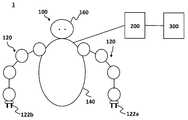
- FIG. 1is a diagram showing a schematic configuration of a system for inserting a shaft member into a hole of a segment according to an embodiment of the present invention.
- FIG. 2is a block diagram of a system according to an embodiment of the present invention.
- a system 1includes a robot 100, a control device 200 that controls the robot 100, and a user operation unit 300 that communicates with the control device 200. I have it.
- the robot 100 disclosed in the present embodimentincludes at least two robot arms 120, a robot housing 140 that supports those robot arms 120, an environment sensor 160 that senses the surrounding environment of the robot 100, and a transmission/reception unit. And 180.
- Each robot arm 120 of the present embodimentis, for example, a 6-axis articulated arm (hereinafter, also referred to as “arm”), and a robot hand (hereinafter, also referred to as “hand”) that is an end effector at the tip. It has 122.
- the robot arm 120is equipped with an actuator (not shown) having a servo motor on each rotation axis. Each servo motor is connected to the control device 200 and is configured to be operated and controlled based on a control signal sent from the control device 200.
- a 6-axis multi-joint armis used as the arm 120, but the number of axes (the number of joints) of the arm can be appropriately determined according to the application of the robot 100, the function required for it, and the like.
- the two-fingered hand 122is used as the end effector in the present embodiment, the present invention is not limited to this, and, for example, a robot hand having three or more fingers, a magnetic attraction or negative pressure suction means is provided.
- a robot hand, a robot hand equipped with a gripping means that applies the jamming phenomenon of a powder or granular material filled in a rubber film, or any other means capable of repeatedly gripping and releasing an object to be grippedCan be used.
- Each of the hands 122a and 122bis preferably configured to be rotatable around its wrist portion.
- the hand 122is equipped with a dynamic sensor that detects the amount of displacement of the hand 122 and the force, acceleration, vibration, etc. acting on the hand 122. Further, the hand 122 preferably includes a tactile sensor that detects a gripping force or a tactile sense of the hand 122.
- the robot housing 140may be installed in a fixed state on a mounting table (not shown), or may be installed on the mounting table so as to be rotatable via a rotation drive device (not shown). Good.
- the work range of the robot 100can be expanded not only to the area in front of the robot 100 but also to the area around the robot 100.
- the robot housing 140may be a vehicle equipped with a plurality of wheels, an endless track, or the like, a flying body such as a helicopter or a drone, or any other moving body, depending on the application and use environment of the robot 100. It may be mounted or the robot housing 140 may be configured as a part of such a moving body.
- the robot housing 140may have two or more legs as a walking means. Since the robot housing 140 has such moving means, the work range of the robot 100 can be made wider. Depending on the application of the robot 100, the robot arm 120 may be directly fixed to a mounting table or the like without the robot housing 140.
- the environment sensor 160senses the surrounding environment of the robot 100.
- the ambient environmentincludes, for example, electromagnetic waves (including visible light, invisible light, X-rays, gamma rays, etc.), sound, temperature, humidity, wind speed, atmospheric composition, etc. Therefore, the environment sensor 160 is a visual sensor, an X-ray.
- -Itmay include, but is not limited to, gamma ray sensors, hearing sensors, temperature sensors, humidity sensors, wind speed sensors, atmospheric analyzers, and the like.
- the environment sensor 160is shown as being integral with the robot 100 in the figure, the environment sensor 160 need not be integral with the robot 100.
- the environment sensor 160may be installed at a position away from the robot 100, or may be installed on a moving body such as a vehicle or a drone. Further, the environment sensor 160 preferably includes a GPS (Global Positioning System) sensor, an altitude sensor, a gyro sensor, and the like. Further, the environment sensor 160 detects the position of the robot 100 outdoors or indoors, and therefore, as a position detecting means, in addition to the GPS sensor, WiFi positioning, beacon positioning, self-contained navigation positioning, geomagnetic positioning, sound wave positioning, UWB (Ultra Wide Wide). (Band: Ultra Wide Band Wireless) positioning, visible light/invisible light positioning, etc. are preferably provided.
- GPSGlobal Positioning System
- the environment sensor 160detects the position of the robot 100 outdoors or indoors, and therefore, as a position detecting means, in addition to the GPS sensor, WiFi positioning, beacon positioning, self-contained navigation positioning, geomagnetic positioning, sound wave positioning, UWB (Ultra Wide Wide). (Band: Ultra Wide Band
- the environment sensor 160is shown as being integrated with the robot 100 in the figure, if the environment sensor 160 can sense the surrounding environment of the robot 100 and the position/orientation, the environment sensor 160 can be connected to the robot 100. Need not be integral.
- the environment sensor 160may be installed at a position distant from the robot 100, or may be installed in a vehicle other than the robot 100 or a moving body such as a drone.
- a 2D camera, a depth sensor, a 3D camera, an RGB-D sensor, a 3D-LiDAR sensor, a Kinect (trademark) sensor, or the likecan be used.
- the visual information obtained by the environment sensor 160is sent to the control device 200 and processed by the control device 200.
- Other environmental information obtained by the environmental sensor 160can also be transmitted to the control device 200 and used for analysis of the surrounding environment of the robot 100.
- the transmission/reception unit 180transmits/receives signals/information to/from the control device 200.
- the transmission/reception unit 180can be connected to the control device 200 by a wired connection or a wireless connection, and therefore, transmission/reception of those signals/information can be performed by a wired or wireless connection.
- the communication protocol, frequency, and the like used for transmitting and receiving these signals/informationcan be appropriately selected according to the application and environment in which the system 1 is used. Further, the transmission/reception unit 180 may be connected to a network such as the Internet.
- control device 200 in the system 1 of the present embodimentwill be described.
- the control device 200 of the system 1includes a processor 220, a storage medium 240, and a transmission/reception unit 260.
- the processor 220mainly controls the robot arm 120 of the robot 100 and the drive units and sensors (both not shown) of the body 140, controls the environment sensor 160, processes information transmitted from the environment sensor 160, controls the transmission/reception unit 260, It controls the interaction with the user operation unit 300.
- the processor 220is, for example, a central processing unit (CPU), an application specific integrated circuit (ASIC), an embedded processor, a microprocessor, a digital signal processor (DSP), or a combination thereof.
- the processor 220may be composed of one or more processors.
- the processor 220recognizes an object existing in the surrounding environment of the robot 100 based on the visual information obtained by the environment sensor 160 as processing of the information sent from the environment sensor 160.
- the processor 220 of the control device 200detects the shape of the object included in the visual information based on the visual information (image information and depth information in the image) obtained by the environment sensor 160, and the control device
- the object included in the visual informationis specified by referring to the shape data of the object stored in the storage medium 240 of the computer 200 or the shape data of the object existing on the network to which the control device 200 is connected. To do.
- a feature point of the object shapeis referred to, a lookup table associated with shape data of a known object is referred to, or an unknown object is identified by using arbitrary machine learning or AI technology. It can be executed by associating with shape data.
- the usercan specify the object by the user's operation of specifying the object using the user input unit 350 of the user operation unit 300 described later.
- the objectincludes, for example, one or more segments having a hole formed therein and a shaft member inserted into the hole of the segment.
- the shaft membermay be a shaft, a pin, a bolt, a screw or the like.
- a nut fastened to a boltmay also be included in the object.
- the storage medium 240controls a computer program that controls the robot 100, a computer program that processes information transmitted from the environment sensor 160, a computer program that interacts with the user operation unit 300, and a transmission/reception unit 260. It stores computer programs, etc.
- the storage medium 240stores software or a program that causes a computer to perform the operation described below to cause the function of the control device 200.
- storage medium 240stores a computer program executable by processor 220, including instructions for performing the methods described below with reference to FIGS. 3 and 6A and 6B.
- the storage medium 240preferably stores a look-up table associated with the known object shape data as described above.
- the storage medium 240includes the state of each part (servo (not shown), hand 122, etc.) of the robot arm 120 of the robot 100, information transmitted from the environment sensor 160, information transmitted from the user operation unit 300, and control signals. Etc. is also stored at least temporarily.
- the storage medium 240is preferably a non-volatile storage medium that is a non-transitory computer-readable medium that retains the storage state even when the power of the control device 200 is turned off.
- HDDhard disk drive
- SSDsolid-state storage device
- optical disk storagesuch as compact disk (CD)/digital versatile disk (DVD)/Blu-ray disk (BD)
- NVRAMnonvolatile random access memory
- flash memoryComposed of storage.
- the transmission/reception unit 260transmits/receives signals/information to/from the robot 100 and transmits/receives signals/information to/from the user operation unit 300.
- the control device 200can be connected to the robot 100 and the user operation unit 300 by a wired connection or a wireless connection, respectively, and therefore, transmission/reception of signals and information thereof can be performed by a wired or wireless connection.
- the communication protocol, frequency, and the like used for transmitting and receiving these signals/informationcan be appropriately selected according to the application and environment in which the system 1 is used.
- the transmission/reception unit 260may be connected to a network such as the Internet.
- control device 200is shown as being independent of the robot 100 and the user operation unit 300 in FIGS. 1 and 2, it is not limited to this.
- the control device 200may be provided inside the housing 140 of the robot 100, or the control device 200 may be configured integrally with the user operation unit 300.
- the number of robots 100 used in the present system 1is not limited to one, and a plurality of robots 100 may be operated independently or in cooperation with each other.
- the single control device 200may control the plurality of robots 100, or the plurality of control devices 200 may cooperate to control the plurality of robots 100.
- the user operation unit 300 of the system 1includes a processor 320, a storage medium 340, an input device 350, a transmission/reception unit 360, and a display 370.
- the processor 320mainly controls the interaction with the control device 200, the processing based on the input performed by the user via the input device 350, the control of the transmission/reception unit 260, and the display of the display 370.
- the processor 320interprets a user input input by the input device 350, generates an operation instruction signal for causing the robot 100 to perform an operation according to the interpretation, and transmits the operation instruction signal to the control device 200.
- the processor 220 of the control device 200Based on the operation instruction signal, the processor 220 of the control device 200 generates one or a plurality of control commands for operating the drive units (not shown) of the robot arm 120 and the body 140 of the robot 100 and the environment sensor 160. To do.
- the processor 320 of the user operation unit 300is composed of, for example, a central processing unit (CPU), an application specific integrated circuit (ASIC), an embedded processor, a microprocessor, a digital signal processor (DSP), or a combination thereof.
- the processor 320may be composed of one or more processors.
- the processor 320 of the user operation unit 300is configured to generate a UI (user interface) screen to be presented to the user and display it on the display 370.
- the UI screen(not shown) preferably includes, for example, a selection button that hierarchically provides the user with a plurality of options.
- the processor 320may display a real space image or moving image of the surrounding environment of the robot 100 captured by the environment sensor 160 of the robot 100 on the display 370, or the robot captured by the environment sensor 160 of the robot 100.
- An image or moving image of a virtual spacemay be generated based on the image or moving image of the surrounding environment of 100 and displayed on the display 370.
- the processor 320When the processor 320 generates an image or a moving image of the virtual world based on an image or a moving image of the real world, the processor 320 associates the coordinate system of the real world with the coordinate system of the virtual world, for example. Build a correlation. Further, the image or moving image in the real space and the image or moving image in the virtual space (simulation space) may be displayed on the display 370 at the same time. Furthermore, the UI screen may be displayed by being superimposed on the image or moving image of the environment of the robot 100 or the image or moving image of the virtual space. The image or moving image of the virtual world (simulation space) generated based on the image or moving image of the real environment of the surrounding environment of the robot 100 also includes objects existing in the surrounding environment of the robot 100.
- the storage medium 340controls a computer program that interacts with the control device 200, a computer program that performs a process based on an input interactively performed by the user on the UI screen via the input device 350, and the transmission/reception unit 260.
- a computer program, a computer program for displaying the display 370, and the likeare stored.
- the storage medium 240is imaged by the environment sensor 160 of the robot 100 and sent to the user operation unit 300 via the control device 200, or an image or moving image of the surrounding environment of the robot 100, or the surrounding environment of the robot 100. It is possible to at least temporarily store the image or moving image of the virtual space (simulation space) generated by the processor 320 based on the image or moving image.
- the storage medium 340 of the user operation unit 300is also preferably configured by a non-volatile storage medium that is a non-transitory computer-readable medium that retains the storage state even when the power of the unit 300 is turned off.
- Optical disk storagesuch as hard disk drive (HDD), solid-state storage device (SSD), compact disk (CD), digital versatile disk (DVD), Blu-ray disk (BD), non-volatile random access memory (NVRAM), flash memory It is composed of non-volatile storage such as.
- the input device 350for example, a keyboard, a mouse, a joystick, etc. can be used. Furthermore, it is possible to use a device called a tracker that can track the position and orientation by using infrared rays and has a trigger button.
- the display 370includes a touch panel type display device, the touch panel can be used as an input device.
- the display 370is a head mounted display used as a display device such as VR (virtual reality)/AR (augmented reality) or MR (mixed reality), and has a user's eye gaze tracking function
- the gaze tracking functioncan be used as an input device.
- a device having a gaze tracking function but not a displaycan use the gaze tracking function as an input device.
- a voice input devicecan be used as an input device. These are illustrated as examples of the input device 350, and means that can be used for the input device 350 are not limited to these. Moreover, you may use it as the input device 350 combining arbitrary means as mentioned above.
- the userselects, for example, a selection button on the UI screen displayed on the display 370, inputs a character, or the robot imaged by the environment sensor 160 of the robot 100.
- a selection button on the UI screen displayed on the display 370inputs a character, or the robot imaged by the environment sensor 160 of the robot 100.
- the transmission/reception unit 360transmits/receives signals/information to/from the control device 200.
- the user operation unit 300can be connected to the control device 200 by a wired connection or a wireless connection, and therefore, the transmission/reception of those signals/information can be performed by a wired or wireless connection.
- the communication protocol, frequency, etc. used for transmitting/receiving the signal/informationcan be appropriately selected according to the application, environment, etc. in which the system 1 is used.
- the transmission/reception unit 360may be connected to a network such as the Internet.
- the display 370is used as a display monitor, a computer/tablet device (including a touch panel type display), a display device such as VR (virtual reality)/AR (augmented reality) or MR (mixed reality).
- a display devicesuch as VR (virtual reality)/AR (augmented reality) or MR (mixed reality).
- VRvirtual reality
- ARaugmented reality
- MRmixed reality
- a display device of any formsuch as a head mounted display or a projector can be used.
- the head-mounted displaywhen a head-mounted display is used as the display 370, the head-mounted display provides an image or a moving image in which the left and right eyes of the user have parallax, thereby allowing the user to perceive a three-dimensional image or moving image.
- the head mounted displayhas a motion tracking function, it is possible to display an image or a moving image according to the position and direction of the head of the user wearing the head mounted display.
- the line-of-sight tracking functioncan be used as an input device.
- FIG. 3is a flowchart showing a first operation of inserting the shaft member into the hole of the segment according to the embodiment of the present invention.
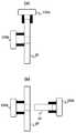
- 4A and 4Bare diagrams showing movement of the hand in the first operation of inserting the shaft member into the hole of the segment according to the embodiment of the present invention.
- FIG. 5is a diagram showing various operation pattern examples of a hand for searching a hole of a segment.
- Step S300First, through the UI screen of the user operation unit 300 (FIG. 2), the shaft member and the segment through which it is to be specified are designated, an instruction to pass the shaft member through the hole of the segment is given, and this is executed (see FIG. 3). Step S300).
- a control command for passing the shaft member through the hole of the segmentis generated through the UI screen. It can be done by Alternatively, if the segment and the shaft member are recognized as objects by the control device 200 and it is associated that the shaft member is to be inserted into the hole of the segment, the user operation unit 300 (Fig.
- a control command for passing the designated shaft member through the hole of the designated segmentcan be generated.
- the control command thus generatedis sent from the user operation unit 300 to the control device 200.
- the processor 220 of the control device 200generates an instruction to execute the motion control of the robot 100 according to the control command, and executes the instruction.
- the segment 10is grasped by the hand 122a and moved so as to be in a substantially vertical posture, and then the tip of the hand 122b is reached.
- the segmentis supported by the hand 122b by leaning against the hand 122b so as to come into contact with it, and the grip of the segment by the hand 122a is released (step S310 in FIG. 3).
- the segment 10has a posture that can be supported by the hand 122b in advance, the operation of gripping the segment 10 with the hand 122a and moving it to a substantially vertical posture can be omitted.
- Supporting the segment 10 with the hand 122bis particularly effective when the segment 10 is not fixed and is in an unstable state, but may be performed when the segment 10 is fixed. For example, even if the segment 10 is fixed with an adhesive or the like, when the segment 10 is pushed by the hand 122a, the adhesive portion may be peeled off and the segment 10 may move. In order to prevent such a situation, it is preferable that the fixed segment 10 is also supported by the hand 122b.
- the gripping of the segment 10 by the hand 122acan be controlled in any manner.
- the segment 10 in the real space detected by the environment sensor 160 of the robot 100may be gripped so as to sandwich the periphery of the segment 10 (see FIG. 4A(a)), or the two claws of the hand 122a may be inserted into the holes of the segment 10. And grip them by abutting them on the inner surface of the hole, or by inserting one claw of the hand 122a into the hole of the segment 10 and bringing the other claw into contact with the outer edge of the segment 10 with those claws. It is possible to grip the inner surface of the hole of the segment 10 and the outer edge of the segment 10 so as to sandwich them.
- How the user grasps the segment 10 with the hand 122acan be appropriately selected by the user using the user operation unit 300 according to the posture of the segment 10 placed in the real space, the relative position of the robot 100 with respect to the posture, and the like. It is possible, or it can be appropriately selected by operating the control device 200 according to a predetermined algorithm or the result of machine learning.
- the shaft member 15is gripped by the hand 122a to align the hole with the segment 10 (step S320 in FIG. 3).
- the hand 122apreferably grips one end portion of the shaft member 15 in the vicinity thereof.
- the hand 122agrips the shaft member 15 depending on which part of the shaft member 15 is held and in which posture. It can be arbitrarily determined as long as it does not hinder the operation of inserting it into the hole of 10.
- the alignment of the shaft member 15 with respect to the hole of the segment 10is preferably performed by operating the hand 122a and its arm 120 so that the central axis of the shaft member 15 in the longitudinal direction coincides with the central axis of the hole of the segment 10. Done in.
- the positions and orientations of the segment 10 and the shaft member 15are monitored by the environment sensor 160 of the robot 100, and the processor 220 of the control device 200 controls the above-described operation of the arm 120 and the hand 122a based on the information sent from the environment sensor 160. ..
- the hand 122a holding the shaft member 15 and the arm 120are operated to move the shaft member 15 toward the segment 10 with the end portion of the shaft member 15 toward the hole of the segment 10.
- Whether or not the shaft member 15 contacts the segment 10is detected by whether or not a reaction force of a predetermined amount or more acts on any of the hands 122a and 122b (step S330 in FIG. 3).
- the shaft member 15in the longitudinal direction by a predetermined distance (for example, a distance of a third position of the thickness of the segment 10) or more without detecting such a reaction force.
- a predetermined distancefor example, a distance of a third position of the thickness of the segment 10.
- the operation of inserting the shaft member 15 into the hole of the segment 10is continuously performed (step S360 in FIG. 3), and the shaft member 15 is further moved in the longitudinal direction by a predetermined distance (at least at the end of the shaft member 15).
- the shaft member 15is moved through the hole of the segment 10 (see FIG. 4B(e)) by moving the segment member 10 so that the shaft member 15 is inserted into the hole of the segment 10. To do.
- an operation for searching the hole of the segment 10is performed as shown in FIG. 4B(c) (step S340 in FIG. 3).
- This actioncauses the hand 122a and arm holding the shaft member 15 to move the end of the shaft member 15 over the segment 10 while pressing the end of the shaft member 15 against the segment 10 with some force.
- Including operating 120As the movement pattern of the end portion of the shaft member 15 on the segment 10, for example, movement that draws a spiral as shown in FIG. 5A, zigzag translational movement as shown in FIG. 5B, and FIG. Patterns such as moving in a certain direction while drawing a circle as shown in Fig. 5, rotating while drawing an ellipse as shown in Fig. 5(d), and moving like drawing a figure 8 as in Fig. 5(e) are possible. .. These movement patterns are listed as examples, and the movement patterns of the ends of the shaft member 15 on the segment 10 are not limited thereto.
- the other surface of the segment 10is supported while the end of the shaft member 15 is moved over the segment 10 while thus pushing the end of the shaft member 15 against the segment 10 with some force with the hand 122a.
- a moment forceacts on the segment 10 to move the segment 10, and it may not be possible to continue the hole searching operation of the segment 10.
- the force pushing the hand 122b against the segment 10causes the hand 122a to press the shaft member 15 onto the segment 10. It is the same as the force to push it on 10. In this manner, by moving the hand 122b so that at least a part of the tip of the shaft member 15 continues to be located in the working area of the hand 122b supporting the other surface of the segment 10, a moment is generated in the segment 10. It is possible to prevent that.
- the action area of the hand 122bis, for example, an area between two fingers when the hand 122b has a two-finger configuration, and those areas when the hand 122b has a three-finger configuration. It is a triangular area formed by three fingers.
- the search for the hole of the segment 10is continued while pressing the shaft member 15 against the segment 10, and when the end of the shaft member 15 reaches the hole of the segment 10, the end of the shaft member 15 slightly goes into the hole of the segment 10. Enter (see FIG. 4B(d)).
- the hand 122a gripping and moving the shaft member 15moves, for example, a reaction force acting on the shaft member 15 pressed against the segment 10 or a change in vibration transmitted to the shaft member 15 moving on the segment 10, a shaft Displacement or acceleration of the member 15 in the longitudinal direction occurs. Further, a reaction force acting on the hand 122b supporting the segment 10 or a change in vibration occurs.
- step S360 in FIG. 3After it is detected that the end of the shaft member 15 has entered the hole of the segment 10, the operation of inserting the shaft member 15 into the hole of the segment 10 is performed (step S360 in FIG. 3), and the shaft member 15 is moved in its longitudinal direction. By a predetermined distance (at least the distance at which the end of the shaft member 15 projects from the opposite side of the hole of the segment 10) to pass the shaft member 15 through the hole of the segment 10 (see FIG. 4B(e)). The operation of inserting the shaft member 15 into the hole of the segment 10 is completed.
- the shaft member 15can be passed through the hole of the segment 10 which is not fixed.
- the operation using the two arms 120 and the hand 122 provided in one robot 100has been described as an example, but the configuration for performing the above operation is not limited to this.
- the above-described operationcan be performed using one arm 120 and the hand 122 of the one robot 100 of the plurality of robots 100 and the one arm 120 and the hand 122 of the other robot 100.
- FIG. 6A, FIG. 6B, and FIG. 7A, FIG. 7Bas a second operation example of the method of inserting the shaft member into the hole of the segment according to the embodiment of the present invention, The operation of inserting the bolt and stopping with the nut will be described.
- 6A and 6Bare flowcharts showing a second operation of inserting the shaft member into the hole of the segment according to the embodiment of the present invention.
- 7A and 7Bare diagrams showing the movement of the hand in the second operation of inserting the bolt into the hole of the segment and stopping with the nut according to the embodiment of the present invention.
- step S600 in FIG. 6AThe instruction to tighten with a nut through a hole in a segment is, for example, a control command to specify a bolt and a segment and a nut through which it is passed on a UI screen, and then through a bolt through the hole in the segment, with a nut. Is also generated through the UI screen.
- the controller 200recognizes the segment, the bolt and the nut as objects, and the bolt should be inserted into the hole of the segment, and the nut should be fastened to the bolt.
- the boltis tightened with the designated nut through the designated bolt through the hole of the designated segment.
- a control command to the effectmay be generated. In this case, for example, by specifying "multiple segments”, “bolts", and “nuts” in that order, a control command that means “pass the bolts through the holes of multiple segments and fasten the nuts to the bolts" is generated. It is also possible to do so.
- the control command thus generatedis sent from the user operation unit 300 to the control device 200.
- the processor 220 of the control device 200generates an instruction to execute the motion control of the robot 100 according to the control command, and executes the instruction.
- the second segment 10bis grasped by the hand 122a and moved so as to be in a substantially vertical posture.
- the hand 122bgrips the nut 20 so as to sandwich the outer periphery of the nut 20. Then, the second segment 10b held by the hand 122a is leaned against the nut 20 held by the hand 122b so that the second segment 10b is supported by the hand 122b.
- the first segment 10ais grasped by the hand 122a and moved so as to be in a substantially vertical posture, and the first segment 10a is leaned against the second segment 10b so as to be in contact with the second segment 10b.
- the grip of the first segment 10a by the hand 122ais released (step S605 in FIG. 6A).
- the segment 10bhas a posture that can be supported by the hand 122b in advance, the operation of gripping the segment 10b with the hand 122a and moving it to a substantially vertical posture can be omitted.
- the fact that the support of the segment 10may be performed when the segment 10 is fixed, and that the gripping of the segment 10 by the hand 122a can be controlled in an arbitrary manner is as described in the first operation above. Is.
- the head portion of the bolt 30is gripped by the hand 122 to align the first segment 10a with the hole (step S610 in FIG. 6A).
- the posture in which the hand 122a grips the head portion of the bolt 30is arbitrary as long as the hand 122a does not interfere with the operation of inserting the shaft portion of the bolt 30 into the hole of the segment 10 and rotating the bolt 30. It is possible to decide.
- the alignment of the shaft portion of the bolt 30 with respect to the hole of the segment 10is preferably performed so that the central axis of the bolt 30 in the longitudinal direction coincides with the central axis of the hole of the first segment 10a. This is performed by operating 122a.
- the position and orientation of the segment 10 and the bolt 30are monitored by the environment sensor 160 of the robot 100, and the processor 220 of the control device 200 controls the above-described operation of the arm 120 and the hand 122 based on the information sent from the environment sensor 160.
- the hand 122a holding the bolt 30 and its arm 120are operated to move the bolt 30 toward the first segment 10a so that the end of the bolt 30 is directed toward the hole of the first segment 10a.
- the bolt 30can be moved in the longitudinal direction by a predetermined distance (for example, a distance at a position of a third of the thickness of the segment 10a) or more. It is determined that the shaft portion of the bolt 30 could be passed through the hole of the first segment 10a because the end of the bolt 30 was aligned with the hole of the first segment 10a. In this case, the bolt 30 is further moved in the longitudinal direction to insert the bolt into the hole of the first segment 10a (step S630 in FIG. 6A).
- a predetermined distancefor example, a distance at a position of a third of the thickness of the segment 10a
- an operation for searching the hole of the first segment 10ais performed as shown in FIG. 7A(c) (step S620 in FIG. 6A).
- This actioninvolves holding the bolt 30 so that the end of the bolt 30 is moved over the first segment 10a while pressing the end of the bolt 30 against the first segment 10a with some force.
- 122a and its arm 120are also in this example, as the movement pattern of the bolt end portion on the segment 10a.
- various patterns as shown in FIG. 5, for example,can be used as shown in FIG. 5, for example.
- the segmentDepending on the relationship with the position of the hand 122b supporting the other surface of 10, the moment force acts on the segment 10 to cause the segments 10a and 10b to move, and the search operation of the hole of the first segment 10a may be performed. It may not be possible to continue. In order to prevent this, it is preferable to move the hand 122b in synchronization with the movement of the bolt 30 by the hand 122a. Specifically, the hand 122b is pressed against the second segment 10b and moved so as to follow the movement of the bolt 30 by the hand 122b.
- the force pressing the hand 122b against the second segment 10bis:
- the hand 122ahas the same force as pressing the bolt 30 against the first segment 10a. In this way, by moving the hand 122b so that at least a part of the tip of the bolt 30 continues to be located in the operation area of the other hand 122b, it is possible to prevent a moment from being generated in the segments 10a and 10b. is there.
- the operation area of the hand 122bis an area surrounded by the outer circumference of the nut 20 gripped by the hand 122b.
- Operation of moving the bolt 30 in the longitudinal direction to insert the shaft portion of the bolt 30 into the hole of the first segment 10a after it is detected that the end of the bolt 30 has entered the hole of the first segment 10a.Is performed (step S630 of FIG. 6A).
- the bolt 30is inserted into the hole of the first segment 10a. Whether or not the bolt 30 is inserted into the hole of the first segment 10a can be determined by detecting whether or not the bolt 30 can be moved in the longitudinal direction by the thickness of the first segment 10a.
- the bolt 30can be moved in the longitudinal direction by a predetermined distance (for example, a distance at a position of 1 ⁇ 3 of the thickness of the second segment 10b) or more without detecting a reaction force of a predetermined amount or more. It is judged that the shaft portion of the bolt 30 could be passed through the hole of the second segment 10b because the end of the bolt 30 was aligned with the hole of the second segment 10b. In this case, the bolt 30 is further moved along the longitudinal direction to insert the bolt into the hole of the second segment 10b (step S650 in FIG. 6B).
- a predetermined distancefor example, a distance at a position of 1 ⁇ 3 of the thickness of the second segment 10b
- step S640If a reaction force of a predetermined amount or more is detected, it is determined that the end of the bolt 30 is not inserted in the hole of the second segment 10b and is in contact with the vicinity of the hole of the segment. In this case, the same operations as those in steps S620, S625, and S630 described above are repeated, and the bolt 30 is inserted into the hole of the second segment 10b (steps S640, S645, and S650 in FIG. 6B; (E) and FIG. 7B(f))). If the bolt 30 passes through the hole of the first segment 10a, the first segment 10a also moves together with the bolt 30 during the operation of searching for the hole of the second segment 10b in step S640.
- step S640it is possible to determine whether or not the bolt 30 passes through the hole of the first segment 10a by detecting whether or not the load applied to the hand 122a has increased in the operation of step S640.
- the bolt 30is inserted into the hole of the second segment 10b. Whether or not the bolt 30 is inserted into the hole of the second segment 10b can be determined by detecting whether or not the bolt 30 can be moved in the longitudinal direction by the thickness of the second segment 10b.
- the arm 120 and the hand 122 holding the bolt 30are operated to move the bolt 30 in the longitudinal direction until the bolt 30 and the nut 20 come into contact with each other and a reaction force of a predetermined amount or more acts on one of the hands 122a and 122b.
- the operation of continuing the movementis continued, and after the bolt 30 and the nut 20 come into contact with each other and a reaction force of a predetermined value or more is detected (step S655 in FIG. 6B), the arm 120 and the hand 122a holding the bolt 30 are operated, It is determined whether or not the bolt 30 can be moved in an arbitrary direction perpendicular to its longitudinal direction (step S660 in FIG. 6B).
- the hand 122b gripping the nut 20moves so as to follow the movement of the bolt 30 as described above, and at least a part of the end of the bolt 30 is located inside the outer peripheral edge of the nut 20. Therefore, when a reaction force of a predetermined amount or more is detected, the tip of the bolt 30 is in contact with the edge of the nut 20 or is in the screw hole of the nut 20. When the tip of the bolt 30 is in the threaded hole of the nut 20, the end of the bolt 30 cannot be moved on the nut.
- step S660Since it can be determined that the tip of the bolt 30 is in the screw hole of the nut 20, in this case, the operation shifts to the operation of fastening the bolt 30 and the nut 20 (step S675 in FIG. 6B).
- step S665 in FIG. 6Bthe operation of searching the screw hole of the nut 20 is performed (step S665 in FIG. 6B).
- This actionoperates the hand 122a and the arm 120 holding the bolt 30 such that the end of the bolt 30 is moved over the nut 20 while pressing the end of the bolt 30 against the nut 20 with some force.
- the hand 122b and the arm 120 holding the nut 20are moved so that the nut 20 is moved over the end of the bolt 30 while pressing the nut 20 against the end of the bolt 30 with some force.
- various patterns as shown in FIG. 5can be used as the movement pattern of the bolt end portion on the nut 20.
- the bolts 20can be passed through the holes of the plurality of unfixed segments 10a and 10b to be fixed with the nuts 30.
- the operation using the two arms 120 and the hand 122 provided in one robot 100has been described as an example, but the configuration for performing the above operation is not limited to this.
- the above-described operationcan be performed using one arm 120 and the hand 122 of the one robot 100 of the plurality of robots 100 and the one arm 120 and the hand 122 of the other robot 100.
- the number of segmentsis not limited to two.
- the number of segmentsis one, only one segment is designated in step S600 shown in FIG. 6A, only that segment is moved in step S610, and steps S635 to S650 are omitted.
- the number of segmentsis n (n is 3 or more)
- all of those segmentsare designated in step S600 shown in FIG. 6A, and those segments are designated as the nth, n ⁇ 1th, and nth segments in step S610.
- the second and first positionsare sequentially moved to lean against each other, and steps S635 to S650 are repeated as many times as necessary according to the number of segments.
- step S605the gripping of the nut 20 by the hand 122b is not performed, and therefore, the second segment 10b is supported not by the hand of the nut 20 but by the tip of the hand 122b.
- step 650after the bolts 30 are inserted into the holes of all the segments 10 in step 650, the nuts 20 are gripped by the hand 122b until a reaction force of a predetermined amount or more acts on one of the hands 122a and 122b.
- the bolt 30is moved toward the tip of the bolt 30 that is passed through the holes of all the segments 10.
- step S655 of FIG. 6Bafter a reaction force equal to or larger than a predetermined value is detected (step S655 of FIG. 6B), the operations of steps S600 to S675 are performed in the same manner as above.
Landscapes
- Engineering & Computer Science (AREA)
- Mechanical Engineering (AREA)
- Robotics (AREA)
- Human Computer Interaction (AREA)
- Manipulator (AREA)
Abstract
Description
Translated fromJapanese本発明は、セグメントの孔にボルト等のシャフト部材を挿入する方法および制御装置に関する。The present invention relates to a method and a control device for inserting a shaft member such as a bolt into a hole of a segment.
構造物の組み立ての要素技術として、複数のセグメントに形成された孔にシャフトを通してそれらのセグメントを連結したり、セグメントに形成されたボルト孔にボルトを通し、それをナットで締結したりすることが用いられる。孔にシャフト部材を通す作業を自動化するために、種々の提案がされている。As an elemental technology for assembling a structure, it is possible to connect the segments through a hole formed in a plurality of segments or to insert a bolt into a bolt hole formed in the segment and fasten it with a nut. Used. Various proposals have been made for automating the work of passing the shaft member through the hole.
特許文献1は、第1のロボットアームのエンドエフェクタで、第2のロボットアームの位置合わせ用エンドエフェクタにより支持されるワークの先端側よりもワーク嵌合部から離れたワークの根元側を支持して、第1及び第2の2つのロボットアームを協調させて動作させることにより、ワークをワーク嵌合部に嵌合させるロボットシステムが開示されている。この先行技術には、ワーク嵌合部を探るために、ワークをワーク嵌合部に対して平面上で並進移動させることが記載されている。
また近年では、ロボットアームを用いてシャフト部材の先端をセグメントの孔付近に当接させながら渦巻き状に移動させ、セグメントの孔を探る手法が提案されている(非特許文献1)。Also, in recent years, a method has been proposed in which a robot arm is used to move the tip of a shaft member in the shape of a spiral while abutting the tip of the shaft member in the vicinity of the hole of the segment to search for the hole of the segment (Non-Patent Document 1).
しかしながら、いずれの先行技術も、孔にシャフト部材が通されるセグメントが予め固定されているか、少なくとも容易に動かないように設置されていることを前提にしており、不安定な状態にあるセグメントの孔にシャフト部材を通すことまでは行うことができない。例えば、固定されず単に自立しているだけのセグメントの孔にシャフト部材を通すようなケースでは、シャフト部材を挿入する際にシャフト部材が孔の縁に少しでも当たると、セグメントがシャフト部材に押されてセグメントの位置や向きが変わってシャフト部材と孔との相対位置がずれたり、セグメントがシャフト部材に押されて倒れたりしてしまう。However, both of the prior arts assume that the segment through which the shaft member is passed through the hole is fixed in advance, or at least is installed so as not to move easily. It is not possible to pass the shaft member through the hole. For example, in the case where the shaft member is passed through the hole of a segment that is not fixed and is merely self-supporting, if the shaft member hits the edge of the hole even slightly when the shaft member is inserted, the segment will push against the shaft member. As a result, the position or orientation of the segment changes, the relative position of the shaft member and the hole shifts, or the segment is pushed by the shaft member and falls.
また、例えば2つのセグメントの孔にシャフト部材を通す場合には、各セグメントの孔が予め正確に互いに位置合わせされていないと、それらのセグメントにシャフト部材を通すことはできない。上記の先行技術では、各セグメントの孔が予め互いに位置合わせされていないと、2つセグメントのうちの最初のセグメントの孔を検出してそこにシャフト部材を挿入することができても、その次のセグメントにシャフト部材が当たってそれ以上シャフト部材を挿入することができない。さらには、シャフト部材が次のセグメントを押して、次のセグメントの位置がずれたり、次のセグメントが倒れたりすることが生じうる。Also, for example, when passing the shaft member through the holes of the two segments, the shaft member cannot be passed through the segments unless the holes of the segments are accurately aligned with each other in advance. In the above prior art, if the holes of each segment were not pre-aligned with each other, the hole of the first of the two segments could be detected and the shaft member inserted there, but The shaft member hits the segment of and the shaft member cannot be inserted any more. Furthermore, the shaft member may push the next segment, which may cause the position of the next segment to shift or the next segment to fall.
本発明の一態様によれば、本発明による制御装置は、セグメントの孔にシャフト部材を挿入するように、各々がエンドエフェクタを有する少なくとも2つのロボットアームを制御する制御装置であって、
一方のエンドエフェクタでセグメントを支持する動作と、
他方のエンドエフェクタでシャフト部材を把持する動作と、
シャフト部材の端部をセグメントの孔に向けて、シャフト部材をセグメントの方向へ移動させる動作と、
シャフト部材がセグメントに接触したことが検出された場合に、シャフト部材の端部をセグメントに押し当てながらシャフト部材の端部をセグメントの上で移動させる動作と、
シャフト部材の端部がセグメントの孔に入ったことが検出された場合に、シャフト部材をセグメントの孔に挿入する動作と、を実行するように構成されたプロセッサを備えている。According to one aspect of the invention, a controller according to the invention is for controlling at least two robot arms each having an end effector so as to insert a shaft member in a hole of a segment,
The operation of supporting the segment with one end effector,
The operation of gripping the shaft member with the other end effector,
An operation of moving the shaft member in the direction of the segment with the end of the shaft member facing the hole of the segment;
Moving the end of the shaft member over the segment while pressing the end of the shaft member against the segment when it is detected that the shaft member has contacted the segment;
A processor configured to perform an operation of inserting the shaft member into the segment hole when it is detected that the end of the shaft member has entered the segment hole.
また、本発明の他の態様によれば、本発明による方法は、各々がエンドエフェクタを有する少なくとも2つのロボットアームによってセグメントの孔にシャフト部材を挿入する方法であって、
一方のエンドエフェクタでセグメントを支持するステップと、
他方のエンドエフェクタでシャフト部材を把持するステップと、
シャフト部材の端部をセグメントの孔に向けて、シャフト部材をセグメントの方向へ移動させるステップと、
シャフト部材がセグメントに接触したことが検出された場合に、シャフト部材の端部をセグメントに押し当てながらシャフト部材の端部をセグメントの上で移動させるステップと、
シャフト部材の端部がセグメントの孔に入ったことが検出された場合に、シャフト部材をセグメントの孔に挿入するステップと、を含む。According to another aspect of the invention, the method according to the invention is a method of inserting a shaft member into a hole of a segment by at least two robot arms each having an end effector,
Supporting the segment with one end effector,
Gripping the shaft member with the other end effector,
Moving the shaft member toward the segment with the end of the shaft member facing the hole in the segment;
Moving the end of the shaft member over the segment while pressing the end of the shaft member against the segment when it is detected that the shaft member contacts the segment;
Inserting the shaft member into the hole of the segment when it is detected that the end of the shaft member has entered the hole of the segment.
また、本発明の他の態様によれば、本発明によるプロセッサによって実行可能なコンピュータ・プログラムは、上記方法を実施する命令を含む。According to another aspect of the present invention, a computer program executable by the processor according to the present invention includes instructions for implementing the above method.
さらに、本発明の他の態様によれば、本発明による非一時的なコンピュータ可読媒体は、上記方法を実施する命令を含む、上記媒体に記憶され、プロセッサによって実行することができるコンピュータ・プログラムを含む。Furthermore, according to another aspect of the present invention, a non-transitory computer readable medium according to the present invention comprises a computer program stored on the medium and capable of being executed by a processor, the instructions including instructions for implementing the method. Including.
以下、本発明の実施の形態を図面を参照して説明する。Embodiments of the present invention will be described below with reference to the drawings.
図1は、本発明の一実施形態に係るセグメントの孔にシャフト部材を挿入するシステムの概略構成を示す図である。図2は、本発明の一実施形態に係るシステムのブロック図である。FIG. 1 is a diagram showing a schematic configuration of a system for inserting a shaft member into a hole of a segment according to an embodiment of the present invention. FIG. 2 is a block diagram of a system according to an embodiment of the present invention.
図1及び図2に示すように、本発明の一実施形態に係るシステム1は、ロボット100と、ロボット100を制御する制御装置200と、制御装置200と相互に通信するユーザ操作ユニット300とを備えている。As shown in FIGS. 1 and 2, a
本実施形態に開示するロボット100は、一例として、少なくとも2つのロボットアーム120と、それらのロボットアーム120を支持するロボット筐体140と、ロボット100の周囲環境をセンシングする環境センサ160と、送受信ユニット180とを備えている。As an example, the
本実施形態の各々のロボットアーム120は、例えば6軸の多関節アーム(以下、「アーム」とも称する。)であり、先端にはエンドエフェクタであるロボットハンド(以下、「ハンド」とも称する。)122を有している。ロボットアーム120は各回転軸にサーボモータを有するアクチュエータ(不図示)を備えている。各サーボモータは制御装置200に接続されており、制御装置200から送られる制御信号に基づいて動作制御されるように構成されている。本実施形態では、アーム120として6軸の多関節アームを用いているが、アームの軸数(関節数)はロボット100の用途やそれに求められる機能等に応じて適宜定めることができる。また、本実施形態ではエンドエフェクタとして2本指のハンド122を用いているが、これに限らず、例えば、3本あるいはそれ以上の指を備えたロボットハンド、磁力あるいは負圧による吸着手段を備えたロボットハンド、ゴム膜内に充填された粉粒体のジャミング(詰まり)現象を応用した把持手段を備えたロボットハンド、その他任意の手段により把持対象物のグリップとリリースを繰り返し行うことができるものを用いることができる。各ハンド122a,122bは、その手首部分を中心として回転可能に構成されていることが好ましい。Each
ハンド122には、ハンド122の変位量、ハンド122に作用する力・加速度・振動等を検出する動力学センサが備えられている。さらに、ハンド122は、ハンド122による把持力や触覚を検出する触覚センサを備えていることが好ましい。The hand 122 is equipped with a dynamic sensor that detects the amount of displacement of the hand 122 and the force, acceleration, vibration, etc. acting on the hand 122. Further, the hand 122 preferably includes a tactile sensor that detects a gripping force or a tactile sense of the hand 122.
ロボット筐体140は、例えば、載置台(不図示)の上に固定した状態で設置してもよく、あるいは、載置台の上に回転駆動装置(不図示)を介して旋回可能に設置してもよい。ロボット筐体140を載置台の上に旋回可能に設置した場合には、ロボット100の作業範囲をロボット100の正面の領域だけでなく、ロボット100の周囲の範囲に広げることができる。さらには、ロボット筐体140は、ロボット100の用途や使用環境に応じて、複数の車輪や無限軌道等を備えた車両、船舶、潜水機、ヘリコプターやドローン等の飛行体、その他の移動体に載置されていてもよく、あるいは、ロボット筐体140がそのような移動体の一部として構成されていてもよい。さらには、ロボット筐体140は歩行手段として2足またはそれ以上の足を有していてもよい。ロボット筐体140がそのような移動手段を有することにより、ロボット100の作業範囲をより広範囲とすることができる。ロボット100の用途によっては、ロボットアーム120はロボット筐体140を介さずに載置台等に直接固定されていてもよい。The
環境センサ160は、ロボット100の周囲環境をセンシングする。周囲環境には例えば、電磁波(可視光線、非可視光線、X線、ガンマ線等を含む)、音、温度、湿度、風速、大気組成等が含まれ、したがって環境センサ160は、視覚センサ、X線・ガンマ線センサ、聴覚センサ、温度センサ、湿度センサ、風速センサ、大気分析装置等を含み得るが、これらに限定されない。なお、図では環境センサ160がロボット100と一体であるように示されているが、環境センサ160はロボット100とは一体でなくてもよい。例えば、環境センサ160はロボット100から離れた位置に設置されていたり、車両やドローン等の移動体に設置されていてもよい。また、環境センサ160は、GPS(Grobal Positioning System)センサ、高度センサ、ジャイロセンサ等を備えていることが好ましい。さらに、環境センサ160は、ロボット100の屋外または屋内における位置検出のため、位置検出手段として、上記GPSセンサの他、WiFi測位、ビーコン測位、自立航法測位、地磁気測位、音波測位、UWB(Ultra Wide Band:超広帯域無線)測位、可視光・非可視光測位等を行うための構成を備えていることが好ましい。The
なお、図では環境センサ160がロボット100と一体であるように示されているが、環境センサ160がロボット100の周囲環境及び位置・姿勢等をセンシングできるのであれば、環境センサ160はロボット100とは一体でなくてもよい。例えば、環境センサ160はロボット100から離れた位置に設置されていたり、ロボット100とは別の車両やドローン等の移動体に設置されていてもよい。Although the
特に視覚センサとしては、例えば、2Dカメラ及び深度センサ、3Dカメラ、RGB-Dセンサ、3D-LiDARセンサ、Kinect(商標)センサなどを用いることができる。環境センサ160で得られた視覚情報は制御装置200へ送られ、制御装置200において処理される。環境センサ160で得られるその他の環境情報も制御装置200へ送信し、ロボット100の周囲環境の解析に用いることができる。Especially as the visual sensor, for example, a 2D camera, a depth sensor, a 3D camera, an RGB-D sensor, a 3D-LiDAR sensor, a Kinect (trademark) sensor, or the like can be used. The visual information obtained by the
送受信ユニット180は、制御装置200との間での信号・情報の送受信を行う。送受信ユニット180は、制御装置200と有線接続または無線接続によって接続することが可能であり、したがってそれらの信号・情報の送受信は有線または無線によって行うことができる。それらの信号・情報の送受信に用いられる通信プロトコル及び周波数等は、システム1が用いられる用途や環境等に応じて適宜選択しうる。さらに、送受信ユニット180はインターネット等のネットワークに接続されていてもよい。The transmission/
次に、本実施形態のシステム1における制御装置200について説明する。Next, the
図2を参照すると、本実施形態に係るシステム1の制御装置200は、プロセッサ220、記憶媒体240および送受信ユニット260を備えている。Referring to FIG. 2, the
プロセッサ220は主として、ロボット100のロボットアーム120及びボディ140の駆動部及びセンサ(共に不図示)の制御、環境センサ160の制御、環境センサ160から送信された情報の処理、送受信ユニット260の制御、ユーザ操作ユニット300との相互作用を司る。プロセッサ220は、例えば、中央演算処理装置(CPU)、特定用途向け集積回路(ASIC)、組込みプロセッサ、マイクロプロセッサ、デジタル信号プロセッサ(DSP)、あるいはそれらの組み合わせで構成される。プロセッサ220は、1又は2以上のプロセッサで構成されていてもよい。The
プロセッサ220は、環境センサ160から送られた情報の処理として、環境センサ160で得られた視覚情報に基づいてロボット100の周囲環境に存在するオブジェクトの認識を行う。一例として、制御装置200のプロセッサ220は、環境センサ160で得られた視覚情報(画像情報及びその画像中の深度情報)に基づいて、視覚情報中に含まれるオブジェクトの形状を検出し、制御装置200の記憶媒体240に記憶されているオブジェクトの形状データや、あるいは、制御装置200が接続されているネットワーク上に存在するオブジェクトの形状データを参照することにより、視覚情報中に含まれるオブジェクトを特定する。オブジェクトの特定は、例えば、オブジェクト形状の特徴点を参照し、既知のオブジェクトの形状データに関連付けられたルックアップテーブルを参照したり、あるいは、任意の機械学習やAI技術を用いて未知のオブジェクトの形状データとの関連付けを行うことで、実行することができる。あるいは、ユーザ操作ユニット300の後述するユーザ入力ユニット350を用いてユーザがオブジェクトを特定する操作をすることで、そのオブジェクトの特定を行うこともできる。オブジェクトは、例えば、孔が形成された1つまたは2つ以上のセグメントと、セグメントの孔に挿入されるシャフト部材とを含む。シャフト部材は、シャフト、ピン、ボルト、ねじ等であってもよい。ボルトに締結されるナットもオブジェクトに含まれ得る。The
記憶媒体240は、ロボット100を制御するコンピュータ・プログラム、環境センサ160から送信された情報の処理を行うコンピュータ・プログラム、ユーザ操作ユニット300との相互作用を行うコンピュータ・プログラム、送受信ユニット260を制御するコンピュータ・プログラム等を記憶している。好ましくは、記憶媒体240には、コンピュータに後述する動作を行わせて制御装置200としての機能を生じさせるソフトウェアまたはプログラムが記憶されている。特に、記憶媒体240には、図3並びに図6A及び図6Bを参照して後述する方法を実施する命令を含む、プロセッサ220によって実行可能なコンピュータ・プログラムが記憶されている。記憶媒体240は、上述したような既知のオブジェクトの形状データに関連付けられたルックアップテーブルを記憶していることが好ましい。さらに、記憶媒体240は、ロボット100のロボットアーム120の各部(サーボ(不図示)、ハンド122等)の状態、環境センサ160から送信された情報、ユーザ操作ユニット300から送られた情報及び制御信号等を少なくとも一時的に記憶する役割も有する。記憶媒体240は、制御装置200の電源がオフされても記憶状態が保持される非一時的なコンピュータ可読媒体である不揮発性の記憶媒体で構成されていることが好ましく、例えば、ハードディスクドライブ(HDD)、固体記憶装置(SSD)、コンパクトディスク(CD)・ディジタル・バーサタイル・ディスク(DVD)・ブルーレイディスク(BD)等の光学ディスクストレージ、不揮発性ランダムアクセスメモリ(NVRAM)、フラッシュメモリ等の不揮発性ストレージで構成される。The
送受信ユニット260は、ロボット100との間での信号・情報の送受信と、ユーザ操作ユニット300との間での信号・情報の送受信とを行う。制御装置200は、ロボット100及びユーザ操作ユニット300とそれぞれ有線接続または無線接続によって接続することが可能であり、したがってそれらの信号・情報の送受信は有線または無線によって行うことができる。それらの信号・情報の送受信に用いられる通信プロトコル及び周波数等は、システム1が用いられる用途や環境等に応じて適宜選択しうる。さらに、送受信ユニット260はインターネット等のネットワークに接続されていてもよい。The transmission/
なお、図1及び図2では制御装置200がロボット100及びユーザ操作ユニット300から独立したものとして示されているが、これに限られない。例えば、制御装置200はロボット100の筐体140内に設けられていてもよく、あるいは、制御装置200はユーザ操作ユニット300と一体に構成されていてもよい。また、本システム1で用いるロボット100は1つに限られず、複数のロボット100を独立して、あるいは互いに協働させて動作させてもよい。この場合、単体の制御装置200で複数のロボット100を制御してもよく、あるいは、複数の制御装置200を協働させて複数のロボット100を制御してもよい。Although the
続いて、本実施形態のシステム1におけるユーザ操作ユニット300について説明する。Next, the
図2に示すように、本実施形態に係るシステム1のユーザ操作ユニット300は、プロセッサ320、記憶媒体340、入力デバイス350、送受信ユニット360、ディスプレイ370を備えている。As shown in FIG. 2, the
プロセッサ320は主として、制御装置200との相互作用、入力デバイス350を介してユーザによって行われる入力に基づく処理、送受信ユニット260の制御、ディスプレイ370の表示を司る。とりわけ、プロセッサ320は、入力デバイス350によって入力されたユーザ入力を解釈し、ロボット100にその解釈に応じた動作を実行させるための動作指示信号を生成して、制御装置200に送信する。制御装置200のプロセッサ220は、その動作指示信号に基づき、ロボット100のロボットアーム120及びボディ140の各駆動部(不図示)や環境センサ160を動作させるための1つのあるいは複数の制御コマンドを生成する。ユーザ操作ユニット300のプロセッサ320は、例えば、中央演算処理装置(CPU)、特定用途向け集積回路(ASIC)、組込みプロセッサ、マイクロプロセッサ、デジタル信号プロセッサ(DSP)、あるいはそれらの組み合わせで構成される。プロセッサ320は、1又は2以上のプロセッサで構成されていてもよい。The
さらに、ユーザ操作ユニット300のプロセッサ320は、ユーザに提示するUI(ユーザ・インターフェース)画面を生成し、ディスプレイ370に表示するように構成されている。UI画面(不図示)は、例えば、複数の選択肢を階層的にユーザに提供する選択ボタンを含んでいることが好ましい。さらにプロセッサ320は、ロボット100の環境センサ160によって撮影されたロボット100の周囲環境の実空間の画像または動画をディスプレイ370に表示してもよく、あるいは、ロボット100の環境センサ160によって撮影されたロボット100の周囲環境の画像または動画に基づいて仮想空間(シミュレーション空間)の画像または動画を生成し、ディスプレイ370に表示してもよい。プロセッサ320は、現実世界の画像または動画に基づいて仮想世界の画像または動画を生成する際に、例えば現実世界の座標系と仮想世界の座標系とを対応付けることにより、現実世界と仮想世界との相関関係を構築する。さらに、実空間の画像または動画と仮想空間(シミュレーション空間)の画像または動画とを同時にディスプレイ370に表示してもよい。さらには、UI画面を、ロボット100の周囲環境の画像または動画あるいは仮想空間の画像または動画に重ね合わせて表示してもよい。ロボット100の周囲環境の現実世界の画像または動画に基づいて生成される仮想世界(シミュレーション空間)の画像または動画には、ロボット100の周囲環境に存在するオブジェクトも含まれる。Further, the
記憶媒体340は、制御装置200との相互作用を行うコンピュータ・プログラム、入力デバイス350を介してUI画面においてユーザによってインタラクティブに行われる入力に基づく処理を行うコンピュータ・プログラム、送受信ユニット260の制御を行うコンピュータ・プログラム、ディスプレイ370の表示を行うコンピュータ・プログラム等を記憶している。さらに、記憶媒体240は、ロボット100の環境センサ160によって撮影され、制御装置200を介してユーザ操作ユニット300に送られたロボット100の周囲環境の画像または動画、あるいは、そのロボット100の周囲環境の画像または動画に基づいてプロセッサ320によって生成された仮想空間(シミュレーション空間)の画像または動画を少なくとも一時的に記憶することが可能である。ユーザ操作ユニット300の記憶媒体340も、ユニット300の電源がオフされても記憶状態が保持される非一時的なコンピュータ可読媒体である不揮発性の記憶媒体で構成されていることが好ましく、例えば、ハードディスクドライブ(HDD)、固体記憶装置(SSD)、コンパクトディスク(CD)・ディジタル・バーサタイル・ディスク(DVD)・ブルーレイディスク(BD)等の光学ディスクストレージ、不揮発性ランダムアクセスメモリ(NVRAM)、フラッシュメモリ等の不揮発性ストレージで構成される。The
入力デバイス350として、例えば、キーボード、マウス、ジョイスティックなどを用いることができる。さらには、赤外線等を用いて位置と姿勢をトラッキングすることが可能でトリガーボタンなどを備えたトラッカーと呼ばれるデバイスを用いることもできる。また、ディスプレイ370がタッチパネル式のディスプレイ・デバイスを備えている場合には、そのタッチパネルを入力デバイスとして用いることができる。さらには、ディスプレイ370がVR(仮想現実)・AR(拡張現実)あるいはMR(複合現実)等の表示デバイスとして用いられるヘッドマウントディスプレイであり、かつユーザの視線追跡機能を備えている場合には、その視線追跡機能を入力デバイスとして用いることができる。あるいは、視線追跡機能を備えているがディスプレイを備えていないデバイスであっても、その視線追跡機能を入力デバイスとして用いることができる。さらには、音声入力装置を入力デバイスとして用いることもできる。これらは入力デバイス350の例として例示したものであり、入力デバイス350に用いることができる手段はこれらに限られない。また、上述したような手段を任意に組み合わせて入力デバイス350として使用してもよい。上記のような入力デバイス350を用いることにより、ユーザはディスプレイ370に表示されたUI画面において、例えば、選択ボタンを選択したり、文字を入力したり、ロボット100の環境センサ160によって撮影されたロボット100の周囲環境の画像または動画中に含まれるオブジェクト、あるいは、ロボット100の環境センサ160によって撮影されたロボット100の周囲環境の画像または動画に基づいて生成された仮想空間(シミュレーション空間)の画像または動画中に含まれるオブジェクトを選択したりすることができる。As the
送受信ユニット360は、制御装置200との間での信号・情報の送受信とを行う。上述したように、ユーザ操作ユニット300は制御装置200と有線接続または無線接続によって接続することが可能であり、したがってそれらの信号・情報の送受信は有線または無線によって行うことができる。その信号・情報の送受信に用いられる通信プロトコル及び周波数等は、システム1が用いられる用途や環境等に応じて適宜選択しうる。さらに、送受信ユニット360はインターネット等のネットワークに接続されていてもよい。The transmission/
ディスプレイ370には、ディスプレイ・モニター、コンピュータ・タブレット装置(タッチパネル式のディスプレイを備えたものを含む)、VR(仮想現実)・AR(拡張現実)あるいはMR(複合現実)等の表示デバイスとして用いられるヘッドマウントディスプレイ、プロジェクター等の任意の形態の表示装置を用いることができる。The
特に、ディスプレイ370としてヘッドマウントディスプレイが用いられる場合、ヘッドマウントディスプレイがユーザの左右の眼にそれぞれ視差を持たせた画像または動画を提供することで、ユーザに三次元の画像または動画を知覚させることができる。さらに、ヘッドマウントディスプレイがモーション・トラッキング機能を備えている場合は、ヘッドマウントディスプレイを装着しているユーザの頭の位置、方向に応じた画像または動画を表示させることができる。さらには、上述したようにヘッドマウントディスプレイがユーザの視線追跡機能を備えている場合には、その視線追跡機能を入力デバイスとして用いることができる。In particular, when a head-mounted display is used as the
[第1の動作例]
次に、図3~図5を参照し、本発明の一実施形態に係るセグメントの孔にシャフト部材を挿入する方法の第1の動作例として、単体のセグメントの孔にシャフト部材を挿入する動作を説明する。図3は、本発明の一実施形態に係るセグメントの孔にシャフト部材を挿入する第1の動作を示すフローチャートである。図4A及び図4Bは、本発明の一実施形態に係るセグメントの孔にシャフト部材を挿入する第1の動作におけるハンドの動きを示す図である。図5は、セグメントの孔を探索するためのハンドによる種々の動作パターン例を示す図である。[First operation example]
Next, referring to FIGS. 3 to 5, as a first operation example of the method of inserting the shaft member into the hole of the segment according to the embodiment of the present invention, the operation of inserting the shaft member into the hole of the single segment Will be explained. FIG. 3 is a flowchart showing a first operation of inserting the shaft member into the hole of the segment according to the embodiment of the present invention. 4A and 4B are diagrams showing movement of the hand in the first operation of inserting the shaft member into the hole of the segment according to the embodiment of the present invention. FIG. 5 is a diagram showing various operation pattern examples of a hand for searching a hole of a segment.
最初に、ユーザ操作ユニット300(図2)のUI画面を通じて、シャフト部材とそれを通すセグメントとを指定し、セグメントの孔にシャフト部材を通す旨の指示を行い、これを実行させる(図3のステップS300)。セグメントの孔にシャフト部材を通す旨の指示は、例えば、UI画面でシャフト部材とそれを通すセグメントとを指定した後に、セグメントの孔にシャフト部材を通す旨の制御コマンドを同じくUI画面を通じて生成することによって行うことが可能である。あるいは、制御装置200によって、セグメント及びシャフト部材がオブジェクトとして認識されており、かつシャフト部材はセグメントの孔に挿入されるべきものであることが関連付けされている場合には、ユーザ操作ユニット300(図2)のUI画面でシャフト部材とそれを通すセグメントとを指定することにより、指定したシャフト部材を指定したセグメントの孔に通す旨の制御コマンドが生成され得る。そのように生成された制御コマンドはユーザ操作ユニット300から制御装置200へ送られる。制御装置200のプロセッサ220は、その制御コマンドに従ってロボット100の動作制御を実行する命令を生成し、その命令を実行する。First, through the UI screen of the user operation unit 300 (FIG. 2), the shaft member and the segment through which it is to be specified are designated, an instruction to pass the shaft member through the hole of the segment is given, and this is executed (see FIG. 3). Step S300). For the instruction to pass the shaft member through the hole of the segment, for example, after the shaft member and the segment to be passed through the UI screen are designated, a control command for passing the shaft member through the hole of the segment is generated through the UI screen. It can be done by Alternatively, if the segment and the shaft member are recognized as objects by the
上記命令に従ってロボット100の動作制御が開始されると、まず図4A(a)に示すように、ハンド122aでセグメント10を把持して略垂直の姿勢となるように移動させ、ハンド122bの先端に接触するようにハンド122bに立て掛けてハンド122bでセグメント10を支持し、ハンド122aによるセグメントの把持を解除する(図3のステップS310)。セグメント10が予めハンド122bで支持可能な姿勢である場合には、ハンド122aでセグメント10を把持して略垂直の姿勢となるように移動させる動作は省略できる。ハンド122bでセグメント10を支持することは、セグメント10が固定されず不安定な状態である場合に特に有効であるが、セグメント10が固定されている場合に行ってもよい。例えば、セグメント10が接着剤等で固定されている場合であっても、セグメント10をハンド122aで押すと接着部が剥がれてセグメント10が動いてしまうことがある。そのようなことを防ぐため、固定されているセグメント10についてもハンド122bでセグメント10を支持することが好ましい。When the operation control of the
ハンド122aによるセグメント10の把持は任意の態様で制御可能である。例えば、ロボット100の環境センサ160で検出した実空間のセグメント10の周囲縁付近を挟むように把持したり(図4A(a)参照)、セグメント10の孔にハンド122aの2つの爪を挿入してそれらを離間させて孔の内面に当接させることで把持したり、ハンド122aの一方の爪をセグメント10の孔に挿入し、他方の爪をセグメント10の外縁に接触させ、それらの爪でセグメント10の孔の内面とセグメント10の外縁とを挟むように把持したりすることが可能である。ハンド122aによってセグメント10をどのように把持するかは、実空間に置かれているセグメント10の姿勢とそれに対するロボット100の相対位置等に応じて、ユーザ操作ユニット300でユーザが適宜選択することが可能であり、あるいは、制御装置200を所定のアルゴリズムまたは機械学習の結果に応じて動作させることで適宜選択可能である。The gripping of the
次に、図4A(b)に示すように、ハンド122aでシャフト部材15を把持して、セグメント10の孔に対する位置合わせを行う(図3のステップS320)。例えば、ハンド122aはシャフト部材15の一方の端部付近を把持することが好ましいが、ハンド122aがシャフト部材15のどの部分をどのような姿勢で把持するかは、ハンド122aがシャフト部材15をセグメント10の孔に挿入する動作に支障がない限りにおいて任意に決定することが可能である。また、セグメント10の孔に対するシャフト部材15の位置合わせは、好ましくは、シャフト部材15の長手方向の中心軸がセグメント10の孔の中心軸と一致するようにハンド122a及びそのアーム120を動作させることで行う。セグメント10及びシャフト部材15の位置と姿勢はロボット100の環境センサ160でモニタリングされ、制御装置200のプロセッサ220は環境センサ160から送られる情報に基づいてアーム120及びハンド122aの上記の動作制御を行う。Next, as shown in FIG. 4A(b), the
続いて、シャフト部材15を把持しているハンド122a及びアーム120を動作させて、シャフト部材15の端部をセグメント10の孔へ向けてシャフト部材15をセグメント10の方向へ移動させ、このとき、いずれかのハンド122a,122bに所定以上の反力が作用するか否かにより、シャフト部材15がセグメント10に接触したか否かを検出する(図3のステップS330)。Subsequently, the
所定以上の反力が検出された場合は、シャフト部材15の端部がセグメント10の孔に挿入されておらず、セグメント10の孔の付近に接触していると判断する。このような状態が生じるのは、シャフト部材15とセグメント10の孔との位置合わせは上記のようにロボット100の環境センサ160からの出力情報に基づいてアーム120及びハンド122aを動作させることで実行されるため、環境センサ160からの出力に含まれる誤差やアーム120及びハンド122aの動作時に生じる誤差などにより、システム100で認識されているシャフト部材15及びセグメント10の孔の位置と、実空間でのシャフト部材15及びセグメント10の孔との位置との間に差異が生じうるためである。If a reaction force greater than a predetermined value is detected, it is determined that the end of the
一方で、そのような反力が検出されることなく、シャフト部材15をその長手方向に所定の距離(例えば、セグメント10の厚さの3分の1位置の距離)以上移動させることができた場合には、シャフト部材15の端部がセグメント10の孔と一致していたために、シャフト部材15をセグメント10の孔に通すことができたものと判断する。この場合は、続けてセグメント10の孔にシャフト部材15を挿入する動作を行い(図3のステップS360)、シャフト部材15をその長手方向にさらに所定の距離(少なくとも、シャフト部材15の端部がセグメント10の孔の反対側から突出する程度の距離)移動させてシャフト部材15をセグメント10の孔に通し(図4B(e)参照)、セグメント10の孔にシャフト部材15を挿入する動作を終了する。On the other hand, it was possible to move the
所定以上の反力が検出された場合は、図4B(c)に示すように、セグメント10の孔を探索する動作を行う(図3のステップS340)。この動作は、シャフト部材15の端部をセグメント10にいくらかの力で押し付けながら、シャフト部材15の端部をセグメント10の上で移動させるように、シャフト部材15を把持しているハンド122a及びアーム120を動作させることを含む。セグメント10上でのシャフト部材15の端部の移動パターンとして、例えば、図5(a)のように渦巻きを描くような移動、図5(b)のようなジグザグ並進移動、図5(c)のように円を描きながら一定方向へ移動、図5(d)のように楕円を描きながら回転移動、図5(e)のように8の字を描くような移動などのパターンが可能である。これらの移動パターンは例示的に列挙するものであり、セグメント10上でのシャフト部材15の端部の移動パターンはこれらに限定されない。When a reaction force equal to or larger than a predetermined value is detected, an operation for searching the hole of the
ハンド122aでこのようにシャフト部材15の端部をセグメント10にいくらかの力で押し付けながらシャフト部材15の端部をセグメント10の上で移動させている間、セグメント10の他方の面を支えている他方のハンド122bの位置との関係によっては、セグメント10に対してモーメント力が作用してセグメント10が動いてしまい、セグメント10の孔の探索動作を継続できなくなるおそれがある。これを防ぐため、ハンド122bをハンド122aによるシャフト部材15の動きに同期して移動させることが好ましい。具体的には、ハンド122bをセグメント10の他方の面に押し付けながら、ハンド122aによるシャフト部材15の移動に追従するように移動させる。ハンド122aがシャフト部材15をセグメント10に押し付けている間、ハンド122bがそれに押されないように位置を保つように動作する場合、ハンド122bをセグメント10に押し付ける力は、ハンド122aがシャフト部材15をセグメント10に押し付ける力と同じとなる。このようにして、シャフト部材15の先端の少なくとも一部がセグメント10の他方の面を支持するハンド122bの作用領域内に位置し続けるようにハンド122bを移動させることで、セグメント10にモーメントが生じることを防ぐことが可能である。ハンド122bの作用領域は、例えば、ハンド122bが2本指の構成である場合にはそれらの2本の指の間の領域であり、ハンド122bが3本指の構成である場合にはそれらの3本の指で形成される三角形の領域である。The other surface of the
このようにシャフト部材15をセグメント10に押し付けながらセグメント10の孔の探索を続け、シャフト部材15の端部がセグメント10の孔に到達すると、シャフト部材15の端部がセグメント10の孔にわずかながら入る(図4B(d)参照)。このとき、シャフト部材15を把持して移動させているハンド122aには、例えば、セグメント10に押し付けるシャフト部材15に作用する反力やセグメント10上で移動するシャフト部材15に伝わる振動の変化、シャフト部材15の長手方向への変位あるいは加速度が生じる。また、セグメント10を支持しているハンド122bに作用する反力や振動の変化が生じる。これらの少なくとも1つをハンド122a,122bのセンサ(不図示)で検出することにより、シャフト部材15の端部がセグメント10の孔に入ったことを検出することができる(図3のステップS350)。さらには、シャフト部材15の端部がセグメント10の孔に入ったことは、環境センサ160により得られる視覚情報や聴覚情報等によっても検出することが可能である。In this manner, the search for the hole of the
シャフト部材15の端部がセグメント10の孔に入ったことが検出された後、セグメント10の孔にシャフト部材15を挿入する動作を行い(図3のステップS360)、シャフト部材15をその長手方向にさらに所定の距離(少なくとも、シャフト部材15の端部がセグメント10の孔の反対側から突出する程度の距離)移動させてシャフト部材15をセグメント10の孔に通し(図4B(e)参照)、セグメント10の孔にシャフト部材15を挿入する動作を終了する。After it is detected that the end of the
上記の動作により、固定されていないセグメント10の孔に対してもシャフト部材15を通すことができる。By the above operation, the
なお、上記では1つのロボット100に備えられた2つのアーム120及びハンド122を用いた動作を例に挙げて説明したが、上記動作を行う構成はこれに限られない。例えば、複数のロボット100の一方のロボット100の1つのアーム120及びハンド122と他方のロボット100の1つのアーム120及びハンド122とを用いて上記の動作を行わせることも可能である。In the above description, the operation using the two
[第2の動作例]
次に、図6A、図6B及び図7A,図7Bを参照し、本発明の一実施形態に係るセグメントの孔にシャフト部材を挿入する方法の第2の動作例として、複数のセグメントの孔にボルトを挿入してナットで止める動作を説明する。図6A及び図6Bは、本発明の一実施形態に係るセグメントの孔にシャフト部材を挿入する第2の動作を示すフローチャートである。図7A及び図7Bは、本発明の一実施形態に係るセグメントの孔にボルトを挿入してナットで止める第2の動作におけるハンドの動きを示す図である。[Second operation example]
Next, referring to FIG. 6A, FIG. 6B, and FIG. 7A, FIG. 7B, as a second operation example of the method of inserting the shaft member into the hole of the segment according to the embodiment of the present invention, The operation of inserting the bolt and stopping with the nut will be described. 6A and 6B are flowcharts showing a second operation of inserting the shaft member into the hole of the segment according to the embodiment of the present invention. 7A and 7B are diagrams showing the movement of the hand in the second operation of inserting the bolt into the hole of the segment and stopping with the nut according to the embodiment of the present invention.
最初に、ユーザ操作ユニット300(図2)のUI画面を通じて、ボルトと、それを通す複数のセグメント(本例では2つのセグメント)と、ボルトに締結するナットとを指定し、それらのセグメントの孔にボルトを通してナットで締結する旨の指示を行い、これを実行させる(図6AのステップS600)。セグメントの孔にボルトを通してナットで締結する旨の指示は、例えば、UI画面でボルトとそれを通すセグメントとナットとを指定した後に、それらのセグメントの孔にボルトを通してナットで締結する旨の制御コマンドを同じくUI画面を通じて生成することによって行うことが可能である。あるいは、制御装置200によって、セグメント、ボルト及びナットがオブジェクトとして認識されており、かつボルトはセグメントの孔に挿入されるべきものであること、および、ナットはボルトに締結されるべきものであることが関連付けされている場合には、ユーザ操作ユニット300(図2)のUI画面でセグメント、ボルト及びナットを指定することにより、指定したセグメントの孔に指定したボルトを通して指定したナットでボルトを締結する旨の制御コマンドが生成され得る。この場合、例えば、「複数のセグメント」、「ボルト」、「ナット」の順に指定することで、「複数のセグメントの孔にボルトを通して、そのボルトにナットを締結せよ」を意味する制御コマンドを生成することも可能である。そのように生成された制御コマンドはユーザ操作ユニット300から制御装置200へ送られる。制御装置200のプロセッサ220は、その制御コマンドに従ってロボット100の動作制御を実行する命令を生成し、その命令を実行する。First, through the UI screen of the user operation unit 300 (FIG. 2), specify a bolt, a plurality of segments (two segments in this example) through which the bolt is passed, and a nut to be fastened to the bolt, and specify holes for those segments. Then, the bolt is instructed to be fastened with the nut, and this is executed (step S600 in FIG. 6A). The instruction to tighten with a nut through a hole in a segment is, for example, a control command to specify a bolt and a segment and a nut through which it is passed on a UI screen, and then through a bolt through the hole in the segment, with a nut. Is also generated through the UI screen. Alternatively, the
図7A(a)を参照すると、上記命令に従ってロボット100の動作制御が開始されると、ハンド122aで第2のセグメント10bを把持して略垂直の姿勢となるように移動させる。その動作の前、間、あるいは後に、ハンド122bがナット20の外周を挟むようにしてナット20を把持する。そして、ハンド122aが把持している第2のセグメント10bを、ハンド122bが把持しているナット20に接触するように立て掛けて、ハンド122bで第2のセグメント10bを支持する。続いて、ハンド122aで第1のセグメント10aを把持して略垂直の姿勢となるように移動させ、第1のセグメント10aを第2のセグメント10bに接触するように立て掛けて、第2のセグメント10bで第1のセグメント10aを支持する。その後、ハンド122aによる第1のセグメント10aの把持を解除する(図6AのステップS605)。セグメント10bが予めハンド122bで支持可能な姿勢である場合にはハンド122aでセグメント10bを把持して略垂直の姿勢となるように移動させる動作は省略できること、ハンド122bで第2のセグメント10bによるセグメント10の支持をセグメント10が固定されている場合に行ってもよいこと、および、ハンド122aによるセグメント10の把持が任意の態様で制御可能であることは、上記の第1の動作において説明した通りである。Referring to FIG. 7A(a), when the operation control of the
次に、図7A(b)に示すように、ハンド122でボルト30のヘッド部分を把持して、第1のセグメント10aの孔に対する位置合わせを行う(図6AのステップS610)。ハンド122aがボルト30のヘッド部分をどのような姿勢で把持するかは、ハンド122aがボルト30のシャフト部分をセグメント10の孔に挿入し、かつボルト30を回転させる動作に支障がない限りにおいて任意に決定することが可能である。また、セグメント10の孔に対するボルト30のシャフト部分の位置合わせは、好ましくは、ボルト30の長手方向の中心軸が第1のセグメント10aの孔の中心軸と一致するように一方のアーム120及びハンド122aを動作させることで行う。セグメント10及びボルト30の位置と姿勢はロボット100の環境センサ160でモニタリングされ、制御装置200のプロセッサ220は環境センサ160から送られる情報に基づいてアーム120及びハンド122の上記の動作制御を行う。Next, as shown in FIG. 7A(b), the head portion of the
続いて、ボルト30を把持しているハンド122a及びそのアーム120を動作させて、ボルト30の端部を第1のセグメント10aの孔へ向けてボルト30を第1のセグメント10aの方向へ移動させ、このとき、いずれかのハンド122a,122bに所定以上の反力が作用するか否かにより、ボルト30が第1のセグメント10aに接触したか否かを検出する(図6AのステップS615)。Then, the
所定以上の反力が検出された場合は、ボルト30の端部が第1のセグメント10aの孔に挿入されておらず、セグメント10aの孔の付近に接触していると判断する。このような状態が生じるのは、ボルト30とセグメント10aの孔との位置合わせが上記のようにロボット100の環境センサ160からの出力情報に基づいてアーム122及びハンド122aを動作させることで実行されるため、環境センサ160からの出力に含まれる誤差やアーム122及びハンド122aの動作時に生じる誤差などにより、システム100内で認識されているボルト30及びセグメント10aの孔の位置と、実空間でのボルト30及びセグメント10aの孔の位置との間に差異が生じうるためである。If a reaction force above a predetermined level is detected, it is determined that the end of the
一方で、そのような反力が検出されることなく、ボルト30をその長手方向に所定の距離(例えば、セグメント10aの厚さの3分の1位置の距離)以上移動させることができた場合には、ボルト30の端部が第1のセグメント10aの孔と一致していたために、ボルト30のシャフト部分を第1のセグメント10aの孔に通すことができたものと判断する。この場合は、ボルト30をその長手方向にさらに移動させて、第1のセグメント10aの孔にボルトを挿入する動作を行う(図6AのステップS630)。On the other hand, when such a reaction force is not detected, the
所定以上の反力が検出された場合は、図7A(c)に示すように、第1のセグメント10aの孔を探索する動作を行う(図6AのステップS620)。この動作は、ボルト30の端部を第1のセグメント10aにいくらかの力で押し付けながら、ボルト30の端部を第1のセグメント10aの上で移動させるように、ボルト30を把持しているハンド122a及びそのアーム120を動作させることを含む。本例においても、セグメント10a上でのボルト端部の移動パターンとして、例えば図5に示すような種々のパターンを用いることができる。When a reaction force equal to or more than a predetermined value is detected, an operation for searching the hole of the
本例においても、ハンド122aでこのようにボルト30の端部を第1のセグメント10aにいくらかの力で押し付けながらボルト30の端部を第1のセグメント10aの上で移動させている間、セグメント10の他方の面を支えているハンド122bの位置との関係によっては、セグメント10に対してモーメント力が作用してセグメント10a,10bが動いてしまい、第1のセグメント10aの孔の探索動作を継続できなくなるおそれがある。これを防ぐため、ハンド122bをハンド122aによるボルト30の動きに同期して移動させることが好ましい。具体的には、ハンド122bを第2のセグメント10bに押し付けながら、ハンド122bによるボルト30の移動に追従するように移動させる。ハンド122aがボルト30の端部を第1のセグメント10aに押し付けている間、ハンド122bがそれに押されないように位置を保つように動作する場合、ハンド122bを第2のセグメント10bに押し付ける力は、ハンド122aがボルト30を第1のセグメント10aに押し付ける力と同じとなる。このようにしてボルト30の先端の少なくとも一部が他方のハンド122bの作用領域内に位置し続けるようにハンド122bを移動させることで、セグメント10a,10bにモーメントが生じることを防ぐことが可能である。本例ではハンド122bが把持するナット20を介してセグメント10を支持しているため、ハンド122bの作用領域はハンド122bが把持しているナット20の外周で囲まれる領域である。Also in this example, while moving the end of the
このようにボルト30を第1のセグメント10aに押し付けながらセグメント10aの孔の探索を続け、ボルト30の端部が第1のセグメント10aの孔に到達すると、ボルト30の端部がセグメント10aの孔にわずかながら入る(図7A(d)参照)。このとき、ボルト30を把持して移動させているハンド122aには、例えば、セグメント10に押し付けるボルト30に作用する反力やセグメント10上で移動するボルト30に伝わる振動の変化、ボルト30の長手方向への変位あるいは加速度が生じる。また、セグメント10を支持しているハンド122bに作用する反力や上記の振動の変化が生じる。これらの少なくとも1つをいずれかのハンド122a,122bのセンサ(不図示)で検出することにより、シャフト部材15の端部がセグメント10の孔に入ったことを検出することができる(図6のステップS625)。さらには、ボルト20の端部がセグメント10の孔に入ったことは、環境センサ160により得られる視覚情報や聴覚情報等によっても検出することが可能である。In this way, the
ボルト30の端部が第1のセグメント10aの孔に入ったことが検出された後、ボルト30を長手方向に移動させて、第1のセグメント10aの孔にボルト30のシャフト部分を挿入する動作を行う(図6AのステップS630)。上記動作により、第1のセグメント10aの孔へのボルト30の挿入が行われる。第1のセグメント10aの孔にボルト30が挿入されたどうかは、ボルト30を長手方向に第1のセグメント10aの厚さの分だけ移動できたか否かを検出することで判断できる。Operation of moving the
第1のセグメント10aの孔にボルト30が挿入されたことが検出された場合、ボルト30を長手方向に移動させる動作を継続する。このとき、いずれかのハンド122a,122bに所定以上の反力が作用するか否かにより、ボルト30が第2のセグメント10bに接触したか否かを検出する(図6BのステップS635)。When it is detected that the
所定以上の反力が検出されることなく、ボルト30をその長手方向に所定の距離(例えば、第2のセグメント10bの厚さの3分の1位置の距離)以上移動させることができた場合には、ボルト30の端部が第2のセグメント10bの孔と一致していたために、ボルト30のシャフト部分を第2のセグメント10bの孔に通すことができたものと判断する。この場合は、ボルト30をその長手方向に沿ってさらに移動させて、第2のセグメント10bの孔にボルトを挿入する動作を行う(図6BのステップS650)。In the case where the
所定以上の反力が検出された場合は、ボルト30の端部が第2のセグメント10bの孔に挿入されておらず、セグメントの孔の付近に接触していると判断する。この場合は、上述したステップS620、ステップS625、ステップS630と同様の動作を繰り返し、ボルト30を第2のセグメント10bの孔に挿入する(図6BのステップS640、ステップS645、ステップS650;(図7B(e)及び図7B(f)参照))。なお、ボルト30が第1のセグメント10aの孔を通っていれば、ステップS640で第2のセグメント10bの孔を探索する動作の際に第1のセグメント10aもボルト30と一緒に移動するため、その間にハンド122aに加わる負荷は第1のセグメント10aの質量の分だけ増えることとなる。そのため、ステップS640の動作においてハンド122aに加わる負荷が増えたかどうかを検出することによっても、ボルト30が第1のセグメント10aの孔を通っているかどうかを判断することができる。上記動作により、第2のセグメント10bの孔へのボルト30の挿入が行われる。第2のセグメント10bの孔にボルト30が挿入されたどうかは、ボルト30を長手方向に第2のセグメント10bの厚さの分だけ移動できたか否かを検出することで判断できる。If a reaction force of a predetermined amount or more is detected, it is determined that the end of the
ボルト30を把持しているアーム120及びハンド122を動作させて、ボルト30とナット20とが接触していずれかのハンド122a,122bに所定以上の反力が作用するまでボルト30を長手方向に移動させる動作を継続し、ボルト30とナット20とが接触いて所定以上の反力が検出された後(図6BのステップS655)、ボルト30を把持しているアーム120及びハンド122aを動作させ、ボルト30をその長手方向に対して垂直な任意の方向へ移動させることができるかどうかを判定する(図6BのステップS660)。The
ナット20を把持したハンド122bは上述したようにボルト30の動きに追従するように移動し、ボルト30の端部の少なくとも一部はナット20の外周縁よりも内側に位置している。そのため、所定以上の反力が検出されたとき、ボルト30の先端はナット20の縁に当接しているか、あるいは、ナット20のねじ穴に入っている。ボルト30の先端がナット20のねじ穴に入っている場合にはボルト30の端部をナットの上で移動させることはできないので、ステップS660においてボルト30の移動ができないと判定された場合は、ボルト30の先端がナット20のねじ穴に入っていると判断することができるので、この場合にはボルト30とナット20とを締結する動作に移行する(図6BのステップS675)。The
一方、ボルト30の移動ができると判定された場合は、図7B(g)に示すように、ナット20のねじ穴を探索する動作を行う(図6BのステップS665)。この動作は、ボルト30の端部をナット20にいくらかの力で押し付けながら、ボルト30の端部をナット20の上で移動させるように、ボルト30を把持しているハンド122a及びアーム120を動作させること、あるいは、ナット20をボルト30の端部にいくらかの力で押し付けながら、ナット20をボルト30の端部の上で移動させるように、ナット20を把持しているハンド122b及びアーム120を動作させることを含む。本例においても、ナット20上でのボルト端部の移動パターンとして例えば図5に示すような種々のパターンを用いることができる。On the other hand, when it is determined that the
このようにナット20のねじ穴の探索を続け、ボルト30の端部がナット20のねじ穴に到達すると、ボルト30の端部がナット20のねじ穴にわずかながら入る。このとき、ボルト30を把持して移動させているハンド122aには、例えば、セグメント10に押し付けるボルト30に作用する反力やセグメント10上で移動するボルト30に伝わる振動の変化、ボルト30の長手方向への変位あるいは加速度が生じる。また、セグメント10を支持しているハンド122bに作用する反力や上記の振動の変化が生じる。これらの少なくとも1つをハンド122a,122bのセンサ(不図示)で検出することにより、シャフト部材15の端部がセグメント10の孔に入ったことを検出することができる(図6のステップS670)。さらには、ボルト20の端部がセグメント10の孔に入ったことは、環境センサ160により得られる視覚情報や聴覚情報等によっても検出することが可能である。In this way, the search for the screw hole of the
ボルト30の端部がナット20のねじ穴に入ったことが検出された後、ボルト30を把持しているハンド122aおよびナット20を把持しているハンド122bの少なくとも一方によってボルト30及びナット20の少なくとも一方を回転させ、ボルト30をナット20のねじ穴にねじ込む動作を行い、ボルト30とナット20で2つのセグメント10a,10bを締結し(図6のステップS675;図7B(h))、動作を終了する。
上記の動作により、固定されていない複数のセグメント10a,10bの孔に対してボルト20を通してナット30で固定することができる。After it is detected that the end portion of the
With the above operation, the
なお、上記では1つのロボット100に備えられた2つのアーム120及びハンド122を用いた動作を例に挙げて説明したが、上記動作を行う構成はこれに限られない。例えば、複数のロボット100の一方のロボット100の1つのアーム120及びハンド122と他方のロボット100の1つのアーム120及びハンド122とを用いて上記の動作を行わせることも可能である。In the above description, the operation using the two
また、上記では2つのセグメントの孔にボルトを通す例について説明したが、セグメントの数は2つに限られない。セグメントの数が1つの場合には、図6Aに示したステップS600においてセグメントを1つのみ指定し、ステップS610においてそのセグメントのみを移動させ、ステップS635~S650を省略する。また、セグメントの数がn(nは3以上)の場合には、図6Aに示したステップS600においてそれらの全てのセグメントを指定し、ステップS610においてそれらのセグメントを第n,第n-1,…,第2,第1の順に移動させて順次立てかけ、ステップS635~S650をセグメントの数に応じて必要な回数だけ繰り返す。Also, in the above, an example of passing bolts through the holes of two segments was explained, but the number of segments is not limited to two. When the number of segments is one, only one segment is designated in step S600 shown in FIG. 6A, only that segment is moved in step S610, and steps S635 to S650 are omitted. If the number of segments is n (n is 3 or more), all of those segments are designated in step S600 shown in FIG. 6A, and those segments are designated as the nth, n−1th, and nth segments in step S610. ..., the second and first positions are sequentially moved to lean against each other, and steps S635 to S650 are repeated as many times as necessary according to the number of segments.
また、上記ではボルト30をセグメント10の孔に挿入する動作の前にハンド122bでナット20を把持し、ハンド122bがそのナット20を介してセグメント10を支持する例を説明したが、ハンド122bでナット20を把持する動作はボルト30をセグメント10の孔に挿入する動作の後に行ってもよい。この場合、ステップS605では、ハンド122bによるナット20の把持は行われず、したがって、ナット20を介してではなくハンド122bの先端で第2のセグメント10bを支持する。その代わりに、ステップ650で全てのセグメント10の孔にボルト30を挿入させた後に、ハンド122bでナット20を把持して、いずれかのハンド122a,122bに所定以上の反力が作用するまで、全てのセグメント10の孔に通されているボルト30の先端に向けて移動させる。そして、所定以上の反力が検出された後(図6BのステップS655)は、上記と同様にステップS600~S675の動作を行う。Further, in the above, the example in which the
以上、発明の実施形態を通じて本発明を説明したが、上述の実施形態は、特許請求の範囲に係る発明を限定するものではない。また、本発明の実施形態の中で説明されている特徴を組み合わせた形態も本発明の技術的範囲に含まれ得る。さらに、上述の実施形態に、多様な変更または改良を加えることが可能であることも当業者に明らかである。The present invention has been described above through the embodiments of the invention, but the above-described embodiments do not limit the invention according to the claims. Further, a form in which the features described in the embodiments of the present invention are combined may be included in the technical scope of the present invention. Further, it will be apparent to those skilled in the art that various modifications and improvements can be added to the above-described embodiment.
Claims (15)
Translated fromJapanese一方の前記エンドエフェクタで前記セグメントを支持する動作aと、
他方の前記エンドエフェクタで前記シャフト部材を把持する動作bと、
前記シャフト部材の端部を前記セグメントの前記孔に向けて、前記シャフト部材を前記セグメントの方向へ移動させる動作cと、
前記シャフト部材が前記セグメントに接触したことが検出された場合に、前記シャフト部材の前記端部を前記セグメントに押し当てながら前記シャフト部材の前記端部を前記セグメントの上で移動させる動作dと、
前記シャフト部材の前記端部が前記セグメントの孔に入ったことが検出された場合に、前記シャフト部材を前記セグメントの前記孔に挿入する動作eと、
を実行するように構成されたプロセッサを備えている制御装置。A controller for controlling at least two robot arms each having an end effector for inserting a shaft member into a hole in a segment, the controller comprising:
An operation a of supporting the segment by one of the end effectors,
An operation b of gripping the shaft member by the other end effector,
An operation c of moving the shaft member in the direction of the segment, with the end portion of the shaft member facing the hole of the segment;
An act d of moving the end of the shaft member over the segment while pressing the end of the shaft member against the segment when it is detected that the shaft member contacts the segment;
An operation e of inserting the shaft member into the hole of the segment when it is detected that the end portion of the shaft member has entered the hole of the segment;
A controller comprising a processor configured to perform.
前記動作aにおいて、前記一方のエンドエフェクタで第nの前記セグメントを支持し、次に第nの前記セグメントで第n-1の前記セグメントを支持し、これを第2の前記セグメントで第1の前記セグメントを支持するまで繰り返し、
前記動作c~eを前記第1のセグメントから前記第nのセグメントのそれぞれに対して繰り返し行うことを含む、請求項1に記載の制御装置。The segment includes a plurality of the first to nth segments,
In the operation a, the one end effector supports the nth segment, then the nth segment supports the (n-1)th segment, and the second end segment supports the nth segment. Repeat until supporting the segment,
The control device according to claim 1, comprising repeating the operations c to e for each of the first segment to the nth segment.
前記動作aは、前記他方のエンドエフェクタでナットを把持し、前記他方のエンドエフェクタで前記セグメントを前記ナットを介して支持することを含み、
前記プロセッサは、前記動作eの後に、
前記ボルトの端部を前記ナットのねじ穴に向けて、前記ボルトを前記ナットの方向へ移動させる動作fと、
前記ボルトと前記ナットとが接触したことが検出された場合に、前記ボルトの前記端部を前記ナットに押し当てながら前記ボルトの前記端部を前記ナットの上で移動させるか、あるいは、前記ナットの前記端部を前記ボルトに押し当てながら前記ナットを前記ボルトの前記端部の上で移動させる動作gと、
前記ボルトの前記端部が前記ナットのねじ穴に入ったことが検出された場合に、前記ボルトを前記ナットに締結させる動作hと、
をさらに実行するように構成されている、請求項1または4に記載の制御装置。The shaft member is a bolt,
The operation a includes grasping a nut by the other end effector and supporting the segment by the other end effector via the nut,
The processor, after the operation e,
An operation f of moving the bolt in the direction of the nut, with the end portion of the bolt facing the screw hole of the nut,
When it is detected that the bolt and the nut are in contact with each other, the end portion of the bolt is moved on the nut while pressing the end portion of the bolt against the nut, or the nut. An operation g of moving the nut over the end of the bolt while pressing the end of the bolt against the bolt;
An operation h of fastening the bolt to the nut when it is detected that the end portion of the bolt has entered a screw hole of the nut,
The control device according to claim 1, wherein the control device is configured to further execute.
前記プロセッサは、前記動作eの後に、
前記他方のエンドエフェクタでナットを把持する動作iと、
前記ナットを前記ボルトの端部に向けて移動させる動作jと、
前記ボルトと前記ナットとが接触したことが検出された場合に、前記ボルトの前記端部を前記ナットに押し当てながら前記ボルトの前記端部を前記ナットの上で移動させるか、あるいは、前記ナットを前記ボルトの前記端部に押し当てながら前記ナットを前記ボルトの前記端部の上で移動させる動作kと、
前記ボルトの前記端部が前記ナットのねじ穴に入ったことが検出された場合に、前記ボルトを前記ナットに締結させる動作lと、
をさらに実行するように構成されている、請求項1または4に記載の制御装置。The shaft member is a bolt,
The processor, after the operation e,
An operation i of gripping the nut with the other end effector,
An operation j of moving the nut toward the end of the bolt,
When it is detected that the bolt and the nut are in contact with each other, the end portion of the bolt is moved on the nut while pressing the end portion of the bolt against the nut, or the nut. Pressing k against the end of the bolt to move the nut over the end of the bolt;
An operation 1 for fastening the bolt to the nut when it is detected that the end portion of the bolt has entered a screw hole of the nut;
The control device according to claim 1, wherein the control device is configured to further execute.
一方の前記エンドエフェクタで前記セグメントを支持するステップaと、
他方の前記エンドエフェクタで前記シャフト部材を把持するステップbと、
前記シャフト部材の端部を前記セグメントの前記孔に向けて、前記シャフト部材を前記セグメントの方向へ移動させるステップcと、
前記シャフト部材が前記セグメントに接触したことが検出された場合に、前記シャフト部材の前記端部を前記セグメントに押し当てながら前記シャフト部材の前記端部を前記セグメントの上で移動させるステップdと、
前記シャフト部材の前記端部が前記セグメントの前記孔に入ったことが検出された場合に、前記シャフト部材を前記セグメントの孔に挿入するステップeと、
を含む方法。A method of inserting a shaft member into a hole of a segment by at least two robot arms, each having an end effector, comprising:
Supporting the segment with one of the end effectors,
Step b of gripping the shaft member with the other end effector,
Moving the shaft member in the direction of the segment, with the end of the shaft member facing the hole of the segment;
Moving the end of the shaft member over the segment while pressing the end of the shaft member against the segment when it is detected that the shaft member contacts the segment;
Inserting the shaft member into the hole of the segment when it is detected that the end of the shaft member has entered the hole of the segment;
Including the method.
前記ステップaは、前記一方のエンドエフェクタで第nの前記セグメントを支持し、次に第nの前記セグメントで第n-1の前記セグメントを支持し、これを第2の前記セグメントで第1の前記セグメントを支持するまで繰り返すことを含み、
前記ステップc~eを前記第1のセグメントから前記第nのセグメントのそれぞれに対して繰り返し行うことを含む、請求項7に記載の方法。The segment includes a plurality of the first to nth segments,
The step a includes supporting the nth segment with the one end effector, then supporting the (n-1)th segment with the nth segment, which is the first with the second segment. Repeating until the segment is supported,
The method of claim 7, comprising repeating steps c-e for each of the first segment through the nth segment.
前記ステップaは、前記他方のエンドエフェクタでナットを把持し、前記他方のエンドエフェクタで前記セグメントを前記ナットを介して支持することを含み、
前記ステップeの後に、
前記ボルトの端部を前記ナットのねじ穴に向けて、前記ボルトを前記ナットの方向へ移動させるステップfと、
前記ボルトと前記ナットとが接触したことが検出された場合に、前記ボルトの前記端部を前記ナットに押し当てながら前記ボルトの前記端部を前記ナットの上で移動させるか、あるいは、前記ナットの前記端部を前記ボルトに押し当てながら前記ナットを前記ボルトの前記端部の上で移動させるステップgと、
前記ボルトの前記端部が前記ナットのねじ穴に入ったことが検出された場合に、前記ボルトを前記ナットに締結させるステップhと、
をさらに含む、請求項7または10に記載の方法。The shaft member is a bolt,
Step a includes gripping a nut with the other end effector and supporting the segment with the other end effector via the nut,
After step e,
A step f of moving the bolt toward the nut, with the end of the bolt facing the screw hole of the nut,
When it is detected that the bolt and the nut are in contact with each other, the end portion of the bolt is moved on the nut while pressing the end portion of the bolt against the nut, or the nut. Moving the nut over the end of the bolt while pressing the end of the bolt against the bolt;
Step h of fastening the bolt to the nut when it is detected that the end of the bolt has entered a screw hole of the nut;
11. The method of claim 7 or 10, further comprising:
前記動作eの後に、
前記他方のエンドエフェクタでナットを把持するステップiと、
前記ナットを前記ボルトの端部に向けて移動させるステップjと、
前記ボルトと前記ナットとが接触したことが検出された場合に、前記ボルトの前記端部を前記ナットに押し当てながら前記ボルトの前記端部を前記ナットの上で移動させるか、あるいは、前記ナットを前記ボルトの前記端部に押し当てながら前記ナットを前記ボルトの前記端部の上で移動させるステップkと、
前記ボルトの前記端部が前記ナットのねじ穴に入ったことが検出された場合に、前記ボルトを前記ナットに締結させるステップlと、
をさらに含む、請求項7または10に記載の方法。The shaft member is a bolt,
After the operation e,
Step i of gripping the nut with the other end effector,
Moving the nut toward the end of the bolt, j
When it is detected that the bolt and the nut are in contact with each other, the end portion of the bolt is moved on the nut while pressing the end portion of the bolt against the nut, or the nut. Moving the nut over the end of the bolt while pressing the nut against the end of the bolt;
Fastening the bolt to the nut when it is detected that the end of the bolt has entered a threaded hole of the nut;
11. The method of claim 7 or 10, further comprising:
請求項1から請求項6のいずれか1項に記載の制御装置と、
を備えたシステム。At least two robot arms each having an end effector;
A control device according to any one of claims 1 to 6,
System with.
A non-transitory computer readable medium, comprising a computer program stored on the medium and comprising instructions for performing the method of any one of claims 7 to 12 and executable by a processor. , A non-transitory computer-readable medium.
Applications Claiming Priority (2)
| Application Number | Priority Date | Filing Date | Title |
|---|---|---|---|
| JP2019-030985 | 2019-02-22 | ||
| JP2019030985 | 2019-02-22 |
Publications (1)
| Publication Number | Publication Date |
|---|---|
| WO2020171201A1true WO2020171201A1 (en) | 2020-08-27 |
Family
ID=72144906
Family Applications (1)
| Application Number | Title | Priority Date | Filing Date |
|---|---|---|---|
| PCT/JP2020/007007CeasedWO2020171201A1 (en) | 2019-02-22 | 2020-02-21 | Method for inserting shaft member into hole in segment, and control device |
Country Status (1)
| Country | Link |
|---|---|
| WO (1) | WO2020171201A1 (en) |
Citations (6)
| Publication number | Priority date | Publication date | Assignee | Title |
|---|---|---|---|---|
| JPS61188032A (en)* | 1985-02-13 | 1986-08-21 | Toshiba Corp | robot equipment |
| JP2015085501A (en)* | 2013-11-01 | 2015-05-07 | セイコーエプソン株式会社 | Robot, robot system, and robot controller |
| JP2015160255A (en)* | 2014-02-26 | 2015-09-07 | セイコーエプソン株式会社 | Robot, control device, and robot system |
| JP2015168017A (en)* | 2014-03-06 | 2015-09-28 | セイコーエプソン株式会社 | Robot, robot system, and control device |
| WO2016168570A1 (en)* | 2015-04-15 | 2016-10-20 | Abb Technology Ag | Robotic system and method for operating a robot |
| JP2017226021A (en)* | 2016-06-20 | 2017-12-28 | セイコーエプソン株式会社 | Robot, robot control device, and robot system |
- 2020
- 2020-02-21WOPCT/JP2020/007007patent/WO2020171201A1/ennot_activeCeased
Patent Citations (6)
| Publication number | Priority date | Publication date | Assignee | Title |
|---|---|---|---|---|
| JPS61188032A (en)* | 1985-02-13 | 1986-08-21 | Toshiba Corp | robot equipment |
| JP2015085501A (en)* | 2013-11-01 | 2015-05-07 | セイコーエプソン株式会社 | Robot, robot system, and robot controller |
| JP2015160255A (en)* | 2014-02-26 | 2015-09-07 | セイコーエプソン株式会社 | Robot, control device, and robot system |
| JP2015168017A (en)* | 2014-03-06 | 2015-09-28 | セイコーエプソン株式会社 | Robot, robot system, and control device |
| WO2016168570A1 (en)* | 2015-04-15 | 2016-10-20 | Abb Technology Ag | Robotic system and method for operating a robot |
| JP2017226021A (en)* | 2016-06-20 | 2017-12-28 | セイコーエプソン株式会社 | Robot, robot control device, and robot system |
Similar Documents
| Publication | Publication Date | Title |
|---|---|---|
| US11090814B2 (en) | Robot control method | |
| US9492925B2 (en) | Robot controller, robot system, robot, robot control method, and program | |
| JP7364696B2 (en) | robot simulation device | |
| US9052710B1 (en) | Manipulation control based upon mimic of human gestures | |
| Reddivari et al. | Teleoperation control of Baxter robot using body motion tracking | |
| US9300430B2 (en) | Latency smoothing for teleoperation systems | |
| US10884487B2 (en) | Position based energy minimizing function | |
| JP2017071018A (en) | Robot system, robot, and robot controller | |
| JP6322949B2 (en) | Robot control apparatus, robot system, robot, robot control method, and robot control program | |
| JP2013071231A (en) | Teaching device of robot arm, robot apparatus, teaching method, control device of robot arm, control program of robot arm, and integrated electronic circuit | |
| WO2020218533A1 (en) | Method and device for assigning attribute information to object | |
| US12151363B2 (en) | Object control method and object control device | |
| JP2023107569A (en) | REMOTE OPERATION ASSISTANCE DEVICE, REMOTE OPERATION ASSISTANCE METHOD, AND PROGRAM | |
| JP2014014902A (en) | Control system, program and control method for mechanical device | |
| JP6322948B2 (en) | Robot control apparatus, robot system, robot, robot control method, and program | |
| WO2020171201A1 (en) | Method for inserting shaft member into hole in segment, and control device | |
| US20240100692A1 (en) | Object gripping method, storage medium, and object gripping control device | |
| WO2020235539A1 (en) | Method and device for specifying position and posture of object | |
| CN108475051A (en) | Method and system for the alignment tools during the programming of industrial robot | |
| JP2020203368A (en) | Robot system | |
| WO2020246573A1 (en) | Robot control method and device | |
| JP7599366B2 (en) | ROBOT REMOTE OPERATION CONTROL DEVICE, ROBOT REMOTE OPERATION CONTROL SYSTEM, ROBOT REMOTE OPERATION CONTROL METHOD, AND PROGRAM | |
| JP6354248B2 (en) | Robot, robot system, control device, and control method | |
| WO2019064751A1 (en) | System for teaching robot, method for teaching robot, control device, and computer program | |
| WO2019064752A1 (en) | System for teaching robot, method for teaching robot, control device, and computer program |
Legal Events
| Date | Code | Title | Description |
|---|---|---|---|
| 121 | Ep: the epo has been informed by wipo that ep was designated in this application | Ref document number:20759925 Country of ref document:EP Kind code of ref document:A1 | |
| NENP | Non-entry into the national phase | Ref country code:DE | |
| 122 | Ep: pct application non-entry in european phase | Ref document number:20759925 Country of ref document:EP Kind code of ref document:A1 | |
| NENP | Non-entry into the national phase | Ref country code:JP |