WO2020159027A1 - Charging robot for electric car, and charging connector, docking socket, and docking assembly for charging electric car - Google Patents
Charging robot for electric car, and charging connector, docking socket, and docking assembly for charging electric carDownload PDFInfo
- Publication number
- WO2020159027A1 WO2020159027A1PCT/KR2019/011437KR2019011437WWO2020159027A1WO 2020159027 A1WO2020159027 A1WO 2020159027A1KR 2019011437 WKR2019011437 WKR 2019011437WWO 2020159027 A1WO2020159027 A1WO 2020159027A1
- Authority
- WO
- WIPO (PCT)
- Prior art keywords
- charging
- connector
- socket
- docking
- electric vehicle
- Prior art date
- Legal status (The legal status is an assumption and is not a legal conclusion. Google has not performed a legal analysis and makes no representation as to the accuracy of the status listed.)
- Ceased
Links
Images


Classifications
- B—PERFORMING OPERATIONS; TRANSPORTING
- B25—HAND TOOLS; PORTABLE POWER-DRIVEN TOOLS; MANIPULATORS
- B25J—MANIPULATORS; CHAMBERS PROVIDED WITH MANIPULATION DEVICES
- B25J11/00—Manipulators not otherwise provided for
- B—PERFORMING OPERATIONS; TRANSPORTING
- B25—HAND TOOLS; PORTABLE POWER-DRIVEN TOOLS; MANIPULATORS
- B25J—MANIPULATORS; CHAMBERS PROVIDED WITH MANIPULATION DEVICES
- B25J19/00—Accessories fitted to manipulators, e.g. for monitoring, for viewing; Safety devices combined with or specially adapted for use in connection with manipulators
- B25J19/02—Sensing devices
- B—PERFORMING OPERATIONS; TRANSPORTING
- B25—HAND TOOLS; PORTABLE POWER-DRIVEN TOOLS; MANIPULATORS
- B25J—MANIPULATORS; CHAMBERS PROVIDED WITH MANIPULATION DEVICES
- B25J19/00—Accessories fitted to manipulators, e.g. for monitoring, for viewing; Safety devices combined with or specially adapted for use in connection with manipulators
- B25J19/06—Safety devices
- B—PERFORMING OPERATIONS; TRANSPORTING
- B25—HAND TOOLS; PORTABLE POWER-DRIVEN TOOLS; MANIPULATORS
- B25J—MANIPULATORS; CHAMBERS PROVIDED WITH MANIPULATION DEVICES
- B25J9/00—Programme-controlled manipulators
- B25J9/16—Programme controls
- B—PERFORMING OPERATIONS; TRANSPORTING
- B60—VEHICLES IN GENERAL
- B60L—PROPULSION OF ELECTRICALLY-PROPELLED VEHICLES; SUPPLYING ELECTRIC POWER FOR AUXILIARY EQUIPMENT OF ELECTRICALLY-PROPELLED VEHICLES; ELECTRODYNAMIC BRAKE SYSTEMS FOR VEHICLES IN GENERAL; MAGNETIC SUSPENSION OR LEVITATION FOR VEHICLES; MONITORING OPERATING VARIABLES OF ELECTRICALLY-PROPELLED VEHICLES; ELECTRIC SAFETY DEVICES FOR ELECTRICALLY-PROPELLED VEHICLES
- B60L53/00—Methods of charging batteries, specially adapted for electric vehicles; Charging stations or on-board charging equipment therefor; Exchange of energy storage elements in electric vehicles
- B60L53/10—Methods of charging batteries, specially adapted for electric vehicles; Charging stations or on-board charging equipment therefor; Exchange of energy storage elements in electric vehicles characterised by the energy transfer between the charging station and the vehicle
- B60L53/14—Conductive energy transfer
- B60L53/16—Connectors, e.g. plugs or sockets, specially adapted for charging electric vehicles
- B—PERFORMING OPERATIONS; TRANSPORTING
- B60—VEHICLES IN GENERAL
- B60L—PROPULSION OF ELECTRICALLY-PROPELLED VEHICLES; SUPPLYING ELECTRIC POWER FOR AUXILIARY EQUIPMENT OF ELECTRICALLY-PROPELLED VEHICLES; ELECTRODYNAMIC BRAKE SYSTEMS FOR VEHICLES IN GENERAL; MAGNETIC SUSPENSION OR LEVITATION FOR VEHICLES; MONITORING OPERATING VARIABLES OF ELECTRICALLY-PROPELLED VEHICLES; ELECTRIC SAFETY DEVICES FOR ELECTRICALLY-PROPELLED VEHICLES
- B60L53/00—Methods of charging batteries, specially adapted for electric vehicles; Charging stations or on-board charging equipment therefor; Exchange of energy storage elements in electric vehicles
- B60L53/30—Constructional details of charging stations
- B60L53/35—Means for automatic or assisted adjustment of the relative position of charging devices and vehicles
- B—PERFORMING OPERATIONS; TRANSPORTING
- B60—VEHICLES IN GENERAL
- B60R—VEHICLES, VEHICLE FITTINGS, OR VEHICLE PARTS, NOT OTHERWISE PROVIDED FOR
- B60R19/00—Wheel guards; Radiator guards, e.g. grilles; Obstruction removers; Fittings damping bouncing force in collisions
- B60R19/02—Bumpers, i.e. impact receiving or absorbing members for protecting vehicles or fending off blows from other vehicles or objects
- B60R19/48—Bumpers, i.e. impact receiving or absorbing members for protecting vehicles or fending off blows from other vehicles or objects combined with, or convertible into, other devices or objects, e.g. bumpers combined with road brushes, bumpers convertible into beds
- G—PHYSICS
- G05—CONTROLLING; REGULATING
- G05D—SYSTEMS FOR CONTROLLING OR REGULATING NON-ELECTRIC VARIABLES
- G05D1/00—Control of position, course, altitude or attitude of land, water, air or space vehicles, e.g. using automatic pilots
- G05D1/02—Control of position or course in two dimensions
- Y—GENERAL TAGGING OF NEW TECHNOLOGICAL DEVELOPMENTS; GENERAL TAGGING OF CROSS-SECTIONAL TECHNOLOGIES SPANNING OVER SEVERAL SECTIONS OF THE IPC; TECHNICAL SUBJECTS COVERED BY FORMER USPC CROSS-REFERENCE ART COLLECTIONS [XRACs] AND DIGESTS
- Y02—TECHNOLOGIES OR APPLICATIONS FOR MITIGATION OR ADAPTATION AGAINST CLIMATE CHANGE
- Y02T—CLIMATE CHANGE MITIGATION TECHNOLOGIES RELATED TO TRANSPORTATION
- Y02T10/00—Road transport of goods or passengers
- Y02T10/60—Other road transportation technologies with climate change mitigation effect
- Y02T10/70—Energy storage systems for electromobility, e.g. batteries
- Y—GENERAL TAGGING OF NEW TECHNOLOGICAL DEVELOPMENTS; GENERAL TAGGING OF CROSS-SECTIONAL TECHNOLOGIES SPANNING OVER SEVERAL SECTIONS OF THE IPC; TECHNICAL SUBJECTS COVERED BY FORMER USPC CROSS-REFERENCE ART COLLECTIONS [XRACs] AND DIGESTS
- Y02—TECHNOLOGIES OR APPLICATIONS FOR MITIGATION OR ADAPTATION AGAINST CLIMATE CHANGE
- Y02T—CLIMATE CHANGE MITIGATION TECHNOLOGIES RELATED TO TRANSPORTATION
- Y02T10/00—Road transport of goods or passengers
- Y02T10/60—Other road transportation technologies with climate change mitigation effect
- Y02T10/7072—Electromobility specific charging systems or methods for batteries, ultracapacitors, supercapacitors or double-layer capacitors
- Y—GENERAL TAGGING OF NEW TECHNOLOGICAL DEVELOPMENTS; GENERAL TAGGING OF CROSS-SECTIONAL TECHNOLOGIES SPANNING OVER SEVERAL SECTIONS OF THE IPC; TECHNICAL SUBJECTS COVERED BY FORMER USPC CROSS-REFERENCE ART COLLECTIONS [XRACs] AND DIGESTS
- Y02—TECHNOLOGIES OR APPLICATIONS FOR MITIGATION OR ADAPTATION AGAINST CLIMATE CHANGE
- Y02T—CLIMATE CHANGE MITIGATION TECHNOLOGIES RELATED TO TRANSPORTATION
- Y02T90/00—Enabling technologies or technologies with a potential or indirect contribution to GHG emissions mitigation
- Y02T90/10—Technologies relating to charging of electric vehicles
- Y02T90/12—Electric charging stations
- Y—GENERAL TAGGING OF NEW TECHNOLOGICAL DEVELOPMENTS; GENERAL TAGGING OF CROSS-SECTIONAL TECHNOLOGIES SPANNING OVER SEVERAL SECTIONS OF THE IPC; TECHNICAL SUBJECTS COVERED BY FORMER USPC CROSS-REFERENCE ART COLLECTIONS [XRACs] AND DIGESTS
- Y02—TECHNOLOGIES OR APPLICATIONS FOR MITIGATION OR ADAPTATION AGAINST CLIMATE CHANGE
- Y02T—CLIMATE CHANGE MITIGATION TECHNOLOGIES RELATED TO TRANSPORTATION
- Y02T90/00—Enabling technologies or technologies with a potential or indirect contribution to GHG emissions mitigation
- Y02T90/10—Technologies relating to charging of electric vehicles
- Y02T90/14—Plug-in electric vehicles
Definitions
- the present inventionrelates to a charging robot for an electric vehicle, a charging connector for charging an electric vehicle, a docking socket and a docking assembly.
- the electric vehicleis a typical transportation means that has already been commercialized, the electric vehicle is charged when the electric vehicle comes up.
- the problem to be solved by the present inventionis to provide a charging robot that performs charging by being automatically docked to the charging connector of the electric vehicle after moving the electric vehicle to a parked position autonomously by a simple order of the driver.
- the problem to be solved by the present inventionincludes a charging connector and a docking socket capable of precisely docking the charging socket of the charging robot to the charging port of the electric vehicle, so as not to cause an error in the docking process of the charging vehicle of the electric vehicle.
- a charging connector and a docking socketcapable of precisely docking the charging socket of the charging robot to the charging port of the electric vehicle, so as not to cause an error in the docking process of the charging vehicle of the electric vehicle.
- a charging robotfor solving the above-described problem is a charging robot for charging an electric vehicle, the case; An electrical energy storage device disposed inside the case; A docking device disposed inside the case, electrically connected to the electrical energy storage device, and docked with a charging port or charging connector of an electric vehicle; And a position sensor that senses a feature point and generates position information related to the position of the charging port or charging connector of the electric vehicle, the charging robot moves according to the position information, and the docking device is driven according to the position information can do.
- the position sensormay generate location information by imaging a feature point.
- the parking area of the electric vehicleis specified in the parking lot mapped by the user's order signal, and the charging robot can move from the standby position to the parking region of the electric vehicle by autonomous driving.
- the charging robotmoves from the parking area of the electric vehicle to the vicinity of the electric vehicle according to the location information generated by at least one of the feature point of the parking area and the charging point of the electric vehicle or the charging connector, and the docking device It can be driven according to location information generated by a charging port of a vehicle or a feature point of a charging connector.
- the charging robotmay change a posture such that the direction of the withdrawal of the docking device is aligned with the direction in which the charging port or charging connector of the electric vehicle is located according to the location information, and then move linearly to the vicinity of the electric vehicle.
- the position sensoris a long-distance position sensor that generates position information in at least one of the case where the charging robot moves autonomously and moves to the vicinity of the electric vehicle, and the position information when the docking device is driven. It may include a short-range position sensor to generate.
- the docking deviceincludes a robot arm that is linearly driven in three axes, and a docking socket disposed on the robot arm and docked with a charging port or charging connector of an electric vehicle, and the remote location sensor is disposed on the case, and the short distance
- the position sensorcan be arranged in the docking socket.
- the charging robotmay further include an obstacle sensor for sensing an obstacle.
- the obstacle sensormay have a main sensing direction in an autonomous driving direction on a plan view
- the distal position sensormay have a primary sensing direction in a direction inclined with an autonomous driving direction on a plan view.
- the charging robotincludes an emergency button disposed on the case and performing at least one of stopping movement by charging and stopping charging the electric vehicle; It is disposed on the base, and may further include a bumper that is buffered by reciprocating movement during impact.
- the charging robotmay further include a bumper sensor that is disposed on the bumper and senses the impact of the bumper.
- the charging robotincludes: a base that performs at least one of forming a lower surface of the case and supporting the case; Further comprising a moving device disposed under the base, the base includes a body overlapping the case in a vertical direction, and a protrusion not overlapping the case in a vertical direction, and the moving device is a body of the base And it can be disposed to be distributed in the projection.
- the moving deviceincludes a first wheel and a second wheel disposed on the main body of the base, and a third wheel and a fourth wheel disposed on the protruding portion of the base, and the radius of the first wheel and the second wheel is It is larger than the radius of the third wheel and the fourth wheel, and when charging, at least a portion of the protrusion may be drawn between the vehicle body and the ground of the electric vehicle.
- a first compartment in which the electrical energy storage device is accommodated and a second compartment in which the docking device is accommodatedare formed, and a portion overlapping the first compartment in the body of the base in the vertical direction is the second compartment. And may be positioned above the overlapping portion in the vertical direction.
- the main body of the baseis formed with a reinforcing frame for obliquely connecting a portion overlapping the first compartment in the vertical direction from the main body of the base and a portion overlapping the second compartment in the vertical direction from the main body of the base,
- the reinforcing framemay be inclined downward toward the portion overlapping the second compartment in the vertical direction from the main body of the base.
- a charging connector according to an aspect of the present invention for solving the above-described problemis electrically connected to a charging port of a vehicle, and the charging connector docking socket of the charging robot comprises: a case; A plurality of connector guides formed in the case and having a shape corresponding to male and female coupling with a plurality of socket guides of a docking socket; A feature point disposed adjacent to the plurality of connector guides in the case; It is disposed adjacent to the plurality of connector guides, and includes one or more connector electrodes coupled with one or more socket electrodes of the docking socket when docking, and the feature point is sensed by the position sensor of the charging robot to provide position information to the charging robot can do.
- a docking socketfor solving the above-described problem is a docking socket for a charging robot docked to a charging port or a charging connector of an electric vehicle, the case;
- a plurality of socket guidesformed in the case and having a shape corresponding to male and female coupling with a plurality of connector guides of the charging connector;
- a short-range position sensorthat is spaced apart from the socket guide and senses a feature point of a charging port or charging connector of an electric vehicle to generate position information; It may be disposed adjacent to the plurality of socket guides, and may include one or more socket electrodes coupled with one or more connector electrodes of a charging port or charging connector of an electric vehicle when docking.
- a charging connectorthat is electrically connected to the charging port of the electric vehicle; It is provided on the charging robot, and includes a docking socket that is driven according to the position information of the charging connector and docked with the charging connector, wherein the charging connector includes: a case; A plurality of connector guides formed on a case of the charging connector and having a shape corresponding to male and female coupling with a plurality of socket guides of the docking socket; The connector is disposed adjacent to the plurality of connector guides, and includes at least one connector electrode coupled to at least one socket electrode of the docking socket, wherein the docking socket comprises: a case; A plurality of socket guides formed on a case of the docking socket and having a shape corresponding to male and female coupling with a plurality of connector guides of the charging connector; A short-range position sensor that is spaced apart from the plurality of socket guides and senses a feature point to generate position information of the charging connector; It may be disposed adjacent to the pluralit
- a parking area of an electric vehicleis specified in a parking lot mapped by a simple order signal of the user (NFC communication and order transmission using a wide area communication network) to move to autonomous driving, and a characteristic point of the charging port or charging connector of the electric vehicle
- a charging robotcapable of automating all processes of charging by imaging and tracking the position of a charging port or charging connector of an electric vehicle and performing docking.
- a charging connector that is electrically connected to a charging port of an electric vehicleis separately provided, and a docking socket of the charging robot senses a feature point to charge the charging connector.
- a docking assembly capable of increasing docking accuracy by tracking and docking a positionis provided.
- the connector guides and the socket guides having mutually corresponding shapesare formed so as to be coupled to the charging connector and the docking socket, so that the docking socket can be prevented from deviating from the docking path.
- the present inventionby determining whether or not the actual docking is completed by the contact sensor provided on at least one of the charging connector or the docking socket, and then proceeding to charging, it is possible to prevent charging from being started in the state where the docking is not completed and electric shock Accidents can also be prevented.
- FIG. 1is a conceptual diagram showing the process of charging the charging robot of the present invention and charging the electric vehicle at a charging station.
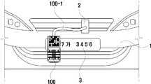
- FIG. 2is a conceptual diagram showing that the charging connector of the present invention is mounted on an electric vehicle.
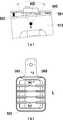
- FIG. 3is a perspective view showing the charging connector of the present invention.
- FIG. 4is a perspective view of the charging connector of the present invention as viewed from a different point in time from FIG. 3.
- FIG. 5is a front view of the charging connector of the present invention.
- FIG. 6is a perspective view showing a charging connector of a modification of the present invention.
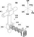
- FIG. 7is a perspective view showing the charging robot of the present invention.
- FIG. 8is a perspective view of the charging robot of the present invention as viewed from a different point in time from FIG. 7.
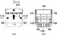
- FIG. 9(a)is a plan view showing the charging robot of the present invention
- FIG. 9(b)is a bottom view showing the charging robot of the present invention.
- FIG. 10is a side sectional view showing the charging robot of the present invention.
- FIG. 11is a perspective view showing a docking device of the present invention.
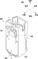
- FIG. 12is an exploded perspective view showing a docking socket of the present invention.
- FIG. 13(a)is a plan view showing attitude control of the docking socket of the present invention
- FIG. 13(b)is a front view showing the docking socket of the present invention.
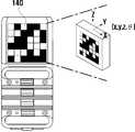
- FIG. 14(a)is a perspective view showing a state where the charging connector and docking socket of the present invention are docked
- FIG. 14(b)is a perspective view showing a state where the charging connector and docking socket of the present invention are separated.
- the spatially relative terms “below”, “beneath”, “lower”, “above”, “upper”, etc.,are as shown in the figure. It can be used to easily describe a correlation between a component and other components.
- the spatially relative termsshould be understood as terms including different directions of components in use or operation in addition to the directions shown in the drawings. For example, if a component shown in the drawing is turned over, a component described as “below” or “beneath” of another component will be placed “above” of the other component. Can.
- the exemplary term “below”can include both the directions below and above.
- the componentcan also be oriented in other directions, so that spatially relative terms can be interpreted according to the orientation.
- one side and the other side of the z-axis shown in the drawingmay be defined in the front-rear direction.
- the direction of the arrow on the z-axismay be defined rearward, and the direction opposite to the direction of the arrow on the z-axis may be defined forward.
- the frontmay be mixed with "the direction of autonomous driving of the charging robot", and the front may be defined by "the direction of autonomous driving of the charging robot".
- one side and the other side of the x-axis shown in the drawingmay be defined in the left-right direction.
- the arrow direction of the x-axismay be defined as the right side
- the opposite direction of the arrow direction of the x-axismay be defined as the left axis.
- one side and the other side of the y-axis shown in the drawingmay be defined in the vertical direction.
- the direction of the arrow on the y-axiscan be defined as the upper side
- the direction opposite to the direction of the arrow on the y-axiscan be defined as the lower side.
- the vertical directionmay be mixed with the "vertical direction”.
- FIG. 1is a conceptual diagram showing the process of charging the electric vehicle charging the electric vehicle in the charging station of the present invention
- Figure 2is a conceptual diagram showing that the charging connector of the present invention is mounted on the electric vehicle
- Figure 3is the present invention It is a perspective view showing a charging connector
- FIG. 4is a perspective view of the charging connector of the present invention viewed from a different point of view
- FIG. 5is a front view of the charging connector of the present invention
- FIG. 6is a charging connector of a modification of the present invention 7 is a perspective view showing the charging robot of the present invention
- FIG. 1is a conceptual diagram showing the process of charging the electric vehicle charging the electric vehicle in the charging station of the present invention
- Figure 3is the present invention It is a perspective view showing a charging connector
- FIG. 4is a perspective view of the charging connector of the present invention viewed from a different point of view
- FIG. 5is a front view of the charging connector of the present invention
- FIG. 6is a charging connector of
- FIG. 8is a perspective view of the charging robot of the present invention viewed from a different point of view
- FIG. 9(a)shows the charging robot of the present invention
- 9(b)is a bottom view of the present charging robot
- FIG. 10is a side sectional view showing the charging robot of the present invention
- FIG. 11is a perspective view showing the docking device of the present invention
- FIG. 12is An exploded perspective view showing the docking socket of the present invention
- FIG. 13(a)is a plan view showing attitude control of the docking socket of the present invention
- FIG. 13(b)is a front view showing the docking socket of the present invention.
- (A)is a perspective view showing a state where the charging connector and docking socket of the present invention are docked
- FIG. 14(b)is a perspective view showing a state where the charging connector and docking socket of the present invention are separated.
- the charging robot 1000 of the present inventionmay perform a function of charging the parked electric vehicle 1.
- the electric vehicle 1may be a vehicle that is moved by being provided with driving power by a battery engine, and further includes a hybrid vehicle that is moved by being supplied by driving power by a battery engine and an internal combustion engine.
- the userparks the electric vehicle 1, mounts the charging connector 100 on the license plate 3 of the electric vehicle 1, and then charges the charging connector 100 by the cable 100-1. It can be electrically connected to the charging port 2 of (1) (see Fig. 1 (a), Fig. 2).
- the charging robot 1000 of the present inventionmay be docked directly to the charging port of the electric vehicle 1, and in this case, the charging connector 100 may be omitted.
- the charging port 2 of the electric vehicle 1 and the charging connector 100may have substantially the same structure.
- the charging port 2 of the electric vehicle 1may be provided from the production and production stage of the electric vehicle 1, or alternatively, the user may be provided by remodeling the charging port 2 of the electric vehicle 1. have.
- the usermay use the user device 10 to transmit an order signal to call the charging robot 1000 of the present invention to a central server (robot management company server, parking lot management server, etc.).
- the user device 10may include one or more of a telecommunication device such as a smart phone, a tablet, a PDA, a laptop, and a remote controller, but is not limited thereto.
- the parking lotmay be divided into a plurality of parking areas (on the other hand, a plurality of parking areas may have mutually overlapping parts), and a plurality of parking areas with smart tags (eg, NFC tags; Near field communication Tag) may be provided (eg, attached to a pillar).
- the usercan transmit the order signal to the central server by selecting the NFC tag located in the parking area of the electric vehicle 1 using the user device 10, but the order signal of the present invention is not limited thereto.
- the parking lotmay be mapped to the central server based on the drawing of the building.
- the parking area of the electric vehicle 1can be specified in the mapped parking lot by the user's order signal (by processing the user's order signal).
- the central servermay issue a control command to the charging robot 1000 so that the charging robot 1000 moves to the parking area of the electric vehicle 1.
- the charging robot 1000 of the present inventioncan move from the standby position to the parking area of the electric vehicle 1 (a wide range including the location where the electric vehicle is parked) by autonomous driving (FIG. 1). (b)(2-1)).
- the charging robot 1000 of the present inventionsenses a "feature point" by the position sensors 820 and 830 while moving in autonomous driving, and is related to the position of the charging connector 100 (or charging port of an electric vehicle). It is possible to generate location information, and accordingly, it is possible to stop autonomous driving, change the posture, and then drive to the vicinity of the electric vehicle 1.
- the charging robot 100has a charging connector 100 (or electricity) in the direction of withdrawal (rear) of the docking device 400 according to location information related to the position of the charging connector 100 (or charging port of an electric vehicle). After changing the posture so that it is aligned with the direction in which the charging port of the vehicle is located, the electric vehicle 1 may move in a straight line to the vicinity.
- the "feature points”can be located in various places in various numbers and shapes.
- the "feature point”may be a feature point (not shown) of a parking area located in a parking area, and a charging connector 100 located in a charging connector 100 (or charging port of an electric vehicle) or a charging port of an electric vehicle ) May be a feature point 140, but the location of the "feature point" of the present invention is not limited thereto.
- the "feature point"may have a shape such as a smart code and may be identified as a two-dimensional image by the location sensors 820 and 830, or may be identified as three-dimensional depth information by the location sensors 820 and 830 by having a specific shape. (820,830) may be identified by communicating with a specific electronic signal (eg, a beacon), but is not limited thereto.
- a specific electronic signaleg, a beacon
- the "location information related to the location of the charging connector 100 (or charging port of the electric vehicle)"is processed by a specific algorithm and the location (coordinates) of the charging connector 100 (or charging port of the electric vehicle) in the space of the parking lot. ) Can be interpreted as a concept encompassing all information that can be derived (calculated), and is not limited to the position (coordinate) of the charging connector 100 (or charging port of an electric vehicle) itself.
- the charging robot 1000 of the present inventionmay be provided with a remote location sensor 820, the remote location sensor 820 is a feature (not shown) of the parking area and charging connector 100; or charging of the electric vehicle At least one of the feature points 140 of the former) can be sensed.
- the withdrawal direction of the docking device 400 of the charging robot 1000is the charging connector 100; or the charging port of the electric vehicle After changing the posture so that it is aligned with the direction in which the) is located, it can move in a straight run to the vicinity of the electric vehicle 1 (see (2-2) of FIG. 1(b)).
- the posturemay be changed so that the rear of the charging robot 1000 faces the charging connector.
- the charging robot 1000 of the present inventioncan be charged to the electric vehicle 1 after being docked to the charging connector 100 (or charging port of an electric vehicle) by driving the docking device 400. .
- the charging robot 1000 of the present inventionmay be provided with a short-range position sensor 830, the short-range position sensor 830 in the vicinity of the electric vehicle 1, the charging connector 100; or charging of the electric vehicle The feature point 140 of the former) may be sensed.
- the docking device 400 of the charging robot 1000 of the present inventionis a robot arm 410 that is linearly driven in three axes and a charging connector 100 disposed on the robot arm 410 or a charging port of an electric vehicle. ) May include a docking socket 500 that is docked.
- the docking device 400moves the charging robot 1000 to the vicinity of the electric vehicle 1, and then generates the “position” generated by the feature point 140 of the charging connector 100 (or charging port of the electric vehicle). Information".
- the robot arm 410is driven according to the "location information" of the charging connector 100 (or charging port of the electric vehicle), so that the docking socket 500 is connected to the charging connector 100 (or charging port of the electric vehicle). It can be docked.
- the charging robot 1000 of the present inventiondocks the electrical energy of the electrical energy storage device 300 with a docking socket 500, a charging connector 100, a cable 100-1, and a charging port of the electric vehicle 1
- the electric vehicle 1can be charged through the process of transferring it to the electric vehicle 1 through (2) (see (c) of FIG. 1 ).
- the charging robot 1000 of the present inventionmoves to the charging station 20 shown in Fig. 1(d), and the charging connector 100 It can be charged by being docked to the charging station connector 20-1 in the same way as it is docked to.
- the charging station connector 20-1 and the charging connector 100may have substantially the same structure.
- the charging robot 1000 of the present inventioncan move from the standby position to the parking area of the electric vehicle 1 by autonomous driving.
- the parking region of the electric vehicle 1is a user's order signal. It may be a region specified in the parking lot mapped by.
- the charging robot 1000changes the posture according to the "location information” and then the electric vehicle in the parking area of the electric vehicle 1. It can move to the vicinity of (1), and the docking device 400 can be driven by driving according to “location information”.
- the remote location sensor 820may generate “location information” when the charging robot 1000 moves to the vicinity of the electric vehicle 1, and the short-range location sensor 830 may be equipped with the docking device 400. When driving, it is possible to generate "location information”.
- the process of charging the electric vehicle 1 by the charging robot 1000 of the present inventionis not limited thereto.
- the charging robot 1000 of the present inventionmoves to autonomous driving to the vicinity of the electric vehicle 1 by the user's order signal, and then docks the device according to the location information generated by the short-range position sensor 830 ( 400) may be driven and docked in the charging connector 100 (or charging port of an electric vehicle).
- the charging connector 100 of the present inventioncan be electrically connected to the charging port 2 of the electric vehicle 1 by a cable 100-1, and the license plate 3 of the electric vehicle 1 It can be mounted on and fixed (see FIG. 2).
- the docking socket 500 of the charging robot 1000is docked to transfer electrical energy of the electrical energy storage device 300 to the electric vehicle 1.
- the charging connector 100 of the present inventionmay include a case 110, a plurality of connector guides 120, one or more connector electrodes 130, a feature point 140, and a plurality of hooks 150.
- the case 110 of the charging connector 100is a member that forms the appearance of the charging connector 100, and may be manufactured by injection molding of synthetic resin.
- the plurality of connector guides 120may have a shape corresponding to male and female coupling with the socket guide 520 of the docking socket 500. Therefore, the plurality of connector guides 120 may be formed to protrude, or may be formed to be recessed, and some may be formed to be protruded and some to be recessed.
- the plurality of connector guides 120When the plurality of connector guides 120 are docked, the plurality of connector guides 120 may be accommodated in the plurality of socket guides 520 of the docking socket 500, and correctly guide the path in which the docking socket 500 is docked. can do.
- the charging robot 1000 of the present inventioncan dock the docking socket 500 to the charging connector 100 by linear driving of the robot arm 410 (dock driving). If, if the charging robot 1000 of the present invention can also perform up to three-axis rotation driving of the robot arm 410, the attitude of the docking socket 500 according to the attitude of the charging connector 100 (slight tilting, etc.) It will be possible to perform docking without error of one value by precisely controlling the.
- the charging robot 1000 of the present inventionby providing a plurality of connector guides 120, when docking, the charging robot 1000 of the present invention does not precisely control the attitude of the docking socket 500, which is caused by fine control. By compensating for the error, the docking socket 500 of the charging robot 1000 can be guided stably.
- the charging connector 100 of the present inventioneven if the docking path of the docking socket 500 of the charging robot 1000 is finely deviated from the normal path to proceed with the docking, the docking socket by the plurality of connector guides 120 ( 500) so that docking can be stably performed.
- each of the plurality of connector guides 120may have an arrangement in which they are spaced apart from each other in the vertical direction (y-axis).
- the plurality of socket guides 520 of the docking socket 500are spaced apart from each other in the vertical direction.
- the plurality of connector guides 120may include a connector guide 121 positioned at the top, a connector guide 122 positioned at the bottom, and a connector guide 123 positioned in the middle.
- the number of the connector guides 123 located in the middlemay be adjusted according to the number of the plurality of connector guides 120.
- the connector guide 121 located at the top and the connector guide 122 located at the bottommay be formed to protrude more than the connector guide 123 located in the middle (in the form of a recess, the connector guides at the top and bottom are further recessed). .
- the maximum protruding length of the protruding end of the connector guide 121 located at the top and the connector guide 122 located at the bottommay be longer than the maximum protruding length of the protruding end of the connector guide 123 located in the middle.
- the connector guide 121 located at the top and the connector guide 122 located at the bottommay be thicker than the connector guide 123 located in the middle.
- the maximum length perpendicular to the projecting direction of the connector guide 121 located at the top and the connector guide 122 located at the bottommay be longer than the maximum length perpendicular to the projecting direction of the connector guide 123 located in the middle.
- the reason for differently setting the shape of the plurality of connector guides 120is that the connector guide 121 located at the top and the connector guide 122 located at the bottom are vertically positioned among the plurality of connector guides 120 ( y-axis) as a connector guide located on the outermost side, the docking socket of the charging robot 1000 is involved in the posture control of the docking socket 500 of the charging robot 1000 to the x-axis for the first time, The purpose is to guide the entirety of the 500) into a predetermined frame of the plurality of connector guides 120.
- At least one of the connector guide 121 located at the top and the connector guide 122 located at the bottomis in contact with the contact sensor 560 of the docking socket 500, so that the contact sensor 560 generates a "contact signal”. You can do it.
- Contact signalis a signal that the docking is completed, the "contact signal” in the contact sensor 560 of the docking socket 500 may be generated and then charging is started.
- each of at least some of the plurality of connector guides 120is located below the first inclined portion 120-1 and the first inclined portion 120-1 inclined downward toward the protruding direction. It may include a second inclined portion (120-2) inclined upward toward the direction.
- the plurality of connector guides 120are spaced apart from the plurality of socket guides 520 of the docking socket 500 according to the length of the docking socket 500 of the charging robot 1000 being drawn out (although described later). By narrowing step by step, the docking socket 500 of the charging robot 1000 can be guided naturally.
- each of at least some of the plurality of connector guides 120has a third inclined portion 120-3 inclined to the left toward a protruding direction (in a recessed direction in a recessed form), Located on the left side of the third inclined portion (120-3) may include a fourth inclined portion (120-4) inclined to the right toward the protruding direction. Meanwhile, the third inclined portion 120-3 and the fourth inclined portion 120-4 may be disposed between the first inclined portion 120-1 and the second inclined portion 120-2. It is not limited.
- each of the plurality of connector guides 120may be rounded at least partially. As a result, the plurality of connector guides 120 may be prevented from being worn by friction portions by rounded corners in the process of being accommodated in the plurality of socket guides 520 of the docking socket 500.
- each of the plurality of connector guides 120may have a shape extended in the left-right direction (x-axis) (having a length in the left-right direction).
- the plurality of socket guides 520 of the docking socket 500are in the left-right direction (x-axis).
- the one or more connector electrodes 130may be disposed adjacent to the plurality of connector guides 120 so as not to overlap with the feature points 140 in the front-rear direction. One or more connector electrodes 130 may be disposed between the plurality of connector guides 120. When docking, the one or more connector electrodes 130 may be electrically connected to one or more socket electrodes 530 of the docking socket 500.
- Each of the one or more connector electrodes 130may be formed to extend in a left-right direction (x-axis), and may include a first connector electrode 131 and a second connector electrode 132 adjacent in a vertical direction (y-axis). Can be. Accordingly, when docking, one or more socket electrodes 530 of the docking socket 500 may be drawn between the first connector electrode 131 and the second connector electrode 132 of the one or more connector electrodes 130. As a result, the one or more connector electrodes 130 compensate for that the robot arm 410 of the charging robot 1000 does not perform posture control driving, like the plurality of connector guides 120, and one or more socket electrodes 530 Can guide.
- the curvature of the first connector electrode 131 and the second connector electrode 132may be formed in opposite directions, so that physical resistance is generated by friction when the one or more socket electrodes 530 are drawn in. It can prevent abrasion.
- ends of the plurality of connector guides 120 protruding from the one or more connector electrodes 130may not protrude beyond the ends of portions protruding from the plurality of connector guides 120.
- the one or more connector electrodes 130may be coupled to one or more socket electrodes 530 of the docking socket 500 after the docking socket 500 is guided by the plurality of connector guides 120.
- one or more connector electrodes 130may include a connector charging electrode (not shown) and a connector signal electrode (not shown).
- the connector charging electrodecan be electrically connected to a docking charging electrode (not shown) of the docking socket 500, and the connector signal electrode is coupled to a docking signal electrode (not shown) of the docking socket 500.
- the connector charging electrodemay be an electrode used as a channel for charging
- the connector signal electrodemay be an electrode generating a signal to confirm whether or not docking. Therefore, when docking, a "connection signal" may be generated (or simultaneously) through the connector signal electrode and the docking signal electrode, and then charging may be started through the connector charging electrode and the docking charging electrode.
- One or more connector electrodes 130 of the modified example of the charging connector 100 of the present inventionmay be provided in various forms.
- the one or more connector electrodes 130are five pin-shaped electrodes or five pin holes. It may be an electrode of the form (5 pin electrode, 5 pin hole electrode) (having a male and female fastening form with the docking electrode, for example, when the connector electrode is in the form of a pin, the docking electrode may be in the form of a pin hole, and vice versa)
- somemay be in the form of a pin and the rest may be in the form of a pin hole), of which four electrodes may be connector charging electrodes and one electrode may be a connector signal electrode, but is not limited thereto.
- the feature point 140is sensed by the position sensors 820 and 830 of the charging robot 1000 to provide "location information" for the charging connector 100 (or charging port of an electric vehicle) to the charging robot 1000.
- the feature point 140may be disposed adjacent to the plurality of connector guides 120.
- the feature point 140may be disposed on the upper side of the plurality of connector guides 120 (ie, the upper side of the connector guide 121 located at the top).
- the feature point 140may be used as the feature point 140, regardless of whether they are contact or non-contact.
- a smart code or the likemay be used as the feature point 140.
- the feature point 140is formed on a charging connector 100 (or charging port of an electric vehicle) on a two-dimensional plane, and the charging robot 1000 It is possible to provide "location information" for the charging connector 100 (or charging port of the electric vehicle) in 3D coordinates.
- the "location information"may be data (coordinate values of the charging connector on the three-dimensional coordinates) for the distance d and the angle ⁇ between the location sensors 820 and 830 and the charging connector 100.
- the plurality of hooks 150may perform a function of mounting the charging connector 100 on the license plate 3 of the electric vehicle 1.
- the mounting point of the charging connector 100 of the present inventionis not limited to the license plate 3 of the electric vehicle 1. That is, the charging connector 100 of the present invention may be mounted on various parts of the electric vehicle 1, for example, may be mounted on the front bumper of the electric vehicle 1.
- the plurality of hooks 150may be located on opposite sides of the plurality of connector guides 120 in the case 110 of the charging connector 100. At least some of the plurality of hooks 150 may be located on the upper side, and the other portions may be located on the lower side. That is, the plurality of hooks 150 may be spaced apart in the vertical direction (y-axis).
- the hook located on the upper side of the plurality of hooks 150may be movable in the vertical direction, and the hook located on the lower side of the plurality of hooks 150 may be pivot driven.
- the charging connector 100adjusts the separation distance of the plurality of hooks by moving the hook located on the upper side of the plurality of hooks 150 in the vertical direction according to the height of the license plate 3, and the plurality of hooks 150
- the upper and lower frames of the license plate 3can be clamped by pivoting the hook located at the lower middle of the hook, thereby being mounted on the license plate 3.
- the plurality of hooks 150 of the charging connector 100 of the present inventionincludes a first hook 151 and a second hook 152 positioned on the upper side, and a third hook 153 positioned on the lower side.
- the usercan move the first hook 151 and the second hook 152 in the vertical direction according to the height of the license plate 3, and then the third hook 153 in a state in close contact with the license plate 3
- the charging connector 100may be mounted on the license plate 3.
- the charging connector 2000 of the modified example of the present inventiondoes not need the cable 100-1, and does not need to be mounted on the license plate 3, and charges the electric vehicle 1 It can be docked directly to the sphere 2 (see FIG. 6; simple).
- a plurality of hooks 150 of the charging connector 1000 of the present inventionmay be omitted.
- the charging connector 2000 of the modification of the present inventionmay include other configurations of the charging connector 1000 of the present invention in addition to the plurality of hooks 150, in this case, of the charging connector 1000 of the present invention The configuration can be inferred and applied.
- the charging connector 2000 of the modification of the present inventionmay further include a sub-connector 2200 and a hinge link 2300.
- the sub-connector 2200may be docked to the charging port 2 of the electric vehicle 1, and the hinge link 2300 may connect the case 2100 and the sub-connector 2000 to enable hinge driving. Therefore, the charging connector 2000 of the modified example of the present invention can be changed in posture while docked with the charging port 2 of the electric vehicle 1.
- the hinge connector 2300may change the posture of the case 2100 based on various axes, and may be replaced with various types of connectors such as spherical connectors.
- the charging robot 1000 of the present inventionincludes a case 200, an electric energy storage device 300, a docking device 400, a base 600, a mobile device 700, a sensing device 800, and an emergency button 900. , A bumper 1100 and an electronic control device (not shown).
- the case 200may be configured to form the appearance of the charging robot 1000. Meanwhile, a shutter 210 may be disposed behind the case 200 of the charging robot 1000. The shutter 210 is selectively opened during docking driving and charging of the charging robot 1000 to provide an opening portion so that the docking device 400 is drawn out.
- a first compartment 201 in which the electrical energy storage device 300 is accommodated and a second compartment 202 in which the docking device 400 is accommodatedmay be formed in the case 200.
- the first compartment 201may be disposed in front of the second compartment 202, and accordingly, the relatively heavy electric energy storage device 300 is located in the front and the relatively light weight docking device. 400 is located at the rear, the overall center of gravity of the charging robot 1000 may be biased forward.
- the electric energy storage device 300may store electric energy for charging the electric vehicle 1.
- the electrical energy storage device 300may be built in the case 200. In this case, the electrical energy storage device 300 may be disposed in front of the docking device 400. Meanwhile, the electrical energy storage device 300 may be a rechargeable secondary battery.
- the docking device 400may be docked with the charging port 2 or the charging connector 100 of the electric vehicle 1 to be configured to charge the electric vehicle 1. To this end, the docking device 400 may be electrically connected to the electrical energy storage device 300, and may include a robot arm 410 and a docking socket 500.
- the robot arm 410may drive linearly in three axes (x, y, and z axes).
- a docking socket 500may be disposed on the robot arm 410, and the docking socket 500 moves according to the docking driving of the robot arm 410, so that the charging port 2 or charging connector of the electric vehicle 1 ( 100).
- the robot arm 410is a first rail 411, a second rail 412, an arm part 413, a first robot arm drive part 414, a second robot arm drive part 415, and a third for driving the three axes.
- 3may include a robot arm driving unit 416.
- the first rail 411may extend in the left-right direction (x-axis), and the second rail 412 is left-right direction (x-axis) along the first rail 411 by the first robot arm driver 414. Can move straight.
- the second rail 412may extend in a vertical direction (y-axis; up-down direction), and the arm portion 413 is vertically along the second rail 412 by the second robot arm driving unit 415 (y-axis). ) To move straight.
- the arm part 413may be linearly moved in the front-rear direction (z-axis) by the third robot arm driving part 416.
- first rail 411 and the second rail 412may be provided in the form of a ball screw or lead screw, and the arm portion 413 may be provided in the form of an “x-link lift”.
- various types of electric motors (for example, step motors) or hydraulic machinesmay be used as the first robot arm driving unit 414, the second robot arm driving unit 415, and the third robot arm driving unit 416.
- the reason for providing the first rail 411 and the second rail 412 in the form of a ball screw or a lead screwis to stably support the arm portion 413 and precisely move it.
- the reason why the arm part 413 is provided in the form of an “x-link lift”is that it does not require much storage space when folded (reduced the length of the charging robot's length) when compared with other drawing devices, and can secure a sufficient drawing length when unfolded. Because.
- the first robot arm driving unit 414 and the second robot arm driving unit 415are first driven (x, y-axis driving), so that the docking socket in the two-dimensional coordinate (xy coordinate) ( 500) may be aligned with the charging port 2 or the charging connector 100 of the electric vehicle 1.
- the third robot arm driving unit 416is driven (z-axis driving), the arm unit 413 is pulled out through the rear (direction of the z-axis arrow), the docking socket 500 of the electric vehicle (1)
- the charging port 2 or the charging connector 100may be docked.
- the electrical energy storage device 300may be disposed at the rear, and the docking device 400 may be disposed in the front, and in this case, the arm 413 may be pulled forward. have.
- the robot arm 410 of the driving device 400has been described above, and a detailed description of the docking socket 500 will be described later.
- the base 600may perform one of forming a lower surface (lower plate) of the case 200 and supporting the case 200. That is, the base 600 may be a member integrally formed with the case 200 or may be disposed under the case 200 as a separate member from the case 200 to support the case 200. Furthermore, the base 600 may be a member composed of a single layer, or may be a member that is stacked to form a plurality of layers.
- the base 600may include a main body 610 that overlaps the case 200 in the vertical direction (y-axis) and a protrusion 620 that does not overlap the case 200 and the vertical direction (y-axis).
- the protrusion 620may protrude rearward from the body 610 of the base 600.
- the protrusion 620may be drawn under the body of the electric vehicle 1.
- the center of gravity of the charging robot 1000 of the present inventionis positioned to be deflected forward by the relatively heavy energy storage device 300, accordingly, the base 600 is projected rearward to charge The robot 1000 was prevented from being easily collapsed during driving and charging (especially, to fall forward).
- the portion 611 that overlaps with the first compartment 201 in the body 610 of the base 600 in the vertical directionoverlaps with the second compartment 202 in the body 610 of the base 600. It may be located above the portion 612. That is, a step may be formed in the main body 610 of the base 600.
- the docking device 400 accommodated in the second compartment 202is relatively lower than the first compartment 201 in order to be docked with the charging port 2 or the charging connector 100 of the electric vehicle 1. It could be because it needs to be located.
- the main driving direction of the charging robot 1000is the front (autonomous driving direction; however, after changing the posture, the vehicle travels backward)
- the diameter of the charging robot 1000needs to be efficiently transmitted. By arranging the large wheel, it may be because the first compartment 201 moves upward as much as the placement space occupied by the wheel having a large diameter (or as much as the accommodation space of the wheel driving unit).
- the main body 610 of the base 600is made from the body 610 of the base 600 and the portion 611 overlapping the first compartment 201 in the vertical direction from the body 610 of the base 600.
- a reinforcing frame 610-1may be formed to obliquely connect the part 612 overlapping the two compartments 202 in the vertical direction.
- the reinforcing frame 610-1is formed to be inclined downward toward the portion 612 that overlaps with the second compartment 202 in the vertical direction from the body 610 of the base 600, and is relatively positioned on the upper side.
- the second compartment 202 having a heavy weightmay be stably supported.
- the mobile device 700may be configured to move the charging robot 1000 of the present invention.
- the mobile device 700may include a first wheel 710, a second wheel 720, a third wheel 730, a fourth wheel 740 and a wheel driver 750.
- the first wheel 710 and the second wheel 720may be driving wheels driven by the wheel driving unit 750, and the third wheel 730 and the fourth wheel 740 may be the first wheel 710 and the first wheel 710. It may be a driven wheel driven to drive the two-wheel (720).
- the first wheel 710 and the second wheel 720are the main body 610 of the base 600 It can be placed in front to generate moving power.
- the third wheel 730 and the fourth wheel 740are disposed on the protrusion 620 of the base 600 to support the base 600 from the rear, and the first wheel 710 and the second wheel 720 ).
- the first wheel 710may be located on the right side of the edge of the body 610 of the base 600
- the second wheel 720may be located on the edge of the body 610 of the base 600. It may be located on the left side
- the third wheel 730may be located on the right side of the edge of the protrusion 620 of the base 600
- the fourth wheel 740 of the protrusion 620 of the base 600It can be located on the left side of the edge.
- first wheel 710 and the second wheel 720which are driving wheels, may have a larger diameter than the third wheel 730 and the fourth wheel 740, which are driven wheels.
- the protrusion 620 of the base 600may be drawn under the body of the electric vehicle 1 when the charging robot 1000 of the present invention moves adjacent to the electric vehicle 1. have.
- the top of the protrusion 620 from the bottom of the third wheel 730 and the fourth wheel 740The length up to may be shorter than the length of the minimum ground clearance of the electric vehicle 1.
- the length from the bottom of the third wheel 730 and the fourth wheel 740 to the top of the protrusion 620may vary according to the minimum ground height according to laws and regulations of individual countries, for example, may be 15 cm or less.
- the sensing device 800may include an obstacle sensor 810, position sensors 820, 830 and a bumper sensor (not shown).
- the obstacle sensor 810may be disposed in the case 200 and sense an obstacle.
- the obstacle sensor 810may mainly sense an obstacle when moving.
- the obstacle sensor 810moves when the charging robot 1000 moves to the parking area of the electric vehicle 1 by autonomous driving and moves linearly (driving after a posture change) adjacent to the electric vehicle 1.
- An obstaclemay be detected in at least one of the cases.
- the charging robot 1000may move by stopping movement or changing a path after searching for another path.
- the obstacle sensor 810various types may be used for the obstacle sensor 810.
- a lidaran ultrasonic sensor, a 3D camera module, an RGBD camera module, and a kinect sensor may be used as the obstacle sensor 810, but is not limited thereto.
- the lidar 811may have a sensing area (scanning area) of two dimensions (xz plane), and an obstacle at a specific height (for example, approximately 60 cm from the ground; can fit a child's height). It is determined whether or not it exists, and it is possible to generate an effect that the sensing region is substantially three-dimensional.
- the obstacle sensor 810when different types of sensors are used as the obstacle sensor 810, there is an advantage of covering insufficient sensing conditions (eg, ambient illuminance, etc.) and the sensing area between each other (eg, lidar and ultrasonic wave). Combination of sensors).
- insufficient sensing conditionseg, ambient illuminance, etc.
- the sensing area between each othereg, lidar and ultrasonic wave.
- the obstacle sensor 810may be disposed on the front surface (front plate) of the case 200.
- the main sensing direction of the obstacle sensor 810see (1-1) in FIG. 9(a)
- a direction in which the sensing area gradually expands, a direction in which the center of the sensing area is formed, etc.may be an autonomous driving direction (front) of the charging robot 1000 in a plan view.
- the main sensing direction of the obstacle sensor 810is forward, and it is not that the obstacle sensor 810 cannot sense the left and right sides of the charging robot 1000.
- the obstacle sensor 810may also cover the left side (front left) and the right side (front right) of the charging robot 1000, so that the charging robot 1000 is adjacent to the electric vehicle 1 after changing the posture. Even when driving in the rear, it is possible to sense that obstacles appear on the left and right sides.
- the position sensors 820 and 830may sense the charging connector 100 (or charging port of the electric vehicle) to generate “location information” of the charging connector 100 (or charging port of the electric vehicle).
- the position sensors 820 and 830may be provided as a single type of sensor, and may include heterogeneous sensors, such as the remote position sensor 820 and the short-range position sensor 830, but are not limited thereto.
- the position sensors 820 and 830may perform sensing in various ways.
- at least one of a lidar, an ultrasonic sensor, a 3D camera module, an RGBD camera module, and a kinect sensormay be used as the position sensors 820 and 830, and the position sensors 820 and 830 are various types of “features It is possible to generate "location information" by sensing ", but is not limited thereto.
- the feature point 140may be imaged to generate "location information" (applied to the image analysis algorithm).
- the position sensors 820 and 830may include a long-range position sensor 820 and a short-range position sensor 830 according to the distance from the sensing target.
- the remote location sensor 820may generate “location information” when the charging robot 1000 moves autonomously and to the vicinity of the electric vehicle 1, and the short-range location sensor 830 ) May generate “location information” when the charging robot 1000 moves to the vicinity of the electric vehicle 1 and then the docking device 400 is driven.
- the remote location sensor 820senses at least one of a feature point (not shown) of the parking area and a feature point 140 of the charging connector 100 (or charging port of the electric vehicle) to charge the charging connector 100; or charging of the electric vehicle. It can generate location information related to the location of the old).
- the position of the charging connector 100may be derived by sensing the feature point 140 located in the charging connector 100 (or charging port of the electric vehicle), but unlike this, the electric vehicle 1 ) May be derived by processing and analyzing location information generated by sensing a feature point (not shown) located in the parking area (for example, sensing a QR code placed on a building structure in a parking area of an electric vehicle to sense the QR code) After obtaining the location coordinates, the distance between the building structure previously stored in the database and the expected parking location of the electric vehicle can be substituted from the coordinates of the QR code to derive the location of the charging connector).
- the far position sensor 820may be disposed on at least one of the right side (right side plate) and the left side (left side plate) of the case 200.
- the remote location sensor 820may include a first remote location sensor 821 and a second remote location sensor 822.
- the main sensing direction of the remote location sensor 820(see (1-2) and (1-3) of FIG. 9(a); for example, the direction in which the sensing area is gradually expanded, the center of the sensing area (camera module)
- the direction in which the optical axis) is formedmay be inclined with the autonomous driving direction (front) of the charging robot 1000 on a plan view.
- the main sensing direction of the remote location sensor 820may be perpendicular to the autonomous driving direction of the charging robot 1000 in a plan view.
- the charging robot 1000first performs autonomous driving toward the parking area of the electric vehicle 1 toward the front, and senses a characteristic point of the charging connector 100 (or charging port of the electric vehicle) during the autonomous driving process to charge the charging connector 100; Alternatively, the posture is changed so that the rear side faces the charging connector 100 (or the charging port of the electric vehicle) according to the "location information" of the charging port of the electric vehicle, and the vehicle is driven rearward to the charging connector 100; Charging port).
- the remote location sensorin order to sense the feature points of the charging connector 100 (or charging port of the electric vehicle) located on the left and right sides of the autonomous driving path of the charging robot 1000, the remote location sensor ( It is preferable that the main sensing direction of 820 is inclined or perpendicular to the autonomous driving direction (front) of the charging robot 1000.
- the first remote location sensor 821may be disposed on the right side (right side plate) of the case 200 of the charging robot 1000, and the main sensing direction is the autonomous driving direction of the charging robot 1000 on a plan view. It can be inclined to the right or vertical.
- the second remote position sensor 822may be disposed on the left side (left side plate) of the case 200 of the charging robot 1000, and the main sensing direction is the autonomous driving direction and the left side of the charging robot 1000 on a plan view. Can be sloped or vertical.
- the main sensing direction of the remote location sensor 820is inclined or perpendicular to the autonomous driving direction (front) of the charging robot 1000, and the remote location sensor 820 is a charging robot ( 1000) does not mean that it does not sense the front or rear.
- the emergency button 900may be arranged to be exposed from the case 200 of the charging robot 1000 to the outside.
- the emergency button 900may be operated by a touch operation of a user, a manager, or a nearby person, and when the emergency button 900 is touched, the movement of the charging robot 1000 is stopped and the electric vehicle 1 is charged. At least one of stopping things can be performed.
- the emergency button 900is charged in the case of an emergency (for example, when the charging robot maintains driving despite obstacles, when children are in danger of electric shock by approaching sockets and connectors during charging) It can be used when the operation of the robot 1000 is suddenly stopped.
- the emergency button 900may include at least one of the first emergency button 910 and the second emergency button 920, and the first emergency button 910 is the right side of the case 200 (right side panel). It may be located on the top, the second emergency button 910 may be located on the upper left side (left panel) of the case 200.
- the bumper 1100may be configured to perform a function of buffering when the charging robot 1000 is impacted. When the impact accident of the charging robot 1000 occurs, it is possible to prevent the charging robot 1000 from falling or the impact object being injured by the bumper 1100.
- the bumper 1100may be disposed on the base 600.
- the bumper 1100is supported by an elastic member, and may perform buffer driving by reciprocating movement in response to elastic deformation and restoration of the elastic member upon impact (air bumper).
- a bumper sensor(not shown) may be disposed on the bumper 1100 and sense the impact of the bumper 1100.
- the bumper sensorcan mainly sense the impact when moving.
- the bumper sensoris at least one of the case where the charging robot 1000 moves autonomously to the parking area of the electric vehicle 1 and when the vehicle moves in a straight line driving (driving after a posture change) adjacent to the electric vehicle 1.
- the impact of the bumper 1100can be sensed.
- the charging robot 1000may move by stopping the movement or changing a path after searching for another path.
- the charging robot 1000 of the present inventioncan detect the obstacle by the obstacle sensor 810 and the bumper sensor, and in the case of an impact with an obstacle in a sudden situation, can act as a buffer and detect the impact. , Accordingly, the movement may be stopped by changing the path after stopping the movement or searching for another path.
- the bumper 1100is disposed at the rear of the base 600, the first bumper 1100 for cushioning the rear impact, and the second bumper 1200 and the base 600 for cushioning the right impact disposed on the right side of the base 600.
- the first bumper 1100may be disposed on the protruding portion 620 of the base 600, and upon impact, may perform a buffer drive in the front-rear direction (z-axis).
- the second bumper 1200 and the third bumper 1300may be disposed on the main body 610 of the base 600, and may perform buffer driving in the left and right directions (x-axis) when impacted.
- the electronic control device(not shown) communicates with various components of the central server and the charging robot 1000 to process various signals and information, and accordingly, controls the components of the charging robot 1000 to charge the charging robot 1000 Can operate.
- the electronic control devicemay receive information on the runner area of the electric vehicle 1 from the central server, process it, and control the charging robot 1000 to autonomously drive to the parking area of the electric vehicle 1. have.
- the electronic control deviceprocesses the "location information" related to the location of the "obstacle information” generated by the sensing device 600 and the charging connector 100 (or charging port of the electric vehicle), and accordingly, the docking device 400 ) And the mobile device 700 to control the docking driving, driving stop and route re-search function.
- the electronic control devicereceives the touch signal of the emergency button 900, and accordingly, controls the electric energy storage device 300 and the mobile device 700 to perform a function of stopping charging or stopping driving. can do.
- the docking socket 500 of the present inventionmay constitute a “dock assembly” together with the charging connector 100 of the present invention.
- the docking socket 500is docked and driven by the robot arm 410 according to location information related to the position of the charging connector 100 (or charging port of the electric vehicle), thereby charging the connector 100 (or charging port of the electric vehicle). It may be a configuration docked in.
- the docking socket 500includes a case 510, a plurality of socket guides 520, one or more socket electrodes 530, a base 540, a posture control member 550, a contact sensor 560, and a short-range position sensor 830. ).
- the case 510may be a member that forms the external appearance of the docking socket 500, a plurality of socket guides 520 may be formed on the case 510, and one or more socket electrodes ( 530 may be disposed, the base 540 may be disposed at the rear (rear plate) of the case 510, and the posture control member 500 may be disposed between the case 510 and the base 540.
- the touch sensor 560may be disposed inside the rear surface (rear plate) of the case 510.
- a plurality of connector guides 420 of the charging connector 100may be accommodated. Accordingly, the plurality of socket guides 520 may perform a function of allowing the docking socket 500 to be precisely docked to the charging connector 100 (or charging port of an electric vehicle) without detachment when docking.
- the plurality of socket guides 520are matched (matched) with the plurality of connector guides 420 of the charging connector 100 (or charging port of an electric vehicle), so that the attitude of the docking socket 500 is not controlled. It can compensate for the occurrence of minute errors.
- the plurality of socket guides 520may have a corresponding shape so as to be combined with the plurality of connector guides 120 of the charging connector 100 (or charging port of an electric vehicle). Therefore, the plurality of socket guides 520 may be formed to protrude, or may be formed to be recessed, and some may be formed to protrude and some to be recessed.
- the plurality of socket guides 520are recessed in the front (in the opposite direction of the arrow on the z axis) in a form corresponding to the form in which the plurality of connector guides 420 of the charging connector 100 (or charging port of an electric vehicle) protrude. Can be formed.
- each of the plurality of socket guides 520may have an arrangement in which they are spaced apart from each other in the vertical direction (y-axis).
- the plurality of socket guides 520may include a socket guide 521 located at the top, a socket guide 522 located at the bottom, and a socket guide 523 located at the middle.
- the number of socket guides 523 located in the middlemay be adjusted according to the number of socket guides 520.
- the socket guide 521 located at the top and the socket guide 522 located at the bottomare more recessed than the socket guide 523 located in the middle (in the case of a protruding shape, the socket guides located at the top and bottom are formed to protrude more). Can be.
- the socket guide 521 located at the top and the socket guide 522 located at the bottommay be thicker than the socket guide 523 located at the middle.
- the plurality of socket guides 520accommodate a plurality of connector guides 120 spaced apart from each other in the vertical direction, thereby substantially As a result, the posture can be controlled.
- each of the plurality of socket guides 520may have a shape extended in a left-right direction (x-axis) (having a length in the left-right direction).
- the plurality of socket guides 520have a plurality of connector guides 120 having a form extending in the left-right direction (x-axis) By accepting, it is possible to exhibit an effect in which the posture is substantially controlled.
- the one or more docking electrodes 530may be disposed adjacent to the plurality of socket guides 520 so as not to overlap in the front-rear direction with the short-range position sensor 830. One or more docking electrodes 530 may be disposed between the plurality of socket guides 520. When docking, the one or more docking electrodes 530 may be electrically connected to one or more connector electrodes 130 of the charging connector 100 (or charging port of an electric vehicle). 14A shows a perspective view showing a state where the charging connector and the docking socket are docked.
- Each of the one or more docking electrodes 530may be formed to extend in a left-right direction (x-axis), and the first connector electrode of each of the one or more connector electrodes 130 of the charging connector 100 (or charging port of an electric vehicle) 131 (see FIG. 14(b)) and the second connector electrode 132 (see FIG. 14(b)).
- one or more docking electrodes 530may include a docking charging electrode (not shown) and a docking signal electrode (not shown).
- the docking charging electrodemay be electrically connected to the connector charging electrode (not shown) of the charging connector 100
- the docking signal electrodemay be electrically connected to the connector signal electrode of the charging connector 100.
- the docking charging electrodemay be an electrode used as a channel for charging
- the docking signal electrodemay be an electrode generating a signal for checking whether docking. Therefore, when docking, a "connection signal" may be generated (or simultaneously) through the docking signal electrode and the connector signal electrode, and then charging may be started through the docking charging electrode and the connector charging electrode.
- one or more docking electrodes 530 of a variation of the charging robot 1000 of the present inventionmay be provided in various forms.
- one or more docking electrodes 530may be five pin-shaped electrodes or five pin holes. It may be an electrode (5 pin electrode, 5 pin hole electrode) of the form (having a male and female fastening form with the connector electrode, for example, when the docking electrode is in the form of a pin, the connector electrode may be in the form of a pin hole, and vice versa)
- somemay be in the form of a pin and the rest may be in the form of a pin hole), of which four electrodes are docking charging electrodes and one electrode may be a docking signal electrode, but is not limited thereto.
- the base 540 of the docking socket 500may be disposed in front of the case 510 (in the direction opposite to an arrow in the z-axis).
- a short-range position sensor 830may be disposed on the base 540, and may be connected to the arm 413 of the robot arm 410.
- a printed circuit boardmay be provided on the base 540 of the docking socket 500, and an electrical energy storage device () may be provided by the printed circuit board of the base 540 of the docking socket 500.
- an electrical energy storage devicemay be provided by the printed circuit board of the base 540 of the docking socket 500.
- 300and one or more docking electrodes 530 may be electrically connected.
- a short-range position sensor 830may be disposed above the base 540 of the docking socket 500.
- the short-range position sensor 830captures the feature point 140 of the charging connector 100 (charging port of the electric vehicle) to “position information” regarding the position of the charging connector 100 (charging port of the electric vehicle). It may be a camera module that generates.
- the posture control member 540may be disposed between the case 510 of the docking socket 500 and the base 540 of the docking socket 500, and the posture of the case 510 of the docking socket 500 is variable. I can do it.
- the posture control member 540may control the posture of the case 510 of the docking socket 500 based on the y-axis (pivot drive that rotates a predetermined radius based on the y-axis).
- the posture control member 540may be elastically driven (elastically deformed) in the z-axis (front-rear direction), and may include a pair of elastic bodies 550 spaced apart from each other in the x-axis (left-right direction). That is, the pair of elastic bodies 550 may include a first elastic body 551 and a second elastic body 552 that are elastically deformed in the z-axis, and the first elastic body 551 may be disposed on the right side. The two elastic bodies 552 may be disposed on the left side.
- the posture control member 540may further include a torsion spring (not shown) to guide y-axis yaw control of the case 510.
- the torsion springmay be disposed between the first elastic body 551 and the second elastic body 552.
- the posture control member 540may compensate for a minute error caused when the robot arm 410 is not yaw-controlled in the y-axis.
- the plurality of socket guides 520can obtain substantially the same effect as the x-axis pitch control by the stacking arrangement spaced apart from each other in the vertical direction (y-axis), and the plurality of socket guides ( 520) and one or more docking electrodes 530 may have substantially the same effect as the z-axis roll control by having a long elongated shape, and the y-axis yaw control by the posture control member 540 This can achieve substantially the same effect.
- the contact sensor 560may be configured to contact the plurality of connector guides 120 of the charging connector 100 (or charging port of an electric vehicle) to sense that docking is completed.
- the contact sensor 560may include a first contact sensor 561 and a second contact sensor 562.
- the first contact sensor 561may be disposed on the bottom surface of the socket guide 521 located at the top, and may detect the contact of the connector guide 121 located at the top to generate a “contact signal”.
- the second contact sensor 562may be disposed on the bottom surface of the socket guide 522 located at the bottom, and detect the contact of the connector guide 122 located at the bottom to generate a “contact signal”.
- the charging robot 1000may start charging when the “contact signal” is generated in both the first contact sensor 561 and the second contact sensor 562 by an electronic control device (not shown). .
- the charging robot 1000starts charging in a state in which the docking of the docking socket 500 and the charging connector 100 (or a charging port of an electric vehicle) is not completed, the charging efficiency decreases and the docking socket 500 and charging A contact with a human body between the gaps of the connector 100 (or a charging port of an electric vehicle) may prevent an electric shock from occurring.
- the charging robot 1000starts charging when the "contact signal" occurs in both the first contact sensor 561 and the second contact sensor 562 located at the upper and lower portions, respectively, thereby docking the socket 500 It is possible to prevent charging from starting when the docking is not completed by inclining one of the overcharge connectors 100 (or a charging port of an electric vehicle) and contacting only one contact sensor.
- ock signal electrode (not shown)” and “connector signal electrode (not shown)” of modified examples of the charging connector 100 and charging robot 1000 of the present inventionhave substantially the same effect as the contact sensor 560.
- “dock signal electrode (not shown)” and “connector signal electrode (not shown)”may be provided simultaneously with the contact sensor 560 to implement a double safety device.
- the short-range position sensor 830may be used when the charging robot 1000 performs docking driving with the docking device 400 in the vicinity of the electric vehicle 1.
- the short-range position sensor 830senses the feature point 140 of the charging connector 100 (or charging port of the electric vehicle) to generate location information regarding the location of the charging connector 100 (or charging port of the electric vehicle). have.
- the short-range position sensor 830since the short-range position sensor 830 must precisely generate location information about the charging connector 100 (or charging port of an electric vehicle), unlike the remote location sensor 830, the parking area of the electric vehicle 1 It does not sense the feature point located in the, it is possible to generate location information by sensing only the feature point 140 disposed directly on the charging connector 100 (or charging port of an electric vehicle).
- the charging connector 100by capturing the feature point 140 of the charging connector 100 (or charging port of an electric vehicle). It may be a camera module that generates "location information" regarding the location of the old).
- the short-range position sensor 830may be a sensor for 3-axis linear driving of the docking device 400, and the robot arm 410 is a coordinate in which a charging connector 100 (or charging port of an electric vehicle) is located on three-dimensional coordinates. By moving the docking socket 500 toward, the docking socket 500 can be docked to the charging connector 100 (or charging port of an electric vehicle).
- the short-range position sensor 830may be disposed on the base 540 of the docking socket 500 located behind the case 510 of the docking socket 500 (more specifically, mounted on the printed circuit board of the base) ). Therefore, the short-range position sensor 830 may not overlap with the case 510 of the docking socket 500 in the vertical direction (y-axis), and accordingly, the charging connector 100 as the docking socket 500 is withdrawn or electricity Even if it approaches the feature point 140 of the charging port of the vehicle), it is possible to secure a certain distance to secure a focal length for focusing.
- the above-described configuration of the present inventioncan have various embodiments within a range that does not change the essential characteristics by those skilled in the art.
- some components of the charging connector 100may be provided in the docking socket 500 instead of the charging connector 100 (or charging port of the electric vehicle), or a part of the docking socket 500
- the configurationmay be provided on the charging connector 100 (or charging port of an electric vehicle) instead of the docking socket 500.
Landscapes
- Engineering & Computer Science (AREA)
- Mechanical Engineering (AREA)
- Robotics (AREA)
- Power Engineering (AREA)
- Transportation (AREA)
- Aviation & Aerospace Engineering (AREA)
- Radar, Positioning & Navigation (AREA)
- Remote Sensing (AREA)
- Physics & Mathematics (AREA)
- General Physics & Mathematics (AREA)
- Automation & Control Theory (AREA)
- Charge And Discharge Circuits For Batteries Or The Like (AREA)
Abstract
Description
Translated fromKorean본 발명은 전기자동차용 충전 로봇, 전기자동차 충전용 충전 커넥터, 도킹 소켓 및 도킹 어셈블리에 관한 것이다.The present invention relates to a charging robot for an electric vehicle, a charging connector for charging an electric vehicle, a docking socket and a docking assembly.
최근 들어, 화석 연료의 고갈, 환경 오염 등 각종 문제들로 인해서 이를 대체하기 위한 운송 수단에 대한 연구, 개발이 활발하게 이뤄지고 있다.Recently, due to various problems such as exhaustion of fossil fuels and environmental pollution, research and development of transportation means to replace them have been actively conducted.
그리고, 이미 상용화가 이루어진 운송 수단으로 전기자동차(Electric Vehicle)가 대표적이지만, 전기자동차가 등장할때마다 함께 언급되는 것이 전기차의 충전에 대한 것이다.In addition, although the electric vehicle is a typical transportation means that has already been commercialized, the electric vehicle is charged when the electric vehicle comes up.
아파트, 빌딩과 같은 건물 주차장의 모든 주차공간에 전기자동차 충전 장치를 설치하는 것은 현실적으로 너무 많은 비용이 들게 되며, 전기자동차가 아닌 자동차도 존재하는 점에서 비효율적이다.Installing an electric vehicle charging device in all parking spaces in a building parking lot, such as an apartment or building, is expensive in reality, and it is inefficient because there are vehicles other than electric vehicles.
그렇다면, 일부 주차공간에만 전기차 충전 장치를 설치하는 것이 대안이 될 수 있는데, 이 경우에는 주차공간이 남게되는 효율성의 문제점과 주차장에 전기차가 많이 진입할 경우 충전 장치가 모자랄 수 있다는 문제점이 발생하게 된다.If so, installing an electric vehicle charging device in only some parking spaces may be an alternative. In this case, there is a problem that the efficiency of the parking space remaining and the problem that the charging device may be insufficient when there are many electric vehicles entering the parking lot. do.
위와 같은 문제점들로 인해 대안으로 떠오른 것이 수동 이동식 충전 장치인데, 수동 이동식 충전 장치의 경우 사용자가 충전 스테이션에서 차량까지 이동식 충전 장치를 이동시켜야 하는 번거로움이 존재한다.Due to the above problems, a passive mobile charging device has emerged as an alternative. In the case of a manual mobile charging device, there is a problem that a user has to move the mobile charging device from a charging station to a vehicle.
상술한 바와 같이, 전기자동차의 사용자가 매년 급증하고 있는 상황에서 위와 같은 문제점들을 해결할 만한 대안은 제시되지 못하고 있다.As described above, in the situation where users of electric vehicles are rapidly increasing every year, there is no alternative to solve the above problems.
또한, 충전 로봇을 이용한 충전 자동화 시스템에서는 오류 발생을 최소화하기 위해, 충전 로봇의 도킹 소켓을 전기자동차의 충전구에 정밀하게 도킹시키는 것이 중요하며, 이를 위한 다양한 연구가 이뤄지고 있는 실정이다.In addition, in the charging automation system using the charging robot, in order to minimize the occurrence of errors, it is important to precisely dock the charging socket of the charging robot to the charging port of the electric vehicle, and various studies for this are being conducted.
본 발명이 해결하고자 하는 과제는 운전자의 간단한 오더만으로 전기자동차가 주차된 위치까지 자율주행으로 이동한 후, 전기자동차의 충전 커넥터에 자동 도킹되어 충전을 수행하는 충전 로봇을 제공하는 것이다.The problem to be solved by the present invention is to provide a charging robot that performs charging by being automatically docked to the charging connector of the electric vehicle after moving the electric vehicle to a parked position autonomously by a simple order of the driver.
또한, 본 발명이 해결하고자 하는 과제는 전기자동차 충전 로봇의 도킹 과정에서 오류가 발생하지 않도록, 충전 로봇의 도킹 소켓을 전기자동차의 충전구에 정밀하게 도킹시킬 수 있는 충전 커넥터와 도킹 소켓과 이를 포함하는 도킹 어셈블리를 제공하는 것이다.In addition, the problem to be solved by the present invention includes a charging connector and a docking socket capable of precisely docking the charging socket of the charging robot to the charging port of the electric vehicle, so as not to cause an error in the docking process of the charging vehicle of the electric vehicle. To provide a docking assembly.
본 발명이 해결하고자 하는 과제들은 이상에서 언급된 과제로 제한되지 않으며, 언급되지 않은 또 다른 과제들은 아래의 기재로부터 통상의 기술자에게 명확하게 이해될 수 있을 것이다.The problems to be solved by the present invention are not limited to the problems mentioned above, and other problems not mentioned will be clearly understood by those skilled in the art from the following description.
상술한 과제를 해결하기 위한 본 발명의 일 면에 따른 충전 로봇은 전기자동차를 충전하는 충전 로봇에 있어서, 케이스; 상기 케이스의 내부에 배치되는 전기에너지 저장장치; 상기 케이스의 내부에 배치되고, 상기 전기에너지 저장장치와 전기적으로 연결되고, 전기자동차의 충전구 또는 충전 커넥터에 도킹되는 도킹장치; 특징점을 센싱하여, 전기자동차의 충전구 또는 충전 커넥터의 위치와 관련된 위치 정보를 생성하는 위치 센서를 포함하고, 상기 충전 로봇은 상기 위치 정보에 따라 이동하고, 상기 도킹장치는 상기 위치 정보에 따라 구동할 수 있다.A charging robot according to an aspect of the present invention for solving the above-described problem is a charging robot for charging an electric vehicle, the case; An electrical energy storage device disposed inside the case; A docking device disposed inside the case, electrically connected to the electrical energy storage device, and docked with a charging port or charging connector of an electric vehicle; And a position sensor that senses a feature point and generates position information related to the position of the charging port or charging connector of the electric vehicle, the charging robot moves according to the position information, and the docking device is driven according to the position information can do.
상기 위치 센서는 특징점을 촬상하여 위치 정보를 생성할 수 있다.The position sensor may generate location information by imaging a feature point.
전기자동차의 주차영역은 사용자의 오더 신호에 의해 매핑된 주차장에서 특정되고, 상기 충전 로봇은 대기 위치에서 전기자동차의 주차영역까지 자율주행으로 이동할 수 있다.The parking area of the electric vehicle is specified in the parking lot mapped by the user's order signal, and the charging robot can move from the standby position to the parking region of the electric vehicle by autonomous driving.
상기 충전 로봇은 주차영역의 특징점과 전기자동차의 충전구 또는 충전 커넥터의 특징점 중 적어도 하나에 의해 생성된 위치 정보에 따라, 전기자동차의 주차영역에서 전기자동차의 인근까지 이동하고, 상기 도킹장치는 전기자동차의 충전구 또는 충전 커넥터의 특징점에 의해 생성된 위치 정보에 따라, 구동할 수 있다.The charging robot moves from the parking area of the electric vehicle to the vicinity of the electric vehicle according to the location information generated by at least one of the feature point of the parking area and the charging point of the electric vehicle or the charging connector, and the docking device It can be driven according to location information generated by a charging port of a vehicle or a feature point of a charging connector.
상기 충전 로봇은 상기 위치 정보에 따라, 상기 도킹장치의 인출 방향이 전기자동차의 충전구 또는 충전 커넥터가 위치한 방향과 정렬되도록 자세를 변경한 다음, 전기자동차의 인근까지 직선 주행으로 이동할 수 있다.The charging robot may change a posture such that the direction of the withdrawal of the docking device is aligned with the direction in which the charging port or charging connector of the electric vehicle is located according to the location information, and then move linearly to the vicinity of the electric vehicle.
상기 위치 센서는 상기 충전 로봇이 자율주행으로 이동하는 경우와 전기자동차의 인근까지 이동하는 경우 중 적어도 하나의 경우에 위치 정보를 생성하는 원거리 위치 센서와, 상기 도킹장치가 구동하는 경우에 위치 정보를 생성하는 근거리 위치 센서를 포함할 수 있다.The position sensor is a long-distance position sensor that generates position information in at least one of the case where the charging robot moves autonomously and moves to the vicinity of the electric vehicle, and the position information when the docking device is driven. It may include a short-range position sensor to generate.
상기 도킹장치는 3축으로 직선 구동하는 로봇 암과, 상기 로봇 암에 배치되고 전기자동차의 충전구 또는 충전 커넥터에 도킹되는 도킹 소켓을 포함하고, 상기 원거리 위치 센서는 상기 케이스에 배치되고, 상기 근거리 위치 센서는 상기 도킹 소켓에 배치될 수 있다.The docking device includes a robot arm that is linearly driven in three axes, and a docking socket disposed on the robot arm and docked with a charging port or charging connector of an electric vehicle, and the remote location sensor is disposed on the case, and the short distance The position sensor can be arranged in the docking socket.
상기 충전 로봇은 장애물을 센싱하는 장애물 센서를 더 포함할 수 있다.The charging robot may further include an obstacle sensor for sensing an obstacle.
상기 장애물 센서는 주된 센싱 방향이 평면도 상에서 자율주행 방향이고, 상기 원거리 위치 센서는 주된 센싱 방향이 평면도 상에서 자율주행 방향과 경사진 방향일 수 있다.The obstacle sensor may have a main sensing direction in an autonomous driving direction on a plan view, and the distal position sensor may have a primary sensing direction in a direction inclined with an autonomous driving direction on a plan view.
상기 충전 로봇은, 상기 케이스에 배치되고, 터치 동작에 의해 이동을 정지하는 것과 전기자동차를 충전시키는 것을 정지하는 것 중 적어도 하나를 수행하는 비상버튼; 상기 베이스에 배치되고, 충격 시 왕복 이동에 의해 완충 구동하는 범퍼를 더 포함할 수 있다.The charging robot includes an emergency button disposed on the case and performing at least one of stopping movement by charging and stopping charging the electric vehicle; It is disposed on the base, and may further include a bumper that is buffered by reciprocating movement during impact.
상기 충전 로봇은, 상기 범퍼에 배치되고, 상기 범퍼의 충격을 센싱하는 범퍼 센서를 더 포함할 수 있다.The charging robot may further include a bumper sensor that is disposed on the bumper and senses the impact of the bumper.
상기 충전 로봇은, 상기 케이스의 하면을 형성하는 것과 상기 케이스를 지지하는 것 중 적어도 하나를 수행하는 베이스; 상기 베이스의 하측에 배치되는 이동장치를 더 포함하고, 상기 베이스는 상기 케이스와 수직 방향으로 오버랩되는 본체와, 상기 케이스와 수직 방향으로 오버랩되지 않는 돌출부를 포함하고, 상기 이동장치는 상기 베이스의 본체와 돌출부에 분배되어 배치될 수 있다.The charging robot includes: a base that performs at least one of forming a lower surface of the case and supporting the case; Further comprising a moving device disposed under the base, the base includes a body overlapping the case in a vertical direction, and a protrusion not overlapping the case in a vertical direction, and the moving device is a body of the base And it can be disposed to be distributed in the projection.
상기 이동장치는 상기 베이스의 본체에 배치되는 제1휠과 제2휠과, 상기 베이스의 돌출부에 배치되는 제3휠과 제4휠을 포함하고, 상기 제1휠과 상기 제2휠의 반경은 상기 제3휠과 상기 제4휠의 반경보다 크고, 충전 시, 상기 돌출부의 적어도 일부는 전기자동차의 차체와 지면 사이로 인입될 수 있다.The moving device includes a first wheel and a second wheel disposed on the main body of the base, and a third wheel and a fourth wheel disposed on the protruding portion of the base, and the radius of the first wheel and the second wheel is It is larger than the radius of the third wheel and the fourth wheel, and when charging, at least a portion of the protrusion may be drawn between the vehicle body and the ground of the electric vehicle.
상기 케이스에는 상기 전기에너지 저장장치가 수용되는 제1격실과 상기 도킹장치가 수용되는 제2격실이 형성되어 있고, 상기 베이스의 본체에서 상기 제1격실과 수직 방향으로 오버랩되는 부분은 상기 제2격실과 수직 방향으로 오버랩되는 부분보다 상측에 위치할 수 있다.In the case, a first compartment in which the electrical energy storage device is accommodated and a second compartment in which the docking device is accommodated are formed, and a portion overlapping the first compartment in the body of the base in the vertical direction is the second compartment. And may be positioned above the overlapping portion in the vertical direction.
상기 베이스의 본체에는 상기 베이스의 본체에서 상기 제1격실과 수직 방향으로 오버랩되는 부분과 상기 베이스의 본체에서 상기 제2격실과 수직 방향으로 오버랩되는 부분을 경사지게 연결하는 보강 프레임이 형성되어 있고,The main body of the base is formed with a reinforcing frame for obliquely connecting a portion overlapping the first compartment in the vertical direction from the main body of the base and a portion overlapping the second compartment in the vertical direction from the main body of the base,
상기 보강 프레임은 상기 베이스의 본체에서 상기 제2격실과 수직 방향으로 오버랩되는 부분을 향하여 하측으로 경사질 수 있다.The reinforcing frame may be inclined downward toward the portion overlapping the second compartment in the vertical direction from the main body of the base.
상술한 과제를 해결하기 위한 본 발명의 일 면에 따른 충전 커넥터는 자동차의 충전구와 전기적으로 연결되며, 충전 로봇의 도킹 소켓이 도킹되는 충전 커넥터에 있어서, 케이스; 상기 케이스에 형성되어 있고, 도킹 소켓의 복수의 소켓 가이드와 암수 결합되도록 대응되는 형태를 가지는 복수의 커넥터 가이드; 상기 케이스에서 상기 복수의 커넥터 가이드와 이웃하여 배치되는 특징점; 상기 복수의 커넥터 가이드와 이웃하게 배치되고, 도킹 시 도킹 소켓의 하나 이상의 소켓 전극과 결합하는 하나 이상의 커넥터 전극을 포함하고, 상기 특징점은 충전 로봇의 위치 센서에 의해 센싱되어 충전 로봇에 위치 정보를 제공할 수 있다.A charging connector according to an aspect of the present invention for solving the above-described problem is electrically connected to a charging port of a vehicle, and the charging connector docking socket of the charging robot comprises: a case; A plurality of connector guides formed in the case and having a shape corresponding to male and female coupling with a plurality of socket guides of a docking socket; A feature point disposed adjacent to the plurality of connector guides in the case; It is disposed adjacent to the plurality of connector guides, and includes one or more connector electrodes coupled with one or more socket electrodes of the docking socket when docking, and the feature point is sensed by the position sensor of the charging robot to provide position information to the charging robot can do.
상술한 과제를 해결하기 위한 본 발명의 다른 일 면에 따른 도킹 소켓은 전기자동차의 충전구 또는 충전 커넥터에 도킹되는 충전 로봇용 도킹 소켓에 있어서, 케이스; 상기 케이스에 형성되어 있고, 상기 충전 커넥터의 복수의 커넥터 가이드와 암수 결합되도록 대응되는 형태를 가지는 복수의 소켓 가이드; 상기 소켓 가이드와 이격되어 배치되고, 전기자동차의 충전구 또는 충전 커넥터의 특징점을 센싱하여 위치 정보를 생성하는 근거리 위치 센서; 상기 복수의 소켓 가이드와 이웃하게 배치되고, 도킹 시 전기자동차의 충전구 또는 충전 커넥터의 하나 이상의 커넥터 전극과 결합하는 하나 이상의 소켓 전극을 포함할 수 있다.A docking socket according to another aspect of the present invention for solving the above-described problem is a docking socket for a charging robot docked to a charging port or a charging connector of an electric vehicle, the case; A plurality of socket guides formed in the case and having a shape corresponding to male and female coupling with a plurality of connector guides of the charging connector; A short-range position sensor that is spaced apart from the socket guide and senses a feature point of a charging port or charging connector of an electric vehicle to generate position information; It may be disposed adjacent to the plurality of socket guides, and may include one or more socket electrodes coupled with one or more connector electrodes of a charging port or charging connector of an electric vehicle when docking.
상술한 과제를 해결하기 위한 본 발명의 또 다른 일 면에 따른 도킹 어셈블리는 전기자동차의 충전구와 전기적으로 연결되는 충전 커넥터; 충전 로봇에 마련되고, 상기 충전 커넥터의 위치 정보에 따라 구동하여 상기 충전 커넥터에 도킹되는 도킹 소켓을 포함하고, 상기 충전 커넥터는, 케이스; 상기 충전 커넥터의 케이스에 형성되어 있고, 상기 도킹 소켓의 복수의 소켓 가이드와 암수 결합되도록 대응되는 형태를 가지는 복수의 커넥터 가이드; 상기 복수의 커넥터 가이드와 이웃하게 배치되고, 상기 도킹 소켓의 하나 이상의 소켓 전극과 결합하는 하나 이상의 커넥터 전극을 포함하고, 상기 도킹 소켓은, 케이스; 상기 도킹 소켓의 케이스에 형성되어 있고, 상기 충전 커넥터의 복수의 커넥터 가이드와 암수 결합되도록 대응되는 형태를 가지는 복수의 소켓 가이드; 상기 복수의 소켓 가이드와 이격되어 배치되고, 특징점을 센싱하여 상기 충전 커넥터의 위치 정보를 생성하는 근거리 위치 센서; 상기 복수의 소켓 가이드와 이웃하게 배치되고, 상기 충전 커넥터의 하나 이상의 커넥터 전극과 결합하는 하나 이상의 소켓 전극을 포함할 수 있다.Docking assembly according to another aspect of the present invention for solving the above problems is a charging connector that is electrically connected to the charging port of the electric vehicle; It is provided on the charging robot, and includes a docking socket that is driven according to the position information of the charging connector and docked with the charging connector, wherein the charging connector includes: a case; A plurality of connector guides formed on a case of the charging connector and having a shape corresponding to male and female coupling with a plurality of socket guides of the docking socket; The connector is disposed adjacent to the plurality of connector guides, and includes at least one connector electrode coupled to at least one socket electrode of the docking socket, wherein the docking socket comprises: a case; A plurality of socket guides formed on a case of the docking socket and having a shape corresponding to male and female coupling with a plurality of connector guides of the charging connector; A short-range position sensor that is spaced apart from the plurality of socket guides and senses a feature point to generate position information of the charging connector; It may be disposed adjacent to the plurality of socket guides, and may include one or more socket electrodes that engage one or more connector electrodes of the charging connector.
본 발명에서는 사용자의 간단한 오더 신호(NFC 통신과 광역 통신망을 이용한 오더 발송)에 의해 매핑된 주차장에서 전기자동차의 주차영역을 특정하여 자율주행으로 이동하고, 전기자동차의 충전구 또는 충전 커넥터의 특징점을 촬상하여 전기자동차의 충전구 또는 충전 커넥터의 위치를 트래킹하고 도킹을 수행함으로써, 충전의 모든 과정을 자동화시킬 수 있는 충전 로봇을 제공한다.In the present invention, a parking area of an electric vehicle is specified in a parking lot mapped by a simple order signal of the user (NFC communication and order transmission using a wide area communication network) to move to autonomous driving, and a characteristic point of the charging port or charging connector of the electric vehicle Provided is a charging robot capable of automating all processes of charging by imaging and tracking the position of a charging port or charging connector of an electric vehicle and performing docking.
또한, 본 발명에서는 충전 로봇을 이용한 충전 자동화 시스템에서 도킹 오류를 최소화하기 위해, 전기자동차의 충전구와 전기적으로 연결되는 충전 커넥터를 별도로 마련되고, 충전 로봇의 도킹 소켓이 특징점을 센싱함하여 충전 커넥터의 위치를 트랙킹하여 도킹됨으로써, 도킹 정밀도를 높일 수 있는 도킹 어셈블리를 제공한다.In addition, in the present invention, in order to minimize a docking error in a charging automation system using a charging robot, a charging connector that is electrically connected to a charging port of an electric vehicle is separately provided, and a docking socket of the charging robot senses a feature point to charge the charging connector. A docking assembly capable of increasing docking accuracy by tracking and docking a position is provided.
또한, 본 발명에서는 충전 커넥터와 도킹 소켓에 암수 결합되도록 상호 대응되는 형태를 가진 커넥터 가이드와 소켓 가이드가 형성됨으로써, 도킹 소켓이 도킹 경로에서 이탈되는 것을 방지할 수 있다.In addition, in the present invention, the connector guides and the socket guides having mutually corresponding shapes are formed so as to be coupled to the charging connector and the docking socket, so that the docking socket can be prevented from deviating from the docking path.
또한, 본 발명에서는 충전 커넥터 또는 도킹 소켓 중 적어도 하나에 마련된 접촉 센서에 의해 실제 도킹이 완료되었는지 여부를 판단한 다음 충전을 진행함으로써, 도킹이 완료되지 않은 상태에서 충전이 개시되는 것을 방지할 수 있으며 감전 사고도 예방할 수 있다.In addition, in the present invention, by determining whether or not the actual docking is completed by the contact sensor provided on at least one of the charging connector or the docking socket, and then proceeding to charging, it is possible to prevent charging from being started in the state where the docking is not completed and electric shock Accidents can also be prevented.
본 발명의 효과들은 이상에서 언급된 효과로 제한되지 않으며, 언급되지 않은 또 다른 효과들은 아래의 기재로부터 통상의 기술자에게 명확하게 이해될 수 있을 것이다.The effects of the present invention are not limited to the effects mentioned above, and other effects not mentioned will be clearly understood by those skilled in the art from the following description.
도 1은 본 발명의 충전 로봇이 전기자동차를 충전시키고 충전 스테이션에서 충전되는 과정을 나타낸 개념도이다.1 is a conceptual diagram showing the process of charging the charging robot of the present invention and charging the electric vehicle at a charging station.
도 2는 본 발명의 충전 커넥터가 전기자동차에 거치된 것을 나타낸 개념도이다.2 is a conceptual diagram showing that the charging connector of the present invention is mounted on an electric vehicle.
도 3은 본 발명의 충전 커넥터를 나타낸 사시도이다.3 is a perspective view showing the charging connector of the present invention.
도 4는 본 발명의 충전 커넥터를 도 3과 다른 시점에서 바라본 사시도이다.4 is a perspective view of the charging connector of the present invention as viewed from a different point in time from FIG. 3.
도 5는 본 발명의 충전 커넥터의 정면도이다.5 is a front view of the charging connector of the present invention.
도 6은 본 발명의 변형례의 충전 커넥터를 나타낸 사시도이다.6 is a perspective view showing a charging connector of a modification of the present invention.
도 7은 본 발명의 충전 로봇을 나타낸 사시도이다.7 is a perspective view showing the charging robot of the present invention.
도 8은 본 발명의 충전 로봇을 도 7과 다른 시점에서 바라본 사시도이다.8 is a perspective view of the charging robot of the present invention as viewed from a different point in time from FIG. 7.
도 9의 (a)는 본 발명의 충전 로봇을 나타낸 평면도이고, 도 9의 (b)는 본 발명의 충전 로봇을 나타낸 저면도이다.9(a) is a plan view showing the charging robot of the present invention, and FIG. 9(b) is a bottom view showing the charging robot of the present invention.
도 10은 본 발명의 충전 로봇을 나타낸 측단면도이다.10 is a side sectional view showing the charging robot of the present invention.
도 11은 본 발명의 도킹장치를 나타낸 사시도이다.11 is a perspective view showing a docking device of the present invention.
도 12는 본 발명의 도킹 소켓을 나타낸 분해사시도이다.12 is an exploded perspective view showing a docking socket of the present invention.
도 13의 (a)는 본 발명의 도킹 소켓의 자세 제어를 나타낸 평면도이고, 도 13의 (b)는 본 발명의 도킹 소켓을 나타낸 정면도이다.13(a) is a plan view showing attitude control of the docking socket of the present invention, and FIG. 13(b) is a front view showing the docking socket of the present invention.
도 14의 (a)는 본 발명의 충전 커넥터와 도킹 소켓이 도킹된 상태를 나타낸 사시도이고, 도 14의 (b)는 본 발명의 충전 커넥터와 도킹 소켓이 분리된 상태를 나타낸 사시도이다.14(a) is a perspective view showing a state where the charging connector and docking socket of the present invention are docked, and FIG. 14(b) is a perspective view showing a state where the charging connector and docking socket of the present invention are separated.
본 발명의 이점 및 특징, 그리고 그것들을 달성하는 방법은 첨부되는 도면과 함께 상세하게 후술되어 있는 실시예들을 참조하면 명확해질 것이다. 그러나, 본 발명은 이하에서 개시되는 실시예들에 제한되는 것이 아니라 서로 다른 다양한 형태로 구현될 수 있으며, 단지 본 실시예들은 본 발명의 개시가 완전하도록 하고, 본 발명이 속하는 기술 분야의 통상의 기술자에게 본 발명의 범주를 완전하게 알려주기 위해 제공되는 것이며, 본 발명은 청구항의 범주에 의해 정의될 뿐이다.Advantages and features of the present invention, and methods for achieving them will be clarified with reference to embodiments described below in detail together with the accompanying drawings. However, the present invention is not limited to the embodiments disclosed below, but may be implemented in various different forms, and only the present embodiments allow the disclosure of the present invention to be complete, and are common in the technical field to which the present invention pertains. It is provided to fully inform the skilled person of the scope of the present invention, and the present invention is only defined by the scope of the claims.
본 명세서에서 사용된 용어는 실시예들을 설명하기 위한 것이며 본 발명을 제한하고자 하는 것은 아니다. 본 명세서에서, 단수형은 문구에서 특별히 언급하지 않는 한 복수형도 포함한다. 명세서에서 사용되는 "포함한다(comprises)" 및/또는 "포함하는(comprising)"은 언급된 구성요소 외에 하나 이상의 다른 구성요소의 존재 또는 추가를 배제하지 않는다. 명세서 전체에 걸쳐 동일한 도면 부호는 동일한 구성 요소를 지칭하며, "및/또는"은 언급된 구성요소들의 각각 및 하나 이상의 모든 조합을 포함한다. 비록 "제1", "제2" 등이 다양한 구성요소들을 서술하기 위해서 사용되나, 이들 구성요소들은 이들 용어에 의해 제한되지 않음은 물론이다. 이들 용어들은 단지 하나의 구성요소를 다른 구성요소와 구별하기 위하여 사용하는 것이다. 따라서, 이하에서 언급되는 제1 구성요소는 본 발명의 기술적 사상 내에서 제2 구성요소일 수도 있음은 물론이다.The terminology used herein is for describing the embodiments and is not intended to limit the present invention. In the present specification, the singular form also includes the plural form unless otherwise specified in the phrase. As used herein, “comprises” and/or “comprising” does not exclude the presence or addition of one or more other components other than the components mentioned. Throughout the specification, the same reference numerals refer to the same components, and “and/or” includes each and every combination of one or more of the components mentioned. Although "first", "second", etc. are used to describe various components, it goes without saying that these components are not limited by these terms. These terms are only used to distinguish one component from another component. Therefore, it goes without saying that the first component mentioned below may be the second component within the technical spirit of the present invention.
다른 정의가 없다면, 본 명세서에서 사용되는 모든 용어(기술 및 과학적 용어를 포함)는 본 발명이 속하는 기술분야의 통상의 기술자에게 공통적으로 이해될 수 있는 의미로 사용될 수 있을 것이다. 또한, 일반적으로 사용되는 사전에 정의되어 있는 용어들은 명백하게 특별히 정의되어 있지 않는 한 이상적으로 또는 과도하게 해석되지 않는다.Unless otherwise defined, all terms (including technical and scientific terms) used in this specification may be used in a sense that can be commonly understood by those skilled in the art to which the present invention pertains. In addition, terms that are defined in a commonly used dictionary are not ideally or excessively interpreted unless specifically defined.
공간적으로 상대적인 용어인 "아래(below)", "아래(beneath)", "하부(lower)", "위(above)", "위(upper)" 등은 도면에 도시되어 있는 바와 같이 하나의 구성요소와 다른 구성요소들과의 상관관계를 용이하게 기술하기 위해 사용될 수 있다. 공간적으로 상대적인 용어는 도면에 도시되어 있는 방향에 더하여 사용시 또는 동작시 구성요소들의 서로 다른 방향을 포함하는 용어로 이해되어야 한다. 예를 들어, 도면에 도시되어 있는 구성요소를 뒤집을 경우, 다른 구성요소의 "아래(below)"또는 "아래(beneath)"로 기술된 구성요소는 다른 구성요소의 "위(above)"에 놓여질 수 있다. 따라서, 예시적인 용어인 "아래"는 아래와 위의 방향을 모두 포함할 수 있다. 구성요소는 다른 방향으로도 배향될 수 있으며, 이에 따라 공간적으로 상대적인 용어들은 배향에 따라 해석될 수 있다.The spatially relative terms “below”, “beneath”, “lower”, “above”, “upper”, etc., are as shown in the figure. It can be used to easily describe a correlation between a component and other components. The spatially relative terms should be understood as terms including different directions of components in use or operation in addition to the directions shown in the drawings. For example, if a component shown in the drawing is turned over, a component described as "below" or "beneath" of another component will be placed "above" of the other component. Can. Thus, the exemplary term “below” can include both the directions below and above. The component can also be oriented in other directions, so that spatially relative terms can be interpreted according to the orientation.
이하, 도면에 도시된 z축의 일측과 타측을 전후 방향으로 정의할 수 있다. 이 경우, z축의 화살표 방향을 후방으로 정의할 수 있고 z축의 화살표 방향의 반대 방향을 전방으로 정의할 수 있다. 한편, 전방은 "충전 로봇의 자율주행 방향"과 혼용될 수 있으며, "충전 로봇의 자율주행 방향"에 의해 전방이 정의될 수 있다.Hereinafter, one side and the other side of the z-axis shown in the drawing may be defined in the front-rear direction. In this case, the direction of the arrow on the z-axis may be defined rearward, and the direction opposite to the direction of the arrow on the z-axis may be defined forward. On the other hand, the front may be mixed with "the direction of autonomous driving of the charging robot", and the front may be defined by "the direction of autonomous driving of the charging robot".
이하, 도면에 도시된 x축의 일측과 타측을 좌우 방향으로 정의할 수 있다. 이 경우, x축의 화살표 방향을 우측으로 정의할 수 있고 x축의 화살표 방향의 반대 방향을 좌축으로 정의할 수 있다.Hereinafter, one side and the other side of the x-axis shown in the drawing may be defined in the left-right direction. In this case, the arrow direction of the x-axis may be defined as the right side, and the opposite direction of the arrow direction of the x-axis may be defined as the left axis.
이하, 도면에 도시된 y축의 일측과 타측을 상하 방향으로 정의할 수 있다. 이 경우, y축의 화살표 방향을 상측으로 정의할 수 있고 y축의 화살표 방향의 반대 방향을 하측으로 정의할 수 있다. 한편, 상하 방향은 "수직 방향"과 혼용될 수 있다.Hereinafter, one side and the other side of the y-axis shown in the drawing may be defined in the vertical direction. In this case, the direction of the arrow on the y-axis can be defined as the upper side, and the direction opposite to the direction of the arrow on the y-axis can be defined as the lower side. On the other hand, the vertical direction may be mixed with the "vertical direction".
이하, 도면을 참조하여, 본 발명의 충전 로봇(1000) 및 충전 커넥터(100)를 설명한다. 도 1은 본 발명의 충전 로봇이 전기자동차를 충전시키고 충전 스테이션에서 충전되는 과정을 나타낸 개념도이고, 도 2는 본 발명의 충전 커넥터가 전기자동차에 거치된 것을 나타낸 개념도이고, 도 3은 본 발명의 충전 커넥터를 나타낸 사시도이고, 도 4는 본 발명의 충전 커넥터를 도 3과 다른 시점에서 바라본 사시도이고, 도 5는 본 발명의 충전 커넥터의 정면도이고, 도 6은 본 발명의 변형례의 충전 커넥터를 나타낸 사시도이고, 도 7은 본 발명의 충전 로봇을 나타낸 사시도이고, 도 8은 본 발명의 충전 로봇을 도 7과 다른 시점에서 바라본 사시도이고, 도 9의 (a)는 본 발명의 충전 로봇을 나타낸 평면도이고, 도 9의 (b)는 본 발며으이 충전 로봇의 저면도이고, 도 10은 본 발명의 충전 로봇을 나타낸 측단면도이고, 도 11은 본 발명의 도킹장치를 나타낸 사시도이고, 도 12는 본 발명의 도킹 소켓을 나타낸 분해사시도이고, 도 13의 (a)는 본 발명의 도킹 소켓의 자세 제어를 나타낸 평면도이고, 도 13의 (b)는 본 발명의 도킹 소켓을 나타낸 정면도이고, 도 14의 (a)는 본 발명의 충전 커넥터와 도킹 소켓이 도킹된 상태를 나타낸 사시도이고, 도 14의 (b)는 본 발명의 충전 커넥터와 도킹 소켓이 분리된 상태를 나타낸 사시도이다.Hereinafter, the charging
본 발명의 충전 로봇(1000)은 주차된 전기자동차(1)를 충전시키는 기능을 수행할 수 있다. 이 경우, 전기자동차(1)는 배터리 엔진에 의해 구동력을 제공받아 이동하는 자동차일 수 있는 것은 물론, 나아가 배터리 엔진과 내연 엔진에 의해 구동력을 제공받아 이동하는 하이브리드 자동차(Hybrid vehicle)까지도 포함하는 개념일 수 있다.The charging
이하, 본 발명의 충전 로봇(1000)이 전기자동차(1)를 충전시키고 충전 스테이션(20)에서 충전되는 과정을 설명한다.Hereinafter, a process of charging the
먼저, 사용자는 전기자동차(1)를 주차시키고, 충전 커넥터(100)를 전기자동차(1)의 번호판(3)에 거치시킨 후, 충전 커넥터(100)를 케이블(100-1)에 의해 전기자동차(1)의 충전구(2)와 전기적으로 연결할 수 있다(도 1의 (a), 도 2 참조). 이와 달리, 본 발명의 충전 로봇(1000)은 전기자동차(1)의 충전구에 직접 도킹될 수도 있으며, 이 경우, 충전 커넥터(100)는 생략될 수 있다. 또한, 전기자동차(1)의 충전구(2)와 충전 커넥터(100)는 실질적으로 동일한 구조를 가질 수 있다. 이러한 전기자동차(1)의 충전구(2)는 전기자동차(1)의 생산 제작 단계에서부터 구비될 수 있으며, 이와 달리, 사용자가 전기자동차(1)의 충전구(2)를 개조시켜 구비될 수도 있다.First, the user parks the
그 다음 단계로서, 사용자는 사용자 기기(10)를 이용하여 본 발명의 충전 로봇(1000)을 호출하는 오더 신호를 중앙 서버(로봇 관리 회사 서버, 주차장 관리 서버 등)에 전송할 수 있다. 이 경우, 사용자 기기(10)에는 스마트폰, 태블릿, PDA, 랩톱 등과 같은 전기 통신 장치, 리모트 콘트롤러 중 하나 이상을 포함할 수 있으나, 이에 제한되는 것은 아니다.As a next step, the user may use the
일 예로, 주차장은 복수의 주차영역으로 구분되어 있을 수 있고(한편, 복수의 주차영역에는 상호 오버랩되는 부분이 존재할 수 있음), 복수의 주차영역에는 이에 매칭되는 스마트 태그(일 예로, NFC 태그; Near field communication Tag)가 구비(일 예로, 기둥에 부착)될 수 있다. 사용자는 사용자 기기(10)를 이용하여 전기자동차(1)의 주차영역에 위치한 NFC 태그를 선택함으로써, 오더 신호를 중앙 서버로 전송할 수 있지만, 본 발명의 오더 신호가 이에 한정되는 것은 아니다.As an example, the parking lot may be divided into a plurality of parking areas (on the other hand, a plurality of parking areas may have mutually overlapping parts), and a plurality of parking areas with smart tags (eg, NFC tags; Near field communication Tag) may be provided (eg, attached to a pillar). The user can transmit the order signal to the central server by selecting the NFC tag located in the parking area of the
한편, 중앙 서버에는 건축물의 도면을 바탕으로 주차장이 매핑(Mapping)되어 있을 수 있다. 중앙 서버에서는 사용자의 오더 신호에 의해(사용자의 오더 신호를 처리하여), 매핑된 주차장에서 전기자동차(1)의 주차영역이 특정될 수 있다. 그 후, 중앙 서버에서는 충전 로봇(1000)이 전기자동차(1)의 주차영역으로 이동하도록, 충전 로봇(1000)에 제어 명령을 내릴 수 있다.Meanwhile, the parking lot may be mapped to the central server based on the drawing of the building. In the central server, the parking area of the
상술한 과정에 따라, 본 발명의 충전 로봇(1000)은 대기 위치에서 전기자동차(1)의 주차영역(전기자동차가 주차된 위치를 포함하는 광범위한 영역)까지 자율주행으로 이동할 수 있다(도 1의 (b)의 (2-1) 참조).According to the above-described process, the charging
그 다음 단계로서, 본 발명의 충전 로봇(1000)은 자율주행으로 이동 중에, 위치 센서(820,830)에 의해 "특징점"을 센싱하여, 충전 커넥터(100; 또는 전기자동차의 충전구)의 위치와 관련된 위치 정보를 생성할 수 있고, 이에 따라, 자율주행을 중단하고 자세를 변경한 다음 전기자동차(1)의 인근까지 주행할 수 있다. 좀 더 상세하게, 충전 로봇(100)은 충전 커넥터(100; 또는 전기자동차의 충전구)의 위치와 관련된 위치 정보에 따라 도킹장치(400)의 인출 방향(후방)이 충전 커넥터(100; 또는 전기자동차의 충전구)가 위치한 방향과 정렬되도록 자세를 변경한 다음, 전기자동차(1)의 인근까지 직선 주행으로 이동할 수 있다.As a next step, the charging
이 경우, "특징점"은 다양한 개수와 형태로 다양한 장소에 위치할 수 있다. 일 예로, "특징점"은 주차영역에 위치하는 주차영역의 특징점(미도시)일 수도 있고, 충전 커넥터(100; 또는 전기자동차의 충전구)에 위치하는 충전 커넥터(100; 또는 전기자동차의 충전구)의 특징점(140)일 수도 있지만, 본 발명의 "특징점"의 위치가 이에 한정되는 것은 아니다.In this case, the "feature points" can be located in various places in various numbers and shapes. For example, the "feature point" may be a feature point (not shown) of a parking area located in a parking area, and a charging
또한, "특징점"은 스마트 코드와 같은 형태를 가져 위치 센서(820,830)에서 2차원 이미지로 식별될 수도 있고, 특정 형상을 가져 위치 센서(820,830)에서 3차원 깊이 정보로 식별될 수도 있고, 위치 센서(820,830)와 특정 전자 신호로 통신하여 식별될 수도 있지만(일 예로, 비콘), 이에 한정되는 것은 아니다.In addition, the "feature point" may have a shape such as a smart code and may be identified as a two-dimensional image by the
이 경우, "충전 커넥터(100; 또는 전기자동차의 충전구)의 위치와 관련된 위치 정보"는 특정 알고리즘에 의해 처리되어 주차장의 공간 상에서 충전 커넥터(100; 또는 전기자동차의 충전구)의 위치(좌표)를 도출(산출)할 수 있는 모든 정보를 포괄하는 개념으로 해석될 수 있으며, 충전 커넥터(100; 또는 전기자동차의 충전구)의 위치(좌표) 그 자체에 한정되는 것은 아니다.In this case, the "location information related to the location of the charging connector 100 (or charging port of the electric vehicle)" is processed by a specific algorithm and the location (coordinates) of the charging connector 100 (or charging port of the electric vehicle) in the space of the parking lot. ) Can be interpreted as a concept encompassing all information that can be derived (calculated), and is not limited to the position (coordinate) of the charging connector 100 (or charging port of an electric vehicle) itself.
일 예로, 본 발명의 충전 로봇(1000)에는 원거리 위치 센서(820)가 구비될 수 있고, 원거리 위치 센서(820)는 주차영역의 특징점(미도시)과 충전 커넥터(100; 또는 전기자동차의 충전구)의 특징점(140) 중 적어도 하나를 센싱할 수 있다.그 결과, 본 발명의 충전 로봇(1000)은 자율주행으로 이동 중에, 주차영역의 특징점(미도시)과 충전 커넥터(100; 또는 전기자동차의 충전구)의 특징점(140) 중 적어도 하나에 의해 생성된 "위치 정보"에 따라, 충전 로봇(1000)의 도킹장치(400)의 인출 방향이 충전 커넥터(100; 또는 전기자동차의 충전구)가 위치한 방향과 정렬되도록 자세를 변경한 다음, 전기자동차(1)의 인근까지 직선 주행으로 이동할 수 있다(도 1의 (b)의 (2-2) 참조).For example, the charging
일 예로, 도킹 소켓(500)이 충전 로봇(1000)에서 후방으로 인출되는 경우(도킹장치의 위치는 무관), 충전 로봇(1000)의 후방이 충전 커넥터를 향하도록 자세를 변경할 수 있다.For example, when the
그 다음 단계로서, 본 발명의 충전 로봇(1000)은 도킹장치(400)의 구동에 의해 충전 커넥터(100; 또는 전기자동차의 충전구)에 도킹된 후, 전기자동차(1)를 충전시킬 수 있다.As a next step, the charging
일 예로, 본 발명의 충전 로봇(1000)에는 근거리 위치 센서(830)가 구비될 수 있고, 근거리 위치 센서(830)는 전기자동차(1)의 인근에서, 충전 커넥터(100; 또는 전기자동차의 충전구)의 특징점(140)을 센싱할 수 있다.For example, the charging
또한, 본 발명의 충전 로봇(1000)의 도킹장치(400)는 3축으로 직선 구동을 하는 로봇 암(410)과, 로봇 암(410)에 배치되고 충전 커넥터(100; 또는 전기자동차의 충전구)에 도킹되는 도킹 소켓(500)을 포함할 수 있다.In addition, the
이에 따라, 도킹장치(400)는 충전 로봇(1000)이 전기자동차(1)의 인근까지 이동한 다음, 충전 커넥터(100; 또는 전기자동차의 충전구)의 특징점(140)에 의해서 생성된 "위치 정보"에 따라 구동될 수 있다. 이 경우, 로봇 암(410)이 충전 커넥터(100; 또는 전기자동차의 충전구)의 "위치 정보"에 따라 구동하여, 도킹 소켓(500)을 충전 커넥터(100; 또는 전기자동차의 충전구)에 도킹시킬 수 있다.Accordingly, the
도킹 후, 본 발명의 충전 로봇(1000)은 전기에너지 저장장치(300)의 전기에너지를 도킹 소켓(500)과 충전 커넥터(100)와 케이블(100-1)과 전기자동차(1)의 충전구(2)를 통해 전기자동차(1)에 전달하는 과정을 통해 전기자동차(1)를 충전시킬 수 있다(도 1의 (c), 참조).After docking, the charging
그 다음 단계로서, 본 발명의 충전 로봇(1000)이 방전된 경우, 본 발명의 충전 로봇(1000)은 도 1의 (d)에 도시된 충전 스테이션(20)으로 이동하여, 충전 커넥터(100)에 도킹되는 것과 동일한 방식으로 충전 스테이션 커넥터(20-1)에 도킹되어 충전될 수 있다. 이를 위해, 충전 스테이션 커넥터(20-1)와 충전 커넥터(100)는 실질적으로 동일한 구조를 가질 수 있다.As a next step, when the charging
상술한 바를 종합하면, 본 발명의 충전 로봇(1000)은 대기 위치에서 전기자동차(1)의 주차영역까지 자율주행으로 이동할 수 있으며, 이 경우, 전기자동차(1)의 주차영역은 사용자의 오더 신호에 의해 매핑된 주차장에서 특정된 영역일 수 있다.In summary, the charging
나아가 자율주행 중, 충전 커넥터(100; 또는 전기자동차의 충전구)를 발견한 경우, 충전 로봇(1000)은 "위치 정보"에 따라 자세를 변경한 다음 전기자동차(1)의 주차영역에서 전기자동차(1)의 인근까지 이동할 수 있고, 도킹장치(400)는 "위치 정보"에 따라 구동하여 도킹이 수행될 수 있다.Furthermore, if the charging connector 100 (or charging port of the electric vehicle) is found during autonomous driving, the charging
한편, 원거리 위치 센서(820)는 충전 로봇(1000)이 전기자동차(1)의 인근까지 이동하는 경우에 "위치 정보"를 생성할 수 있고, 근거리 위치 센서(830)는 도킹장치(400)가 구동하는 경우에 "위치 정보"를 생성할 수 있다.Meanwhile, the
다만, 본 발명의 충전 로봇(1000)이 전기자동차(1)를 충전하는 프로세스가 이에 한정되는 것은 아니다. 일 예로, 본 발명의 충전 로봇(1000)은 사용자의 오더 신호에 의해 전기자동차(1)의 인근까지 자율주행으로 이동한 다음, 근거리 위치 센서(830)에 의해 생성된 위치 정보에 따라 도킹장치(400)가 구동되어 충전 커넥터(100; 또는 전기자동차의 충전구)에 도킹될 수도 있다.However, the process of charging the
이하, 본 발명의 충전 커넥터(100)에 대해서 설명한다. 본 발명의 충전 커넥터(100)는 상술한 바와 같이, 케이블(100-1)에 의해 전기 자동차(1)의 충전구(2)와 전기적으로 연결될 수 있으며, 전기 자동차(1)의 번호판(3)에 거치되어 고정될 수 있다(도 2 참조). 또한, 충전 로봇(1000)의 도킹 소켓(500)이 도킹되어, 전기에너지 저장장치(300)의 전기에너지를 전기 자동차(1)에 전달할 수 있다.Hereinafter, the charging
본 발명의 충전 커넥터(100)는 케이스(110), 복수의 커넥터 가이드(120), 하나 이상의 커넥터 전극(130), 특징점(140) 및 복수의 후크(150)를 포함할 수 있다.The charging
충전 커넥터(100)의 케이스(110)는 충전 커넥터(100)의 외관을 형성하는 부재로서, 합성 수지의 사출 성형에 의해 제작될 수 있다.The
복수의 커넥터 가이드(120)는 도킹 소켓(500)의 소켓 가이드(520)와 암수 결합되도록 대응되는 형태를 가질 수 있다. 따라서 복수의 커넥터 가이드(120)는 돌출되어 형성될 수도 있고, 함몰되어 형성될 수도 있고, 일부는 돌출되고 일부는 함몰되어 형성될 수도 있다.The plurality of connector guides 120 may have a shape corresponding to male and female coupling with the
이하, 복수의 커넥터 가이드(120)가 케이스(110)에서 돌출되어 형성된 경우를 예를 들어 설명한다.Hereinafter, a case where the plurality of connector guides 120 are formed to protrude from the
복수의 커넥터 가이드(120)는 도킹 시, 복수의 커넥터 가이드(120)는 도킹 소켓(500)의 복수의 소켓 가이드(520)에 수용될 수 있으며, 도킹 소켓(500)이 도킹되는 경로를 올바르게 가이드할 수 있다.When the plurality of connector guides 120 are docked, the plurality of connector guides 120 may be accommodated in the plurality of socket guides 520 of the
한편, 본 발명의 충전 로봇(1000)은 도킹 소켓(500)을 로봇 암(410)의 3축 직선 구동에 의해(도킹 구동), 충전 커넥터(100)에 도킹시킬 수 있다. 만약, 본 발명의 충전 로봇(1000)이 로봇 암(410)의 3축 회전 구동까지 수행할 수도 있다면, 충전 커넥터(100)의 자세(약간의 기울어짐 등)에 따라 도킹 소켓(500)의 자세를 정밀하게 제어하여 한 치의 오차없이 도킹을 수행할 수 있을 것이다.On the other hand, the charging
그러나 본 발명의 충전 로봇(1000)에서 로봇 암(410)의 3축 회전 구동을 수행하기 위해서는, 이를 위한 별도의 구동 모듈이 추가되기 때문에, 전장 길이가 늘어나고 제조 비용이 상승하는 문제가 있다.However, in order to perform the three-axis rotation driving of the
즉, 본 발명의 충전 커넥터(100)에서는 복수의 커넥터 가이드(120)를 마련함으로써, 도킹 시, 본 발명의 충전 로봇(1000)에서 도킹 소켓(500)의 자세가 정밀하게 제어되지 않아 발생하는 미세한 오차를 보상하여, 충전 로봇(1000)의 도킹 소켓(500)을 안정적으로 가이드할 수 있다.That is, in the charging
즉, 본 발명의 충전 커넥터(100)는 충전 로봇(1000)의 도킹 소켓(500)의 도킹 경로가 정상 경로에서 미세하게 이탈하여 도킹을 진행하더라도, 복수의 커넥터 가이드(120)에 의해 도킹 소켓(500)을 가이드하여 안정적으로 도킹이 수행될 수 있도록 할 수 있다.That is, the charging
이를 위해, 복수의 커넥터 가이드(120) 각각은 수직 방향(y축)으로 상호 이격되어 적층되는 배치를 가질 수 있다. 그 결과, 충전 로봇(1000)의 도킹 소켓(500)이 자세가 제어(특히, x축 피치 제어)되지 않는다고 하더라도, 도킹 소켓(500)의 복수의 소켓 가이드(520)가 수직 방향으로 상호 이격된 복수의 커넥터 가이드(120)에 수용되어 가이드됨으로써, 실질적으로 자세가 제어되는 효과를 나타낼 수 있다.To this end, each of the plurality of connector guides 120 may have an arrangement in which they are spaced apart from each other in the vertical direction (y-axis). As a result, even if the
나아가 복수의 커넥터 가이드(120)는 상단에 위치한 커넥터 가이드(121), 하단에 위치한 커넥터 가이드(122) 및 중간에 위치한 커넥터 가이드(123)를 포함할 수 있다. 이 경우, 복수의 커넥터 가이드(120)의 개수에 따라 중간에 위치한 커넥터 가이드(123)의 개수는 조절될 수 있다.Furthermore, the plurality of connector guides 120 may include a
상단에 위치한 커넥터 가이드(121)와 하단에 위치한 커넥터 가이드(122)는 중간에 위치한 커넥터 가이드(123)보다 더 돌출(함몰 형태에서는 상단과 하단의 커넥터 가이드가 더 함몰되어 형성)되어 형성될 수 있다. 일 예로, 상단에 위치한 커넥터 가이드(121)와 하단에 위치한 커넥터 가이드(122)의 돌출 단부의 최대 돌출 길이는 중간에 위치한 커넥터 가이드(123)의 돌출 단부의 최대 돌출 길이보다 길 수 있다.The
나아가 상단에 위치한 커넥터 가이드(121)와 하단에 위치한 커넥터 가이드(122)는 중간에 위치한 커넥터 가이드(123)보다 더 두꺼울 수 있다. 일 예로, 상단에 위치한 커넥터 가이드(121)와 하단에 위치한 커넥터 가이드(122)의 돌출 방향과 수직한 최대 길이는 중간에 위치한 커넥터 가이드(123)의 돌출 방향과 수직한 최대 길이보다 길 수 있다.Furthermore, the
상술한 바와 같이, 복수의 커넥터 가이드(120)의 형태를 다르게 설정한 이유는, 상단에 위치한 커넥터 가이드(121)와 하단에 위치한 커넥터 가이드(122)는 복수의 커넥터 가이드(120) 중 수직 방향(y축)을 기준으로 최외곽에 위치한 커넥터 가이드로서, 충전 로봇(1000)의 도킹 소켓(500)의 x축으로의 자세 제어를 최외곽부에서 최초로 관여하여, 충전 로봇(1000)의 도킹 소켓(500)을 복수의 커넥터 가이드(120)의 정해진 프레임 내로 전반적으로 유도시키기 위함이다.As described above, the reason for differently setting the shape of the plurality of connector guides 120 is that the
또한, 상단에 위치한 커넥터 가이드(121)와 하단에 위치한 커넥터 가이드(122) 중 적어도 하나는 도킹 소켓(500)의 접촉 센서(560)에 접촉되어, 접촉 센서(560)가 "접촉 신호"를 생성하도록 할 수 있다. "접촉 신호"는 도킹이 완료되었다는 신호로서, 도킹 소켓(500)의 접촉 센서(560)에서 "접촉 신호"가 발생한 다음 충전이 개시될 수 있다.In addition, at least one of the
또한, 복수의 커넥터 가이드(120) 중 적어도 일부의 각각은 돌출된 방향을 향하여 하측으로 경사진 제1경사부(120-1)와, 제1경사부(120-1)의 하측에 위치하며 돌출된 방향을 향하여 상측으로 경사진 제2경사부(120-2)를 포함할 수 있다.In addition, each of at least some of the plurality of connector guides 120 is located below the first inclined portion 120-1 and the first inclined portion 120-1 inclined downward toward the protruding direction. It may include a second inclined portion (120-2) inclined upward toward the direction.
따라서 복수의 커넥터 가이드(120)는 충전 로봇(1000)의 도킹 소켓(500)이 인출되는 길이(후술하지만, 후방으로 인출)에 따라, 도킹 소켓(500)의 복수의 소켓 가이드(520)와의 간격을 단계적으로 좁혀, 충전 로봇(1000)의 도킹 소켓(500)을 자연스럽게 가이드할 수 있다.Therefore, the plurality of connector guides 120 are spaced apart from the plurality of socket guides 520 of the
나아가 상술한 효과를 향상시키기 위해, 복수의 커넥터 가이드(120) 중 적어도 일부의 각각은 돌출된 방향(함몰 형태에서는 함몰된 방향)을 향하여 좌측으로 경사진 제3경사부(120-3)와, 제3경사부(120-3)의 좌측에 위치하며 돌출된 방향을 향하여 우측으로 경사진 제4경사부(120-4)를 포함할 수 있다. 한편, 제3경사부(120-3)와 제4경사부(120-4)는 제1경사부(120-1)와 제2경사부(120-2)의 사이에 배치될 수 있지만, 이에 한정되는 것은 아니다.Furthermore, in order to improve the above-described effect, each of at least some of the plurality of connector guides 120 has a third inclined portion 120-3 inclined to the left toward a protruding direction (in a recessed direction in a recessed form), Located on the left side of the third inclined portion (120-3) may include a fourth inclined portion (120-4) inclined to the right toward the protruding direction. Meanwhile, the third inclined portion 120-3 and the fourth inclined portion 120-4 may be disposed between the first inclined portion 120-1 and the second inclined portion 120-2. It is not limited.
한편, 복수의 커넥터 가이드(120) 각각은 적어도 일부의 모서리가 라운드처리될 수 있다. 그 결과, 복수의 커넥터 가이드(120)는 도킹 소켓(500)의 복수의 소켓 가이드(520)에 수용되는 과정에서, 라운드처리된 모서리에 의해, 마찰 부분이 마모되는 것을 방지할 수 있다.Meanwhile, each of the plurality of connector guides 120 may be rounded at least partially. As a result, the plurality of connector guides 120 may be prevented from being worn by friction portions by rounded corners in the process of being accommodated in the plurality of socket guides 520 of the
한편, 복수의 커넥터 가이드(120) 각각은 좌우 방향(x축)으로 길게 연장된 형태를 가질 수 있다(좌우 방향으로 길이를 가짐). 그 결과, 충전 로봇(1000)의 도킹 소켓(500)이 자세가 제어(특히, z축 롤 제어)되지 않는다고 하더라도, 도킹 소켓(500)의 복수의 소켓 가이드(520)가 좌우 방향(x축)으로 연장된 형태를 가지는 복수의 커넥터 가이드(120)에 수용되어 가이드됨으로써, 실질적으로 자세가 제어되는 효과를 나타낼 수 있다.On the other hand, each of the plurality of connector guides 120 may have a shape extended in the left-right direction (x-axis) (having a length in the left-right direction). As a result, even if the
하나 이상의 커넥터 전극(130)은 특징점(140)과 전후 방향으로 오버랩되지 않도록, 복수의 커넥터 가이드(120)와 이웃하게 배치될 수 있다. 하나 이상의 커넥터 전극(130)은 복수의 커넥터 가이드(120)의 사이에 배치될 수 있다. 도킹 시, 하나 이상의 커넥터 전극(130)은 도킹 소켓(500)의 하나 이상의 소켓 전극(530)과 결합하여 전기적으로 접속될 수 있다.The one or
하나 이상의 커넥터 전극(130) 각각은 좌우 방향(x축)으로 연장되어 형성될 수 있으며, 수직 방향(y축)으로 이웃하는 제1커넥터 전극(131)과 제2커넥터 전극(132)을 포함할 수 있다. 따라서 도킹 시, 도킹 소켓(500)의 하나 이상의 소켓 전극(530)은 하나 이상의 커넥터 전극(130)의 제1커넥터 전극(131)과 제2커넥터 전극(132)의 사이로 인입될 수 있다. 그 결과, 하나 이상의 커넥터 전극(130)은 복수의 커넥터 가이드(120)와 마찬가지로, 충전 로봇(1000)의 로봇 암(410)이 자세 제어 구동을 하지 않는 것을 보상하여, 하나 이상의 소켓 전극(530)을 가이드할 수 있다.Each of the one or
나아가 제1커넥터 전극(131)과 제2커넥터 전극(132)은 상호 반대 방향으로 곡률이 형성될 수 있으며, 이에 따라, 하나 이상의 소켓 전극(530)의 인입 시 마찰에 의해 물리적 저항이 발생하는 것과 마모되는 것을 방지할 수 있다.Furthermore, the curvature of the
한편, 하나 이상의 커넥터 전극(130)에서 복수의 커넥터 가이드(120)가 돌출된 방향으로의 단부는 복수의 커넥터 가이드(120)에서 돌출된 부분의 단부를 넘어 돌출되지 않을 수 있다.Meanwhile, ends of the plurality of connector guides 120 protruding from the one or
따라서 하나 이상의 커넥터 전극(130)은 도킹 소켓(500)이 복수의 커넥터 가이드(120)에 의해 가이드된 후, 도킹 소켓(500)의 하나 이상의 소켓 전극(530)과 결합할 수 있다. 또한, 평상 시 하나 이상의 커넥터 전극(130)이 주변 사물에 의해 마찰되어 마모되거나 손상되는 것도 방지할 수 있다.Accordingly, the one or
본 발명의 충전 커넥터(100)의 변형례에서는 하나 이상의 커넥터 전극(130)은 커넥터 충전 전극(미도시)과 커넥터 신호 전극(미도시)을 포함할 수 있다. 도킹 시, 커넥터 충전 전극은 도킹 소켓(500)의 도킹 충전 전극(미도시)과 결합하여 전기적으로 접속될 수 있으며, 커넥터 신호 전극은 도킹 소켓(500)의 도킹 신호 전극(미도시)과 결합하여 전기적으로 접속될 수 있다. 한편, 커넥터 충전 전극은 충전을 위한 채널로서 이용되는 전극일 수 있고, 커넥터 신호 전극은 도킹 여부를 확인하는 신호를 발생시키는 전극일 수 있다. 따라서 도킹 시, 커넥터 신호 전극과 도킹 신호 전극을 통해 "접속 신호"가 발생한 다음(또는 동시에) 커넥터 충전 전극과 도킹 충전 전극을 통해 충전이 개시될 수 있다.In a modification of the charging
본 발명의 충전 커넥터(100)의 변형례의 하나 이상의 커넥터 전극(130)은 다양한 형태로 마련될 수 있으며, 일 예로, 하나 이상의 커넥터 전극(130)은 5개의 핀 형태의 전극이거나 5개의 핀 홀 형태의 전극(5 pin 전극, 5 pin hole 전극)일 수 있고(도킹 전극과 암수 체결 형태를 가지며, 일 예로, 커넥터 전극이 핀 형태인 경우 도킹 전극이 핀 홀 형태일 수 있고, 그 역도 가능하며, 나아가 일부는 핀 형태이고 나머지는 핀 홀 형태일 수도 있음), 이 중 4개의 전극이 커넥터 충전 전극이고 1개의 전극이 커넥터 신호 전극일 수 있으나, 이에 한정되는 것은 아니다.One or
특징점(140)은 충전 로봇(1000)의 위치 센서(820, 830)에 의해 센싱되어, 충전 로봇(1000)에 충전 커넥터(100; 또는 전기자동차의 충전구)에 대한 "위치 정보"를 제공할 있다. 특징점(140)은 복수의 커넥터 가이드(120)와 이웃하여 배치될 수 있다. 일 예로, 특징점(140)은 복수의 커넥터 가이드(120)의 상측(즉, 상단에 위치한 커넥터 가이드(121)의 상측)에 배치될 수 있다.The
특징점(140)에는 위치 센서(820, 830)에 의해 센싱될 수 있는 다양한 종류의 식별 구조가 이용될 수 있으며, 접촉식인지 비접촉식인지 여부를 불문할 수 있다. 일 예로, 특징점(140)으로서 스마트 코드 등이 이용될 수 있으며, 이 경우, 특징점(140)은 충전 커넥터(100; 또는 전기자동차의 충전구)에 2차원 평면 상에서 형성되어, 충전 로봇(1000)에게 충전 커넥터(100; 또는 전기자동차의 충전구)에 대한 "위치 정보"를 3차원 좌표로 제공할 수 있다. 일 예로, "위치 정보"는 위치 센서(820, 830)와 충전 커넥터(100) 사이의 거리(d)와 각도(Θ)에 대한 데이터(3차원 좌표 상에서 충전 커넥터의 좌표값)일 수 있다.Various types of identification structures that can be sensed by the
복수의 후크(150)는 충전 커넥터(100)를 전기자동차(1)의 번호판(3)에 거치시키는 기능을 수행할 수 있다. 한편, 본 발명의 충전 커넥터(100)의 거치 지점이 전기자동차(1)의 번호판(3)에 한정되는 것은 아니다. 즉, 본 발명의 충전 커넥터(100)는 전기 자동차(1)의 다양한 부분에 거치될 수 있으며, 일 예로, 전기 자동차(1)의 전방 범퍼에 거치될 수도 있다.The plurality of
복수의 후크(150)는 충전 커넥터(100)의 케이스(110)에서 복수의 커넥터 가이드(120)의 반대측에 위치할 수 있다. 복수의 후크(150) 중 적어도 일부는 상측에 위치할 수 있고, 나머지 일부는 하측에 위치할 수 있다. 즉, 복수의 후크(150)는 수직 방향(y축)으로 이격되어 위치할 수 있다.The plurality of
이 경우, 복수의 후크(150) 중 상측에 위치하는 후크는 수직 방향으로 이동이 가능할 수 있고, 복수의 후크(150) 중 하측에 위치하는 후크는 피벗 구동이 가능할 수 있다.In this case, the hook located on the upper side of the plurality of
충전 커넥터(100)는 사용자가 번호판(3)의 높이에 따라 복수의 후크(150) 중 상측에 위치하는 후크를 수직 방향으로 이동시켜 복수의 후크의 이격 거리를 조절하고, 복수의 후크(150) 중 하측에 위치하는 후크를 피벗 구동하여 번호판(3)의 상단 프레임과 하단 프레임을 클램핑함으로써, 번호판(3)에 거치될 수 있다.The charging
일 예로, 본 발명의 충전 커넥터(100)의 복수의 후크(150)는 상측에 위치하는 제1후크(151)와 제2후크(152)와, 하측에 위치하는 제3후크(153)를 포함할 수 있으며, 사용자는 번호판(3)의 높이에 따라 제1후크(151)와 제2후크(152)를 수직 방향으로 이동시킨 후, 번호판(3)에 밀착된 상태에서 제3후크(153)를 피벗 구동하여, 충전 커넥터(100)를 번호판(3)에 거치시킬 수 있다.For example, the plurality of
이하, 본 발명의 변형례의 충전 커넥터(2000)를 설명한다. 본 발명의 변형례의 충전 커넥터(2000)는 본 발명의 충전 커넥터(1000)와 달리 케이블(100-1)이 필요치 않으며, 번호판(3)에 거치될 필요가 없이, 전기자동차(1)의 충전구(2)에 직접 도킹될 수 있다(도 6 참조; 간편형).Hereinafter, a charging
따라서 본 발명의 변형례의 충전 커넥터(2000)에서는 본 발명의 충전 커넥터(1000)의 복수의 후크(150)가 생략될 수 있다. 다만, 본 발명의 변형례의 충전 커넥터(2000)는 복수의 후크(150) 외에 본 발명의 충전 커넥터(1000)의 다른 구성을 포함할 수 있고, 이 경우, 본 발명의 충전 커넥터(1000)의 구성이 유추되어 적용될 수 있다.Therefore, in the charging
한편, 본 발명의 변형례의 충전 커넥터(2000)는 서브 커넥터(2200)와 힌지 링크(2300)를 더 포함할 수 있다. 서브 커넥터(2200)는 전기자동차(1)의 충전구(2)에 도킹될 수 있고, 힌지 링크(2300)는 케이스(2100)와 서브 커넥터(2000)를 힌지 구동이 가능하게 연결할 수 있다. 따라서 본 발명의 변형례의 충전 커넥터(2000)는 전기자동차(1)의 충전구(2)와 도킹한 상태에서, 자세가 변경될 수 있다. 나아가 힌지 커넥터(2300)는 다양한 축을 기준으로 케이스(2100)의 자세를 변경시킬 수 있고, 구면 커넥터 등의 다양한 종류의 커넥터로 대체될 수도 있다.Meanwhile, the charging
이하, 본 발명의 충전 로봇(1000)에 대해서 설명한다. 본 발명의 충전 로봇(1000)은 케이스(200), 전기에너지 저장장치(300), 도킹장치(400), 베이스(600), 이동장치(700), 센싱장치(800), 비상버튼(900), 범퍼(1100) 및 전자제어장치(미도시)를 포함할 수 있다.Hereinafter, the charging
케이스(200)는 충전 로봇(1000)의 외관을 형성하는 구성일 수 있다. 한편, 충전 로봇(1000)의 케이스(200)의 후방에는 셔터(210)가 배치될 수 있다. 셔터(210)는 충전 로봇(1000)의 도킹 구동 및 충전 시에 선택적으로 개방되어, 도킹장치(400)가 외부로 인출되도록 개방 부분을 마련할 수 있다.The
한편, 케이스(200)에는 전기에너지 저장장치(300)가 수용되는 제1격실(201)과, 도킹장치(400)가 수용되는 제2격실(202)이 형성될 수 있다. 이 경우, 제1격실(201)은 제2격실(202)의 전방에 배치될 수 있으며, 이에 따라, 상대적으로 무게가 무거운 전기에너지 저장장치(300)는 전방에 위치하고 상대적으로 무게가 가벼운 도킹장치(400)는 후방에 위치하여, 충전 로봇(1000)의 전체적인 무게중심은 전방으로 편향될 수 있다.Meanwhile, a
전기에너지 저장장치(300)에는 전기자동차(1)의 충전을 위한 전기에너지가 저장될 수 있다. 전기에너지 저장장치(300)는 케이스(200)에 내장될 수 있다. 이 경우, 전기에너지 저장장치(300)는 도킹장치(400)보다 전방에 배치될 수 있다. 한편, 전기에너지 저장장치(300)는 충전이 가능한 이차 전지일 수 있다.The electric
도킹장치(400)는 전기자동차(1)의 충전구(2) 또는 충전 커넥터(100)에 도킹되어, 전기자동차(1)를 충전시키기 위한 구성일 수 있다. 이를 위해, 도킹 장치(400)는 전기에너지 저장장치(300)와 전기적으로 연결될 수 있으며, 로봇 암(410)과 도킹 소켓(500)을 포함할 수 있다.The
로봇 암(410)은 3축(x, y, z축)으로 직선 구동을 할 수 있다. 로봇 암(410)에는 도킹 소켓(500)이 배치될 수 있고, 도킹 소켓(500)은 로봇 암(410)의 도킹 구동에 따라 이동하여 전기자동차(1)의 충전구(2) 또는 충전 커넥터(100)에 도킹될 수 있다.The
로봇 암(410)은 3축 구동을 위해, 제1레일(411), 제2레일(412), 암부(413), 제1로봇 암 구동부(414), 제2로봇 암 구동부(415) 및 제3로봇 암 구동부(416)를 포함할 수 있다.The
제1레일(411)은 좌우 방향(x축)으로 연장될 수 있으며, 제2레일(412)은 제1로봇 암 구동부(414)에 의해 제1레일(411)을 따라 좌우 방향(x축)으로 직선 이동할 수 있다.The
제2레일(412)은 수직 방향(y축; 상하 방향)으로 연장될 수 있으며, 암부(413)는 제2로봇 암 구동부(415)에 의해 제2레일(412)을 따라 수직 방향(y축)으로 직선 이동할 수 있다.The
암부(413)는 제3로봇 암 구동부(416)에 의해 전후 방향(z축)으로 직선 이동할 수 있다.The
이 경우, 제1레일(411)과 제2레일(412)은 볼 스크류 또는 리드 스크류 형태로 마련될 수 있으며, 암부(413)는 "x링크 리프트" 형태로 마련될 수 있다. 또한, 제1로봇 암 구동부(414), 제2로봇 암 구동부(415) 및 제3로봇 암 구동부(416)로는 다양한 종류의 전동 모터(일 예로, 스텝 모터)나 유압기 등이 이용될 수 있다.In this case, the
제1레일(411)과 제2레일(412)을 볼 스크류 또는 리드 스크류 형태로 마련한 이유는 암부(413)를 안정적으로 지지하며 정밀하게 이동시키기 위함이다. 또한, 암부(413)를 "x링크 리프트" 형태로 마련한 이유는 다른 인출 장치와 비교하여 접었을 때 저장 공간이 많이 필요치 않으며(충전 로봇의 전장 길이 축소), 펼쳤을 때 충분한 인출 길이를 확보할 수 있기 때문이다.The reason for providing the
도킹장치(400)의 구동 시, 제1로봇 암 구동부(414)와 제2로봇 암 구동부(415)가 먼저 구동하여(x, y축 구동), 2차원 좌표 상(x-y 좌표)에서 도킹 소켓(500)을 전기자동차(1)의 충전구(2) 또는 충전 커넥터(100)에 정렬시킬 수 있다.When the
그 다음, 제3로봇 암 구동부(416)이 구동하여(z축 구동), 암부(413)가 후방(z축의 화살표 방향)으로 인출되는 것을 통해, 도킹 소켓(500)이 전기자동차(1)의 충전구(2) 또는 충전 커넥터(100)에 도킹시킬 수 있다.Then, the third robot
한편, 본 발명의 충전 로봇(1000)의 변형례에서는 전기에너지 저장장치(300)가 후방에 도킹장치(400)가 전방에 배치될 수도 있으며, 이 경우, 암부(413)는 전방으로 인출될 수도 있다.On the other hand, in the modified example of the charging
이상, 구동장치(400)의 로봇 암(410)에 대해 설명하였고, 도킹 소켓(500)에 대한 자세한 설명은 후술하도록 한다.The
베이스(600)는 케이스(200)의 하면(하판)을 형성하는 것과 케이스(200)를 지지하는 것 중 하나를 수행할 수 있다. 즉, 베이스(600)는 케이스(200)와 일체로 형성된 부재일 수도 있고, 케이스(200)와 별도의 부재로서 케이스(200)의 하측에 배치되어 케이스(200)를 지지할 수도 있다. 나아가 베이스(600)는 단일의 층으로 구성된 부재일 수도 있고, 겹겹히 쌓여 복수의 층을 형성하는 부재일 수도 있다.The base 600 may perform one of forming a lower surface (lower plate) of the
베이스(600)는 케이스(200)와 수직 방향(y축)으로 오버랩되는 본체(610)와 케이스(200)와 수직 방향(y축)으로 오버랩되지 않는 돌출부(620)를 포함할 수 있다. 이 경우, 돌출부(620)는 베이스(600)의 본체(610)에서 후방으로 돌출될 수 있다. 한편, 돌출부(620)는 본 발명의 충전 로봇(1000)이 전기자동차(1)에 인접하게 이동하는 경우, 전기자동차(1)의 차체 밑으로 인입될 수 있다.The base 600 may include a
상술한 바와 같이, 본 발명의 충전 로봇(1000)의 무게중심은 상대적으로 무게가 무거운 에너지 저장장치(300)에 의해 전방으로 편향되어 위치하므로, 이에 따라, 베이스(600)를 후방으로 돌출시켜 충전 로봇(1000)이 주행 및 충전 중에 쉽게 쓰러지는 것(특히, 전방으로 쓰러지는 것)을 방지하였다.As described above, since the center of gravity of the charging
한편, 베이스(600)의 본체(610)에서 제1격실(201)과 수직 방향으로 오버랩되는 부분(611)은 베이스(600)의 본체(610)에서 제2격실(202)과 수직 방향으로 오버랩되는 부분(612)보다 상측에 위치할 수 있다. 즉, 베이스(600)의 본체(610)에는 단차가 형성될 수 있다.On the other hand, the
이는 제2격실(202)에 수용되어 있는 도킹장치(400)가 전기자동차(1)의 충전구(2) 또는 충전 커넥터(100)와 도킹되기 위해서는 제1격실(201)보다 상대적으로 낮은 지점에 위치해야하기 때문일 수 있다. 또한, 충전 로봇(1000)의 주된 주행 방향이 전방(자율주행 방향; 단, 자세를 변경한 후에는 후방으로 주행)이므로 주행 동력을 효율적으로 전달해야함에 따라 충전 로봇(1000)의 전방에 직경이 큰 휠을 배치시킴으로써, 직경이 큰 휠이 차지하는 배치공간만큼(또는 휠 구동부의 수용공간만큼) 제1격실(201)이 상측으로 이동하기 때문일 수도 있다.This is because the
한편, 베이스(600)의 본체(610)에는 베이스(600)의 본체(610)에서 제1격실(201)과 수직 방향으로 오버랩되는 부분(611)과 베이스(600)의 본체(610)에서 제2격실(202)과 수직 방향으로 오버랩되는 부분(612)을 경사지게 연결하는 보강 프레임(610-1)이 형성될 수 있다.On the other hand, the
이 경우, 보강 프레임(610-1)은 베이스(600)의 본체(610)에서 제2격실(202)과 수직 방향으로 오버랩되는 부분(612)을 향하여 하측으로 경사지게 형성되어, 상대적으로 상측에 위치하고 무게가 무거운 제2격실(202)을 안정적으로 지지할 수 있다.In this case, the reinforcing frame 610-1 is formed to be inclined downward toward the
이동장치(700)는 본 발명의 충전 로봇(1000)의 이동을 위한 구성일 수 있다. 이를 위해, 이동장치(700)는 제1휠(710), 제2휠(720), 제3휠(730), 제4휠(740) 및 휠 구동부(750)를 포함할 수 있다.The
제1휠(710)과 제2휠(720)은 휠 구동부(750)에 의해 구동하는 구동 휠일 수 있고, 제3휠(730)과 제4휠(740)은 제1휠(710)과 제2휠(720)의 구동에 종동되는 종동 휠일 수 있다.The
한편, 상술한 바와 같이, 본 발명의 충전 로봇(1000)의 주된 주행 방향은 전방이므로, 이를 반영하여, 제1휠(710)과 제2휠(720)은 베이스(600)의 본체(610)에 배치되어 전방에서 이동 동력을 발생시킬 수 있다. 이와 달리, 제3휠(730)과 제4휠(740)은 베이스(600)의 돌출부(620)에 배치되어 후방에서 베이스(600)를 지지하며 제1휠(710)과 제2휠(720)을 보조할 수 있다.On the other hand, as described above, since the main driving direction of the charging
좀 더 상세하게, 제1휠(710)은 베이스(600)의 본체(610)의 가장자리의 우측에 위치할 수 있고, 제2휠(720)은 베이스(600)의 본체(610)의 가장자리의 좌측에 위치할 수 있고, 제3휠(730)은 베이스(600)의 돌출부(620)의 가장자리의 우측에 위치할 수 있고, 제4휠(740)은 베이스(600)의 돌출부(620)의 가장자리의 좌측에 위치할 수 있다.More specifically, the
한편, 구동 휠인 제1휠(710)과 제2휠(720)은 종동 휠인 제3휠(730)과 제4휠(740)보다 직경이 더 클 수 있다.Meanwhile, the
또한, 상술한 바와 같이, 베이스(600)의 돌출부(620)는 본 발명의 충전 로봇(1000)이 전기자동차(1)에 인접하게 이동하는 경우, 전기자동차(1)의 차체 밑으로 인입될 수 있다. 이 경우, 베이스(600)의 돌출부(620)가 전기자동차(1)의 차체와 충돌하는 것을 방지하기 위해, 제3휠(730)과 제4휠(740)의 하단에서부터 돌출부(620)의 상단까지의 길이는 전기자동차(1)의 최저지상고의 길이보다 짧을 수 있다. 한편, 제3휠(730)과 제4휠(740)의 하단에서부터 돌출부(620)의 상단까지의 길이는 개별 국가의 법령에 따른 최저지상고에 따라 변동될 수 있으며, 일 예로, 15cm 이하일 수 있다.In addition, as described above, the
센싱장치(800)는 장애물 센서(810), 위치 센서(820, 830) 및 범퍼 센서(미도시)를 포함할 수 있다.The
장애물 센서(810)는 케이스(200)에 배치될 수 있으며, 장애물을 센싱할 수 있다. 장애물 센서(810)는 주로 이동 시의 장애물을 센싱할 수 있다.The
일 예로, 장애물 센서(810)는 충전 로봇(1000)이 전기자동차(1)의 주차영역까지 자율주행으로 이동하는 경우와 전기자동차(1)에 인접하도록 직선 주행(자세 변경 후의 주행)으로 이동하는 경우 중 적어도 하나의 경우에 장애물을 감지할 수 있다.For example, the
충전 로봇(1000)은 장애물이 센싱된 경우, 이동을 정지하거나 다른 경로를 탐색한 후 경로를 변경하여 이동할 수 있다.When the obstacle is sensed, the charging
한편, 장애물 센서(810)에는 다양한 종류의 센서가 이용될 수 있다. 일 예로, 장애물 센서(810)로서 라이다, 초음파 센서, 3D 카메라 모듈, RGBD 카메라 모듈, 키넥트 센서 중 적어도 하나가 이용될 수 있으나, 이에 한정되는 것은 아니다.Meanwhile, various types of sensors may be used for the
한편, 라이다(811)는 센싱 영역(스캐닝 영역)이 2차원(x-z 평면)일 수 있고, 특정 높이에서의 장애물(일 예로, 대략적으로 지면으로부터 60cm; 어린 아이의 키에 맞출 수 있다)의 존재 여부를 판단하며, 실질적으로 센싱 영역이 3차원인 것 같은 효과를 발생시킬 수 있다.On the other hand, the lidar 811 may have a sensing area (scanning area) of two dimensions (xz plane), and an obstacle at a specific height (for example, approximately 60 cm from the ground; can fit a child's height). It is determined whether or not it exists, and it is possible to generate an effect that the sensing region is substantially three-dimensional.
한편, 장애물 센서(810)로서 상호 다른 종류의 센서가 활용되는 경우, 상호 간의 부족한 센싱 조건(일 예로, 주변 조도 등)과 센싱 영역을 커버할 수 있는 장점이 있다(일 예로, 라이다와 초음파 센서의 조합).On the other hand, when different types of sensors are used as the
장애물 센서(810)는 케이스(200)의 전방면(전방판)에 배치될 수 있다. 상술한 바와 같이, 충전 로봇(1000)은 충전 진행 과정 전반에서, 주로 전방(자율주행 방향)으로 주행하므로, 장애물 센서(810)의 주된 센싱 방향(도 9 (a)의 (1-1) 참조; 일 예로, 센싱 영역이 점차적으로 확장되는 방향, 센싱 영역의 중심이 형성되는 방향 등)은 평면도 상에서 충전 로봇(1000)의 자율주행 방향(전방)일 수 있다. 다만, 장애물 센서(810)의 주된 센싱 방향이 전방이라는 것이지, 장애물 센서(810)가 충전 로봇(1000)의 좌측과 우측을 센싱할 수 없다는 것은 아니다.The
즉, 장애물 센서(810)는 충전 로봇(1000)의 좌측(전방 좌측)과 우측(전방 우측)도 커버할 수 있으며, 충전 로봇(1000)이 자세를 변경한 후 전기자동차(1)에 인접하도록 후방으로 주행하는 경우에도 좌측과 우측에서 장애물이 나타나는 것을 센싱할 수 있다.That is, the
위치 센서(820, 830)는 충전 커넥터(100; 또는 전기자동차의 충전구)를 센싱하여, 충전 커넥터(100; 또는 전기자동차의 충전구)의 "위치 정보"를 생성할 수 있다. 위치 센서(820, 830)는 단일한 종류의 센서로 마련될 수도 있고, 원거리 위치 센서(820)와 근거리 위치 센서(830)와 같이 이종의 센서를 포함할 수도 있지만, 이에 한정되는 것은 아니다.The
이 경우, 위치 센서(820, 830)는 다양한 방식에 의해 센싱을 수행할 수 있다. 일 예로, 위치 센서(820, 830)로서 라이다, 초음파 센서, 3D 카메라 모듈, RGBD 카메라 모듈, 키넥트 센서 중 적어도 하나가 이용될 수 있고, 위치 센서(820, 830)는 다양한 종류의 "특징점"을 센싱하여 "위치 정보"를 생성할 수 있지만, 이에 한정되는 것은 아니다.In this case, the
한편, 위치 센서(820, 830)로서, 카메라 모듈이 이용되는 경우, 특징점(140)을 촬상하여 "위치 정보"를 생성할 수 있다(촬상 이미지 분석 알고리즘 적용).On the other hand, when the camera module is used as the
위치 센서(820, 830)는 센싱 대상과의 거리에 따라 원거리 위치 센서(820)와 근거리 위치 센서(830)를 포함할 수 있다.The
일 예로, 원거리 위치 센서(820)는 충전 로봇(1000)이 자율주행으로 이동하는 경우와 전기자동차(1)의 인근까지 이동하는 경우에 "위치 정보"를 생성할 수 있고, 근거리 위치 센서(830)는 충전 로봇(1000)이 전기자동차(1)의 인근까지 이동한 다음 도킹장치(400)가 구동하는 경우에 "위치 정보"를 생성할 수 있다.For example, the
원거리 위치 센서(820)는 주차영역의 특징점(미도시)과 충전 커넥터(100; 또는 전기자동차의 충전구)의 특징점(140) 중 적어도 하나를 센싱하여, 충전 커넥터(100; 또는 전기자동차의 충전구)의 위치와 관련된 위치 정보를 생성할 수 있다.The
즉, 충전 커넥터(100; 또는 전기자동차의 충전구)의 위치는 충전 커넥터(100; 또는 전기자동차 충전구)에 위치하는 특징점(140)을 센싱하여 도출될 수도 있지만, 이와 달리, 전기자동차(1)의 주차영역에 위치한 특징점(미도시)을 센싱하여 생성된 위치 정보를 처리 및 분석하여 도출될 수도 있다(일 예로, 전기자동차의 주차영역의 건물 구조물에 배치된 QR코드를 센싱하여 QR코드에 관한 위치 좌표를 획득한 후, QR코드의 좌표에서 데이터베이스에 기저장된 건물 구조물과 전기자동차의 예상 주차 위치 사이의 거리를 대입하여, 충전 커넥터의 위치를 도출할 수 있음).That is, the position of the charging connector 100 (or charging port of the electric vehicle) may be derived by sensing the
원거리 위치 센서(820)는 케이스(200)의 우측면(우측판)과 좌측면(좌측판) 중 적어도 하나에 배치될 수 있다. 이를 위해, 원거리 위치 센서(820)는 제1원거리 위치 센서(821)와 제2원거리 위치 센서(822)를 포함할 수 있다.The
원거리 위치 센서(820)의 주된 센싱 방향(도 9 (a)의 (1-2) 및 (1-3) 참조; 일 예로, 센싱 영역이 점차적으로 확장되는 방향, 센싱 영역의 중심(카메라 모듈인 경우 광축)이 형성되는 방향 등)은 평면도 상에서 충전 로봇(1000)의 자율주행 방향(전방)과 경사질 수 있다. 나아가 원거리 위치 센서(820)의 주된 센싱 방향은 평면도 상에서 충전 로봇(1000)의 자율주행 방향과 수직일 수 있다.The main sensing direction of the remote location sensor 820 (see (1-2) and (1-3) of FIG. 9(a); for example, the direction in which the sensing area is gradually expanded, the center of the sensing area (camera module) The direction in which the optical axis) is formed may be inclined with the autonomous driving direction (front) of the charging
충전 로봇(1000)은 우선 전기자동차(1)의 주차영역까지 전방을 향하여 자율주행을 하며, 자율주행 과정에서 충전 커넥터(100; 또는 전기자동차의 충전구)의 특징점을 센싱하여 충전 커넥터(100; 또는 전기자동차의 충전구)의 "위치 정보"에 따라 후방면이 충전 커넥터(100; 또는 전기자동차의 충전구)를 향하도록 자세를 변경하고, 후방으로 주행하여 충전 커넥터(100; 또는 전기자동차의 충전구)에 인접할 수 있다.The charging
따라서 충전 로봇(1000)의 자율주행 과정에서, 충전 로봇(1000)의 자율주행 경로의 좌측과 우측에 위치한 충전 커넥터(100; 또는 전기자동차의 충전구)의 특징점을 센싱하기 위해서는, 원거리 위치 센서(820)의 주된 센싱 방향이 충전 로봇(1000)의 자율주행 방향(전방)과 경사지거나 수직한 것이 바람직하다.Therefore, in the process of autonomous driving of the charging
일 예로, 제1원거리 위치 센서(821)는 충전 로봇(1000)의 케이스(200)의 우측(우측판)에 배치될 수 있고, 주된 센싱 방향은 평면도 상에서 충전 로봇(1000)의 자율주행 방향과 우측으로 경사지거나 수직할 수 있다. 또한, 제2원거리 위치 센서(822)는 충전 로봇(1000)의 케이스(200)의 좌측(좌측판)에 배치될 수 있고, 주된 센싱 방향은 평면도 상에서 충전 로봇(1000)의 자율주행 방향과 좌측으로 경사지거나 수직할 수 있다.For example, the first
다만, 장애물 센서(810)와 마찬가지로, 원거리 위치 센서(820)의 주된 센싱 방향이 충전 로봇(1000)의 자율주행 방향(전방)과 경사지거나 수직하다는 것이지, 원거리 위치 센서(820)가 충전 로봇(1000)의 전방이나 후방을 센싱하지 않는다는 것을 의미하는 것은 아니다.However, similar to the
한편, 근거리 위치 센서(830)에 대한 자세한 설명은 도킹 소켓(500)과 함께 후술하도록 한다. 또한, 범퍼 센서(미도시)에 대한 자세한 설명은 범퍼(1100)와 함께 후술하도록 한다.Meanwhile, a detailed description of the short-
비상버튼(900)은 충전 로봇(1000)의 케이스(200)에서 외부로 노출되도록 배치될 수 있다. 비상버튼(900)은 사용자, 관리자, 주변 사람의 터치 동작에 의해 작동할 수 있고, 비상버튼(900)의 터치 시, 충전 로봇(1000)의 이동을 정지하는 것과 전기자동차(1)를 충전시키는 것을 정지하는 것 중 적어도 하나가 수행될 수 있다.The
즉, 비상버튼(900)은 비상상황의 경우(일 예로, 충전 로봇이 장애물이 있음에도 불구하고 주행을 유지하는 경우, 충전 중 어린 아이들이 소켓 및 커넥터 등에 접근하여 감전의 위험이 있는 경우), 충전 로봇(1000)의 동작을 급하게 정지시키는 경우에 이용될 수 있다.That is, the
한편, 비상버튼(900)은 제1비상버튼(910)과 제2비상버튼(920) 중 적어도 하나를 포함할 수 있고, 제1비상버튼(910)은 케이스(200)의 우측(우측판) 상부에 위치할 수 있고, 제2비상버튼(910)은 케이스(200)의 좌측(좌측판) 상부에 위치할 수 있다.Meanwhile, the
범퍼(1100)는 충전 로봇(1000)의 충격 시 완충하는 기능을 수행하는 구성일 수 있다. 충전 로봇(1000)의 충격 사고가 발생하는 경우, 범퍼(1100)에 의해 충전 로봇(1000)이 넘어지거나 충격 대상이 다치는 것 등을 방지할 수 있다.The
범퍼(1100)는 베이스(600)에 배치될 수 있다. 범퍼(1100)는 탄성부재에 의해 지지되어, 충격 시 탄성부재의 탄성 변형 및 복원에 따른 왕복 이동에 의한 완충 구동을 수행할 수 있다(에어 범퍼; Air bumper).The
한편, 범퍼 센서(미도시)는 범퍼(1100)에 배치될 수 있고, 범퍼(1100)의 충격을 센싱할 수 있다. 범퍼 센서는 주로 이동 시의 충격을 센싱할 수 있다.Meanwhile, a bumper sensor (not shown) may be disposed on the
일 예로, 범퍼 센서는 충전 로봇(1000)이 전기자동차(1)의 주차영역까지 자율주행으로 이동하는 경우와 전기자동차(1)에 인접하도록 직선 주행(자세 변경 후의 주행)으로 이동하는 경우 중 적어도 하나의 경우에 범퍼(1100)의 충격을 센싱할 수 있다.For example, the bumper sensor is at least one of the case where the charging
한편, 충전 로봇(1000)은 범퍼(1100)의 충격이 센싱된 경우, 이동을 정지하거나 다른 경로를 탐색한 후 경로를 변경하여 이동할 수 있다.Meanwhile, when the impact of the
상술한 바에 따르면, 본 발명의 충전 로봇(1000)은 장애물 센서(810)와 범퍼 센서에 의해 장애물을 감지할 수 있고, 급작스러운 상황에서 장애물과 충격한 경우 완충 작용을 하며 충격을 감지할 수 있고, 이에 따라, 이동을 정지하거나 다른 경로를 탐색한 후 경로를 변경하여 이동할 수 있다.According to the above, the charging
범퍼(1100)는 베이스(600)의 후방에 배치되어 후방 충격을 완충하는 제1범퍼(1100)와 베이스(600)의 우측에 배치되어 우측 충격을 완충하는 제2범퍼(1200)와 베이스(600)의 좌측에 배치되어 좌측 충격을 완충하는 제3범퍼(1300)를 포함할 수 있으며, 제1범퍼(1100)와 제2범퍼(1200)와 제3범퍼(1300)에는 독립적으로 범퍼 센서가 구비될 수 있다.The
이 경우, 제1범퍼(1100)는 베이스(600)의 돌출부(620)에 배치될 수 있으며, 충격 시, 전후 방향(z축)으로 완충 구동을 수행할 수 있다. 제2범퍼(1200)와 제3범퍼(1300)는 베이스(600)의 본체(610)에 배치될 수 있으며, 충격 시, 좌우 방향(x축)으로 완충 구동을 수행할 수 있다.In this case, the
전자제어장치(미도시)는 중앙 서버 및 충전 로봇(1000)의 다른 구성들과 통신하여 다양한 신호 및 정보를 처리하고, 이에 따라, 충전 로봇(1000)의 구성들을 제어하여, 충전 로봇(1000)을 작동시킬 수 있다.The electronic control device (not shown) communicates with various components of the central server and the charging
일 예로, 전자제어장치는 중앙 서버로부터 전기자동차(1)의 주자지역에 대한 정보를 수신하고, 이를 처리하여, 충전 로봇(1000)이 전기자동차(1)의 주차영역으로 자율주행하도록 제어할 수 있다. 또한, 전자제어장치는 센싱장치(600)로부터 생성된 "장애물 정보"와 충전 커넥터(100; 또는 전기자동차의 충전구)의 위치와 관련된 "위치 정보"를 처리하고, 이에 따라, 도킹장치(400)와 이동장치(700)를 제어하여, 도킹 구동, 주행 정지 및 경로 재탐색 기능 등을 수행할 수 있다. 또한, 전자제어장치는 비상버튼(900)의 터치 신호를 수신하고, 이에 따라, 전기에너지 저장장치(300)와 이동장치(700)를 제어하여, 충전을 중단하거나 주행을 정지하는 기능 등을 수행할 수 있다.For example, the electronic control device may receive information on the runner area of the
이하, 도킹 소켓(500)과 근거리 위치 센서(830)에 대해 설명한다. 본 발명의 도킹 소켓(500)은 본 발명의 충전 커넥터(100)와 함께 "도킹 어셈블리"를 구성할 수 있다.Hereinafter, the
도킹 소켓(500)은 로봇 암(410)이 충전 커넥터(100; 또는 전기자동차의 충전구)의 위치와 관련된 위치 정보에 따라 도킹 구동하는 것에 의해, 충전 커넥터(100; 또는 전기자동차의 충전구)에 도킹되는 구성일 수 있다.The
도킹 소켓(500)은 케이스(510), 복수의 소켓 가이드(520), 하나 이상의 소켓 전극(530), 베이스(540), 자세 제어 부재(550), 접촉 센서(560) 및 근거리 위치 센서(830)를 포함할 수 있다.The
케이스(510)는 도킹 소켓(500)의 외관을 형성하는 부재일 수 있으며, 케이스(510)에는 복수의 소켓 가이드(520)가 형성될 수 있고, 케이스(510)의 내부에는 하나 이상의 소켓 전극(530)이 배치될 수 있고, 케이스(510)의 후방(후방판)에는 베이스(540)가 배치될 수 있고, 케이스(510)와 베이스(540)의 사이에는 자세 제어 부재(500)가 배치될 수 있고, 케이스(510)의 후방면(후방판)의 내측에는 접촉 센서(560)가 배치될 수 있다.The
복수의 소켓 가이드(520)에는 도킹 시, 충전 커넥터(100; 또는 전기자동차의 충전구)의 복수의 커넥터 가이드(420)가 수용될 수 있다. 따라서 복수의 소켓 가이드(520)는 도킹 시 도킹 소켓(500)이 이탈 없이 충전 커넥터(100; 또는 전기자동차의 충전구)에 정밀하게 도킹될 수 있도록 하는 기능을 수행할 수 있다.When docked in the plurality of socket guides 520, a plurality of connector guides 420 of the charging connector 100 (or charging port of an electric vehicle) may be accommodated. Accordingly, the plurality of socket guides 520 may perform a function of allowing the
즉, 복수의 소켓 가이드(520)는 충전 커넥터(100; 또는 전기자동차의 충전구)의 복수의 커넥터 가이드(420)와 형합(치합)하여, 도킹 소켓(500)의 자세가 제어되지 않음에 따라 미세한 오차가 발생하는 것을 보상할 수 있다.That is, the plurality of socket guides 520 are matched (matched) with the plurality of connector guides 420 of the charging connector 100 (or charging port of an electric vehicle), so that the attitude of the
이를 위해, 복수의 소켓 가이드(520)는 충전 커넥터(100; 또는 전기자동차의 충전구)의 복수의 커넥터 가이드(120)와 암수 결합되도록 대응되는 형태를 가질 수 있다. 따라서 복수의 소켓 가이드(520)는 돌출되어 형성될 수도 있고, 함몰되어 형성될 수도 있고, 일부는 돌출되고 일부는 함몰되어 형성될 수도 있다.To this end, the plurality of socket guides 520 may have a corresponding shape so as to be combined with the plurality of connector guides 120 of the charging connector 100 (or charging port of an electric vehicle). Therefore, the plurality of socket guides 520 may be formed to protrude, or may be formed to be recessed, and some may be formed to protrude and some to be recessed.
이하, 복수의 소켓 가이드(520)가 케이스(110)에서 함몰되어 형성된 경우를 예를 들어 설명한다.Hereinafter, a case where the plurality of socket guides 520 are formed by being recessed in the
복수의 소켓 가이드(520)는 충전 커넥터(100; 또는 전기자동차의 충전구)의 복수의 커넥터 가이드(420)가 돌출된 형태와 대응되는 형태로 전방(z축에서 화살표의 반대 방향)으로 함몰되어 형성될 수 있다.The plurality of socket guides 520 are recessed in the front (in the opposite direction of the arrow on the z axis) in a form corresponding to the form in which the plurality of connector guides 420 of the charging connector 100 (or charging port of an electric vehicle) protrude. Can be formed.
즉, 복수의 소켓 가이드(520) 각각은 수직 방향(y축)으로 상호 이격되어 적층되는 배치를 가질 수 있다. 또한, 복수의 소켓 가이드(520)는 상단에 위치한 소켓 가이드(521), 하단에 위치한 소켓 가이드(522) 및 중간에 위치한 소켓 가이드(523)를 포함할 수 있다. 이 경우, 복수의 소켓 가이드(520)의 개수에 따라 중간에 위치한 소켓 가이드(523)의 개수는 조절될 수 있다. 또한, 상단에 위치한 소켓 가이드(521)와 하단에 위치한 소켓 가이드(522)는 중간에 위치한 소켓 가이드(523)보다 더 함몰(돌출된 형태인 경우 상단 및 하단에 위치한 소켓 가이드가 더 돌출)되어 형성될 수 있다. 나아가 상단에 위치한 소켓 가이드(521)와 하단에 위치한 소켓 가이드(522)는 중간에 위치한 소켓 가이드(523)보다 더 두꺼울 수 있다.That is, each of the plurality of socket guides 520 may have an arrangement in which they are spaced apart from each other in the vertical direction (y-axis). In addition, the plurality of socket guides 520 may include a
그 결과, 도킹 소켓(500)이 자세가 제어(특히, x축 피치 제어)되지 않는다고 하더라도, 복수의 소켓 가이드(520)가 수직 방향으로 상호 이격된 복수의 커넥터 가이드(120)를 수용함으로써, 실질적으로 자세가 제어되는 효과를 나타낼 수 있다.As a result, even if the
한편, 복수의 소켓 가이드(520) 각각은 좌우 방향(x축)으로 길게 연장된 형태를 가질 수 있다(좌우 방향으로 길이를 가짐).On the other hand, each of the plurality of socket guides 520 may have a shape extended in a left-right direction (x-axis) (having a length in the left-right direction).
그 결과, 도킹 소켓(500)이 자세(특히 z축 롤 제어)가 제어되지 않는다고 하더라도, 복수의 소켓 가이드(520)가 좌우 방향(x축)으로 연장된 형태를 가지는 복수의 커넥터 가이드(120)를 수용함으로써, 실질적으로 자세가 제어되는 효과를 나타낼 수 있다.As a result, even if the
하나 이상의 도킹 전극(530)은 근거리 위치 센서(830)와 전후 방향으로 오버랩되지 않도록, 복수의 소켓 가이드(520)와 이웃하게 배치될 수 있다. 하나 이상의 도킹 전극(530)은 복수의 소켓 가이드(520)의 사이에 배치될 수 있다. 도킹 시, 하나 이상의 도킹 전극(530)은 충전 커넥터(100; 또는 전기자동차의 충전구)의 하나 이상의 커넥터 전극(130)과 결합하여 전기적으로 접속될 수 있다. 도 14의 (a)에는 충전 커넥터와 도킹 소켓이 도킹된 상태를 나타낸 사시도가 도시되어 있다.The one or
하나 이상의 도킹 전극(530) 각각은 좌우 방향(x축)으로 연장되어 형성될 수 있으며, 충전 커넥터(100; 또는 전기자동차의 충전구)의 하나 이상의 커넥터 전극(130) 각각의 제1커넥터 전극(131, 도 14의 (b) 참조)과 제2커넥터 전극(132, 도 14의 (b) 참조)의 사이로 인입될 수 있다.Each of the one or
본 발명의 충전 로봇(1000)의 변형례에서는 하나 이상의 도킹 전극(530)은 도킹 충전 전극(미도시)과 도킹 신호 전극(미도시)을 포함할 수 있다. 도킹 시, 도킹 충전 전극은 충전 커넥터(100)의 커넥터 충전 전극(미도시)과 결합하여 전기적으로 접속될 수 있으며, 도킹 신호 전극은 충전 커넥터(100)의 커넥터 신호 전극과 결합하여 전기적으로 접속될 수 있다. 한편, 도킹 충전 전극은 충전을 위한 채널로서 이용되는 전극일 수 있고, 도킹 신호 전극은 도킹 여부를 확인하는 신호를 발생시키는 전극일 수 있다. 따라서 도킹 시, 도킹 신호 전극과 커넥터 신호 전극을 통해 "접속 신호"가 발생한 다음(또는 동시에) 도킹 충전 전극과 커넥터 충전 전극을 통해 충전이 개시될 수 있다.In a modification of the charging
본 발명의 충전 로봇(1000)의 변형례의 하나 이상의 도킹 전극(530)은 다양한 형태로 마련될 수 있으며, 일 예로, 하나 이상의 도킹 전극(530)은 5개의 핀 형태의 전극이거나 5개의 핀 홀 형태의 전극(5 pin 전극, 5 pin hole 전극)일 수 있고(커넥터 전극과 암수 체결 형태를 가지며, 일 예로, 도킹 전극이 핀 형태인 경우 커넥터 전극이 핀 홀 형태일 수 있고, 그 역도 가능하며, 나아가 일부는 핀 형태이고 나머지는 핀 홀 형태일 수도 있음), 이 중 4개의 전극이 도킹 충전 전극이고 1개의 전극이 도킹 신호 전극일 수 있으나, 이에 한정되는 것은 아니다.One or
도킹 소켓(500)의 베이스(540)는 케이스(510)의 전방(z축에서 화살표 반대 방향)에 배치될 수 있다. 베이스(540)에는 근거리 위치 센서(830)가 배치될 수 있으며, 로봇 암(410)의 암부(413)와 연결될 수 있다.The
한편, 도킹 소켓(500)의 베이스(540)에는 인쇄 회로 기판(PCB; Printed circuit board)이 마련될 수 있으며, 도킹 소켓(500)의 베이스(540)의 인쇄 회로 기판에 의해 전기에너지 저장장치(300)와 하나 이상의 도킹 전극(530)은 전기적으로 연결될 수 있다.Meanwhile, a printed circuit board (PCB) may be provided on the
도킹 소켓(500)의 베이스(540)의 상부에는 근거리 위치 센서(830)가 배치될 수 있다.A short-
상술한 바와 같이, 근거리 위치 센서(830)는 충전 커넥터(100; 전기자동차의 충전구)의 특징점(140)을 촬상하여 충전 커넥터(100; 전기자동차의 충전구)의 위치에 관한 "위치 정보"를 생성하는 카메라 모듈일 수 있다.As described above, the short-
자세 제어 부재(540)는 도킹 소켓(500)의 케이스(510)와 도킹 소켓(500)의 베이스(540)의 사이에 배치될 수 있으며, 도킹 소켓(500)의 케이스(510)의 자세를 가변시킬 수 있다.The
일 예로, 자세 제어 부재(540)는 도킹 소켓(500)의 케이스(510)의 자세를 y축을 기준으로 요 제어(y축 기준으로 일정 반경 회전하는 피벗 구동)시킬 수 있다.For example, the
이를 위해, 자세 제어 부재(540)는 z축(전후 방향)으로 탄성 구동(탄성 변형)할 수 있고, x축(좌우 방향)으로 상호 이격되는 한 쌍의 탄성체(550)를 포함할 수 있다. 즉, 한 쌍의 탄성체(550)는 z축으로 탄성 변형되는 제1탄성체(551)와 제2탄성체(552)를 포함할 수 있고, 제1탄성체(551)는 우측에 배치될 수 있고, 제2탄성체(552)는 좌측에 배치될 수 있다.To this end, the
나아가 자세 제어 부재(540)는 케이스(510)의 y축 요 제어를 가이드하는 토션 스프링(미도시; Torsion spring)을 더 포함할 수 있다. 이 경우, 토션 스프링은 제1탄성체(551)와 제2탄성체(552)의 사이에 배치될 수 있다.Furthermore, the
자세 제어 부재(540)는 로봇 암(410)이 y축으로 요 제어되지 않아 발생하는 미세한 오차를 보상할 수 있다.The
한편, 상술한 바를 종합하면, 복수의 소켓 가이드(520)가 수직 방향(y축)으로 상호 이격된 적층 배치에 의해 x축 피치 제어되는 것과 실질적으로 동일한 효과를 얻을 수 있고, 복수의 소켓 가이드(520)와 하나 이상의 도킹 전극(530)이 좌우 방향으로 길게 연장된 형태를 가지는 것에 의해 z축 롤 제어되는 것과 실질적으로 동일한 효과를 얻을 수 있고, 자세 제어 부재(540)에 의해 y축 요 제어되는 것과 실질적으로 동일한 효과를 얻을 수 있다.On the other hand, when the above is summarized, the plurality of socket guides 520 can obtain substantially the same effect as the x-axis pitch control by the stacking arrangement spaced apart from each other in the vertical direction (y-axis), and the plurality of socket guides ( 520) and one or
접촉 센서(560)는 충전 커넥터(100; 또는 전기자동차의 충전구)의 복수의 커넥터 가이드(120)와 접촉하여, 도킹이 완료된 것을 센싱하는 구성일 수 있다. 접촉 센서(560)는 제1접촉 센서(561)와 제2접촉 센서(562)를 포함할 수 있다.The
제1접촉 센서(561)는 상단에 위치한 소켓 가이드(521)의 바닥면에 배치될 수 있고, 상단에 위치한 커넥터 가이드(121)가 접촉하는 것을 감지하여 "접촉 신호"를 생성할 수 있다. 제2접촉 센서(562)는 하단에 위치한 소켓 가이드(522)의 바닥면에 배치될 수 있고, 하단에 위치한 커넥터 가이드(122)가 접촉하는 것을 감지하여 "접촉 신호"를 생성할 수 있다.The
한편, 충전 로봇(1000)은 전자제어장치(미도시)에 의해, 제1접촉 센서(561)와 제2접촉 센서(562) 모두에서 "접촉 신호"가 생성된 경우에 충전을 개시할 수 있다.Meanwhile, the charging
따라서 충전 로봇(1000)은 도킹 소켓(500)과 충전 커넥터(100; 또는 전기자동차의 충전구)의 도킹이 완료되지 않은 상태에서 충전이 시작되어, 충전 효율이 떨어지는 것과 도킹 소켓(500)과 충전 커넥터(100; 또는 전기자동차의 충전구)의 틈 사이로 인체가 접촉되어 감전 사고가 일어나는 것 등을 방지할 수 있다.Therefore, the charging
나아가 충전 로봇(1000)은 각각 상부와 하부에 위치하는 제1접촉 센서(561)와 제2접촉 센서(562) 모두에서 "접촉 신호"가 발생하는 경우에 충전을 개시함으로써, 도킹 소켓(500)과 충전 커넥터(100; 또는 전기자동차의 충전구) 중 하나가 기울어져 어느 일방의 접촉 센서에만 접촉함으로써 도킹이 완료되지 않은 상태에서 충전을 시작하는 것을 방지할 수 있다.Furthermore, the charging
한편, 본 발명의 충전 커넥터(100) 및 충전 로봇(1000)의 변형례의 "도킹 신호 전극(미도시)" 및 "커넥터 신호 전극(미도시)"도 접촉 센서(560)와 실질적으로 동일한 효과를 발생시킬 수 있으며, "도킹 신호 전극(미도시)" 및 "커넥터 신호 전극(미도시)"은 접촉 센서(560)와 동시에 구비되어 이중 안전 장치를 구현할 수도 있다.On the other hand, "dock signal electrode (not shown)" and "connector signal electrode (not shown)" of modified examples of the charging
근거리 위치 센서(830)는 충전 로봇(1000)이 전기자동차(1)의 인근에서 도킹장치(400)로 도킹 구동을 수행하는 경우에 이용될 수 있다.The short-
근거리 위치 센서(830)는 충전 커넥터(100; 또는 전기자동차의 충전구)의 특징점(140)을 센싱하여, 충전 커넥터(100; 또는 전기자동차의 충전구)의 위치에 관한 위치 정보를 생성할 수 있다. 한편, 근거리 위치 센서(830)는 충전 커넥터(100; 또는 전기자동차의 충전구)에 관한 위치 정보를 정밀하게 생성해야 하기 때문에, 원거리 위치 센서(830)와 달리, 전기자동차(1)의 주차영역에 위치하는 특징점을 센싱하지 않으며, 충전 커넥터(100; 또는 전기자동차의 충전구)에 직접 배치된 특징점(140)만을 센싱하여 위치 정보를 생성할 수 있다.The short-
근거리 위치 센서(830)에는 다양한 종류의 센서가 이용될 수 있고, 일 예로, 충전 커넥터(100; 또는 전기자동차의 충전구)의 특징점(140)을 촬상하여 충전 커넥터(100; 또는 전기자동차의 충전구)의 위치에 관한 "위치 정보"를 생성하는 카메라 모듈일 수 있다.Various types of sensors may be used for the short-
근거리 위치 센서(830)는 도킹장치(400)의 3축 직선 구동을 위한 센서일 수 있으며, 로봇 암(410)은 3차원 좌표 상에서 충전 커넥터(100; 또는 전기자동차의 충전구)가 위치하는 좌표를 향하여 도킹 소켓(500)을 이동시킴으로써, 충전 커넥터(100; 또는 전기자동차의 충전구)에 도킹 소켓(500)을 도킹시킬 수 있다.The short-
한편, 근거리 위치 센서(830)는 도킹 소켓(500)의 케이스(510)의 후방에 위치한 도킹 소켓(500)의 베이스(540)에 배치될 수 있다(보다 상세하게, 베이스의 인쇄 회로 기판에 실장). 따라서 근거리 위치 센서(830)는 도킹 소켓(500)의 케이스(510)와 수직 방향(y축)으로 오버랩되지 않을 수 있으며, 이에 따라, 도킹 소켓(500) 인출됨에 따라 충전 커넥터(100; 또는 전기자동차의 충전구)의 특징점(140)과 가까워진다고 하더라도, 일정 거리를 확보하여 포커싱을 위한 초점 거리를 확보할 수 있다.Meanwhile, the short-
한편, 상술한 본 발명의 구성은 통상의 기술자가 필수적인 특징을 변경하지 않는 범위 내에서 다양한 실시예를 가질 수 있다. 일 예로, 충전 커넥터(100; 또는 전기자동차의 충전구)의 일부 구성은 충전 커넥터(100; 또는 전기자동차의 충전구) 대신 도킹 소켓(500)에 구비될 수도 있고, 도킹 소켓(500)의 일부 구성은 도킹 소켓(500) 대신 충전 커넥터(100; 또는 전기자동차의 충전구)에 구비될 수도 있다.On the other hand, the above-described configuration of the present invention can have various embodiments within a range that does not change the essential characteristics by those skilled in the art. For example, some components of the charging connector 100 (or charging port of the electric vehicle) may be provided in the
이상, 첨부된 도면을 참조로 하여 본 발명의 실시예를 설명하였지만, 본 발명이 속하는 기술분야의 통상의 기술자는 본 발명이 그 기술적 사상이나 필수적인 특징을 변경하지 않고서 다른 구체적인 형태로 실시될 수 있다는 것을 이해할 수 있을 것이다. 그러므로, 이상에서 기술한 실시예들은 모든 면에서 예시적인 것이며, 제한적이 아닌 것으로 이해해야만 한다.The embodiments of the present invention have been described above with reference to the accompanying drawings, but those skilled in the art to which the present invention pertains may be implemented in other specific forms without changing the technical spirit or essential features of the present invention. You will understand. Therefore, it should be understood that the above-described embodiments are illustrative in all respects and not restrictive.
Claims (41)
Translated fromKoreanApplications Claiming Priority (6)
| Application Number | Priority Date | Filing Date | Title |
|---|---|---|---|
| KR10-2019-0013385 | 2019-02-01 | ||
| KR10-2019-0013384 | 2019-02-01 | ||
| KR20190013385 | 2019-02-01 | ||
| KR1020190013384AKR102014333B1 (en) | 2019-02-01 | 2019-02-01 | Charging robot for electric vehicle for performing charging by automatic driving and docking |
| KR10-2019-0040102 | 2019-04-05 | ||
| KR1020190040102AKR102015796B1 (en) | 2019-02-01 | 2019-04-05 | Charging connector, docking soket and docking assembly for electric vehicle charging |
Publications (1)
| Publication Number | Publication Date |
|---|---|
| WO2020159027A1true WO2020159027A1 (en) | 2020-08-06 |
Family
ID=71840357
Family Applications (1)
| Application Number | Title | Priority Date | Filing Date |
|---|---|---|---|
| PCT/KR2019/011437CeasedWO2020159027A1 (en) | 2019-02-01 | 2019-09-05 | Charging robot for electric car, and charging connector, docking socket, and docking assembly for charging electric car |
Country Status (1)
| Country | Link |
|---|---|
| WO (1) | WO2020159027A1 (en) |
Cited By (6)
| Publication number | Priority date | Publication date | Assignee | Title |
|---|---|---|---|---|
| CN112793441A (en)* | 2021-01-22 | 2021-05-14 | 上海阪辉新能源科技有限公司 | Electric vehicle charging system applied to queuing occasions |
| CN113232534A (en)* | 2021-06-11 | 2021-08-10 | 上海奥威科技开发有限公司 | Automatic butt joint charging device |
| CN113370816A (en)* | 2021-02-25 | 2021-09-10 | 德鲁动力科技(成都)有限公司 | Quadruped robot charging pile and fine positioning method thereof |
| CN113572276A (en)* | 2021-08-02 | 2021-10-29 | 鲁东大学 | System and method for wireless charging alignment and information transmission based on coil structure |
| CN113694434A (en)* | 2021-09-03 | 2021-11-26 | 国网安徽省电力有限公司滁州供电公司 | Transformer substation cable trench fire extinguishing system and fire extinguishing method |
| US20220126718A1 (en)* | 2020-10-28 | 2022-04-28 | GM Global Technology Operations LLC | System and method of autonomously charging an electric vehicle |
Citations (7)
| Publication number | Priority date | Publication date | Assignee | Title |
|---|---|---|---|---|
| KR19990006984A (en)* | 1997-06-17 | 1999-01-25 | 제프리 엘. 포먼 | Electrical connection device and method of blind auto dock |
| JP2012243676A (en)* | 2011-05-23 | 2012-12-10 | Sumitomo Wiring Syst Ltd | Connector |
| US20130076902A1 (en)* | 2011-09-26 | 2013-03-28 | Universite Laval | Robotically operated vehicle charging station |
| US9592742B1 (en)* | 2014-04-09 | 2017-03-14 | FreeWire Technologies, Inc. | Systems, apparatus, and methods of charging electric vehicles |
| KR20180046600A (en)* | 2016-10-28 | 2018-05-09 | 삼성전자주식회사 | Apparatus for charging electric vehicle and controlling method thereof |
| KR102014333B1 (en)* | 2019-02-01 | 2019-08-27 | (주)에바 | Charging robot for electric vehicle for performing charging by automatic driving and docking |
| KR102015796B1 (en)* | 2019-02-01 | 2019-08-29 | (주)에바 | Charging connector, docking soket and docking assembly for electric vehicle charging |
- 2019
- 2019-09-05WOPCT/KR2019/011437patent/WO2020159027A1/ennot_activeCeased
Patent Citations (7)
| Publication number | Priority date | Publication date | Assignee | Title |
|---|---|---|---|---|
| KR19990006984A (en)* | 1997-06-17 | 1999-01-25 | 제프리 엘. 포먼 | Electrical connection device and method of blind auto dock |
| JP2012243676A (en)* | 2011-05-23 | 2012-12-10 | Sumitomo Wiring Syst Ltd | Connector |
| US20130076902A1 (en)* | 2011-09-26 | 2013-03-28 | Universite Laval | Robotically operated vehicle charging station |
| US9592742B1 (en)* | 2014-04-09 | 2017-03-14 | FreeWire Technologies, Inc. | Systems, apparatus, and methods of charging electric vehicles |
| KR20180046600A (en)* | 2016-10-28 | 2018-05-09 | 삼성전자주식회사 | Apparatus for charging electric vehicle and controlling method thereof |
| KR102014333B1 (en)* | 2019-02-01 | 2019-08-27 | (주)에바 | Charging robot for electric vehicle for performing charging by automatic driving and docking |
| KR102015796B1 (en)* | 2019-02-01 | 2019-08-29 | (주)에바 | Charging connector, docking soket and docking assembly for electric vehicle charging |
Cited By (8)
| Publication number | Priority date | Publication date | Assignee | Title |
|---|---|---|---|---|
| US20220126718A1 (en)* | 2020-10-28 | 2022-04-28 | GM Global Technology Operations LLC | System and method of autonomously charging an electric vehicle |
| US11427102B2 (en)* | 2020-10-28 | 2022-08-30 | GM Global Technology Operations LLC | System and method of autonomously charging an electric vehicle |
| CN112793441A (en)* | 2021-01-22 | 2021-05-14 | 上海阪辉新能源科技有限公司 | Electric vehicle charging system applied to queuing occasions |
| CN113370816A (en)* | 2021-02-25 | 2021-09-10 | 德鲁动力科技(成都)有限公司 | Quadruped robot charging pile and fine positioning method thereof |
| CN113232534A (en)* | 2021-06-11 | 2021-08-10 | 上海奥威科技开发有限公司 | Automatic butt joint charging device |
| CN113572276A (en)* | 2021-08-02 | 2021-10-29 | 鲁东大学 | System and method for wireless charging alignment and information transmission based on coil structure |
| CN113572276B (en)* | 2021-08-02 | 2024-01-26 | 鲁东大学 | System and method for wireless charging alignment and information transmission based on coil structure |
| CN113694434A (en)* | 2021-09-03 | 2021-11-26 | 国网安徽省电力有限公司滁州供电公司 | Transformer substation cable trench fire extinguishing system and fire extinguishing method |
Similar Documents
| Publication | Publication Date | Title |
|---|---|---|
| WO2020159027A1 (en) | Charging robot for electric car, and charging connector, docking socket, and docking assembly for charging electric car | |
| WO2020159028A1 (en) | Charging connector, docking socket, and docking assembly for charging electric car | |
| KR102014333B1 (en) | Charging robot for electric vehicle for performing charging by automatic driving and docking | |
| WO2019240362A1 (en) | Guide robot | |
| KR102015796B1 (en) | Charging connector, docking soket and docking assembly for electric vehicle charging | |
| WO2022045808A1 (en) | Robot vacuum and control method therefor | |
| WO2018230852A1 (en) | Method for identifying moving object in three-dimensional space and robot for implementing same | |
| WO2018079970A1 (en) | Charging apparatus for electric vehicle and charging control method for electric vehicle | |
| WO2014119906A1 (en) | Tyre-type gantry crane and straddle carrier for receiving supply of power in contactless fashion | |
| WO2020235701A1 (en) | Cart robot having charging function | |
| WO2020213955A1 (en) | Method and system for initialization diagnosis of mobile robot | |
| WO2017179851A1 (en) | Target driving object | |
| WO2022055002A1 (en) | Robot | |
| WO2020222342A1 (en) | Method, learning module, and cart robot for identifying driving space by using artificial intelligence | |
| WO2019245283A1 (en) | Electronic device including antenna structure | |
| WO2018043780A1 (en) | Mobile robot and control method thereof | |
| WO2022071668A1 (en) | Robot and control method thereof | |
| WO2023033542A1 (en) | Foldable electronic device and control method thereof | |
| WO2020222321A1 (en) | Swimming robot, and display device for charging same | |
| WO2022035150A1 (en) | Cleaning robot and method for controlling same | |
| WO2022075592A1 (en) | Robot | |
| WO2023191125A1 (en) | Robot | |
| WO2023013971A1 (en) | Battery management device and mobile robot comprising same | |
| WO2020184751A1 (en) | Safety device for mobile robot for preventing accident | |
| WO2020159029A1 (en) | Electric vehicle charging robot, method and program for controlling robot, and precise control method and program for docking of robot |
Legal Events
| Date | Code | Title | Description |
|---|---|---|---|
| 121 | Ep: the epo has been informed by wipo that ep was designated in this application | Ref document number:19912273 Country of ref document:EP Kind code of ref document:A1 | |
| NENP | Non-entry into the national phase | Ref country code:DE | |
| 122 | Ep: pct application non-entry in european phase | Ref document number:19912273 Country of ref document:EP Kind code of ref document:A1 | |
| 32PN | Ep: public notification in the ep bulletin as address of the adressee cannot be established | Free format text:NOTING OF LOSS OF RIGHTS PURSUANT TO RULE 112(1) EPC (EPO FORM 1205 DATED 17/11/2021) | |
| 122 | Ep: pct application non-entry in european phase | Ref document number:19912273 Country of ref document:EP Kind code of ref document:A1 |