WO2020152811A1 - Energy treatment tool - Google Patents
Energy treatment toolDownload PDFInfo
- Publication number
- WO2020152811A1 WO2020152811A1PCT/JP2019/002149JP2019002149WWO2020152811A1WO 2020152811 A1WO2020152811 A1WO 2020152811A1JP 2019002149 WJP2019002149 WJP 2019002149WWO 2020152811 A1WO2020152811 A1WO 2020152811A1
- Authority
- WO
- WIPO (PCT)
- Prior art keywords
- lever
- energy
- terminal
- state
- grip
- Prior art date
- Legal status (The legal status is an assumption and is not a legal conclusion. Google has not performed a legal analysis and makes no representation as to the accuracy of the status listed.)
- Ceased
Links
Images


Classifications
- A—HUMAN NECESSITIES
- A61—MEDICAL OR VETERINARY SCIENCE; HYGIENE
- A61B—DIAGNOSIS; SURGERY; IDENTIFICATION
- A61B17/00—Surgical instruments, devices or methods
- A61B17/32—Surgical cutting instruments
- A61B17/320068—Surgical cutting instruments using mechanical vibrations, e.g. ultrasonic
- A61B17/320092—Surgical cutting instruments using mechanical vibrations, e.g. ultrasonic with additional movable means for clamping or cutting tissue, e.g. with a pivoting jaw
- A—HUMAN NECESSITIES
- A61—MEDICAL OR VETERINARY SCIENCE; HYGIENE
- A61B—DIAGNOSIS; SURGERY; IDENTIFICATION
- A61B18/00—Surgical instruments, devices or methods for transferring non-mechanical forms of energy to or from the body
- A61B18/04—Surgical instruments, devices or methods for transferring non-mechanical forms of energy to or from the body by heating
- A61B18/12—Surgical instruments, devices or methods for transferring non-mechanical forms of energy to or from the body by heating by passing a current through the tissue to be heated, e.g. high-frequency current
- A61B18/14—Probes or electrodes therefor
- A61B18/1442—Probes having pivoting end effectors, e.g. forceps
- A61B18/1445—Probes having pivoting end effectors, e.g. forceps at the distal end of a shaft, e.g. forceps or scissors at the end of a rigid rod
- A61B18/1447—Probes having pivoting end effectors, e.g. forceps at the distal end of a shaft, e.g. forceps or scissors at the end of a rigid rod wherein sliding surfaces cause opening/closing of the end effectors
- A—HUMAN NECESSITIES
- A61—MEDICAL OR VETERINARY SCIENCE; HYGIENE
- A61B—DIAGNOSIS; SURGERY; IDENTIFICATION
- A61B18/00—Surgical instruments, devices or methods for transferring non-mechanical forms of energy to or from the body
- A61B18/04—Surgical instruments, devices or methods for transferring non-mechanical forms of energy to or from the body by heating
- A61B18/12—Surgical instruments, devices or methods for transferring non-mechanical forms of energy to or from the body by heating by passing a current through the tissue to be heated, e.g. high-frequency current
- A61B18/14—Probes or electrodes therefor
- A61B18/1442—Probes having pivoting end effectors, e.g. forceps
- A61B18/1445—Probes having pivoting end effectors, e.g. forceps at the distal end of a shaft, e.g. forceps or scissors at the end of a rigid rod
- A—HUMAN NECESSITIES
- A61—MEDICAL OR VETERINARY SCIENCE; HYGIENE
- A61B—DIAGNOSIS; SURGERY; IDENTIFICATION
- A61B17/00—Surgical instruments, devices or methods
- A61B2017/00477—Coupling
- A61B2017/00482—Coupling with a code
- A—HUMAN NECESSITIES
- A61—MEDICAL OR VETERINARY SCIENCE; HYGIENE
- A61B—DIAGNOSIS; SURGERY; IDENTIFICATION
- A61B17/00—Surgical instruments, devices or methods
- A61B17/28—Surgical forceps
- A61B17/29—Forceps for use in minimally invasive surgery
- A61B17/2909—Handles
- A61B2017/2925—Pistol grips
- A—HUMAN NECESSITIES
- A61—MEDICAL OR VETERINARY SCIENCE; HYGIENE
- A61B—DIAGNOSIS; SURGERY; IDENTIFICATION
- A61B17/00—Surgical instruments, devices or methods
- A61B17/28—Surgical forceps
- A61B17/29—Forceps for use in minimally invasive surgery
- A61B2017/2926—Details of heads or jaws
- A61B2017/2927—Details of heads or jaws the angular position of the head being adjustable with respect to the shaft
- A61B2017/2929—Details of heads or jaws the angular position of the head being adjustable with respect to the shaft with a head rotatable about the longitudinal axis of the shaft
- A—HUMAN NECESSITIES
- A61—MEDICAL OR VETERINARY SCIENCE; HYGIENE
- A61B—DIAGNOSIS; SURGERY; IDENTIFICATION
- A61B18/00—Surgical instruments, devices or methods for transferring non-mechanical forms of energy to or from the body
- A61B2018/00636—Sensing and controlling the application of energy
- A61B2018/00696—Controlled or regulated parameters
- A61B2018/00702—Power or energy
- A—HUMAN NECESSITIES
- A61—MEDICAL OR VETERINARY SCIENCE; HYGIENE
- A61B—DIAGNOSIS; SURGERY; IDENTIFICATION
- A61B18/00—Surgical instruments, devices or methods for transferring non-mechanical forms of energy to or from the body
- A61B2018/0091—Handpieces of the surgical instrument or device
- A—HUMAN NECESSITIES
- A61—MEDICAL OR VETERINARY SCIENCE; HYGIENE
- A61B—DIAGNOSIS; SURGERY; IDENTIFICATION
- A61B18/00—Surgical instruments, devices or methods for transferring non-mechanical forms of energy to or from the body
- A61B2018/0091—Handpieces of the surgical instrument or device
- A61B2018/00916—Handpieces of the surgical instrument or device with means for switching or controlling the main function of the instrument or device
- A61B2018/00922—Handpieces of the surgical instrument or device with means for switching or controlling the main function of the instrument or device by switching or controlling the treatment energy directly within the hand-piece
- A—HUMAN NECESSITIES
- A61—MEDICAL OR VETERINARY SCIENCE; HYGIENE
- A61B—DIAGNOSIS; SURGERY; IDENTIFICATION
- A61B18/00—Surgical instruments, devices or methods for transferring non-mechanical forms of energy to or from the body
- A61B2018/0091—Handpieces of the surgical instrument or device
- A61B2018/00916—Handpieces of the surgical instrument or device with means for switching or controlling the main function of the instrument or device
- A61B2018/0094—Types of switches or controllers
- A61B2018/00952—Types of switches or controllers rotatable
- A—HUMAN NECESSITIES
- A61—MEDICAL OR VETERINARY SCIENCE; HYGIENE
- A61B—DIAGNOSIS; SURGERY; IDENTIFICATION
- A61B18/00—Surgical instruments, devices or methods for transferring non-mechanical forms of energy to or from the body
- A61B2018/0091—Handpieces of the surgical instrument or device
- A61B2018/00916—Handpieces of the surgical instrument or device with means for switching or controlling the main function of the instrument or device
- A61B2018/00958—Handpieces of the surgical instrument or device with means for switching or controlling the main function of the instrument or device for switching between different working modes of the main function
- A—HUMAN NECESSITIES
- A61—MEDICAL OR VETERINARY SCIENCE; HYGIENE
- A61B—DIAGNOSIS; SURGERY; IDENTIFICATION
- A61B18/00—Surgical instruments, devices or methods for transferring non-mechanical forms of energy to or from the body
- A61B2018/00994—Surgical instruments, devices or methods for transferring non-mechanical forms of energy to or from the body combining two or more different kinds of non-mechanical energy or combining one or more non-mechanical energies with ultrasound
- A—HUMAN NECESSITIES
- A61—MEDICAL OR VETERINARY SCIENCE; HYGIENE
- A61B—DIAGNOSIS; SURGERY; IDENTIFICATION
- A61B90/00—Instruments, implements or accessories specially adapted for surgery or diagnosis and not covered by any of the groups A61B1/00 - A61B50/00, e.g. for luxation treatment or for protecting wound edges
- A61B90/90—Identification means for patients or instruments, e.g. tags
- A61B90/98—Identification means for patients or instruments, e.g. tags using electromagnetic means, e.g. transponders
Definitions
- the present inventionrelates to an energy treatment tool.
- Patent Literature 1an energy treatment tool that treats a target portion of a biological tissue by applying energy to the target portion (hereinafter referred to as a target portion) (for example, refer to Patent Document 1). ..
- the energy treatment device described in Patent Literature 1includes an end effector that treats a target site by applying energy, and a grip that supports the end effector and is gripped by an operator.
- a pair of push buttons for accepting a change operation by an operatorsuch as an operator is provided on both side surfaces of the grip.
- the change operationis an operation for changing the output state of the energy applied to the target site. That is, when any one of the pair of push buttons is pressed, the output state of the energy applied to the target site is changed.
- the present inventionhas been made in view of the above, and an object thereof is to provide an energy treatment device that can improve convenience.
- an energy treatment deviceis an end effector that treats a biological tissue by applying energy, and an end effector that supports the end effector and is gripped by an operator. And a first lever that is exposed to the outside of the grip and that moves in response to a changing operation that changes the output state of the energy by the operator, and an exposed state that is exposed to the outside of the grip.
- a second leverthat moves in response to the change operation, a base member that is disposed inside the grip, and a movably attached to the base member together with the first lever and the second lever.
- a driving bodythat interlocks the first lever and the second lever in response to the change operation to the first lever or the second lever.
- the energy treatment device according to the present inventionhas the effect of improving convenience.
- FIG. 1is a diagram showing a treatment system according to an embodiment.
- FIG. 2is a diagram illustrating the configuration of the energy treatment device.
- FIG. 3is a diagram illustrating the configuration of the energy treatment device.
- FIG. 4is a diagram illustrating the configuration of the energy treatment device.
- FIG. 5is a figure explaining the structure of an energy treatment tool.
- FIG. 6is a diagram illustrating the configuration of the energy treatment device.
- FIG. 7is a diagram illustrating the positional relationship between the first and second pins.
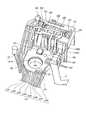
- FIG. 8is a diagram showing the overall configuration of the base unit.
- FIG. 9is a diagram showing the overall configuration of the base unit.
- FIG. 10is a figure which shows the structure of a 2nd terminal holding part.
- FIG. 10is a figure which shows the structure of a 2nd terminal holding part.
- FIG. 11is a diagram showing a configuration of the second terminal holding portion.
- FIG. 12is a diagram showing a circuit board.
- FIG. 13is a circuit diagram for detecting an operation on the first to third switches.
- FIG. 14is a figure explaining the support structure of a 3rd switch.
- FIG. 15is a diagram for explaining the support structure of the third switch.
- FIG. 16is a diagram illustrating a support structure for the third switch.
- FIG. 17is a diagram for explaining the support structure of the third switch.
- FIG. 18is a flowchart which shows the manufacturing method of an energy treatment tool.
- FIG. 19is a figure explaining the manufacturing method of an energy treatment tool.
- FIG. 20is a diagram illustrating a method of manufacturing the energy treatment device.
- FIG. 21is a diagram illustrating a method for manufacturing the energy treatment device.
- FIG. 22is a figure explaining the manufacturing method of an energy treatment tool.
- FIG. 23is a diagram showing a modification of the embodiment.
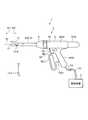
- FIG. 1is a diagram showing a schematic configuration of a treatment system 1 according to this embodiment.
- the treatment system 1treats a target site by applying ultrasonic energy and high-frequency energy to a site (hereinafter referred to as a target site) to be treated in a living tissue.
- the treatment that can be executed by the treatment system 1 according to the present embodimentis a treatment such as coagulation (sealing) of the target site or incision of the target site. Alternatively, the treatment may be such that coagulation and incision are performed simultaneously.
- the treatment system 1is provided with the energy treatment tool 2 and the control apparatus 3, as shown in FIG.
- the X axisis an axis parallel to the central axis Ax (Fig. 1) of the sheath 10.
- the Y axisis an axis orthogonal to the paper surface of FIG.
- the Z axisis an axis along the vertical direction in FIG. Further, hereinafter, one side (+X axis side) along the central axis Ax is described as a tip side Ar1, and the other side ( ⁇ X axis side) is described as a base side Ar2.
- 2 to 6are views for explaining the configuration of the energy treatment device 2.
- the energy treatment device 2is cut along the XZ plane including the central axis Ax, and a part of the cross-sectional view seen from the +Y axis side is directed from the distal end side Ar1 to the proximal end side Ar2. It is illustrated in order. 5 and 6 are views showing the inside of the holding case 6. In addition, in FIG. 5, for convenience of description, the illustration of the ultrasonic transducer 5 is omitted.
- the energy treatment tool 2is, for example, a medical treatment tool that treats a target site while passing through the abdominal wall.
- the energy treatment device 2includes a handpiece 4 and an ultrasonic transducer 5 (FIGS. 1, 3, 4, and 6).
- the handpiece 4includes a holding case 6 (FIGS. 1, 3 to 6), a movable handle 7 (FIGS. 1, 3, 3, 5 and 6), and a first 8A (FIGS. 1, 3, 3, 5 and 6), a second switch 8B (FIGS. 1, 3, 5, and 6), and a pair of third switches 8C (FIGS. 1, FIG. 5), a rotary knob 9 (FIGS. 1, 3, 3, 5 and 6), a sheath 10 (FIGS.
- a jaw 11(FIGS. 1, 2)
- An ultrasonic probe 12(FIGS. 1 to 4 and 6)
- a base unit 13(FIGS. 3 to 6)
- a cable CA(FIGS. 1, 5 and 6) are provided.
- the holding case 6corresponds to the grip according to the present invention.
- the holding case 6supports the entire energy treatment device 2.
- the holding case 6has a substantially cylindrical holding case body 61 that is coaxial with the central axis Ax, and extends from the holding case body 61 to the lower side in FIG. And a fixed handle 62 that is gripped by the operator.
- the holding case 6is divided into two bodies with the XZ plane including the central axis Ax as a boundary.
- the holding case 6is formed by combining the two bodies.
- the first housing 63FIGGS. 3 to 6
- the part on the +Y axis sidewill be referred to as the second housing 64 (FIG. 5). ..
- the movable handle 7receives a closing operation and an opening operation by an operator such as an operator.
- the movable handle 7includes a handle base portion 71, an operating portion 72, and a connecting portion 73.
- the handle base 71is located inside the holding case 6.
- a portion of the handle base 71 on the +Z axis sideis rotatably supported by the holding case 6 about a first rotation axis Rx1 (FIGS. 3 and 6) that is parallel to the Y axis. ..
- a pair of engaging portions 711(FIG.
- the operation portion 72is a portion that receives a closing operation and an opening operation by an operator such as an operator, and is located outside the holding case 6, as shown in FIG.
- the connecting portion 73is a portion that is disposed across the inside and outside of the holding case 6 and connects the handle base 71 and the operating portion 72.
- the movable handle 7receives a closing operation by an operator such as an operator, the movable handle 7 rotates counterclockwise in FIG. 3 about the first rotation axis Rx1. That is, the operation section 72 moves in the direction approaching the fixed handle 62.
- the movable handle 7rotates clockwise in FIG. 3 around the first rotation axis Rx1. That is, the operating portion 72 moves in a direction away from the fixed handle 62.
- connection portion 73when the movable handle 7 is rotated counterclockwise to the maximum in FIG. 3 about the first rotation axis Rx1 by the closing operation, the movable handle 7 is opened by the opening operation.
- a part of the rotary shaft Rx1is always positioned inside the holding case 6 until it is rotated clockwise to the maximum.
- the connecting portion 73is designed in such a shape that the distance between the fixed handle 62 and the movable handle 7 does not become smaller than the outer diameter of the cable CA. This prevents the cable CA from being caught between the fixed handle 62 and the movable handle 7.
- the first and second switches 8A and 8Bare located at the dividing positions of the first and second housings 63 and 64, respectively, and are exposed to the outside from the side surface of the tip side Ar1 of the fixed handle 62. It is provided in each state. Then, the first switch 8A receives a setting operation of the first energy output mode by an operator such as an operator. In addition, the second switch 8B receives a setting operation of the second energy output mode by an operator such as an operator.
- the second energy output modeis an energy output mode different from the first energy output mode.
- an example of the first energy output modeis an energy output mode in which ultrasonic energy and high frequency energy are applied to coagulate and incise a target site.
- An example of the second energy output modeis an energy output mode in which high frequency energy is applied to coagulate the target site.
- the pair of third switches 8Ccorrespond to the first and second levers according to the present invention. As shown in FIG. 5, the pair of third switches 8C are provided so as to face each other along the Y axis and be exposed to the outside from the first and second housings 63 and 64. Then, the pair of third switches 8C are in an output state in at least one of the energy output modes of the first and second energy output modes by the operator such as the operator (the output state of the energy applied to the target site). Accept a change operation to change the.
- the change of the output state in the energy output modeis, for example, switching between a high output mode driven at a relatively high voltage and a low output mode driven at a voltage lower than the high output mode.
- the control device 3may be capable of arbitrarily setting the switching content by the third switch 8C.
- the type of energy(ultrasonic energy or High-frequency energy) is changed (the output state in which both ultrasonic energy and high-frequency energy are applied to the target site or the configuration in which only high-frequency energy is applied to the target site is switched) I don't mind.
- the pair of third switches 8Care pivotally supported by the base unit 13, respectively, and are interlocked in accordance with a changing operation by an operator such as an operator.
- the structure of the third switch 8C and the support structure of the third switch 8C by the base unit 13will be described in "Configuration of base unit" described later.
- the rotary knob 9has a substantially cylindrical shape that is coaxial with the central axis Ax, and is provided on the tip side Ar1 of the holding case body 61 as shown in FIG. Then, the rotation knob 9 receives a rotation operation by an operator such as an operator. By the rotation operation, the rotation knob 9 rotates about the central axis Ax with respect to the holding case body 61. Further, the rotation of the rotary knob 9 causes the jaw 11 and the ultrasonic probe 12 to rotate about the central axis Ax.
- the sheath 10has a substantially cylindrical shape as a whole. As shown in FIG. 1 to FIG. 3, FIG. 5 or FIG. 6, this sheath 10 includes an outer pipe 101 (FIG. 1 to FIG. 3 and FIG. 5), an inner pipe 102 (FIG. 2 and FIG. 3), and a probe. A holder 103 (FIGS. 3 and 6), a slider receiver 104 (FIGS. 3 and 6), and a slider 105 (FIGS. 3, 5 and 6) are provided.
- the outer pipe 101is a cylindrical pipe made of a conductive material such as metal. By the way, the ultrasonic probe 12 vibrates with large ultrasonic energy.
- the ultrasonic probe 12when the vibrating ultrasonic probe 12 comes into contact with the outer pipe 101 made of metal or the like, the ultrasonic probe 12 may be damaged. Further, as will be described later, the ultrasonic probe 12 and the outer pipe 101 form an electrical path through which high-frequency energy flows, and therefore it is necessary to prevent them from contacting each other. Therefore, in this outer pipe 101, at the end portion on the tip side Ar1, as shown in FIG. 2, in order to avoid contact with the ultrasonic probe 12, a pipe expanding portion 101A having a diameter larger than that of other portions is provided. ing. Further, in the outer pipe 101, the outer peripheral surface of the portion other than the expanded tube portion 101A is covered with an electrically insulating outer tube TO (FIGS. 2 and 3).
- the length of the expanded tube portion 101A(the length along the central axis Ax) is set to, for example, about 5 to 15 mm. That is, by making the length of the expanded tube portion 101A as short as possible, the exposed portion of the outer pipe 101 is reduced and the outer pipe 101 is prevented from coming into contact with the ultrasonic probe 12.
- a first pinthat extends in a direction orthogonal to the paper surface of FIGS. 1 and 2 and rotatably supports the jaw 11 around a second rotation axis Rx2 (FIG. 2).
- 101B(FIGS. 1 and 2) is fixed.
- a cutout portion 101Cextending from the tip toward the base end side Ar2 is formed on the +Z axis side.
- the inner pipe 102is a cylindrical pipe having a smaller diameter than the outer pipe 101. Further, the inner pipe 102 is inserted into the outer pipe 101 in a state of being coaxial with the outer pipe 101.
- an arm portion 102A protruding toward the tip side Ar1is provided on the +Z-axis side of the end portion of the tip side Ar1 as shown in FIG.
- a second pin 111which is provided on the jaw 11 and extends in a state parallel to the second rotation axis Rx2 (first pin 101B), is inserted through the arm portion 102A.
- the probe holder 103is made of an electrically insulating material such as resin and has a substantially cylindrical shape. As shown in FIG. 3, the probe holder 103 is inserted into the rotation knob 9 and the holding case body 61 so as to straddle the rotation knob 9 and the holding case body 61. The probe holder 103 holds the ultrasonic probe 12 inserted therein.
- the probe holder 103is mechanically connected to the rotary knob 9 and the outer pipe 101 at the end portion on the tip side Ar1. That is, the probe holder 103, the outer pipe 101, the jaw 11, and the ultrasonic probe 12 rotate together with the rotation knob 9 about the central axis Ax in response to a rotation operation performed on the rotation knob 9 by an operator such as an operator. To do.
- the probe holder 103is provided with an HF active electrode terminal 103A and an electric path 103B.
- the HF active electrode terminal 103Ais made of a conductive material, and has a ring shape extending over the entire circumference in the circumferential direction around the central axis Ax.
- the HF active electrode terminal 103Ais attached to the outer peripheral surface of the probe holder 103 on the base end side Ar2.
- the HF active electrode terminal 103Ais electrically connected to the HF active electrode terminal 151 (FIGS. 3 and 6) provided on the base unit 13.
- the electric path 103Bis made of a conductive material, and extends from the end of the base end side Ar2 to the end of the tip end side Ar1 on the outer peripheral surface of the probe holder 103. As shown in FIG. 3, the electric path 103B has an end portion on the base end side Ar2 electrically connected to the HF active electrode terminal 103A and an end portion on the tip end side Ar1 electrically connected to the outer pipe 101. To do.
- the slider receiver 104is made of an electrically insulating material such as resin and has a substantially cylindrical shape.
- the slider receiver 104is arranged so as to be movable with respect to the probe holder 103 along the central axis Ax with the probe holder 103 inserted therein.
- the end portion of the slider receiver 104 on the tip side Ar1is allowed to move with respect to the probe holder 103 along the central axis Ax, but is restricted from rotating about the central axis Ax, and the inner pipe 102 is prevented. It is fixed to the end portion of the base end side Ar2. That is, the slider receiver 104 and the inner pipe 102 rotate around the central axis Ax together with the rotary knob 9 in response to a rotary operation on the rotary knob 9 by an operator such as an operator.
- the slider 105has a substantially cylindrical shape, and is arranged to be movable along the central axis Ax with respect to the slider receiver 104 with the slider receiver 104 inserted therein. Then, the slider 105 is engaged with the movable handle 7 by the pair of engaging portions 711, as described above.
- the slider 105, the slider receiver 104, and the inner pipe 102operate as described below according to the operation of the movable handle 7 by an operator such as an operator.
- the slider 105is pushed into the distal end side Ar1 along the central axis Ax by the pair of engaging portions 711 according to the closing operation of the movable handle 7 by the operator such as an operator.
- the slider receiver 104receives a pressing force from the slider 105 toward the tip side Ar1 by way of a coil spring 106 (FIGS. 3 and 6) arranged between the slider receiver 104 and the slider 105.
- the inner pipe 102moves in conjunction with the slider receiver 104 along the central axis Ax to the tip side Ar1.
- the arm portion 102Apushes the second pin 111 toward the tip side Ar1.
- the jaw 11rotates counterclockwise in FIG. 2 about the second rotation axis Rx2.
- the second pin 111also moves around the second rotation axis Rx2 while maintaining a constant distance, so that the arm portion 102A deforms toward the +Z axis side provided with the cutout portion 101C.
- the jaw 11rotates clockwise in FIG. 2 about the second rotation axis Rx2. That is, the jaw 11 moves in a direction (opening direction) away from the end of the ultrasonic probe 12 on the tip side Ar1. As described above, the jaw 11 opens and closes with respect to the end portion on the distal end side Ar1 of the ultrasonic probe 12 according to the operation of the movable handle 7 by the operator such as an operator.
- the length of the arm portion 102A(length along the central axis Ax) is set to, for example, about 5 to 10 mm. That is, by making the length of the arm portion 102A as short as possible, contact between the arm portion 102A and the outer pipe 101 is avoided when the arm portion 102A is deformed as the jaw 11 is opened and closed.
- the cross-sectional shape of the direction orthogonal to the central axis Axis formed in a substantially U shape or is formed into a wide shape to secure the strength of the arm portion 102A. When deformed, contact between the arm portion 102A and the outer pipe 101 is avoided.
- the distance between the outer surface of the arm portion 102A and the central axis Axis set to be equal to or less than the distance between the outer peripheral surface of the inner pipe 102 other than the arm portion 102A and the central axis Ax. ..
- the arm portion 102Adoes not slide on the inner surface of the outer pipe 101. That is, the assemblability of the inner pipe 102 with respect to the outer pipe 101 can be improved.
- FIG. 7is a diagram illustrating a positional relationship between the first and second pins 101B and 111.
- FIG. 7is a view of the first and second pins 101B and 111 viewed along a direction orthogonal to the paper surface of FIG.
- the second pin 111 when the jaw 11 is openis shown by a solid line
- the second pin 111 when the jaw 11 is closedis shown by a broken line.
- the YZ plane BP(FIG. 7) passing through the second rotation axis Rx2 is set to pass.
- the second pin 111 with the jaw 11 open and the second pin 111 with the jaw 11 closedare set symmetrically with respect to the plane BP. As a result, the amount of deformation of the arm portion 102A in the Z-axis direction due to the opening and closing of the jaw 11 is minimized, and the amount of force associated with the movement of the inner pipe 102 along the central axis Ax is opened and closed without loss (target area). Can be converted into a gripping force).
- At least a part of the jaw 11is made of a conductive material. Then, the jaw 11 is electrically connected to the HF active electrode terminal 103A by passing through the outer pipe 101 and the electric path 103B.
- the ultrasonic probe 12corresponds to the end effector according to the present invention.
- the ultrasonic probe 12is made of a conductive material and has a long shape that linearly extends along the central axis Ax. Further, as shown in FIG. 2, the ultrasonic probe 12 is inserted into the sheath 10 in a state in which the end portion of the tip side Ar1 projects to the outside. At this time, the end of the ultrasonic probe 12 on the proximal side Ar2 is mechanically connected to the ultrasonic transducer 5 as shown in FIG. 3 or 6. That is, the ultrasonic transducer 5 rotates about the central axis Ax together with the ultrasonic probe 12 in response to a rotating operation of the rotating knob 9 by an operator such as an operator.
- the ultrasonic probe 12transmits the ultrasonic vibration generated by the ultrasonic transducer 5 from the end portion on the base end side Ar2 to the end portion on the tip end side Ar1.
- the ultrasonic vibrationis vertical vibration that vibrates in the direction along the central axis Ax.
- the outer peripheral surface of the ultrasonic probe 12is covered with an electrically insulating inner tube TI (FIG. 2) in order to ensure electrical insulation between the outer pipe 101 or the inner pipe 102 and the ultrasonic probe 12. Has been done.
- the cable CAis detachably connected to the electric cable C0 (FIG. 1) extending from the control device 3. That is, the cable CA is electrically connected to the control device 3 by passing through the electric cable C0.
- the base unit 13has the cable CA attached thereto and is disposed inside the holding case 6.
- the base unit 13electrically connects the cable CA to the HF active electrode terminal 103A provided on the probe holder 103 and the first terminal 52 (FIGS. 4 and 6) provided on the ultrasonic transducer 5. And a function of supporting the pair of third switches 8C.
- the detailed configurations of the cable CA and the base unit 13will be described later in “Configuration of Base Unit”.
- the ultrasonic transducer 5includes a TD (transducer) case 51, a first terminal 52, and an ultrasonic vibrator 53.
- the TD case 51supports the first terminal 52 and the ultrasonic transducer 53, and is detachably connected to the holding case body 61.
- the TD case 51includes a TD case body 511 and a first terminal holding portion 512.
- the TD case main body 511has a bottomed cylindrical shape, and is connected to the holding case main body 61 in a posture in which the opening portion faces the front end side Ar1.
- a straight lineextends along the central axis Ax from the end of the base end side Ar2 toward the tip end side Ar1, and the TD case body
- a cylindrical guide surface 611(FIGS. 4 and 6) having an inner diameter dimension slightly larger than the outer diameter dimension of 511 is provided.
- the first terminal holding portion 512is a tubular body extending along the central axis Ax, and is fitted in the opening portion of the TD case body 511.
- the outer surface of the portion of the first terminal holding portion 512 protruding from the TD case body 511 to the tip side Ar1has four steps 512A to It is formed in a stepped shape having 512D. These four steps 512A to 512D each have a circular cross-section centered on the central axis Ax, and the diameter dimension increases in the order of the four steps 512A to 512D.
- the first terminal 52includes an HF return electrode terminal 521, an IR terminal 522, a US return electrode terminal 523, and a US active electrode terminal 524.
- Each of these terminals 521 to 524is made of a conductive material.
- the HF return electrode terminal 521is provided on the step 512A over the entire circumference of the step 512A in the circumferential direction of the circular cross section.
- the HF return electrode terminal 521is electrically connected to the HF return electrode terminal 152 (FIGS. 3, 4, and 6) provided on the base unit 13 by connecting the ultrasonic transducer 5 to the holding case body 61. Connect to each other.
- the HF return electrode terminal 521is provided over the entire circumference in the circumferential direction of the circular cross-section of the step 512A as described above, it can be rotated by the operator such as an operator to the rotary knob 9. Thus, even when the HF return electrode terminal 152 is rotated about the central axis Ax, the HF return electrode terminal 152 is always electrically connected to the HF return electrode terminal 152.
- the IR terminal 522is provided on the step 512B over the entire circumference in the circumferential direction of the step 512B having a circular cross section.
- the IR terminal 522is electrically connected to the IR terminal 153 (FIGS. 3, 4, and 6) provided on the base unit 13 by connecting the ultrasonic transducer 5 to the holding case body 61. .. Since the IR terminal 522 is provided over the entire circumference in the circumferential direction of the circular cross section of the step 512B as described above, the IR terminal 522 may be rotated by the operator such as an operator to the rotary knob 9. Even when the IR terminal 153 rotates about the central axis Ax, the IR terminal 153 is always electrically connected to the IR terminal 153.
- the ultrasonic transducer 5has, for example, a TD (transducer) memory that stores identification information for identifying the ultrasonic transducer 5.
- the IR terminal 522is electrically connected to the TD memory by passing through an electric path (not shown) provided inside the TD case 51.
- the US return electrode terminal 523is provided on the step 512C over the entire circumference of the step 512C in the circumferential direction of the circular cross section. Then, the US return electrode terminal 523 is electrically connected to the US return electrode terminal 154 (FIGS. 3, 4, and 6) described later by connecting the ultrasonic transducer 5 to the holding case body 61. Since the US return electrode terminal 523 is provided over the entire circumference in the circumferential direction of the circular cross-section of the step 512C as described above, the US return electrode terminal 523 may be rotated by the operator such as an operator to the rotation knob 9. Thus, even when the US return electrode terminal 154 is rotated about the central axis Ax, the US return electrode terminal 154 is always electrically connected to the US return electrode terminal 154.
- the US active electrode terminals 524are provided on the step 512D over the entire circumference in the circumferential direction of the circular cross section of the step 512D.
- the US active electrode terminal 524is electrically connected to the US active electrode terminal 155 (FIGS. 3, 4, and 6) provided on the base unit 13 by connecting the ultrasonic transducer 5 to the holding case body 61. Connect to each other. Since the US active electrode terminals 524 are provided over the entire circumference in the circumferential direction of the circular cross section in the step 512D as described above, the US active electrode terminals 524 can be rotated by the operator such as an operator to the rotation knob 9. Therefore, even when the US active electrode terminal 155 is rotated about the central axis Ax, the US active electrode terminal 155 is always electrically connected to the US active electrode terminal 155.
- the ultrasonic vibrator 53generates ultrasonic vibration under the control of the control device 3.
- the ultrasonic transducer 53is made up of a BLT (Bolting Langevin type transducer).
- the ultrasonic vibrator 53includes a vibrator body 54, a front mass 55, and a back mass 56.
- the vibrator main body 54includes first and second electrode plates 541 and 542, and a plurality of (four in the present embodiment) piezoelectric elements 543.
- the first and second electrode plates 541 and 542are parts to which a drive signal, which is AC power for generating ultrasonic vibration, is supplied from the control device 3.
- the first electrode plate 541includes a plurality (three in the present embodiment) of negative electrode plates 541A and a plurality (two in the present embodiment) of negative electrode wiring portions 541B. And a negative electrode terminal 541C.
- the plurality of negative electrode plates 541Aeach have a disk shape having an opening (not shown) in the center, and are arranged in parallel along the central axis Ax.
- the plurality of negative electrode wiring portions 541Bare portions that electrically connect the outer edge portions of the negative electrode plates 541A adjacent to each other.
- the negative electrode terminal 541Cextends from the outer edge of the negative electrode plate 541A located closest to the base end side Ar2 among the plurality of negative electrode plates 541A toward the base end side Ar2. Then, the negative electrode terminal 541C is electrically connected to the US return electrode terminal 523 by passing through an electric path (not shown) provided inside the TD case 51. That is, the first electrode plate 541 is electrically connected to the US return electrode terminal 523.
- the second electrode plate 542includes a plurality (two in the present embodiment) of positive electrode plates 542A, a positive electrode wiring portion (not shown), and positive electrode terminals (not shown). Equipped with.
- the plurality of positive electrode plates 542Aeach have a disk shape having an opening (not shown) in the center, and are arranged in parallel along the central axis Ax.
- the positive electrode plate 542Ahas substantially the same shape as the negative electrode plate 541A.
- the negative electrode plates 541A and the positive electrode plates 542Aare alternately arranged along the central axis Ax as shown in FIG.
- the negative electrode plate 541A located closest to the base end side Ar2 among the plurality of negative electrode plates 541Ahas a backmass 56 smaller than the positive electrode plate 542A located closest to the base end side Ar2 among the plurality of positive electrode plates 542A. It is arranged at a position close to.
- the positive electrode wiring portion(not shown) is a portion that electrically connects the outer edge portions of the positive electrode plates 542A adjacent to each other.
- the positive electrode terminal(not shown) extends from the outer edge of the positive electrode plate 542A located closest to the base end side Ar2 among the plurality of positive electrode plates 542A toward the base end side Ar2. Then, the positive electrode terminal (not shown) is electrically connected to the US active electrode terminal 524 by passing through an electric path (not shown) provided inside the TD case 51. That is, the second electrode plate 542 is electrically connected to the US active electrode terminal 524.
- the plurality of piezoelectric elements 543each have a disc shape having an opening (not shown) in the center, and are arranged between the negative electrode plate 541A and the positive electrode plate 542A. That is, the plurality of piezoelectric elements 543 are stacked along the central axis Ax. Then, the plurality of piezoelectric elements 543 have a potential difference in the stacking direction along the central axis Ax in accordance with the drive signals supplied to the first and second electrode plates 541 and 542, so that the plurality of piezoelectric elements 543 are arranged along the stacking direction. Expansion and contraction are repeated alternately. As a result, the ultrasonic transducer 53 generates longitudinal ultrasonic vibration having the stacking direction as the vibration direction.
- the front mass 55is made of a conductive material and has a long shape that linearly extends along the central axis Ax. As shown in FIG. 4, the front mass 55 includes an element mounting portion 551, a cross-sectional area changing portion 552, and a probe mounting portion 553.
- the element mounting portion 551is a bolt that extends linearly along the central axis Ax, and has openings (not shown) in the negative electrode plates 541A, openings (not shown) in the positive electrode plates 542A, and And each of the plurality of piezoelectric elements 543 are inserted into each opening (not shown). Then, as shown in FIG. 4, a back mass 56, which is a nut made of a conductive material, is attached to the end of the element mounting portion 551 on the base end side Ar2.
- the cross-sectional area changing portion 552is a portion that is provided at the end portion on the tip side Ar1 of the element mounting portion 551 and that amplifies the amplitude of ultrasonic vibration.
- the end portion of the base end side Ar2is set to have a larger diameter dimension than the element mounting portion 551, and the end portion of the tip end side Ar1 is directed toward the tip end side Ar1. Therefore, it has a truncated cone shape with a reduced cross-sectional area.
- the plurality of negative electrode plates 541A, the plurality of positive electrode plates 542A, and the plurality of piezoelectric elements 543are connected to the cross-sectional area changing portion 552 and the back mass 56 in a state where the element mounting portion 551 penetrates along the central axis Ax. By being sandwiched between them, they are integrally fastened in a substantially cylindrical shape.
- An insulating plate 544(FIG. 4) having electrical insulation properties is interposed between the negative electrode plate 541A located closest to the base end side Ar2.
- the probe mounting portion 553is provided at the end portion on the tip side Ar1 of the cross-sectional area changing portion 552, and extends linearly along the central axis Ax.
- the end of the probe mounting portion 553 on the distal side Ar1is mechanically and electrically connected to the end of the ultrasonic probe 12 on the proximal side Ar2 by connecting the ultrasonic transducer 5 to the holding case body 61. Connect to.
- the back mass 56is electrically connected to the HF return electrode terminal 521 by passing through an electric path (not shown) provided inside the TD case 51. That is, the ultrasonic probe 12 is electrically connected to the HF return electrode terminal 521 by passing through the back mass 56 and the front mass 55.
- the HF return electrode terminal 521is also electrically connected to a TD memory (not shown) built in the ultrasonic transducer 5 by passing through an electric path (not shown) provided inside the TD case 51. ..
- the energy treatment device 2is detachably connected to the control device 3 by an electric cable C0.
- the control device 3comprehensively controls the operation of the energy treatment device 2 by way of the electric cable C0.
- the control device 3passes through the HF return electrode terminal 521, the IR terminal 522, the base unit 13, the cable CA, and the electric cable C0 to thereby electrically connect to the TD memory built in the ultrasonic transducer 5 and electrically.
- the control device 3acquires the identification information for identifying, for example, the ultrasonic transducer 5 stored in the TD memory.
- the control device 3is electrically connected to the handpiece memory 161 (see FIG. 12) provided in the base unit 13 via the base unit 13, the cable CA, and the electric cable C0.
- the control device 3acquires the identification information for identifying, for example, the handpiece 4 stored in the handpiece memory 161.
- control device 3is provided in the base unit 13 by passing through the base unit 13, the cable CA, and the electric cable C0, and detects the setting operation of the first energy output mode to the first switch 8A. It is electrically connected to the first switch element SW1 (FIG. 5). That is, the control device 3 can recognize whether or not the setting operation of the first energy output mode to the first switch 8A has been performed.
- the control device 3is electrically connected to the first electrode plate 541 by way of the US return electrode terminal 523, the base unit 13, the cable CA, and the electric cable C0, and the US active electrode terminal 524 and the base. It is electrically connected to the second electrode plate 542 through the unit 13, the cable CA, and the electric cable C0.
- control device 3is electrically connected to the jaw 11 by passing through the outer pipe 101, the electric path 103B, the HF active electrode terminal 103A, the base unit 13, the cable CA, and the electric cable C0, and the front mass 55. , The back mass 56, the HF return electrode terminal 521, the base unit 13, the cable CA, and the electric cable C0 to electrically connect to the ultrasonic probe 12.
- the control device 3executes the first energy output mode as described below.
- the first energy output modea case of performing output using ultrasonic energy and high frequency energy will be described. That is, the control device 3 supplies a drive signal to the US return electrode terminal 523 (first electrode plate 541) and the US active electrode terminal 524 (second electrode plate 542).
- the plurality of piezoelectric elements 543generate longitudinal vibration (ultrasonic vibration) that vibrates in the direction along the central axis Ax.
- the end portion of the ultrasonic probe 12 on the tip side Ar1vibrates with a desired amplitude due to the longitudinal vibration.
- ultrasonic vibrationis applied to the target portion grasped between the jaw 11 and the end of the ultrasonic probe 12 on the tip side Ar1 from the end. In other words, ultrasonic energy is applied to the target site from the end.
- control device 3applies a high frequency signal that is a high frequency power to the HF active electrode terminal 103A (jaw 11) and the HF return electrode terminal 521 (ultrasonic probe 12) at substantially the same time as the application of the ultrasonic energy to the target site.
- a high-frequency currentflows in the target portion held between the jaw 11 and the end of the ultrasonic probe 12 on the tip side Ar1.
- high frequency energyis applied to the target site.
- frictional heatis generated between the end portion and the target portion due to longitudinal vibration of the end portion on the tip side Ar1 of the ultrasonic probe 12.
- Joule heatis generated in the target site due to the high-frequency current.
- the target siteis solidified (sealed) and incised.
- control device 3is provided in the base unit 13 by passing through the base unit 13, the cable CA, and the electric cable C0, and detects the setting operation of the second energy output mode to the second switch 8B. It is electrically connected to the second switch element SW2 (FIG. 5). That is, the control device 3 can recognize whether or not the setting operation of the second energy output mode to the second switch 8B has been performed. Then, when the setting operation of the second energy output mode to the second switch 8B is performed, the control device 3 executes the second energy output mode as described below.
- the second energy output modea case of performing output using high frequency energy will be described.
- the control device 3supplies a high frequency signal which is a high frequency power to the HF active electrode terminal 103A (jaw 11) and the HF return electrode terminal 521 (ultrasonic probe 12).
- a high-frequency currentflows in the target portion held between the jaw 11 and the end of the ultrasonic probe 12 on the tip side Ar1.
- a high-frequency currentflows in the target portion, so that Joule heat is generated. Thereby, the target site is sealed.
- control device 3is provided in the base unit 13 by passing through the base unit 13, the cable CA, and the electric cable C0, and a third switch element SW3 (which detects a change operation to the third switch 8C). (See FIGS. 13, 16 and 17). That is, the control device 3 can recognize whether or not the change operation to the third switch 8C has been performed. Then, when the change operation to the third switch 8C is performed, the control device 3 changes the power of the drive signal or the high frequency signal so that at least one of the first and second energy output modes. Switching the output state in the energy output mode.
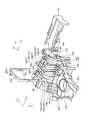
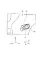
- FIG. 8 and 9are views showing the overall configuration of the base unit 13. Specifically, FIG. 8 is a view of the base unit 13 viewed from the +Y axis side. FIG. 9 is a view of the base unit 13 viewed from the ⁇ Y axis side. Note that, in FIG. 8, for convenience of description, the switch support portion 18 and the metal contact 19 are not shown. Further, in FIG. 9, the resin RE is represented by dots for convenience of description. The same applies to FIG. As shown in FIG. 8 or 9, the base unit 13 includes a base member 14, a second terminal 15, a circuit board 16 (see FIG. 12), a flexible board 17, and a switch support portion 18 (FIG. 5). And a metal contact 19 (see FIG. 16) attached to the switch support portion 18. The circuit board 16 and the flexible board 17 correspond to the boards according to the present invention. Further, the metal contact 19 corresponds to the contact according to the present invention.
- the base member 14is made of an electrically insulating material and is fixed inside the holding case 6 by a plurality of fixing portions 14A (FIGS. 8 and 9) such as boss holes.
- the base member 14includes a base member main body 141, a second terminal holding portion 142, and a terminal pressing member 143 (FIG. 9).
- the base member main body 141is formed in a flat plate shape, and is arranged inside the holding case 6 in a posture in which each plate surface is parallel to the XZ plane. Further, the base member main body 141 extends inside the holding case 6 from the ⁇ Z axis side end of the fixed handle 62 to the holding case main body 61.
- a portion on one end side of the cable CAis attached to the end portion on the ⁇ Z axis side of the base member main body 141 by a binding band CT. Then, the other end portion of the cable CA is drawn out of the fixed handle 62 from the side surface of the fixed handle 62 on the ⁇ Z axis side.
- a part of the plurality of fixing portions 14Athat is, the fixing portion 14A1 is provided at a position close to the attachment position of the one end side portion of the cable CA. This reduces the load applied to the base unit 13 when the other end of the cable CA is pulled.
- the cable CAmay be detachable from the base unit 13 with a connector.
- the switch support portion 18is provided at the +Z-axis side portion around the third rotation axis Rx3 which penetrates the front and back and is parallel to the Y axis, as shown in FIG. 8 or 9.
- a circular bearing hole 141A that rotatably supportsis formed.
- FIG. 10 and 11are diagrams showing the configuration of the second terminal holding portion 142.
- FIG. 10is a perspective view of the second terminal holding portion 142 viewed from the +Y axis side.
- FIG. 11is an exploded perspective view of the second terminal holding portion 142 and the terminal pressing member 143 as seen from the ⁇ Y axis side.
- the second terminal holding portion 142is a tubular body extending along the X axis (center axis Ax), and is integrated with the end portion of the base member main body 141 on the +Z axis side. Has been formed.
- the ultrasonic transducer 5is connected to the holding case body 61, as shown in FIG. 3, FIG. 4, or FIG. 6, the first terminal holding portion 512 of the ultrasonic transducer 5 is changed to the second terminal.
- the holder 142is inserted inside.
- the outer surface of the second terminal holding portion 142is formed in a stepped shape having four steps 142A to 142D in order from the tip side Ar1.
- Each of these four steps 142A to 142Dhas a circular sectional shape centered on the central axis Ax, and the diameter dimension increases in the order of the four steps 142A to 142D.
- the inner diameters of the four steps 142A to 142Dare set to be slightly larger than the outer diameters of the four steps 512A to 512D in the ultrasonic transducer 5.
- a pair of openings 142E to 142I penetrating along the Z axisare formed in the four steps 142A to 142D, respectively.
- a notched portion 142Jis formed that is notched up to.
- the terminal holding member 143is attached to the outer surface of the second terminal holding portion 142 on the ⁇ Y axis side and holds the second terminals 15 attached to the four steps 142A to 142D. Is.
- a snap fitis adopted as the structure for fixing the terminal pressing member 143 to the second terminal holding portion 142.
- the second terminal 15includes an HF active electrode terminal 151, an HF return electrode terminal 152, an IR terminal 153, a US return electrode terminal 154, and a US active electrode terminal 155.
- Prepare Each of these terminals 151 to 155is made of a conductive material.
- the US active electrode terminal 155includes a terminal base portion 155A and a pair of leaf spring portions 155B, and has a generally U-shape.
- the terminal base 155Ahas a flat plate shape extending along the Z axis, and is a portion fixed to the outer surface on the ⁇ Y axis side of the step 142D in a posture in which each plate surface is orthogonal to the Y axis.
- the pair of leaf spring portions 155Bare portions extending from both ends of the terminal base portion 155A toward the +Y-axis side, respectively, and are elastically deformable in the Z-axis direction with the both ends as fulcrums. Further, when the terminal base portion 155A is fixed to the step 142D, each part of the pair of leaf spring portions 155B is exposed inside the second terminal holding portion 142 through the pair of opening portions 142I.
- the US active electrode terminal 155comes into contact with the US active electrode terminal 524 of the ultrasonic transducer 5 when the ultrasonic transducer 5 is connected to the holding case body 61. It is electrically connected to the active electrode terminal 524.
- the cable CAincludes the US active electrode cable CA1, the US return electrode cable CA2, the HF return electrode cable CA3, the HF active electrode cable CA4, the memory cable CA5, and the first to third switch cables CA6 to CA8. It is composed of eight cables (see FIG. 21).
- the electric cable C0is also composed of eight cables.
- the US active electrode cable CA1 and the US return electrode cable CA2serve as an electric path for the drive signal supplied from the control device 3 via the electric cable C0. Then, the US active electrode cable CA1 is directly and electrically connected to the US active electrode terminal 155 (see FIG. 21).
- the HF return electrode cable CA3 and the HF active electrode cable CA4serve as an electric path of the high frequency signal supplied from the control device 3 via the electric cable C0.
- the memory cable CA5is used for communication between the control device 3 and the TD memory (not shown) built in the ultrasonic transducer 5 and the handpiece memory 161 (see FIG. 12) mounted on the circuit board 16. It is an electric path that is used.
- the first to third switch cables CA6 to CA8are cables that electrically connect the electric cable C0 and the first to third switch elements SW1 to SW3, respectively.
- the US return electrode terminal 154includes a terminal base portion 154A and a pair of leaf spring portions 154B, and has a substantially U-shape as a whole.
- the terminal base 154Ahas a flat plate shape whose length in the longitudinal direction is shorter than that of the terminal base 155A in accordance with the outer diameter dimension of the step 142C. Then, the terminal base portion 154A is fixed to the outer surface of the step 142C on the ⁇ Y axis side in a posture in which each plate surface is orthogonal to the Y axis.
- the pair of leaf spring portions 154Bare portions extending from both ends of the terminal base portion 154A toward the +Y-axis side, and are elastically deformable in the Z-axis direction with the both ends as fulcrums.
- the pair of leaf spring portions 154Beach have the same shape as the leaf spring portion 155B.
- each part of the pair of leaf spring portions 154Bis exposed inside the second terminal holding portion 142 through the pair of openings 142H.
- the US return electrode terminal 154comes into contact with the US return electrode terminal 523 of the ultrasonic transducer 5 when the ultrasonic transducer 5 is connected to the holding case body 61. It is electrically connected to the return electrode terminal 523.
- the US return electrode cable CA2is directly and electrically connected to the US return electrode terminal 154 (see FIG. 21).
- the IR terminal 153includes a terminal base portion 153A and a pair of leaf spring portions 153B, and an IR terminal main body 153C (FIG. 11) having a substantially U-shape as a whole and an IR terminal main body 153C.
- the terminal base portion 153Ais integrally formed with the protrusion portion 153D (FIG. 11) protruding toward the ⁇ Z axis side.
- the terminal base 153Ahas a flat plate shape whose length in the longitudinal direction is shorter than that of the terminal base 154A in accordance with the outer diameter of the step 142B. Then, the terminal base portion 153A is fixed to the outer surface of the step 142B on the ⁇ Y axis side in a posture in which each plate surface is orthogonal to the Y axis.
- the pair of leaf spring portions 153Bare portions extending from both ends of the terminal base portion 153A toward the +Y axis side, and are elastically deformable in the Z axis direction with the both ends as fulcrums.
- the pair of leaf spring portions 153Bhave the same shape as the leaf spring portion 155B. Further, when the terminal base portion 153A is fixed to the step 142B, each part of the pair of leaf spring portions 153B is exposed inside the second terminal holding portion 142 through the pair of opening portions 142G.
- the IR terminal 153comes into contact with the IR terminal 522 of the ultrasonic transducer 5 so as to electrically connect with the IR terminal 522. Connect to each other.
- the HF return electrode terminal 152includes a terminal base portion 152A and a pair of leaf spring portions 152B, and has a generally U-shaped HF return electrode terminal body 152C (FIG. 11) and The return electrode terminal main body 152C is integrally formed with a protrusion 152D (FIG. 11) protruding from the terminal base 152A toward the ⁇ Z axis side.
- the terminal base portion 152Ahas a flat plate shape whose length in the longitudinal direction is shorter than that of the terminal base portion 153A in accordance with the outer diameter dimension of the step 142A. Then, the terminal base portion 152A is fixed to a portion on the base end side Ar2 on the ⁇ Y axis side outer surface of the step 142A with each plate surface orthogonal to the Y axis.
- the pair of leaf spring portions 152Bare portions extending from both ends of the terminal base portion 152A toward the +Y-axis side, and are elastically deformable in the Z-axis direction with the both ends as fulcrums.
- the pair of leaf spring portions 152Beach have the same shape as the leaf spring portion 155B. Further, when the terminal base portion 152A is fixed to the step 142A, a part of each of the pair of leaf spring portions 152B is exposed inside the second terminal holding portion 142 through the pair of opening portions 142F.
- the HF return electrode terminal 152comes into contact with the HF return electrode terminal 521 of the ultrasonic transducer 5 when the ultrasonic transducer 5 is connected to the holding case body 61, and thereby the HF return electrode terminal 521. It is electrically connected to the return electrode terminal 521.
- the HF active electrode terminal 151includes a terminal base portion 151A and a pair of leaf spring portions 151B, and has a generally U-shape.
- the terminal base 151Ahas the same shape as the terminal base 152A.
- the terminal base 151Ais fixed to the tip side Ar1 on the outer surface of the step 142A on the ⁇ Y axis side in a posture in which each plate surface is orthogonal to the Y axis.
- the pair of leaf spring portions 151Bare portions extending from both ends of the terminal base portion 151A toward the +Y-axis side, and are elastically deformable in the Z-axis direction with the both ends as fulcrums.
- the pair of leaf spring portions 151Beach have the same shape as the leaf spring portion 155B. Further, in the state where the terminal base portion 151A is fixed to the step 142A, each part of the pair of leaf spring portions 151B is exposed inside the second terminal holding portion 142 through the pair of opening portions 142E.
- the HF active electrode terminal 151(a pair of leaf spring portions 151B) is brought into contact with the HF active electrode terminal 103A provided on the probe holder 103 to electrically connect to the HF active electrode terminal 103A. Then, the HF active electrode cable CA4 is directly and electrically connected to the HF active electrode terminal 151 (see FIG. 21).
- the leaf spring portions 151B, 152B, 153B, 154B, 155B of the terminals 151 to 155all have the same shape. Therefore, it is possible to set the contact pressures of the terminals 151 to 155 to the terminals 103A and 521 to 524 to be the same.
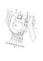
- FIG. 12is a diagram showing the circuit board 16. Specifically, FIG. 12 is a view of the arrangement position of the circuit board 16 in the base unit 13 as viewed from the ⁇ Y axis side. As shown in FIG. 12, the circuit board 16 is arranged at a position facing the bearing hole 141A on the ⁇ Y-axis side plate surface of the base member main body 141. The circuit board 16 is formed with a through hole 16A penetrating through the front and back and communicating with the bearing hole 141A. Further, the circuit board 16 includes a plurality of electric wirings including the first to third electric wirings SL1 to SL3 (see FIG. 13), the handpiece memory 161 (FIG. 12), and the first to third diodes. 162 to 164 (see FIG. 20) are mounted.
- the first electric wiring SL1is electrically connected to the first to third switch elements SW1 to SW3 by way of the first electric wiring SL1′ mounted on the flexible substrate 17 (see FIG. 13). ..
- the second electric wiring SL2is electrically connected to the first and second diodes 162 and 163, respectively, and is passed through the second electric wiring SL2′ mounted on the flexible substrate 17 to thereby provide the first and second electric wirings.
- the two switch elements SW1 and SW2are electrically connected to each other (see FIG. 13).
- the third electric wiring SL3is electrically connected to the third diode 164 and electrically connected to the third switch SW3 by way of the third electric wiring SL3′ mounted on the flexible substrate 17. (See FIG. 13).
- the first to third switch cables CA6 to CA8are connected to the circuit board 16, respectively.
- the first to third electric wirings SL1 to SL3are electrically connected to the first to third switch cables CA6 to CA8, respectively.
- the handpiece memory 161stores identification information for identifying the handpiece 4, for example.
- the circuit board 16is connected with the projecting portion 153D of the IR terminal 153, the projecting portion 152D of the HF return electrode terminal 152, the memory cable CA5, and the HF return electrode cable CA3, respectively.
- the handpiece memory 161is connected to the memory cable CA5 that functions as a signal line used for communication with the control device 3 by passing through a pair of electric wirings (not shown) mounted on the circuit board 16.
- the HF return electrode cable CA3that functions as a ground line used for communication with the control device 3, respectively.
- the handpiece memory 161is electrically connected to the IR terminal 153 and the HF return electrode terminal 152, respectively, via the pair of electric wires. That is, the TD memory (not shown) built in the ultrasonic transducer 5 is electrically connected to the memory cable CA5 and the HF return electrode cable CA3, like the handpiece memory 161.
- the flexible board 17is connected to the circuit board 16, and the positions where the first and second switches 8A and 8B are arranged from the position where the flexible board 17 is connected to the circuit board 16 and the metal contacts 19 attached to the switch support 18 (see FIG. 16, see FIG. 17).
- first to third electric wirings SL1' to SL3' and first and second switch elements SW1 and SW2are mounted on the flexible substrate 17.
- the first electric wiring SL1′is a wiring that relays the first electric wiring SL1 and the first to third switch elements SW1 to SW3 (see FIG. 13).
- the second electric wiring SL2′is a wiring that relays the second electric wiring SL2 and the first and second switch elements SW1 and SW2 (see FIG. 13).
- the third electric wiring SL3′is a wiring that relays the third electric wiring SL3 and the third switch element SW3 (see FIG. 13).
- the first and third electric wirings SL1' and SL3'correspond to the wiring pattern according to the present invention.
- the first switch element SW1is provided at a position facing the first switch 8A (FIG. 5), and detects a setting operation of the first energy output mode for the first switch 8A.
- the second switch element SW2is provided at a position facing the second switch 8B (FIG. 5) and detects a setting operation of the second energy output mode for the second switch 8B.
- FIG. 13is a circuit diagram for detecting an operation on the first to third switches 8A to 8C. Then, the control device 3 recognizes that the first to third switches 8A to 8C have been operated, as described below.
- the first switch element SW1brings the first and second electric wirings SL1′ and SL2′ into conduction. Then, by the first to third diodes 162 to 164, the second switch cable CA7 (second electric wirings SL2 and SL2') to the first switch cable CA6 (first electric wirings SL1 and SL1'). Current flows only to).
- the control device 3recognizes that the setting operation of the first energy output mode for the first switch 8A has been performed.
- the second switch SW2causes the first and second electric wirings SL1' and SL2' to be conductive. Then, by the first to third diodes 162 to 164, the first switch cable CA6 (first electric wirings SL1 and SL1') to the second switch cable CA7 (second electric wirings SL2 and SL2'). Current flows only to). By recognizing the current flow, the control device 3 recognizes that the setting operation of the second energy output mode to the second switch 8B has been performed.
- the third switch SW3brings the first and third electric wirings SL1' and SL3' into a conductive state or a non-conductive state. Then, in the conductive state, the first to third diodes 162 to 164 allow the third switch cable CA8 (third electrical wiring SL3, SL3′) to the first switch cable CA6 (first switch). The current flows only toward the electric wirings SL1 and SL1'). By recognizing the current flow, the control device 3 recognizes whether or not the change operation to the third switch 8C has been performed.
- the control device 3switches to one of the high output mode and the low output mode in a state (contact state) where the first and third electric wirings SL1′ and SL3′ are in conduction. Further, the control device 3 switches to the other of the high output mode and the low output mode when the first and third electric wirings SL1′ and SL3′ are in the non-conducting state (non-contact state). That is, the output state of the energy applied to the target part is set to be different in the contact state and the non-contact state.
- FIG. 14 to 17are views for explaining the support structure of the third switch 8C.
- FIG. 14is a diagram of the holding case 6 viewed from the +Y axis side.
- FIG. 15is a view of the holding case 6 viewed from the ⁇ Y axis side.
- 16 and 17are views of the switch support 18 viewed from the +Y axis side.
- the pair of third switches 8Chave the same shape.
- the third switch 8Cincludes a knob 81 and a shaft 82 as shown in FIG. 5 or FIGS. 14 to 17.
- the knob 81is a part that receives a change operation by an operator such as an operator.
- the knob 81has a tapered shape that becomes thinner toward the tip side Ar1.
- the shaft portion 82projects along the Y-axis from the base end side Ar2 portion of the knob portion 81.
- the shaft portion 82has a rectangular cross section.
- the switch support portion 18corresponds to the driving body according to the present invention.
- the switch support portion 18is made of an electrically insulating material, and faces the bearing hole 141A on the +Y-axis side plate surface of the base member main body 141, as shown in FIG. 5, FIG. 16, or FIG. It is arranged at the position.
- the switch support portion 18includes a support portion main body 181 and a spring portion 182.
- the support portion main body 181includes a columnar shaft 181A that extends along the Y axis and is inserted into the bearing hole 141A.
- the outer diameter of the columnar shaft 181Ais set to be slightly larger than the inner diameter of the bearing hole 141A.
- the columnar shaft 181Ais rotatably supported by the bearing hole 141A, and the switch support portion 18 is rotatable about the third rotation axis Rx3.
- the columnar shaft 181Ahas a rectangular cross-section fitting hole 181B (wherein the shaft portions 82 of the pair of third switches 8C, which penetrate the Y-axis and project into the holding case 6, are fitted respectively. (FIGS. 5, 16 and 17) are formed. That is, the pair of third switches 8C are pivotally supported by the bearing hole 141A and the columnar shaft 181A at the center position in the Y-axis direction inside the holding case 6 about the third rotation axis Rx3.
- the spring portion 182is a portion that protrudes from the ⁇ Z axis side end portion of the support portion main body 181 to the base end side Ar2 and is bent and extended to the +Z axis side.
- the support portion main body 181is configured to be elastically deformable in the X axis direction with the end portion on the ⁇ Z axis side as a fulcrum.
- a protrusion 182Athat protrudes toward the base end side Ar2 is provided at the end portion on the +Z axis side.
- the base member body 141as shown in FIG. 16 or FIG.
- the +Y-axis side plate surfaceis engaged with the switch support portion 18 so as to project from the base end side Ar2 position to the +Y-axis side.
- the protrusion 144is formed.
- first and second engagement recesses 144A and 144B corresponding to the shape of the protrusion 182A of the spring portion 182are juxtaposed in the Z-axis direction on the side surface of the tip side Ar1. ..
- the metal contact 19is attached to the end of the switch support 18 on the +Z axis side as shown in FIG. 16 or 17.
- the metal contact 19constitutes the third switch element SW3. That is, the metal contacts 19 are brought into contact with (contacted with) a part (FIG. 10) of the first and third electric wirings SL1′, SL3′ exposed to the outside of the flexible substrate 17, respectively. , 3rd electric wiring SL1', SL3' are made conductive. Further, the metal contact 19 is separated (in a non-contact state) from a part of the first and third electric wirings SL1′, SL3′, so that the first and third electric wirings SL1′, SL3′. Is turned off.
- the switch support portion 18is 16 rotates counterclockwise in FIG. 16 about the rotation axis Rx3 of 3 to be in the state shown in FIG. 16 (first state).
- the metal contact 19is separated from a part of the first and third electric wirings SL1′ and SL3′ exposed to the outside of the flexible substrate 17. That is, the first and third electric wirings SL1' and SL3' are in a non-conducting state.
- the switch support portion 18is 17 is rotated clockwise about the rotation axis Rx3 of 3 to be in the state (second state) shown in FIG.
- the metal contacts 19come into contact with part of the first and third electric wirings SL1′ and Sl3′ exposed to the outside of the flexible substrate 17, respectively. That is, the first and third electric wirings SL1' and SL3' are electrically connected.
- the tip side Ar1 portion of the third switch 8Cis tilted to the ⁇ Z axis side and the tip side Ar1 portion of the third switch 8C is tilted to the +Z axis side
- the portion 182slides on the side surface of the engagement protrusion 144 on the tip side Ar1 while elastically deforming in the X-axis direction.
- the protrusion 182Ais the first engagement concave portion located on the +Z axis side. 144A (FIG. 16). Thereby, the first state is maintained.
- the protrusion 182Ais the second engagement recess located on the ⁇ Z axis side when the tip side Ar1 of the third switch 8C is tilted to the +Z axis side (in the second state). 144B (FIG. 17).
- the spring portion 182applies vibration to the pair of third switches 8C in response to the engagement of the protrusion 182A with the first and second engagement recesses 144A and 144B.
- the pair of third switches 8Cmove in an interlocking manner, they can be operated by either a right-handed person or a left-handed person, and it is possible to easily confirm which mode the mode is by visually recognizing the position of the tip side Ar1. You can
- FIG. 18is a flowchart showing a method for manufacturing the energy treatment device 2.
- 19 to 22are diagrams illustrating a method of manufacturing the energy treatment device 2.
- the steps S1 and S2 described beloware performed in different places. Specifically, the step S2 is performed in a place such as a clean room having a relatively high cleanliness (cleanliness) (hereinafter, referred to as a second place).
- the step S1is performed in a place (hereinafter, referred to as a first place) such as a clean room having a lower degree of cleanliness (cleanness) than the second place.
- steps S1 and S2will be described in this order.
- step S1the worker assembles the base unit 13 in the first place as described below.
- the operatorattaches the second terminal 15 to the base member 14 as shown in FIG. 11 (step S1A).
- step S1Aas shown in FIGS. 19 and 20, the worker connects the flexible board 17 and the cables CA3, CA5 to CA8 to the circuit board 16 with solder SO (step S1B).
- step S1Cthe operator sets the circuit board 16 on the base member 14 as described below (step S1C). Specifically, the operator fixes the cable CA to the base member 14 with the binding band CT. Further, as shown in FIG. 21, the worker connects the cables CA4, CA2, CA1 to the terminals 151, 154, 155 with solder SO, respectively. Further, the worker connects the projecting portions 152D and 153D of the terminals 152 and 153 to the circuit board 16 with the solder SO, respectively.
- step S1Cthe worker covers the plate surface of the base member main body 141 on the side on which the circuit board 16 is installed with a resin RE such as an epoxy resin (step S1D).
- a resin REsuch as an epoxy resin
- step S2the operator assembles the energy treatment device 2 in the second place as described below.
- the workerassembles the base unit 13 assembled in step S1 from the +Y axis side to the first housing 63 (step S2A).
- step S2Athe worker assembles the unit in which the rotary knob 9, the sheath 10, the jaw 11, and the ultrasonic probe 12 are integrated with the first housing 63 from the +Y axis side (step S2B).
- the end of the ultrasonic probe 12 on the base end side Ar2passes through the notch 142J formed in the second terminal holding part 142 and is disposed inside the second terminal holding part 142.
- step S2Bthe worker assembles the second housing 64 with the first housing 63 (step S2C). Further, a pair of third switches 8C is attached to the first and second housings 63 and 64, respectively.
- steps S2A to S2Cwith respect to the first housing 63, the base unit 13, the unit in which the rotation knob 9, the sheath 10, the jaw 11, and the ultrasonic probe 12 are integrated, and the second unit
- the housing 64is assembled in the same direction (from the +Y axis side).
- the energy treatment device 2is manufactured through the above steps S1 and S2.
- the pair of third switches 8Chas a first state (states shown by solid lines in FIGS. 14 and 15) in response to a change operation by an operator such as an operator. ) Or the second state (the state shown by the alternate long and short dash line in FIGS. 14 and 15). Further, the pair of third switches 8C are interlocked by the above-mentioned switch support portion 18 in accordance with the change operation. Therefore, an operator such as a surgeon confirms whether any one of the pair of third switches 8C is in the first state or the second state, so that the energy output state is It is possible to determine which output state is currently (high output mode or low output mode). Therefore, according to the energy treatment device 2 according to the present embodiment, it is possible for an operator such as an operator to easily determine the current output state of energy, and it is possible to improve convenience. Produce an effect.
- the third switch element SW3includes a part of the first electric wiring SL1′ exposed to the outside of the flexible substrate 17 and one of the third electric wiring SL3′. And a metal contact 19 attached to the switch support 18. Therefore, the third switch element SW3 can be configured with a simple structure.
- the pair of third switches 8Cincludes the bearing hole 141A and the columnar shaft 181A, and the third rotation shaft is located at the center position in the Y axis direction inside the holding case 6. It is rotatably supported around Rx3. Therefore, in the case where a pair of third switches 8C configured to interlock with each other is adopted, any of the third switches 8C of the pair of third switches 8C is changed. Also, the rattling of the pair of third switches 8C can be suppressed, and the changing operation can be smoothly performed.
- the pair of third switches 8Cface each other along the Y-axis and are provided outside the holding case 6 from the first and second housings 63 and 64, respectively. It is provided in an exposed state. Therefore, an operator such as a surgeon can perform the changing operation regardless of whether the fixed handle 62 is held by the right hand or the left hand. Therefore, the convenience can be further improved.
- the switch support portion 18includes the spring portion 182 having the protrusion 182A.
- the base member 14maintains the first state by engaging with the protrusion 182A in the first state (state shown in FIG. 16), and the second state.
- the second engagement recess 144Bthat maintains the second state by engaging the protrusion 182A in the state (shown in FIG. 17).
- the spring portion 182vibrates the pair of third switches 8C in response to the engagement of the protrusion 182A with the first and second engagement recesses 144A and 144B. That is, a click feeling is given to the operator who operates the pair of third switches 8C. Therefore, an operator such as an operator can recognize that the pair of third switches 8C has been set to the first state or the second state. Therefore, the convenience can be further improved.
- FIG. 23is a diagram showing a modified example of the present embodiment.
- the base member 140 shown in FIG. 23may be adopted instead of the base member 14.
- the base member 140 according to this modified exampleis configured by an MID (Molded Interconnect Device). That is, as shown in FIG. 23, the base member 140 is made of a resin molded product having the wiring WI formed on the outer surface thereof.
- the energy treatment tool according to the present inventionis configured to apply both ultrasonic energy and high frequency energy to the target site, but is not limited to this, and ultrasonic energy, high frequency energy, and A configuration in which at least one of thermal energy is applied may be adopted.
- applying heat energy to the target sitemeans transmitting the heat generated in the heater or the like to the target site.
- the base member according to the present inventionincludes the base member main body 141, the second terminal holding portion 142 and the terminal pressing member 143.
- the terminal holding portion 142 and the terminal pressing member 143may be omitted and the base member main body 141 alone may be used.
- the pair of third switches 8C and the switch support portion 18are configured to be rotatable about the third rotation axis Rx3 in response to a changing operation by an operator such as an operator.
- the first and second levers and the driving body according to the present inventionmay be configured to be slidable according to the changing operation.
Landscapes
- Health & Medical Sciences (AREA)
- Surgery (AREA)
- Engineering & Computer Science (AREA)
- Life Sciences & Earth Sciences (AREA)
- Biomedical Technology (AREA)
- Public Health (AREA)
- Nuclear Medicine, Radiotherapy & Molecular Imaging (AREA)
- Veterinary Medicine (AREA)
- General Health & Medical Sciences (AREA)
- Heart & Thoracic Surgery (AREA)
- Medical Informatics (AREA)
- Molecular Biology (AREA)
- Animal Behavior & Ethology (AREA)
- Physics & Mathematics (AREA)
- Otolaryngology (AREA)
- Plasma & Fusion (AREA)
- Dentistry (AREA)
- Mechanical Engineering (AREA)
- Surgical Instruments (AREA)
Abstract
Description
Translated fromJapanese本発明は、エネルギ処置具に関する。The present invention relates to an energy treatment tool.
従来、生体組織における処置の対象となる部位(以下、対象部位と記載)に対してエネルギを付与することによって当該対象部位を処置するエネルギ処置具が知られている(例えば、特許文献1参照)。
特許文献1に記載のエネルギ処置具は、エネルギを付与することによって対象部位を処置するエンドエフェクタと、当該エンドエフェクタを支持するとともに、操作者によって把持されるグリップとを備える。また、当該グリップの両側面には、術者等の操作者による変更操作をそれぞれ受け付ける一対のプッシュボタンが設けられている。なお、当該変更操作は、対象部位に対して付与するエネルギの出力状態を変更する操作である。すなわち、一対のプッシュボタンのいずれかが押下されると、対象部位に対して付与するエネルギの出力状態が変更される。BACKGROUND ART Conventionally, there is known an energy treatment tool that treats a target portion of a biological tissue by applying energy to the target portion (hereinafter referred to as a target portion) (for example, refer to Patent Document 1). ..
The energy treatment device described in
しかしながら、特許文献1に記載のエネルギ処置具では、一対のプッシュボタンは、カンチレバー要素によって、変更操作を受け付けた後(押下された後)、元の状態に戻る。このため、術者等の操作者は、プッシュボタンの状態を見ても、変更操作を行った状態であるか、変更操作を行っていない状態であるかを判別することができない。すなわち、術者等の操作者は、プッシュボタンの状態を見ても、対象部位に対して付与するエネルギの出力状態が現在、どの出力状態であるかを判別することができない。
そこで、術者等の操作者に対して現在のエネルギの出力状態を容易に判別させることができ、利便性を向上させることができる技術が要望されている。However, in the energy treatment device described in
Therefore, there is a demand for a technique that allows an operator such as an operator to easily determine the current output state of energy and improve convenience.
本発明は、上記に鑑みてなされたものであって、利便性を向上させることができるエネルギ処置具を提供することを目的とする。The present invention has been made in view of the above, and an object thereof is to provide an energy treatment device that can improve convenience.
上述した課題を解決し、目的を達成するために、本発明に係るエネルギ処置具は、エネルギを付与することによって生体組織を処置するエンドエフェクタと、前記エンドエフェクタを支持するとともに操作者によって把持されるグリップと、前記グリップの外部に露出した状態で設けられ、操作者による前記エネルギの出力状態を変更する変更操作に応じて移動する第1のレバーと、前記グリップの外部に露出した状態で設けられ、前記変更操作に応じて移動する第2のレバーと、前記グリップの内部に配置されたベース部材と、前記ベース部材に対して前記第1のレバーと前記第2のレバーとともに移動可能に取り付けられ、前記第1のレバーまたは前記第2のレバーへの前記変更操作に応じて前記第1のレバーと前記第2のレバーとを連動させる駆動体と、を備える。In order to solve the above-mentioned problems and achieve an object, an energy treatment device according to the present invention is an end effector that treats a biological tissue by applying energy, and an end effector that supports the end effector and is gripped by an operator. And a first lever that is exposed to the outside of the grip and that moves in response to a changing operation that changes the output state of the energy by the operator, and an exposed state that is exposed to the outside of the grip. A second lever that moves in response to the change operation, a base member that is disposed inside the grip, and a movably attached to the base member together with the first lever and the second lever. And a driving body that interlocks the first lever and the second lever in response to the change operation to the first lever or the second lever.
本発明に係るエネルギ処置具によれば、利便性を向上させることができる、という効果を奏する。The energy treatment device according to the present invention has the effect of improving convenience.
以下に、図面を参照しつつ、本発明を実施するための形態(以下、実施の形態)について説明する。なお、以下に説明する実施の形態によって本発明が限定されるものではない。さらに、図面の記載において、同一の部分には同一の符号を付している。A mode for carrying out the present invention (hereinafter, an embodiment) will be described below with reference to the drawings. The present invention is not limited to the embodiments described below. Further, in the description of the drawings, the same reference numerals are given to the same parts.
〔処置システムの概略構成〕
図1は、本実施の形態に係る処置システム1の概略構成を示す図である。
処置システム1は、生体組織における処置の対象となる部位(以下、対象部位と記載)に対して超音波エネルギと高周波エネルギとを付与することによって、当該対象部位を処置する。なお、本実施の形態に係る処置システム1によって実行可能とする処置は、対象部位の凝固(封止)、あるいは対象部位の切開等といった処置である。また、凝固と切開とを同時に行うような処置であってもよい。そして、処置システム1は、図1に示すように、エネルギ処置具2と、制御装置3とを備える。[Schematic configuration of treatment system]
FIG. 1 is a diagram showing a schematic configuration of a
The
〔エネルギ処置具の構成〕
なお、以下では、エネルギ処置具2の構成を説明するにあたって、互いに直交するX軸、Y軸、及びZ軸のXYZ座標軸を用いる。X軸は、シース10の中心軸Ax(図1)に平行な軸である。Y軸は、図1の紙面に直交する軸である。Z軸は、図1の上下方向に沿う軸である。また、以下では、中心軸Axに沿う一方側(+X軸側)を先端側Ar1と記載し、他方側(-X軸側)を基端側Ar2と記載する。
図2~図6は、エネルギ処置具2の構成を説明する図である。具体的に、図2~図4は、中心軸Axを含むXZ平面によってエネルギ処置具2を切断するとともに+Y軸側から見た断面図の一部を先端側Ar1から基端側Ar2に向けて順に図示したものである。図5及び図6は、保持ケース6の内部を示す図である。なお、図5では、説明の便宜上、超音波トランスデューサ5の図示を省略している。[Structure of energy treatment tool]
In the following description, in describing the configuration of the
2 to 6 are views for explaining the configuration of the
エネルギ処置具2は、例えば、腹壁を通した状態で対象部位を処置する医療用処置具である。このエネルギ処置具2は、図1~図6に示すように、ハンドピース4と、超音波トランスデューサ5(図1,図3,図4,図6)とを備える。
ハンドピース4は、図1~図6に示すように、保持ケース6(図1,図3~図6)と、可動ハンドル7(図1,図3,図5,図6)と、第1のスイッチ8A(図1,図3,図5,図6)と、第2のスイッチ8B(図1,図3,図5,図6)と、一対の第3のスイッチ8C(図1,図5)と、回転ノブ9(図1,図3,図5,図6)と、シース10(図1~図3,図5,図6)と、ジョー11(図1,図2)と、超音波プローブ12(図1~図4,図6)と、ベースユニット13(図3~図6)と、ケーブルCA(図1,図5,図6)とを備える。The
As shown in FIGS. 1 to 6, the
保持ケース6は、本発明に係るグリップに相当する。この保持ケース6は、エネルギ処置具2全体を支持する。そして、保持ケース6は、図5に示すように、中心軸Axと同軸となる略円筒状の保持ケース本体61と、当該保持ケース本体61から図5中、下方側に延在し、術者等の操作者によって把持される固定ハンドル62とを備える。
本実施の形態では、保持ケース6は、図5に示すように、中心軸Axを含むXZ平面を境に2体に分割されている。そして、保持ケース6は、当該2体を組み合わせることによって構成される。以下では、当該2体のうち、-Y軸側の部位を第1のハウジング63(図3~図6)と記載し、+Y軸側の部位を第2のハウジング64(図5)と記載する。The
In the present embodiment, as shown in FIG. 5, the holding
可動ハンドル7は、術者等の操作者による閉操作及び開操作をそれぞれ受け付ける。この可動ハンドル7は、図5に示すように、ハンドル基部71と、操作部72と、接続部73とを備える。
ハンドル基部71は、保持ケース6の内部に位置する。そして、ハンドル基部71における+Z軸側の部分は、保持ケース6に対して、Y軸に平行となる第1の回転軸Rx1(図3,図6)を中心として回転可能に軸支されている。また、ハンドル基部71における+Z軸側の端部には、二股に分岐した状態で+Z軸側に向けて突出し、シース10を構成するスライダ105に係合する一対の係合部711(図5)が設けられている。
操作部72は、術者等の操作者による閉操作及び開操作をそれぞれ受け付ける部分であり、図5に示すように、保持ケース6の外部に位置する。
接続部73は、図5に示すように、保持ケース6の内外を跨いで配設され、ハンドル基部71と操作部72とを接続する部分である。The
The
The
As shown in FIG. 5, the connecting
そして、可動ハンドル7は、術者等の操作者による閉操作を受け付けた場合には、第1の回転軸Rx1を中心として図3中、反時計回りに回転する。すなわち、操作部72は、固定ハンドル62に近接する方向に移動する。一方、可動ハンドル7に対する開操作を受け付けた場合には、当該可動ハンドル7は、第1の回転軸Rx1を中心として図3中、時計回りに回転する。すなわち、操作部72は、固定ハンドル62から離間する方向に移動する。Then, when the
ここで、接続部73は、閉操作によって可動ハンドル7が第1の回転軸Rx1を中心として図3中、反時計回りに最大限、回転した状態から、開操作によって可動ハンドル7が第1の回転軸Rx1を中心として図3中、時計回りに最大限、回転した状態まで、常時、一部が保持ケース6の内部に位置する。ここで、閉操作時には、固定ハンドル62と可動ハンドル7との距離が狭くなる。このときの固定ハンドル62と可動ハンドル7との距離がケーブルCAの外径よりも小さくなる部分のない形状に接続部73をデザインする。これによって、固定ハンドル62と可動ハンドル7との間に、ケーブルCAが挟み込まれることを防止している。Here, in the
第1,第2のスイッチ8A,8Bは、図5に示すように、第1,第2のハウジング63,64の分割位置にそれぞれ位置し、固定ハンドル62における先端側Ar1の側面から外部に露出した状態でそれぞれ設けられている。
そして、第1のスイッチ8Aは、術者等の操作者による第1のエネルギ出力モードの設定操作を受け付ける。
また、第2のスイッチ8Bは、術者等の操作者による第2のエネルギ出力モードの設定操作を受け付ける。ここで、第2のエネルギ出力モードは、第1のエネルギ出力モードとは異なるエネルギ出力モードである。
ここで、第1のエネルギ出力モードの例としては、超音波エネルギと高周波エネルギとを付与することで対象部位の凝固及び切開を行うエネルギ出力モードである。また、第2のエネルギ出力モードの例としては、高周波エネルギを付与することで対象部位の凝固を行うエネルギ出力モードである。As shown in FIG. 5, the first and
Then, the
In addition, the
Here, an example of the first energy output mode is an energy output mode in which ultrasonic energy and high frequency energy are applied to coagulate and incise a target site. An example of the second energy output mode is an energy output mode in which high frequency energy is applied to coagulate the target site.
一対の第3のスイッチ8Cは、本発明に係る第1,第2のレバーに相当する。これら一対の第3のスイッチ8Cは、図5に示すように、Y軸に沿って互いに対向し、当該第1,第2のハウジング63,64から外部に露出した状態でそれぞれ設けられている。
そして、一対の第3のスイッチ8Cは、術者等の操作者による第1,第2のエネルギ出力モードの少なくとも一方のエネルギ出力モードにおける出力状態(対象部位に対して付与するエネルギの出力状態)を変更する変更操作を受け付ける。ここで、当該エネルギ出力モードにおける出力状態の変更は、例えば、比較的に高い電圧で駆動する高出力モードと、当該高出力モードよりも低い電圧で駆動する低出力モードとを切り替えるものである。あるいは、制御装置3で第3のスイッチ8Cによる切替内容を任意に設定することができるようにしてもよい。なお、変更操作に応じて電力を高くする(高出力モード)、または低くする(低出力モード)構成に限らず、変更操作に応じて対象部位に対して付与するエネルギの種別(超音波エネルギや高周波エネルギ)を変更する構成(超音波エネルギ及び高周波エネルギの双方を対象部位に対して付与する出力状態、または、高周波エネルギのみを対象部位に対して付与する出力状態に切り替える構成)を採用しても構わない。
ここで、一対の第3のスイッチ8Cは、ベースユニット13によってそれぞれ軸支され、術者等の操作者による変更操作に応じて連動する。なお、第3のスイッチ8Cの構造、及びベースユニット13による第3のスイッチ8Cの支持構造については、後述する「ベースユニットの構成」において説明する。The pair of
Then, the pair of
Here, the pair of
回転ノブ9は、中心軸Axと同軸となる略円筒形状を有し、図5に示すように、保持ケース本体61の先端側Ar1に設けられている。そして、回転ノブ9は、術者等の操作者による回転操作を受け付ける。当該回転操作により、回転ノブ9は、保持ケース本体61に対して、中心軸Axを中心として回転する。また、回転ノブ9の回転により、ジョー11及び超音波プローブ12が中心軸Axを中心として回転する。The
シース10は、全体略円筒形状を有する。このシース10は、図1~図3、図5、または図6に示すように、アウターパイプ101(図1~図3,図5)と、インナーパイプ102(図2,図3)と、プローブホルダ103(図3,図6)と、スライダ受け104(図3,図6)と、スライダ105(図3,図5,図6)とを備える。
アウターパイプ101は、金属等の導電性材料によって構成された円筒状のパイプである。
ところで、超音波プローブ12は、大きな超音波エネルギで振動している。そのため、振動している超音波プローブ12が金属等で構成されたアウターパイプ101に接触すると、超音波プローブ12にダメージを与える虞がある。また、後述するように超音波プローブ12とアウターパイプ101とは、高周波エネルギが流れる電気経路となるため、これらが接触しないようにする必要がある。そこで、このアウターパイプ101において、先端側Ar1の端部には、図2に示すように、超音波プローブ12との接触を避けるために、他の部位よりも拡径した拡管部101Aが設けられている。
また、アウターパイプ101において、拡管部101A以外の部位の外周面は、電気絶縁性のアウターチューブTO(図2,図3)によって被覆されている。The
The
By the way, the
Further, in the
本実施の形態では、拡管部101Aの長さ(中心軸Axに沿う長さ)は、例えば、5~15mm程度に設定されている。すなわち、拡管部101Aの長さを出来るだけ短くすることによって、アウターパイプ101の露出部分を少なくするとともに、アウターパイプ101が超音波プローブ12と接触しないようにしている。
また、拡管部101Aには、図1及び図2の紙面に直交する方向に延在し、ジョー11を第2の回転軸Rx2(図2)を中心として回転可能に軸支する第1のピン101B(図1,図2)が固定されている。
さらに、拡管部101Aにおいて、+Z軸側には、先端から基端側Ar2に向けて延在する切欠き部101Cが形成されている。In the present embodiment, the length of the expanded
Further, in the expanded
Further, in the expanded
インナーパイプ102は、アウターパイプ101よりも径寸法の小さい円筒状のパイプである。また、インナーパイプ102は、アウターパイプ101と同軸となる状態で、当該アウターパイプ101内に挿通されている。
このインナーパイプ102において、先端側Ar1の端部の+Z軸側には、図2に示すように、先端側Ar1に向けて突出する腕部102Aが設けられている。この腕部102Aには、ジョー11に設けられ、第2の回転軸Rx2(第1のピン101B)に平行となる状態で延在した第2のピン111が挿通されている。The
In this
プローブホルダ103は、樹脂等の電気絶縁性を有する材料によって構成され、略円筒形状を有する。このプローブホルダ103は、図3に示すように、回転ノブ9及び保持ケース本体61を跨ぐ状態で当該回転ノブ9及び保持ケース本体61内に挿通されている。そして、プローブホルダ103は、内部に挿通された超音波プローブ12を保持する。また、プローブホルダ103は、先端側Ar1の端部において、回転ノブ9及びアウターパイプ101と機械的に接続する。すなわち、プローブホルダ103、アウターパイプ101、ジョー11、及び超音波プローブ12は、術者等の操作者による回転ノブ9への回転操作に応じて、回転ノブ9とともに、中心軸Axを中心として回転する。The
このプローブホルダ103には、図3または図6に示すように、HFアクティブ電極端子103Aと、電気経路103Bとが設けられている。
HFアクティブ電極端子103Aは、導電性材料によって構成され、中心軸Axを中心とする周方向の全周に亘って延在したリング形状を有する。また、HFアクティブ電極端子103Aは、プローブホルダ103における基端側Ar2の外周面に取り付けられている。そして、HFアクティブ電極端子103Aは、ベースユニット13に設けられたHFアクティブ電極端子151(図3,図6)と電気的に接続する。なお、HFアクティブ電極端子103Aは、上述したようにリング形状を有しているため、術者等の操作者による回転ノブ9への回転操作に応じて、HFアクティブ電極端子151に対して中心軸Axを中心として回転した場合であっても、常時、当該HFアクティブ電極端子151と電気的に接続する。
電気経路103Bは、導電性材料によって構成され、プローブホルダ103の外周面において、基端側Ar2の端部から先端側Ar1の端部まで延在している。そして、電気経路103Bは、図3に示すように、基端側Ar2の端部がHFアクティブ電極端子103Aと電気的に接続するとともに、先端側Ar1の端部がアウターパイプ101と電気的に接続する。As shown in FIG. 3 or 6, the
The HF
The
スライダ受け104は、樹脂等の電気絶縁性を有する材料によって構成され、略円筒形状を有する。そして、スライダ受け104は、内部にプローブホルダ103が挿通された状態で、当該プローブホルダ103に対して中心軸Axに沿って移動可能に配設されている。ここで、スライダ受け104の先端側Ar1の端部は、プローブホルダ103に対して中心軸Axに沿う移動を許容されつつ、中心軸Axを中心とした回転を規制された状態で、インナーパイプ102の基端側Ar2の端部に固定されている。すなわち、スライダ受け104及びインナーパイプ102は、術者等の操作者による回転ノブ9への回転操作に応じて、回転ノブ9とともに、中心軸Axを中心として回転する。The
スライダ105は、略円筒形状を有し、内部にスライダ受け104が挿通された状態で、当該スライダ受け104に対して中心軸Axに沿って移動可能に配設されている。そして、スライダ105は、上述したように、一対の係合部711によって可動ハンドル7に係合している。The
そして、スライダ105、スライダ受け104、及びインナーパイプ102は、術者等の操作者による可動ハンドル7への操作に応じて、以下に示すように動作する。
スライダ105は、術者等の操作者による可動ハンドル7への閉操作に応じて、一対の係合部711によって、中心軸Axに沿って先端側Ar1に押し込まれる。また、スライダ受け104は、スライダ105との間に配設されたコイルバネ106(図3,図6)を経由することによって、スライダ105から先端側Ar1に向けて押圧力を受ける。さらに、インナーパイプ102は、スライダ受け104に連動して、中心軸Axに沿って先端側Ar1に移動する。また、腕部102Aは、第2のピン111を先端側Ar1に向けて押し込む。そして、ジョー11は、第2の回転軸Rx2を中心として図2中、反時計回りに回転する。このとき、第2のピン111も第2の回転軸Rx2を中心に一定の距離を保った状態で移動するため、腕部102Aは、切欠き部101Cが設けられた+Z軸側に変形しながら先端側Ar1に移動する。すなわち、ジョー11は、超音波プローブ12の先端側Ar1の端部に対して近接する方向(閉じる方向)に移動する。Then, the
The
また、術者等の操作者による可動ハンドル7への開操作に応じて、ジョー11は、第2の回転軸Rx2を中心として図2中、時計回りに回転する。すなわち、ジョー11は、超音波プローブ12の先端側Ar1の端部に対して離間する方向(開く方向)に移動する。
以上のように、ジョー11は、術者等の操作者による可動ハンドル7への操作に応じて、超音波プローブ12の先端側Ar1の端部に対して開閉する。Further, in response to an opening operation of the
As described above, the
本実施の形態では、腕部102Aの長さ(中心軸Axに沿う長さ)は、例えば、5~10mm程度に設定されている。すなわち、腕部102Aの長さを出来るだけ短くすることによって、ジョー11の開閉に伴って当該腕部102Aが変形した際に、当該腕部102Aとアウターパイプ101との接触を回避している。また、中心軸Axに直交する向きの断面形状を略コの字にしたり、幅広の形状にすることで腕部102Aの強度を確保することによって、ジョー11の開閉に伴って当該腕部102Aが変形した際に、当該腕部102Aとアウターパイプ101との接触を回避している。これらによって、ジョー11の開閉力(対象部位の把持力)が当該接触によって低減してしまうことを防止することができる。
また、本実施の形態では、腕部102Aの外面と中心軸Axとの離間距離は、インナーパイプ102における腕部102A以外の部位の外周面と中心軸Axとの離間距離以下に設定されている。これによって、アウターパイプ101の基端からインナーパイプ102を当該アウターパイプ101内に挿通する際に、当該アウターパイプ101の内面に腕部102Aが摺動することがない。すなわち、アウターパイプ101に対するインナーパイプ102の組立性を向上させることができる。In the present embodiment, the length of the
Further, in the present embodiment, the distance between the outer surface of the
図7は、第1,第2のピン101B,111の位置関係を説明する図である。具体的に、図7は、第1,第2のピン101B,111を図2の紙面に直交する方向に沿って見た図である。なお、図7では、ジョー11が開いた状態での第2のピン111を実線で図示し、ジョー11が閉じた状態での第2のピン111を破線で図示している。
本実施の形態では、図7に示すように、ジョー11が開いた状態での第2のピン111の位置と、ジョー11が閉じた状態での第2のピン111の位置との間に、第2の回転軸Rx2を通るYZ平面BP(図7)が通るように設定する。なお、平面BPを基準として、ジョー11が開いた状態の第2のピン111とジョー11が閉じた状態の第2のピン111とは対称となる位置に設定することがより好ましい。これによって、ジョー11の開閉に伴う腕部102AのZ軸方向の変形量を最小限に留め、インナーパイプ102の中心軸Axに沿う移動に伴う力量を損失なくジョー11を開閉する力量(対象部位を把持する力量)に変換することができる。FIG. 7 is a diagram illustrating a positional relationship between the first and
In the present embodiment, as shown in FIG. 7, between the position of the
ジョー11は、少なくとも一部が導電性材料によって構成されている。そして、ジョー11は、アウターパイプ101及び電気経路103Bを経由することによって、HFアクティブ電極端子103Aと電気的に接続する。At least a part of the
超音波プローブ12は、本発明に係るエンドエフェクタに相当する。この超音波プローブ12は、導電性材料によって構成され、中心軸Axに沿って直線状に延在する長尺形状を有する。また、超音波プローブ12は、図2に示すように、先端側Ar1の端部が外部に突出した状態でシース10の内部に挿通される。この際、超音波プローブ12の基端側Ar2の端部は、図3または図6に示すように、超音波トランスデューサ5に機械的に接続する。すなわち、超音波トランスデューサ5は、術者等の操作者による回転ノブ9への回転操作に応じて、超音波プローブ12とともに、中心軸Axを中心として回転する。そして、超音波プローブ12は、超音波トランスデューサ5が発生させた超音波振動を基端側Ar2の端部から先端側Ar1の端部まで伝達する。本実施の形態では、当該超音波振動は、中心軸Axに沿う方向に振動する縦振動である。
なお、超音波プローブ12の外周面は、アウターパイプ101やインナーパイプ102と当該超音波プローブ12との電気的な絶縁性を確保するために、電気絶縁性のインナーチューブTI(図2)によって被覆されている。The
The outer peripheral surface of the
ケーブルCAは、制御装置3から延在した電気ケーブルC0(図1)に対して着脱自在に接続する。すなわち、ケーブルCAは、電気ケーブルC0を経由することによって、制御装置3と電気的に接続する。
ベースユニット13は、図3~図6に示すように、ケーブルCAが取り付けられるとともに、保持ケース6の内部に配設されている。このベースユニット13は、ケーブルCAと、プローブホルダ103に設けられたHFアクティブ電極端子103A、及び超音波トランスデューサ5に設けられた第1の端子52(図4,図6)とを電気的に接続する機能と、一対の第3のスイッチ8Cを支持する機能を有する。
なお、ケーブルCA及びベースユニット13の詳細な構成については、後述する「ベースユニットの構成」において説明する。The cable CA is detachably connected to the electric cable C0 (FIG. 1) extending from the
As shown in FIGS. 3 to 6, the
The detailed configurations of the cable CA and the
超音波トランスデューサ5は、図4に示すように、TD(トランスデューサ)ケース51と、第1の端子52と、超音波振動子53とを備える。
TDケース51は、第1の端子52及び超音波振動子53を支持するとともに、保持ケース本体61に対して着脱自在に接続する。このTDケース51は、図4に示すように、TDケース本体511と、第1の端子保持部512とを備える。
TDケース本体511は、図4に示すように、有底円筒形状を有し、開口部分が先端側Ar1を向く姿勢で保持ケース本体61に対して接続される。
ここで、保持ケース本体61の内面において、基端側Ar2の部位には、基端側Ar2の端部から先端側Ar1に向けて中心軸Axに沿って直線状に延在し、TDケース本体511の外径寸法よりも若干大きい内径寸法を有する円筒状の案内面611(図4,図6)が設けられている。これによって、超音波トランスデューサ5は、保持ケース本体61に挿通(接続)される際、TDケース本体511の外周面が案内面611によって案内されることとなる。そして、超音波トランスデューサ5の中心軸は、中心軸Axに合致する。また、超音波トランスデューサ5をどの角度から保持ケース本体61に挿通した場合であっても、ベースユニット13に設けられた第2の端子保持部142(図6)に当該超音波トランスデューサ5が衝突してしまうことを回避することができる。As shown in FIG. 4, the
The
As shown in FIG. 4, the TD case
Here, on the inner surface of the holding
第1の端子保持部512は、図4に示すように、中心軸Axに沿って延在する筒体であり、TDケース本体511における開口部分に嵌合している。この第1の端子保持部512において、TDケース本体511から先端側Ar1に突出した部分の外面は、図3、図4、または図6に示すように、先端側Ar1から順に4つの段差512A~512Dを有する段付き状に形成されている。これら4つの段差512A~512Dは、中心軸Axを中心とする断面円形状をそれぞれ有し、当該4つの段差512A~512Dの順に径寸法が大きくなっている。As shown in FIG. 4, the first
第1の端子52は、図3、図4、または図6に示すように、HFリターン電極端子521と、IR端子522と、USリターン電極端子523と、USアクティブ電極端子524とを備える。これら各端子521~524は、それぞれ導電性材料によって構成されている。
HFリターン電極端子521は、段差512A上において、当該段差512Aにおける断面円形状の周方向の全周に亘って設けられている。そして、HFリターン電極端子521は、超音波トランスデューサ5を保持ケース本体61に対して接続することによって、ベースユニット13に設けられたHFリターン電極端子152(図3,図4,図6)と電気的に接続する。なお、HFリターン電極端子521は、上述したように段差512Aにおける断面円形状の周方向の全周に亘って設けられているため、術者等の操作者による回転ノブ9への回転操作に応じて、HFリターン電極端子152に対して中心軸Axを中心として回転した場合であっても、常時、当該HFリターン電極端子152と電気的に接続する。As shown in FIG. 3, FIG. 4, or FIG. 6, the
The HF
IR端子522は、段差512B上において、当該段差512Bにおける断面円形状の周方向の全周に亘って設けられている。そして、IR端子522は、超音波トランスデューサ5を保持ケース本体61に対して接続することによって、ベースユニット13に設けられたIR端子153(図3,図4,図6)と電気的に接続する。なお、IR端子522は、上述したように段差512Bにおける断面円形状の周方向の全周に亘って設けられているため、術者等の操作者による回転ノブ9への回転操作に応じて、IR端子153に対して中心軸Axを中心として回転した場合であっても、常時、当該IR端子153と電気的に接続する。また、具体的な図示は省略したが、超音波トランスデューサ5には、例えば当該超音波トランスデューサ5を識別する識別情報を記憶するTD(トランスデューサ)用メモリが内蔵されている。そして、IR端子522は、TDケース51内部に設けられた電気経路(図示略)を経由することによって当該TD用メモリと電気的に接続する。The
USリターン電極端子523は、段差512C上において、当該段差512Cにおける断面円形状の周方向の全周に亘って設けられている。そして、USリターン電極端子523は、超音波トランスデューサ5を保持ケース本体61に対して接続することによって、後述するUSリターン電極端子154(図3,図4,図6)と電気的に接続する。なお、USリターン電極端子523は、上述したように段差512Cにおける断面円形状の周方向の全周に亘って設けられているため、術者等の操作者による回転ノブ9への回転操作に応じて、USリターン電極端子154に対して中心軸Axを中心として回転した場合であっても、常時、当該USリターン電極端子154と電気的に接続する。The US
USアクティブ電極端子524は、段差512D上において、当該段差512Dにおける断面円形状の周方向の全周に亘って設けられている。そして、USアクティブ電極端子524は、超音波トランスデューサ5を保持ケース本体61に対して接続することによって、ベースユニット13に設けられたUSアクティブ電極端子155(図3,図4,図6)と電気的に接続する。なお、USアクティブ電極端子524は、上述したように段差512Dにおける断面円形状の周方向の全周に亘って設けられているため、術者等の操作者による回転ノブ9への回転操作に応じて、USアクティブ電極端子155に対して中心軸Axを中心として回転した場合であっても、常時、当該USアクティブ電極端子155と電気的に接続する。The US
超音波振動子53は、制御装置3による制御の下、超音波振動を発生させる。本実施の形態では、超音波振動子53は、BLT(ボルト締めランジュバン型振動子)によって構成されている。この超音波振動子53は、図4に示すように、振動子本体54と、フロントマス55と、バックマス56とを備える。
振動子本体54は、図4に示すように、第1,第2の電極板541,542と、複数(本実施の形態では4枚)の圧電素子543とを備える。The
As shown in FIG. 4, the vibrator
第1,第2の電極板541,542は、制御装置3から超音波振動を発生させるための交流電力である駆動信号が供給される部分である。
第1の電極板541は、図4に示すように、複数(本実施の形態では3枚)の負電極板541Aと、複数(本実施の形態では2つ)の負電極配線部541Bと、負電極端子541Cとを備える。
複数の負電極板541Aは、中央に開口(図示略)を有する円板形状をそれぞれ有し、中心軸Axに沿って並設されている。
複数の負電極配線部541Bは、互いに隣り合う負電極板541Aの外縁部同士を電気的に接続する部分である。The first and
As shown in FIG. 4, the
The plurality of
The plurality of negative
負電極端子541Cは、複数の負電極板541Aのうち、最も基端側Ar2に位置する負電極板541Aの外縁から基端側Ar2に向けて延在している。そして、負電極端子541Cは、TDケース51内部に設けられた電気経路(図示略)を経由することによって、USリターン電極端子523と電気的に接続する。すなわち、第1の電極板541は、USリターン電極端子523と電気的に接続する。The
第2の電極板542は、図4に示すように、複数(本実施の形態では2枚)の正電極板542Aと、正電極配線部(図示略)と、正電極端子(図示略)とを備える。
複数の正電極板542Aは、中央に開口(図示略)を有する円板形状をそれぞれ有し、中心軸Axに沿って並設されている。なお、正電極板542Aは、負電極板541Aと略同一の形状を有する。
そして、負電極板541A及び正電極板542Aは、図4に示すように、中心軸Axに沿って交互に配設されている。この際、複数の負電極板541Aのうち最も基端側Ar2に位置する負電極板541Aは、複数の正電極板542Aのうち最も基端側Ar2に位置する正電極板542Aよりもバックマス56に近接した位置に配設されている。As shown in FIG. 4, the
The plurality of
The
正電極配線部(図示略)は、互いに隣り合う正電極板542Aの外縁部同士を電気的に接続する部分である。
正電極端子(図示略)は、複数の正電極板542Aのうち、最も基端側Ar2に位置する正電極板542Aの外縁から基端側Ar2に向けて延在している。そして、正電極端子(図示略)は、TDケース51内部に設けられた電気経路(図示略)を経由することによって、USアクティブ電極端子524と電気的に接続する。すなわち、第2の電極板542は、USアクティブ電極端子524と電気的に接続する。The positive electrode wiring portion (not shown) is a portion that electrically connects the outer edge portions of the
The positive electrode terminal (not shown) extends from the outer edge of the
複数の圧電素子543は、中央に開口(図示略)を有する円板形状をそれぞれ有し、負電極板541A及び正電極板542Aとの間にそれぞれ配設されている。すなわち、複数の圧電素子543は、中心軸Axに沿って積層されている。そして、複数の圧電素子543は、第1,第2の電極板541,542に供給された駆動信号に応じて、中心軸Axに沿う積層方向に電位差が生じることによって、当該積層方向に沿って膨張及び収縮を交互に繰り返す。これによって、超音波振動子53は、当該積層方向を振動方向とする縦振動の超音波振動を発生させる。The plurality of
フロントマス55は、導電性材料によって構成され、中心軸Axに沿って直線状に延在する長尺形状を有する。このフロントマス55は、図4に示すように、素子装着部551と、断面積変化部552と、プローブ装着部553とを備える。
素子装着部551は、中心軸Axに沿って直線状に延在するボルトであり、複数の負電極板541Aの各開口(図示略)、複数の正電極板542Aの各開口(図示略)、及び複数の圧電素子543の各開口(図示略)にそれぞれ挿通される。そして、素子装着部551における基端側Ar2の端部には、図4に示すように、導電性材料によって構成されたナットであるバックマス56が取り付けられる。The
The
断面積変化部552は、素子装着部551における先端側Ar1の端部に設けられ、超音波振動の振幅を増幅する部分である。また、断面積変化部552は、図4に示すように、基端側Ar2の端部が素子装着部551よりも径寸法が大きく設定され、先端側Ar1の端部が先端側Ar1に向かうにしたがって断面積が減少する円錐台形状を有する。すなわち、複数の負電極板541A、複数の正電極板542A、及び複数の圧電素子543は、素子装着部551が中心軸Axに沿って貫通した状態で、断面積変化部552とバックマス56との間に挟持されることにより、略円柱形状を有した状態で一体に締結されている。なお、本実施の形態では、断面積変化部552と複数の負電極板541Aのうち最も先端側Ar1に位置する負電極板541Aとの間、及びバックマス56と複数の負電極板541Aのうち最も基端側Ar2に位置する負電極板541Aとの間には、それぞれ電気絶縁性を有する絶縁板544(図4)が介装されている。The cross-sectional
プローブ装着部553は、図4に示すように、断面積変化部552における先端側Ar1の端部に設けられ、中心軸Axに沿って直線状に延在している。そして、プローブ装着部553における先端側Ar1の端部は、超音波トランスデューサ5を保持ケース本体61に対して接続することによって、超音波プローブ12における基端側Ar2の端部と機械的及び電気的に接続する。As shown in FIG. 4, the
ここで、バックマス56は、TDケース51内部に設けられた電気経路(図示略)を経由することによって、HFリターン電極端子521と電気的に接続する。すなわち、超音波プローブ12は、バックマス56及びフロントマス55を経由することによって、HFリターン電極端子521と電気的に接続する。なお、HFリターン電極端子521は、TDケース51内部に設けられた電気経路(図示略)を経由することによって、超音波トランスデューサ5に内蔵されたTD用メモリ(図示略)とも電気的に接続する。Here, the
〔制御装置の構成〕
制御装置3には、電気ケーブルC0によって、エネルギ処置具2が着脱自在に接続される。そして、制御装置3は、電気ケーブルC0を経由することによって、エネルギ処置具2の動作を統括的に制御する。
具体的に、制御装置3は、HFリターン電極端子521、IR端子522、ベースユニット13、ケーブルCA、及び電気ケーブルC0を経由することによって、超音波トランスデューサ5に内蔵されたTD用メモリと電気的に接続する。そして、制御装置3は、当該TD用メモリに記憶された例えば超音波トランスデューサ5を識別する識別情報を取得する。
また、制御装置3は、ベースユニット13、ケーブルCA、及び電気ケーブルC0を経由することによって、ベースユニット13に設けられたハンドピース用メモリ161(図12参照)と電気的に接続する。そして、制御装置3は、当該ハンドピース用メモリ161に記憶された例えばハンドピース4を識別する識別情報を取得する。[Configuration of control device]
The
Specifically, the
Further, the
さらに、制御装置3は、ベースユニット13、ケーブルCA、及び電気ケーブルC0を経由することによって、ベースユニット13に設けられ、第1のスイッチ8Aへの第1のエネルギ出力モードの設定操作を検知する第1のスイッチ素子SW1(図5)と電気的に接続する。すなわち、制御装置3は、第1のスイッチ8Aへの第1のエネルギ出力モードの設定操作が行われたか否かを認識可能とする。また、制御装置3は、USリターン電極端子523、ベースユニット13、ケーブルCA、及び電気ケーブルC0を経由することによって第1の電極板541と電気的に接続するとともに、USアクティブ電極端子524、ベースユニット13、ケーブルCA、及び電気ケーブルC0を経由することによって第2の電極板542と電気的に接続する。さらに、制御装置3は、アウターパイプ101、電気経路103B、HFアクティブ電極端子103A、ベースユニット13、ケーブルCA、及び電気ケーブルC0を経由することによってジョー11と電気的に接続するとともに、フロントマス55、バックマス56、HFリターン電極端子521、ベースユニット13、ケーブルCA、及び電気ケーブルC0を経由することによって超音波プローブ12と電気的に接続する。Further, the
そして、制御装置3は、第1のスイッチ8Aへの第1のエネルギ出力モードの設定操作が行われた場合には、以下に示すように第1のエネルギ出力モードを実行する。
ここで、第1のエネルギ出力モードとして、超音波エネルギと高周波エネルギとを用いた出力を行う場合について説明する。すなわち、制御装置3は、USリターン電極端子523(第1の電極板541)及びUSアクティブ電極端子524(第2の電極板542)に対して駆動信号を供給する。これによって、複数の圧電素子543は、中心軸Axに沿う方向に振動する縦振動(超音波振動)を発生させる。また、超音波プローブ12における先端側Ar1の端部は、当該縦振動によって、所望の振幅で振動する。そして、ジョー11と超音波プローブ12における先端側Ar1の端部との間に把持された対象部位には、当該端部から超音波振動が付与される。言い換えれば、当該端部から対象部位に対して超音波エネルギが付与される。Then, when the setting operation of the first energy output mode to the
Here, as the first energy output mode, a case of performing output using ultrasonic energy and high frequency energy will be described. That is, the
また、制御装置3は、対象部位への超音波エネルギの付与と略同時に、HFアクティブ電極端子103A(ジョー11)及びHFリターン電極端子521(超音波プローブ12)に対して高周波電力である高周波信号を供給する。これによって、ジョー11と超音波プローブ12における先端側Ar1の端部との間に把持された対象部位には、高周波電流が流れる。言い換えれば、当該対象部位には、高周波エネルギが付与される。
そして、対象部位には、超音波プローブ12における先端側Ar1の端部の縦振動によって、当該端部と対象部位との間に摩擦熱が発生する。また、対象部位には、高周波電流が流れることによって、ジュール熱が発生する。これによって、当該対象部位の凝固(封止)及び切開が行われる。In addition, the
Then, in the target portion, frictional heat is generated between the end portion and the target portion due to longitudinal vibration of the end portion on the tip side Ar1 of the
また、制御装置3は、ベースユニット13、ケーブルCA、及び電気ケーブルC0を経由することによって、ベースユニット13に設けられ、第2のスイッチ8Bへの第2のエネルギ出力モードの設定操作を検知する第2のスイッチ素子SW2(図5)と電気的に接続する。すなわち、制御装置3は、第2のスイッチ8Bへの第2のエネルギ出力モードの設定操作が行われたか否かを認識可能とする。
そして、制御装置3は、第2のスイッチ8Bへの第2のエネルギ出力モードの設定操作行われた場合には、以下に示すように第2のエネルギ出力モードを実行する。
ここで、第2のエネルギ出力モードとして、高周波エネルギを用いた出力を行う場合について説明する。すなわち、制御装置3は、HFアクティブ電極端子103A(ジョー11)及びHFリターン電極端子521(超音波プローブ12)に対して高周波電力である高周波信号を供給する。これによって、ジョー11と超音波プローブ12における先端側Ar1の端部との間に把持された対象部位には、高周波電流が流れる。
そして、対象部位には、高周波電流が流れることによって、ジュール熱が発生する。これによって、当該対象部位の封止が行われる。Further, the
Then, when the setting operation of the second energy output mode to the
Here, as the second energy output mode, a case of performing output using high frequency energy will be described. That is, the
Then, a high-frequency current flows in the target portion, so that Joule heat is generated. Thereby, the target site is sealed.
さらに、制御装置3は、ベースユニット13、ケーブルCA、及び電気ケーブルC0を経由することによって、ベースユニット13に設けられ、第3のスイッチ8Cへの変更操作を検知する第3のスイッチ素子SW3(図13,図16,図17参照)と電気的に接続する。すなわち、制御装置3は、第3のスイッチ8Cへの変更操作が行われたか否かを認識可能とする。
そして、制御装置3は、第3のスイッチ8Cへの変更操作が行われた場合には、駆動信号や高周波信号の電力を変更することで、第1,第2のエネルギ出力モードの少なくとも一方のエネルギ出力モードにおける出力状態を切り替える。Further, the
Then, when the change operation to the
〔ベースユニットの構成〕
次に、ベースユニット13の構成について説明する。
図8及び図9は、ベースユニット13の全体構成を示す図である。具体的に、図8は、+Y軸側からベースユニット13を見た図である。図9は、-Y軸側からベースユニット13を見た図である。なお、図8では、説明の便宜上、スイッチ支持部18及び金属接点19の図示を省略している。また、図9では、説明の便宜上、樹脂REをドットで表現している。図22も同様である。
ベースユニット13は、図8または図9に示すように、ベース部材14と、第2の端子15と、回路基板16(図12参照)と、フレキシブル基板17と、スイッチ支持部18(図5)と、当該スイッチ支持部18に取り付けられた金属接点19(図16参照)を備える。なお、回路基板16及びフレキシブル基板17は、本発明に係る基板に相当する。また、金属接点19は、本発明に係る接点に相当する。[Structure of base unit]
Next, the configuration of the
8 and 9 are views showing the overall configuration of the
As shown in FIG. 8 or 9, the
ベース部材14は、電気絶縁性を有する材料によって構成され、ボス孔等の複数の固定部14A(図8,図9)によって保持ケース6の内部に固定されている。このベース部材14は、図8または図9に示すように、ベース部材本体141と、第2の端子保持部142と、端子押え部材143(図9)とを備える。
ベース部材本体141は、図5に示すように、平板状に形成され、各板面がXZ平面に平行となる姿勢で保持ケース6の内部に配置される。また、ベース部材本体141は、保持ケース6の内部において、固定ハンドル62における-Z軸側の端部から保持ケース本体61まで延在する。The
As shown in FIG. 5, the base member
そして、ベース部材本体141において、-Z軸側の端部には、図8または図9に示すように、ケーブルCAの一端側の部位が結束バンドCTによって取り付けられている。そして、ケーブルCAの他端側の部位は、固定ハンドル62における-Z軸側の側面から固定ハンドル62の外部に引き出される。ここで、複数の固定部14Aの一部の固定部14A1は、図8または図9に示すように、ケーブルCAの一端側の部位の取付位置に近接する位置に設けられている。これによって、ケーブルCAの他端側の部位が引っ張られた場合に、ベースユニット13に加わる負荷を低減している。なお、ケーブルCAとしては、コネクタによって、ベースユニット13に対して着脱自在とする構成としても構わない。
また、ベース部材本体141において、+Z軸側の部位には、図8または図9に示すように、表裏を貫通し、Y軸に平行な第3の回転軸Rx3を中心としてスイッチ支持部18を回転可能に軸支する円形状の軸受孔141Aが形成されている。Then, as shown in FIG. 8 or FIG. 9, a portion on one end side of the cable CA is attached to the end portion on the −Z axis side of the base member
Further, in the base member
図10及び図11は、第2の端子保持部142の構成を示す図である。具体的に、図10は、第2の端子保持部142を+Y軸側から見た斜視図である。図11は、第2の端子保持部142及び端子押え部材143を-Y軸側から見た分解斜視図である。
第2の端子保持部142は、図10または図11に示すように、X軸(中心軸Ax)に沿って延在する筒体であり、ベース部材本体141における+Z軸側の端部に一体形成されている。そして、超音波トランスデューサ5を保持ケース本体61に接続した際には、図3、図4、または図6に示すように、当該超音波トランスデューサ5における第1の端子保持部512が第2の端子保持部142の内部に挿通される。10 and 11 are diagrams showing the configuration of the second
As shown in FIG. 10 or FIG. 11, the second
この第2の端子保持部142の外面は、図10に示すように、先端側Ar1から順に4つの段差142A~142Dを有する段付き状に形成されている。これら4つの段差142A~142Dは、中心軸Axを中心とする断面円形状をそれぞれ有し、当該4つの段差142A~142Dの順に径寸法が大きくなっている。また、これら4つの段差142A~142Dの内径寸法は、超音波トランスデューサ5における4つの段差512A~512Dの外径寸法よりもそれぞれ若干大きく設定されている。さらに、これら4つの段差142A~142Dには、図10または図11に示すように、Z軸に沿ってそれぞれ貫通する一対の開口部142E~142Iがそれぞれ形成されている。
また、第2の端子保持部142において、+Y軸側の側面には、図10または図11に示すように、先端側Ar1の端部から基端側Ar2に向けて段差142B,142C間の境目まで切り欠かれた切欠き部142Jが形成されている。As shown in FIG. 10, the outer surface of the second
Further, in the second
端子押え部材143は、図11に示すように、第2の端子保持部142における-Y軸側の外面に取り付けられ、4つの段差142A~142Dにそれぞれ取り付けられた第2の端子15を押える部材である。本実施の形態では、第2の端子保持部142に対する端子押え部材143の固定構造として、スナップフィットを採用している。As shown in FIG. 11, the
第2の端子15は、図10または図11に示すように、HFアクティブ電極端子151と、HFリターン電極端子152と、IR端子153と、USリターン電極端子154と、USアクティブ電極端子155とを備える。これら各端子151~155は、それぞれ導電性材料によって構成されている。
USアクティブ電極端子155は、図11に示すように、端子基部155Aと、一対の板バネ部155Bとを備え、全体略U字形状を有する。
端子基部155Aは、Z軸に沿って延在した平板形状を有し、各板面がY軸に直交する姿勢で段差142Dにおける-Y軸側の外面に固定される部分である。
一対の板バネ部155Bは、端子基部155Aの両端から+Y軸側に向けてそれぞれ延在した部分であり、当該両端を支点としてZ軸方向にそれぞれ弾性変形可能に構成されている。また、端子基部155Aを段差142Dに固定した状態では、一対の板バネ部155Bの各一部は、一対の開口部142Iを通して、第2の端子保持部142の内部に露出する。そして、USアクティブ電極端子155(一対の板バネ部155B)は、超音波トランスデューサ5を保持ケース本体61に接続した際に、当該超音波トランスデューサ5におけるUSアクティブ電極端子524と当接することによって当該USアクティブ電極端子524と電気的に接続する。As shown in FIG. 10 or 11, the
As shown in FIG. 11, the US
The
The pair of
ここで、ケーブルCAは、USアクティブ電極ケーブルCA1、USリターン電極ケーブルCA2、HFリターン電極ケーブルCA3、HFアクティブ電極ケーブルCA4、メモリ用ケーブルCA5、及び第1~第3のスイッチ用ケーブルCA6~CA8の8本のケーブルによって構成されている(図21参照)。なお、電気ケーブルC0も同様に、8本のケーブルによって構成されている。
USアクティブ電極ケーブルCA1及びUSリターン電極ケーブルCA2は、電気ケーブルC0を経由することによって制御装置3から供給された駆動信号の電気経路となる。そして、USアクティブ電極ケーブルCA1は、USアクティブ電極端子155と直接、電気的に接続される(図21参照)。Here, the cable CA includes the US active electrode cable CA1, the US return electrode cable CA2, the HF return electrode cable CA3, the HF active electrode cable CA4, the memory cable CA5, and the first to third switch cables CA6 to CA8. It is composed of eight cables (see FIG. 21). The electric cable C0 is also composed of eight cables.
The US active electrode cable CA1 and the US return electrode cable CA2 serve as an electric path for the drive signal supplied from the
HFリターン電極ケーブルCA3及びHFアクティブ電極ケーブルCA4は、電気ケーブルC0を経由することによって制御装置3から供給された高周波信号の電気経路となる。
メモリ用ケーブルCA5は、制御装置3と超音波トランスデューサ5に内蔵されたTDメモリ(図示略)及び回路基板16に実装されたハンドピース用メモリ161(図12参照)との間での通信に用いられる電気経路である。
第1~第3のスイッチ用ケーブルCA6~CA8は、電気ケーブルC0と第1~第3のスイッチ素子SW1~SW3とをそれぞれ電気的に接続するケーブルである。The HF return electrode cable CA3 and the HF active electrode cable CA4 serve as an electric path of the high frequency signal supplied from the
The memory cable CA5 is used for communication between the
The first to third switch cables CA6 to CA8 are cables that electrically connect the electric cable C0 and the first to third switch elements SW1 to SW3, respectively.
USリターン電極端子154は、図10または図11に示すように、端子基部154Aと、一対の板バネ部154Bとを備え、全体略U字形状を有する。
端子基部154Aは、段差142Cの外径寸法に対応させて端子基部155Aよりも長手方向の長さを短くした平板形状を有する。そして、端子基部154Aは、各板面がY軸に直交する姿勢で段差142Cにおける-Y軸側の外面に固定される。As shown in FIG. 10 or 11, the US
The
一対の板バネ部154Bは、端子基部154Aの両端から+Y軸側に向けてそれぞれ延在した部分であり、当該両端を支点としてZ軸方向に弾性変形可能に構成されている。これら一対の板バネ部154Bは、板バネ部155Bと同一の形状をそれぞれ有する。また、端子基部154Aを段差142Cに固定した状態では、一対の板バネ部154Bの各一部は、一対の開口部142Hを通して、第2の端子保持部142の内部に露出する。そして、USリターン電極端子154(一対の板バネ部154B)は、超音波トランスデューサ5を保持ケース本体61に接続した際に、当該超音波トランスデューサ5におけるUSリターン電極端子523と当接することによって当該USリターン電極端子523と電気的に接続する。
そして、USリターン電極ケーブルCA2は、USリターン電極端子154と直接、電気的に接続される(図21参照)。The pair of
Then, the US return electrode cable CA2 is directly and electrically connected to the US return electrode terminal 154 (see FIG. 21).
IR端子153は、図10または図11に示すように、端子基部153A及び一対の板バネ部153Bを備え、全体略U字形状を有するIR端子本体153C(図11)と、IR端子本体153Cに一体形成され、端子基部153Aから-Z軸側に張り出した張出部153D(図11)とを備える。
端子基部153Aは、段差142Bの外径寸法に対応させて端子基部154Aよりも長手方向の長さを短くした平板形状を有する。そして、端子基部153Aは、各板面がY軸に直交する姿勢で段差142Bにおける-Y軸側の外面に固定される。As shown in FIG. 10 or 11, the
The
一対の板バネ部153Bは、端子基部153Aの両端から+Y軸側に向けてそれぞれ延在した部分であり、当該両端を支点としてZ軸方向に弾性変形可能に構成されている。これら一対の板バネ部153Bは、板バネ部155Bと同一の形状をそれぞれ有する。また、端子基部153Aを段差142Bに固定した状態では、一対の板バネ部153Bの各一部は、一対の開口部142Gを通して、第2の端子保持部142の内部に露出する。そして、IR端子153(一対の板バネ部153B)は、超音波トランスデューサ5を保持ケース本体61に接続した際に、当該超音波トランスデューサ5におけるIR端子522と当接することによって当該IR端子522と電気的に接続する。The pair of
HFリターン電極端子152は、図10または図11に示すように、端子基部152A及び一対の板バネ部152Bを備え、全体略U字形状を有するHFリターン電極端子本体152C(図11)と、HFリターン電極端子本体152Cに一体形成され、端子基部152Aから-Z軸側に張り出した張出部152D(図11)とを備える。
端子基部152Aは、段差142Aの外径寸法に対応させて端子基部153Aよりも長手方向の長さを短くした平板形状を有する。そして、端子基部152Aは、各板面がY軸に直交する姿勢で、段差142Aの-Y軸側の外面における基端側Ar2の部位に固定される。As shown in FIG. 10 or 11, the HF
The
一対の板バネ部152Bは、端子基部152Aの両端から+Y軸側に向けてそれぞれ延在した部分であり、当該両端を支点としてZ軸方向に弾性変形可能に構成されている。これら一対の板バネ部152Bは、板バネ部155Bと同一の形状をそれぞれ有する。また、端子基部152Aを段差142Aに固定した状態では、一対の板バネ部152Bの各一部は、一対の開口部142Fを通して、第2の端子保持部142の内部に露出する。そして、HFリターン電極端子152(一対の板バネ部152B)は、超音波トランスデューサ5を保持ケース本体61に接続した際に、当該超音波トランスデューサ5におけるHFリターン電極端子521と当接することによって当該HFリターン電極端子521と電気的に接続する。The pair of
HFアクティブ電極端子151は、図10または図11に示すように、端子基部151Aと、一対の板バネ部151Bとを備え、全体略U字形状を有する。
端子基部151Aは、端子基部152Aと同一の形状を有する。そして、端子基部151Aは、各板面がY軸に直交する姿勢で、段差142Aの-Y軸側の外面における先端側Ar1の部位に固定される。As shown in FIG. 10 or 11, the HF
The
一対の板バネ部151Bは、端子基部151Aの両端から+Y軸側に向けてそれぞれ延在した部分であり、当該両端を支点としてZ軸方向に弾性変形可能に構成されている。これら一対の板バネ部151Bは、板バネ部155Bと同一の形状をそれぞれ有する。また、端子基部151Aを段差142Aに固定した状態では、一対の板バネ部151Bの各一部は、一対の開口部142Eを通して、第2の端子保持部142の内部に露出する。そして、HFアクティブ電極端子151(一対の板バネ部151B)は、プローブホルダ103に設けられたHFアクティブ電極端子103Aと当接することによって当該HFアクティブ電極端子103Aと電気的に接続する。
そして、HFアクティブ電極ケーブルCA4は、HFアクティブ電極端子151と直接、電気的に接続される(図21参照)。The pair of
Then, the HF active electrode cable CA4 is directly and electrically connected to the HF active electrode terminal 151 (see FIG. 21).
以上説明したように、各端子151~155における各板バネ部151B,152B,153B,154B,155Bは、全て同一の形状を有する。このため、各端子103A,521~524に対する各端子151~155の各接触圧を全て同一に設定することができる。As described above, the
図12は、回路基板16を示す図である。具体的に、図12は、ベースユニット13における回路基板16の配設位置を-Y軸側から見た図である。
回路基板16は、図12に示すように、ベース部材本体141の-Y軸側の板面上において、軸受孔141Aに対向する位置に配設されている。この回路基板16には、表裏を貫通し、軸受孔141Aと連通する貫通孔16Aが形成されている。また、回路基板16には、第1~第3の電気配線SL1~SL3(図13参照)を含む複数の電気配線と、ハンドピース用メモリ161(図12)と、第1~第3のダイオード162~164(図20参照)とが実装されている。FIG. 12 is a diagram showing the
As shown in FIG. 12, the
第1の電気配線SL1は、フレキシブル基板17に実装された第1の電気配線SL1´を経由することによって第1~第3のスイッチ素子SW1~SW3とそれぞれ電気的に接続する(図13参照)。
第2の電気配線SL2は、第1,第2のダイオード162,163とそれぞれ電気的に接続するとともに、フレキシブル基板17に実装された第2の電気配線SL2´を経由することによって第1,第2のスイッチ素子SW1,SW2とそれぞれ電気的に接続する(図13参照)。The first electric wiring SL1 is electrically connected to the first to third switch elements SW1 to SW3 by way of the first electric wiring SL1′ mounted on the flexible substrate 17 (see FIG. 13). ..
The second electric wiring SL2 is electrically connected to the first and
第3の電気配線SL3は、第3のダイオード164と電気的に接続するとともに、フレキシブル基板17に実装された第3の電気配線SL3´を経由することによって第3のスイッチSW3と電気的に接続する(図13参照)。
ここで、回路基板16には、第1~第3のスイッチ用ケーブルCA6~CA8がそれぞれ接続される。これによって、第1~第3の電気配線SL1~SL3は、第1~第3のスイッチ用ケーブルCA6~CA8とそれぞれ電気的に接続する。The third electric wiring SL3 is electrically connected to the
Here, the first to third switch cables CA6 to CA8 are connected to the
ハンドピース用メモリ161には、例えばハンドピース4を識別する識別情報が記憶されている。ここで、回路基板16には、IR端子153における張出部153D、HFリターン電極端子152における張出部152D、メモリ用ケーブルCA5、及びHFリターン電極ケーブルCA3がそれぞれ接続される。これによって、ハンドピース用メモリ161は、回路基板16に実装された一対の電気配線(図示略)を経由することによって、制御装置3との通信に用いられる信号線として機能するメモリ用ケーブルCA5と、制御装置3との通信に用いられるグラウンド線として機能するHFリターン電極ケーブルCA3とそれぞれ電気的に接続する。また、ハンドピース用メモリ161は、当該一対の電気配線を経由することによって、IR端子153とHFリターン電極端子152とそれぞれ電気的に接続する。すなわち、超音波トランスデューサ5に内蔵されたTD用メモリ(図示略)は、ハンドピース用メモリ161と同様に、メモリ用ケーブルCA5とHFリターン電極ケーブルCA3とそれぞれ電気的に接続する。The
フレキシブル基板17は、回路基板16に接続し、当該回路基板16に接続した位置から第1,第2のスイッチ8A,8Bの配設位置、及びスイッチ支持部18に取り付けられた金属接点19(図16,図17参照)の配設位置までそれぞれ延在する。このフレキシブル基板17には、第1~第3の電気配線SL1´~SL3´と、第1,第2のスイッチ素子SW1,SW2とが実装されている。
第1の電気配線SL1´は、第1の電気配線SL1と第1~第3のスイッチ素子SW1~SW3とを中継する配線である(図13参照)。
第2の電気配線SL2´は、第2の電気配線SL2と第1,第2のスイッチ素子SW1,SW2とを中継する配線である(図13参照)。
第3の電気配線SL3´は、第3の電気配線SL3と第3のスイッチ素子SW3とを中継する配線である(図13参照)。The
The first electric wiring SL1′ is a wiring that relays the first electric wiring SL1 and the first to third switch elements SW1 to SW3 (see FIG. 13).
The second electric wiring SL2′ is a wiring that relays the second electric wiring SL2 and the first and second switch elements SW1 and SW2 (see FIG. 13).
The third electric wiring SL3′ is a wiring that relays the third electric wiring SL3 and the third switch element SW3 (see FIG. 13).
ここで、第1の電気配線SL1´の一部と、第3の電気配線SL3´の一部とは、金属接点19に対向する位置において、フレキシブル基板17の外部に露出している(図10)。そして、当該第1の電気配線SL1´の一部、当該第3の電気配線SL3´の一部、及び金属接点19は、第3のスイッチ素子SW3を構成する。なお、第1,第3の電気配線SL1´,SL3´は、本発明に係る配線パターンに相当する。
第1のスイッチ素子SW1は、第1のスイッチ8Aに対向する位置に設けられ(図5)、当該第1のスイッチ8Aへの第1のエネルギ出力モードの設定操作を検知する。
第2のスイッチ素子SW2は、第2のスイッチ8Bに対向する位置に設けられ(図5)、当該第2のスイッチ8Bへの第2のエネルギ出力モードの設定操作を検知する。Here, a part of the first electric wiring SL1′ and a part of the third electric wiring SL3′ are exposed to the outside of the
The first switch element SW1 is provided at a position facing the
The second switch element SW2 is provided at a position facing the
図13は、第1~第3のスイッチ8A~8Cへの操作を検知するための回路図である。
そして、制御装置3は、以下に示すように、第1~第3のスイッチ8A~8Cへの操作が行われたことを認識する。
第1のスイッチ8Aへの第1のエネルギ出力モードの設定操作が行われた場合には、第1のスイッチ素子SW1によって、第1,第2の電気配線SL1´,SL2´が導通する。そして、第1~第3のダイオード162~164によって、第2のスイッチ用ケーブルCA7(第2の電気配線SL2,SL2´)から第1のスイッチ用ケーブルCA6(第1の電気配線SL1,SL1´)に向けてのみ電流が流れる。当該電流の流れを認識することによって、制御装置3は、第1のスイッチ8Aへの第1のエネルギ出力モードの設定操作が行われたことを認識する。FIG. 13 is a circuit diagram for detecting an operation on the first to
Then, the
When the setting operation of the first energy output mode to the
第2のスイッチ8Bへの第2のエネルギ出力モードの設定操作が行われた場合には、第2のスイッチSW2によって、第1,第2の電気配線SL1´,SL2´が導通する。そして、第1~第3のダイオード162~164によって、第1のスイッチ用ケーブルCA6(第1の電気配線SL1,SL1´)から第2のスイッチ用ケーブルCA7(第2の電気配線SL2,SL2´)に向けてのみ電流が流れる。当該電流の流れを認識することによって、制御装置3は、第2のスイッチ8Bへの第2のエネルギ出力モードの設定操作が行われたことを認識する。When the setting operation of the second energy output mode to the
第3のスイッチ8Cへの変更操作が行われた場合には、第3のスイッチSW3によって、第1,第3の電気配線SL1´,SL3´が導通した状態または非導通の状態となる。そして、当該導通した状態では、第1~第3のダイオード162~164によって、第3のスイッチ用ケーブルCA8(第3の電気配線SL3,SL3´)から第1のスイッチ用ケーブルCA6(第1の電気配線SL1,SL1´)に向けてのみ電流が流れる。当該電流の流れを認識することによって、制御装置3は、第3のスイッチ8Cへの変更操作が行われたか否かを認識する。そして、制御装置3は、第1,第3の電気配線SL1´,SL3´が導通した状態(接触状態)において、高出力モード及び低出力モードの一方に切り替える。また、制御装置3は、第1,第3の電気配線SL1´,SL3´が非導通の状態(非接触状態)において、高出力モード及び低出力モードの他方に切り替える。すなわち、対象部位に対して付与するエネルギの出力状態は、接触状態と非接触状態とにおいて互いに異なる出力状態に設定される。When the change operation to the
図14~図17は、第3のスイッチ8Cの支持構造を説明する図である。具体的に、図14は、保持ケース6を+Y軸側から見た図である。図15は、保持ケース6を-Y軸側から見た図である。図16及び図17は、スイッチ支持部18を+Y軸側から見た図である。
ここで、スイッチ支持部18の構成を説明する前に、第3のスイッチ8Cの構造について説明する。
一対の第3のスイッチ8Cは、同一の形状を有する。そして、第3のスイッチ8Cは、図5、または、図14~図17に示すように、摘み部81と、軸部82とを備える。
摘み部81は、術者等の操作者による変更操作を受け付ける部分である。本実施の形態では、摘み部81は、先端側Ar1に向かうにしたがって細くなる先細形状を有する。
軸部82は、摘み部81の基端側Ar2の部位からY軸に沿って突出する。本実施の形態では、軸部82は、断面矩形形状を有する。そして、一対の第3のスイッチ8Cのうち、+Y軸側の第3のスイッチ8Cの軸部82は、第2のハウジング64の表裏を貫通する円孔641(図5)に挿通され、保持ケース6の内部に突出する。一方、-Y軸側の第3のスイッチ8Cの軸部82は、第1のハウジング63の表裏を貫通する円孔(図示略)に挿通され、保持ケース6の内部に突出する。14 to 17 are views for explaining the support structure of the
Here, before describing the configuration of the
The pair of
The
The
スイッチ支持部18は、本発明に係る駆動体に相当する。このスイッチ支持部18は、電気絶縁性を有する材料によって構成され、図5、図16、または図17に示すように、ベース部材本体141の+Y軸側の板面上において、軸受孔141Aに対向する位置に配設されている。そして、スイッチ支持部18は、支持部本体181と、バネ部182とを備える。
支持部本体181は、図5に示すように、Y軸に沿って延在し、軸受孔141Aに挿通される円柱状の柱状軸181Aを備える。当該柱状軸181Aの外径寸法は、軸受孔141Aの内径寸法よりも若干大きく設定されている。そして、スイッチ支持部18は、軸受孔141Aによって柱状軸181Aが軸支され、第3の回転軸Rx3を中心として回転可能とする。The
As shown in FIG. 5, the support portion
また、柱状軸181Aには、Y軸に沿って貫通し、保持ケース6の内部に突出した一対の第3のスイッチ8Cの各軸部82がそれぞれ嵌合する断面矩形状の嵌合孔181B(図5,図16,図17)が形成されている。すなわち、一対の第3のスイッチ8Cは、軸受孔141A及び柱状軸181Aによって、保持ケース6の内部におけるY軸方向の中心位置において第3の回転軸Rx3を中心として回転可能に軸支される。Further, the
バネ部182は、図16または図17に示すように、支持部本体181の-Z軸側の端部から基端側Ar2に突出するとともに、+Z軸側に屈曲して延在した部分であり、当該支持部本体181の-Z軸側の端部を支点としてX軸方向に弾性変形可能に構成されている。また、バネ部182において、+Z軸側の端部には、基端側Ar2に向けて突出した突部182Aが設けられている。
ここで、ベース部材本体141において、+Y軸側の板面には、図16または図17に示すように、スイッチ支持部18に対して基端側Ar2の位置から+Y軸側に突出した係合突起144が形成されている。また、係合突起144において、先端側Ar1の側面には、バネ部182における突部182Aの形状に対応した第1,第2の係合凹部144A,144BがZ軸方向に並設されている。As shown in FIG. 16 or 17, the
Here, in the
金属接点19は、図16または図17に示すように、スイッチ支持部18の+Z軸側の端部に取り付けられている。そして、金属接点19は、第3のスイッチ素子SW3を構成する。すなわち、金属接点19は、フレキシブル基板17の外部に露出した第1,第3の電気配線SL1´,SL3´の一部(図10)にそれぞれ当接する(接触状態となる)ことによって当該第1,第3の電気配線SL1´,SL3´を導通させる。また、金属接点19は、当該第1,第3の電気配線SL1´,SL3´の一部から離間する(非接触状態となる)ことによって当該第1,第3の電気配線SL1´,SL3´を非導通の状態とする。The
そして、第3のスイッチ8Cの先端側Ar1の部分を-Z軸側に倒した場合(図14,図15において実線で示した第3のスイッチ8C参照)には、スイッチ支持部18は、第3の回転軸Rx3を中心として図16中、反時計回りに回転し、図16に示した状態(第1の状態)となる。この際、金属接点19は、フレキシブル基板17の外部に露出した第1,第3の電気配線SL1´,SL3´の一部から離間する。すなわち、第1,第3の電気配線SL1´,SL3´は、非導通の状態となる。
一方、第3のスイッチ8Cの先端側Ar1の部分を+Z軸側に倒した場合(図14,図15において一点鎖線で示した第3のスイッチ8C参照)には、スイッチ支持部18は、第3の回転軸Rx3を中心として図17中、時計回りに回転し、図17に示した状態(第2の状態)となる。この際、金属接点19は、フレキシブル基板17の外部に露出した第1,第3の電気配線SL1´,Sl3´の一部にそれぞれ当接する。すなわち、第1,第3の電気配線SL1´,SL3´は、導通する。When the tip side Ar1 of the
On the other hand, when the portion of the tip side Ar1 of the
ここで、第3のスイッチ8Cの先端側Ar1の部分を-Z軸側に倒した場合、及び、第3のスイッチ8Cの先端側Ar1の部分を+Z軸側に倒した場合の双方において、バネ部182は、X軸方向に弾性変形しつつ、係合突起144における先端側Ar1の側面上を摺動する。そして、突部182Aは、第3のスイッチ8Cの先端側Ar1の部分を-Z軸側に倒した場合(第1の状態の場合)には、+Z軸側に位置する第1の係合凹部144Aに係合する(図16)。これによって、第1の状態が維持される。また、突部182Aは、第3のスイッチ8Cの先端側Ar1の部分を+Z軸側に倒した場合(第2の状態の場合)には、-Z軸側に位置する第2の係合凹部144Bに係合する(図17)。これによって、第2の状態が維持される。当該バネ部182は、当該第1,第2の係合凹部144A,144Bへの突部182Aの係合に応じて、一対の第3のスイッチ8Cに対して振動を与える。このような構成とすることで、第3のスイッチ8Cは意図しないで操作者の指等が触れた場合でも誤って切り替わることを防止することができる一方で、過剰な力を掛けなくても簡単に切り替え操作を行うことができる。また、一対の第3のスイッチ8Cは連動して動くので右利きまたは左利きでも操作が可能であり、先端側Ar1の部分の位置を視認することによってどのモードになっているかを容易に確認することができる。Here, in both the case where the tip side Ar1 portion of the
〔エネルギ処置具の製造方法〕
次に、上述したエネルギ処置具2の製造方法について説明する。
図18は、エネルギ処置具2の製造方法を示すフローチャートである。図19~図22は、エネルギ処置具2の製造方法を説明する図である。
なお、以下に示す工程S1,S2は、行われる場所が異なる。具体的に、工程S2は、クリーン度(清浄度)の比較的に高いクリーンルーム等の場所(以下、第2の場所と記載)において行われる。一方、工程S1は、第2の場所よりもクリーン度(清浄度)の低いクリーンルーム等の場所(以下、第1の場所と記載)において行われる。
以下、工程S1,S2の順に説明する。[Method for manufacturing energy treatment device]
Next, a method for manufacturing the above-described
FIG. 18 is a flowchart showing a method for manufacturing the
The steps S1 and S2 described below are performed in different places. Specifically, the step S2 is performed in a place such as a clean room having a relatively high cleanliness (cleanliness) (hereinafter, referred to as a second place). On the other hand, the step S1 is performed in a place (hereinafter, referred to as a first place) such as a clean room having a lower degree of cleanliness (cleanness) than the second place.
Hereinafter, steps S1 and S2 will be described in this order.
〔工程S1について〕
工程S1では、作業者は、第1の場所において、以下に示すようにベースユニット13を組み立てる。
作業者は、図11に示すように、ベース部材14に対して第2の端子15を取り付ける(工程S1A)。
工程S1Aの後、作業者は、図19及び図20に示すように、回路基板16に対して、半田SOによってフレキシブル基板17及び各ケーブルCA3,CA5~CA8をそれぞれ接続する(工程S1B)。[About step S1]
In step S1, the worker assembles the
The operator attaches the
After step S1A, as shown in FIGS. 19 and 20, the worker connects the
工程S1Bの後、作業者は、以下に示すようにベース部材14に対して回路基板16を設定する(工程S1C)。
具体的に、作業者は、ベース部材14に対して、結束バンドCTによってケーブルCAを固定する。また、作業者は、図21に示すように、各端子151,154,155に対して、半田SOによって各ケーブルCA4,CA2,CA1をそれぞれ接続する。さらに、作業者は、回路基板16に対して、半田SOによって各端子152,153の各張出部152D,153Dをそれぞれ接続する。After step S1B, the operator sets the
Specifically, the operator fixes the cable CA to the
工程S1Cの後、作業者は、図22に示すように、エポキシ樹脂等の樹脂REによって、ベース部材本体141における回路基板16を設置した側の板面を被覆する(工程S1D)。After step S1C, as shown in FIG. 22, the worker covers the plate surface of the base member
〔工程S2について〕
工程S2では、作業者は、第2の場所において、以下に示すようにエネルギ処置具2を組み立てる。
作業者は、第1のハウジング63に対して、+Y軸側から工程S1において組み立てたベースユニット13を組み付ける(工程S2A)。
工程S2Aの後、作業者は、第1のハウジング63に対して、+Y軸側から回転ノブ9、シース10、ジョー11、及び超音波プローブ12が一体化されたユニットを組み付ける(工程S2B)。この際、超音波プローブ12の基端側Ar2の端部は、第2の端子保持部142に形成された切欠き部142Jを通って、当該第2の端子保持部142の内部に配設される。[About step S2]
In step S2, the operator assembles the
The worker assembles the
After step S2A, the worker assembles the unit in which the
工程S2Bの後、作業者は、第1のハウジング63に対して第2のハウジング64を組み付ける(工程S2C)。また、第1,第2のハウジング63,64に対して一対の第3のスイッチ8Cをそれぞれ組み付ける。
以上のように工程S2A~S2Cでは、第1のハウジング63に対して、ベースユニット13と、回転ノブ9、シース10、ジョー11、及び超音波プローブ12が一体化されたユニットと、第2のハウジング64とを全て同一方向から(+Y軸側から)組み付けている。
以上の工程S1,S2によって、エネルギ処置具2が製造される。After step S2B, the worker assembles the
As described above, in steps S2A to S2C, with respect to the
The
以上説明した本実施の形態によれば、以下の効果を奏する。
本実施の形態に係るエネルギ処置具2では、一対の第3のスイッチ8Cは、術者等の操作者による変更操作に応じて、第1の状態(図14,図15において実線で示した状態)または第2の状態(図14,図15において一点鎖線で示した状態)に設定される。また、一対の第3のスイッチ8Cは、上述したスイッチ支持部18によって、当該変更操作に応じて連動する。このため、術者等の操作者は、一対の第3のスイッチ8Cのいずれかが第1の状態であるか、あるいは、第2の状態であるかを確認することによって、エネルギの出力状態が現在、どの出力状態であるか(高出力モードであるか、あるいは、低出力モードであるか)を判別することができる。
したがって、本実施の形態に係るエネルギ処置具2によれば、術者等の操作者に対して現在のエネルギの出力状態を容易に判別させることができ、利便性を向上させることができる、という効果を奏する。According to the present embodiment described above, the following effects are achieved.
In the
Therefore, according to the
また、本実施の形態に係るエネルギ処置具2では、第3のスイッチ素子SW3は、フレキシブル基板17の外部に露出した第1の電気配線SL1´の一部及び第3の電気配線SL3´の一部(図10)と、スイッチ支持部18に取り付けられた金属接点19とによって構成されている。
このため、第3のスイッチ素子SW3を簡素な構造によって構成することができる。Further, in the
Therefore, the third switch element SW3 can be configured with a simple structure.
また、本実施の形態に係るエネルギ処置具2では、一対の第3のスイッチ8Cは、軸受孔141A及び柱状軸181Aによって、保持ケース6の内部におけるY軸方向の中心位置において第3の回転軸Rx3を中心として回転可能に軸支される。
このため、互いに連動する構成とした一対の第3のスイッチ8Cを採用した場合において、当該一対の第3のスイッチ8Cのいずれの第3のスイッチ8Cに対して変更操作を行った場合であっても、当該一対の第3のスイッチ8Cのガタつきを抑制し、円滑に変更操作を行うことができる。Further, in the
Therefore, in the case where a pair of
また、本実施の形態に係るエネルギ処置具2では、一対の第3のスイッチ8Cは、Y軸に沿って互いに対向し、第1,第2のハウジング63,64から保持ケース6の外部にそれぞれ露出した状態で設けられている。
このため、術者等の操作者は、固定ハンドル62を右手で把持した場合であっても、左手で把持した場合であっても、変更操作を行うことができる。したがって、利便性をさらに向上させることができる。In addition, in the
Therefore, an operator such as a surgeon can perform the changing operation regardless of whether the fixed
また、本実施の形態に係るエネルギ処置具2では、スイッチ支持部18は、突部182Aを有するバネ部182を備える。一方、ベース部材14は、第1の状態(図16に示した状態)において突部182Aに係合することによって当該第1の状態を維持する第1の係合凹部144Aと、第2の状態(図17に示した状態)において突部182Aに係合することによって当該第2の状態を維持する第2の係合凹部144Bとを備える。そして、バネ部182は、当該第1,第2の係合凹部144A,144Bへの突部182Aの係合に応じて、一対の第3のスイッチ8Cに対して振動を与える。すなわち、当該一対の第3のスイッチ8Cを操作する操作者に対してクリック感を与えている。
このため、術者等の操作者は、一対の第3のスイッチ8Cを第1の状態または第2の状態に設定したことを認識することができる。したがって、利便性をさらに向上させることができる。Further, in the
Therefore, an operator such as an operator can recognize that the pair of
(その他の実施形態)
ここまで、本発明を実施するための形態を説明してきたが、本発明は上述した実施の形態によってのみ限定されるべきものではない。
図23は、本実施の形態の変形例を示す図である。
上述した実施の形態において、ベース部材14の代わりに、図23に示したベース部材140を採用しても構わない。
本変形例に係るベース部材140は、MID(Molded Interconnect Device)によって構成されている。すなわち、当該ベース部材140には、図23に示すように、外面に配線WIが形成された樹脂成型品によって構成されている。(Other embodiments)
So far, the embodiments for carrying out the present invention have been described, but the present invention should not be limited only by the above-described embodiments.
FIG. 23 is a diagram showing a modified example of the present embodiment.
In the above-described embodiment, the
The
上述した実施の形態では、本発明に係るエネルギ処置具として、対象部位に対して超音波エネルギ及び高周波エネルギの双方を付与する構成としていたが、これに限らず、超音波エネルギ、高周波エネルギ、及び熱エネルギの少なくとも一方のエネルギを付与する構成としても構わない。ここで、「対象部位に対して熱エネルギを付与する」とは、ヒータ等に発生した熱を対象部位に伝達することを意味する。In the above-described embodiment, the energy treatment tool according to the present invention is configured to apply both ultrasonic energy and high frequency energy to the target site, but is not limited to this, and ultrasonic energy, high frequency energy, and A configuration in which at least one of thermal energy is applied may be adopted. Here, "applying heat energy to the target site" means transmitting the heat generated in the heater or the like to the target site.
上述した実施の形態では、本発明に係るベース部材として、ベース部材本体141の他、第2の端子保持部142及び端子押え部材143を備えた構成としていたが、これに限らず、第2の端子保持部142及び端子押え部材143を省略し、ベース部材本体141のみで構成しても構わない。
上述した実施の形態では、一対の第3のスイッチ8C及びスイッチ支持部18は、術者等の操作者による変更操作に応じて、第3の回転軸Rx3を中心として回転可能に構成されていたが、これに限らない。本発明に係る第1,第2のレバー及び駆動体は、当該変更操作に応じて、スライド移動可能に構成されていても構わない。In the above-described embodiment, the base member according to the present invention includes the base member
In the above-described embodiment, the pair of
1 処置システム
2 エネルギ処置具
3 制御装置
4 ハンドピース
5 超音波トランスデューサ
6 保持ケース
7 可動ハンドル
8A 第1のスイッチ
8B 第2のスイッチ
8C 第3のスイッチ
9 回転ノブ
10 シース
11 ジョー
12 超音波プローブ
13 ベースユニット
14,140 ベース部材
14A,14A1 固定部
15 第2の端子
16 回路基板
16A 貫通孔
17 フレキシブル基板
18 スイッチ支持部
19 金属接点
51 TDケース
52 第1の端子
53 超音波振動子
54 振動子本体
55 フロントマス
56 バックマス
61 保持ケース本体
62 固定ハンドル
63 第1のハウジング
64 第2のハウジング
71 ハンドル基部
72 操作部
73 接続部
74 コイルバネ
81 摘み部
82 軸部
101 アウターパイプ
101A 拡管部
101B 第1のピン
101C 切欠き部
102 インナーパイプ
102A 腕部
103 プローブホルダ
103A HFアクティブ電極端子
103B 電気経路
104 スライダ受け
105 スライダ
106 コイルバネ
111 第2のピン
141 ベース部材本体
141A 軸受孔
142 第2の端子保持部
142A~142D 段差
142E~142I 開口部
142J 切欠き部
143 端子押え部材
144 係合突起
144A 第1の係合凹部
144B 第2の係合凹部
151 HFアクティブ電極端子
151A 端子基部
151B 板バネ部
152 HFリターン電極端子
152A 端子基部
152B 板バネ部
152C HFリターン電極端子本体
152D 張出部
153 IR端子
153A 端子基部
153B 板バネ部
153C IR端子本体
153D 張出部
154 USリターン電極端子
154A 端子基部
154B 板バネ部
155 USアクティブ電極端子
155A 端子基部
155B 板バネ部
161 ハンドピース用メモリ
162 第1のダイオード
163 第2のダイオード
164 第3のダイオード
181 支持部本体
181A 柱状軸
181B 嵌合孔
182 バネ部
182A 突部
511 TDケース本体
512 第1の端子保持部
512A~512D 段差
521 HFリターン電極端子
522 IR端子
523 USリターン電極端子
524 USアクティブ電極端子
541 第1の電極板
541A 負電極板
541B 負電極配線部
541C 負電極端子
542 第2の電極板
542A 正電極板
543 圧電素子
544 絶縁板
551 素子装着部
552 断面積変化部
553 プローブ装着部
611 案内面
641 円孔
711 係合部
Ar1 先端側
Ar2 基端側
Ax 中心軸
C0 電気ケーブル
CA ケーブル
CA1 USアクティブ電極ケーブル
CA2 USリターン電極ケーブル
CA3 HFリターン電極ケーブル
CA4 HFアクティブ電極ケーブル
CA5 メモリ用ケーブル
CA6 第1のスイッチ用ケーブル
CA7 第2のスイッチ用ケーブル
CA8 第3のスイッチ用ケーブル
CT 結束バンド
Rx1 第1の回転軸
Rx2 第2の回転軸
Rx3 第3の回転軸
SL1,SL1´ 第1の電気配線
SL2,SL2´ 第2の電気配線
SL3,SL3´ 第3の電気配線
SW1 第1のスイッチ素子
SW2 第2のスイッチ素子
SW3 第3のスイッチ素子
TI インナーチューブ
TO アウターチューブ
WI 配線1 Treatment System 2 Energy Treatment Tool 3 Control Device 4 Handpiece 5 Ultrasonic Transducer 6 Holding Case 7 Movable Handle 8A First Switch 8B Second Switch 8C Third Switch 9 Rotating Knob 10 Sheath 11 Jaw 12 Ultrasonic Probe 13 Base unit 14,140 Base member 14A, 14A1 Fixed part 15 Second terminal 16 Circuit board 16A Through hole 17 Flexible board 18 Switch support part 19 Metal contact 51 TD case 52 First terminal 53 Ultrasonic vibrator 54 Transducer body 55 front mass 56 back mass 61 holding case main body 62 fixed handle 63 first housing 64 second housing 71 handle base 72 operation part 73 connection part 74 coil spring 81 knob part 82 shaft part 101 outer pipe 101A pipe expanding part 101B first Pin 101C Cutout 102 Inner pipe 102A Arm 103 Probe holder 103A HF active electrode terminal 103B Electric path 104 Slider receiver 105 Slider 106 Coil spring 111 Second pin 141 Base member body 141A Bearing hole 142 Second terminal holding part 142A~ 142D Steps 142E to 142I Openings 142J Notches 143 Terminal pressing members 144 Engagement protrusions 144A First engagement recesses 144B Second engagement recesses 151 HF active electrode terminals 151A Terminal bases 151B Leaf spring parts 152 HF Return electrode terminals 152A Terminal base portion 152B Leaf spring portion 152C HF Return electrode terminal body 152D Overhang portion 153 IR terminal 153A Terminal base portion 153B Leaf spring portion 153C IR terminal body 153D Overhang portion 154 US Return electrode terminal 154A Terminal spring portion 154B Leaf spring portion 155 US active Electrode terminal 155A Terminal base 155B Leaf spring part 161 Handpiece memory 162 First diode 163 Second diode 164 Third diode 181 Support part body 181A Columnar shaft 181B Fitting hole 182 Spring part 182A Projection 511 TD case body 512 first terminal holding portion 512A to 512D step 521 HF return electrode terminal 5 22 IR terminal 523 US return electrode terminal 524 US active electrode terminal 541 First electrode plate 541A Negative electrode plate 541B Negative electrode wiring part 541C Negative electrode terminal 542 Second electrode plate 542A Positive electrode plate 543 Piezoelectric element 544 Insulating plate 551 element Mounting part 552 Cross-sectional area changing part 553 Probe mounting part 611 Guide surface 641 Circular hole 711 Engaging part Ar1 Tip side Ar2 Base end side Ax Center axis C0 Electric cable CA cable CA1 US Active electrode cable CA2 US Return electrode cable CA3 HF Return electrode Cable CA4 HF active electrode cable CA5 Memory cable CA6 First switch cable CA7 Second switch cable CA8 Third switch cable CT Binding band Rx1 First rotation axis Rx2 Second rotation axis Rx3 Third Rotation axis SL1, SL1' First electrical wiring SL2, SL2' Second electrical wiring SL3, SL3' Third electrical wiring SW1 First switching element SW2 Second switching element SW3 Third switching element TI Inner tube TO outer tube WI wiring
Claims (8)
Translated fromJapanese前記エンドエフェクタを支持するとともに操作者によって把持されるグリップと、
前記グリップの外部に露出した状態で設けられ、操作者による前記エネルギの出力状態を変更する変更操作に応じて移動する第1のレバーと、
前記グリップの外部に露出した状態で設けられ、前記変更操作に応じて移動する第2のレバーと、
前記グリップの内部に配置されたベース部材と、
前記ベース部材に対して前記第1のレバーと前記第2のレバーとともに移動可能に取り付けられ、前記第1のレバーまたは前記第2のレバーへの前記変更操作に応じて前記第1のレバーと前記第2のレバーとを連動させる駆動体と、を備えるエネルギ処置具。An end effector for treating living tissue by applying energy,
A grip that supports the end effector and is gripped by an operator,
A first lever which is provided in a state of being exposed to the outside of the grip and which moves according to a changing operation for changing an output state of the energy by an operator;
A second lever that is provided exposed to the outside of the grip and that moves according to the changing operation;
A base member disposed inside the grip,
The first lever and the second lever are movably attached to the base member along with the first lever and the second lever in response to the change operation to the first lever or the second lever. An energy treatment device comprising: a drive body that interlocks with a second lever.
前記駆動体に設けられ、前記駆動体の移動に応じて前記配線パターンに対して接触した接触状態、または非接触状態となる接点と、をさらに備え、
前記エネルギの出力状態は、
前記接触状態と前記非接触状態とにおいて互いに異なる出力状態に設定される請求項1に記載のエネルギ処置具。A substrate mounted on the base member and having a wiring pattern formed thereon,
A contact provided on the driving body and brought into contact with the wiring pattern according to the movement of the driving body or in a non-contact state, and
The output state of the energy is
The energy treatment device according to claim 1, wherein the energy treatment tool is set to output states different from each other in the contact state and the non-contact state.
表裏を貫通した軸受孔が形成され、
前記駆動体は、
前記軸受孔に挿通されるとともに前記軸受孔によって回転可能に軸支される柱状軸を有し、前記第1のレバー及び前記第2のレバーの移動に応じて回転する請求項1に記載のエネルギ処置具。The base member includes
Bearing holes that penetrate the front and back are formed,
The driver is
The energy according to claim 1, further comprising a columnar shaft that is inserted into the bearing hole and rotatably supported by the bearing hole, and that rotates in response to movement of the first lever and the second lever. Treatment tool.
前記駆動体に対して、前記変更操作に応じて前記駆動体と一体に回転可能に取り付けられている請求項3に記載のエネルギ処置具。The first lever and the second lever are
The energy treatment device according to claim 3, wherein the energy treatment tool is attached to the drive body so as to be rotatable integrally with the drive body in response to the changing operation.
互いに対向するとともに前記グリップの両側面をそれぞれ構成する第1のハウジングと第2のハウジングとを備え、
前記軸受孔は、
前記グリップの内部において、前記第1のハウジングと前記第2のハウジングとが互いに対向する方向の中心に位置する請求項3に記載のエネルギ処置具。The grip is
A first housing and a second housing which face each other and respectively configure both side surfaces of the grip,
The bearing hole is
The energy treatment device according to claim 3, wherein inside the grip, the first housing and the second housing are located at centers of directions in which they face each other.
互いに対向するとともに前記グリップの両側面をそれぞれ構成する第1のハウジングと第2のハウジングとを備え、
前記第1のレバーは、
前記第1のハウジングから前記グリップの外部に露出した状態で設けられ、
前記第2のレバーは、
前記第2のハウジングから前記グリップの外部に露出した状態で設けられている請求項1に記載のエネルギ処置具。The grip is
A first housing and a second housing which face each other and respectively configure both side surfaces of the grip,
The first lever is
It is provided in a state of being exposed to the outside of the grip from the first housing,
The second lever is
The energy treatment device according to claim 1, wherein the energy treatment device is provided so as to be exposed from the second housing to the outside of the grip.
前記変更操作に応じて移動することによって第1の状態または第2の状態にそれぞれ設定され、
前記エネルギ処置具は、
前記駆動体及び前記ベース部材の一方に設けられた突部と、
前記駆動体及び前記ベース部材の他方に設けられ、前記第1の状態において前記突部に係合することによって前記第1の状態を維持する第1の係合凹部と、
前記駆動体及び前記ベース部材の他方に設けられ、前記第2の状態において前記突部に係合することによって前記第2の状態を維持する第2の係合凹部と、をさらに備える請求項1に記載のエネルギ処置具。The first lever, the second lever, and the driving body are
By moving according to the change operation, the first state or the second state is set,
The energy treatment device,
A protrusion provided on one of the driving body and the base member,
A first engagement recess provided on the other of the driving body and the base member, which maintains the first state by engaging the protrusion in the first state;
2. A second engagement recess provided on the other of the drive body and the base member, the second engagement recess maintaining the second state by engaging the protrusion in the second state. The energy treatment device according to 1.
前記バネ部は、
前記突部が前記第1の係合凹部に係合した場合、及び前記突部が前記第2の係合凹部に係合した場合において、前記第1のレバー、前記第2のレバー、及び前記駆動体に対して振動を与える請求項7に記載のエネルギ処置具。Further comprising a spring portion that has one of the protrusion, the first engagement recess and the second engagement recess, and is elastically deformable,
The spring portion is
The first lever, the second lever, and the case where the protrusion engages with the first engagement recess and the protrusion engages with the second engagement recess. The energy treatment device according to claim 7, wherein vibration is applied to the driving body.
Priority Applications (7)
| Application Number | Priority Date | Filing Date | Title |
|---|---|---|---|
| JP2020567304AJP7142724B2 (en) | 2019-01-23 | 2019-01-23 | Energy treatment device |
| PCT/JP2019/002149WO2020152811A1 (en) | 2019-01-23 | 2019-01-23 | Energy treatment tool |
| CN202080009911.4ACN113347933B (en) | 2019-01-23 | 2020-01-17 | Energy treatment equipment and treatment system |
| EP20745804.3AEP3915500A4 (en) | 2019-01-23 | 2020-01-17 | Energy treatment instrument and treatment system |
| JP2020568128AJP7203127B2 (en) | 2019-01-23 | 2020-01-17 | Energy treatment device and treatment system |
| PCT/JP2020/001564WO2020153266A1 (en) | 2019-01-23 | 2020-01-17 | Energy treatment instrument and treatment system |
| US17/380,868US20210346086A1 (en) | 2019-01-23 | 2021-07-20 | Energy treatment tool and treatment system |
Applications Claiming Priority (1)
| Application Number | Priority Date | Filing Date | Title |
|---|---|---|---|
| PCT/JP2019/002149WO2020152811A1 (en) | 2019-01-23 | 2019-01-23 | Energy treatment tool |
Publications (1)
| Publication Number | Publication Date |
|---|---|
| WO2020152811A1true WO2020152811A1 (en) | 2020-07-30 |
Family
ID=71735456
Family Applications (2)
| Application Number | Title | Priority Date | Filing Date |
|---|---|---|---|
| PCT/JP2019/002149CeasedWO2020152811A1 (en) | 2019-01-23 | 2019-01-23 | Energy treatment tool |
| PCT/JP2020/001564CeasedWO2020153266A1 (en) | 2019-01-23 | 2020-01-17 | Energy treatment instrument and treatment system |
Family Applications After (1)
| Application Number | Title | Priority Date | Filing Date |
|---|---|---|---|
| PCT/JP2020/001564CeasedWO2020153266A1 (en) | 2019-01-23 | 2020-01-17 | Energy treatment instrument and treatment system |
Country Status (5)
| Country | Link |
|---|---|
| US (1) | US20210346086A1 (en) |
| EP (1) | EP3915500A4 (en) |
| JP (2) | JP7142724B2 (en) |
| CN (1) | CN113347933B (en) |
| WO (2) | WO2020152811A1 (en) |
Families Citing this family (4)
| Publication number | Priority date | Publication date | Assignee | Title |
|---|---|---|---|---|
| DE102022100924A1 (en)* | 2022-01-17 | 2023-07-20 | Aesculap Ag | Caiman Ring Forceps - Manual HF activation |
| US20240000474A1 (en)* | 2022-06-30 | 2024-01-04 | Cilag Gmbh International | Surgical instrument with predetermined separation feature for waste stream utilization and related methods |
| US12218459B2 (en) | 2022-06-30 | 2025-02-04 | Cilag Gmbh International | Surgical instrument with removable cable and associated couplings |
| CN115444512A (en)* | 2022-09-26 | 2022-12-09 | 杭州康基医疗器械有限公司 | Ultrasonic high frequency electrosurgical unit |
Citations (3)
| Publication number | Priority date | Publication date | Assignee | Title |
|---|---|---|---|---|
| JP2006218280A (en)* | 2005-01-14 | 2006-08-24 | Olympus Medical Systems Corp | Surgical instrument |
| WO2014196419A1 (en)* | 2013-06-06 | 2014-12-11 | オリンパスメディカルシステムズ株式会社 | Handle unit and surgical device |
| JP2019500119A (en)* | 2015-12-16 | 2019-01-10 | エシコン エルエルシーEthicon LLC | Surgical instrument with function selector |
Family Cites Families (20)
| Publication number | Priority date | Publication date | Assignee | Title |
|---|---|---|---|---|
| JP2000271142A (en) | 1999-03-24 | 2000-10-03 | Olympus Optical Co Ltd | Electric-driven medical implement |
| DE60142587D1 (en)* | 2001-04-06 | 2010-08-26 | Covidien Ag | Blood vessel sealing and separating device |
| US20060079879A1 (en) | 2004-10-08 | 2006-04-13 | Faller Craig N | Actuation mechanism for use with an ultrasonic surgical instrument |
| JP4681961B2 (en)* | 2005-01-14 | 2011-05-11 | オリンパスメディカルシステムズ株式会社 | Surgical instrument |
| US7845537B2 (en)* | 2006-01-31 | 2010-12-07 | Ethicon Endo-Surgery, Inc. | Surgical instrument having recording capabilities |
| JP2007275291A (en) | 2006-04-06 | 2007-10-25 | Olympus Medical Systems Corp | Ultrasonic treatment device |
| US8517239B2 (en)* | 2009-02-05 | 2013-08-27 | Ethicon Endo-Surgery, Inc. | Surgical stapling instrument comprising a magnetic element driver |
| US20100274160A1 (en) | 2009-04-22 | 2010-10-28 | Chie Yachi | Switching structure and surgical equipment |
| CN103200892B (en)* | 2010-10-20 | 2015-08-26 | 泰尔茂心血管系统公司 | Surgical instrument |
| JP5940864B2 (en)* | 2012-04-12 | 2016-06-29 | カール シュトルツ ゲゼルシャフト ミット ベシュレンクテル ハフツング ウント コンパニー コマンディートゲゼルシャフト | Medical manipulator |
| US9050100B2 (en)* | 2012-12-10 | 2015-06-09 | Ethicon Endo-Surgery, Inc. | Surgical instrument with feedback at end effector |
| CN203468669U (en) | 2013-08-09 | 2014-03-12 | 瑞奇外科器械(中国)有限公司 | Bending control device and surgical operation instrument |
| US9526565B2 (en) | 2013-11-08 | 2016-12-27 | Ethicon Endo-Surgery, Llc | Electrosurgical devices |
| EP3165175B1 (en)* | 2014-07-03 | 2019-03-06 | Olympus Corporation | Suture-needle holder |
| US9918785B2 (en)* | 2014-09-17 | 2018-03-20 | Covidien Lp | Deployment mechanisms for surgical instruments |
| US10349940B2 (en)* | 2015-08-24 | 2019-07-16 | Ethicon Llc | Surgical stapler buttress applicator with state indicator |
| CN108289701A (en) | 2015-11-27 | 2018-07-17 | 奥林巴斯株式会社 | energy treatment apparatus |
| US10238413B2 (en)* | 2015-12-16 | 2019-03-26 | Ethicon Llc | Surgical instrument with multi-function button |
| US20170202595A1 (en)* | 2016-01-15 | 2017-07-20 | Ethicon Endo-Surgery, Llc | Modular battery powered handheld surgical instrument with a plurality of control programs |
| US11278346B2 (en)* | 2017-06-28 | 2022-03-22 | Cilag Gmbh International | Systems and methods of displaying surgical instrument status |
- 2019
- 2019-01-23WOPCT/JP2019/002149patent/WO2020152811A1/ennot_activeCeased
- 2019-01-23JPJP2020567304Apatent/JP7142724B2/enactiveActive
- 2020
- 2020-01-17WOPCT/JP2020/001564patent/WO2020153266A1/ennot_activeCeased
- 2020-01-17EPEP20745804.3Apatent/EP3915500A4/enactivePending
- 2020-01-17JPJP2020568128Apatent/JP7203127B2/enactiveActive
- 2020-01-17CNCN202080009911.4Apatent/CN113347933B/enactiveActive
- 2021
- 2021-07-20USUS17/380,868patent/US20210346086A1/enactivePending
Patent Citations (3)
| Publication number | Priority date | Publication date | Assignee | Title |
|---|---|---|---|---|
| JP2006218280A (en)* | 2005-01-14 | 2006-08-24 | Olympus Medical Systems Corp | Surgical instrument |
| WO2014196419A1 (en)* | 2013-06-06 | 2014-12-11 | オリンパスメディカルシステムズ株式会社 | Handle unit and surgical device |
| JP2019500119A (en)* | 2015-12-16 | 2019-01-10 | エシコン エルエルシーEthicon LLC | Surgical instrument with function selector |
Also Published As
| Publication number | Publication date |
|---|---|
| JPWO2020153266A1 (en) | 2021-11-11 |
| JP7142724B2 (en) | 2022-09-27 |
| EP3915500A1 (en) | 2021-12-01 |
| WO2020153266A1 (en) | 2020-07-30 |
| JP7203127B2 (en) | 2023-01-12 |
| CN113347933B (en) | 2024-06-14 |
| US20210346086A1 (en) | 2021-11-11 |
| CN113347933A (en) | 2021-09-03 |
| EP3915500A4 (en) | 2022-10-26 |
| JPWO2020152811A1 (en) | 2021-11-25 |
Similar Documents
| Publication | Publication Date | Title |
|---|---|---|
| JP7203127B2 (en) | Energy treatment device and treatment system | |
| US11712288B2 (en) | Bipolar end effector apparatus for a surgical instrument | |
| US9949737B2 (en) | Adapter assemblies for interconnecting surgical loading units and handle assemblies | |
| CN103108600B (en) | Surgical gripping device | |
| JP2014236984A (en) | Gripping treatment device | |
| JP6626711B2 (en) | Surgical instruments and connectors | |
| WO2020152809A1 (en) | Energy treatment tool and method for producing energy treatment tool | |
| US20230073915A1 (en) | Ultrasonic transducer and ultrasonic treatment instrument | |
| US20220409232A1 (en) | Energy based surgical instruments and systems | |
| WO2020136888A1 (en) | Treatment tool | |
| US20240156512A1 (en) | Surgical instruments, systems, and methods incorporating ultrasonic and electrosurgical functionality | |
| CN115702814A (en) | Ultrasonic treatment instrument | |
| US11717312B2 (en) | Surgical system including blade visualization markings | |
| US20210386450A1 (en) | Ultrasound transducer device and ultrasound treatment tool | |
| US20240130778A1 (en) | Surgical instruments, systems, and methods incorporating ultrasonic and electrosurgical functionality | |
| US20230048948A1 (en) | Treatment instrument | |
| US20240156516A1 (en) | Surgical instruments, systems, and methods incorporating electrosurgical functionality for an ultrasonic blade | |
| US20250221727A1 (en) | Multi-function ultrasonic blades and surgical instruments incorporating the same | |
| US20220395319A1 (en) | Treatment tool, method of manufacturing treatment tool, and method of reprocessing treatment tool | |
| US20240180578A1 (en) | Ultrasonic surgical instruments and systems incorporating enhanced grasping functionality | |
| EP4463085A1 (en) | Multi-function ultrasonic blades and surgical instruments incorporating the same | |
| CN104203137B (en) | handling device | |
| WO2021245763A1 (en) | Treatment instrument |
Legal Events
| Date | Code | Title | Description |
|---|---|---|---|
| 121 | Ep: the epo has been informed by wipo that ep was designated in this application | Ref document number:19911395 Country of ref document:EP Kind code of ref document:A1 | |
| ENP | Entry into the national phase | Ref document number:2020567304 Country of ref document:JP Kind code of ref document:A | |
| NENP | Non-entry into the national phase | Ref country code:DE | |
| 122 | Ep: pct application non-entry in european phase | Ref document number:19911395 Country of ref document:EP Kind code of ref document:A1 |