WO2020151343A1 - Stapler handle system and stapler - Google Patents
Stapler handle system and staplerDownload PDFInfo
- Publication number
- WO2020151343A1 WO2020151343A1PCT/CN2019/118719CN2019118719WWO2020151343A1WO 2020151343 A1WO2020151343 A1WO 2020151343A1CN 2019118719 WCN2019118719 WCN 2019118719WWO 2020151343 A1WO2020151343 A1WO 2020151343A1
- Authority
- WO
- WIPO (PCT)
- Prior art keywords
- firing
- assembly
- stapler
- closing
- handle system
- Prior art date
- Legal status (The legal status is an assumption and is not a legal conclusion. Google has not performed a legal analysis and makes no representation as to the accuracy of the status listed.)
- Ceased
Links
Images


Classifications
- A—HUMAN NECESSITIES
- A61—MEDICAL OR VETERINARY SCIENCE; HYGIENE
- A61B—DIAGNOSIS; SURGERY; IDENTIFICATION
- A61B17/00—Surgical instruments, devices or methods
- A61B17/11—Surgical instruments, devices or methods for performing anastomosis; Buttons for anastomosis
- A61B17/115—Staplers for performing anastomosis, e.g. in a single operation
- A61B17/1155—Circular staplers comprising a plurality of staples
- A—HUMAN NECESSITIES
- A61—MEDICAL OR VETERINARY SCIENCE; HYGIENE
- A61B—DIAGNOSIS; SURGERY; IDENTIFICATION
- A61B17/00—Surgical instruments, devices or methods
- A61B17/11—Surgical instruments, devices or methods for performing anastomosis; Buttons for anastomosis
- A61B17/115—Staplers for performing anastomosis, e.g. in a single operation
Definitions
- the inventionrelates to a stapler handle system and a stapler, belonging to the field of medical equipment.
- the stapleris suitable for anastomosis of the middle esophagus, stomach, duodenum, small intestine, colon and rectum. It is especially suitable for esophagus, gastric anastomosis, and colorectal low end-to-end anastomosis after resection of middle rectal cancer, which is difficult to expose and operate. It is a surgical instrument commonly used in reconstructive surgery.
- the productadopts the principle of stapler, through two rows of staggered anastomotic needles along the periphery of the tube, the organs are anastomosed and docked during the operation.
- the staplerhas the advantages of uniform anastomotic caliber, neat mucosal alignment, reliable anastomotic fastness, good hemostatic effect and blood supply maintenance, complete anastomosis resection at one time, and convenient operation. Not only can the operation time be greatly shortened, the amount of bleeding is reduced, the surgical trauma is light, the quality of the operation can be improved, and the complications of the operation can be reduced.
- the working method of the existing stapleris to compress the tissue between the staple seat and the staple cartridge surface and properly maintain the pressure, and the suture staples distributed on the circumference are pushed out by the staple pusher at the same time, which will be between the jaws.
- the tissuesutures and cuts the tissue inside the intestine.
- the distance after squeezingis often controlled artificially or electrically. Because the current equipment only controls the distance after pressing, it may cause inconsistent pressing force for tissues of different thicknesses. It is possible that the squeezing force is too large and the tissue is crushed. It is also possible that the pressing force is insufficient, resulting in the displacement of the tissue during nail formation, and a good anastomosis effect cannot be finally achieved.
- the purpose of the present inventionis to provide a stapler handle system and stapler, which can simultaneously control the tissue squeezing force and closing distance during tissue squeezing, so as to avoid tissue damage and nailing effects caused by inconsistent end effector pressure Poor and other issues.
- a stapler handle systemfor connecting with an end effector
- the stapler handle systemincludes a working head, arranged in the working head and used to drive the The firing assembly for firing the end effector, the closing assembly arranged in the working head and for driving the end effector to close, and the driving assembly connecting and driving the firing assembly and the closing assembly
- the headincludes opposite ends and a head end, the head end is provided with a mounting part for installing the end effector, the drive assembly is arranged at the end, and connects and drives the closing assembly relative to the working The head moves toward the end or the direction of the head end;
- the drive assemblyincludes a drive motor for providing driving force, the drive motor is provided with a safe torque range, when the closing assembly moves toward the end direction, and the When the driving motor runs beyond the safe torque range, the driving assembly stops driving the closing assembly to move to the end.
- a firing recognition areais provided in the working head, and a firing recognition part that cooperates with the firing recognition area is provided on the closing assembly.
- the working headis also provided with an area sensor and a control circuit, the area sensor is arranged at the end of the working head, the area sensor has a recognition area, which is defined as the firing recognition area, When the firing identification part is in the firing identification zone, the area sensor transmits a signal to the control circuit.
- the closing assemblyincludes a closing rod for docking with the end effector and the driving assembly, and the firing recognition part is provided at the end of the closing rod.
- a fixing bracketis also provided in the working head, and the firing assembly and the closing assembly are arranged on the fixing bracket.
- the fixed bracketincludes two symmetrically arranged elbow brackets, and the closing component is arranged between the two elbow brackets.
- the firing assemblyincludes a firing rod arranged on the elbow bracket and a firing ring spirally connected with the firing rod.
- the present inventionalso provides a stapler, which includes an end effector and the stapler handle system, the end effector includes a staple cartridge assembly and a staple seat, and the staple cartridge assembly is fixedly installed on the On the mounting part, the staple cartridge assembly includes a staple cartridge for accommodating suture nails and a nail pushing piece for pushing the nails, and the nail pushing piece is connected with the firing rod to direct the suture nails toward the nail. Block launch.
- a puncture shaftis provided on the closing rod, and the puncture shaft is connected to the nail abutment base, so that the closure rod drives the nail abutment base to move relative to the staple cartridge assembly.
- the beneficial effect of the present inventionis that the stapler handle system and the stapler of the present invention drive the closing assembly and the firing assembly by using a drive motor set with a safe torque range.
- the drive motordrives the closing assembly
- the drive motorWhen closing (moving to the end direction), if the drive motor runs beyond its set safe torque range, it will automatically stop working to stop the closing component from moving, and then determine whether the firing recognition part is in the firing recognition zone, (that is, judge Whether to meet the firing distance requirements) decide whether to complete the firing. Therefore, the stapler handle system and the stapler can simultaneously control the tissue squeezing force and the closing distance in the process of squeezing the tissue, and avoid problems such as tissue damage and poor nailing effect caused by inconsistent end effector squeezing force.
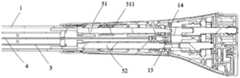
- Figure 1is a side cross-sectional view of the head portion of the stapler handle system according to an embodiment of the present invention
- Figure 2is a side cross-sectional view of the end portion of the stapler handle system according to an embodiment of the present invention
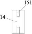
- FIG. 3is a schematic structural diagram of the area sensor in the stapler handle system according to an embodiment of the present invention.
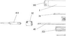
- Figure 4is a schematic structural view of the head end of the stapler handle system according to an embodiment of the present invention.
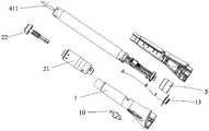
- Figure 5is a schematic diagram of the structure of the end of the stapler handle system shown in an embodiment of the present invention.
- 6 to 8are schematic diagrams of the structure of a tubular stapler according to an embodiment of the invention.
- connectionshould be understood in a broad sense unless otherwise clearly specified and limited.
- theycan be fixed or detachable.
- Connected or integrally connectedit can be a mechanical connection or an electrical connection; it can be directly connected or indirectly connected through an intermediate medium, and it can be the internal communication between two components.
- the specific meaning of the above-mentioned terms in the present inventioncan be understood in specific situations.
- the stapler handle system shown in an embodiment of the present inventionis used to connect with the end effector 2, which includes a working head 1, arranged in the working head 1 and used The firing assembly 3 fired at the driving end effector 2, the closing assembly 4 arranged in the working head 1 and for driving the end effector 2 to close, and the driving assembly (not shown) that connects and drives the firing assembly 3 and the closing assembly 4 Icon).
- the working head 1includes an opposite end (in the direction indicated by arrow A in Fig. 1) and a head end (in the opposite direction to the direction indicated by arrow A in Fig. 1), and an end effector is provided at its head end.
- the drive assemblyis arranged at the end, and it connects and drives the closing assembly 4 to move toward the end or the head end relative to the working head 1 (close to or away from the end effector 2).
- the drive assemblyincludes a drive motor (not shown) for providing drive power.
- the drive motorhas a safe torque range. When the closing assembly 4 moves toward the end and the drive motor runs beyond the safe torque range, the drive assembly stops driving to close The component 4 moves to the end to avoid the excessive pressing force from pinching the tissue.
- the stapler handle system of the present inventionfurther includes an operation button 10 arranged on the outer surface of the working head 1 and a control circuit 13 arranged therein.
- the control circuit 13is electrically connected to the driving assembly and the operation button 10.
- a firing identification zone 14is also provided inside the working head 1.
- the firing identification zone 14is arranged on the end side of the closing assembly 4, and the closing assembly 4 is provided with a firing identification section (not labeled) that cooperates with the firing identification zone 14 .
- the working head 1is provided with an area sensor 15 which is arranged at the end of the working head 1 and fixed on a support frame (not shown).
- the area sensor 15includes at least two position sensors 151. The interval area between the two position sensors 151 is defined as the firing recognition area 14.
- the area sensor 15transmits a signal ⁇ Control circuit 13. It is true that in other embodiments, the firing recognition area 14 can be observed by setting a window on the working head 1, or by setting vibrations, prompt sounds, etc., so that the user knows that the closure assembly 4 is in the firing recognition area 14. in.
- the drive assembly of the present inventionalso includes an input shaft (not shown) connected to the drive motor and a transmission assembly (not shown) that connects the input shaft to the closing assembly 43 and the firing assembly 3.
- the connection mode of each structure of the drive assemblyis the present There are conventional means, which will not be explained here.
- the closing assemblyincludes a closing rod 41 for docking with the end effector and the driving assembly, and the firing recognition part is provided at the end of the closing rod 41.
- the firing assembly 3includes a firing rod 31 driven by the driving assembly and a firing ring 32 that is screwed to the firing rod 31.
- the number of the firing rod 31is two.
- the working head 1is also provided with a fixed bracket 1 which is formed by two symmetrically arranged elbow brackets 121.
- the two firing rods 31 in the firing assembly 3are respectively arranged on the upper and lower sides of the fixing bracket 12, and the closing assembly 4 It is set at the middle position of the fixed bracket 12, and the firing assembly 3 and the closing assembly 4 are mechanically connected with the fixed bracket 12.
- the firing rod 31is snap-connected with a firing piece 311 at its end.
- the firing piece 311 and the closing rod 41are disposed through the switching shaft 5, and the switching shaft 5 is inserted with the firing shaft 51 and the closing shaft respectively connecting the firing rod 31 and the closing rod 41.
- the firing shaft 51is provided with a firing shaft slider 511, and the firing shaft 51 and the closing shaft 52 are fixed on a sliding rail 53 connected to the driving assembly.
- the switching shaft 5also includes a bearing 54 connected with the firing shaft 51, a sleeve 55 connected with the closing shaft 52, and a shaft bracket 56 for fixing, which is an existing structure and will not be described here.
- the above-mentioned stapler handle systemcan be applied to different types of staplers, and a tubular stapler is taken as an example for description.
- the tubular stapler shown in an embodiment of the present inventionadopts the above-mentioned stapler handle system and is equipped with an end effector 2.
- the end effector 2includes a staple cartridge assembly 21 and a staple seat 22.
- the staple cartridge assembly 21is fixedly installed on the mounting portion 101.
- a piercing shaft 411is provided on the head end of the closing rod 41.
- the piercing shaft 411is connected to the staple
- the seat 22is driven by the closing rod 41 to move, so that the closing rod 41 drives the staple seat 22 to move relative to the staple cartridge assembly 21.
- the staple cartridge assembly 21includes a staple cartridge 211 for accommodating staples and a staple pusher 212 for pushing the staples, and the staple cartridge 211 is recessed with a cavity 213 for accommodating tissue.
- the firing ring 32is connected to the nail pusher 212 so that the firing rod 31 drives the nail pusher 212 to push the suture nails toward the nail seat 22.
- the tubular stapler of the present inventionmainly includes three systems: a closure system, a firing system, and an end effector: a closure system: a puncture shaft 413, a closure rod 41 connected to the puncture shaft 413, a closure shaft 52 connected to the closure rod 41, and
- the driving component and the transmission deviceare composed;
- the firing systemconsists of a firing ring 32, a firing rod 31 connected with the firing ring 32, a firing shaft 51 connected with the firing rod 31, and a driving component and a transmission device;
- the end effectora nail
- the seat 22 and the staple cartridge assembly 21are composed.
- the working principle of the tubular stapleris:
- the end effector 2is in the open state, and the staple holder 22 is separated from the staple cartridge assembly 21, and then the user manipulates the operating button 10 to cause the drive assembly to drive the closing rod 41 to drive the staple holder 22 to the end direction (stap cartridge assembly 21 direction) during the closing process, when the tissue is clamped, the driving force for driving the closing rod 41 to move and the operating torque of the driving motor gradually increase.
- it exceeds the set safe torque rangeit will automatically stop working , So that the closing rod 41 stops moving, and then it is judged whether the firing recognition part is in the firing recognition area 14 (that is, whether the firing distance requirement is satisfied), and then it is determined whether the firing is completed.
- the firing recognition portion at the end of the closing rod 41is in the firing recognition zone 14 and the driving motor is in the safe torque range. At this time, the firing can be completed by manipulating the operating button 10.
- the drive motorexceeds the safe torque range, and at the same time, the end of the closing rod 41 cannot reach the firing identification zone 14, so that the tubular stapler cannot be triggered to protect the tissue.
- the stapler handle system and the stapler of the present inventiondrive the closing assembly and the firing assembly by using a drive motor set with a safe torque range.
- the drive motordrives the closing assembly to close (moving to the end direction)
- the drive motorruns beyond its set safe torque range, it will automatically stop working to stop the closing component from moving, and then determine whether the firing recognition part is in the firing recognition area (that is, whether the firing distance requirement is met) to determine whether to complete Fired. Therefore, the stapler handle system and the stapler can simultaneously control the tissue squeezing force and the closing distance in the process of squeezing the tissue, avoiding problems such as tissue damage and poor nailing effect due to inconsistent end effector squeezing force.
Landscapes
- Health & Medical Sciences (AREA)
- Life Sciences & Earth Sciences (AREA)
- Surgery (AREA)
- Heart & Thoracic Surgery (AREA)
- Engineering & Computer Science (AREA)
- Biomedical Technology (AREA)
- Nuclear Medicine, Radiotherapy & Molecular Imaging (AREA)
- Medical Informatics (AREA)
- Molecular Biology (AREA)
- Animal Behavior & Ethology (AREA)
- General Health & Medical Sciences (AREA)
- Public Health (AREA)
- Veterinary Medicine (AREA)
- Surgical Instruments (AREA)
- Portable Nailing Machines And Staplers (AREA)
Abstract
Description
Translated fromChinese本申请要求了申请日为2019年1月24日,申请号为201910067900.0的中国专利申请的优先权,其全部内容通过引用结合在本申请中。This application claims the priority of the Chinese patent application whose application date is January 24, 2019 and the application number is 201910067900.0, the entire content of which is incorporated into this application by reference.
本发明涉及一种吻合器手柄系统及吻合器,属于医疗设备领域。The invention relates to a stapler handle system and a stapler, belonging to the field of medical equipment.
吻合器适用于中食道、胃、十二指肠、小肠、结肠及直肠等吻合时使用。特别适用于显露和操作困难的食道、胃吻合和中段直肠癌切除后结肠直肠低位端端吻合术,是目前在重建手术中已普遍采用的一种外科手术器械。该产品采用订书机原理,通过延管状周边二排呈交错排列的吻合针,在手术中对脏器进行吻合对接。吻合器具有吻合口径大小一致,粘膜对合整齐,吻合口牢度可靠,止血效果及血运保持良好以及吻合切除一次完成,操作方便的优点。不仅可大大缩短手术时间,减少出血量,手术创伤轻,并可提高手术质量,减少手术并发症。The stapler is suitable for anastomosis of the middle esophagus, stomach, duodenum, small intestine, colon and rectum. It is especially suitable for esophagus, gastric anastomosis, and colorectal low end-to-end anastomosis after resection of middle rectal cancer, which is difficult to expose and operate. It is a surgical instrument commonly used in reconstructive surgery. The product adopts the principle of stapler, through two rows of staggered anastomotic needles along the periphery of the tube, the organs are anastomosed and docked during the operation. The stapler has the advantages of uniform anastomotic caliber, neat mucosal alignment, reliable anastomotic fastness, good hemostatic effect and blood supply maintenance, complete anastomosis resection at one time, and convenient operation. Not only can the operation time be greatly shortened, the amount of bleeding is reduced, the surgical trauma is light, the quality of the operation can be improved, and the complications of the operation can be reduced.
现有的吻合器的工作方式为通过将组织压缩在抵钉座和钉仓面之间并适当保压后,分布在圆周上的缝合钉同时被推钉片推出,将处于钳口之间的组织缝合并切断肠管内部的组织。然而,在压榨组织的过程中,往往是人为或电动的控制压榨后的距离。因为目前的器械只控制压榨后的距离,所以对于不同厚度的组织可能会导致压榨力不一致。可能压榨力较大导致过压,把组织压烂。也可能压榨力不足,导致成钉时组织位移,最终达不到较好的吻合效果。The working method of the existing stapler is to compress the tissue between the staple seat and the staple cartridge surface and properly maintain the pressure, and the suture staples distributed on the circumference are pushed out by the staple pusher at the same time, which will be between the jaws. The tissue sutures and cuts the tissue inside the intestine. However, in the process of squeezing tissues, the distance after squeezing is often controlled artificially or electrically. Because the current equipment only controls the distance after pressing, it may cause inconsistent pressing force for tissues of different thicknesses. It is possible that the squeezing force is too large and the tissue is crushed. It is also possible that the pressing force is insufficient, resulting in the displacement of the tissue during nail formation, and a good anastomosis effect cannot be finally achieved.
发明内容Summary of the invention
本发明的目的在于提供一种吻合器手柄系统及吻合器,在压榨组织的过程中能同时控制组织压榨力和闭合距离,避免因为端部执行器压力不一致而导致出现组织受损、成钉效果差等问题。The purpose of the present invention is to provide a stapler handle system and stapler, which can simultaneously control the tissue squeezing force and closing distance during tissue squeezing, so as to avoid tissue damage and nailing effects caused by inconsistent end effector pressure Poor and other issues.
为达到上述目的,本发明提供如下技术方案:一种吻合器手柄系统,用于与端部执行器连接,所述吻合器手柄系统包括工作头、设置在所述工作头内且 用于驱动所述端部执行器击发的击发组件、设置在所述工作头内且用于驱使所述端部执行器闭合的闭合组件,以及连接并驱动所述击发组件和闭合组件的驱动组件,所述工作头包括相对设置的末端和头端,所述头端设有用于安装所述端部执行器的安装部,所述驱动组件设置在所述末端,连接并驱动所述闭合组件相对于所述工作头朝所述末端或头端方向移动;所述驱动组件包括用于提供驱动力的驱动电机,所述驱动电机设有安全扭矩范围,当所述闭合组件朝向所述末端方向移动,且所述驱动电机运转超过所述安全扭矩范围时,所述驱动组件停止驱动所述闭合组件向所述末端移动。In order to achieve the above objective, the present invention provides the following technical solutions: a stapler handle system for connecting with an end effector, the stapler handle system includes a working head, arranged in the working head and used to drive the The firing assembly for firing the end effector, the closing assembly arranged in the working head and for driving the end effector to close, and the driving assembly connecting and driving the firing assembly and the closing assembly, the work The head includes opposite ends and a head end, the head end is provided with a mounting part for installing the end effector, the drive assembly is arranged at the end, and connects and drives the closing assembly relative to the working The head moves toward the end or the direction of the head end; the drive assembly includes a drive motor for providing driving force, the drive motor is provided with a safe torque range, when the closing assembly moves toward the end direction, and the When the driving motor runs beyond the safe torque range, the driving assembly stops driving the closing assembly to move to the end.
进一步地,所述工作头内设置有击发识别区,所述闭合组件上设置有与所述击发识别区配合的击发识别部。Further, a firing recognition area is provided in the working head, and a firing recognition part that cooperates with the firing recognition area is provided on the closing assembly.
进一步地,所述工作头内还设有区域感应器和控制电路,所述区域感应器设置在所述工作头的末端处,所述区域感应器具有识别区域,定义为所述击发识别区,当所述击发识别部处于所述击发识别区内时,所述区域感应器传递信号给所述控制电路。Further, the working head is also provided with an area sensor and a control circuit, the area sensor is arranged at the end of the working head, the area sensor has a recognition area, which is defined as the firing recognition area, When the firing identification part is in the firing identification zone, the area sensor transmits a signal to the control circuit.
进一步地,所述闭合组件包括用于与所述端部执行器和所述驱动组件对接的闭合杆,所述击发识别部设置在所述闭合杆的末端。Further, the closing assembly includes a closing rod for docking with the end effector and the driving assembly, and the firing recognition part is provided at the end of the closing rod.
进一步地,所述工作头内还设有固定支架,所述击发组件和闭合组件设置在所述固定支架上。Further, a fixing bracket is also provided in the working head, and the firing assembly and the closing assembly are arranged on the fixing bracket.
进一步地,所述固定支架包括两个对称设置的弯管支架,所述闭合组件设置在两个所述弯管支架之间。Further, the fixed bracket includes two symmetrically arranged elbow brackets, and the closing component is arranged between the two elbow brackets.
进一步地,所述击发组件包括设置在所述弯管支架上击发杆以及与所述击发杆螺旋配接的击发环。Further, the firing assembly includes a firing rod arranged on the elbow bracket and a firing ring spirally connected with the firing rod.
本发明还提供了一种吻合器,其包括端部执行器和所述的吻合器手柄系统,所述端部执行器包括钉仓组件和抵钉座,所述钉仓组件固定安装在所述安装部上,所述钉仓组件包括用于容置缝合钉的钉仓和用于推钉的推钉片,所述推钉片与所述击发杆连接,以将所述缝合钉朝向抵钉座推出。The present invention also provides a stapler, which includes an end effector and the stapler handle system, the end effector includes a staple cartridge assembly and a staple seat, and the staple cartridge assembly is fixedly installed on the On the mounting part, the staple cartridge assembly includes a staple cartridge for accommodating suture nails and a nail pushing piece for pushing the nails, and the nail pushing piece is connected with the firing rod to direct the suture nails toward the nail. Block launch.
进一步地,所述闭合杆上设有穿刺轴,所述穿刺轴连接所述抵钉座,以使所述闭合杆带动所述抵钉座相对于钉仓组件移动。Further, a puncture shaft is provided on the closing rod, and the puncture shaft is connected to the nail abutment base, so that the closure rod drives the nail abutment base to move relative to the staple cartridge assembly.
与现有技术相比,本发明的有益效果在于:本发明的吻合器手柄系统及吻合器通过采用设定有安全扭矩范围的驱动电机对闭合组件和击发组件进行驱动,当驱动电机驱动闭合组件进行闭合(向末端方向移动)时,若驱动电机运转超过其设定的安全扭矩范围后会自动停止工作,以使闭合组件停止移动,然后判断击发识别部是否在击发识别区内,(即判断是否满足击发距离要求)决定是否完成击发。故,该吻合器手柄系统及吻合器在压榨组织的过程中能同时控制组织压榨力和闭合距离,避免因为端部执行器压榨力不一致而导致出现组织受损、成钉效果差等问题。Compared with the prior art, the beneficial effect of the present invention is that the stapler handle system and the stapler of the present invention drive the closing assembly and the firing assembly by using a drive motor set with a safe torque range. When the drive motor drives the closing assembly When closing (moving to the end direction), if the drive motor runs beyond its set safe torque range, it will automatically stop working to stop the closing component from moving, and then determine whether the firing recognition part is in the firing recognition zone, (that is, judge Whether to meet the firing distance requirements) decide whether to complete the firing. Therefore, the stapler handle system and the stapler can simultaneously control the tissue squeezing force and the closing distance in the process of squeezing the tissue, and avoid problems such as tissue damage and poor nailing effect caused by inconsistent end effector squeezing force.
上述说明仅是本发明技术方案的概述,为了能够更清楚了解本发明的技术手段,并可依照说明书的内容予以实施,以下以本发明的较佳实施例并配合附图详细说明如后。The above description is only an overview of the technical solution of the present invention. In order to understand the technical means of the present invention more clearly and implement it in accordance with the content of the description, the preferred embodiments of the present invention are described in detail below with the accompanying drawings.
图1为本发明一实施例所示的吻合器手柄系统的头端部分的侧面剖视图;Figure 1 is a side cross-sectional view of the head portion of the stapler handle system according to an embodiment of the present invention;
图2为本发明一实施例所示的吻合器手柄系统的末端部分的侧面剖视图;Figure 2 is a side cross-sectional view of the end portion of the stapler handle system according to an embodiment of the present invention;
图3为本发明一实施例所示的吻合器手柄系统中的区域感应器的结构示意图;3 is a schematic structural diagram of the area sensor in the stapler handle system according to an embodiment of the present invention;
图4为本发明一实施例所示的吻合器手柄系统的头端的结构示意图;Figure 4 is a schematic structural view of the head end of the stapler handle system according to an embodiment of the present invention;
图5为本发明一实施例所示的吻合器手柄系统的末端的结构示意图;Figure 5 is a schematic diagram of the structure of the end of the stapler handle system shown in an embodiment of the present invention;
图6至图8为本发明一实施例所示的管型吻合器的结构示意图。6 to 8 are schematic diagrams of the structure of a tubular stapler according to an embodiment of the invention.
下面结合附图和实施例,对本发明的具体实施方式作进一步详细描述。以下实施例用于说明本发明,但不用来限制本发明的范围。The specific embodiments of the present invention will be described in further detail below in conjunction with the drawings and embodiments. The following examples are used to illustrate the present invention, but not to limit the scope of the present invention.
在本发明的描述中,需要说明的是,术语“中心”、“上”、“下”、“左”、“右”、“前”、“后”、“轴线方向”、“内”、“外”等指示的方位或位置关系为基于附图所示的方位或位置关系,仅是为了便于描述本发明和简化描述,而不是指示或 暗示所指的装置或元件必须具有特定的方位、以特定的方位构造和操作,因此不能理解为对本发明的限制。此外,术语“第一”、“第二”、“第三”仅用于描述目的,而不能理解为指示或暗示相对重要性。In the description of the present invention, it should be noted that the terms "center", "upper", "lower", "left", "right", "front", "rear", "axis direction", "inner", The orientation or positional relationship indicated by "outside" is based on the orientation or positional relationship shown in the drawings, and is only for the convenience of describing the present invention and simplifying the description, and does not indicate or imply that the device or element referred to must have a specific orientation, It is constructed and operated in a specific orientation, so it cannot be understood as a limitation to the present invention. In addition, the terms "first", "second", and "third" are only used for descriptive purposes, and cannot be understood as indicating or implying relative importance.
在本发明的描述中,需要说明的是,除非另有明确的规定和限定,术语“安装”、“相连”、“连接”应做广义理解,例如,可以是固定连接,也可以是可拆卸连接,或一体地连接;可以是机械连接,也可以是电连接;可以是直接相连,也可以通过中间媒介间接相连,可以是两个元件内部的连通。对于本领域的普通技术人员而言,可以具体情况理解上述术语在本发明中的具体含义。In the description of the present invention, it should be noted that the terms "installation", "connection" and "connection" should be understood in a broad sense unless otherwise clearly specified and limited. For example, they can be fixed or detachable. Connected or integrally connected; it can be a mechanical connection or an electrical connection; it can be directly connected or indirectly connected through an intermediate medium, and it can be the internal communication between two components. For those of ordinary skill in the art, the specific meaning of the above-mentioned terms in the present invention can be understood in specific situations.
此外,下面所描述的本发明不同实施方式中所涉及的技术特征只要彼此之间未构成冲突就可以相互结合。In addition, the technical features involved in the different embodiments of the present invention described below can be combined with each other as long as they do not conflict with each other.
请参见图1至图5,本发明一实施例所示的吻合器手柄系统,该吻合器手柄系统用于与端部执行器2连接,其包括工作头1、设置在工作头1内且用于驱动端部执行器2击发的击发组件3、设置在工作头1内且用于驱使端部执行器2闭合的闭合组件4,以及连接并驱动击发组件3和闭合组件4的驱动组件(未图示)。具体的,工作头1包括相对设置的末端(图1中箭头A所指方向)和头端(图1中与箭头A所指相反的方向),在其头端设有用于安装端部执行器2的安装部101,驱动组件设置在末端,其连接并驱动闭合组件4相对于工作头1朝末端或头端方向(靠近或远离端部执行器2)移动。驱动组件包括用于提供驱动力的驱动电机(未图示),该驱动电机设有安全扭矩范围,当闭合组件4朝向末端方向移动,且驱动电机运转超过安全扭矩范围时,驱动组件停止驱动闭合组件4向末端移动,以避免压榨力过大夹伤组织。1 to 5, the stapler handle system shown in an embodiment of the present invention, the stapler handle system is used to connect with the
本发明的吻合器手柄系统还包括设置在工作头1外表面上的操作按钮10,以及设置在其内的控制电路13,控制电路13与驱动组件和操作按钮10电连接。在工作头1的内部还设置有击发识别区14,击发识别区14设置在闭合组件4的末端一侧,且闭合组件4上设置有与该击发识别区14配合的击发识别部(未标号)。具体的,工作头1内设有区域感应器15,区域感应器15设置在工作头1的末端处,并固定在支撑架(未图示)上。该区域感应器15包括至少两个位置 感应器151,两个位置感应器151之间的间隔区域定义为击发识别区14,当击发识别部处于击发识别区14内时,区域感应器15传递信号给控制电路13。诚然,在其他实施例中,击发识别区14可以通过在工作头1上设置视窗进行观察,或者,通过设置震动、提示音等方式进行提示,以使使用者知晓闭合组件4处于击发识别区14中。The stapler handle system of the present invention further includes an
本发明的驱动组件还包括连接驱动电机的输入轴(未图示)和连接该输入轴与闭合组件43及击发组件3的传动组件(未图示),该驱动组件各结构的连接方式为现有常规手段,在此不进行阐述。The drive assembly of the present invention also includes an input shaft (not shown) connected to the drive motor and a transmission assembly (not shown) that connects the input shaft to the closing assembly 43 and the firing
在本发明中,闭合组件包括用于与所述端部执行器和所述驱动组件对接的闭合杆41,击发识别部设置在闭合杆41的末端处。击发组件3包括由驱动组件驱动的击发杆31以及与击发杆31螺旋配接的击发环32,在本实施例中,击发杆31的数量为两个,诚然,在其他实施例中,其数量可根据实际需要进行选择。在工作头1内还设有固定支架1,其通过两个对称设置的弯管支架121形成,击发组件3中的两个击发杆31分别设置在该固定支架12的上下两侧,闭合组件4则是设置在固定支架12的中间位置上,并且击发组件3和闭合组件4与固定支架12机械连接。击发杆31在其末端卡扣式连接有击发片311,击发片311和闭合杆41穿过切换轴5设置,切换轴5内插入有分别连接击发杆31和闭合杆41的击发轴51和闭合轴52,且击发轴51上设有击发轴滑块511,击发轴51和闭合轴52固定在与驱动组件连接的滑轨53上。切换轴5还包括与击发轴51连接的轴承54、与闭合轴52连接的轴套55,以及起固定作用的轴架56,其为现有结构,在此不再阐述。In the present invention, the closing assembly includes a closing
本发明中,上述的吻合器手柄系统可应用于不同种类的吻合器,在此以管型吻合器为例进行说明。In the present invention, the above-mentioned stapler handle system can be applied to different types of staplers, and a tubular stapler is taken as an example for description.
请结合图6至图8,本发明一实施例所示的管型吻合器,其采用上述的吻合器手柄系统并安装有端部执行器2。具体的,端部执行器2包括钉仓组件21和抵钉座22,钉仓组件21固定安装在安装部101上,闭合杆41的头端上设有穿刺轴411,穿刺轴411连接抵钉座22并由闭合杆41驱使运动,以使闭合杆41 带动抵钉座22相对于钉仓组件21移动。钉仓组件21包括用于容置缝合钉的钉仓211和用于推钉的推钉片212,并且订仓211内凹形成有用于容置组织的空腔213。击发环32与该推钉片212连接,以使击发杆31带动推钉片212将缝合钉朝向抵钉座22的方向推出。Referring to FIGS. 6 to 8, the tubular stapler shown in an embodiment of the present invention adopts the above-mentioned stapler handle system and is equipped with an
本发明的管型吻合器主要包括闭合系统、击发系统和端部执行器三个系统:闭合系统:由穿刺轴413、连接穿刺轴413的闭合杆41、与闭合杆41连接的闭合轴52以及驱动组件和传动装置组成;击发系统:由击发环32、与击发环32连接的击发杆31、与击发杆31连接的击发轴51以及驱动组件和传动装置组成;端部执行器:由抵钉座22和钉仓组件21组成。该管型吻合器的工作原理为:The tubular stapler of the present invention mainly includes three systems: a closure system, a firing system, and an end effector: a closure system: a puncture shaft 413, a
初始时,端部执行器2处于打开状态,抵钉座22与钉仓组件21分离,随后使用者通过操控操作按钮10使驱动组件驱动闭合杆41带动抵钉座22向末端方向(钉仓组件21方向)移动,在该闭合过程中,当夹闭到组织后,驱动闭合杆41移动的驱动力以及驱动电机的运转扭矩逐渐增加,当其超过所设定的安全扭矩范围后会自动停止工作,以使闭合杆41停止移动,然后判断击发识别部是否在击发识别区14内(即判断是否满足击发距离要求),再决定是否完成击发。当所压榨的组织为正常厚度时,闭合杆41末端的击发识别部处于击发识别区14内,且驱动电机处于安全扭矩范围,此时通过操控操作按钮10即可完成击发。而当所压榨的组织较厚时,驱动电机超出安全扭矩范围,同时,闭合杆41的末端无法到达击发识别区14内,使该管型吻合器不能触动击发,以起到保护组织的作用。该设计方法能保证组织压榨牢固,避免出现因为压榨力不够而导致成钉时组织位移、成钉效果差等情况。Initially, the
综上所述:本发明的吻合器手柄系统及吻合器通过采用设定有安全扭矩范围的驱动电机对闭合组件和击发组件进行驱动,当驱动电机驱动闭合组件进行闭合(向末端方向移动)时,若驱动电机运转超过其设定的安全扭矩范围后会自动停止工作,以使闭合组件停止移动,然后判断击发识别部是否在击发识别区内,(即判断是否满足击发距离要求)决定是否完成击发。故,该吻合器手柄系统及吻合器在压榨组织的过程中能同时控制组织压榨力和闭合距离,避免因 为端部执行器压榨力不一致而导致出现组织受损、成钉效果差等问题。To sum up: the stapler handle system and the stapler of the present invention drive the closing assembly and the firing assembly by using a drive motor set with a safe torque range. When the drive motor drives the closing assembly to close (moving to the end direction) , If the drive motor runs beyond its set safe torque range, it will automatically stop working to stop the closing component from moving, and then determine whether the firing recognition part is in the firing recognition area (that is, whether the firing distance requirement is met) to determine whether to complete Fired. Therefore, the stapler handle system and the stapler can simultaneously control the tissue squeezing force and the closing distance in the process of squeezing the tissue, avoiding problems such as tissue damage and poor nailing effect due to inconsistent end effector squeezing force.
以上所述实施例的各技术特征可以进行任意的组合,为使描述简洁,未对上述实施例中的各个技术特征所有可能的组合都进行描述,然而,只要这些技术特征的组合不存在矛盾,都应当认为是本说明书记载的范围。The technical features of the above-mentioned embodiments can be combined arbitrarily. To make the description concise, all possible combinations of the various technical features in the above-mentioned embodiments are not described. However, as long as there is no contradiction in the combination of these technical features, All should be considered as the scope of this specification.
以上所述实施例仅表达了本发明的几种实施方式,其描述较为具体和详细,但并不能因此而理解为对发明专利范围的限制。应当指出的是,对于本领域的普通技术人员来说,在不脱离本发明构思的前提下,还可以做出若干变形和改进,这些都属于本发明的保护范围。因此,本发明专利的保护范围应以所附权利要求为准。The above-mentioned embodiments only express several embodiments of the present invention, and the descriptions are more specific and detailed, but they should not be interpreted as a limitation on the scope of the invention patent. It should be pointed out that for those of ordinary skill in the art, without departing from the concept of the present invention, several modifications and improvements can be made, and these all fall within the protection scope of the present invention. Therefore, the protection scope of the patent of the present invention should be subject to the appended claims.
Claims (9)
Translated fromChineseApplications Claiming Priority (2)
| Application Number | Priority Date | Filing Date | Title |
|---|---|---|---|
| CN201910067900.0ACN111466985A (en) | 2019-01-24 | 2019-01-24 | Anastomat handle system and anastomat |
| CN201910067900.0 | 2019-01-24 |
Publications (1)
| Publication Number | Publication Date |
|---|---|
| WO2020151343A1true WO2020151343A1 (en) | 2020-07-30 |
Family
ID=71736513
Family Applications (1)
| Application Number | Title | Priority Date | Filing Date |
|---|---|---|---|
| PCT/CN2019/118719CeasedWO2020151343A1 (en) | 2019-01-24 | 2019-11-15 | Stapler handle system and stapler |
Country Status (2)
| Country | Link |
|---|---|
| CN (1) | CN111466985A (en) |
| WO (1) | WO2020151343A1 (en) |
Citations (9)
| Publication number | Priority date | Publication date | Assignee | Title |
|---|---|---|---|---|
| CN102048567A (en)* | 2009-10-05 | 2011-05-11 | Tyco医疗健康集团 | Battery ejection design for a surgical device |
| CN103622727A (en)* | 2013-06-26 | 2014-03-12 | 任莹 | Electric intelligent surgical anastomat |
| CN105411641A (en)* | 2015-12-22 | 2016-03-23 | 苏州英途康医疗科技有限公司 | Anastomat |
| CN105476678A (en)* | 2015-12-22 | 2016-04-13 | 苏州英途康医疗科技有限公司 | Linear cutting anastomat |
| CN105596046A (en)* | 2015-12-22 | 2016-05-25 | 苏州英途康医疗科技有限公司 | Anastomat |
| CN206424111U (en)* | 2016-09-28 | 2017-08-22 | 姜永胜 | The circular nail type stapler of anastomosed tissue blood fortune can be monitored in real time |
| US20180116667A1 (en)* | 2016-10-31 | 2018-05-03 | Bnr Co., Ltd. | Circular stapler |
| CN108113725A (en)* | 2017-12-21 | 2018-06-05 | 苏州英途康医疗科技有限公司 | Stapler control method and stapler |
| CN209661716U (en)* | 2019-01-24 | 2019-11-22 | 苏州英途康医疗科技有限公司 | Stapler handle system and stapler |
Family Cites Families (5)
| Publication number | Priority date | Publication date | Assignee | Title |
|---|---|---|---|---|
| US8459525B2 (en)* | 2008-02-14 | 2013-06-11 | Ethicon Endo-Sugery, Inc. | Motorized surgical cutting and fastening instrument having a magnetic drive train torque limiting device |
| US8490850B2 (en)* | 2011-04-29 | 2013-07-23 | Covidien Lp | Circular stapler with controlled tissue compression |
| US10194911B2 (en)* | 2015-06-26 | 2019-02-05 | Ethicon Llc | Surgical stapler with ready state indicator |
| CN105395232B (en)* | 2015-12-22 | 2019-02-15 | 苏州英途康医疗科技有限公司 | Electric stapler |
| KR102760033B1 (en)* | 2016-01-29 | 2025-02-03 | 인튜어티브 서지컬 오퍼레이션즈 인코포레이티드 | Systems and methods for variable speed surgical devices |
- 2019
- 2019-01-24CNCN201910067900.0Apatent/CN111466985A/enactivePending
- 2019-11-15WOPCT/CN2019/118719patent/WO2020151343A1/ennot_activeCeased
Patent Citations (9)
| Publication number | Priority date | Publication date | Assignee | Title |
|---|---|---|---|---|
| CN102048567A (en)* | 2009-10-05 | 2011-05-11 | Tyco医疗健康集团 | Battery ejection design for a surgical device |
| CN103622727A (en)* | 2013-06-26 | 2014-03-12 | 任莹 | Electric intelligent surgical anastomat |
| CN105411641A (en)* | 2015-12-22 | 2016-03-23 | 苏州英途康医疗科技有限公司 | Anastomat |
| CN105476678A (en)* | 2015-12-22 | 2016-04-13 | 苏州英途康医疗科技有限公司 | Linear cutting anastomat |
| CN105596046A (en)* | 2015-12-22 | 2016-05-25 | 苏州英途康医疗科技有限公司 | Anastomat |
| CN206424111U (en)* | 2016-09-28 | 2017-08-22 | 姜永胜 | The circular nail type stapler of anastomosed tissue blood fortune can be monitored in real time |
| US20180116667A1 (en)* | 2016-10-31 | 2018-05-03 | Bnr Co., Ltd. | Circular stapler |
| CN108113725A (en)* | 2017-12-21 | 2018-06-05 | 苏州英途康医疗科技有限公司 | Stapler control method and stapler |
| CN209661716U (en)* | 2019-01-24 | 2019-11-22 | 苏州英途康医疗科技有限公司 | Stapler handle system and stapler |
Also Published As
| Publication number | Publication date |
|---|---|
| CN111466985A (en) | 2020-07-31 |
Similar Documents
| Publication | Publication Date | Title |
|---|---|---|
| US11399830B2 (en) | Controlled tissue compression systems and methods | |
| EP3320859B1 (en) | Circular surgical stapler with angularly asymmetric deck features | |
| US10603042B2 (en) | Flexible circular stapler | |
| US20130105550A1 (en) | Surgical stapling apparatus | |
| BR112020003029B1 (en) | surgical instrument | |
| CN104434245B (en) | End effector, surgical operating instrument and purse-string forceps | |
| CN118105118B (en) | Surgical instrument, guide assembly thereof and detaching tool | |
| WO2020151342A1 (en) | Stapler handle system and stapler | |
| CN112754566B (en) | A minimally invasive endoscopic stapler that can be fired when the head is deflected | |
| CN213189866U (en) | Electric pushing device for triggering anastomat | |
| WO2020151341A1 (en) | Stapler handle system and stapler | |
| CN115944338A (en) | Nail bin assembly for surgical instrument and surgical instrument | |
| WO2020151343A1 (en) | Stapler handle system and stapler | |
| CN111317535B (en) | Circular tube type anastomat | |
| CN2889184Y (en) | An alimentary tract anastomat | |
| HK40034553A (en) | Anastomat handle system and anastomat | |
| CN112089464B (en) | Jaw opening and closing device of laparoscopic stapler | |
| US11642133B2 (en) | Securing ring for use with an end-to-end anastomosis stapling device | |
| WO2023030042A1 (en) | Staple cartridge assembly and surgical instrument | |
| HK40034551B (en) | Anastomat handle system and anastomat | |
| HK40034551A (en) | Anastomat handle system and anastomat | |
| HK40034554A (en) | Anastomat handle system and anastomat | |
| HK40034554B (en) | Anastomat handle system and anastomat | |
| WO2022143721A1 (en) | Surgical stapler | |
| CN222929786U (en) | Linear cutting semi-closer |
Legal Events
| Date | Code | Title | Description |
|---|---|---|---|
| 121 | Ep: the epo has been informed by wipo that ep was designated in this application | Ref document number:19911399 Country of ref document:EP Kind code of ref document:A1 | |
| NENP | Non-entry into the national phase | Ref country code:DE | |
| 122 | Ep: pct application non-entry in european phase | Ref document number:19911399 Country of ref document:EP Kind code of ref document:A1 | |
| 122 | Ep: pct application non-entry in european phase | Ref document number:19911399 Country of ref document:EP Kind code of ref document:A1 |