WO2020148829A1 - Sensor material, sensor element, garment, measurement device, monitoring system, and program - Google Patents
Sensor material, sensor element, garment, measurement device, monitoring system, and programDownload PDFInfo
- Publication number
- WO2020148829A1 WO2020148829A1PCT/JP2019/001101JP2019001101WWO2020148829A1WO 2020148829 A1WO2020148829 A1WO 2020148829A1JP 2019001101 WJP2019001101 WJP 2019001101WWO 2020148829 A1WO2020148829 A1WO 2020148829A1
- Authority
- WO
- WIPO (PCT)
- Prior art keywords
- clothing
- unit
- inductance
- sensor
- user
- Prior art date
- Legal status (The legal status is an assumption and is not a legal conclusion. Google has not performed a legal analysis and makes no representation as to the accuracy of the status listed.)
- Ceased
Links
Images


Classifications
- A—HUMAN NECESSITIES
- A61—MEDICAL OR VETERINARY SCIENCE; HYGIENE
- A61B—DIAGNOSIS; SURGERY; IDENTIFICATION
- A61B5/00—Measuring for diagnostic purposes; Identification of persons
- A61B5/103—Measuring devices for testing the shape, pattern, colour, size or movement of the body or parts thereof, for diagnostic purposes
- A61B5/11—Measuring movement of the entire body or parts thereof, e.g. head or hand tremor or mobility of a limb
- A61B5/113—Measuring movement of the entire body or parts thereof, e.g. head or hand tremor or mobility of a limb occurring during breathing
- A—HUMAN NECESSITIES
- A41—WEARING APPAREL
- A41D—OUTERWEAR; PROTECTIVE GARMENTS; ACCESSORIES
- A41D13/00—Professional, industrial or sporting protective garments, e.g. surgeons' gowns or garments protecting against blows or punches
- A41D13/12—Surgeons' or patients' gowns or dresses
- A41D13/1236—Patients' garments
- A41D13/1281—Patients' garments with incorporated means for medical monitoring
- A—HUMAN NECESSITIES
- A61—MEDICAL OR VETERINARY SCIENCE; HYGIENE
- A61B—DIAGNOSIS; SURGERY; IDENTIFICATION
- A61B5/00—Measuring for diagnostic purposes; Identification of persons
- A61B5/02—Detecting, measuring or recording for evaluating the cardiovascular system, e.g. pulse, heart rate, blood pressure or blood flow
- A61B5/0205—Simultaneously evaluating both cardiovascular conditions and different types of body conditions, e.g. heart and respiratory condition
- A—HUMAN NECESSITIES
- A61—MEDICAL OR VETERINARY SCIENCE; HYGIENE
- A61B—DIAGNOSIS; SURGERY; IDENTIFICATION
- A61B5/00—Measuring for diagnostic purposes; Identification of persons
- A61B5/103—Measuring devices for testing the shape, pattern, colour, size or movement of the body or parts thereof, for diagnostic purposes
- A61B5/11—Measuring movement of the entire body or parts thereof, e.g. head or hand tremor or mobility of a limb
- A61B5/1126—Measuring movement of the entire body or parts thereof, e.g. head or hand tremor or mobility of a limb using a particular sensing technique
- A—HUMAN NECESSITIES
- A61—MEDICAL OR VETERINARY SCIENCE; HYGIENE
- A61B—DIAGNOSIS; SURGERY; IDENTIFICATION
- A61B5/00—Measuring for diagnostic purposes; Identification of persons
- A61B5/48—Other medical applications
- A61B5/4806—Sleep evaluation
- A61B5/4818—Sleep apnoea
- A—HUMAN NECESSITIES
- A61—MEDICAL OR VETERINARY SCIENCE; HYGIENE
- A61B—DIAGNOSIS; SURGERY; IDENTIFICATION
- A61B5/00—Measuring for diagnostic purposes; Identification of persons
- A61B5/68—Arrangements of detecting, measuring or recording means, e.g. sensors, in relation to patient
- A61B5/6801—Arrangements of detecting, measuring or recording means, e.g. sensors, in relation to patient specially adapted to be attached to or worn on the body surface
- A61B5/6802—Sensor mounted on worn items
- A61B5/6804—Garments; Clothes
- D—TEXTILES; PAPER
- D02—YARNS; MECHANICAL FINISHING OF YARNS OR ROPES; WARPING OR BEAMING
- D02G—CRIMPING OR CURLING FIBRES, FILAMENTS, THREADS, OR YARNS; YARNS OR THREADS
- D02G3/00—Yarns or threads, e.g. fancy yarns; Processes or apparatus for the production thereof, not otherwise provided for
- D02G3/02—Yarns or threads characterised by the material or by the materials from which they are made
- D02G3/04—Blended or other yarns or threads containing components made from different materials
- D—TEXTILES; PAPER
- D02—YARNS; MECHANICAL FINISHING OF YARNS OR ROPES; WARPING OR BEAMING
- D02G—CRIMPING OR CURLING FIBRES, FILAMENTS, THREADS, OR YARNS; YARNS OR THREADS
- D02G3/00—Yarns or threads, e.g. fancy yarns; Processes or apparatus for the production thereof, not otherwise provided for
- D02G3/22—Yarns or threads characterised by constructional features, e.g. blending, filament/fibre
- D02G3/38—Threads in which fibres, filaments, or yarns are wound with other yarns or filaments, e.g. wrap yarns, i.e. strands of filaments or staple fibres are wrapped by a helically wound binder yarn
- G—PHYSICS
- G01—MEASURING; TESTING
- G01D—MEASURING NOT SPECIALLY ADAPTED FOR A SPECIFIC VARIABLE; ARRANGEMENTS FOR MEASURING TWO OR MORE VARIABLES NOT COVERED IN A SINGLE OTHER SUBCLASS; TARIFF METERING APPARATUS; MEASURING OR TESTING NOT OTHERWISE PROVIDED FOR
- G01D21/00—Measuring or testing not otherwise provided for
- G—PHYSICS
- G01—MEASURING; TESTING
- G01P—MEASURING LINEAR OR ANGULAR SPEED, ACCELERATION, DECELERATION, OR SHOCK; INDICATING PRESENCE, ABSENCE, OR DIRECTION, OF MOVEMENT
- G01P13/00—Indicating or recording presence, absence, or direction, of movement
- G—PHYSICS
- G01—MEASURING; TESTING
- G01P—MEASURING LINEAR OR ANGULAR SPEED, ACCELERATION, DECELERATION, OR SHOCK; INDICATING PRESENCE, ABSENCE, OR DIRECTION, OF MOVEMENT
- G01P15/00—Measuring acceleration; Measuring deceleration; Measuring shock, i.e. sudden change of acceleration
- A—HUMAN NECESSITIES
- A61—MEDICAL OR VETERINARY SCIENCE; HYGIENE
- A61B—DIAGNOSIS; SURGERY; IDENTIFICATION
- A61B2562/00—Details of sensors; Constructional details of sensor housings or probes; Accessories for sensors
- A61B2562/02—Details of sensors specially adapted for in-vivo measurements
- A61B2562/0219—Inertial sensors, e.g. accelerometers, gyroscopes, tilt switches
- A—HUMAN NECESSITIES
- A61—MEDICAL OR VETERINARY SCIENCE; HYGIENE
- A61B—DIAGNOSIS; SURGERY; IDENTIFICATION
- A61B2562/00—Details of sensors; Constructional details of sensor housings or probes; Accessories for sensors
- A61B2562/16—Details of sensor housings or probes; Details of structural supports for sensors
- A61B2562/164—Details of sensor housings or probes; Details of structural supports for sensors the sensor is mounted in or on a conformable substrate or carrier
- A—HUMAN NECESSITIES
- A61—MEDICAL OR VETERINARY SCIENCE; HYGIENE
- A61B—DIAGNOSIS; SURGERY; IDENTIFICATION
- A61B5/00—Measuring for diagnostic purposes; Identification of persons
- A61B5/0002—Remote monitoring of patients using telemetry, e.g. transmission of vital signals via a communication network
- A—HUMAN NECESSITIES
- A61—MEDICAL OR VETERINARY SCIENCE; HYGIENE
- A61B—DIAGNOSIS; SURGERY; IDENTIFICATION
- A61B5/00—Measuring for diagnostic purposes; Identification of persons
- A61B5/02—Detecting, measuring or recording for evaluating the cardiovascular system, e.g. pulse, heart rate, blood pressure or blood flow
- A61B5/024—Measuring pulse rate or heart rate
- A61B5/02438—Measuring pulse rate or heart rate with portable devices, e.g. worn by the patient
- A—HUMAN NECESSITIES
- A61—MEDICAL OR VETERINARY SCIENCE; HYGIENE
- A61B—DIAGNOSIS; SURGERY; IDENTIFICATION
- A61B5/00—Measuring for diagnostic purposes; Identification of persons
- A61B5/02—Detecting, measuring or recording for evaluating the cardiovascular system, e.g. pulse, heart rate, blood pressure or blood flow
- A61B5/024—Measuring pulse rate or heart rate
- A61B5/0245—Measuring pulse rate or heart rate by using sensing means generating electric signals, i.e. ECG signals
- A—HUMAN NECESSITIES
- A61—MEDICAL OR VETERINARY SCIENCE; HYGIENE
- A61B—DIAGNOSIS; SURGERY; IDENTIFICATION
- A61B5/00—Measuring for diagnostic purposes; Identification of persons
- A61B5/08—Measuring devices for evaluating the respiratory organs
- A61B5/085—Measuring impedance of respiratory organs or lung elasticity
- A61B5/086—Measuring impedance of respiratory organs or lung elasticity by impedance pneumography
- A—HUMAN NECESSITIES
- A61—MEDICAL OR VETERINARY SCIENCE; HYGIENE
- A61B—DIAGNOSIS; SURGERY; IDENTIFICATION
- A61B5/00—Measuring for diagnostic purposes; Identification of persons
- A61B5/103—Measuring devices for testing the shape, pattern, colour, size or movement of the body or parts thereof, for diagnostic purposes
- A61B5/11—Measuring movement of the entire body or parts thereof, e.g. head or hand tremor or mobility of a limb
- A61B5/1102—Ballistocardiography
- A—HUMAN NECESSITIES
- A61—MEDICAL OR VETERINARY SCIENCE; HYGIENE
- A61B—DIAGNOSIS; SURGERY; IDENTIFICATION
- A61B5/00—Measuring for diagnostic purposes; Identification of persons
- A61B5/74—Details of notification to user or communication with user or patient; User input means
- A61B5/7405—Details of notification to user or communication with user or patient; User input means using sound
Definitions
- the present inventionrelates to a sensor material, a sensor element, clothing, a measuring device, a monitoring system, and a program.
- a measuring devicethat easily detects human movement, respiration, heartbeat, and the like.
- a systemcapable of measuring and monitoring respiratory motions during sleep for determining whether or not an apnea syndrome, sudden death of a patient in a hospital or the like, prone death of an infant or the like.
- a system for detecting a person's breathing motion using a bed or the like provided with a sensor, a system for detecting a person's movement with a laser irradiation and an imaging device, and the likehave been known.
- the present inventionhas been made in view of these points, and an object thereof is to easily detect human movement, respiration, heartbeat, and the like.
- a sensor materialcomprising an insulating material which can be expanded and contracted in a longitudinal direction, and a conductive fiber which has conductivity and is wound around the insulating material in a coil shape.
- the conductive fibersmay be fixed to a plurality of different parts of the insulating material.
- the sensor material of the first aspect and a base body formed in a string shape or a band shape by using a thread that can expand and contract in the longitudinal directionare provided, and the sensor material is A sensor element is provided in which the sensor material is bonded to the substrate such that the substrate is stretchable in a stretchable direction.
- clothingincluding the sensor element according to the second aspect.
- the clothingis formed by using a stretchable cloth at least in part, the sensor material of the first aspect is bonded to the stretchable cloth, and the sensor material is stretchable.
- the clothmay be stretchable in any direction.
- the clothingmay further include connecting portions electrically connected to at least two portions of the conductive fiber.
- the one or more connecting portionsmay be a part of a button provided on the clothing.
- a fourth aspect of the present inventionbased on a measurement section that measures an inductance between two different connection sections among the plurality of connection sections of the clothing of the third aspect, and a measurement result of the inductance. And a specifying unit that specifies the state of the user wearing the clothes.
- the clothinghas a plurality of the connecting portions electrically connected to each of the three or more portions of the conductive fiber, and provides an electrical connection between the plurality of the connecting portions and the measuring portion.
- a switching unit that switches and a control unit that controls the switching unit to cause the measuring unit to respectively measure the inductance between the two adjacent connecting unitsmay be further provided.
- At least a part of the conductive fiberhas a fixing region fixed so as not to expand and contract with the expansion and contraction of the insulating material, and the clothing is electrically connected to each of two or more different parts of the fixing region.
- the measuring portionis a fixed area of the conductive fiber, with the inductance between two different connecting portions provided in the fixed area as a reference value. You may calculate the value of the inductance of a part other than.
- the clothingincludes an acceleration sensor for detecting an acceleration when the user wearing the clothing moves, and a gyro for detecting an angular velocity and/or an angular acceleration when the user wearing the clothing moves. At least one of the sensors may be further provided.
- a monitoring systemcomprising: an acquisition unit that acquires the states of a plurality of users who wear the plurality of clothes, and a detection unit that detects an abnormal state among the states of the plurality of users.
- the sixth aspect of the present inventionprovides a program that, when executed by a computer, causes the computer to function as at least a part of the monitoring system of the fifth aspect.
- the structural example of the monitoring system 10 which concerns on this embodimentis shown.
- the structural example of the clothing 20 and the measuring apparatus 30 which concern on this embodimentis shown.
- the structural example of the sensor element 100 which concerns on this embodimentis shown.
- a structural example of the sensor material 120 according to the present embodimentis shown.
- a modification of the clothing 20 and the measuring device 30 according to the present embodimentis shown.
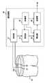
- FIG. 1shows a configuration example of a monitoring system 10 according to this embodiment.
- the monitoring system 10monitors a user's abnormal operation etc. based on the detection signal of the sensor provided in the clothes worn by the user.
- the monitoring system 10includes a clothing 20, a measurement device 30, an acquisition unit 40, a storage unit 50, a detection unit 60, and a notification unit 70.
- the clothing 20is worn by the user and provided with a sensor.
- the clothing 20is, for example, underwear, pajamas, hospital clothes, loungewear, or the like.
- the sensors provided on the clothes 20will be described later.
- the measuring device 30measures the state of the user wearing the clothing 20 based on the detection result of the sensor.
- the measurement device 30measures, for example, a user's motion, respiration, heartbeat, and other conditions.
- the measuring device 30may be attached to the clothing 20 of the user, or instead of this, may be provided separately from the clothing 20.
- the clothing 20 and the measuring device 30are connected, for example, by wire or wirelessly. In the monitoring system 10, for example, such a set of the clothing 20 and the measuring device 30 is provided for each user.
- the measurement device 30transmits the measurement result to the server 80 via the network 12, for example.
- the network 12is, for example, the Internet, but it may be a local area network instead.
- the server 80includes an acquisition unit 40, a storage unit 50, a detection unit 60, and a notification unit 70.
- the acquisition unit 40is connected to each of the plurality of measurement devices 30 and acquires the states of the plurality of users who wear the plurality of clothes 20.
- the acquisition unit 40respectively acquires the measurement result of the measurement device 30 indicating the state of the user.
- the acquisition unit 40may be connected to the plurality of measuring devices 30 via the network 12 or may be directly connected to the plurality of measuring devices 30.
- the storage unit 50stores the acquired measurement results of the plurality of measuring devices 30. Further, the storage unit 50 may store intermediate data generated (or used) by the monitoring system 10 in the process of operation, a calculation result, a threshold, a parameter, and the like. In addition, the storage unit 50 may supply the stored data to the request source in response to a request from each unit in the monitoring system 10.
- the detection unit 60detects an abnormal state among a plurality of user states.
- the detection unit 60detects, for example, a user who is apnea among a plurality of users. In this case, the detection unit 60 may detect the duration of the apnea of the user and the like. Further, the detection unit 60 detects, for example, a user whose heartbeat is less than a threshold value among a plurality of users. In this case, the detection unit 60 may detect the duration of the state in which the heartbeat of the user is less than the threshold value and the like.
- the notification unit 70notifies the outside that the abnormal unit is detected in response to the detection unit 60 detecting the abnormal user.
- the notification unit 70displays, for example, to the operator or the like of the monitoring system 10 that the abnormality is detected on the display unit or the like.
- the notification unit 70may notify the fact that the abnormality is detected by emitting a sound or the like.
- the notification unit 70may notify the external server or the like that an abnormality has been detected via the network 12.
- the monitoring system 10measures the state of the user based on the detection result of the sensor provided on the clothing 20 of the user, so that a large-scale measuring device using a bed or the like is used. Does not need For example, it can be easily applied to a plurality of users who are hospitalized in a relatively large hospital. Moreover, since the monitoring system 10 can monitor a plurality of users using the network 12 or the like, the monitoring system 10 can be configured irrespective of a specific building or area. The monitoring system 10 can monitor the states of a plurality of users including, for example, users who are receiving medical treatment at home. The clothing 20 and the measuring device 30 used by the monitoring system 10 will be described below.
- FIG. 2shows a configuration example of the clothing 20 and the measuring device 30 according to the present embodiment.
- the clothing 20is provided with a sensor element 100 as a sensor that detects the state of the user.
- the sensor element 100is provided so as to expand and contract according to the movement of the user's body.
- the sensor element 100is, for example, an element whose impedance changes according to the movement of the user's body.
- FIG. 2shows an example in which the sensor element 100 is provided in close contact with a position that surrounds the abdominal circumference of the user, and the impedance of the sensor element 100 changes according to the displacement of the abdominal circumference of the user.
- the inductance of the sensor element 100 changes according to the movement of the user's bodywill be described. Such a sensor element 100 will be described later.
- the clothing 20has a plurality of connecting portions 22 connected to the measuring device 30.
- Each of the connecting portions 22is electrically connected to the sensor element 100.
- the plurality of connecting portions 22function as input/output terminals of the sensor element 100.
- one or a plurality of connecting portions 22 among the plurality of connecting portions 22are a part of buttons provided on the clothing 20.
- FIG. 2shows an example in which the connecting portions 22 are provided at both ends of the sensor element 100.
- the buttonis, for example, a metal fastener such as a snap button.
- the snap buttonis composed of a set of a detachable concave button and a convex button, and it is desirable that either the concave button or the convex button is sewn to the clothing 20.
- the plurality of connecting portions 22can be easily attached to the clothing 20.
- the usercan wear the clothing 20 provided with the connecting portion 22 without any discomfort.
- the cable that electrically connects the clothing 20 and the measuring device 30can be used as a terminal for connecting either the concave button or the convex button to the clothing 20.
- the measuring device 30includes a measuring unit 32, a storage unit 34, a specifying unit 36, a transmitting unit 38, and a control unit 39.
- the measurement unit 32measures the inductance between two different connection units 22 of the plurality of connection units 22 of the clothing 20.
- FIG. 2shows an example in which the measuring section 32 measures the inductance between the two connecting sections 22 provided at both ends of the sensor element 100.
- the measuring unit 32may measure the inductance by a known measuring method, and detailed description thereof will be omitted here.
- the measuring unit 32supplies an alternating current signal having a predetermined amplitude voltage to the sensor element 100, and measures the inductance based on the measurement result of the alternating current flowing through the sensor element 100. It is desirable that the measurement unit 32 continuously measure the inductance to measure the change in the inductance. In this case, the measuring unit 32 may measure the inductance at every predetermined time, or instead, may measure the inductance at a substantially constant time interval.
- the storage unit 34stores the value of the inductance measured by the measuring unit 32. Further, the storage unit 34 may store intermediate data generated (or used) by the measuring device 30 in the process of operation, a calculation result, a threshold, a parameter, and the like. In addition, the storage unit 34 may supply the stored data to the request source in response to a request from each unit in the monitoring system 10.
- the identifying unit 36identifies the state of the user wearing the clothing 20 based on the measurement result of the inductance of the measuring unit 32.
- the identification unit 36identifies the state of the user, for example, according to the temporal variation of the inductance.
- the identifying unit 36identifies that the user is in a moving state such as turning over when the variation of the inductance has no periodicity and temporarily varies by a threshold value or more. Further, the specifying unit 36 may specify that the user is in an apnea state when the periodic fluctuation range of the inductance is less than the threshold value.
- the identifying unit 36determines that the respiration rate of the user is the reciprocal of the cycle. May be specified.
- the specifying unit 36determines that the heart rate of the user is concerned when the temporal fluctuation of the inductance fluctuates in a substantially constant cycle and the fluctuation range of the amplitude value is within a predetermined upper limit value and lower limit value. You may specify that it is the reciprocal of a period. Instead of this or in addition to this, the identifying unit 36 compares the measured change pattern of the inductance with the change pattern of the inductance that is stored in the storage unit 34 in the past and that changes with the breathing of the user. , The state of the user may be specified.
- the transmitting unit 38transmits the result specified by the specifying unit 36 to the acquisition unit 40.
- the transmission unit 38includes a transmission/reception circuit such as an antenna, and wirelessly transmits the identification result to the acquisition unit 40.
- the control unit 39controls the operations of the measuring unit 32, the storage unit 34, the specifying unit 36, and the transmitting unit 38.
- the control unit 39for example, the timing at which the measuring unit 32 measures the inductance, the timing at which the storage unit 34 stores the measurement result, the timing at which the specifying unit 36 acquires the measurement result and specifies the user's state, and the transmitting unit 38 It controls the timing of transmitting the specific result.
- the control unit 39controls each unit so that the inductance is measured at a predetermined time or time interval and the specific result is transmitted to the monitoring system 10.
- the control unit 39is, for example, a CPU (Central Processing Unit).
- the measuring device 30it is desirable that the measuring device 30 according to the present embodiment described above be formed by an integrated circuit or the like. Further, it is more preferable that the measuring device 30 is configured as a mobile portable device having a battery or the like. Accordingly, the measuring device 30 can be easily held in the pocket, belt, bag or the like of the user who wears the clothing 20. Further, the measuring device 30 may be configured as a part of a terminal carried by the user.
- the measuring device 30 described abovemeasures the state of the user based on the change in the inductance of the sensor element 100 provided on the clothing 20. The sensor element 100 whose inductance changes according to the state of the user will be described below.
- FIG. 3shows a configuration example of the sensor element 100 according to this embodiment.
- FIG. 3shows an example in which the sensor element 100 functions as a rubber string.
- the sensor element 100includes a base 110 and a sensor material 120. It should be noted that the sensor element 100 shown in FIG. 3 shows an example further including the connecting portion 22.
- the base 110is formed in a string shape or a band shape using a thread that can expand and contract in the longitudinal direction.
- the base 110is, for example, a band, a string, a cloth, or the like, which is formed of an elastic material. Further, the base 110 may be partially formed of a material having elasticity.
- FIG. 3shows an example in which the base 110 is a band-shaped rubber cord and expands and contracts in the X direction.
- the sensor material 120is formed so as to be stretchable in the longitudinal direction.
- the sensor material 120is bonded to the base 110 so that the base 110 can expand and contract in a direction in which the sensor material 120 can expand and contract.
- the sensor material 120may be woven into the base 110, for example, or alternatively, may be sewn to the base 110.
- the sensor material 120may be fixed to the base 110 with an adhesive or the like. Further, the sensor material 120 may be fixed by being sewn to the base body 110 together with the connecting portion 22. As a result, the sensor material 120 expands and contracts in the longitudinal direction, for example, when the base 110 expands and contracts in the longitudinal direction.
- the sensor material 120has an inductance component whose inductance value changes by expanding and contracting in the longitudinal direction. That is, the sensor material 120 is bonded to the base 110 such that the base 110 expands and contracts in the X direction to change the value of the inductance of the sensor material 120.
- FIG. 3shows an example in which two connecting portions 22 are provided on the base 110 and are electrically connected to both ends of the sensor material 120.
- the measuring device 30can measure the inductance of the sensor material 120 between the two connecting portions 22. Such a sensor material 120 will be described next.
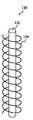
- FIG. 4shows a configuration example of the sensor material 120 according to this embodiment.
- the sensor material 120includes an insulating material 122 and a conductive fiber 124.
- the insulating material 122is stretchable in the longitudinal direction.
- the insulating material 122is formed of a material having elasticity.
- the insulating material 122is made of, for example, rubber or polymer.
- the insulating material 122may also include a material having a high dielectric constant.
- the insulating material 122is formed in, for example, a thread shape that extends in the longitudinal direction.
- the conductive fiber 124is made of a conductive material. Further, the conductive fiber 124 may be formed by attaching a conductive material to a fibrous material. The conductive fiber 124 may be, for example, a conductive film or the like, and instead of this, it may be formed by attaching conductive ink or the like to thread-shaped rubber, polymer or the like. The conductive fiber 124 is wound around the insulating material 122 in a coil shape.
- the above sensor material 120will have an inductance component according to the number of windings, the diameter, the length of the conductive fiber 124, the dielectric constant of the insulating material 122, and the like.
- the value of the inductanceincreases or decreases as the conductive fiber 124 expands and contracts in the longitudinal direction.
- the connecting portion 22is electrically connected to at least two portions of the conductive fiber 124. For example, when the two connecting portions 22 are connected to the conductive fiber 124, the measuring unit 32 can measure the inductance value of the conductive fiber 124 connected between the two connecting portions 22.
- the conductive fibers 124be fixed to a plurality of different portions of the insulating material 122.
- the insulating material 122 and the conductive fibers 124are adhesive at a first position and a position separated from the first position by the length of the conductive fibers 124 in a state where the conductive fibers 124 are not stretched. It is fixed by etc.
- the conductive fiber 124expands and contracts integrally with the insulating material 122. That is, the sensor material 120 functions as a sensor whose inductance value changes according to the expansion and contraction of the sensor material 120 in the longitudinal direction.
- the conductive fiber 124expands and contracts integrally with the base 110. That is, the sensor material 120 functions as a sensor that detects the length of the base 110 in the longitudinal direction.
- the sensor material 120may be bonded to the base 110 so that the conductive fibers 124 are fixed to different portions of the base 110. Even in this case, since the conductive fiber 124 expands and contracts integrally with the base 110, the sensor material 120 functions as a sensor that detects the length of the base 110 in the longitudinal direction.
- the sensor element 100can detect the displacement of the body of the user wearing the clothing 20.
- the sensor element 100as a rubber cord of the clothing 20 such as a shirt, underwear, or pants
- the sensor element 100can be arranged so as to surround the user's neck, chest, abdomen, or waist.
- the sensor element 100expands and contracts in the longitudinal direction according to the displacement of the user's body caused by the user's breathing, heartbeat, and the like, and changes the inductance according to the user's state. Therefore, the measuring device 30 can measure the state of the user by measuring the inductance of the sensor element 100.
- the sensor material 120operates as the sensor element 100 used as a part of the clothing 20 by being bonded to the rubber cord or the stretchable cloth or the like. As described above with reference to FIG. 4, since the sensor material 120 is formed in a thread shape, it is easy to form the sensor element 100, and it is easy to attach the sensor element 100 to the clothing 20 or replace it. is there.
- the sensor element 100can be fixed so as to surround the user's body as a stretchable elastic cord, the displacement of the sensor element 100 is unlikely to occur even when the user moves or rolls over. Further, even if the sensor element 100 is misaligned, the sensor element 100 is entrapped while being fixed so as to surround the user's body, so that the detection sensitivity can be prevented from being reduced. Further, since the measuring device 30 detects the periodic fluctuation of the inductance, the noise component due to the non-periodical movement of the user can be easily removed. Therefore, the measuring device 30 can easily detect a person's movement, respiration, heartbeat, and the like. Thereby, the cost can be reduced, and the simple and highly accurate monitoring system 10 can be realized.
- the example in which the sensor material 120 according to the present embodiment is provided on the clothing 20 by being combined with the base 110has been described above, but the present invention is not limited to this.
- the sensor material 120may be provided on the clothing 20.
- the clothing 20is formed of a stretchable cloth or the like at least in part, the sensor material 120 may be bonded to the stretchable cloth. In this case, it is desirable that the cloth can stretch in the direction in which the sensor material 120 can stretch.
- the sensor material 120may be bonded to the elastic cord.
- the clothing 20is formed of a cloth such as tights, spats, rash guard, abdomen, wristband, etc. that can be stretched in close contact with the user's body, the sensor material 120 is bonded to the cloth. It may have been done.
- the sensor material 120 or the sensor element 100may be arranged on any part of the clothing 20 as long as the displacement of the user wearing the clothing 20 can be detected.
- the sensor element 100may be at least a part of a belt such as a gown.
- the sensor element 100may be arranged on the chest, neck, arm, wrist or the like.
- the sensor element 100may be provided in a portion other than the clothing 20 as long as the displacement of the user can be detected.
- the sensor element 100may be at least a part of a rubber band of a hat.
- the sensor element 100may be a part of a belt, a suspender or the like.
- the measuring device 30measures the inductance between two different portions of the conductive fiber 124.
- the sensor material 120is longer, and it is more preferable that the sensor material 120 is provided on the clothing 20 to the extent that the sensor material 120 surrounds the circumference of the user.
- the measuring device 30may measure the inductance of a plurality of different portions of the conductive fiber 124. Such a measuring device 30 will be described next.
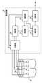
- FIG. 5shows a modification of the clothing 20 and the measuring device 30 according to the present embodiment.
- the clothing 20 of the modified examplehas a plurality of connection portions 22 electrically connected to each of the three or more portions of the conductive fiber 124.
- the plurality of connecting portions 22are respectively connected to a plurality of portions that are separated by a predetermined distance in the longitudinal direction of the conductive fiber 124, for example.
- FIG. 5shows an example in which a plurality of connecting portions 22 are connected to a plurality of portions that are equally spaced in the longitudinal direction of the conductive fiber 124.
- portions of the conductive fiber 124are shown as P 1 to P 4 .
- the measurement device 30 of the modificationfurther includes a switching unit 31 that switches electrical connection between the plurality of connection units 22 and the measurement unit 32.
- the switching unit 31has a plurality of switches.
- the control unit 39supplies the control signal for switching the plurality of switches of the switching unit 31 to the switching unit 31, and controls the switching unit 31 so that the measuring unit 32 can measure the inductance of the plurality of different portions of the conductive fiber 124. To do.
- the control unit 39controls the switching unit 31 to cause the measuring unit 32 to measure the inductance between the two adjacent connecting units 22, for example.
- control unit 39electrically connects, for example, the measuring unit 32 and the connecting unit 22 connected to P 1 and P 2 of the conductive fiber 124, and the measuring unit 32 and the conductive unit 124 are electrically connected.
- the switching unit 31is controlled so as to electrically disconnect between the connecting portion 22 connected to P 3 and P 4 of the sex fiber 124. Accordingly, the measuring unit 32 can measure the inductance between P 1 and P 2 of the conductive fiber 124.
- control unit 39then electrically connects the measuring unit 32 and the connecting unit 22 connected to P 2 and P 3 of the conductive fiber 124, and the measuring unit 32 and the conductive fiber 124.
- the switching unit 31is controlled so as to electrically disconnect between the connection unit 22 connected to P 1 and P 4 . Accordingly, the measuring unit 32 can measure the inductance between P 2 and P 3 of the conductive fiber 124.
- control unit 39may control the switching unit 31 so that the measuring unit 32 measures the inductance between P 3 and P 4 .
- the measuring device 30 of the modified examplecan measure the inductance of a plurality of different portions of the conductive fiber 124 to measure the user's state in more detail. For example, the measurement device 30 identifies the state of the user's heartbeat based on the measurement result of the portion of the conductive fiber 124 closer to the user's heart, and based on the measurement result of the portion closer to the user's lungs, the breathing of the user. The state of may be specified.
- the measuring apparatus 30determines the displacement on the right side of the user's abdomen from the change in the inductance between P 1 and P 2 , and the center of the user's abdomen from the change in the inductance between P 2 and P 3. Of the user's abdomen can be measured from the change in inductance between P 3 and P 4 , respectively. Thereby, the measuring device 30 can specify the movement state of the user, such as walking or turning over, from the difference between the displacements of the left and right abdomen of the user. Further, the measurement device 30 may identify the breathing and/or heartbeat state of the user from the difference between the displacement of each of the left and right abdomen of the user and the displacement of the center of the abdomen.
- the measurement device 30 of the present modificationhas described the example of measuring the inductance of a plurality of different portions of the single conductive fiber 124, but the measurement device 30 is not limited to this.
- the measuring device 30may measure the inductance of the plurality of conductive fibers 124.
- the clothing 20is provided with, for example, a plurality of sensor elements 100.
- the measuring device 30may measure the inductance of a plurality of different portions of each conductive fiber 124. Also in this case, the control unit 39 controls the switching unit 31 so that the measuring unit 32 can measure the portion of the conductive fiber 124 to be measured. Further, the measuring device 30 may include a plurality of measuring units 32 and may perform the inductance measurement in parallel.
- the measurement device 30has described the example of measuring the inductance of the conductive fiber 124.
- the measuring apparatus 30may measure the inductance of the conductive fiber 124 while comparing it with the inductance of the reference portion provided on the conductive fiber 124.
- the conductive fiber 124has a fixing region in which at least a part of the conductive fiber 124 is fixed so as not to expand and contract as the insulating material 122 expands and contracts. That is, the fixed portion of the conductive fiber 124 is a portion that is fixed so as to maintain a constant length in the longitudinal direction regardless of the state of the user.
- the fixed portion of the conductive fiber 124may be sewn to the clothing 20 or the base 110, or instead of this, may be fixed with an adhesive or the like.
- the clothing 20further has a plurality of connecting portions 22 electrically connected to each of two or more portions having different fixing regions.
- the region between P 1 and P 2 of the conductive fiber 124is the fixed region.
- the fixing region between P 1 and P 2is not connected to the insulating material 122, but is fixed to the clothing 20 or the base 110.
- the garment 20also has two connecting portions 22 that are electrically connected to P 1 and P 2 in the fixed region of the conductive fiber 124.
- the measuring unit 32can calculate the value of the inductance of the portion other than the fixed region of the conductive fiber 124 using the inductance between the two different connection units 22 provided in the fixed region as the reference value.
- the measurement unit 32can calculate the amount of increase or decrease of the inductance between P 2 and P 3 and between P 3 and P 4 , as compared with the inductance between P 1 and P 2 , for example.
- the measurement unit 32can measure the change in the absolute value of the inductance by measuring the value of the inductance in the fixed area in advance. Further, since the length of the fixed region of the conductive fiber 124 changes due to environmental changes such as temperature change, the measuring unit 32 cancels the influence of the environmental change by calculating the inductance in comparison with the fixed region. it can.
- the measuring device 30can accurately measure the inductance of each part of the conductive fiber 124.
- the fixing regionis a part of the conductive fiber 124 has been described, but the present invention is not limited to this.
- the fixed regionsmay be provided separately in the clothing 20 as long as they can be calculated as the reference value of the inductance. Further, it may be provided inside the measuring device 30.
- the measurement device 30is an example in which the state of the user is measured by using the sensor element 100 that is provided on the clothing 20 worn by the user and whose inductance changes according to the state of the user. Although described, the present invention is not limited to this.
- the measuring device 30may further use a sensor or the like whose capacitance and/or resistance changes according to the state of the user.
- the clothing 20includes an acceleration sensor for detecting acceleration when the user wearing the clothing 20 moves, and an acceleration sensor for detecting angular velocity and/or angular acceleration when the user wearing the clothing 20 moves.
- At least one of the gyro sensorsis further provided.
- the measuring device 30can measure changes in the posture of the user such as movement, standing up, sitting, and turning over based on the detection signals of the acceleration sensor and/or the gyro sensor. Therefore, the measurement device 30 can accurately measure the user's breathing, heartbeat, and the like by excluding the noise component due to such movement of the user.
- At least a part of the monitoring system 10 according to the present embodiment described aboveis, for example, a computer or the like.
- the computerfunctions as at least a part of the measurement device 30, the acquisition unit 40, the storage unit 50, the detection unit 60, and the notification unit 70 according to the present embodiment by executing a program or the like, for example.
- the computerincludes a processor such as a CPU, and executes a program stored in the storage unit 34 and/or the storage unit 50 to thereby obtain the measurement device 30, the acquisition unit 40, the storage unit 50, the detection unit 60, and the notification unit 70. Function as at least part of the.
- the computermay further include a GPU (Graphics Processing Unit) and the like.
- the present inventionhas been described above using the embodiments, the technical scope of the present invention is not limited to the scope described in the above embodiments, and various modifications and changes are possible within the scope of the gist thereof. is there.
- the specific embodiment of device distribution/integrationis not limited to the above embodiment, and all or part of the device may be functionally or physically distributed/integrated in arbitrary units.
- You can Further, a new embodiment that occurs due to an arbitrary combination of a plurality of embodimentsis also included in the embodiment of the present invention. The effect of the new embodiment produced by the combination also has the effect of the original embodiment.
- monitoring system10
- network20
- clothing22
- connection unit30
- measuring device31
- switching unit32
- measuring unit34
- storage unit36
- specifying unit38
- control unit40
- acquisition unit50
- storage unit60
- detection unit70
- notification unit80
- server100
- sensor element110
- Sensor Material122
- Insulating Material124 Conductive Fiber
Landscapes
- Health & Medical Sciences (AREA)
- Life Sciences & Earth Sciences (AREA)
- Engineering & Computer Science (AREA)
- Physics & Mathematics (AREA)
- General Health & Medical Sciences (AREA)
- Public Health (AREA)
- Animal Behavior & Ethology (AREA)
- Surgery (AREA)
- Veterinary Medicine (AREA)
- Biophysics (AREA)
- Pathology (AREA)
- Biomedical Technology (AREA)
- Heart & Thoracic Surgery (AREA)
- Medical Informatics (AREA)
- Molecular Biology (AREA)
- Physiology (AREA)
- Oral & Maxillofacial Surgery (AREA)
- Textile Engineering (AREA)
- Dentistry (AREA)
- General Physics & Mathematics (AREA)
- Cardiology (AREA)
- Physical Education & Sports Medicine (AREA)
- Mechanical Engineering (AREA)
- Pulmonology (AREA)
- Measurement Of The Respiration, Hearing Ability, Form, And Blood Characteristics Of Living Organisms (AREA)
- Measuring Pulse, Heart Rate, Blood Pressure Or Blood Flow (AREA)
- Yarns And Mechanical Finishing Of Yarns Or Ropes (AREA)
- Testing Or Calibration Of Command Recording Devices (AREA)
- Professional, Industrial, Or Sporting Protective Garments (AREA)
- Measuring And Recording Apparatus For Diagnosis (AREA)
Abstract
Description
Translated fromJapanese本発明は、センサ用材料、センサ素子、被服、測定装置、監視システム、およびプログラムに関する。The present invention relates to a sensor material, a sensor element, clothing, a measuring device, a monitoring system, and a program.
従来、人の動き、呼吸、心拍等を容易に検出する測定装置が望まれていた。特に、無呼吸症候群か否かを判定するための睡眠時の呼吸動作、病院等における患者の突然死、乳幼児のうつ伏せ死等を測定および監視できるシステムが望まれていた。このようなシステムとして、例えば、センサが設けられたベッド等を用いて人の呼吸動作等を検出するシステム、レーザ照射および撮像装置等で人の動きを検知するシステム等が知られていた。Conventionally, there has been a demand for a measuring device that easily detects human movement, respiration, heartbeat, and the like. In particular, there has been a demand for a system capable of measuring and monitoring respiratory motions during sleep for determining whether or not an apnea syndrome, sudden death of a patient in a hospital or the like, prone death of an infant or the like. As such a system, for example, a system for detecting a person's breathing motion using a bed or the like provided with a sensor, a system for detecting a person's movement with a laser irradiation and an imaging device, and the like have been known.
しかしながら、複数のユーザの状態をセンサ付きベッドで監視する場合、監視すべきユーザの人数に応じて複数のセンサ付きベッドを用意しなければならず、このような大掛かりで高価なシステムを容易に導入することは困難であった。また、光学的にユーザを監視する場合、光学系の死角に入ると検出感度が低減してしまうことがあった。したがって、人の動き、呼吸、心拍等を高精度かつ容易に検出して監視するシステムを実現することは困難であった。However, when monitoring the states of multiple users on a bed with sensors, multiple beds with sensors must be prepared according to the number of users to be monitored, and such a large-scale and expensive system can be easily introduced. It was difficult to do. Further, in the case of optically monitoring the user, the detection sensitivity may be reduced when the user enters a blind spot of the optical system. Therefore, it has been difficult to realize a system for detecting and monitoring human motion, respiration, heartbeat, etc. with high precision and ease.
そこで、本発明はこれらの点に鑑みてなされたものであり、人の動き、呼吸、心拍等を容易に検出することを目的とする。Therefore, the present invention has been made in view of these points, and an object thereof is to easily detect human movement, respiration, heartbeat, and the like.
本発明の第1の態様においては、長手方向に伸縮可能な絶縁性材料と、導電性を有し、前記絶縁性材料にコイル状に巻き付けられている導電性繊維とを備える、センサ用材料を提供する。前記導電性繊維は、前記絶縁性材料の異なる複数の部分に固定されていてもよい。In a first aspect of the present invention, there is provided a sensor material, comprising an insulating material which can be expanded and contracted in a longitudinal direction, and a conductive fiber which has conductivity and is wound around the insulating material in a coil shape. provide. The conductive fibers may be fixed to a plurality of different parts of the insulating material.
本発明の第2の態様においては、第1の態様の前記センサ用材料と、長手方向に伸縮可能な糸を用いて紐状または帯状に形成されている基体とを備え、前記センサ用材料が伸縮可能な方向に前記基体が伸縮可能であるように、前記センサ用材料が前記基体に結合されている、センサ素子を提供する。In a second aspect of the present invention, the sensor material of the first aspect and a base body formed in a string shape or a band shape by using a thread that can expand and contract in the longitudinal direction are provided, and the sensor material is A sensor element is provided in which the sensor material is bonded to the substrate such that the substrate is stretchable in a stretchable direction.
本発明の第3の態様においては、第2の態様の前記センサ素子が設けられている、被服を提供する。前記被服は、少なくとも一部に伸縮性を有する布を用いて形成され、第1の態様の前記センサ用材料が、伸縮性を有する前記布に結合されており、前記センサ用材料が伸縮可能な方向に、前記布が伸縮可能でよい。According to a third aspect of the present invention, there is provided clothing including the sensor element according to the second aspect. The clothing is formed by using a stretchable cloth at least in part, the sensor material of the first aspect is bonded to the stretchable cloth, and the sensor material is stretchable. The cloth may be stretchable in any direction.
前記被服は、前記導電性繊維の少なくとも2つの部分と電気的にそれぞれ接続される接続部を更に備えてよい。1または複数の前記接続部は、前記被服に設けられたボタンの一部でよい。The clothing may further include connecting portions electrically connected to at least two portions of the conductive fiber. The one or more connecting portions may be a part of a button provided on the clothing.
本発明の第4の態様においては、第3の態様の前記被服の複数の前記接続部のうち、異なる2つの前記接続部の間のインダクタンスを測定する測定部と、前記インダクタンスの測定結果に基づき、前記被服を着用したユーザの状態を特定する特定部とを備える、測定装置を提供する。In a fourth aspect of the present invention, based on a measurement section that measures an inductance between two different connection sections among the plurality of connection sections of the clothing of the third aspect, and a measurement result of the inductance. And a specifying unit that specifies the state of the user wearing the clothes.
前記被服は、前記導電性繊維の3以上の部分のそれぞれに電気的に接続されている複数の前記接続部を有し、複数の前記接続部と前記測定部との間の電気的な接続を切り換える切換部と、隣り合う2つの前記接続部の間のインダクタンスをそれぞれ前記測定部に測定させるように前記切換部を制御する制御部とを更に備えてもよい。The clothing has a plurality of the connecting portions electrically connected to each of the three or more portions of the conductive fiber, and provides an electrical connection between the plurality of the connecting portions and the measuring portion. A switching unit that switches and a control unit that controls the switching unit to cause the measuring unit to respectively measure the inductance between the two adjacent connecting units may be further provided.
前記導電性繊維は、少なくとも一部が前記絶縁性材料の伸縮に伴って伸縮しないように固定された固定領域を有し、前記被服は、前記固定領域の異なる2以上の部分のそれぞれに電気的に接続されている複数の前記接続部を更に有し、前記測定部は、前記固定領域に設けられた異なる2つの前記接続部の間のインダクタンスを基準値として、前記導電性繊維の前記固定領域以外の部分のインダクタンスの値を算出してもよい。At least a part of the conductive fiber has a fixing region fixed so as not to expand and contract with the expansion and contraction of the insulating material, and the clothing is electrically connected to each of two or more different parts of the fixing region. Further comprising a plurality of the connecting portions connected to the measuring portion, the measuring portion is a fixed area of the conductive fiber, with the inductance between two different connecting portions provided in the fixed area as a reference value. You may calculate the value of the inductance of a part other than.
前記被服は、前記被服を着用した前記ユーザが移動した場合の加速度を検出するための加速度センサと、前記被服を着用した前記ユーザが移動した場合の角速度および/または角加速度を検出するためのジャイロセンサのうち、少なくとも一方を更に備えてもよい。The clothing includes an acceleration sensor for detecting an acceleration when the user wearing the clothing moves, and a gyro for detecting an angular velocity and/or an angular acceleration when the user wearing the clothing moves. At least one of the sensors may be further provided.
本発明の第5の態様においては、第3の態様の前記被服と、複数の前記被服のそれぞれに接続される複数の第4の態様の前記測定装置と、複数の前記測定装置にそれぞれ接続され、複数の前記被服をそれぞれ着用した複数のユーザの状態を取得する取得部と、複数の前記ユーザの状態のうち、異常な状態を検知する検知部とを備える、監視システムを提供する。In a fifth aspect of the present invention, the clothing of the third aspect, the plurality of measuring devices of the fourth aspect connected to each of the plurality of clothing, and the plurality of measuring devices respectively connected. Provided is a monitoring system, comprising: an acquisition unit that acquires the states of a plurality of users who wear the plurality of clothes, and a detection unit that detects an abnormal state among the states of the plurality of users.
本発明の第6の態様においては、コンピュータにより実行されると、前記コンピュータを第5の態様の前記監視システムの少なくとも一部として機能させる、プログラムを提供する。The sixth aspect of the present invention provides a program that, when executed by a computer, causes the computer to function as at least a part of the monitoring system of the fifth aspect.
本発明によれば、人の動き、呼吸、心拍等を容易に検出できるという効果を奏する。According to the present invention, it is possible to easily detect human movement, respiration, heartbeat, and the like.
<監視システム10の構成例>
図1は、本実施形態に係る監視システム10の構成例を示す。監視システム10は、ユーザが着用している被服に設けられたセンサの検出信号に基づき、ユーザの異常動作等を監視する。監視システム10は、被服20と、測定装置30と、取得部40と、記憶部50と、検知部60と、通知部70とを備える。<Example of Configuration of
FIG. 1 shows a configuration example of a
被服20は、ユーザが着用し、センサが設けられている。被服20は、例えば、下着、パジャマ、病衣、部屋着等である。被服20に設けられているセンサについては、後述する。The
測定装置30は、センサの検出結果に基づき、被服20を着用したユーザの状態を測定する。測定装置30は、例えば、ユーザの動作、呼吸、および心拍等の状態を測定する。測定装置30は、ユーザの被服20に装着されていてよく、これに代えて、被服20とは別個に設けられていてもよい。被服20および測定装置30は、例えば、有線または無線で接続されている。監視システム10において、例えば、このような被服20および測定装置30の組がユーザ毎に設けられている。測定装置30は、例えばネットワーク12を介して、測定した結果をサーバ80に送信する。なお、ネットワーク12は、例えばインターネットであるが、これに代えて、ローカルエリアネットワークでもよい。The
サーバ80は、取得部40と、記憶部50と、検知部60と、通知部70とを有する。
取得部40は、複数の測定装置30にそれぞれ接続され、複数の被服20をそれぞれ着用した複数のユーザの状態を取得する。取得部40は、ユーザの状態を示す測定装置30の測定結果をそれぞれ取得する。取得部40は、ネットワーク12を介して複数の測定装置30と接続されていてもよく、複数の測定装置30と直接接続されていてもよい。The
The
記憶部50は、取得した複数の測定装置30の測定結果を記憶する。また、記憶部50は、監視システム10が動作の過程で生成する(または利用する)中間データ、算出結果、閾値、およびパラメータ等をそれぞれ記憶してもよい。また、記憶部50は、監視システム10内の各部の要求に応じて、記憶したデータを要求元に供給してもよい。The
検知部60は、複数のユーザの状態のうち、異常な状態を検知する。検知部60は、例えば、複数のユーザのうち無呼吸となっている状態のユーザを検知する。この場合、検知部60は、当該ユーザが無呼吸となっている状態の継続時間等を検知してもよい。また、検知部60は、例えば、複数のユーザのうち心拍が閾値未満となっているユーザを検知する。この場合、検知部60は、当該ユーザの心拍が閾値未満となっている状態の継続時間等を検知してもよい。The
通知部70は、検知部60が異常な状態のユーザを検知したことに応じて、異常なユーザを検知したことを外部に通知する。通知部70は、例えば、監視システム10のオペレータ等に対して、異常が検知されたことを表示部等に表示する。通知部70は、音声等を発して異常を検知したことを通知してもよい。また、通知部70は、ネットワーク12を介して、外部のサーバ等に異常を検知したことを通知してもよい。The
以上のように、本実施形態に係る監視システム10は、ユーザの被服20に設けられたセンサの検出結果に基づいて、ユーザの状態を測定するので、ベッド等を用いた大規模な測定装置等を必要としない。例えば、比較的規模の大きい病院等に入院する複数のユーザに対しても、容易に適用することができる。また、監視システム10は、ネットワーク12等を用いて複数のユーザを監視することができるので、特定の建物および地域等とは無関係に構成することができる。監視システム10は、例えば、自宅療養中のユーザ等を含めた複数のユーザの状態を監視できる。このような監視システム10が用いる被服20および測定装置30について次に説明する。As described above, the
<被服20および測定装置30の構成例>
図2は、本実施形態に係る被服20および測定装置30の構成例を示す。被服20は、ユーザの状態を検出するセンサとして、センサ素子100が設けられている。センサ素子100は、ユーザの体の動きに応じて伸縮するように設けられている。センサ素子100は、例えば、ユーザの身体の動きに応じて、インピーダンスが変動する素子である。図2は、センサ素子100がユーザの腹囲を囲うような位置に密着するように設けられ、ユーザの腹囲の変位に応じてセンサ素子100のインピーダンスが変動する例を示す。なお、本実施例において、ユーザの身体の動きに応じて、センサ素子100のインダクタンスが変化する例を説明する。このようなセンサ素子100については、後述する。<Structure example of
FIG. 2 shows a configuration example of the
被服20は、測定装置30と接続される複数の接続部22を有する。接続部22のそれぞれは、センサ素子100と電気的に接続される。複数の接続部22は、センサ素子100の入出力端子として機能する。例えば、複数の接続部22のうち、1つのまたは複数の接続部22は、被服20に設けられたボタンの一部である。図2は、センサ素子100の両端に接続部22が設けられた例を示す。The
ボタンは、例えば、スナップボタン等の金属製の留め具である。この場合、スナップボタンは、脱着可能な凹部ボタンおよび凸部ボタンの組で構成されており、凹部ボタンおよび凸部ボタンのいずれか一方が被服20に縫い付けられていることが望ましい。これにより、被服20に複数の接続部22を容易に取り付けることができる。また、ユーザは、接続部22が設けられている被服20を違和感なく着用できる。また、被服20および測定装置30を電気的に接続するケーブルは、凹部ボタンおよび凸部ボタンのいずれか一方を、被服20と接続するための端子として用いることができる。The button is, for example, a metal fastener such as a snap button. In this case, the snap button is composed of a set of a detachable concave button and a convex button, and it is desirable that either the concave button or the convex button is sewn to the
測定装置30は、測定部32と、記憶部34と、特定部36と、送信部38と、制御部39とを備える。測定部32は、被服20の複数の接続部22のうち、異なる2つの接続部22の間のインダクタンスを測定する。図2は、測定部32がセンサ素子100の両端に設けられた2つの接続部22の間のインダクタンスを測定する例を示す。The measuring
測定部32は、既知の測定方法により、インダクタンスを測定してよく、ここでは詳細な説明を省略する。例えば、測定部32は、予め定められた振幅電圧の交流信号をセンサ素子100に供給し、センサ素子100に流れる交流電流の測定結果に基づき、インダクタンスを測定する。測定部32は、継続してインダクタンスの測定を実行して、インダクタンスの変化を測定することが望ましい。この場合、測定部32は、予め定められた時間毎にインダクタンスを測定してもよく、これに代えて、略一定の時間間隔でインダクタンスの測定を継続してもよい。The measuring
記憶部34は、測定部32が測定したインダクタンスの値を記憶する。また、記憶部34は、測定装置30が動作の過程で生成する(または利用する)中間データ、算出結果、閾値、およびパラメータ等をそれぞれ記憶してもよい。また、記憶部34は、監視システム10内の各部の要求に応じて、記憶したデータを要求元に供給してもよい。The
特定部36は、測定部32のインダクタンスの測定結果に基づき、被服20を着用したユーザの状態を特定する。特定部36は、例えば、インダクタンスの時間的な変動に応じて、ユーザの状態を特定する。特定部36は、例えば、インダクタンスの変動に周期性がなく、一時的に閾値以上変動する場合、ユーザの寝返り等の移動状態であることを特定する。また、特定部36は、インダクタンスの周期的な変動幅が閾値未満の場合に、ユーザが無呼吸状態であることを特定してもよい。また、特定部36は、インダクタンスが略一定の周期で変動し、当該インダクタンスの変動幅が予め定められた上限値および下限値の範囲内の場合に、ユーザの呼吸数が当該周期の逆数であることを特定してもよい。The identifying
また、特定部36は、インダクタンスの時間的な変動が略一定の周期で変動し、振幅値の変動幅が予め定められた上限値および下限値の範囲内の場合に、ユーザの心拍数が当該周期の逆数であることを特定してもよい。これに代えて、または、これに加えて、特定部36は、測定したインダクタンスの変化パターンと、記憶部34が過去に記憶したユーザの呼吸に伴って変化するインダクタンスの変化パターンとを比較して、ユーザの状態を特定してもよい。Further, the specifying
送信部38は、特定部36が特定した結果を取得部40に送信する。測定装置30および取得部40が無線で接続されている場合、送信部38は、アンテナ等の送受信回路が含まれており、取得部40へと特定結果を無線で送信する。The transmitting
制御部39は、測定部32、記憶部34、特定部36、および送信部38の動作を制御する。制御部39は、例えば、測定部32がインダクタンスを測定するタイミング、記憶部34が測定結果を記憶するタイミング、特定部36が測定結果を取得してユーザの状態を特定するタイミング、送信部38が特定結果を送信するタイミング等を制御する。制御部39は、一例として、予め定められた時刻または時間間隔でインダクタンスを測定し、監視システム10に特定結果を送信するように各部を制御する。制御部39は、一例として、CPU(Central Processing Unit)である。The
以上の本実施形態に係る測定装置30は、集積回路等で形成されていることが望ましい。また、測定装置30は、バッテリー等を搭載したモバイル型の携帯型装置として構成されていることがより望ましい。これにより、測定装置30は、被服20を着用するユーザのポケット、ベルト、バッグ等に容易に保持することができる。また、測定装置30は、ユーザが携帯する端末の一部として構成されていてもよい。以上の測定装置30は、被服20に設けられたセンサ素子100のインダクタンスの変化に基づき、ユーザの状態を測定する。このようなユーザの状態に応じてインダクタンスが変化するセンサ素子100について、次に説明する。It is desirable that the measuring
<センサ素子100の構成例>
図3は、本実施形態に係るセンサ素子100の構成例を示す。図3は、センサ素子100がゴム紐として機能する例を示す。センサ素子100は、基体110とセンサ用材料120とを備える。なお、図3に示すセンサ素子100は、接続部22を更に有する例を示す。<Configuration Example of
FIG. 3 shows a configuration example of the
基体110は、長手方向に伸縮可能な糸を用いて紐状または帯状に形成されている。基体110は、例えば、弾性を有する材料で形成されている、帯、紐、布等である。また、基体110は、一部が弾性を有する材料で形成されていてもよい。図3は、基体110が帯状のゴム紐であり、X方向に伸縮する例を示す。The
センサ用材料120は、長手方向に伸縮可能に形成されている。センサ用材料120は、当該センサ用材料120が伸縮可能な方向に基体110が伸縮可能であるように、基体110に結合されている。センサ用材料120は、例えば、基体110に織り込まれていてよく、これに代えて、基体110に縫い付けられてもよい。また、センサ用材料120は、基体110に接着剤等で固定されていてもよい。また、センサ用材料120は、接続部22と共に、基体110に縫い付けられることで固定されていてもよい。これにより、センサ用材料120は、例えば、基体110が長手方向に伸縮すると、当該基体110と同様に長手方向に伸縮する。The
このように、センサ用材料120は、長手方向に伸縮することにより、インダクタンスの値が変化するインダクタンス成分を有する。即ち、基体110がX方向に伸縮することにより、センサ用材料120のインダクタンスの値が変化するように、センサ用材料120が基体110に結合されている。As described above, the
また、センサ用材料120が接続部22と電気的に接続されるように、当該接続部22が基体110に設けられている。図3は、2つの接続部22が基体110に設けられ、センサ用材料120の両端と電気的にそれぞれ接続されている例を示す。この場合、2つの接続部22と測定装置30とを接続することにより、当該測定装置30は、2つの接続部22の間のセンサ用材料120のインダクタンスを測定可能となる。このようなセンサ用材料120について、次に説明する。Further, the connecting
<センサ用材料120の構成例>
図4は、本実施形態に係るセンサ用材料120の構成例を示す。センサ用材料120は、絶縁性材料122と、導電性繊維124とを有する。絶縁性材料122は、長手方向に伸縮可能である。絶縁性材料122は、弾性を有する材料で形成されている。絶縁性材料122は、例えば、ゴム、ポリマー等で形成されている。また、絶縁性材料122は、高誘電率の材料を含んでもよい。絶縁性材料122は、例えば、長手方向に延伸する糸状に形成されている。<Structural Example of
FIG. 4 shows a configuration example of the
導電性繊維124は、導電性を有する材料で形成されている。また、導電性繊維124は、繊維状の材料に導電性材料が付着されて形成されていてもよい。導電性繊維124は、例えば、導電性フィルム等でよく、これに代えて、糸状のゴム、ポリマー等に導電性インク等が付着されて形成されていてもよい。導電性繊維124は、絶縁性材料122にコイル状に巻き付けられている。The
以上のセンサ用材料120は、導電性繊維124の巻き数、直径、長さ、絶縁性材料122の誘電率等に応じたインダクタンス成分を有することになる。また、センサ用材料120は、導電性繊維124が長手方向に伸縮することにより、インダクタンスの値が増減する。なお、接続部22は、導電性繊維124の少なくとも2つの部分と電気的にそれぞれ接続される。例えば、2つの接続部22が導電性繊維124に接続された場合、当該2つの接続部22の間に接続された導電性繊維124のインダクタンスの値を、測定部32が測定可能となる。The
ここで、導電性繊維124は、絶縁性材料122の異なる複数の部分に固定されていることが望ましい。例えば、絶縁性材料122および導電性繊維124は、第1の位置と、導電性繊維124が伸縮していない状態で第1の位置から導電性繊維124の長さだけ離れた位置とに接着剤等で固定されている。これにより、導電性繊維124は、絶縁性材料122と一体となって伸縮する。即ち、センサ用材料120は、当該センサ用材料120の長手方向の伸縮に応じて、インダクタンスの値が変化するセンサとして機能する。このようなセンサ用材料120が基体110に結合されることで、導電性繊維124は、基体110と一体となって伸縮する。即ち、センサ用材料120は、基体110の長手方向の長さを検出するセンサとして機能する。Here, it is desirable that the
これに代えて、または、これに加えて、導電性繊維124が基体110の異なる複数の部分に固定されるように、当該センサ用材料120が基体110に結合されていてもよい。この場合においても、導電性繊維124は、基体110と一体となって伸縮するので、センサ用材料120は、基体110の長手方向の長さを検出するセンサとして機能する。Alternatively or additionally, the
以上のセンサ用材料120が結合されたセンサ素子100が被服20の一部として用いられることにより、当該センサ素子100は、被服20を着用したユーザの体の変位を検出可能となる。例えば、センサ素子100をシャツ、下着、パンツ等の被服20のゴム紐として用いることにより、当該センサ素子100を、ユーザの首、胸、腹、または腰の周囲を囲うように配置できる。これにより、センサ素子100は、ユーザの呼吸および心拍等に起因するユーザの体の変位に応じて長手方向に伸縮することになり、ユーザの状態に応じて、インダクタンスを変化させる。したがって、測定装置30は、センサ素子100のインダクタンスを測定することにより、ユーザの状態を測定することができる。By using the
以上のように、本実施形態に係るセンサ用材料120は、ゴム紐または伸縮性を有する布等に結合され、被服20の一部として用いられるセンサ素子100として動作する。このようなセンサ用材料120は、図4で説明したように、糸状に形成されているので、センサ素子100を形成することは容易であり、また、被服20への取り付け、交換等も容易である。As described above, the
また、センサ素子100は、伸縮するゴム紐としてユーザの体に囲うように固定できるので、ユーザの移動および寝返り等によっても配置のずれが生じにくい。また、センサ素子100の配置にずれが生じたとしても、ユーザの体を囲うように固定されたままずれるので、検出感度の低減を防止できる。また、測定装置30は、インダクタンスの周期的な変動を検出するので、非周期的なユーザの移動等による雑音成分を容易に除去できる。したがって、測定装置30は、人の動き、呼吸、心拍等を容易に検出することができる。これにより、コストを低減させ、簡便で高精度な監視システム10を実現できる。Further, since the
以上の本実施形態に係るセンサ用材料120は、基体110と結合されて被服20に設けられる例を説明したが、これに限定されることはない。センサ用材料120は、被服20に設けられてもよい。例えば、被服20が、少なくとも一部に伸縮性を有する布等を用いて形成されている場合、センサ用材料120は、伸縮性を有する当該布に結合されていてよい。この場合、センサ用材料120が伸縮可能な方向に、布が伸縮可能であることが望ましい。The example in which the
例えば、被服20に既にゴム紐が設けられている場合、当該ゴム紐にセンサ用材料120が結合されていてもよい。また、被服20が、タイツ、スパッツ、ラッシュガード、腹巻、リストバンド等のように、ユーザの体と密着して伸縮するような布で形成されている場合、当該布にセンサ用材料120が結合されていてもよい。For example, when the
このように、被服20を着用するユーザの変位を検出できれば、センサ用材料120またはセンサ素子100を、当該被服20のいずれの部分に配置してもよい。例えば、センサ素子100は、ガウン等のベルトの少なくとも一部であってもよい。また、センサ素子100は、胸部、首、腕、手首等に配置されてもよい。また、ユーザの変位を検出できれば、センサ素子100は、被服20以外の部分に設けられてもよい。例えば、センサ素子100は、帽子のゴム紐の少なくとも一部であってもよい。また、センサ素子100は、ベルト、サスペンダ等の一部であってもよい。In this way, the
以上の本実施形態に係る測定装置30は、導電性繊維124の異なる2つの部分の間のインダクタンスを測定する例を説明した。測定感度をより向上させる目的で、センサ用材料120はより長い方が望ましく、センサ用材料120がユーザの周囲を囲う程度まで被服20に設けられることがより望ましい。なお、測定装置30は、導電性繊維124の異なる複数の部分のインダクタンスを測定してもよい。このような測定装置30について、次に説明する。The above has described an example in which the measuring
<導電性繊維124の複数個所のインダクタンスを測定する例>
図5は、本実施形態に係る被服20および測定装置30の変形例を示す。変形例の被服20は、導電性繊維124の3以上の部分のそれぞれに電気的に接続されている複数の接続部22を有する。複数の接続部22は、例えば、導電性繊維124の長手方向において、予め定められた間隔で離間した複数の部分にそれぞれ接続される。図5は、複数の接続部22が、導電性繊維124の長手方向において、等間隔に離間した複数の部分のそれぞれ接続される例を示す。図5において、導電性繊維124の複数の部分を、P1からP4として示す。<Example of Measuring Inductance at Plural Places of
FIG. 5 shows a modification of the
変形例の測定装置30は、複数の接続部22と測定部32との間の電気的な接続を切り換える切換部31を更に備える。切換部31は、複数のスイッチを有する。制御部39は、切換部31の複数のスイッチを切り換える制御信号を切換部31に供給して、測定部32が導電性繊維124の異なる複数の部分のインダクタンスを測定できるように切換部31を制御する。制御部39は、例えば、隣り合う2つの接続部22の間のインダクタンスをそれぞれ測定部32に測定させるように切換部31を制御する。The
図5の例の場合、制御部39は、例えば、測定部32と導電性繊維124のP1およびP2に接続された接続部22との間を電気的に接続し、測定部32と導電性繊維124のP3およびP4に接続された接続部22との間を電気的に切断するように切換部31を制御する。これにより、測定部32は、導電性繊維124のP1およびP2の間のインダクタンスを測定できる。In the case of the example of FIG. 5, the
この場合、制御部39は、次に、測定部32と導電性繊維124のP2およびP3に接続された接続部22との間を電気的に接続し、測定部32と導電性繊維124のP1およびP4に接続された接続部22との間を電気的に切断するように切換部31を制御する。これにより、測定部32は、導電性繊維124のP2およびP3の間のインダクタンスを測定できる。同様に、制御部39は、P3およびP4の間のインダクタンスを測定部32に測定させるように、切換部31を制御してもよい。In this case, the
以上のように、変形例の測定装置30は、導電性繊維124の異なる複数の部分のインダクタンスを測定して、ユーザの状態をより詳細に測定することができる。例えば、測定装置30は、導電性繊維124のうち、ユーザの心臓により近い部分の測定結果に基づき、ユーザの心拍の状態を特定し、ユーザの肺により近い部分の測定結果に基づき、ユーザの呼吸の状態を特定してもよい。As described above, the measuring
図5の例の場合、測定装置30は、P1およびP2の間のインダクタンスの変化からユーザの腹部の右側の変位を、P2およびP3の間のインダクタンスの変化からユーザの腹部の中央の変位を、P3およびP4の間のインダクタンスの変化からユーザの腹部の左側の変位を、それぞれ測定できる。これにより、測定装置30は、例えば、ユーザの左右の腹部の変位の差から、ユーザの歩行、寝返り等の移動状態を特定できる。また、測定装置30は、ユーザの左右の腹部の変位のそれぞれと、腹部の中央の変位との差分から、ユーザの呼吸および/または心拍の状態を特定してもよい。In the case of the example in FIG. 5, the measuring
なお、本変形例の測定装置30は、1つの導電性繊維124の異なる複数の部分のインダクタンスを測定する例を説明したが、これに限定されることはない。測定装置30は、複数の導電性繊維124のインダクタンスを測定してもよい。この場合、被服20には、例えば、複数のセンサ素子100が設けられている。The
また、測定装置30は、被服20に複数の導電性繊維124が設けられる場合、それぞれの導電性繊維124の異なる複数の部分のインダクタンスを測定してもよい。この場合においても、制御部39は、測定部32が導電性繊維124の測定すべき部分を測定できるように、切換部31を制御する。また、測定装置30は、測定部32を複数備え、インダクタンスの測定を並列に実行してもよい。When the
<基準値を用いてインダクタンスを測定する例>
以上の本実施形態に係る測定装置30は、導電性繊維124のインダクタンスを測定する例を説明した。ここで、測定装置30は、導電性繊維124のインダクタンスを、当該導電性繊維124に設けられた基準部分のインダクタンスと比較しながら測定してもよい。この場合、導電性繊維124は、少なくとも一部が絶縁性材料122の伸縮に伴って伸縮しないように固定された固定領域を有する。即ち、導電性繊維124の固定部分は、ユーザの状態とは無関係に、一定の長手方向の長さを保持するように固定されている部分である。導電性繊維124の固定部分は、被服20または基体110に縫い付けられていてもよく、これに代えて、接着剤等で固定されてもよい。<Example of measuring inductance using a reference value>
The
そして、被服20は、固定領域の異なる2以上の部分のそれぞれに電気的に接続されている複数の接続部22を更に有する。図5の例において、例えば、導電性繊維124のP1およびP2の間の領域を固定領域とする。この場合、P1およびP2の間の固定領域は、絶縁性材料122には接続されず、被服20または基体110に固定される。また、被服20は、導電性繊維124の固定領域のP1およびP2に電気的に接続される2つの接続部22を有する。The
これにより、測定部32は、固定領域に設けられた異なる2つの接続部22の間のインダクタンスを基準値として、導電性繊維124の固定領域以外の部分のインダクタンスの値を算出できる。測定部32は、例えば、P1およびP2の間のインダクタンスと比較して、P2およびP3の間と、P3およびP4の間のインダクタンスの増加量または減少量を算出できる。Accordingly, the measuring
導電性繊維124の固定領域は一定の長さを保つので、当該固定領域のインダクタンスの値を予め測定することにより、測定部32は、インダクタンスの絶対値の変化を測定できる。また、導電性繊維124の固定領域の長さは、温度変化等の環境変動によって変化するので、測定部32は、固定領域と比較してインダクタンスを算出することにより、当該環境変動の影響をキャンセルできる。Since the fixed area of the
したがって、測定装置30は、導電性繊維124の各部のインダクタンスを精度よく測定することができる。なお、本実施形態において、固定領域が導電性繊維124の一部である例を説明したが、これに限定されることはない。固定領域は、インダクタンスの基準値として算出できれば、被服20に別個独立に設けられていてもよい。また、測定装置30の内部に設けられていてもよい。Therefore, the measuring
以上の本実施形態に係る測定装置30は、ユーザが着用している被服20に設けられ、当該ユーザの状態に応じてインダクタンスが変化するセンサ素子100を用いて、ユーザの状態を測定する例を説明したが、これに限定されることはない。測定装置30は、ユーザの状態に応じて、更に、容量および/または抵抗等が変化するセンサ等を更に用いてもよい。The
<被服20が他のセンサを有する例>
例えば、被服20は、当該被服20を着用したユーザが移動した場合の加速度を検出するための加速度センサと、被服20を着用したユーザが移動した場合の角速度および/または角加速度を検出するためのジャイロセンサのうち、少なくとも一方を更に備える。この場合、測定装置30は、加速度センサおよび/またはジャイロセンサの検出信号に基づき、ユーザの移動、立ち上がり、着座、寝返り等の姿勢の変化等を測定できる。したがって、測定装置30は、このようなユーザの移動等の動作による雑音成分を除外して、ユーザの呼吸および心拍等を精度よく測定することができる。<Example in which the
For example, the
以上の本実施形態に係る監視システム10の少なくとも一部は、一例として、コンピュータ等である。コンピュータは、例えば、プログラム等を実行することにより、本実施形態に係る測定装置30、取得部40、記憶部50、検知部60、および通知部70のうちの少なくとも一部として機能する。At least a part of the
コンピュータは、CPU等のプロセッサを備え、記憶部34および/または記憶部50に記憶されたプログラムを実行することによって、測定装置30、取得部40、記憶部50、検知部60、および通知部70の少なくとも一部として機能する。コンピュータは、GPU(Graphics Processing Unit)等を更に備えてもよい。The computer includes a processor such as a CPU, and executes a program stored in the
以上、本発明を実施の形態を用いて説明したが、本発明の技術的範囲は上記実施の形態に記載の範囲には限定されず、その要旨の範囲内で種々の変形及び変更が可能である。例えば、装置の分散・統合の具体的な実施の形態は、以上の実施の形態に限られず、その全部又は一部について、任意の単位で機能的又は物理的に分散・統合して構成することができる。また、複数の実施の形態の任意の組み合わせによって生じる新たな実施の形態も、本発明の実施の形態に含まれる。組み合わせによって生じる新たな実施の形態の効果は、もとの実施の形態の効果を合わせ持つ。Although the present invention has been described above using the embodiments, the technical scope of the present invention is not limited to the scope described in the above embodiments, and various modifications and changes are possible within the scope of the gist thereof. is there. For example, the specific embodiment of device distribution/integration is not limited to the above embodiment, and all or part of the device may be functionally or physically distributed/integrated in arbitrary units. You can Further, a new embodiment that occurs due to an arbitrary combination of a plurality of embodiments is also included in the embodiment of the present invention. The effect of the new embodiment produced by the combination also has the effect of the original embodiment.
10 監視システム
12 ネットワーク
20 被服
22 接続部
30 測定装置
31 切換部
32 測定部
34 記憶部
36 特定部
38 送信部
39 制御部
40 取得部
50 記憶部
60 検知部
70 通知部
80 サーバ
100 センサ素子
110 基体
120 センサ用材料
122 絶縁性材料
124 導電性繊維10
Claims (13)
Translated fromJapanese導電性を有し、前記絶縁性材料にコイル状に巻き付けられている導電性繊維と
を備える、センサ用材料。An insulating material that can expand and contract in the longitudinal direction,
A conductive material, which has conductivity and is wound around the insulating material in a coil shape.
請求項1に記載のセンサ用材料。The conductive fibers are fixed to a plurality of different portions of the insulating material,
The sensor material according to claim 1.
長手方向に伸縮可能な糸を用いて紐状または帯状に形成されている基体と
を備え、
前記センサ用材料が伸縮可能な方向に前記基体が伸縮可能であるように、前記センサ用材料が前記基体に結合されている、センサ素子。The sensor material according to claim 1 or 2,
And a base body formed in a string shape or a band shape using a thread that can expand and contract in the longitudinal direction,
A sensor element, wherein the sensor material is bonded to the base so that the base can expand and contract in a direction in which the sensor material can expand and contract.
請求項1または2に記載の前記センサ用材料が、伸縮性を有する前記布に結合されており、
前記センサ用材料が伸縮可能な方向に、前記布が伸縮可能である、被服。Formed using a stretchable fabric at least in part,
The sensor material according to claim 1 or 2 is bonded to the stretchable cloth,
A garment in which the cloth is stretchable in a direction in which the sensor material can stretch.
前記インダクタンスの測定結果に基づき、前記被服を着用したユーザの状態を特定する特定部と
を備える、測定装置。A measuring unit for measuring an inductance between two different connection units among the plurality of connection units of the clothing according to claim 6 or 7.
And a specifying unit that specifies the state of the user wearing the clothing based on the measurement result of the inductance.
複数の前記接続部と前記測定部との間の電気的な接続を切り換える切換部と、
隣り合う2つの前記接続部の間のインダクタンスをそれぞれ前記測定部に測定させるように前記切換部を制御する制御部と
を更に備える、請求項8に記載の測定装置。The clothing has a plurality of the connecting portions electrically connected to each of the three or more portions of the conductive fiber,
A switching unit that switches electrical connection between the plurality of connection units and the measurement unit,
The measurement device according to claim 8, further comprising: a control unit that controls the switching unit to cause the measurement unit to measure an inductance between two adjacent connection units.
前記被服は、前記固定領域の異なる2以上の部分のそれぞれに電気的に接続されている複数の前記接続部を更に有し、
前記測定部は、前記固定領域に設けられた異なる2つの前記接続部の間のインダクタンスを基準値として、前記導電性繊維の前記固定領域以外の部分のインダクタンスの値を算出する、
請求項9に記載の測定装置。The conductive fiber has a fixing region at least a part of which is fixed so as not to expand and contract with the expansion and contraction of the insulating material,
The clothing further includes a plurality of the connecting portions electrically connected to each of two or more different portions of the fixing region,
The measuring unit calculates the value of the inductance of the portion of the conductive fiber other than the fixed region, using the inductance between two different connection units provided in the fixed region as a reference value.
The measuring device according to claim 9.
複数の前記被服のそれぞれに接続される複数の請求項8から10のいずれか一項に記載の前記測定装置と、
複数の前記測定装置にそれぞれ接続され、複数の前記被服をそれぞれ着用した複数のユーザの状態を取得する取得部と、
複数の前記ユーザの状態のうち、異常な状態を検知する検知部と
を備える、監視システム。A plurality of the clothes according to claim 6 or 7,
A plurality of the measuring devices according to any one of claims 8 to 10 connected to each of a plurality of the clothes,
An acquisition unit that is connected to each of the plurality of measurement devices and acquires the states of a plurality of users who wear the plurality of clothes, respectively.
A monitoring system including a detection unit that detects an abnormal state among a plurality of states of the user.
A program that, when executed by a computer, causes the computer to function as at least part of the monitoring system of claim 12.
Priority Applications (3)
| Application Number | Priority Date | Filing Date | Title |
|---|---|---|---|
| PCT/JP2019/001101WO2020148829A1 (en) | 2019-01-16 | 2019-01-16 | Sensor material, sensor element, garment, measurement device, monitoring system, and program |
| JP2020566018AJP7240753B2 (en) | 2019-01-16 | 2019-01-16 | Clothing, measurement equipment, and monitoring systems |
| US17/376,347US20220000424A1 (en) | 2019-01-16 | 2021-07-15 | Garment, measurement apparatus and monitoring system |
Applications Claiming Priority (1)
| Application Number | Priority Date | Filing Date | Title |
|---|---|---|---|
| PCT/JP2019/001101WO2020148829A1 (en) | 2019-01-16 | 2019-01-16 | Sensor material, sensor element, garment, measurement device, monitoring system, and program |
Related Child Applications (1)
| Application Number | Title | Priority Date | Filing Date |
|---|---|---|---|
| US17/376,347ContinuationUS20220000424A1 (en) | 2019-01-16 | 2021-07-15 | Garment, measurement apparatus and monitoring system |
Publications (1)
| Publication Number | Publication Date |
|---|---|
| WO2020148829A1true WO2020148829A1 (en) | 2020-07-23 |
Family
ID=71613219
Family Applications (1)
| Application Number | Title | Priority Date | Filing Date |
|---|---|---|---|
| PCT/JP2019/001101CeasedWO2020148829A1 (en) | 2019-01-16 | 2019-01-16 | Sensor material, sensor element, garment, measurement device, monitoring system, and program |
Country Status (3)
| Country | Link |
|---|---|
| US (1) | US20220000424A1 (en) |
| JP (1) | JP7240753B2 (en) |
| WO (1) | WO2020148829A1 (en) |
Cited By (1)
| Publication number | Priority date | Publication date | Assignee | Title |
|---|---|---|---|---|
| JPWO2020148827A1 (en)* | 2019-01-16 | 2021-12-02 | Posh Wellness Laboratory株式会社 | Detection device, state identification device, and measurement method |
Families Citing this family (1)
| Publication number | Priority date | Publication date | Assignee | Title |
|---|---|---|---|---|
| US12053672B2 (en)* | 2021-11-29 | 2024-08-06 | Sword Health, S.A. | Sensing of stretching of straps of motion tracking system for enhanced usage of the system |
Citations (6)
| Publication number | Priority date | Publication date | Assignee | Title |
|---|---|---|---|---|
| JP2011089923A (en)* | 2009-10-23 | 2011-05-06 | Asahi Kasei Fibers Corp | Sensing member and sensor provided with the sensing member |
| JP2016150102A (en)* | 2015-02-17 | 2016-08-22 | 日本電信電話株式会社 | Sequential attitude identification device, autonomic nerve function information acquisition device, method, and program |
| JP2017110307A (en)* | 2015-12-14 | 2017-06-22 | グンゼ株式会社 | Clothing |
| JP2017519120A (en)* | 2014-05-29 | 2017-07-13 | ライク ア グローヴ リミテッド | Self measuring clothing |
| EP3366211A1 (en)* | 2017-02-27 | 2018-08-29 | Koninklijke Philips N.V. | Wearable device |
| JP2018141252A (en)* | 2017-02-28 | 2018-09-13 | 帝人フロンティア株式会社 | Clothing |
Family Cites Families (8)
| Publication number | Priority date | Publication date | Assignee | Title |
|---|---|---|---|---|
| AU2003279888A1 (en)* | 2002-06-28 | 2004-01-19 | North Carolina State University | Fabric and yarn structures for improving signal integrity in fabric based electrical circuits |
| US7135227B2 (en)* | 2003-04-25 | 2006-11-14 | Textronics, Inc. | Electrically conductive elastic composite yarn, methods for making the same, and articles incorporating the same |
| FR2858758B1 (en)* | 2003-08-14 | 2006-04-07 | Tam Telesante Sarl | MEDICAL MONITORING SYSTEM USING A CLOTHING |
| US20060218778A1 (en)* | 2005-04-04 | 2006-10-05 | Govindaraj Jawahar | Flexible conducting thread |
| JP5791132B1 (en)* | 2014-04-07 | 2015-10-07 | 学校法人北里研究所 | Detection device, detection system, detection method and program |
| EP3633089B1 (en)* | 2015-06-30 | 2021-04-21 | School Juridical Person The Kitasato Institute | Detection device and liquid type estimation method |
| CN108139197B (en)* | 2015-09-01 | 2020-11-17 | 霍尼韦尔安全产品美国股份有限公司 | System and method for monitoring respiration in biosensing garments |
| WO2018092886A1 (en)* | 2016-11-18 | 2018-05-24 | 三井化学株式会社 | Piezoelectric base material, sensor, actuator, biological information acquisition device, and piezoelectric fiber structure |
- 2019
- 2019-01-16JPJP2020566018Apatent/JP7240753B2/enactiveActive
- 2019-01-16WOPCT/JP2019/001101patent/WO2020148829A1/ennot_activeCeased
- 2021
- 2021-07-15USUS17/376,347patent/US20220000424A1/ennot_activeAbandoned
Patent Citations (6)
| Publication number | Priority date | Publication date | Assignee | Title |
|---|---|---|---|---|
| JP2011089923A (en)* | 2009-10-23 | 2011-05-06 | Asahi Kasei Fibers Corp | Sensing member and sensor provided with the sensing member |
| JP2017519120A (en)* | 2014-05-29 | 2017-07-13 | ライク ア グローヴ リミテッド | Self measuring clothing |
| JP2016150102A (en)* | 2015-02-17 | 2016-08-22 | 日本電信電話株式会社 | Sequential attitude identification device, autonomic nerve function information acquisition device, method, and program |
| JP2017110307A (en)* | 2015-12-14 | 2017-06-22 | グンゼ株式会社 | Clothing |
| EP3366211A1 (en)* | 2017-02-27 | 2018-08-29 | Koninklijke Philips N.V. | Wearable device |
| JP2018141252A (en)* | 2017-02-28 | 2018-09-13 | 帝人フロンティア株式会社 | Clothing |
Cited By (1)
| Publication number | Priority date | Publication date | Assignee | Title |
|---|---|---|---|---|
| JPWO2020148827A1 (en)* | 2019-01-16 | 2021-12-02 | Posh Wellness Laboratory株式会社 | Detection device, state identification device, and measurement method |
Also Published As
| Publication number | Publication date |
|---|---|
| JPWO2020148829A1 (en) | 2021-12-02 |
| US20220000424A1 (en) | 2022-01-06 |
| JP7240753B2 (en) | 2023-03-16 |
Similar Documents
| Publication | Publication Date | Title |
|---|---|---|
| JP6986667B2 (en) | Wearing device for detecting human body movement | |
| US20100286546A1 (en) | Garment for detecting respiratory movement | |
| JP2008513152A (en) | Improved sensor for inductive plethysmograph monitoring applications and apparel using it | |
| US11962652B2 (en) | Method for sensing of biometric data and use thereof for bidirectional communication with networked devices | |
| KR101912730B1 (en) | A garment-like device for monitoring a user's physiological parameters | |
| US20220000424A1 (en) | Garment, measurement apparatus and monitoring system | |
| US11478192B2 (en) | Apparatus for sensing comprising a flexible substrate | |
| US12433509B2 (en) | Elongation sensor and wearable article including the elongation sensor | |
| Balasubramaniyam et al. | Design and development of a IoT based flexible and wearable T-shirt for monitoring breathing rate | |
| GB2500000A (en) | Microwave monitoring using an electrically conductive textile | |
| TWM463109U (en) | Physiology detecting textile | |
| US12008429B2 (en) | Wearable assembly | |
| WO2023052752A1 (en) | System comprising article and electronics module | |
| WO2020148828A1 (en) | Seat belt and state identifying device | |
| US20250017530A1 (en) | Motion Recognition Clothing (Wearable Device for Measuring Full-Body Configuration and Motion) | |
| US20230263475A1 (en) | System Comprising an Electronics Module | |
| WO2022180390A1 (en) | Electronics module and assembly comprising electronics module and fabric article | |
| GB2597726A (en) | System comprising an electronics module | |
| GB2604111A (en) | Electronics module and assembly comprising electronics module and fabric article | |
| GB2596051A (en) | Wearable article and method | |
| PL227251B1 (en) | Textronic system to monitor patient's health condition |
Legal Events
| Date | Code | Title | Description |
|---|---|---|---|
| 121 | Ep: the epo has been informed by wipo that ep was designated in this application | Ref document number:19909964 Country of ref document:EP Kind code of ref document:A1 | |
| ENP | Entry into the national phase | Ref document number:2020566018 Country of ref document:JP Kind code of ref document:A | |
| NENP | Non-entry into the national phase | Ref country code:DE | |
| 122 | Ep: pct application non-entry in european phase | Ref document number:19909964 Country of ref document:EP Kind code of ref document:A1 |