WO2020144849A1 - Mobile object positioning device and mobile object management device - Google Patents
Mobile object positioning device and mobile object management deviceDownload PDFInfo
- Publication number
- WO2020144849A1 WO2020144849A1PCT/JP2019/000692JP2019000692WWO2020144849A1WO 2020144849 A1WO2020144849 A1WO 2020144849A1JP 2019000692 WJP2019000692 WJP 2019000692WWO 2020144849 A1WO2020144849 A1WO 2020144849A1
- Authority
- WO
- WIPO (PCT)
- Prior art keywords
- mobile
- self
- positioning device
- position information
- mobile body
- Prior art date
- Legal status (The legal status is an assumption and is not a legal conclusion. Google has not performed a legal analysis and makes no representation as to the accuracy of the status listed.)
- Ceased
Links
Images


Classifications
- G—PHYSICS
- G01—MEASURING; TESTING
- G01S—RADIO DIRECTION-FINDING; RADIO NAVIGATION; DETERMINING DISTANCE OR VELOCITY BY USE OF RADIO WAVES; LOCATING OR PRESENCE-DETECTING BY USE OF THE REFLECTION OR RERADIATION OF RADIO WAVES; ANALOGOUS ARRANGEMENTS USING OTHER WAVES
- G01S13/00—Systems using the reflection or reradiation of radio waves, e.g. radar systems; Analogous systems using reflection or reradiation of waves whose nature or wavelength is irrelevant or unspecified
- G01S13/74—Systems using reradiation of radio waves, e.g. secondary radar systems; Analogous systems
- G—PHYSICS
- G01—MEASURING; TESTING
- G01S—RADIO DIRECTION-FINDING; RADIO NAVIGATION; DETERMINING DISTANCE OR VELOCITY BY USE OF RADIO WAVES; LOCATING OR PRESENCE-DETECTING BY USE OF THE REFLECTION OR RERADIATION OF RADIO WAVES; ANALOGOUS ARRANGEMENTS USING OTHER WAVES
- G01S5/00—Position-fixing by co-ordinating two or more direction or position line determinations; Position-fixing by co-ordinating two or more distance determinations
- G01S5/02—Position-fixing by co-ordinating two or more direction or position line determinations; Position-fixing by co-ordinating two or more distance determinations using radio waves
- H—ELECTRICITY
- H04—ELECTRIC COMMUNICATION TECHNIQUE
- H04W—WIRELESS COMMUNICATION NETWORKS
- H04W64/00—Locating users or terminals or network equipment for network management purposes, e.g. mobility management
- G—PHYSICS
- G05—CONTROLLING; REGULATING
- G05D—SYSTEMS FOR CONTROLLING OR REGULATING NON-ELECTRIC VARIABLES
- G05D1/00—Control of position, course, altitude or attitude of land, water, air or space vehicles, e.g. using automatic pilots
- G05D1/02—Control of position or course in two dimensions
Definitions
- the present inventionrelates to a mobile positioning device and a mobile management device.
- Patent Document 1discloses a self-position correction device for a moving body. According to the self-position correcting device, the self-position of the moving body can be detected by searching the landmark of the image of the camera unit.
- An object of the present inventionis to provide a mobile body positioning device and a mobile body management device that can easily detect the self-position of a mobile body.
- a mobile body positioning deviceis provided in a mobile body, and a radio tag reading unit that wirelessly reads unique information of the radio tag from a radio tag provided in a building, and the mobile body positioning device is provided in the mobile body. And a self-position information calculation unit that calculates self-position information of the moving body based on the unique information read by the tag reading unit.
- the mobile management deviceincludes an information holding unit that holds the self-position information and the identification information transmitted by the mobile positioning device in association with each other.
- the mobile body positioning devicecalculates the self-position information of the mobile body based on the unique information read from the wireless tag. Therefore, the self-position of the moving body can be easily detected.
- FIG. 3is a configuration diagram of a mobile body system in the first embodiment.
- FIG. 6is a perspective view for explaining a first example of control of a moving body by the moving body system in the first embodiment.
- FIG. 6is a perspective view for explaining a first example of control of a moving body by the moving body system in the first embodiment.
- FIG. 6is a perspective view for explaining a second example of control of a moving body by the moving body system in the first embodiment.
- FIG. 6is a perspective view for explaining a second example of control of a moving body by the moving body system in the first embodiment.
- 5is a flowchart for explaining a first example of the operation of the mobile body positioning device of the mobile body system in the first embodiment.
- FIG. 5is a flowchart for explaining a second example of the operation of the mobile body positioning device of the mobile body system in the first embodiment.
- 9is a flowchart for explaining a third example of the operation of the mobile body positioning device of the mobile body system in the first embodiment.
- 9is a flowchart for explaining a fourth example of the operation of the mobile body positioning device of the mobile body system in the first embodiment.
- FIG. 3is a hardware configuration diagram of a mobile management device of the mobile system according to the first embodiment.
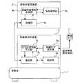
- FIG. 1is a configuration diagram of a mobile system according to the first embodiment.
- the mobile body 1is provided so as to be able to autonomously move inside a building.
- the wireless tag 2is provided on the building.
- the wireless tag 2is provided on the wall surface of a building or the like.
- the wireless tag 2is provided so as to be able to transmit a response radio wave when receiving the detection radio wave.
- the wireless tagis an IC (Integrated Circuit) tag equipped with an RFID (Radio Frequency Identification) system.
- the communication range of the radio wave detected by the wireless tag 2is about several meters in radius. Accordingly, when there is the wireless tag 2 that responds, it can be detected that the wireless tag 2 exists within the radius m.
- the mobile body positioning device 3is provided in the mobile body 1.
- the mobile body positioning device 3includes a wireless tag reading unit 3a, a self-position information calculation unit 3b, a communication unit 3c, and a control unit 3d.
- the wireless tag reading unit 3ais provided so as to be able to transmit detection radio waves.
- the wireless tag reading unit 3ais provided so as to read the unique information of the wireless tag 2 from the response radio wave of the wireless tag 2.
- the self-position information calculating unit 3bis provided so as to be able to calculate the self-position information of the moving body 1 based on the unique information read by the wireless tag reading unit 3a.
- the communication unit 3cis provided so that it can communicate with an external device.
- the control unit 3dis provided so as to allow the communication unit 3c to transmit the self-position information calculated by the self-position information calculation unit 3b and the identification information of the self to the external device.
- the mobile management device 4is provided in a building management room or the like.
- the mobile management device 4includes a communication unit 4a, an installation position information reference unit 4b, and an information holding unit 4c.
- the communication unit 4ais provided so as to be able to wirelessly communicate with the communication unit 3c of the mobile positioning device 3.
- the installation position information reference unit 4bis provided so as to be able to store information in which the unique information of the wireless tag 2 and the installation position information in the building are associated with each other.
- the information holding unit 4cis provided so as to hold the self-position transmitted by the communication unit 3c of the mobile positioning device 3 and the identification information in association with each other.
- FIGS. 2 and 3are perspective views for explaining a first example of control of a moving body by the moving body system according to the first embodiment.
- the mobile positioning device 3calculates self-position information based on the unique information from the wireless tag 2.
- the detection range of the wireless tag 2is set to the prohibited area. ..
- the mobile positioning device 3calculates the self-position information based on the unique information from the wireless tag 2, if the self-position information corresponds to the entry prohibited area, the mobile positioning device 3 determines that the entry prohibited area. The command corresponding to is transmitted to the mobile unit 1.
- FIGS. 4 and 5are perspective views for explaining a second example of control of a moving body by the moving body system in the first embodiment.
- the mobile body positioning device 3determines its own position information based on the unique information from the plurality of wireless tags 2. calculate.
- the mobile positioning device 3calculates the self-position information based on the unique information from the plurality of wireless tags 2, the self-position information corresponds to the prohibited area, and the unique information is read from the plurality of wireless tags.
- the mobile body positioning device 3transmits a command corresponding to the prohibited area toward the mobile body 1.
- FIG. 6is a flowchart for explaining the first example of the operation of the mobile body positioning device of the mobile body system in the first embodiment.
- step S1the mobile positioning device 3 starts operation. After that, the mobile body positioning device 3 performs the operation of step S2. In step S2, the mobile body positioning device 3 determines whether the wireless tag 2 is detected.
- step S2If the wireless tag 2 is not detected in step S2, the mobile positioning device 3 performs the operation of step S2. When the wireless tag 2 is detected in step S2, the mobile body positioning device 3 performs the operation of step S3.
- step S3the mobile body positioning device 3 calculates self-position information of the mobile body 1 based on the unique information of the wireless tag 2. After that, the mobile body positioning device 3 performs the operation of step S4. In step S4, the mobile positioning device 3 transmits its own position information and identification information. After that, the mobile body positioning device 3 performs the operation of step S2.
- FIG. 7is a flowchart for explaining the second example of the operation of the mobile body positioning device of the mobile body system in the first embodiment.
- step S11the mobile positioning device 3 starts operation. After that, the mobile body positioning device 3 performs the operation of step S12. In step S12, the mobile body positioning device 3 determines whether the wireless tag 2 is detected.
- step S12If the wireless tag 2 is not detected in step S12, the mobile positioning device 3 performs the operation of step S12. When the wireless tag 2 is detected in step S12, the mobile body positioning device 3 performs the operation of step S13.
- step S13the mobile positioning device 3 transmits the unique information of the wireless tag 2. After that, the mobile body positioning device 3 performs the operation of step S14. In step S14, the mobile body positioning device 3 determines whether or not there is a response from the mobile body management device 4.
- step S14If there is no response from the mobile management device 4 in step S14, the mobile positioning device 3 performs the operation of step S14. If there is a response from the mobile management device 4 in step S14, the mobile positioning device 3 performs the operation of step S15.
- step S15the mobile body positioning device 3 calculates the self-position information of the mobile body 1 based on the response content from the mobile body management device 4. After that, the mobile body positioning device 3 performs the operation of step S16. In step S16, the mobile positioning device 3 transmits its own position information and identification information. After that, the mobile body positioning device 3 performs the operation of step S12.
- FIG. 8is a flowchart for explaining the third example of the operation of the mobile body positioning device of the mobile body system according to the first embodiment.
- step S21the mobile positioning device 3 starts operation. After that, the mobile body positioning device 3 performs the operation of step S22. In step S22, the mobile positioning device 3 determines whether or not the wireless tag 2 is detected.
- step S22If the wireless tag 2 is not detected in step S22, the mobile positioning device 3 performs the operation of step S22. When the wireless tag 2 is detected in step S22, the mobile body positioning device 3 performs the operation of step S23.
- step S23the mobile body positioning device 3 calculates the self-position information of the mobile body 1 based on the unique information of the wireless tag 2. After that, the mobile body positioning device 3 performs the operation of step S24. In step S24, the mobile body positioning device 3 starts the determination process of the prohibited area.
- step S25it is determined whether the moving body 1 is located in the prohibited area. Specifically, the mobile body positioning device 3 determines whether or not the self position information corresponds to the prohibited area.
- step S25the mobile positioning device 3 operates in step S26.
- step S26the mobile positioning device 3 transmits the self-position information and the identification information. After that, the mobile body positioning device 3 performs the operation of step S22.
- step S25the mobile body positioning device 3 performs the operation of step S27.
- step S27the mobile body positioning device 3 transmits a stop command to the mobile body 1. After that, the mobile body positioning device 3 performs the operation of step S26.
- FIG. 9is a flowchart for explaining the fourth example of the operation of the mobile body positioning device of the mobile body system in the first embodiment.
- step S31the mobile positioning device 3 starts operation. After that, the mobile body positioning device 3 performs the operation of step S32. In step S32, the mobile positioning device 3 determines whether or not at least one wireless tag 2 has been detected.
- step S32the mobile positioning device 3 performs the operation of step S32.
- the mobile positioning device 3performs the same processing as that of step 23 and subsequent steps in FIG.
- the mobile body positioning device 3performs the operation of step S33.
- step S33the mobile body positioning device 3 calculates the self-position information of the mobile body 1 based on the unique information of the plurality of wireless tags 2. After that, the mobile body positioning device 3 performs the operation of step S34. In step S34, the mobile body positioning apparatus 3 starts the determination processing of the prohibited area.
- step S35the mobile body positioning device 3 determines whether or not the mobile body 1 is located in the prohibited area. Specifically, the mobile body positioning device 3 determines whether or not the self-position information corresponds to the prohibited area and the difference in reception intensity when the unique information is read from the plurality of wireless tags 2 is small. ..
- step S35If the self-position information does not correspond to the prohibited area in step S35, or if the difference in reception intensity when the unique information is read from the plurality of wireless tags 2 in step S35 is not small, the mobile positioning device 3 performs the step The operation of S36 is performed. In step S36, the mobile positioning device 3 transmits the self-position information and the identification information. After that, the mobile body positioning device 3 performs the operation of step S32.
- step S37the mobile body positioning device 3 transmits a stop command to the mobile body 1. After that, the mobile body positioning device 3 performs the operation of step S36.
- the mobile body positioning device 3calculates the self-position information of the mobile body 1 based on the unique information read from the wireless tag 2. Therefore, the self-position of the moving body 1 can be easily detected. As a result, the self-position of the moving body 1 can be easily corrected.
- the mobile systemcan be easily constructed.
- the mobile body positioning device 3may calculate the self-position information of the mobile body 1 based on the installation position information read from the wireless tag 2.
- the self-position of the mobile unit 1can be easily detected without sharing information with an external device such as the mobile unit management apparatus 4.
- the mobile positioning device 3also transmits the self-position information and the identification information. Therefore, it is possible to easily manage the self-position of the moving body after determining the moving body 1.
- the mobile body positioning device 3receives the information in which the unique information and the installation position information are associated with each other from the mobile object management device 4, and based on the installation position information associated with the read unique information, The self position information may be calculated.
- the self position of the moving body 1can be easily detected without setting the installation position information for the wireless tag 2.
- the mobile positioning device 3sends a command corresponding to the prohibited area to the movable body 1. Therefore, it is possible to prevent the moving body 1 from entering the prohibited area.
- the mobile body positioning device 3determines that the self-position information corresponds to the prohibited area, and the difference in the reception intensity when the unique information is read from the plurality of wireless tags 2 is small, the prohibited area is determined.
- the command corresponding tois transmitted to the mobile unit 1. Therefore, it is possible to more strictly prevent the moving body 1 from entering the prohibited area.
- the mobile management device 4also holds the self-position information and the identification information transmitted by the mobile positioning device 3 in association with each other. Even when there are a plurality of moving bodies 1, it is possible to easily manage the self position of each of the plurality of moving bodies 1 after determining the plurality of moving bodies 1.
- step S25 of FIG. 8 or step S35 of FIG. 9it may be determined whether or not the mobile body 1 is located in the prohibited area based on the information stored in advance in the mobile body positioning device 3.
- the mobile positioning device 3may determine whether or not the mobile device 1 is located in the prohibited area based on the result of the inquiry from the mobile device management device 4.
- a deceleration commandmay be transmitted to the mobile unit 1 or a route change command may be transmitted to the mobile unit 1.
- FIG. 10is a hardware configuration diagram of the mobile management device of the mobile system according to the first embodiment.
- Each function of the mobile management device 4can be realized by a processing circuit.
- the processing circuitcomprises at least one processor 100a and at least one memory 100b.
- the processing circuitcomprises at least one dedicated hardware 200.
- each function of the mobile management device 4is realized by software, firmware, or a combination of software and firmware. At least one of software and firmware is described as a program. At least one of software and firmware is stored in at least one memory 100b. At least one processor 100a realizes each function of the mobile management device 4 by reading and executing a program stored in at least one memory 100b.
- the at least one processor 100ais also called a central processing unit, a processing unit, an arithmetic unit, a microprocessor, a microcomputer, and a DSP.
- the at least one memory 100bis a nonvolatile or volatile semiconductor memory such as a RAM, a ROM, a flash memory, an EPROM, an EEPROM, a magnetic disk, a flexible disk, an optical disk, a compact disk, a mini disk, a DVD, or the like.
- a nonvolatile or volatile semiconductor memorysuch as a RAM, a ROM, a flash memory, an EPROM, an EEPROM, a magnetic disk, a flexible disk, an optical disk, a compact disk, a mini disk, a DVD, or the like.
- the processing circuitcomprises at least one dedicated hardware 200
- the processing circuitmay be implemented, for example, in a single circuit, a composite circuit, a programmed processor, a parallel programmed processor, an ASIC, an FPGA, or a combination thereof.
- each function of the mobile management device 4is realized by a processing circuit.
- each function of the mobile management device 4is collectively realized by a processing circuit.
- a partmay be realized by the dedicated hardware 200 and the other part may be realized by software or firmware.
- the function of the communication unit 4ais realized by a processing circuit as the dedicated hardware 200, and for the function other than the function of the communication unit 4a, at least one processor 100a reads a program stored in at least one memory 100b. It may be realized by executing.
- the processing circuitrealizes each function of the mobile management device 4 by the hardware 200, software, firmware, or a combination thereof.
- each function of the mobile positioning device 3is also realized by a processing circuit equivalent to a processing circuit that realizes each function of the mobile management device 4.
- the mobile body positioning device and mobile body management device according to the present inventioncan be used in a system for managing a mobile body.
Landscapes
- Engineering & Computer Science (AREA)
- Radar, Positioning & Navigation (AREA)
- Remote Sensing (AREA)
- Computer Networks & Wireless Communication (AREA)
- Physics & Mathematics (AREA)
- General Physics & Mathematics (AREA)
- Signal Processing (AREA)
- Radar Systems Or Details Thereof (AREA)
Abstract
Description
Translated fromJapaneseこの発明は、移動体測位装置および移動体管理装置に関する。The present invention relates to a mobile positioning device and a mobile management device.
特許文献1は、移動体の自己位置補正装置を開示する。当該自己位置補正装置によれば、カメラ部の画像からランドマークを探索することにより、移動体の自己位置を検出し得る。Patent Document 1 discloses a self-position correction device for a moving body. According to the self-position correcting device, the self-position of the moving body can be detected by searching the landmark of the image of the camera unit.
しかしながら、特許文献1に記載の自己位置補正装置においては、ランドマークを探索する際の演算量が多い。このため、移動体の自己位置を容易に検出することができない。However, the self-position correction device described in Patent Document 1 requires a large amount of calculation when searching for a landmark. Therefore, the self-position of the moving body cannot be easily detected.
この発明は、上述の課題を解決するためになされた。この発明の目的は、移動体の自己位置を容易に検出することができる移動体測位装置および移動体管理装置を提供することである。The present invention was made to solve the above-mentioned problems. An object of the present invention is to provide a mobile body positioning device and a mobile body management device that can easily detect the self-position of a mobile body.
この発明に係る移動体測位装置は、移動体に設けられ、建築物に設けられた無線タグから当該無線タグの固有情報を無線で読み取る無線タグ読取部と、前記移動体に設けられ、前記無線タグ読取部により読み取られた固有情報に基づいて当該移動体の自己位置情報を算出する自己位置情報算出部と、を備えた。A mobile body positioning device according to the present invention is provided in a mobile body, and a radio tag reading unit that wirelessly reads unique information of the radio tag from a radio tag provided in a building, and the mobile body positioning device is provided in the mobile body. And a self-position information calculation unit that calculates self-position information of the moving body based on the unique information read by the tag reading unit.
この発明に係る移動体管理装置は、前記移動体測位装置により送信された自己位置情報と識別情報とを対応付けて保持する情報保持部、を備えた。The mobile management device according to the present invention includes an information holding unit that holds the self-position information and the identification information transmitted by the mobile positioning device in association with each other.
この発明によれば、移動体測位装置は、無線タグから読み取った固有情報に基づいて移動体の自己位置情報を算出する。このため、移動体の自己位置を容易に検出することができる。According to the present invention, the mobile body positioning device calculates the self-position information of the mobile body based on the unique information read from the wireless tag. Therefore, the self-position of the moving body can be easily detected.
この発明を実施するための形態について添付の図面に従って説明する。なお、各図中、同一または相当する部分には同一の符号が付される。当該部分の重複説明は適宜に簡略化ないし省略する。A mode for carrying out the present invention will be described with reference to the accompanying drawings. In each figure, the same or corresponding parts are designated by the same reference numerals. Overlapping description of the relevant parts will be appropriately simplified or omitted.
実施の形態1.
図1は実施の形態1における移動体システムの構成図である。Embodiment 1.
FIG. 1 is a configuration diagram of a mobile system according to the first embodiment.
図1の移動体システムにおいて、移動体1は、建築物の内部を自律移動し得るように設けられる。In the mobile body system of FIG. 1, the mobile body 1 is provided so as to be able to autonomously move inside a building.
無線タグ2は、建築物に設けられる。例えば、無線タグ2は、建築物の壁面等に設けられる。無線タグ2は、検出電波を受信した際に応答電波を送信し得るように設けられる。なお、無線タグは、RFID(Radio Frequency Identification)方式を具備したIC(Integrated Circuit)タグである。無線タグ2の検出電波の通信範囲は、半径数m程度である。これにより、応答する無線タグ2があった場合、当該無線タグ2が半径数mに存在することを検知できる。The
移動体測位装置3は、移動体1に設けられる。移動体測位装置3は、無線タグ読取部3aと自己位置情報算出部3bと通信部3cと制御部3dとを備える。The mobile
無線タグ読取部3aは、検出電波を送信し得るように設けられる。無線タグ読取部3aは、無線タグ2の応答電波から当該無線タグ2の固有情報を読み取り得るように設けられる。自己位置情報算出部3bは、無線タグ読取部3aにより読み取られた固有情報に基づいて当該移動体1の自己位置情報を算出し得るように設けられる。The wireless tag reading unit 3a is provided so as to be able to transmit detection radio waves. The wireless tag reading unit 3a is provided so as to read the unique information of the
通信部3cは、外部機器と通信し得るように設けられる。制御部3dは、自己位置情報算出部3bにより算出された自己位置情報と自らの識別情報とを外部機器に向けて通信部3cに送信させ得るように設けられる。The
移動体管理装置4は、建築物の管理室等に設けられる。移動体管理装置4は、通信部4aと設置位置情報参照部4bと情報保持部4cとを備える。The
通信部4aは、移動体測位装置3の通信部3cと無線で通信し得るように設けられる。設置位置情報参照部4bは、無線タグ2の固有情報と建築物における設置位置情報とを対応付けた情報を記憶し得るように設けられる。情報保持部4cは、移動体測位装置3の通信部3cにより送信された自己位置と識別情報とを対応付けて保持し得るように設けられる。The
次に、図2と図3とを用いて、移動体1の制御の第1例を説明する。
図2と図3とは実施の形態1における移動体システムによる移動体の制御の第1例を説明するための斜視図である。Next, a first example of control of the moving body 1 will be described with reference to FIGS. 2 and 3.
2 and 3 are perspective views for explaining a first example of control of a moving body by the moving body system according to the first embodiment.
図2に示されるように、移動体測位装置3が無線タグ2の検知範囲に進入すると、移動体測位装置3は、当該無線タグ2からの固有情報に基づいて自己位置情報を算出する。As shown in FIG. 2, when the
例えば、図3に示されるように、無線タグ2が階段A等の鉛直方向への移動経路の出入口の付近に設けられている場合、無線タグ2の検知範囲は、進入禁止区域に設定される。移動体測位装置3が当該無線タグ2からの固有情報に基づいて自己位置情報を算出した際に当該自己位置情報が進入禁止区域に対応していると、移動体測位装置3は、進入禁止区域に対応した指令を移動体1に向けて送信する。For example, as shown in FIG. 3, when the
次に、図4と図5とを用いて、移動体1の制御の第2例を説明する。
図4と図5とは実施の形態1における移動体システムによる移動体の制御の第2例を説明するための斜視図である。Next, a second example of control of the moving body 1 will be described with reference to FIGS. 4 and 5.
4 and 5 are perspective views for explaining a second example of control of a moving body by the moving body system in the first embodiment.
図4に示されるように、移動体測位装置3が複数の無線タグ2の検知範囲に進入すると、移動体測位装置3は、当該複数の無線タグ2からの固有情報に基づいて自己位置情報を算出する。As shown in FIG. 4, when the mobile
例えば、図5に示されるように、複数の無線タグ2が階段A等の鉛直方向への移動経路の出入口の付近に設けられている場合、複数の無線タグ2は、基準信号を一定の送信エネルギー量で間欠的に送信する。複数の無線タグ2の検知範囲の重複した範囲は、進入禁止区域に設定される。移動体測位装置3が当該複数の無線タグ2からの固有情報に基づいて自己位置情報を算出した際に当該自己位置情報が進入禁止区域に対応しており、複数の無線タグから固有情報を読み取った際の受信強度の差が閾値よりも小さいと、移動体測位装置3は、進入禁止区域に対応した指令を移動体1に向けて送信する。For example, as shown in FIG. 5, when a plurality of
次に、図6を用いて、移動体測位装置3の動作の第1例を説明する。
図6は実施の形態1における移動体システムの移動体測位装置の動作の第1例を説明するためのフローチャートである。Next, a first example of the operation of the mobile
FIG. 6 is a flowchart for explaining the first example of the operation of the mobile body positioning device of the mobile body system in the first embodiment.
ステップS1では、移動体測位装置3は、動作を開始する。その後、移動体測位装置3は、ステップS2の動作を行う。ステップS2では、移動体測位装置3は、無線タグ2を検知したか否かを判定する。In step S1, the
ステップS2で無線タグ2が検知されない場合、移動体測位装置3は、ステップS2の動作を行う。ステップS2で無線タグ2が検知された場合、移動体測位装置3は、ステップS3の動作を行う。If the
ステップS3では、移動体測位装置3は、無線タグ2の固有情報に基づいて当該移動体1の自己位置情報を算出する。その後、移動体測位装置3は、ステップS4の動作を行う。ステップS4では、移動体測位装置3は、自己位置情報と識別情報とを送信する。その後、移動体測位装置3は、ステップS2の動作を行う。In step S3, the mobile
次に、図7を用いて、移動体測位装置3の動作の第2例を説明する。
図7は実施の形態1における移動体システムの移動体測位装置の動作の第2例を説明するためのフローチャートである。Next, a second example of the operation of the mobile
FIG. 7 is a flowchart for explaining the second example of the operation of the mobile body positioning device of the mobile body system in the first embodiment.
ステップS11では、移動体測位装置3は、動作を開始する。その後、移動体測位装置3は、ステップS12の動作を行う。ステップS12では、移動体測位装置3は、無線タグ2を検知したか否かを判定する。In step S11, the
ステップS12で無線タグ2が検知されない場合、移動体測位装置3は、ステップS12の動作を行う。ステップS12で無線タグ2が検知された場合、移動体測位装置3は、ステップS13の動作を行う。If the
ステップS13では、移動体測位装置3は、無線タグ2の固有情報を送信する。その後、移動体測位装置3は、ステップS14の動作を行う。ステップS14では、移動体測位装置3は、移動体管理装置4からの応答があるか否かを判定する。In step S13, the
ステップS14で移動体管理装置4からの応答がない場合、移動体測位装置3は、ステップS14の動作を行う。ステップS14で移動体管理装置4からの応答がある場合、移動体測位装置3は、ステップS15の動作を行う。If there is no response from the
ステップS15では、移動体測位装置3は、移動体管理装置4からの応答内容に基づいて当該移動体1の自己位置情報を算出する。その後、移動体測位装置3は、ステップS16の動作を行う。ステップS16では、移動体測位装置3は、自己位置情報と識別情報とを送信する。その後、移動体測位装置3は、ステップS12の動作を行う。In step S15, the mobile
次に、図8を用いて、移動体測位装置3の動作の第3例を説明する。
図8は実施の形態1における移動体システムの移動体測位装置の動作の第3例を説明するためのフローチャートである。Next, a third example of the operation of the mobile
FIG. 8 is a flowchart for explaining the third example of the operation of the mobile body positioning device of the mobile body system according to the first embodiment.
ステップS21では、移動体測位装置3は、動作を開始する。その後、移動体測位装置3は、ステップS22の動作を行う。ステップS22では、移動体測位装置3は、無線タグ2を検知したか否かを判定する。In step S21, the
ステップS22で無線タグ2が検知されない場合、移動体測位装置3は、ステップS22の動作を行う。ステップS22で無線タグ2が検知された場合、移動体測位装置3は、ステップS23の動作を行う。If the
ステップS23では、移動体測位装置3は、無線タグ2の固有情報に基づいて当該移動体1の自己位置情報を算出する。その後、移動体測位装置3は、ステップS24の動作を行う。ステップS24では、移動体測位装置3は、進入禁止区域の判定処理を開始する。In step S23, the mobile
その後、移動体測位装置3は、ステップS25の動作を行う。ステップS25では、当該移動体1が進入禁止区域に位置するか否かを判定する。具体的には、移動体測位装置3は、自己位置情報が進入禁止区域に対応しているか否かを判定する。After that, the mobile
ステップS25で自己位置情報が進入禁止区域に対応していない場合、移動体測位装置3は、ステップS26の動作を行う。ステップS26では、移動体測位装置3は、自己位置情報と識別情報とを送信する。その後、移動体測位装置3は、ステップS22の動作を行う。If the self-position information does not correspond to the prohibited area in step S25, the
ステップS25で自己位置情報が進入禁止区域に対応している場合、移動体測位装置3は、ステップS27の動作を行う。ステップS27では、移動体測位装置3は、停止指令を移動体1に送信する。その後、移動体測位装置3は、ステップS26の動作を行う。If the self-position information corresponds to the prohibited area in step S25, the mobile
次に、図9を用いて、移動体測位装置3の動作の第4例を説明する。
図9は実施の形態1における移動体システムの移動体測位装置の動作の第4例を説明するためのフローチャートである。Next, a fourth example of the operation of the mobile
FIG. 9 is a flowchart for explaining the fourth example of the operation of the mobile body positioning device of the mobile body system in the first embodiment.
ステップS31では、移動体測位装置3は、動作を開始する。その後、移動体測位装置3は、ステップS32の動作を行う。ステップS32では、移動体測位装置3は、少なくとも1つの無線タグ2を検知したか否かを判定する。In step S31, the
ステップS32で無線タグ2が検知されない場合、移動体測位装置3は、ステップS32の動作を行う。ステップS32で単体の無線タグ2が検知された場合、移動体測位装置3は、図8のステップ23以降と同じ処理を実施する。ステップS32で複数の無線タグ2が検知された場合、移動体測位装置3は、ステップS33の動作を行う。If the
ステップS33では、移動体測位装置3は、複数の無線タグ2の固有情報に基づいて当該移動体1の自己位置情報を算出する。その後、移動体測位装置3は、ステップS34の動作を行う。ステップS34では、移動体測位装置3は、進入禁止区域の判定処理を開始する。In step S33, the mobile
その後、移動体測位装置3は、ステップS35の動作を行う。ステップS35では、移動体測位装置3は、当該移動体1が進入禁止区域に位置するか否かを判定する。具体的には、移動体測位装置3は、自己位置情報が進入禁止区域に対応しており、複数の無線タグ2から固有情報を読み取った際の受信強度の差が小さいか否かを判定する。After that, the mobile
ステップS35で自己位置情報が進入禁止区域に対応していない場合またはステップS35で複数の無線タグ2から固有情報を読み取った際の受信強度の差が小さくない場合、移動体測位装置3は、ステップS36の動作を行う。ステップS36では、移動体測位装置3は、自己位置情報と識別情報とを送信する。その後、移動体測位装置3は、ステップS32の動作を行う。If the self-position information does not correspond to the prohibited area in step S35, or if the difference in reception intensity when the unique information is read from the plurality of
ステップS35で自己位置情報が進入禁止区域に対応しており、複数の無線タグ2から固有情報を読み取った際の受信強度の差が小さい場合、移動体測位装置3は、ステップS37の動作を行う。ステップS37では、移動体測位装置3は、停止指令を移動体1に送信する。その後、移動体測位装置3は、ステップS36の動作を行う。If the self-position information corresponds to the prohibited area in step S35 and the difference in reception intensity when the unique information is read from the plurality of
以上で説明した実施の形態1によれば、移動体測位装置3は、無線タグ2から読み取った固有情報に基づいて移動体1の自己位置情報を算出する。このため、移動体1の自己位置を容易に検出することができる。その結果、移動体1の自己位置も容易に補正することができる。According to the first embodiment described above, the mobile
また、建築物には、無線タグ2を設けるだけでよい。このため、移動体システムを容易に構築することができる。Also, it is only necessary to provide the
例えば、移動体測位装置3は、無線タグ2から読み取った設置位置情報に基づいて移動体1の自己位置情報を算出してもよい。この場合、移動体管理装置4等の外部機器と情報を共有することなく、移動体1の自己位置を容易に検出することができる。For example, the mobile
また、移動体測位装置3は、自己位置情報と識別情報とを送信する。このため、移動体1を判別した上で当該移動体の自己位置を容易に管理することができる。The
例えば、移動体測位装置3は、移動体管理装置4から固有情報と設置位置情報とを対応付けた情報を受信し、読み取った固有情報に対応付けられた設置位置情報に基づいて移動体1の自己位置情報を算出してもよい。この場合、無線タグ2に対して設置位置情報を設定することなく、移動体1の自己位置を容易に検出することができる。For example, the mobile
また、移動体測位装置3は、自己位置情報が進入禁止区域に対応している場合は、進入禁止区域に対応した指令を移動体1に向けて送信する。このため、進入禁止区域への移動体1の進入を抑制することができる。Further, when the self-position information corresponds to the prohibited area, the
また、移動体測位装置3は、自己位置情報が進入禁止区域に対応しており、複数の無線タグ2から固有情報を読み取った際の受信強度の差が小さいと判定した場合は、進入禁止区域に対応した指令を移動体1に向けて送信する。このため、進入禁止区域への移動体1の進入をより厳密に抑制することができる。In addition, when the mobile
また、移動体管理装置4は、移動体測位装置3により送信された自己位置情報と識別情報とを対応付けて保持する。複数の移動体1が存在する場合でも、複数の移動体1を判別した上で当該複数の移動体1の各々の自己位置を容易に管理することができる。The
なお、図8のステップS25または図9のステップS35において、移動体測位装置3に予め記憶された情報に基づいて当該移動体1が進入禁止区域に位置するか否かを判定してもよいし、移動体測位装置3が移動体管理装置4に問い合わせた結果に基づいて当該移動体1が進入禁止区域に位置するか否かを判定してもよい。Note that, in step S25 of FIG. 8 or step S35 of FIG. 9, it may be determined whether or not the mobile body 1 is located in the prohibited area based on the information stored in advance in the mobile
また、図8のステップS27または図9のステップ37において、減速指令を移動体1に送信してもよいし、経路変更指令を移動体1に送信してもよい。Further, in step S27 of FIG. 8 or step 37 of FIG. 9, a deceleration command may be transmitted to the mobile unit 1 or a route change command may be transmitted to the mobile unit 1.
次に、図10を用いて、移動体管理装置4の例を説明する。
図10は実施の形態1における移動体システムの移動体管理装置のハードウェア構成図である。Next, an example of the
FIG. 10 is a hardware configuration diagram of the mobile management device of the mobile system according to the first embodiment.
移動体管理装置4の各機能は、処理回路により実現し得る。例えば、処理回路は、少なくとも1つのプロセッサ100aと少なくとも1つのメモリ100bとを備える。例えば、処理回路は、少なくとも1つの専用のハードウェア200を備える。Each function of the
処理回路が少なくとも1つのプロセッサ100aと少なくとも1つのメモリ100bとを備える場合、移動体管理装置4の各機能は、ソフトウェア、ファームウェア、またはソフトウェアとファームウェアとの組み合わせで実現される。ソフトウェアおよびファームウェアの少なくとも一方は、プログラムとして記述される。ソフトウェアおよびファームウェアの少なくとも一方は、少なくとも1つのメモリ100bに格納される。少なくとも1つのプロセッサ100aは、少なくとも1つのメモリ100bに記憶されたプログラムを読み出して実行することにより、移動体管理装置4の各機能を実現する。少なくとも1つのプロセッサ100aは、中央処理装置、処理装置、演算装置、マイクロプロセッサ、マイクロコンピュータ、DSPともいう。例えば、少なくとも1つのメモリ100bは、RAM、ROM、フラッシュメモリ、EPROM、EEPROM等の、不揮発性または揮発性の半導体メモリ、磁気ディスク、フレキシブルディスク、光ディスク、コンパクトディスク、ミニディスク、DVD等である。When the processing circuit includes at least one
処理回路が少なくとも1つの専用のハードウェア200を備える場合、処理回路は、例えば、単一回路、複合回路、プログラム化したプロセッサ、並列プログラム化したプロセッサ、ASIC、FPGA、またはこれらの組み合わせで実現される。例えば、移動体管理装置4の各機能は、それぞれ処理回路で実現される。例えば、移動体管理装置4の各機能は、まとめて処理回路で実現される。If the processing circuit comprises at least one
移動体管理装置4の各機能について、一部を専用のハードウェア200で実現し、他部をソフトウェアまたはファームウェアで実現してもよい。例えば、通信部4aの機能については専用のハードウェア200としての処理回路で実現し、通信部4aの機能以外の機能については少なくとも1つのプロセッサ100aが少なくとも1つのメモリ100bに格納されたプログラムを読み出して実行することにより実現してもよい。Regarding each function of the
このように、処理回路は、ハードウェア200、ソフトウェア、ファームウェア、またはこれらの組み合わせで移動体管理装置4の各機能を実現する。In this way, the processing circuit realizes each function of the
図示されないが移動体測位装置3の各機能も、移動体管理装置4の各機能を実現する処理回路と同等の処理回路で実現される。Although not shown, each function of the
以上のように、この発明に係る移動体測位装置および移動体管理装置は、移動体を管理するシステムに利用できる。As described above, the mobile body positioning device and mobile body management device according to the present invention can be used in a system for managing a mobile body.
1 移動体、 2 無線タグ、 3 移動体測位装置、 3a 無線タグ読取部、 3b 自己位置情報算出部、 3c 通信部、 3d 制御部、 4 移動体管理装置、 4a 通信部、 4b 設置位置情報参照部、 4c 情報保持部、 100a プロセッサ、 100b メモリ、 200 ハードウェア1 mobile, 2 wireless tag, 3 mobile positioning device, 3a wireless tag reading unit, 3b self-position information calculation unit, 3c communication unit, 3d control unit, 4 mobile management device, 4a communication unit, 4b installation position information reference Section, 4c information holding section, 100a processor, 100b memory, 200 hardware
Claims (7)
Translated fromJapanese前記移動体に設けられ、前記無線タグ読取部により読み取られた固有情報に基づいて当該移動体の自己位置情報を算出する自己位置情報算出部と、
を備えた移動体測位装置。A wireless tag reading unit, which is provided on the mobile body and wirelessly reads the unique information of the wireless tag from the wireless tag provided on the building,
A self-position information calculation unit which is provided in the mobile unit and calculates self-position information of the mobile unit based on the unique information read by the wireless tag reading unit;
A mobile positioning device equipped with.
前記自己位置情報算出部は、前記無線タグ読取部により読み取られた設置位置情報に基づいて当該移動体の自己位置情報を算出する請求項1に記載の移動体測位装置。The wireless tag reading unit wirelessly reads the installation position information of the wireless tag in the building as the unique information of the wireless tag,
The mobile body positioning device according to claim 1, wherein the self-position information calculation unit calculates the self-position information of the mobile unit based on the installation position information read by the wireless tag reading unit.
前記移動体に設けられ、前記自己位置情報算出部により算出された自己位置情報と自らの識別情報とを前記外部機器に向けて前記通信部に送信させる制御部と、
を備えた請求項1または請求項2に記載の移動体測位装置。A communication unit which is provided in the mobile body and communicates with an external device;
A control unit which is provided in the mobile body and transmits the self-position information calculated by the self-position information calculation unit and the identification information of the self to the communication unit toward the external device,
The mobile positioning device according to claim 1 or 2, further comprising:
前記制御部は、前記自己位置情報算出部により算出された自己位置情報が進入禁止区域に対応している際に、前記複数の無線タグから固有情報を読み取った際の受信強度の差が小さいと判定した場合は、進入禁止区域に対応した指令を前記移動体に向けて前記通信部に送信させる請求項3から請求項5のいずれか一項に記載の移動体測位装置。The wireless tag reading unit wirelessly reads the unique information of the plurality of wireless tags from the plurality of wireless tags,
When the self-position information calculated by the self-position information calculation unit corresponds to the inaccessible area, the control unit has a small difference in reception intensity when the unique information is read from the plurality of wireless tags. The mobile body positioning device according to any one of claims 3 to 5, which, when determined, causes the communication unit to transmit a command corresponding to the prohibited area to the mobile body.
を備えた移動体管理装置。An information holding unit that holds the self-position information and the identification information transmitted by the mobile positioning device according to any one of claims 3 to 6 in association with each other,
Mobile management device equipped with.
Priority Applications (1)
| Application Number | Priority Date | Filing Date | Title |
|---|---|---|---|
| PCT/JP2019/000692WO2020144849A1 (en) | 2019-01-11 | 2019-01-11 | Mobile object positioning device and mobile object management device |
Applications Claiming Priority (1)
| Application Number | Priority Date | Filing Date | Title |
|---|---|---|---|
| PCT/JP2019/000692WO2020144849A1 (en) | 2019-01-11 | 2019-01-11 | Mobile object positioning device and mobile object management device |
Publications (1)
| Publication Number | Publication Date |
|---|---|
| WO2020144849A1true WO2020144849A1 (en) | 2020-07-16 |
Family
ID=71520328
Family Applications (1)
| Application Number | Title | Priority Date | Filing Date |
|---|---|---|---|
| PCT/JP2019/000692CeasedWO2020144849A1 (en) | 2019-01-11 | 2019-01-11 | Mobile object positioning device and mobile object management device |
Country Status (1)
| Country | Link |
|---|---|
| WO (1) | WO2020144849A1 (en) |
Cited By (1)
| Publication number | Priority date | Publication date | Assignee | Title |
|---|---|---|---|---|
| JP2023136972A (en)* | 2022-03-17 | 2023-09-29 | ソフトバンクロボティクス株式会社 | Autonomous travel device |
Citations (6)
| Publication number | Priority date | Publication date | Assignee | Title |
|---|---|---|---|---|
| JP2004251816A (en)* | 2003-02-21 | 2004-09-09 | Hitachi Kiden Kogyo Ltd | Mobile location management device and system |
| JP2006194693A (en)* | 2005-01-12 | 2006-07-27 | Omron Corp | Position detecting system |
| JP2011128899A (en)* | 2009-12-17 | 2011-06-30 | Murata Machinery Ltd | Autonomous mobile device |
| JP2012233891A (en)* | 2011-05-04 | 2012-11-29 | General Electric Co <Ge> | Rfid based guidance in remote locations |
| JP2018512571A (en)* | 2015-02-23 | 2018-05-17 | フィリップス ライティング ホールディング ビー ヴィ | Locate the mobile device |
| US20180143312A1 (en)* | 2016-11-21 | 2018-05-24 | Wal-Mart Stores, Inc. | System and method for ultra wideband signal usage with autonomous vehicles in buildings |
- 2019
- 2019-01-11WOPCT/JP2019/000692patent/WO2020144849A1/ennot_activeCeased
Patent Citations (6)
| Publication number | Priority date | Publication date | Assignee | Title |
|---|---|---|---|---|
| JP2004251816A (en)* | 2003-02-21 | 2004-09-09 | Hitachi Kiden Kogyo Ltd | Mobile location management device and system |
| JP2006194693A (en)* | 2005-01-12 | 2006-07-27 | Omron Corp | Position detecting system |
| JP2011128899A (en)* | 2009-12-17 | 2011-06-30 | Murata Machinery Ltd | Autonomous mobile device |
| JP2012233891A (en)* | 2011-05-04 | 2012-11-29 | General Electric Co <Ge> | Rfid based guidance in remote locations |
| JP2018512571A (en)* | 2015-02-23 | 2018-05-17 | フィリップス ライティング ホールディング ビー ヴィ | Locate the mobile device |
| US20180143312A1 (en)* | 2016-11-21 | 2018-05-24 | Wal-Mart Stores, Inc. | System and method for ultra wideband signal usage with autonomous vehicles in buildings |
Cited By (2)
| Publication number | Priority date | Publication date | Assignee | Title |
|---|---|---|---|---|
| JP2023136972A (en)* | 2022-03-17 | 2023-09-29 | ソフトバンクロボティクス株式会社 | Autonomous travel device |
| JP7374245B2 (en) | 2022-03-17 | 2023-11-06 | ソフトバンクロボティクス株式会社 | autonomous driving device |
Similar Documents
| Publication | Publication Date | Title |
|---|---|---|
| US10117057B2 (en) | Method and system for locating a mobile device | |
| US20160271793A1 (en) | Robot control system provided with functions of emitting warnings and stopping machine based on distance of machine from portable wireless operation panel | |
| KR101754407B1 (en) | Car parking incoming and outgoing control system | |
| EP2599040A1 (en) | A method and a system for localization in industrial wireless sensor network | |
| US11333736B2 (en) | Position measurement device and method, and recording medium | |
| US10565410B1 (en) | Overhead RFID antenna | |
| KR20170121933A (en) | Method and Apparatus for avoiding collision using depth sensor | |
| US20240355164A1 (en) | Information processing apparatus, reading system, information processing method, and non-transitory computer readable medium storing program | |
| US20160154084A1 (en) | Information processing apparatus, positioning method, and storage medium | |
| WO2020144849A1 (en) | Mobile object positioning device and mobile object management device | |
| JP6946002B2 (en) | How to detect medical device systems, as well as medical devices and mobile control units in medical device systems | |
| JP7036232B2 (en) | Mobile management device and mobile system | |
| ES2971747T3 (en) | Method to launch a system for door identification using fingerprint | |
| KR20220033136A (en) | Apparatus and method for monitoring movabl device | |
| JP7107392B2 (en) | Self-positioning device for moving body | |
| CN112204424A (en) | Display system and display terminal | |
| CN114127652B (en) | Mobile body positioning device and mobile body positioning system | |
| EP3043324A1 (en) | Access monitor using wireless devices | |
| KR20220028798A (en) | Pedestrian guidance system and method for the visually impaired on diagonal crosswalk | |
| JP6662493B2 (en) | Positioning system | |
| WO2019049270A1 (en) | Position measurement device and indoor positioning system | |
| KR20170097590A (en) | Movable Home-Hub Robot Apparatus And Method of Threof | |
| KR20210155378A (en) | Wireless charging apparatus for wireless charging automation based on radio frequency and the method thereof | |
| WO2005106821A1 (en) | Discrimination device | |
| KR20150092905A (en) | Adjusting method of spot for detecting position, apparatus using the same and memory media recoding program to oerrate the method |
Legal Events
| Date | Code | Title | Description |
|---|---|---|---|
| 121 | Ep: the epo has been informed by wipo that ep was designated in this application | Ref document number:19908907 Country of ref document:EP Kind code of ref document:A1 | |
| NENP | Non-entry into the national phase | Ref country code:DE | |
| 122 | Ep: pct application non-entry in european phase | Ref document number:19908907 Country of ref document:EP Kind code of ref document:A1 | |
| NENP | Non-entry into the national phase | Ref country code:JP |