WO2020135152A1 - Battery box - Google Patents
Battery boxDownload PDFInfo
- Publication number
- WO2020135152A1 WO2020135152A1PCT/CN2019/125990CN2019125990WWO2020135152A1WO 2020135152 A1WO2020135152 A1WO 2020135152A1CN 2019125990 WCN2019125990 WCN 2019125990WWO 2020135152 A1WO2020135152 A1WO 2020135152A1
- Authority
- WO
- WIPO (PCT)
- Prior art keywords
- battery
- row
- box
- battery pack
- guide plate
- Prior art date
- Legal status (The legal status is an assumption and is not a legal conclusion. Google has not performed a legal analysis and makes no representation as to the accuracy of the status listed.)
- Ceased
Links
Images


Classifications
- H—ELECTRICITY
- H01—ELECTRIC ELEMENTS
- H01M—PROCESSES OR MEANS, e.g. BATTERIES, FOR THE DIRECT CONVERSION OF CHEMICAL ENERGY INTO ELECTRICAL ENERGY
- H01M50/00—Constructional details or processes of manufacture of the non-active parts of electrochemical cells other than fuel cells, e.g. hybrid cells
- H01M50/30—Arrangements for facilitating escape of gases
- H01M50/342—Non-re-sealable arrangements
- H01M50/3425—Non-re-sealable arrangements in the form of rupturable membranes or weakened parts, e.g. pierced with the aid of a sharp member
- H—ELECTRICITY
- H01—ELECTRIC ELEMENTS
- H01M—PROCESSES OR MEANS, e.g. BATTERIES, FOR THE DIRECT CONVERSION OF CHEMICAL ENERGY INTO ELECTRICAL ENERGY
- H01M50/00—Constructional details or processes of manufacture of the non-active parts of electrochemical cells other than fuel cells, e.g. hybrid cells
- H01M50/10—Primary casings; Jackets or wrappings
- H01M50/183—Sealing members
- H01M50/19—Sealing members characterised by the material
- H01M50/198—Sealing members characterised by the material characterised by physical properties, e.g. adhesiveness or hardness
- H—ELECTRICITY
- H01—ELECTRIC ELEMENTS
- H01M—PROCESSES OR MEANS, e.g. BATTERIES, FOR THE DIRECT CONVERSION OF CHEMICAL ENERGY INTO ELECTRICAL ENERGY
- H01M50/00—Constructional details or processes of manufacture of the non-active parts of electrochemical cells other than fuel cells, e.g. hybrid cells
- H01M50/30—Arrangements for facilitating escape of gases
- H01M50/317—Re-sealable arrangements
- H—ELECTRICITY
- H01—ELECTRIC ELEMENTS
- H01M—PROCESSES OR MEANS, e.g. BATTERIES, FOR THE DIRECT CONVERSION OF CHEMICAL ENERGY INTO ELECTRICAL ENERGY
- H01M50/00—Constructional details or processes of manufacture of the non-active parts of electrochemical cells other than fuel cells, e.g. hybrid cells
- H01M50/30—Arrangements for facilitating escape of gases
- H01M50/35—Gas exhaust passages comprising elongated, tortuous or labyrinth-shaped exhaust passages
- H01M50/367—Internal gas exhaust passages forming part of the battery cover or case; Double cover vent systems
- H—ELECTRICITY
- H01—ELECTRIC ELEMENTS
- H01M—PROCESSES OR MEANS, e.g. BATTERIES, FOR THE DIRECT CONVERSION OF CHEMICAL ENERGY INTO ELECTRICAL ENERGY
- H01M50/00—Constructional details or processes of manufacture of the non-active parts of electrochemical cells other than fuel cells, e.g. hybrid cells
- H01M50/30—Arrangements for facilitating escape of gases
- H01M50/383—Flame arresting or ignition-preventing means
- H—ELECTRICITY
- H01—ELECTRIC ELEMENTS
- H01M—PROCESSES OR MEANS, e.g. BATTERIES, FOR THE DIRECT CONVERSION OF CHEMICAL ENERGY INTO ELECTRICAL ENERGY
- H01M2220/00—Batteries for particular applications
- H01M2220/20—Batteries in motive systems, e.g. vehicle, ship, plane
- H—ELECTRICITY
- H01—ELECTRIC ELEMENTS
- H01M—PROCESSES OR MEANS, e.g. BATTERIES, FOR THE DIRECT CONVERSION OF CHEMICAL ENERGY INTO ELECTRICAL ENERGY
- H01M50/00—Constructional details or processes of manufacture of the non-active parts of electrochemical cells other than fuel cells, e.g. hybrid cells
- H01M50/20—Mountings; Secondary casings or frames; Racks, modules or packs; Suspension devices; Shock absorbers; Transport or carrying devices; Holders
- H01M50/204—Racks, modules or packs for multiple batteries or multiple cells
- H01M50/207—Racks, modules or packs for multiple batteries or multiple cells characterised by their shape
- H01M50/209—Racks, modules or packs for multiple batteries or multiple cells characterised by their shape adapted for prismatic or rectangular cells
- Y—GENERAL TAGGING OF NEW TECHNOLOGICAL DEVELOPMENTS; GENERAL TAGGING OF CROSS-SECTIONAL TECHNOLOGIES SPANNING OVER SEVERAL SECTIONS OF THE IPC; TECHNICAL SUBJECTS COVERED BY FORMER USPC CROSS-REFERENCE ART COLLECTIONS [XRACs] AND DIGESTS
- Y02—TECHNOLOGIES OR APPLICATIONS FOR MITIGATION OR ADAPTATION AGAINST CLIMATE CHANGE
- Y02E—REDUCTION OF GREENHOUSE GAS [GHG] EMISSIONS, RELATED TO ENERGY GENERATION, TRANSMISSION OR DISTRIBUTION
- Y02E60/00—Enabling technologies; Technologies with a potential or indirect contribution to GHG emissions mitigation
- Y02E60/10—Energy storage using batteries
Definitions
- the present applicationrelates to the field of batteries, in particular to a battery box.
- the object of the present applicationis to provide a battery box and a vehicle that can export the gas and heat inside the battery to the outside when the battery fails, prevent the spread of heat, and improve the safety of the battery pack.
- the present applicationprovides a battery box, which includes: a box body, which includes an enclosed storage space; and a first battery pack, which is accommodated in the storage space.
- the first battery packincludes: a first battery row, the first battery row includes a plurality of batteries arranged side by side in the width direction, an explosion-proof valve is provided on the top of each battery, and all explosion-proof valves of the first battery row constitute the first explosion-proof valve row;
- the first guide plateextends in the width direction and is sealed above the first explosion-proof valve row.
- the first guide plate and the upper surface of the first battery rowform a first path extending in the width direction; the first end plate is provided in the first A side of the battery row in the width direction is provided with a first concave portion, the first concave portion is located below the height direction of the first guide plate and communicates with one end of the first passage, and the box body is provided with an opening at a position corresponding to the first concave portion
- the battery boxfurther includes: a sealing member, which seals the opening corresponding to the box body and is arranged to be broken so that the opening is opened.
- the first battery packfurther includes: a second end plate, disposed on the other side in the width direction of the first battery row and provided with a second concave portion, the second concave portion is located below the height direction of the first guide plate It communicates with the other end of the first passage, and the box body is provided with an opening at a position corresponding to the second recess.
- first battery rows of the first battery packthere are more than two first battery rows of the first battery pack and are arranged side by side along the length direction; there are more than two first guide plates, and each first guide plate is sealingly arranged above the corresponding first explosion-proof valve line And form a first passage with the upper surface of the corresponding first battery row; there are more than two first recesses of the first end plate, and each first recess communicates with one end of the corresponding first passage; the first end of the second end plate There are two or more second recesses, and each second recess communicates with the other end of the corresponding first passage.
- the battery boxfurther includes: a second battery pack, the second battery pack and the first battery pack are arranged side by side in the width direction, the second battery pack includes: a second battery row, the second battery row includes a plurality of edges For batteries arranged side by side in the width direction, the top of each battery is provided with an explosion-proof valve, and all explosion-proof valves in the second battery row constitute a second explosion-proof valve row;
- the second guide plateextends in the width direction and is sealed above the second explosion-proof valve row ,
- the second guide plate and the upper surface of the second battery rowform a second passage extending in the width direction;
- the third end plateis provided on one side of the second battery row in the width direction and is provided with a third recess, the third recess is located
- the second guide plateis downward in the height direction and communicates with one end of the second passage, and the box is provided with an opening at a position corresponding to the third recess; wherein, the end of the second passage adjacent to the first battery pack is closed
- the first battery packis more than two and arranged in the length direction
- the second battery packis more than two and arranged in the length direction
- the battery boxfurther includes: a first beam, which is arranged on two adjacent first Between the battery pack and two adjacent second battery packs; the second beam is sandwiched between the first battery pack and the second battery pack in the width direction, and the first beam and the second beam divide the receiving space into a plurality of sub-units Space, each first battery pack and each second battery pack are housed in corresponding subspaces, respectively.
- the first guide plateincludes: a body portion; a side portion, which is connected to both sides of the body portion along the length direction and extends along the first battery row; a fixing portion, which is connected to the side portion and extends outward along the length direction, The fixing portion is hermetically fixed to the upper surface of the first battery row.
- the first guide platefurther includes: a stopper portion provided at one end of the main body portion in the width direction and connected to the end portions of the main body portion, the side portion, and the fixed portion.
- the first guide plate and the first passage formed by the upper surface of the first battery roware provided with an adsorbent material.
- the box bodyincludes: a lower box body; and an upper box body, which is hermetically mounted on the lower box body in a height direction and forms a receiving space with the lower box body.
- the lower boxincludes: a bottom wall; a first peripheral wall connected to the periphery of the bottom wall and extending toward the upper box; and a first flange connected to the first peripheral wall and extending outward along the upper edge of the first peripheral wall .
- the upper boxincludes: a top wall, a second peripheral wall connected to the periphery of the top wall and extending toward the lower box; and a second flange connected to the second peripheral wall and extending outward along the lower edge of the second peripheral wall; ,
- the upper boxis mounted on the lower box in the height direction, and the second flange of the upper box is sealingly connected with the first flange of the lower box.
- a portion of the second flange of the upper casebulges upward in the height direction to form an opening corresponding to the first flange of the lower case.
- the settings of the first passage, the first recess and the openingprovide an outlet channel for the gas production and heat inside the battery when the battery fails, making the internal gas production and heat It is exported to the outside, which avoids the risk of thermal runaway caused by gas generation and heat accumulation in the box, and improves the safety performance of the battery box.
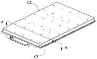
- Fig. 1is an exploded perspective view of a battery box according to the present application.
- FIG. 2is an assembly diagram of FIG. 1.
- FIG. 3is a partially enlarged view of FIG. 2.
- Fig. 4is a view similar to Fig. 3, in which the seal is not shown.
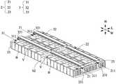
- FIG. 5is a perspective view of an embodiment of a battery box according to the present application, wherein the box body is not shown.
- Fig. 6is a perspective view of another embodiment similar to Fig. 5, in which the box is not shown.
- FIG. 7is a cross-sectional view taken along line A-A of FIG. 2.
- FIG. 8is a cross-sectional view of another embodiment similar to FIG. 7.
- FIG. 9is a perspective view of an embodiment of the first guide plate.
- Fig. 10is a partially enlarged view of Fig. 9.
- the battery case according to the present applicationincludes a case C, a first battery pack 2 and a seal S.
- the battery boxmay further include a second battery pack 3, a first beam b1 and a second beam b2.
- the case Cincludes: a lower case C1; and an upper case C2, which is hermetically mounted on the lower case C1 along the height direction H and encloses the housing space 1 with the lower case C1.
- the lower case C1includes: a bottom wall C11; a first peripheral wall C12 connected to the periphery of the bottom wall C11 and extending toward the upper case C2; and a first flange C13 connected to the first peripheral wall C12 and along the first circumference The upper edge of the wall C12 extends outward.
- the upper box C2includes: a top wall C21, a second peripheral wall C22 connected to the periphery of the top wall C21 and extending toward the lower box C1; and a second flange C23 connected to the second peripheral wall C22 and along the second peripheral wall C22 The lower edge of is extended outwards; wherein, the upper case C2 is mounted on the lower case C1 along the height direction H, and the second flange C23 of the upper case C2 is sealingly connected with the first flange C13 of the lower case C1.
- the storage space 1 of the case Ccontains the first battery pack 2.
- the first battery pack 2includes: a first battery row 21, a first guide plate 22, a first end plate 23, and a second end plate 24.
- the first guide plate 22is located above the first battery row 21; the first end plate 23 and the second end plate 24 are provided on both sides of the width direction W of the first battery row 21.
- the first battery row 21includes a plurality of batteries B arranged side by side along the width direction W, an explosion-proof valve V is provided on the top of each battery B, and all explosion-proof valves V of the first battery row 21 constitute a first explosion-proof valve row 211.
- the first guide plate 22extends in the width direction W and is sealed above the first explosion-proof valve row 211.
- the first guide plate 22 and the upper surface of the first battery row 21form a first passage P1 extending in the width direction W.
- the first guide plate 22includes: a body portion 221; a side portion 222 connected to both sides of the body portion 221 along the length direction L and extending along the first battery row 21; a fixing portion 223 connected to the side portion 222 along the length direction L Extending outward, the fixing portion 223 is hermetically fixed to the upper surface of the first battery row 21.
- the fixing portion 223can be adhered to the upper surface of the first battery row 21 via structural glue. Of course, there are other fixing methods, which can be selected according to specific conditions.
- the first guide plate 22is formed by integral stamping.
- the first guide plate 22is simple to form and easy to install.
- the first end plate 23is provided on one side of the width direction W of the first battery row 21 and is provided with a first concave portion 231 which is located below the height direction H of the first guide plate 22 and is connected to one end of the first passage P1 In communication, an opening O is provided at a position of the box C corresponding to the first concave portion 231.
- the second end plate 24is provided on the other side in the width direction W of the first battery row 21 and is provided with a second concave portion 241 which is located below the height direction H of the first guide plate 22 and is connected to the first passage P1 The other end is in communication, and an opening O is provided at a position of the box C corresponding to the second recess 241.
- the first concave portion 231 of the first end plate 23is recessed inward from the surface of the side facing away from the first battery row 21 and extends in the height direction H to the upper surface of the first end plate 23 to form The first passage P1 communicates.
- the second end plate 24has the same structure as the first end plate 23. As shown in FIG.
- the portion of the second flange C23 of the upper case C2bulges upward in the height direction H to form an opening O corresponding to the first flange C13 of the lower case C1, and of course the opening O is formed in a manner Not limited to this, for example, the portion of the second flange C23 of the upper case C2 bulges upward in the height direction H and the corresponding portion of the first flange C13 of the lower case C1 also bulges downward in the height direction H and The two are joined together to form the opening O; or the corresponding portion of the first flange C13 of the lower case C1 swells down in the height direction H and engages with the second flange C23 of the upper case C2 to form the opening O,
- the specific formation methodcan be selected according to the specific situation.
- the gas generated inside the battery Bwill break through the explosion-proof valve V and will rush out gas and heat, and also carry some steam.
- the gas, heat and steamare collectively referred to as gas production in this article, and the pressure and heat of the gas production Both are relatively high, and the sealing member 3 can be broken by the pressure or high temperature of the generated gas, thereby opening the opening O.
- the sealing member Sseals the opening O corresponding to the box C and is set to be broken to open the opening O. It should be noted that the destruction of the sealing member S is usually due to the failure of the battery B inside the battery B. A large amount of gas and heat will be generated.
- the sealing member Sis an adhesive glue.
- An adsorbentis provided in the first passage P1 formed by the first guide plate 22 and the upper surface of the first battery row 21.
- the adsorbent materialincludes a mixture of sodium bicarbonate, ammonium phosphate and the like.
- the seal SWhen the gas reaches a certain pressure, the seal S is broken or the high-temperature heat carried by the gas melts the seal S to discharge the gas and heat to the outside, thereby It prevents the gas and heat of battery B from accumulating in box C and causes thermal runaway of other battery B and other components, prevents the spread of thermal runaway, and improves the safety performance of the battery box.
- the adsorbent materialcan play the role of flame retardant and lower temperature, and help reduce the thermal runaway diffusion; at the same time, it can absorb moisture and prevent the accumulation of water vapor in the first passage P1.
- first battery rows 21 of the first battery pack 2there are more than two first battery rows 21 of the first battery pack 2 arranged side by side along the length direction L; there are more than two first guide plates 22, and each of the first guide plates 22 is sealingly arranged at the corresponding A first passage P1 is formed above an explosion-proof valve row 211 and the upper surface of the corresponding first battery row 21; there are more than two first recesses 231 of the first end plate 23, and each of the first recesses 231 and the corresponding first One end of one passage P1 communicates; the number of second recesses 241 of the second end plate 24 is two or more, and each second recess 241 communicates with the other end of the corresponding first passage P1.
- the first battery row 21 of the first battery pack 2is shown as two, of course, it is not limited to two, and the first battery row 21 of the first battery pack 2 may also be One or more than two, whether one or more than two, the exhaust path is designed in the same form, and will not be repeated here.
- the first battery pack 2is more than two and arranged along the length direction L, and the battery box further includes: a first beam b1, sandwiched Between two adjacent first battery packs 2, the storage space 1 of the box C is divided into two or more sub-spaces, and each first battery pack 2 is stored in the corresponding sub-space.
- the design of the exhaust path of each battery pack 2 and the function of the exhaust pathare the same as those of the first embodiment, and the description will not be repeated here.
- the design of the first beam b1can increase the overall strength of the box C, and the subspace divided by the first beam b1 is preferably a sealed space, and each first battery pack 2 is housed in the sealed space.
- the battery B in a subspaceis thermally out of control, and high-temperature or high-pressure gas will not diffuse into the remaining sealed space, which further prevents the spread of thermal runaway and further improves the safety performance of the battery box.
- the first battery pack 2includes: a first battery row 21, a first guide plate 22, and a first end plate 23.
- the battery boxfurther includes: a second battery pack 3 arranged side by side with the first battery pack 2 in the width direction W, and the second battery pack 3 includes: a second battery row 31, a second guide plate 32, a third ⁇ 33 ⁇ The end plate 33.
- the first guide plate 22includes: a body portion 221; a side portion 222 connected to both sides of the body portion 221 along the length direction L and extending along the first battery row 21;
- the fixing portion 223is connected to the side portion 222 and extends outward in the longitudinal direction L.
- the fixing portion 223is sealed and fixed to the upper surface of the first battery row 21; the first guide plate 22 further includes a stop portion 224, which is disposed along the width direction W One end of the body portion 221 is connected to the ends of the body portion 221, the side portion 222, and the fixing portion 223, so that the first path P1 formed by the first guide plate 22 and the upper surface of the first battery row 21 is adjacent to the second battery pack 3 is closed at one end and exhausted on the side close to the box C. Except for this, the first battery row 21 and the first end plate 23 of the first battery pack 2 are arranged in the same manner as the first embodiment. This description will not be repeated.
- the stopper 224may be welded to the ends of the main body 221, the side 222, and the fixing portion 223, or may be integrally formed with the main body 221, the side 222, and the fixing portion 223.
- the second battery row 31includes a plurality of batteries B arranged side by side in the width direction W, an explosion-proof valve V is provided on the top of each battery B, and all the explosion-proof valves V of the second battery row 31 constitute a second explosion-proof valve row 311.
- the second guide plate 32extends in the width direction W and is sealed above the second explosion-proof valve row 311.
- the second guide plate 32 and the upper surface of the second battery row 31form a second passage P2 extending in the width direction W.
- the second guide plate 32has the same structure as the first guide plate 22.
- An adsorbentis also provided in the second passage P2 formed by the second guide plate 32 and the upper surface of the second battery row 31.
- the third end plate 33is provided on one side in the width direction W of the second battery row 31 and is provided with a third recess 331 located below the height direction H of the second guide plate 32 and connected to one end of the second passage P2 Connected, the box C is provided with an opening O at a position corresponding to the third recess 331; wherein, the end of the second passage P2 adjacent to the first battery pack 2 is closed; the end of the first passage P1 adjacent to the second battery pack 3 Closed.
- the explosion-proof valve V of the corresponding battery BWhen the explosion-proof valve V of the corresponding battery B is broken due to gas generation inside the battery B, the gas generation and heat of the battery B pass through the explosion-proof valve V, the corresponding first passage P1 or the second passage P2, and the corresponding first recess 231 or the second recess 241 and the corresponding opening O are discharged to the outside of the case C.
- the adsorbent materialcan play the role of flame retardant and temperature reduction, to help reduce the thermal runaway diffusion; at the same time, it can absorb moisture and prevent water from accumulating in the first passage P1 or the second passage P2.
- the first battery pack 2is two or more and arranged in the longitudinal direction L
- the second battery pack 3is two or more and arranged in the longitudinal direction L.
- the battery boxfurther includes: a first beam b1 disposed between two adjacent first battery groups 2 and two adjacent second battery groups 3; a second beam b2 sandwiched between the first battery groups along the width direction W 2 and the second battery pack 3, the first beam b1 and the second beam b2 divide the storage space 1 into a plurality of subspaces, and each first battery pack 2 and each second battery pack 3 are respectively stored in corresponding subspaces .
- the subspaceis a closed space.
- This embodimentis different from the third embodiment in the number of the first battery pack 2 and the second battery pack 3, and the specific exhaust method is the same as that described above, and will not be described here.
- the arrangement of the first beam b1 and the second beam b2improves the overall strength of the battery box, and at the same time divides the storage space into a plurality of closed sub-spaces, preventing the spread and diffusion of thermal runaway, and improving the safety performance of the battery box.
Landscapes
- Chemical & Material Sciences (AREA)
- Chemical Kinetics & Catalysis (AREA)
- Electrochemistry (AREA)
- General Chemical & Material Sciences (AREA)
- Battery Mounting, Suspending (AREA)
- Gas Exhaust Devices For Batteries (AREA)
Abstract
Description
Translated fromChinese本申请涉及电池领域,尤其涉及一种电池箱。The present application relates to the field of batteries, in particular to a battery box.
伴随新能源汽车的蓬勃发展,动力电池系统产品的需求日益增长。在传统的电池包中,经常会由于一个电池的升温或损坏而导致整个电池包出现热失控的情况,现有的设计一般会在电池包上部覆盖防火棉以减缓热失控的热蔓延,该方法可以起到一定的防护作用,但无法从根本上减弱热失控的蔓延,且一旦热蔓延或温度过高,防火棉的覆盖将会阻碍内部气体的流通,影响电池的防爆阀开阀泄气。With the vigorous development of new energy vehicles, the demand for power battery system products is increasing. In the traditional battery pack, the entire battery pack is often thermally runaway due to the heating or damage of a battery. Existing designs generally cover the top of the battery pack with fireproof cotton to slow the thermal runaway. This method It can play a certain protective role, but it cannot fundamentally reduce the spread of thermal runaway. Once the heat spreads or the temperature is too high, the cover of the fireproof cotton will hinder the flow of internal gas and affect the opening of the battery's explosion-proof valve.
发明内容Summary of the invention
鉴于背景技术中存在的问题,本申请的目的在于提供一种电池箱以及车辆,其能够将电池失效时电池内部的产气及热量导出到外部,防止热量的蔓延,提高电池包的安全性。In view of the problems in the background art, the object of the present application is to provide a battery box and a vehicle that can export the gas and heat inside the battery to the outside when the battery fails, prevent the spread of heat, and improve the safety of the battery pack.
为了实现上述目的,本申请提供了一种电池箱,其包括:箱体,包括封闭的收容空间;第一电池组,容置于收容空间中。第一电池组包括:第一电池排,第一电池排包括多个沿宽度方向并排布置的电池,各电池的顶部设有防爆阀,第一电池排的所有防爆阀组成第一防爆阀排;第一导板,沿宽度方向延伸并密封设置在第一防爆阀排的上方,第一导板与第一电池排的上表面形成沿宽度方向延伸的第一通路;第一端板,设置在第一电池排的宽度方向的一侧并设有第一凹部,第一凹部位于第一导板的高度方向的下方并与第一通路的一端连通,箱体的与第一凹部对应的位置处设有开口;电池箱还包括:密封件,密封箱体对应的开口并设置成能够被破坏而使开口打开。In order to achieve the above object, the present application provides a battery box, which includes: a box body, which includes an enclosed storage space; and a first battery pack, which is accommodated in the storage space. The first battery pack includes: a first battery row, the first battery row includes a plurality of batteries arranged side by side in the width direction, an explosion-proof valve is provided on the top of each battery, and all explosion-proof valves of the first battery row constitute the first explosion-proof valve row; The first guide plate extends in the width direction and is sealed above the first explosion-proof valve row. The first guide plate and the upper surface of the first battery row form a first path extending in the width direction; the first end plate is provided in the first A side of the battery row in the width direction is provided with a first concave portion, the first concave portion is located below the height direction of the first guide plate and communicates with one end of the first passage, and the box body is provided with an opening at a position corresponding to the first concave portion The battery box further includes: a sealing member, which seals the opening corresponding to the box body and is arranged to be broken so that the opening is opened.
在一实施例中,第一电池组还包括:第二端板,设置在第一电池排的宽度方向的另一侧并设有第二凹部,第二凹部位于第一导板的高度方向的下方 并与第一通路的另一端连通,箱体的与第二凹部对应的位置处设有开口。In an embodiment, the first battery pack further includes: a second end plate, disposed on the other side in the width direction of the first battery row and provided with a second concave portion, the second concave portion is located below the height direction of the first guide plate It communicates with the other end of the first passage, and the box body is provided with an opening at a position corresponding to the second recess.
在一实施例中,第一电池组的第一电池排为两个以上并沿长度方向并排布置;第一导板为两个以上,各第一导板密封设置在对应的第一防爆阀排的上方并与对应的第一电池排的上表面形成第一通路;第一端板的第一凹部为两个以上,且各第一凹部与对应的第一通路的一端连通;第二端板的第二凹部为两个以上,且各第二凹部与对应的第一通路的另一端连通。In an embodiment, there are more than two first battery rows of the first battery pack and are arranged side by side along the length direction; there are more than two first guide plates, and each first guide plate is sealingly arranged above the corresponding first explosion-proof valve line And form a first passage with the upper surface of the corresponding first battery row; there are more than two first recesses of the first end plate, and each first recess communicates with one end of the corresponding first passage; the first end of the second end plate There are two or more second recesses, and each second recess communicates with the other end of the corresponding first passage.
在一实施例中,电池箱还包括:第二电池组,第二电池组与第一电池组沿宽度方向并排布置,第二电池组包括:第二电池排,第二电池排包括多个沿宽度方向并排布置的电池,各电池的顶部设有防爆阀,第二电池排的所有防爆阀组成第二防爆阀排;第二导板,沿宽度方向延伸并密封设置在第二防爆阀排的上方,第二导板与第二电池排的上表面形成沿宽度方向延伸的第二通路;第三端板,设置在第二电池排的宽度方向的一侧并设有第三凹部,第三凹部位于第二导板的高度方向的下方并与第二通路的一端连通,箱体的与第三凹部对应的位置处设有开口;其中,第二通路的邻近第一电池组的一端封闭;第一通路的邻近第二电池组的一端封闭。In an embodiment, the battery box further includes: a second battery pack, the second battery pack and the first battery pack are arranged side by side in the width direction, the second battery pack includes: a second battery row, the second battery row includes a plurality of edges For batteries arranged side by side in the width direction, the top of each battery is provided with an explosion-proof valve, and all explosion-proof valves in the second battery row constitute a second explosion-proof valve row; the second guide plate extends in the width direction and is sealed above the second explosion-proof valve row , The second guide plate and the upper surface of the second battery row form a second passage extending in the width direction; the third end plate is provided on one side of the second battery row in the width direction and is provided with a third recess, the third recess is located The second guide plate is downward in the height direction and communicates with one end of the second passage, and the box is provided with an opening at a position corresponding to the third recess; wherein, the end of the second passage adjacent to the first battery pack is closed; the first passage The end of the battery adjacent to the second battery is closed.
在一实施例中,第一电池组为两个以上并长度方向排列,第二电池组为两个以上并沿长度方向排列;电池箱还包括:第一梁,设置于相邻两个第一电池组以及相邻两个第二电池组之间;第二梁,沿宽度方向夹设于第一电池组与第二电池组之间,第一梁和第二梁将收容空间分割成多个子空间,各第一电池组和各第二电池组分别收容于对应的子空间中。In an embodiment, the first battery pack is more than two and arranged in the length direction, and the second battery pack is more than two and arranged in the length direction; the battery box further includes: a first beam, which is arranged on two adjacent first Between the battery pack and two adjacent second battery packs; the second beam is sandwiched between the first battery pack and the second battery pack in the width direction, and the first beam and the second beam divide the receiving space into a plurality of sub-units Space, each first battery pack and each second battery pack are housed in corresponding subspaces, respectively.
在一实施例中,第一导板包括:主体部;侧部,沿长度方向连接于主体部的两侧并沿第一电池排延伸;固定部,连接于侧部并沿长度方向向外延伸,固定部密封固定于第一电池排的上表面。In an embodiment, the first guide plate includes: a body portion; a side portion, which is connected to both sides of the body portion along the length direction and extends along the first battery row; a fixing portion, which is connected to the side portion and extends outward along the length direction, The fixing portion is hermetically fixed to the upper surface of the first battery row.
在一实施例中,第一导板还包括:止挡部,沿宽度方向设置于主体部的一端并连接于主体部、侧部和固定部的端部。In an embodiment, the first guide plate further includes: a stopper portion provided at one end of the main body portion in the width direction and connected to the end portions of the main body portion, the side portion, and the fixed portion.
在一实施例中,第一导板与第一电池排的上表面形成的第一通路内设置有吸附材料。In one embodiment, the first guide plate and the first passage formed by the upper surface of the first battery row are provided with an adsorbent material.
在一实施例中,箱体包括:下箱体;以及上箱体,沿高度方向密封安装于下箱体并与下箱体围成收容空间。下箱体包括:底壁;第一周壁,连接于底壁的四周并向上箱体方向延伸;以及第一凸缘,连接于第一周壁并沿第一 周壁的上缘向外延伸。上箱体包括:顶壁,第二周壁,连接于顶壁的四周并向下箱体方向延伸;以及第二凸缘,连接于第二周壁并沿第二周壁的下缘向外延伸;其中,上箱体沿高度方向安装于下箱体,上箱体的第二凸缘与下箱体的第一凸缘密封连接。In an embodiment, the box body includes: a lower box body; and an upper box body, which is hermetically mounted on the lower box body in a height direction and forms a receiving space with the lower box body. The lower box includes: a bottom wall; a first peripheral wall connected to the periphery of the bottom wall and extending toward the upper box; and a first flange connected to the first peripheral wall and extending outward along the upper edge of the first peripheral wall . The upper box includes: a top wall, a second peripheral wall connected to the periphery of the top wall and extending toward the lower box; and a second flange connected to the second peripheral wall and extending outward along the lower edge of the second peripheral wall; , The upper box is mounted on the lower box in the height direction, and the second flange of the upper box is sealingly connected with the first flange of the lower box.
在一实施例中,上箱体的第二凸缘的部分沿高度方向向上鼓出以与下箱体的第一凸缘形成对应的开口。In an embodiment, a portion of the second flange of the upper case bulges upward in the height direction to form an opening corresponding to the first flange of the lower case.
本申请的有益效果如下:在根据本申请的电池箱中,第一通路、第一凹部以及开口的设置为电池失效时电池内部的产气及热量提供了导出通道,使得内部的产气及热量被导出到外部,避免了箱体内产气及热量的累积而导致的热失控的风险,提高了电池箱的安全性能。The beneficial effects of the present application are as follows: In the battery box according to the present application, the settings of the first passage, the first recess and the opening provide an outlet channel for the gas production and heat inside the battery when the battery fails, making the internal gas production and heat It is exported to the outside, which avoids the risk of thermal runaway caused by gas generation and heat accumulation in the box, and improves the safety performance of the battery box.
图1根据本申请的电池箱的立体分解图。Fig. 1 is an exploded perspective view of a battery box according to the present application.
图2是图1的组装图。FIG. 2 is an assembly diagram of FIG. 1.
图3是图2的局部放大图。FIG. 3 is a partially enlarged view of FIG. 2.
图4是与图3类似的视图,其中未示出密封件。Fig. 4 is a view similar to Fig. 3, in which the seal is not shown.
图5是根据本申请的电池箱的一实施例的立体图,其中未示出箱体。5 is a perspective view of an embodiment of a battery box according to the present application, wherein the box body is not shown.
图6是与图5类似的另一实施例的立体图,其中未示出箱体。Fig. 6 is a perspective view of another embodiment similar to Fig. 5, in which the box is not shown.
图7是沿图2的A-A线剖开的截面图。7 is a cross-sectional view taken along line A-A of FIG. 2.
图8是与图7类似的另一实施例的截面图。8 is a cross-sectional view of another embodiment similar to FIG. 7.
图9是第一导板的一实施例的立体图。9 is a perspective view of an embodiment of the first guide plate.
图10是图9的局部放大图。Fig. 10 is a partially enlarged view of Fig. 9.
其中,附图标记说明如下:Among them, the reference signs are described as follows:
C箱体 P1第一通路C box body P1 first channel
C1下箱体 23第一端板C1
C11底壁 231第一凹部Bottom wall of
C12第一周壁 24第二端板C12
C13第一凸缘 241第二凹部C13
C2上箱体 O开口C2 upper box O opening O opening
C21顶壁 S密封件C21 top wall S seals
C22第二周壁 b1第一梁C22 Second Week Wall b1 First Beam
C23第二凸缘 b2第二梁C23 Second flange b2 Second beam
1收容空间 3第二电池组1
2第一电池组 31第二电池排2
21第一电池排 311第二防爆阀排21
B电池 32第二导板
V防爆阀 P2第二通路V explosion-proof valve P2 second channel
211第一防爆阀排 33第三端板211 First explosion-
22第一导板 331第三凹部22
221主体部 L长度方向221 Main body L length direction
222侧部 H高度方向222 side part H height direction
223固定部 W宽度方向223 Fixed part W width direction
224止挡部224 stop
附图示出本申请的实施例,且将理解的是,所公开的实施例仅仅是本申请的示例,本申请可以以各种形式实施,因此,本文公开的具体细节不应被解释为限制,而是仅作为权利要求的基础且作为表示性的基础用于教导本领域普通技术人员以各种方式实施本申请。The drawings illustrate embodiments of the present application, and it will be understood that the disclosed embodiments are merely examples of the present application, and the present application can be implemented in various forms, and therefore, specific details disclosed herein should not be interpreted as limiting Rather, it is only used as a basis for claims and as an expressive basis for teaching one of ordinary skill in the art to implement the application in various ways.
此外,诸如长度方向、高度方向和宽度方向等用于说明本实施例中的电池箱的各构件的操作和构造的指示方向的表述不是绝对的而是相对的,且尽管当电池箱的各构件处于图中所示的位置时这些指示是恰当的,但是当这些位置改变时,这些方向应有不同的解释,以对应所述改变。In addition, expressions such as the length direction, the height direction, and the width direction that are used to describe the operation and configuration of the components of the battery box in this embodiment are not absolute but relative, and although the components of the battery box These indications are appropriate when in the positions shown in the figure, but when these positions change, these directions should be interpreted differently to correspond to the changes.
如图1至图4所示,根据本申请的电池箱包括:箱体C、第一电池组2以及密封件S。电池箱还可包括第二电池组3、第一梁b1和第二梁b2。As shown in FIGS. 1 to 4, the battery case according to the present application includes a case C, a
箱体C包括:下箱体C1;以及上箱体C2,沿高度方向H密封安装于下箱体C1并与下箱体C1围成收容空间1。The case C includes: a lower case C1; and an upper case C2, which is hermetically mounted on the lower case C1 along the height direction H and encloses the housing space 1 with the lower case C1.
下箱体C1包括:底壁C11;第一周壁C12,连接于底壁C11的四周并向上箱体C2方向延伸;以及第一凸缘C13,连接于第一周壁C12并沿第一周壁C12的上缘向外延伸。The lower case C1 includes: a bottom wall C11; a first peripheral wall C12 connected to the periphery of the bottom wall C11 and extending toward the upper case C2; and a first flange C13 connected to the first peripheral wall C12 and along the first circumference The upper edge of the wall C12 extends outward.
上箱体C2包括:顶壁C21,第二周壁C22,连接于顶壁C21的四周并向下箱体C1方向延伸;以及第二凸缘C23,连接于第二周壁C22并沿第二周壁C22的下缘向外延伸;其中,上箱体C2沿高度方向H安装于下箱体C1,上箱体C2的第二凸缘C23与下箱体C1的第一凸缘C13密封连接。The upper box C2 includes: a top wall C21, a second peripheral wall C22 connected to the periphery of the top wall C21 and extending toward the lower box C1; and a second flange C23 connected to the second peripheral wall C22 and along the second peripheral wall C22 The lower edge of is extended outwards; wherein, the upper case C2 is mounted on the lower case C1 along the height direction H, and the second flange C23 of the upper case C2 is sealingly connected with the first flange C13 of the lower case C1.
具体地,电池箱内的第一电池组2、第二电池组3、第一梁b1和第二梁b2组合方式有多种实施例,下面根据不同实施例进行具体说明。Specifically, there are various embodiments for the combination of the
在第一实施例中,如图5和图8所示,箱体C的收容空间1收容有第一电池组2。In the first embodiment, as shown in FIGS. 5 and 8, the storage space 1 of the case C contains the
第一电池组2包括:第一电池排21、第一导板22、第一端板23和第二端板24。第一导板22位于第一电池排21的上方;第一端板23和第二端板24设置在第一电池排21的宽度方向W的两侧。The
第一电池排21包括多个沿宽度方向W并排布置的电池B,各电池B的顶部设有防爆阀V,第一电池排21的所有防爆阀V组成第一防爆阀排211。第一导板22沿宽度方向W延伸并密封设置在第一防爆阀排211的上方,第一导板22与第一电池排21的上表面形成沿宽度方向W延伸的第一通路P1。The
第一导板22包括:主体部221;侧部222,沿长度方向L连接于主体部221的两侧并沿第一电池排21延伸;固定部223,连接于侧部222并沿长度方向L向外延伸,固定部223密封固定于第一电池排21的上表面。固定部223可经由结构胶粘接于第一电池排21的上表面,当然还有其它的固定方式,可根据具体情况进行选择。第一导板22经由一体冲压成型。第一导板22成型简单,且安装方便。The
第一端板23设置在第一电池排21的宽度方向W的一侧并设有第一凹部231,第一凹部231位于第一导板22的高度方向H的下方并与第一通路P1的一端连通,箱体C的与第一凹部231对应的位置处设有开口O。第二端板24设置在第一电池排21的宽度方向W的另一侧并设有第二凹部241,第二凹部241位于第一导板22的高度方向H的下方并与第一通路P1的另一端连通,箱体C的与第二凹部241对应的位置处设有开口O。第一端板23的第一凹部231从背离第一电池排21的一侧的表面向内凹入且沿高度方向H延伸至第一端板23的上表面,以与第一导板22形成的第一通路P1连通。第二端板24与第一端板23的结构相同。如图4所示,上箱体C2的第二凸 缘C23的部分沿高度方向H向上鼓出以与下箱体C1的第一凸缘C13形成对应的开口O,当然开口O的形成方式并不限于此,例如,上箱体C2的第二凸缘C23的部分沿高度方向H向上鼓出且下箱体C1的第一凸缘C13的对应的部分也沿高度方向H向下鼓出且二者接合在一起而形成开口O;或者下箱体C1的第一凸缘C13的对应的部分沿高度方向H向下鼓出并与上箱体C2的第二凸缘C23接合形成开口O,具体的形成方式可根据具体情况进行选择。通常电池B失效时电池B内部的产气将冲破防爆阀V并会冲出气体、热量,同时还会携带一些蒸汽,气体、热量和蒸汽在本文中统称为产气,产气的压力和热量都相对较高,而密封件3可被产气的压力或高温所破坏,从而使开口O打开。如图3所示,密封件S密封箱体C对应的开口O并设置成能够被破坏而使开口O打开,需要注意的是,密封件S的破坏通常是由于电池B失效时,电池B内部会产生大量的气体和热量,当气体和热量积聚到一定程度时将冲破电池B的防爆阀V,冲出防爆阀V的气体和热量将沿第一通路P1导出到开口O处,而密封件S可以被导出的气体的压力冲破或者热量所熔化,从而使得密封件S被破坏而使开口O打开。优选地,密封件S为粘接胶。第一导板22与第一电池排21的上表面形成的第一通路P1内设置有吸附材料。吸附材料包括碳酸氢钠、磷酸铵盐等混合物。The
在该实施例中,如图8所示,当电池B的防爆阀V因电池B内部产气而被冲破时,该电池B的防爆阀V被冲破的部位、第一通路P1、第一端板23的第一凹部231、第二端板24的第二凹部241、箱体的开口O形成连通的排气通道,电池B内部的经由冲破的防爆阀V释放出的产气和热量经所述排气通道被导出到箱体C两侧的开口O处,气体达到一定压力时冲破密封件S或者气体所携带的高温热量将密封件S熔化从而将产气和热量排出到外部,由此,防止了电池B的产气和热量在箱体C内的堆积而引起其他电池B等部件的热失控,阻止了热失控的蔓延,提高了电池箱的安全性能。此外,吸附材料能够起到阻燃和降低温度的作用,起到辅助减少热失控扩散的作用;同时还能够吸潮防水,防止第一通路P1内积聚水汽。In this embodiment, as shown in FIG. 8, when the explosion-proof valve V of the battery B is broken due to gas generation inside the battery B, the portion where the explosion-proof valve V of the battery B is broken, the first passage P1, the first end The first recessed
在第一实施例中,第一电池组2的第一电池排21为两个以上并沿长度方向L并排布置;第一导板22为两个以上,各第一导板22密封设置在对应的第一防爆阀排211的上方并与对应的第一电池排21的上表面形成第一通 路P1;第一端板23的第一凹部231为两个以上,且各第一凹部231与对应的第一通路P1的一端连通;第二端板24的第二凹部241为两个以上,且各第二凹部241与对应的第一通路P1的另一端连通。在本实施例中,如图5所示,第一电池组2的第一电池排21以两个示出,当然并不限于两个,第一电池组2的第一电池排21也可以为一个或者多余两个,无论一个或者多余两个,排气路径均以相同的形式进行设计,在此不再重复说明。In the first embodiment, there are more than two
在第二实施例(未示出)中,与第一实施例不同的是,第一电池组2为两个以上并沿长度方向L排列,且电池箱还包括:第一梁b1,夹设于相邻两个第一电池组2之间并将箱体C的收容空间1分割为两个以上的子空间,各第一电池组2收容于对应的子空间中。各电池组2的排气路径的设计以及排气路径的作用与第一实施例相同,在此不再重复说明。注意的是,第一梁b1的设计能够增加箱体C的整体强度,且由第一梁b1分割的子空间优选为密封的空间,各第一电池组2收容在密封的空间中,如果其中一个子空间内的电池B发生热失控,高温或高压气体不会扩散到剩余的密封的空间中,进一步防止了热失控的蔓延,且进一步提高了电池箱的安全性能。In the second embodiment (not shown), different from the first embodiment, the
在第三实施例中,如图6和图7所示,第一电池组2包括:第一电池排21、第一导板22、第一端板23。电池箱还包括:第二电池组3,第二电池组3与第一电池组2沿宽度方向W并排布置,且第二电池组3包括:第二电池排31、第二导板32、第三端板33。In the third embodiment, as shown in FIGS. 6 and 7, the
在该实施例中,如图9和图10所示,第一导板22包括:主体部221;侧部222,沿长度方向L连接于主体部221的两侧并沿第一电池排21延伸;固定部223,连接于侧部222并沿长度方向L向外延伸,固定部223密封固定于第一电池排21的上表面;第一导板22还包括止挡部224,沿宽度方向W设置于主体部221的一端并连接于主体部221、侧部222和固定部223的端部,以使第一导板22与第一电池排21的上表面形成的第一通路P1在邻近第二电池组3的一端封闭而在靠近箱体C的一侧排气,除此之外,第一电池组2的第一电池排21、第一端板23均与第一实施例的设置形式相同,在此不再重复说明。止挡部224可以焊接连接于主体部221、侧部222和固定部223的端部,也可以与主体部221、侧部222和固定部223一体成型。In this embodiment, as shown in FIGS. 9 and 10, the
第二电池排31包括多个沿宽度方向W并排布置的电池B,各电池B的 顶部设有防爆阀V,第二电池排31的所有防爆阀V组成第二防爆阀排311。The
第二导板32沿宽度方向W延伸并密封设置在第二防爆阀排311的上方,第二导板32与第二电池排31的上表面形成沿宽度方向W延伸的第二通路P2。第二导板32与第一导板22的结构相同。第二导板32与第二电池排31的上表面形成的第二通路P2内也设置有吸附材料。The
第三端板33设置在第二电池排31的宽度方向W的一侧并设有第三凹部331,第三凹部331位于第二导板32的高度方向H的下方并与第二通路P2的一端连通,箱体C的与第三凹部331对应的位置处设有开口O;其中,第二通路P2的邻近第一电池组2的一端封闭;第一通路P1的邻近第二电池组3的一端封闭。The
当对应的电池B的防爆阀V因电池B内部产气而被冲破时,该电池B的产气和热量经由防爆阀V、对应的第一通路P1或第二通路P2、对应的第一凹部231或第二凹部241、对应的开口O排出到箱体C的外部。由此,防止了电池B的产气和热量在箱体C内的堆积而引起其他电池B等部件的热失控,阻止了热失控的蔓延,提高了电池箱的安全性能。此外,吸附材料能够起到阻燃和降低温度的作用,起到辅助减少热失控扩散的作用;同时还能够吸潮防水,防止第一通路P1或第二通路P2内积聚水汽。When the explosion-proof valve V of the corresponding battery B is broken due to gas generation inside the battery B, the gas generation and heat of the battery B pass through the explosion-proof valve V, the corresponding first passage P1 or the second passage P2, and the corresponding
在第四实施例中,如图1所示,第一电池组2为两个以上并长度方向L排列,第二电池组3为两个以上并沿长度方向L排列。电池箱还包括:第一梁b1,设置于相邻两个第一电池组2以及相邻两个第二电池组3之间;第二梁b2,沿宽度方向W夹设于第一电池组2与第二电池组3之间,第一梁b1和第二梁b2将收容空间1分割成多个子空间,各第一电池组2和各第二电池组3分别收容于对应的子空间中。优选地,子空间为封闭的空间。该实施例与第三实施例在第一电池组2和第二电池组3的数量不同,具体的排气方式与上面所述的相同,在此不再说明。此外第一梁b1和第二梁b2的设置提高了电池箱的整体强度,同时将收容空间分割成多个封闭的子空间,防止了热失控的蔓延和扩散,提高了电池箱的安全性能。In the fourth embodiment, as shown in FIG. 1, the
上面详细的说明描述多个示范性实施例,但本文不意欲限制到明确公开的组合。因此,除非另有说明,本文所公开的各种特征可以组合在一起而形成出于简明目的而未示出的多个另外组合。The above detailed description describes various exemplary embodiments, but this document is not intended to be limited to the explicitly disclosed combinations. Therefore, unless stated otherwise, the various features disclosed herein may be combined together to form multiple additional combinations not shown for simplicity.
Claims (10)
Translated fromChinesePriority Applications (2)
| Application Number | Priority Date | Filing Date | Title |
|---|---|---|---|
| EP19903399.4AEP3799150B1 (en) | 2018-12-27 | 2019-12-17 | Battery box |
| US17/125,998US11949114B2 (en) | 2018-12-27 | 2020-12-17 | Battery box |
Applications Claiming Priority (2)
| Application Number | Priority Date | Filing Date | Title |
|---|---|---|---|
| CN201822224310.8UCN209183604U (en) | 2018-12-27 | 2018-12-27 | battery box |
| CN201822224310.8 | 2018-12-27 |
Related Child Applications (1)
| Application Number | Title | Priority Date | Filing Date |
|---|---|---|---|
| US17/125,998ContinuationUS11949114B2 (en) | 2018-12-27 | 2020-12-17 | Battery box |
Publications (1)
| Publication Number | Publication Date |
|---|---|
| WO2020135152A1true WO2020135152A1 (en) | 2020-07-02 |
Family
ID=67378022
Family Applications (1)
| Application Number | Title | Priority Date | Filing Date |
|---|---|---|---|
| PCT/CN2019/125990CeasedWO2020135152A1 (en) | 2018-12-27 | 2019-12-17 | Battery box |
Country Status (4)
| Country | Link |
|---|---|
| US (1) | US11949114B2 (en) |
| EP (1) | EP3799150B1 (en) |
| CN (1) | CN209183604U (en) |
| WO (1) | WO2020135152A1 (en) |
Cited By (9)
| Publication number | Priority date | Publication date | Assignee | Title |
|---|---|---|---|---|
| CN113594623A (en)* | 2021-08-11 | 2021-11-02 | 蜂巢能源科技有限公司 | Explosion-proof valve for battery pack |
| EP4080662A4 (en)* | 2020-09-14 | 2023-12-27 | Contemporary Amperex Technology Co., Limited | Battery, electric device, and manufacturing method and system for battery |
| EP4064435A4 (en)* | 2020-09-30 | 2024-04-24 | Contemporary Amperex Technology Co., Limited | Battery, device, and preparation method and preparation device for battery |
| US11990592B2 (en) | 2020-11-17 | 2024-05-21 | Contemporary Amperex Technology Co., Limited | Battery, apparatus using battery, and manufacturing method and manufacturing device of battery |
| US12034176B2 (en) | 2020-09-30 | 2024-07-09 | Contemporary Amperex Technology Co., Limited | Battery, apparatus, and preparation method and preparation apparatus of battery |
| US12068468B2 (en) | 2020-12-24 | 2024-08-20 | Contemporary Amperex Technology Co., Limited | Battery module and manufacturing method and device thereof, battery pack, and power consumption apparatus |
| US12113162B2 (en) | 2020-04-30 | 2024-10-08 | Contemporary Amperex Technology Co., Limited | Battery comprising first-type battery cell group and second-type battery cell group which are connected in series, apparatus, and method and device for manufacturing battery |
| US12132217B2 (en) | 2020-07-29 | 2024-10-29 | Contemporary Amperex Technology Co., Limited | Battery module, battery pack, apparatus, and method and device for manufacturing battery module |
| US12176509B2 (en) | 2020-09-30 | 2024-12-24 | Contemporary Amperex Technology (Hong Kong) Limited | Battery, apparatus, and preparation method and preparation apparatus of battery |
Families Citing this family (17)
| Publication number | Priority date | Publication date | Assignee | Title |
|---|---|---|---|---|
| CN209183604U (en)* | 2018-12-27 | 2019-07-30 | 宁德时代新能源科技股份有限公司 | battery box |
| CN112331981B (en)* | 2019-10-15 | 2021-09-17 | 宁德时代新能源科技股份有限公司 | Battery pack and vehicle |
| CN112331997B (en)* | 2019-10-15 | 2021-11-12 | 宁德时代新能源科技股份有限公司 | Battery packs and vehicles |
| CN114982052A (en)* | 2020-02-18 | 2022-08-30 | 旭化成株式会社 | Lithium-ion battery module |
| KR102814566B1 (en)* | 2020-04-01 | 2025-05-29 | 주식회사 엘지에너지솔루션 | Battery Module Comprising Gas Barrier Structure |
| CN112787020B (en)* | 2021-03-11 | 2025-04-25 | 蔚来汽车科技(安徽)有限公司 | Power battery pack with thermal insulation component |
| CN113113740A (en)* | 2021-03-26 | 2021-07-13 | 厦门海辰新能源科技有限公司 | Battery module and energy storage system |
| KR102773592B1 (en)* | 2021-05-17 | 2025-02-25 | 주식회사 엘지에너지솔루션 | Battery pack having a gas venting path |
| CN113659279B (en)* | 2021-08-13 | 2023-05-12 | 蜂巢能源科技股份有限公司 | Explosion-proof device for battery pack and battery pack |
| EP4228069A1 (en)* | 2022-02-14 | 2023-08-16 | Samsung SDI Co., Ltd. | Battery pack, electric vehicle and method for assembling a battery pack |
| US12275298B2 (en) | 2022-03-23 | 2025-04-15 | Ford Global Technologies, Llc | Traction battery packs with cell-to-pack battery systems housed within irregularly shaped enclosures |
| US12374750B2 (en) | 2022-03-23 | 2025-07-29 | Ford Global Technologies, Llc | Traction battery pack assembling method |
| US12230826B2 (en) | 2022-03-23 | 2025-02-18 | Ford Global Technologies, Llc | Methods for assembling traction battery packs |
| US12424695B2 (en) | 2022-03-23 | 2025-09-23 | Ford Global Technologies, Llc | Retention assemblies for traction battery packs with cell-to-pack battery systems |
| JP2025504497A (en)* | 2022-07-22 | 2025-02-12 | 寧徳時代新能源科技股▲分▼有限公司 | Batteries and power-consuming devices |
| CN115693008A (en)* | 2022-11-07 | 2023-02-03 | 中创新航科技股份有限公司 | Battery pack |
| CN117080674B (en)* | 2023-10-17 | 2024-01-26 | 厦门海辰储能科技股份有限公司 | Battery pack and electric equipment |
Citations (5)
| Publication number | Priority date | Publication date | Assignee | Title |
|---|---|---|---|---|
| CN102088104A (en)* | 2009-11-19 | 2011-06-08 | Sb锂摩托有限公司 | Battery pack, vehicle including the same, and method for manufacturing the battery pack |
| JP2012079510A (en)* | 2010-09-30 | 2012-04-19 | Gs Yuasa Corp | Battery module and battery pack |
| CN203466244U (en)* | 2013-09-24 | 2014-03-05 | 宁德新能源科技有限公司 | Power battery module and safety protection device thereof |
| CN204651372U (en)* | 2015-06-05 | 2015-09-16 | 宁德时代新能源科技有限公司 | For the cover assembly of battery modules |
| CN209183604U (en)* | 2018-12-27 | 2019-07-30 | 宁德时代新能源科技股份有限公司 | battery box |
Family Cites Families (12)
| Publication number | Priority date | Publication date | Assignee | Title |
|---|---|---|---|---|
| US20030232236A1 (en)* | 2002-06-14 | 2003-12-18 | Mitchell Porter H. | Battery package vent |
| US20050147874A1 (en)* | 2003-12-10 | 2005-07-07 | Johnson Controls Technolgy Company | Venting system for battery |
| KR100888283B1 (en)* | 2006-10-23 | 2009-03-10 | 주식회사 엘지화학 | Secondary battery pack with excellent structural stability |
| WO2010035407A1 (en)* | 2008-09-26 | 2010-04-01 | パナソニック株式会社 | Lead acid battery manufacturing method and lead acid battery |
| DE102009018787A1 (en)* | 2009-04-24 | 2010-10-28 | Akasol Engineering Gmbh | battery module |
| US8734978B2 (en) | 2009-11-05 | 2014-05-27 | Samsung Sdi Co., Ltd. | Battery pack |
| WO2012014348A1 (en)* | 2010-07-28 | 2012-02-02 | パナソニック株式会社 | Cell module and cell pack |
| WO2012131837A1 (en)* | 2011-03-25 | 2012-10-04 | 日立ビークルエナジー株式会社 | Battery block and power supply device |
| KR20150066077A (en)* | 2013-12-06 | 2015-06-16 | 삼성에스디아이 주식회사 | Battery module |
| JP6245038B2 (en)* | 2014-03-31 | 2017-12-13 | 株式会社Gsユアサ | Power storage device |
| DE102016118753A1 (en)* | 2016-10-04 | 2018-04-05 | Johnson Controls Advanced Power Solutions Gmbh | ENERGY STORAGE SYSTEM |
| US20180138478A1 (en)* | 2016-11-14 | 2018-05-17 | Anhui Xinen Technology Co., Ltd. | Alleviating explosion propagation in a battery module |
- 2018
- 2018-12-27CNCN201822224310.8Upatent/CN209183604U/enactiveActive
- 2019
- 2019-12-17WOPCT/CN2019/125990patent/WO2020135152A1/ennot_activeCeased
- 2019-12-17EPEP19903399.4Apatent/EP3799150B1/enactiveActive
- 2020
- 2020-12-17USUS17/125,998patent/US11949114B2/enactiveActive
Patent Citations (5)
| Publication number | Priority date | Publication date | Assignee | Title |
|---|---|---|---|---|
| CN102088104A (en)* | 2009-11-19 | 2011-06-08 | Sb锂摩托有限公司 | Battery pack, vehicle including the same, and method for manufacturing the battery pack |
| JP2012079510A (en)* | 2010-09-30 | 2012-04-19 | Gs Yuasa Corp | Battery module and battery pack |
| CN203466244U (en)* | 2013-09-24 | 2014-03-05 | 宁德新能源科技有限公司 | Power battery module and safety protection device thereof |
| CN204651372U (en)* | 2015-06-05 | 2015-09-16 | 宁德时代新能源科技有限公司 | For the cover assembly of battery modules |
| CN209183604U (en)* | 2018-12-27 | 2019-07-30 | 宁德时代新能源科技股份有限公司 | battery box |
Non-Patent Citations (1)
| Title |
|---|
| See also references ofEP3799150A4* |
Cited By (12)
| Publication number | Priority date | Publication date | Assignee | Title |
|---|---|---|---|---|
| US12113162B2 (en) | 2020-04-30 | 2024-10-08 | Contemporary Amperex Technology Co., Limited | Battery comprising first-type battery cell group and second-type battery cell group which are connected in series, apparatus, and method and device for manufacturing battery |
| US12272780B2 (en) | 2020-04-30 | 2025-04-08 | Contemporary Amperex Technology Co., Limited | Battery module, apparatus, battery pack, and method and device for manufacturing battery module |
| US12132217B2 (en) | 2020-07-29 | 2024-10-29 | Contemporary Amperex Technology Co., Limited | Battery module, battery pack, apparatus, and method and device for manufacturing battery module |
| EP4080662A4 (en)* | 2020-09-14 | 2023-12-27 | Contemporary Amperex Technology Co., Limited | Battery, electric device, and manufacturing method and system for battery |
| US12218378B2 (en) | 2020-09-14 | 2025-02-04 | Contemporary Amperex Technology (Hong Kong) Limited | Battery, electric device, manufacturing method and manufacturing system for battery |
| EP4064435A4 (en)* | 2020-09-30 | 2024-04-24 | Contemporary Amperex Technology Co., Limited | Battery, device, and preparation method and preparation device for battery |
| US12002984B2 (en) | 2020-09-30 | 2024-06-04 | Contemporary Amperex Technology Co., Limited | Battery, apparatus, and preparation method and preparation apparatus of battery |
| US12034176B2 (en) | 2020-09-30 | 2024-07-09 | Contemporary Amperex Technology Co., Limited | Battery, apparatus, and preparation method and preparation apparatus of battery |
| US12176509B2 (en) | 2020-09-30 | 2024-12-24 | Contemporary Amperex Technology (Hong Kong) Limited | Battery, apparatus, and preparation method and preparation apparatus of battery |
| US11990592B2 (en) | 2020-11-17 | 2024-05-21 | Contemporary Amperex Technology Co., Limited | Battery, apparatus using battery, and manufacturing method and manufacturing device of battery |
| US12068468B2 (en) | 2020-12-24 | 2024-08-20 | Contemporary Amperex Technology Co., Limited | Battery module and manufacturing method and device thereof, battery pack, and power consumption apparatus |
| CN113594623A (en)* | 2021-08-11 | 2021-11-02 | 蜂巢能源科技有限公司 | Explosion-proof valve for battery pack |
Also Published As
| Publication number | Publication date |
|---|---|
| US11949114B2 (en) | 2024-04-02 |
| EP3799150A4 (en) | 2021-10-06 |
| EP3799150B1 (en) | 2022-10-26 |
| CN209183604U (en) | 2019-07-30 |
| EP3799150A1 (en) | 2021-03-31 |
| US20210104798A1 (en) | 2021-04-08 |
Similar Documents
| Publication | Publication Date | Title |
|---|---|---|
| WO2020135152A1 (en) | Battery box | |
| JP7513710B2 (en) | Battery pack and vehicle | |
| CN215816098U (en) | Battery pack thermal runaway protection system and battery pack | |
| CN112331981B (en) | Battery pack and vehicle | |
| WO2020133660A1 (en) | Battery pack | |
| JP7642781B2 (en) | Battery Device | |
| WO2021088570A1 (en) | Battery pack and apparatus | |
| KR102665192B1 (en) | Battery pack and device including the same | |
| WO2020133659A1 (en) | Battery pack | |
| WO2019127957A1 (en) | Battery module | |
| WO2019174085A1 (en) | Battery module and battery pack | |
| WO2020215443A1 (en) | Upper cover assembly and battery pack | |
| CN114006099A (en) | A battery module and battery pack for delaying heat diffusion | |
| CN115101885A (en) | Directional exhaust battery module, battery box and battery package | |
| CN111668423A (en) | Battery modules, power battery packs and vehicles | |
| WO2024175005A1 (en) | Battery and power device | |
| EP4456286A1 (en) | Battery pack | |
| JP2012199186A (en) | Battery module | |
| WO2024109418A1 (en) | Battery pack and automobile | |
| WO2024179041A1 (en) | Battery tray and battery pack | |
| CN112366400B (en) | Battery trays, power battery packs and vehicles | |
| JP5235981B2 (en) | New battery safety valve | |
| CN221102295U (en) | Battery pack | |
| WO2025020860A1 (en) | Battery tray, battery pack, and vehicle | |
| WO2024199311A1 (en) | Battery pack |
Legal Events
| Date | Code | Title | Description |
|---|---|---|---|
| 121 | Ep: the epo has been informed by wipo that ep was designated in this application | Ref document number:19903399 Country of ref document:EP Kind code of ref document:A1 | |
| ENP | Entry into the national phase | Ref document number:2019903399 Country of ref document:EP Effective date:20201218 | |
| NENP | Non-entry into the national phase | Ref country code:DE |