WO2020133423A1 - Optical fiber connector, prefabricated optical fiber, adapter, optical fiber box and optical fiber connection assembly - Google Patents
Optical fiber connector, prefabricated optical fiber, adapter, optical fiber box and optical fiber connection assemblyDownload PDFInfo
- Publication number
- WO2020133423A1 WO2020133423A1PCT/CN2018/125659CN2018125659WWO2020133423A1WO 2020133423 A1WO2020133423 A1WO 2020133423A1CN 2018125659 WCN2018125659 WCN 2018125659WWO 2020133423 A1WO2020133423 A1WO 2020133423A1
- Authority
- WO
- WIPO (PCT)
- Prior art keywords
- optical fiber
- connection
- fiber connector
- locking
- adapter
- Prior art date
- Legal status (The legal status is an assumption and is not a legal conclusion. Google has not performed a legal analysis and makes no representation as to the accuracy of the status listed.)
- Ceased
Links
Images


Classifications
- G—PHYSICS
- G02—OPTICS
- G02B—OPTICAL ELEMENTS, SYSTEMS OR APPARATUS
- G02B6/00—Light guides; Structural details of arrangements comprising light guides and other optical elements, e.g. couplings
- G02B6/24—Coupling light guides
- G02B6/36—Mechanical coupling means
- G02B6/38—Mechanical coupling means having fibre to fibre mating means
- G02B6/3807—Dismountable connectors, i.e. comprising plugs
- G02B6/3873—Connectors using guide surfaces for aligning ferrule ends, e.g. tubes, sleeves, V-grooves, rods, pins, balls
- G02B6/3874—Connectors using guide surfaces for aligning ferrule ends, e.g. tubes, sleeves, V-grooves, rods, pins, balls using tubes, sleeves to align ferrules
- G02B6/3878—Connectors using guide surfaces for aligning ferrule ends, e.g. tubes, sleeves, V-grooves, rods, pins, balls using tubes, sleeves to align ferrules comprising a plurality of ferrules, branching and break-out means
- G02B6/3879—Linking of individual connector plugs to an overconnector, e.g. using clamps, clips, common housings comprising several individual connector plugs
- G—PHYSICS
- G02—OPTICS
- G02B—OPTICAL ELEMENTS, SYSTEMS OR APPARATUS
- G02B6/00—Light guides; Structural details of arrangements comprising light guides and other optical elements, e.g. couplings
- G02B6/24—Coupling light guides
- G02B6/36—Mechanical coupling means
- G02B6/38—Mechanical coupling means having fibre to fibre mating means
- G02B6/3807—Dismountable connectors, i.e. comprising plugs
- G02B6/381—Dismountable connectors, i.e. comprising plugs of the ferrule type, e.g. fibre ends embedded in ferrules, connecting a pair of fibres
- G02B6/3825—Dismountable connectors, i.e. comprising plugs of the ferrule type, e.g. fibre ends embedded in ferrules, connecting a pair of fibres with an intermediate part, e.g. adapter, receptacle, linking two plugs
- G—PHYSICS
- G02—OPTICS
- G02B—OPTICAL ELEMENTS, SYSTEMS OR APPARATUS
- G02B6/00—Light guides; Structural details of arrangements comprising light guides and other optical elements, e.g. couplings
- G02B6/24—Coupling light guides
- G02B6/36—Mechanical coupling means
- G02B6/38—Mechanical coupling means having fibre to fibre mating means
- G02B6/3807—Dismountable connectors, i.e. comprising plugs
- G02B6/3833—Details of mounting fibres in ferrules; Assembly methods; Manufacture
- G02B6/3847—Details of mounting fibres in ferrules; Assembly methods; Manufacture with means preventing fibre end damage, e.g. recessed fibre surfaces
- G02B6/3849—Details of mounting fibres in ferrules; Assembly methods; Manufacture with means preventing fibre end damage, e.g. recessed fibre surfaces using mechanical protective elements, e.g. caps, hoods, sealing membranes
- G—PHYSICS
- G02—OPTICS
- G02B—OPTICAL ELEMENTS, SYSTEMS OR APPARATUS
- G02B6/00—Light guides; Structural details of arrangements comprising light guides and other optical elements, e.g. couplings
- G02B6/24—Coupling light guides
- G02B6/36—Mechanical coupling means
- G02B6/38—Mechanical coupling means having fibre to fibre mating means
- G02B6/3807—Dismountable connectors, i.e. comprising plugs
- G02B6/3869—Mounting ferrules to connector body, i.e. plugs
- G02B6/387—Connector plugs comprising two complementary members, e.g. shells, caps, covers, locked together
- G—PHYSICS
- G02—OPTICS
- G02B—OPTICAL ELEMENTS, SYSTEMS OR APPARATUS
- G02B6/00—Light guides; Structural details of arrangements comprising light guides and other optical elements, e.g. couplings
- G02B6/24—Coupling light guides
- G02B6/36—Mechanical coupling means
- G02B6/38—Mechanical coupling means having fibre to fibre mating means
- G02B6/3807—Dismountable connectors, i.e. comprising plugs
- G02B6/3887—Anchoring optical cables to connector housings, e.g. strain relief features
- G02B6/3888—Protection from over-extension or over-compression
- G—PHYSICS
- G02—OPTICS
- G02B—OPTICAL ELEMENTS, SYSTEMS OR APPARATUS
- G02B6/00—Light guides; Structural details of arrangements comprising light guides and other optical elements, e.g. couplings
- G02B6/24—Coupling light guides
- G02B6/36—Mechanical coupling means
- G02B6/38—Mechanical coupling means having fibre to fibre mating means
- G02B6/3807—Dismountable connectors, i.e. comprising plugs
- G02B6/3897—Connectors fixed to housings, casing, frames or circuit boards
- G—PHYSICS
- G02—OPTICS
- G02B—OPTICAL ELEMENTS, SYSTEMS OR APPARATUS
- G02B6/00—Light guides; Structural details of arrangements comprising light guides and other optical elements, e.g. couplings
- G02B6/24—Coupling light guides
- G02B6/36—Mechanical coupling means
- G02B6/38—Mechanical coupling means having fibre to fibre mating means
- G02B6/3807—Dismountable connectors, i.e. comprising plugs
- G02B6/381—Dismountable connectors, i.e. comprising plugs of the ferrule type, e.g. fibre ends embedded in ferrules, connecting a pair of fibres
- G02B6/3818—Dismountable connectors, i.e. comprising plugs of the ferrule type, e.g. fibre ends embedded in ferrules, connecting a pair of fibres of a low-reflection-loss type
- G02B6/3821—Dismountable connectors, i.e. comprising plugs of the ferrule type, e.g. fibre ends embedded in ferrules, connecting a pair of fibres of a low-reflection-loss type with axial spring biasing or loading means
- G—PHYSICS
- G02—OPTICS
- G02B—OPTICAL ELEMENTS, SYSTEMS OR APPARATUS
- G02B6/00—Light guides; Structural details of arrangements comprising light guides and other optical elements, e.g. couplings
- G02B6/24—Coupling light guides
- G02B6/36—Mechanical coupling means
- G02B6/38—Mechanical coupling means having fibre to fibre mating means
- G02B6/3807—Dismountable connectors, i.e. comprising plugs
- G02B6/3887—Anchoring optical cables to connector housings, e.g. strain relief features
- G02B6/3889—Anchoring optical cables to connector housings, e.g. strain relief features using encapsulation for protection, e.g. adhesive, molding or casting resin
- G—PHYSICS
- G02—OPTICS
- G02B—OPTICAL ELEMENTS, SYSTEMS OR APPARATUS
- G02B6/00—Light guides; Structural details of arrangements comprising light guides and other optical elements, e.g. couplings
- G02B6/24—Coupling light guides
- G02B6/36—Mechanical coupling means
- G02B6/38—Mechanical coupling means having fibre to fibre mating means
- G02B6/3807—Dismountable connectors, i.e. comprising plugs
- G02B6/389—Dismountable connectors, i.e. comprising plugs characterised by the method of fastening connecting plugs and sockets, e.g. screw- or nut-lock, snap-in, bayonet type
- G02B6/3891—Bayonet type
- G—PHYSICS
- G02—OPTICS
- G02B—OPTICAL ELEMENTS, SYSTEMS OR APPARATUS
- G02B6/00—Light guides; Structural details of arrangements comprising light guides and other optical elements, e.g. couplings
- G02B6/24—Coupling light guides
- G02B6/36—Mechanical coupling means
- G02B6/38—Mechanical coupling means having fibre to fibre mating means
- G02B6/3807—Dismountable connectors, i.e. comprising plugs
- G02B6/389—Dismountable connectors, i.e. comprising plugs characterised by the method of fastening connecting plugs and sockets, e.g. screw- or nut-lock, snap-in, bayonet type
- G02B6/3893—Push-pull type, e.g. snap-in, push-on
Definitions
- the present applicationrelates to an optical fiber connector, prefabricated optical fiber, adapter, optical fiber box and optical fiber connection assembly.
- Fiber-optic pre-connected productsare equipped with optical fiber connectors at both ends of the home optical cable, and matched fiber adapters are also provided on the corresponding fiber distribution box and user terminal box.
- the traditional optical fiber connector and the optical fiber adapterare locked with each other by the screw connection structure between the two.
- This connection methodrequires the optical fiber connector to rotate many times during the locking and disassembly process, which is troublesome to operate, and it is easy to be locked in place and easy to loose due to insufficient manual tightening force of the operator, resulting in the fiber connector and the fiber adapter. The reliability of the connection is poor.
- Embodiments of the present applicationprovide an optical fiber connector, a prefabricated optical fiber using the optical fiber connector, an adapter, an optical fiber box using the adapter, and an optical fiber connection assembly.
- the disassembly and assembly process of the optical fiber connector and the adapter of the optical fiber connection assemblyis simple, and the connection reliability between the two is high.
- an embodiment of the present applicationprovides an optical fiber connector.
- the main shaftincludes a head end and an end far from the head end.
- the main shafthas a through hole extending from the head end to the end.
- the connecting memberis fixedly connected to the head end and partially received in the through hole.
- the locking capincludes a sealing portion and a connecting portion connected to one side of the sealing portion.
- the sealing portionis rotatably connected to the outside of the head end.
- the connecting portionis located on the side of the head end away from the end.
- the connecting portionis used to partially house the adapter when the connector is inserted into the adapter.
- the inner side of the connecting partis provided with a locking protrusion.
- the locking protrusionis used to buckle with the locking groove of the adapter when the locking cap rotates at a first angle relative to the adapter. The first angle is less than or equal to 90°.
- the locking cap of the optical fiber connectoris provided with the locking protrusion, the locking protrusion can be engaged with the locking groove of the adapter after relative rotation, so the The optical fiber connector can be connected to the corresponding adapter by a rotation snap lock, the installation and removal of the optical fiber connector and the adapter are simple, the time is short, and the stability after the two are connected is high, It is not easy to loosen, and the signal transmission process between the optical fiber connector and the adapter is reliable.
- the main shaftfurther includes a transition section between the first end and the end.
- the transition sectionhas a first limit surface facing the end.
- the locking capfurther includes a limiting portion connected to a side of the sealing portion away from the connecting portion.
- the limiting portionhas a second limiting surface facing the sealing portion.
- the optical fiber connectoralso includes an elastic member. The elastic member is located between the transition section and the sealing portion, and both ends of the elastic member abut the first limiting surface and the second limiting surface, respectively.
- the first limiting surface and the second limiting surfacetend to move away from each other, and the locking cap has the end toward the main shaft There is a tendency to move, so when the locking cap is connected to the adapter, the locking projection can stably engage the locking groove of the adapter, the connecting member and the adapter are fixed to each other, Therefore, the connection relationship between the optical fiber connector and the adapter is reliable, and the effects of shockproof and loosening are good.
- the connecting memberincludes a connecting base and one or more connecting terminals.
- One end of the connection baseis inserted into the through hole.
- the one or more connection terminalsare fixed to the other end of the connection base.
- connection basecan be simultaneously installed with the one or more connection terminals
- the optical fiber connectorcan be applied to more prefabricated optical fibers with different requirements. Sex is better.
- the port density of the optical fiber connectoris high.
- connection terminalincludes a protective shell and a ferrule installed inside the protective shell.
- the top surface of the protective shell away from the connection baseprotrudes relative to the top surface of the ferrule away from the connection base.
- the top end surface of the protective shellcan protect the ferrule.
- connection baseincludes a fixing portion and one or more mounting portions on one side of the fixing portion.
- the one or more mounting portionsare partially inserted into the one or more connection terminals in a one-to-one correspondence.
- the fixing part and the one or more mounting partsare integrally formed. That is, the connection base is integrally formed. At this time, the one or more connection terminals are fixed to the connection base through a plug-in manner.
- the optical fiber connectoris inserted into the connection terminal through the mounting portion to realize the fixing of the connection terminal and the connection base, so that the connection base can be an integrally formed structure, The manufacturing cost and manufacturing difficulty of the connecting base are reduced.
- the assembly process of connecting the connection terminal and the connection base in a plug-in manneris also more convenient and less difficult to assemble.
- connection terminalincludes a protective shell and a ferrule installed inside the protective shell.
- the protective shellis provided with a limiting hole.
- the mounting partis provided with a limiting protrusion. The mounting portion is partially inserted into the corresponding inner side of the protective shell, and the limiting protrusion is partially or fully engaged into the limiting hole.
- connection terminal and the connection baseare fixed to each other by a snap connection between the limit hole and the limit protrusion, so that between the connection terminal and the connection base It can achieve plug and fix, the connection between the two is easy to achieve, and has good stability.
- the inner surface of the protective shellincludes a first positioning surface facing the fixing portion.
- the outer side wall of the ferruleincludes a second positioning surface facing away from the fixing portion.
- the connecting memberfurther includes a connecting elastic member. The connection elastic member is compressed between the ferrule and the mounting portion. The elastic force of the connecting elastic member presses the second positioning surface against the first positioning surface. At this time, the ferrule is fixed relative to the protective shell, and the ferrule is not easy to shake, which is beneficial to ensure the connection reliability when the optical fiber connector is connected to the adapter.
- the outer diameter of the sealing portionis smaller than the outer diameter of the connecting portion.
- the outer peripheral surface of the locking caphas a stepped structure, and the locking cap has a substantially stepped circular tube structure, so as to meet the requirements of the locking cap (the locking cap needs to accommodate the optical fiber Most components of the connector) can also reduce the volume of the locking cap as much as possible, which makes the optical fiber connector more compact and reduces the risk of interference with other adjacent structures during the installation process.
- the optical fiber connectorfurther includes a first sealing ring.
- the first seal ringis located inside the connecting portion.
- the first sealing ringis used to be compressed between the connection part and the adapter. At this time, the first sealing ring is used to achieve sealing when the locking cap is connected with other components, so as to achieve waterproof and dustproof effects, so that the optical fiber connector has a longer service life and higher reliability.
- a sealing groove surrounding the through holeis provided on the outer peripheral side of the main shaft.
- the optical fiber connectoralso includes a second sealing ring.
- the second seal ringis compressed between the groove wall of the seal groove and the inner surface of the seal portion. At this time, the second sealing ring can prevent external moisture, dust, etc. from entering the inside of the locking cap from the gap between the locking cap and the main shaft, thereby improving the reliability of the optical fiber connector.
- the optical fiber connectorfurther includes a sealing sleeve.
- One end of the sealing sleeveis sealingly sleeved on the outside of the end.
- the other end of the sealing sleeveis used to allow the optical cable to be inserted and sealingly connect the optical cable.
- the sealing sleeveis used to realize a sealed connection between the optical cable and the main shaft, thereby improving the reliability of the optical fiber connector and extending the service life of the optical fiber connector.
- the endincludes a rubber portion near the head end and a metal portion away from the head end.
- the metal partis located inside the rubber part and fixedly connected to the rubber part.
- the metal part and the rubber partmay be integrally formed by in-mold injection.
- the metal part and the rubber partmay also be formed into an integrated structure by an assembly method (for example, screw connection or snap connection).
- the sealing sleeveseals and connects part of the metal part and part of the rubber part. At this time, the sealing sleeve connects one end of the end of the main shaft while sealingly connecting part of the metal part and part of the rubber part. At this time, the connection relationship between the sealing sleeve and the end of the main shaft is more stable and reliable.
- the optical fiber connectorfurther includes a metal pressure ring.
- the metal pressure ringis located inside the sealing sleeve. One end of the metal pressure ring is sleeved on the outside of the metal part. The other end of the metal pressure ring is used to sleeve around the outer side of the optical cable, and one end of the metal pressure ring can press the aramid yarn of the optical cable against the metal part.
- the metal pressure ringpresses the aramid yarn against the metal part, which improves the connection strength of the optical cable and the main shaft, making the tensile strength of the optical fiber connector more high.
- the optical fiber connectorfurther includes a dust cap and a rope strap.
- One end of the rope beltis sleeved on the outer side of the main shaft.
- the other end of the rope strapis connected to the dust cap.
- a dust locking grooveis provided at one end of the dust cap.
- One end of the dustproof capcan extend into the inner side of the connecting portion, and the dustproof locking groove is engaged with the locking protrusion.
- the dust capwhen the optical fiber connector is not connected to the adapter, the dust cap may be installed at the end of the locking cap away from the tail sleeve to be sleeved on the outside of the connector to achieve Waterproof, dustproof and protection of the connection piece.
- the dust capWhen the optical fiber connector is to be connected with the adapter, the dust cap is detached from the locking cap, so that the connector is exposed to insert the adapter.
- the dust capis still connected to the other structure of the optical fiber connector through the rope, so as to avoid the loss of the dust cap, the dust cap can be removed after the optical fiber connector is removed from the adapter, It is installed to the locking cap again so that the optical fiber connector allows frequent insertion and removal work, and the reliability of the optical fiber connector is higher.
- embodiments of the present applicationalso provide a prefabricated optical fiber.
- the prefabricated optical fiberincludes an optical cable and the optical fiber connector according to any one of the above.
- the optical cableextends into the through hole and is connected to the connector.
- the optical fiber connector of the prefabricated optical fibercan be connected to the adapter of the optical fiber box through a rotating snap-lock connection, and the assembly difficulty is low and the time is short, so the prefabricated optical fiber can be better applied For the fiber-to-the-home network, it is helpful to reduce the installation difficulty of the fiber-to-the-home network in the process of laying cables and reduce the time for on-site construction.
- an embodiment of the present applicationfurther provides an adapter.
- the adapterincludes an adapter body.
- the adapter bodyincludes an input end and an output end remote from the input end.
- the adapter bodyhas a through hole extending from the input end to the output end.
- the through holeis used to receive a part of the connector of the optical fiber connector when the input end is inserted into the locking cap of the optical fiber connector.
- the outer side wall of the input endis provided with a locking groove.
- the locking grooveextends a second angle along the circumferential direction of the input end. The second angle is less than or equal to 90°.
- the locking grooveis used to receive the locking protrusion on the inner side of the locking cap and buckle with the locking protrusion.
- the adapteris provided with the locking groove, and the locking groove can be buckled and connected with the locking protrusion on the locking cap of the optical fiber connector, so the adapter can be connected to the optical fiber
- the connection headis connected by rotating, locking and locking. Since the rotation angle of the locking cap of the optical fiber connector relative to the adapter body is limited by the structural size of the locking groove, the angle of rotation of the locking cap relative to the adapter body is less than or equal to the second angle , The second angle is less than or equal to 90°, so the installation and removal operations between the adapter and the optical fiber connector are simple, low in difficulty, and short in time, and between the connected adapter and the optical fiber connector The connection relationship is stable and reliable, not easy to loosen.
- the adapterfurther includes a protective cap and a connecting rope.
- One end of the connecting ropeis sleeved on the outside of the adapter body.
- the other end of the connecting ropeis connected to the protective cap.
- a protective locking protrusionis provided on the inside of one end of the protective cap.
- One end of the protective capcan be sleeved on the outside of the input end, and the protective locking protrusion is engaged with the locking groove.
- the protective cap and the adapter bodyare connected by means of rotating snap-locking.
- the angle of rotation of the protective cap relative to the adapter bodyLess than or equal to the second angle, and the second angle is less than or equal to 90°, so the installation and removal of the protective cap is simple, takes a short time, and the stability of the snap connection between the protective cap and the adapter body is high It is not easy to loosen.
- the protective capcan effectively protect the adapter body from water and dust, which is beneficial to improve the reliability of the adapter. Since the protective cap is connected to the adapter body through the connecting rope, the protective cap is not easy to detach, making the adapter more reliable.
- an embodiment of the present applicationfurther provides an optical fiber box.
- the optical fiber boxincludes a box body and the adapter according to any one of the above, and the adapter is mounted on the box body.
- the adapter of the optical fiber boxcan be connected to the optical fiber connector by rotating, locking and locking, the assembly process of the adapter and the optical fiber connector is less difficult and takes less time, so
- the optical fiber boxcan be better connected with the prefabricated optical cable with the optical fiber connector, which is beneficial to reduce the installation difficulty of the cable laying process from the optical fiber to the home network and reduce the time of on-site construction.
- an embodiment of the present applicationfurther provides an optical fiber connection assembly.
- the optical fiber connection assemblyincludes an optical fiber connector and an adapter.
- the optical fiber connection assemblycan be applied to the connection between the fiber distribution box and the prefabricated optical fiber in the fiber-to-the-home network, and can also be applied to the connection between the prefabricated optical fiber and the user terminal box in the fiber-to-the-home network.
- the optical fiber connectorincludes a main shaft, a connector and a locking cap.
- the main shaftincludes a head end and an end far from the head end.
- the main shafthas a through hole extending from the head end to the end.
- the connecting memberis fixedly connected to the head end and partially received in the through hole.
- the locking capincludes a sealing portion and a connecting portion connected to one side of the sealing portion.
- the sealing portionis rotatably connected to the outside of the head end.
- the connecting portionis located on the side of the head end away from the end.
- the inner side of the connecting partis provided with a locking protrusion.
- the body of the adapterincludes an input end and an output end remote from the input end.
- the adapter bodyhas a through hole extending from the input end to the output end.
- the outer side wall of the input endis provided with a locking groove.
- the locking grooveextends a second angle along the circumferential direction of the input end. The second angle is less than or equal to 90°.
- the connecting portionWhen the connecting part is partially inserted into the through hole, the connecting portion receives part of the input end, the locking protrusion is located in the locking groove, and the locking protrusion is in the locking cap After rotating by a first angle relative to the adapter body, it engages with the locking groove, and the first angle is less than or equal to the second angle.
- the locking cap of the optical fiber connectoris provided with the locking protrusion, the locking protrusion can be locked with the locking groove of the adapter after rotating relative to each other Therefore, the optical fiber connector can be connected to the adapter through a rotating snap lock.
- the first angle of rotation of the locking cap relative to the adapter bodyis less than or equal to the first Two angles, the second angle is less than or equal to 90°, so the installation and disassembly of the optical fiber connector and the adapter are simple and take a short time, and the stability of the connection between the two is high, it is not easy to loosen, the optical fiber
- the signal transmission process between the connector and the adapteris reliable.
- the main shaftfurther includes a transition section between the first end and the end.
- the transition sectionhas a first limit surface facing the end.
- the locking capfurther includes a limiting portion connected to a side of the sealing portion away from the connecting portion.
- the limiting portionhas a second limiting surface facing the sealing portion.
- the optical fiber connectoralso includes an elastic member. The elastic member is located between the transition section and the sealing portion, and both ends of the elastic member abut the first limiting surface and the second limiting surface, respectively.
- the optical fiber connectoris provided with the elastic member so that the first limiting surface and the second limiting surface have a tendency to move away from each other, and the locking cap has a direction close to the There is a tendency for the end of the main shaft to move, so when the locking cap is connected to the adapter, the locking projection can stably engage the locking groove of the adapter, the connecting member and the The adapters are fixed to each other, so that the connection relationship between the optical fiber connector and the adapter is reliable, and the effects of shockproof and loosening prevention are good.
- the connecting memberincludes a connecting base and one or more connecting terminals.
- One end of the connection baseis inserted into the through hole.
- One end of the one or more connection terminalsis fixed to the other end of the connection base. The other end of the one or more connection terminals is inserted into the through hole.
- connection basecan be simultaneously installed with the one or more connection terminals
- the optical fiber connectorcan be applied to more prefabricated optical fibers with different requirements. Sex is better.
- the port density of the optical fiber connectoris high.
- connection terminal of the optical fiber connector in this embodimentis no longer provided with a traditional elastic arm, and the locking requirement between the optical fiber connector and the adapter is realized by a rotating snap-lock structure, so that the traditional The two-step disassembly and assembly process (removal and assembly of the elastic arm and disassembly of the protective cover) is reduced to a one-step disassembly and assembly process, which further reduces the difficulty and time of disassembly and assembly of the optical fiber connector and the adapter. Furthermore, since the connection terminal is no longer provided with an elastic arm structure, the volume of the connection terminal is reduced, so that the port density can be increased without sacrificing the volume of the optical fiber connector.
- connection terminalincludes a protective shell and a ferrule installed inside the protective shell.
- the top surface of the protective shell away from the connection baseprotrudes relative to the top surface of the ferrule away from the connection base.
- the top end surface of the protective shellcan protect the ferrule.
- connection baseincludes a fixing portion and one or more mounting portions on one side of the fixing portion.
- the one or more mounting portionsare partially inserted into the one or more connection terminals in a one-to-one correspondence.
- the fixing part and the one or more mounting partsare integrally formed. That is, the connection base is integrally formed. At this time, the one or more connection terminals are fixed to the connection base through a plug-in manner.
- the optical fiber connectoris inserted into the connection terminal through the mounting portion to realize the fixing of the connection terminal and the connection base, so that the connection base can be an integrally formed structure, The manufacturing cost and manufacturing difficulty of the connecting base are reduced.
- the assembly process of connecting the connection terminal and the connection base in a plug-in manneris also more convenient and less difficult to assemble.
- connection terminalincludes a protective shell and a ferrule installed inside the protective shell.
- the protective shellis provided with a limiting hole.
- the mounting partis provided with a limiting protrusion. The mounting portion is partially inserted into the corresponding inner side of the protective shell, and the limiting protrusion is partially or fully engaged into the limiting hole.
- connection terminal and the connection baseare fixed to each other by a snap connection between the limit hole and the limit protrusion, so that between the connection terminal and the connection base It can achieve plug and fix, the connection between the two is easy to achieve, and has good stability.
- the inner surface of the protective shellincludes a first positioning surface facing the fixing portion.
- the outer side wall of the ferruleincludes a second positioning surface facing away from the fixing portion.
- the connecting memberfurther includes a connecting elastic member. The connection elastic member is compressed between the ferrule and the mounting portion. The elastic force of the connecting elastic member presses the second positioning surface against the first positioning surface. At this time, the ferrule is fixed relative to the protective shell, and the ferrule is not easy to shake, which is beneficial to ensure the connection reliability when the optical fiber connector is connected to the adapter.
- the outer diameter of the sealing portionis smaller than the outer diameter of the connecting portion.
- the outer peripheral surface of the locking caphas a stepped structure, and the locking cap has a substantially stepped circular tube structure, so as to meet the requirements of the locking cap (the locking cap needs to accommodate the optical fiber Most components of the connector) can also reduce the volume of the locking cap as much as possible, which makes the optical fiber connector more compact and reduces the risk of interference with other adjacent structures during the installation process.
- the optical fiber connectorfurther includes a first sealing ring.
- the first seal ringis located inside the connecting portion.
- the first seal ringis compressed between the connection portion and the adapter.
- the first sealing ringis used to achieve sealing when the locking cap is connected with other components, so as to achieve waterproof and dustproof effects, so that the optical fiber connector has a longer service life and higher reliability.
- a sealing groove surrounding the through holeis provided on the outer peripheral side of the main shaft.
- the optical fiber connectoralso includes a second sealing ring.
- the second seal ringis compressed between the groove wall of the seal groove and the inner surface of the seal portion. At this time, the second sealing ring can prevent external moisture, dust, etc. from entering the inside of the locking cap from the gap between the locking cap and the main shaft, thereby improving the reliability of the optical fiber connector.
- the optical fiber connectorfurther includes a sealing sleeve.
- One end of the sealing sleeveis sealingly sleeved on the outside of the end.
- the other end of the sealing sleeveis used to allow the optical cable to be inserted and sealingly connect the optical cable.
- the sealing sleeveis used to achieve a sealed connection between the optical cable and the main shaft, thereby improving the reliability of the optical fiber connector and extending the service life of the optical fiber connector.
- the endincludes a rubber portion near the head end and a metal portion away from the head end.
- the metal partis located inside the rubber part and fixedly connected to the rubber part.
- the metal part and the rubber partcan be integrally formed by in-mold injection.
- the metal part and the rubber partmay also be formed into an integrated structure by an assembly method (for example, screw connection or snap connection).
- the sealing sleeveconnects one end of the end of the main shaft while sealingly connecting part of the metal part and part of the rubber part.
- the sealing sleeveseals and connects part of the metal part and part of the rubber part. At this time, the connection relationship between the sealing sleeve and the end of the main shaft is more stable and reliable.
- the optical fiber connectorfurther includes a metal pressure ring.
- the metal pressure ringis located inside the sealing sleeve. One end of the metal pressure ring is sleeved on the outside of the metal part. The other end of the metal pressure ring is used to sleeve around the outer side of the optical cable, and one end of the metal pressure ring can press the aramid yarn of the optical cable against the metal part.
- the metal pressure ringpresses the aramid yarn against the metal part, which improves the connection strength of the optical cable and the main shaft, making the tensile strength of the optical fiber connector more high.
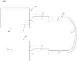
- FIG. 1is a schematic structural diagram of a fiber-to-the-home network provided by an embodiment of the present application
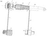
- FIG. 2is a schematic structural diagram of an optical fiber connection assembly provided by an embodiment of the present application.
- FIG. 3is a schematic exploded view of the adapter shown in FIG. 2;
- FIG. 4is a schematic structural view of the protective cap shown in FIG. 3;
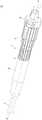
- FIG. 5is a schematic structural diagram of a prefabricated optical fiber provided by an embodiment of the present application.
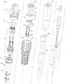
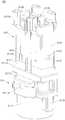
- FIG. 6is an exploded schematic view of the prefabricated optical fiber shown in FIG. 5;
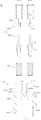
- FIG. 7is a schematic view of the three-dimensional structure of the spindle shown in FIG. 6;
- FIG. 8is a schematic diagram of the internal structure of the spindle shown in FIG. 7;
- FIG. 9Ais a schematic structural view of the connector shown in FIG. 6;
- FIG. 9Bis a schematic view of the assembly structure of the connector shown in FIG. 9A;
- FIG. 10is a schematic diagram of the internal structure of the connector shown in FIG. 9A;
- FIG. 11is a schematic diagram of the internal structure of the connector shown in FIG. 10 after assembly;
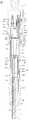
- FIG. 12is a cross-sectional view of the prefabricated optical fiber shown in FIG. 5 taken along line A-A;
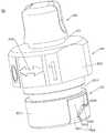
- FIG. 13is a schematic structural view of the locking cap shown in FIG. 6;
- FIG. 14is a schematic diagram of the internal structure of the locking cap shown in FIG. 13;
- FIG. 15is a schematic structural view of the dust cap shown in FIG. 6;
- FIG. 16is a schematic diagram of the internal structure of the sealing sleeve shown in FIG. 6;
- FIG. 17is a schematic diagram of the internal structure of the metal pressure ring shown in FIG. 6;
- FIG. 18is a schematic diagram of the internal structure of the tail sleeve shown in FIG. 6;
- FIG. 19is a schematic diagram of the internal structure of the snap ring shown in FIG. 6;
- FIG. 20is a schematic diagram of the internal structure of the rubber pot shown in FIG. 6.
- FIG. 1is a schematic structural diagram of a fiber-to-the-home network 100 provided by an embodiment of the present application.
- the fiber-to-the-home (FTTH) network 100includes a fiber distribution box 10, a prefabricated fiber 20, and a user terminal box 30. Both the fiber distribution box 10 and the user terminal box 30 are optical fiber boxes.
- the fiber distribution box 10(also called an optical fiber distribution box) is an interface device for connecting a trunk optical cable and a distribution optical cable (hereinafter referred to as an optical cable) outdoors, in a corridor, or indoors.
- the fiber distribution box 10includes a box body 101 and an adapter 1 (also called an optical fiber adapter) mounted on the box body 101.
- the fiber distribution box 10can be connected to a plurality of user terminal boxes 30 through a plurality of prefabricated optical fibers 20.
- the prefabricated optical fiber 20includes an optical cable 2 and an optical fiber connector 3.
- An optical fiber connector 3is installed at both ends of each optical cable 2.
- the user terminal box 30includes a box body 301 and an adapter 1 mounted on the box body 301.
- the two optical fiber connectors 3 of the prefabricated optical fiber 20are respectively connected to the adapter 1 of the fiber distribution box 10 and the adapter 1 of the user terminal box 30.
- the fiber-to-the-home network 100uses the prefabricated optical fiber 20, in the process of laying the cable, only two optical fiber connectors 3 of the prefabricated optical fiber 20 need to be inserted into the adapters of the fiber distribution box 10 1 and the adapter 1 of the user terminal box 30 can complete the installation process, thus greatly reducing the difficulty of installation and reducing the time of on-site construction.
- FIG. 2is a schematic structural diagram of an optical fiber connection assembly 200 provided by an embodiment of the present application.
- the optical fiber connection assembly 200includes an optical fiber connector 3 and an adapter 1.
- the connection between the optical fiber connector 3 and the adapter 1is a detachable connection.
- the fiber connection assembly 200can be applied to the connection between the fiber distribution box 10 and the prefabricated optical fiber 20 in the fiber-to-the-home network 100, and can also be applied to the connection between the prefabricated optical fiber 20 and the user terminal box 30 in the fiber-to-the-home network 100.
- One end of the optical fiber connector 3has a connector 31, and the optical cable 2 is inserted into the optical fiber connector 3 from the other end of the optical fiber connector 3 and connected to the connector 31. When the connector 31 is inserted into the adapter 1, optical signals can be transmitted between the adapter 1 and the optical cable 2.
- FIG. 3is a schematic exploded view of the adapter 1 shown in FIG. 2.
- the adapter 1includes a lock nut 11, a connecting rope 12, a ceramic sleeve 13, an adapter body 14, a sealing ring 15 and a protective cap 16.
- the adapter body 14includes an input terminal 141 and an output terminal 142 remote from the input terminal 141.
- the adapter body 14has a through hole 143 extending from the input end 141 to the output end 142.
- the optical signalcan be input from the input terminal 141 of the adapter body 14 and output from the output terminal 142 through the through hole 143.
- the through hole 143accommodates the partial connector 31 of the optical fiber connector 3.
- the shape of the through hole 143is adapted to the shape of the connector 31 accommodated therein.
- the number of through holes 143may be one or more. When the number of through-holes 143 is plural, the plurality of through-holes 143 are spaced apart from each other.
- Each through hole 143is provided with a ceramic sleeve 13. The ceramic sleeve 13 is used for docking with the partial connector 31 of the optical fiber connector 3 to transmit optical signals.
- a locking groove 1412is provided on the outer side wall 1411 of the input end 141.
- the locking groove 1412extends along the circumferential direction of the input end 141 by a second angle, and the second angle is less than or equal to 90°.
- the outer side wall 1411 of the input end 141is a cylindrical surface.
- the circumferential direction of the input end 141is a direction perpendicular to and disposed around the central axis of the outer side wall 1411 of the input end 141.
- the second angleis the center angle of the locking groove 1412.
- the second anglemay be an angle of 30° to 90°, for example, 30°, 45°, 60°, 75°, or 90°.
- the locking groove 1412includes a sliding area 1413, a sliding area 1414, and a locking area 1415 that are sequentially connected.
- the sliding area 1414 and the engaging area 1415extend in the circumferential direction of the input end 141.
- the sliding area 1413communicates the sliding area 1414 to the end surface of the input end 141.
- the engaging area 1415is provided with an engaging surface 1416 facing away from the sliding area 1413. For example, if the direction of the sliding area 1414 toward the engaging area 1415 is the sliding direction, the direction of the engaging surface 1416 is opposite to the sliding direction.
- the number of the locking grooves 1412can be one, two, or more than three.
- the number of locking grooves 1412is two as an example for description.
- the two locking grooves 1412are opposite to each other.
- the two locking grooves 1412are symmetrically distributed in the center. That is, after one of the locking grooves 1412 rotates 180° about the central axis of the outer side wall 1411 of the input end 141, it overlaps with the other locking groove 1412.
- the number of the locking grooves 1412can be designed according to the size of the second angle, and the plurality of locking grooves 1412 can be designed to be spaced from each other. For example, when the second angle is less than 60°, the number of locking grooves 1412 may be three.
- the adapter body 14further includes a stop flange 144 between the input end 141 and the output end 142.
- the side of the stop flange 144 facing the input end 141is provided with an arrow alignment mark 1441.
- the arrow alignment mark 1441is used to indicate the connection state and the release state of other components and the adapter body 14.
- a screw connection 1422is provided on the outer side wall 1421 of the output end 142.
- the lock nut 11is screwed to the screw connection 1422.
- the lock nut 11is used to connect the box body of the optical fiber box (see 101 or 301 in FIG. 1).
- the lock nut 11may also be a connection component for realizing other connection methods, and the screw connection portion 1422 is another structure corresponding to the connection component.
- Other connection methodsinclude but are not limited to snap connection, tenon-mortise connection, interference connection, elastic connection and other connection methods.
- FIG. 4is a schematic structural diagram of the protective cap 16 shown in FIG. 3.
- one end 121 of the connecting rope 12is sleeved on the outside of the adapter body 14, and the other end 122 of the connecting rope 12 is connected to the protective cap 16.
- one end 121 of the connecting rope 12is sleeved outside the output end 142 and is located between the stop flange 144 and the lock nut 11.
- the protective cap 16includes a connection cap portion 161 and a grip portion 162.
- the top of the connection cap portion 161is open.
- the grip portion 162is located at the bottom of the connection cap portion 161.
- a connection groove 163is provided between the connection cap portion 161 and the grip portion 162.
- the connection groove 163is a continuous annular groove.
- the end 122 of the connecting cord 12 away from the adapter body 14is located in the connecting groove 163 to connect the protective cap 16.
- the inner end of the protective cap 16is provided with a protective locking protrusion 164.
- One end of the protective cap 16can be sleeved on the outside of the input end 141, and the protective locking protrusion 164 is engaged with the locking groove 1412.
- the protective locking protrusion 164is provided inside the connecting cap portion 161.
- the protective locking projection 164slides from the sliding area 1413 into the locking groove 1412, and when the protective cap 16 rotates relative to the adapter body 14, after sliding to the engaging area 1415 through the sliding area 1414, it engages with the engaging area 1415
- the faces 1416snap together.
- the protective locking protrusion 164may also be provided with a buckling mating surface that cooperates with the buckling surface 1416 to increase the buckling stability of the protective locking protrusion 164 and the adapter body 14.
- the protective cap 16 and the adapter body 14are connected by a rotating snap lock.
- the rotation angle of the protective cap 16 relative to the adapter body 14is less than or equal to the second Angle, the second angle is less than or equal to 90°, so the installation and removal of the protective cap 16 is simple and takes a short time, and the snap connection between the protective cap 16 and the adapter body 14 has high stability and is not easy to loosen.
- the protective cap 16can Effectively protecting the adapter body 14 against water, dust, etc., is beneficial to improve the reliability of the adapter 1. Since the protective cap 16 is connected to the adapter body 14 through the connection cord 12, the protective cap 16 is not easy to detach, making the adapter 1 more reliable.
- An arrow indicator 1612may be provided on the outer side wall of the connecting cap portion 161 to guide the user's installation and removal actions.
- the outer side wall 1411 of the input end 141is provided with an arrow mark 1417 indicating the insertion direction.
- the protective cap 16can align the adapter body 14 so that it can be quickly mounted to the adapter body 14.
- the arrow indicator 1612 and the arrow alignment indicator 1441 of the stop flange 144cooperate, it can indicate the connection state or the release state of the protective cap 16 and the adapter body 14.
- a sealing groove 1418is provided on the outer side wall 1411 of the input end 141.
- the sealing groove 1418is an annular groove.
- the sealing groove 1418is located on the side of the locking groove 1412 near the output end 142.
- the sealing ring 15is installed in the sealing groove 1418.
- FIG. 5is a schematic structural diagram of a prefabricated optical fiber 20 provided by an embodiment of the present application.
- FIG. 6is an exploded schematic diagram of the prefabricated optical fiber 20 shown in FIG. 5.
- the optical fiber connector 3 of the prefabricated optical fiber 20 shown in FIG. 5corresponds to the optical fiber connector 3 shown in FIG. 2. Among them, some structures of the cord 37 of the optical fiber connector 3 in FIGS. 5 and 6 are not shown.
- the prefabricated optical fiber 20includes an optical cable 2 and an optical fiber connector 3.
- the optical fiber connector 3includes a dust cap 32, a first sealing ring 33, a connecting member 31, a main shaft 34, an elastic member 35, a second sealing ring 36, a strap 37, a snap ring 38, a rubber sleeve 310, and a locking cap 39 , Tail sleeve 320, metal pressure ring 330 and sealing sleeve 340.
- the locking cap 39, one end 371 of the strap 37 and the tail sleeve 320are arranged in the axial direction of the optical fiber connector 3 (parallel to the line A-A in FIG. 5).
- the locking cap 39is a hollow cylinder (also referred to as a sleeve, that is, the cylinder has an inner through-hole structure penetrating from one end to the other end).
- the tail sleeve 320is a hollow cylinder.
- the inner through hole 395 of the locking cap 39communicates with the inner through hole of the tail sleeve 320.
- the connecting member 31is partially located in the inner through hole 395 of the locking cap 39, and the connecting member 31 is partially protruding from the end of the locking cap 39 away from the tail sleeve 320.
- the optical cable 2 of the prefabricated optical fiber 20can extend from the end of the tail sleeve 320 away from the locking cap 39, extend into the inner through hole of the tail sleeve 320 and the inner through hole 395 of the locking cap 39 in sequence, and be connected to the connector 31.
- Other structures of the optical fiber connector 3are located in the inner through hole 395 of the locking cap 39 and the inner through hole of the tail sleeve 320.
- the dust cap 32is connected to the other end 372 of the strap 37.
- the strap 37can be bent.
- the dust cap 32can be installed on the end of the locking cap 39 away from the tail sleeve 320 to be sleeved on the outside of the connector 31, thereby achieving waterproof and dustproof And the protection of the connecting member 31.
- FIG. 2when the optical fiber connector 3 is to be connected to the adapter 1, the dust cap 32 is detached from the locking cap 39 so that the connector 31 is exposed to insert the adapter 1. However, the dust cap 32 is still connected to other structures of the optical fiber connector 3 through the strap 37, so as to avoid the loss of the dust cap 32.
- the dust cap 32can be installed again to be locked after the optical fiber connector 3 is removed from the adapter 1 Cap 39, so that the optical fiber connector 3 allows frequent insertion and removal work, and the reliability of the optical fiber connector 3 is higher.
- FIG. 7is a schematic perspective view of the main shaft 34 shown in FIG. 6.
- FIG. 8is a schematic internal structure of the main shaft 34 shown in FIG. 7.
- the main shaft 34includes a head end 341 and an end 342 away from the head end 341.
- the main shaft 34also includes a transition section 343 between the head end 341 and the end 342.
- the first end 341, the transition section 343 and the end 342are arranged in this order.
- the main shaft 34is a hollow cylinder.
- the main shaft 34has a through hole 344 extending from the head end 341 to the end 342.
- the through hole 344is the inner through hole of the main shaft 34.
- the inner diameter of the head end 341is larger than the inner diameter of the transition section 343.
- the inner diameter of the transition section 343is larger than the inner diameter of the tip 342.
- the through hole 344is a variable diameter hole.
- the main shaft 34has a substantially circular hollow cylindrical structure. In other embodiments, the through hole 344 may also be a through hole of another shape.
- Two lugs 345are provided on the top of the head end 341 away from the transition section 343.
- the two lugs 345are arranged oppositely.
- the top of each lug 345 away from the transition section 343is provided with a limiting block 3451.
- the two limiting blocks 3451 of the two lugs 345are bent toward each other.
- One of the lugs 345is provided with a first positioning hole 3452.
- the outer side wall 3411 of the first end 341is further provided with a limiting protrusion 3412 and a limiting protrusion 3413.
- the limiting convex point 3412 and the limiting convex edge 3413are opposite to each other.
- the limiting convex point 3412 and the limiting convex edge 3413may be respectively disposed near the two lugs 345.
- the first end 341is also provided with a plug slot 3414.
- the insertion groove 3414communicates the through hole 344 to the outside of the main shaft 34.
- the insertion slot 3414extends to the top of the head end 341.
- a sealing groove 346 surrounding the through hole 344is provided on the outer circumferential side of the main shaft 34.
- the sealing groove 346is a continuous annular groove.
- the sealing groove 346is located partly at the head end 341 and partly at the transition section 343. In other embodiments, the sealing groove 346 may also be completely located at the head end 341 or completely located at the transition section 343.
- the transition section 343has a first limiting surface 3431 facing the end 342.
- the first limiting surface 3431is located on the side of the sealing groove 346 near the end 342.
- the first limiting surface 3431is located on the outer side wall of the transition section 343.
- the tip 342includes a rubber portion 3421 near the head end 341 and a metal portion 3422 away from the head end 341.
- the metal portion 3422is partially located inside the rubber portion 3421, and the rubber portion 3421 is fixedly connected.
- the metal portion 3422 and the rubber portion 3421can be integrally formed by in-mold injection (IMD).
- IMDin-mold injection
- the metal portion 3422 and the rubber portion 3421can also be formed into an integrated structure by an assembly method (for example, screw connection or snap connection).
- the outer peripheral side of the tip 342is further provided with a limiting groove 3423 surrounding the through hole 344.
- the limiting groove 3423is located in the rubber portion 3421.
- the limiting groove 3423is a continuous annular groove.
- FIG. 9Ais a schematic structural view of the connector 31 shown in FIG. 6,
- FIG. 9Bis a schematic structural diagram of the assembly of the connector 31 shown in FIG. 9A
- FIG. 10is a connection shown in FIG. 9A
- FIG. 11is a schematic diagram of the internal structure of the connector 31 shown in FIG. 10 after being assembled.
- the connector 31is a small rectangular optical fiber connector (Lucent Connector, LC) as an example for description.
- the connector 31may also be a square connector (SC), a small unit coupling type (miniature unit coupling) (MU), or a multi-fiber push connector (MPO) .
- SCsmall rectangular optical fiber connector
- MUsmall unit coupling type
- MPOmulti-fiber push connector
- the connector 31includes a connection base 311 and one or more connection terminals 312. One or more connection terminals 312 are mounted on the connection base 311.
- the connecting member 31further includes a connecting elastic member 313.
- the number of connection elastic members 313is the same as the number of connection terminals 312. In this embodiment, the number of connecting terminals 312 is two as an example for description, and the number of connecting elastic members 313 is also two.
- connection base 311can be installed with one or more connection terminals 312 at the same time, the optical fiber connector 3 can be applied to more prefabricated optical fibers 20 with different requirements, and the applicability of the optical fiber connector 3 is better .
- connection base 311is installed with a plurality of connection terminals 312 at the same time, the port density of the optical fiber connector 3 is high.
- the connection base 311includes a fixing portion 3111 and one or more mounting portions 3112 located on the side of the fixing portion 3111.
- the fixing portion 3111 and one or more mounting portions 3112are integrally formed. That is, the connection base 311 is integrally formed.
- the number of mounting portions 3112is the same as the number of connection terminal 312 pairs. When the number of the mounting parts 3112 is plural, the plural mounting parts 3112 are located on the same side of the fixing part 3111.
- the one or more mounting portions 3112are partially inserted into the one or more connection terminals 312 in a one-to-one correspondence. At this time, the one or more connection terminals 312 are fixed to the connection base 311 by a plug-in method.
- the optical fiber connector 3is inserted into the connection terminal 312 through the mounting portion 3112 to realize the fixing of the connection terminal 312 and the connection base 311, so that the connection base 311 can be an integrally formed structure to reduce the production of the connection base 311 Cost and production difficulty.
- the assembly process of connecting the connection terminal 312 and the connection base 311 by pluggingis more convenient and the assembly difficulty is less.
- a communication structure 3113is formed inside the fixing portion 3111.
- Through holes 3114are formed inside each mounting portion 3112.
- the communication structure 3113includes an inlet and two outlets that communicate with the inlet.
- the through holes 3114 of the two mounting portions 3112communicate with the two outlets, respectively.
- the cable 21 (see FIG. 6) of the optical cable 2may extend into the through hole 3114 of the mounting portion 3112 through the communication structure 3113 of the fixing portion 3111.
- the fixing part 3111has a positioning plane 31112 facing one or more mounting parts 3112.
- the connecting base 311 of the connecting member 31is mounted to the main shaft 34 (see FIG. 7 )
- the two limiting blocks 3451 on the two lugs 345 of the head end 341 of the main shaft 34are engaged on the positioning plane 31112 to make the connecting member 31 is fixed relative to the main shaft 34 to prevent the connecting member 31 from being separated from the main shaft 34.
- a plug block 3115is formed on the outer side wall of the fixing portion 3111.
- the fixing part 3111also has a limit plane 3116 facing away from the one or more mounting parts 3112.
- the limit plane 3116is a part of the outer side wall of the fixing portion 3111.
- the outer peripheral side of the fixing portion 3111further has a second positioning hole 31114.
- the fixing portion 3111has a fixing end surface 31113 facing one or more mounting portions 3112.
- the one or more mounting portions 3112extend from the fixing end surface 31113 in a direction away from the fixing portion 3111.
- Each mounting portion 3112has a mounting bottom 3117 and a mounting top 3118.
- the mounting bottom 3117is fixed to the fixed end surface 31113.
- the mounting top 3118is connected to the top end surface of the mounting bottom 3117 away from the fixed end surface 31113.
- the mounting portion 3112is provided with a limiting protrusion 3119.
- the mounting top 3118has two limit bumps 3119 disposed opposite to each other.
- the mounting portion 3112also has a positioning block 31110 located between the two limiting protrusions 3119.
- the second positioning hole 31114 and the two limiting protrusions 3119are located on the outer side wall of the mounting top 3118.
- the projection of the outer side wall of the mounting top 3118 on the top surface of the mounting bottom 3117falls within the range of the top surface.
- Each mounting portion 3112has an abutment surface 31111 facing away from the fixing portion 3111 inside.
- the resisting surface 31111is an annular surface provided around the inner through hole of the mounting portion 3112.
- each connection terminal 312includes a protective shell 3121 and a ferrule 3122 installed inside the protective shell 3121.
- the protective shell 3121has a substantially hollow square pillar structure.
- the protective shell 3121is provided with a limiting hole 3123.
- the protective shell 3121is provided with two limiting holes 3123 disposed oppositely.
- the limiting hole 3123communicates with the inner through hole of the protective shell 3121.
- the mounting portion 3112is partially inserted into the corresponding protective shell 3121, and the limiting protrusion 3119 is partially or fully engaged into the limiting hole 3123.
- the matching structure of the limiting protrusion 3119 and the limiting hole 3123can fix the connection terminal 312 relative to the connection base 311.
- connection terminal 312 and the connection base 311are fixed to each other by the snap connection between the limit hole 3123 and the limit protrusion 3119, so the connection terminal 312 and the connection base 311 can be realized Plug and fix, the connection between the two is easy to achieve, and the stability is good.
- the protective shell 3121is further provided with a positioning slot 3124 between the two limiting holes 3123.
- Two limiting holes 3123 and positioning slots 3124are respectively located on the three side walls of the protective shell 3121.
- the positioning slot 3124extends to the bottom end surface of the protective shell 3121 facing the fixing portion 3111.
- the positioning slot 3124is used to receive the positioning block 31110.
- the inner surface of the protective shell 3121includes a first positioning surface 3125 facing the fixing portion 3111.
- the inner surfaceis the hole wall of the inner through hole of the protective shell 3121.
- the first positioning surface 3125faces the bottom end surface of the protective shell 3121.
- the ferrule 3122is a hollow cylindrical structure.
- the ferrule 3122has a bottom part close to the fixing part 3111 and a top part far away from the fixing part 3111.
- the outer side wall of the ferrule 3122includes a second positioning surface 3126 facing away from the fixing portion 3111.
- the second positioning surface 3126faces the top of the ferrule 3122.
- the outer side wall of the ferrule 3122further includes a bearing surface 3127 facing the fixing portion 3111.
- the resisting surface 3127is opposite to the second positioning surface 3126.
- the connecting elastic member 313is compressed between the ferrule 3122 and the mounting portion 3112, and the elastic force of the connecting elastic member 313 presses the second positioning surface 3126 against the first positioning surface 3125.
- one end of the connecting elastic member 313is located between the ferrule 3122 and the protective shell 3121 body and resists the resisting surface 3127 of the ferrule 3122.
- the other end of the connecting elastic member 313is located inside the mounting portion 3112 and abuts the abutting surface 3111 of the mounting portion 3112.
- the ferrule 3122is fixed relative to the protective shell 3121, and the ferrule 3122 is not easy to shake, which is beneficial to ensure the connection reliability when the optical fiber connector 3 is connected to the adapter 1.
- the top surface 3128 of the protective shell 3121 away from the connection base 311protrudes from the top surface 3129 of the ferrule 3122 away from the connection base 311.
- the front end surface 3128 of the protective shell 3121can protect the ferrule 3122.
- one or more protective protrusions 31210are provided on the top of the protective shell 3121.
- the end surface of the one or more protection protrusions 31210 away from the baseis the top surface 3128 of the protection shell 3121.
- the top of the protective shell 3121is further provided with two protective bumps 31210 opposite to each other.
- the two protection protrusions 31210are located on both sides of the inner through hole of the protection shell 3121 respectively.
- the two protective protrusions 31210are respectively connected to two opposite side walls of the protective shell 3121.
- FIG. 12is a cross-sectional view of the prefabricated optical fiber 20 shown in FIG. 5 taken along line A-A.
- connectionrefers to that the relative positional relationship between the two components after assembly is kept fixed, and the two components may be detachable connections or non-detachable connections.
- connection base 311 of the connector 31is inserted into the through hole 344, and one or more connection terminals 312 are fixed to the other end of the connection base 311.
- the limiting plane 3116 of the connecting base 311abuts against the top end surface of the main shaft 34 (that is, the top end surface of the head end 341 facing away from the end 342 ). At this time, the connector 31 and the main shaft 34 realize the positioning of the optical fiber connector 31 in the axial direction of each other. Referring to FIG.
- the second positioning hole 31114 of the fixing portion 3111 of the connector 31is aligned with the first positioning hole 3452 of the lug 345 of the main shaft 34, and can be inserted into the first positioning hole 3452 and the second positioning hole 31114 through the latch 350, thereby
- the connector 31 and the main shaft 34are positioned in the axial direction and the circumferential direction of the optical fiber connector 31 (the direction perpendicular to and surrounding the axial direction of the optical fiber connector 31 ).
- the plug block 3115(see FIGS. 9A and 9B) of the connecting member 31 connected to the base 311 is inserted into the plug groove 3414 (see FIG. 7) of the head end 341 of the main shaft 34.
- the plug block 3115cooperates with the plug groove 3414 to position the main shaft 34 and the connector 31 in the circumferential direction of the optical fiber connector 31.
- FIG. 13is a schematic structural view of the locking cap 39 shown in FIG. 6, and FIG. 14 is a schematic structural view of the locking cap 39 shown in FIG. 13.
- the locking cap 39is a hollow cylinder.
- the locking cap 39is sleeved on the outside of the main shaft 34 and the connecting member 31.
- the lock cap 39includes a sealing portion 391 and a connecting portion 392 connected to one side of the sealing portion 391.
- the locking cap 39further includes a limiting portion 393 connected to the side of the sealing portion 391 away from the connecting portion 392.
- the connecting portion 392, the sealing portion 391 and the limiting portion 393are arranged in this order in the axial direction of the optical fiber connector 3.
- the inner through hole 395 of the locking cap 39penetrates from the end of the connecting portion 392 to the end of the limiting portion 393.
- the sealing portion 391is rotatably connected to the outside of the head end 341 of the main shaft 34.
- the connecting portion 392is located on the side of the first end 341 away from the end 342.
- the connecting portion 392surrounds the outside of the connecting member 31.
- the limiting portion 393is located outside the transition section 343. 2, when the optical fiber connector 3 is connected to the adapter 1, the connector 31 is partially inserted into the input end 141 of the adapter body 14, and the input end 141 of the adapter body 14 is inserted into the connecting portion 392 inside the locking cap 39.
- the connecting portion 392is used to partially accommodate the adapter 1 when the connector 31 is inserted into the adapter 1.
- the inner diameter of the connecting portion 392is larger than the inner diameter of the sealing portion 391.
- the inner diameter of the sealing portion 391is larger than the inner diameter of the stop portion 393.
- the inner through hole 395 of the locking cap 39is a reducing hole.
- the inner through hole 395 of the locking cap 39may also be a through hole of other shapes.
- the outer diameter D1 of the sealing portion 391is smaller than the outer diameter D2 of the connecting portion 392.
- the outer diameter D3 of the limiting portion 393may be smaller than the outer diameter D1 of the sealing portion 391. That is, the outer diameter D2 of the connecting portion 392, the outer diameter D1 of the sealing portion 391, and the outer diameter D3 of the stop portion 393 are sequentially reduced.
- the outer surface of the locking cap 39has a stepped structure to meet the accommodation requirements of the locking cap 39 (most components of the optical fiber connector 3 need to be accommodated inside the locking cap 39), and the volume of the locking cap 39 is reduced as much as possible, so that The optical fiber connector 3 is more compact.
- a locking protrusion 394is provided inside the connecting portion 392.
- the locking protrusion 394is located on the hole wall of the inner through hole 395 of the locking cap 39.
- the number of locking protrusions 394is two.
- the two locking protrusions 394are oppositely arranged. In other embodiments, the number of the locking protrusions 394 may be one or more than three.
- the locking protrusion 394is used to engage with the locking groove 1412 of the adapter 1 when the locking cap 39 rotates at a first angle relative to the adapter 1.
- the first angleis less than or equal to 90°.
- the connecting portion 392partially receives the input end 141 of the adapter body 14, and the locking protrusion 394 is located in the locking groove 1412
- the locking protrusion 394engages with the locking groove 1412, the first angle is less than or equal to the second angle.
- the locking protrusion 394slides from the sliding area 1413 into the locking groove 1412, and when the locking cap 39 rotates relative to the adapter body 14, after sliding to the engaging area 1415 through the sliding area 1414, it engages with the engaging area 1415
- the faces 1416snap together. That is, the through hole 143 of the adapter body 14 can be used to receive the partial connector 31 of the optical fiber connector 3 when the input end 141 is inserted into the locking cap 39 of the optical fiber connector 3.
- the locking groove 1412 of the adapter body 14is used to receive the locking protrusion 394 inside the locking cap 39 and engage with the locking protrusion 394.
- the locking groove 1412extends a second angle along the circumference of the input end 141 of the adapter body 14, so The first angle is less than or equal to the second angle. Since the locking cap 39 and the adapter body 14 are connected by a rotation and locking method, the first angle can be set or changed through the structural design of the locking groove 1412, so that the locking cap 39 can be connected to the adapter body The angle of rotation required at 14 o'clock.
- the rotation angle of the locking cap 39 relative to the adapter body 14is less than or equal to the second angle, and the second angle is less than or equal to 90
- the locking cap 39only needs to rotate an angle of less than a quarter turn relative to the adapter body 14 to complete the installation or removal of the optical fiber connector 3 and the adapter 1, so the installation and removal of the optical fiber connection assembly 200 is simple 3.
- Short timeapproximately one-fifth or even shorter than that of the traditional fiber connection assembly
- the signal of the fiber connection assembly 200High transmission reliability.
- connection terminal 312(see FIG. 9B) of the optical fiber connector 3 of this embodiment is no longer provided with a traditional elastic arm, and the locking requirement between the optical fiber connector 3 and the adapter 1 is realized by a rotating snap lock structure Therefore, the traditional two-step disassembly and assembly process (removal of the elastic arm and disassembly of the protective cover) is reduced to a one-step disassembly and assembly process, which further reduces the difficulty and time of disassembly and assembly of the optical fiber connector 3 and the adapter 1.
- the connection terminal 312since the connection terminal 312 is no longer provided with an elastic arm structure, the volume of the connection terminal 312 is reduced, so that the port density can be increased without sacrificing the volume of the optical fiber connector 3.
- the locking protrusion 394may also be provided with a snap-fitting surface that cooperates with the snap-fit surface 1416 to increase the locking stability of the locking protrusion 394 and the adapter body 14. It can be understood that the structure of the locking protrusion 394 is matched with the structure of the locking groove 1412, and the locking connection structure of the locking cap 39 and the adapter body 14 is locked and the protective cap 16 of the adapter 1 and the adapter body The connection structure of the 14 rotation lock is the same.
- the outer side wall 3921 of the connecting portion 392is provided with an arrow indicator 3922.
- the locking cap 39can align the adapter body 14 so that the adapter body 14 can be quickly installed.
- the arrow indicator 3922cooperates with the arrow alignment indicator 1441 of the stop flange 144 of the adapter body 14 to indicate the connection or release state of the locking cap 39 and the adapter body 14.
- the outer wall 3921 of the connecting portion 392 and the outer wall 3911 of the sealing portion 391are both provided with shallow grooves.
- the shallow groove 3923 of the connecting portion 392communicates with the shallow groove 3912 of the sealing portion 391, and both of them continuously extend in the axial direction of the locking cap 39 (that is, in the axial direction of the optical fiber connector 3).
- the shallow groove 3923 of the connecting portion 392 and the shallow groove 3912 of the sealing portion 391may have other shapes and other connection relationships.
- the outer side wall of the limiting portion 393includes a plurality of flat planes 3931 disposed symmetrically. The number of flat surfaces 3931 is four. The two opposite flattened planes 3931 form a set of flattened planes 3931. Each flattened plane 3931 is provided with a shallow groove 3932.
- the shallow trench 3932may extend in a direction perpendicular to the axial direction. At this time, the user feels better when holding or operating the locking cap 39 and is less likely to slide.
- the sealing portion 391has a stop surface 3913 facing the connecting portion 392.
- the stop surface 3913is a part of the hole wall of the inner through hole 395 of the locking cap 39.
- the limiting portion 393has a second limiting surface 3924 facing the sealing portion 391.
- the second limiting surface 3924may be a part of the end surface of the limiting portion 393 connected to the sealing portion 391.
- the second limiting surface 3924is a part of the hole wall of the inner through hole 395 of the locking cap 39.
- the optical fiber connector 3further includes an elastic member 35.
- the elastic member 35is located between the transition section 343 and the sealing portion 391, and both ends of the elastic member 35 abut against the first limiting surface 3431 and the second limiting surface 3924, respectively.
- the first limiting surface 3431 and the second limiting surface 3924have a tendency to move away from each other, and the locking cap 39 has a tendency to move closer to the end 342 of the main shaft 34, so when the locking cap 39 is connected to the adapter 1 (see FIG. 3 ), the locking protrusion 394 can stably engage the locking groove 1412 of the adapter body 14, and the connecting member 31 and the adapter body 14 are in the axial direction of the optical fiber connector 3 Fixing each other makes the connection relationship between the locking cap 39 and the adapter 1 reliable, and the effect of shockproof and loosening is good.
- FIG. 15is a schematic structural view of the dust cap 32 shown in FIG. 6.
- one end 371 of the cord 37 of the optical fiber connector 3is sleeved on the outside of the main shaft 34, and the other end 372 of the cord 37 is connected to the dust cap 32.
- the dust cap 32includes an insertion portion 321 and a grip portion 322. The top side of the insertion portion 321 is opened. The grip portion 322 is connected to the bottom side of the insertion portion 321.
- a connection groove 323is provided between the insertion portion 321 and the grip portion 322.
- the connection groove 323is a continuous annular groove.
- An end 372 of the cord 37 away from the main shaft 34is located in the connecting groove 323 to connect the dust cap 32.
- one end of the dust cap 32is provided with a dust locking groove 324.
- One end of the dust cap 32can extend into the inner side of the connecting portion 392, and the dust locking groove 324 is engaged with the locking protrusion 394.
- the outer wall 3211 of the insertion portion 321is provided with a dust-proof locking groove 324.
- the dust-proof locking groove 324extends at a third angle along the circumferential direction of the insertion portion 321. The third angle may be less than or equal to 90°.
- the outer wall 3211 of the insertion portion 321is a cylindrical surface.
- the circumferential direction of the insertion portion 321is a direction that is perpendicular to and surrounds the central axis of the outer side wall 3211 of the insertion portion 321.
- the third angleis the center angle of the dustproof locking groove 324.
- the third anglemay be an angle of 30° to 90°, for example, 30°, 45°, 60°, 75°, or 90°.
- the dust-proof locking groove 324includes a sliding area 3241, a sliding area 3242, and a locking area 3242 which are sequentially connected.
- the sliding area 3242 and the engaging area 3243extend in the circumferential direction of the insertion portion 321.
- the sliding area 3241communicates the sliding area 3242 to the end surface of the insertion portion 321.
- the engaging area 3243is provided with an engaging surface 3244 that slides back into the area 3242. For example, if the direction of the sliding region 3242 toward the engaging region 3243 is the sliding-in direction, the direction of the engaging surface 3244 is opposite to the sliding-in direction.
- the insertion portion 321 of the dust cap 32is fully inserted or partially extended into the inner side of the connecting portion 392 of the locking cap 39.
- the connector 31partially extends into the inside of the insertion portion 321.
- the locking protrusion 394 of the locking cap 39slides from the sliding-in area 3241 into the dust locking groove 324, and when the dust cap 32 rotates relative to the locking cap 39 (or the locking cap 39 rotates relative to the dust cap 32) After sliding to the engaging area 3243 through the sliding area 3242, it engages with the engaging surface 3244 of the engaging area 3243.
- the locking protrusion 394 of the locking cap 39also has a snap-fitting surface that cooperates with the snap-fit surface 3244 to increase the locking stability between the locking protrusion 394 and the dust-proof locking cap 39.
- the locking cap 39 of the optical fiber connector 3 of the optical fiber connection assembly 200 and the adapter body 14 of the adapter 1are connected by a rotating snap lock structure, and the locking cap of the optical fiber connector 3 39 and the dust cap 32 of the optical fiber connector 3 are also connected by a rotary snap lock structure, and the protective cap 16 of the adapter 1 and the adapter body 14 are also connected by a rotary snap lock structure, so the protective cap 16 of the adapter 1 Is similar to the connection structure of the locking cap 39 of the optical fiber connector 3, and the connection structure of the dust cap 32 of the optical fiber connector 3 is similar to the connection structure of the adapter body 14 of the adapter 1.
- connection between the optical fiber connector 3 and the adapter 1the connection between the internal components of the optical fiber connector 3 and the connection between the internal components of the adapter 1 are achieved by the same rotation locking structure
- the structure of the optical fiber connection assembly 200is more simplified, and the installation operation is more difficult.
- the third angleis equal to the second angle, so that the connecting action of the dust cap 32 and the locking cap 39 is the same as the connecting action of the adapter body 14 and the locking cap 39, thereby improving the user experience.
- the number of the dustproof locking grooves 324may be one, two or more than three.
- the number of dust-proof locking grooves 324is two as an example for description.
- the two dust-proof locking grooves 324are opposite to each other.
- the two dustproof locking grooves 324are symmetrically distributed in the center. That is, after one of the dust-proof locking grooves 324 rotates 180° around the central axis of the outer side wall 3211 of the insertion portion 321, it overlaps the other dust-proof locking grooves 324.
- the number of the dust-proof locking grooves 324can be designed according to the size of the second angle, and the plurality of dust-proof locking grooves 324 can be designed to be spaced apart from each other. For example, when the second angle is less than 60°, the number of dustproof locking grooves 324 may be three.
- the dust cap 32further includes an intermediate portion 325 between the insertion portion 321 and the grip portion 322.
- the outer side wall 3251 of the middle portion 325is provided with an arrow alignment mark 3252.
- the arrow alignment mark 3252is used to indicate the connection state and the release state of the other components and the dust cap 32.
- the first sealing ring 33 of the optical fiber connector 3is located inside the connecting portion 392.
- the first seal ring 33is compressed between the connection portion 392 and the dust cap 32.
- the outer wall 3211 of the insertion portion 321 of the dust cap 32is provided with a sealing connection groove 3212.
- the sealing connection groove 3212is located between the middle portion 325 and the dust-proof locking groove 324.
- the first seal ring 33is installed in the seal connection groove 3212.
- the first sealing ring 33is used to be compressed between the connection portion 392 and the adapter 1. At this time, the sealing ring 15 of the adapter 1 is separated from the sealing groove 1418. The first sealing ring 33 is installed in the sealing groove 1418.
- the first sealing ring 33is used to achieve sealing when the locking cap 39 is connected to other components, so as to achieve waterproof and dustproof effects.
- the optical fiber connector 3can achieve IP68 protection level, so that the optical fiber connector 3 Longer service life and higher reliability.
- the second sealing ring 36 of the optical fiber connector 3is compressed between the groove wall of the sealing groove 346 and the inner side of the sealing portion 391.
- the inner surface of the sealing portion 391is a part of the hole wall of the inner through hole 395 of the lock cap 39.
- the second sealing ring 36can prevent the gap between the self-locking cap 39 and the main shaft 34 from entering the inside of the locking cap 39 by external moisture, dust, etc., and the optical fiber connector 3 can reach the IP68 protection level to improve the optical fiber connector 3 Reliability.
- FIG. 16is a schematic diagram of the internal structure of the sealing sleeve 340 shown in FIG. 6.
- One end 3401 of the sealing sleeve 340 of the optical fiber connector 3is sealingly sleeved outside the end 342 of the main shaft 34.
- the other end 3402 of the sealing sleeve 340is used to allow the optical cable 2 to be inserted and hermetically connect the optical cable 2.
- the sealing sleeve 340is a hollow cylinder.
- the optical cable 2is inserted into the through hole 344 of the main shaft 34 after passing through the inner through hole of the sealing sleeve 340.
- the sealing sleeve 340is used to achieve a sealed connection between the optical cable 2 and the main shaft 34, thereby improving the reliability of the optical fiber connector 3 and extending the service life of the optical fiber connector 3.
- the sealing sleeve 340may be a heat shrinkable sleeve.
- the sealing sleeve 340may be a sleeve with glue on the inner surface, so as to improve the connection reliability with the end 342 of the main shaft 34 and the optical cable 2.
- the inner diameter of the end 3401 (the top end in FIG. 16) of the sealing sleeve 340 connected to the end 342 of the main shaft 34is larger than the inner diameter of the end 3402 (the bottom end in FIG. 16) of the optical cable 2.
- the size of the inner diameter of the middle portion 3403 between the two ends (3401/3402) of the sealing sleeve 340may be between the sizes of the inner diameters of the two ends (3401/3402).
- the inner through hole 3404 of the sealing sleeve 340may be a reducing hole.
- the outer side wall of the sealing sleeve 340is substantially stepped.
- the sealing sleeve 340seals and connects the partial metal portion 3422 and the partial rubber portion 3421. That is, the sealing sleeve 340 connects the one end 3401 of the end 342 of the main shaft 34, and seals the connecting portion 392 into the metal portion 3422 and the partial rubber portion 3421 at the same time. At this time, the connection relationship between the sealing sleeve 340 and the end 342 of the main shaft 34 is more stable and reliable.
- the optical cable 2 of the prefabricated optical fiber 20may include a cable 21, an aramid yarn 22, a cable sleeve 23, a first support ring 24, and a second support ring 25. Both the cable 21 and the aramid yarn 22 are located inside the cable cover 23.
- the aramid yarn 22may be wound around the cable 21. The tensile strength and bending strength of the aramid yarn 22 are greater than the cable 21.
- the aramid yarn 22is used to protect the cable 21 to reduce the risk of the cable 21 breaking and increase the tensile strength of the optical cable 2.
- the cable sleeve 23wraps the cable 21 and the aramid yarn 22 for protection.
- the first support ring 24is a metal ring.
- the first support ring 24surrounds the outer side of the cable 21 and the aramid yarn 22 and is located inside the cable cover 23.
- the second support ring 25is a metal ring.
- the second support ring 25surrounds the outer side of the cable 21 and the aramid yarn 22 and is located inside the cable cover 23.
- the second support ring 25 and the first support ring 24are spaced apart from each other. Both the second support ring 25 and the first support ring 24 play a supporting and protecting role.
- FIG. 17is a schematic diagram of the internal structure of the metal pressing ring 330 shown in FIG. 6.
- the metal pressure ring 330 of the optical fiber connector 31is located inside the sealing sleeve 340.
- the metal pressure ring 330is a hollow body.
- One end 3301 of the metal pressure ring 330is sleeved outside the metal portion 3422 of the end 342 of the main shaft 34.
- the other end 3302 of the metal pressing ring 330is used to sleeve around the outer side of the optical cable 2, and the one end 3301 of the metal pressing ring 330 can press the aramid yarn 22 of the optical cable 2 against the metal portion 3422.
- the metal pressure ring 330presses the aramid yarn 22 against the metal portion 3422, which improves the connection strength of the optical cable 2 and the main shaft 34, and makes the tensile strength of the optical fiber connector 3 higher.
- the inner diameter of one end 3301 (the top end in FIG. 17) of the metal pressing ring 330 connected to the metal portion 3422is larger than the inner diameter of the other end 3302 (the bottom end in FIG. 17 ).
- the inner through hole 3303 of the metal pressure ring 330is a variable diameter hole.
- the outer side wall of the metal pressure ring 330is stepped.
- FIG. 18is a schematic diagram of the internal structure of the tail sleeve 320 shown in FIG. 6.
- the tail sleeve 320is a hollow cylinder.
- the tail sleeve 320is sleeved on the outer end of the end 342 of the main shaft 34 and the sealing sleeve 340.
- the tail sleeve 320is hermetically connected to the end 342 of the main shaft 34.
- the tail sleeve 320is hermetically connected to the sealing sleeve 340.
- the tail sleeve 320may be a formed sleeve member, which is sleeved on the outer end of the end 342 of the main shaft 34 and the sealing sleeve 340 by assembly.
- the tail sleeve 320may be directly formed on the outer end of the end 342 of the main shaft 34 and the sealing sleeve 340 by injection molding.
- the tail sleeve 320can play a role of protection and sealing to increase the tensile strength and sealability of the optical fiber connector 3.
- the shape and size of the inner through-hole 3201 of the tail sleeve 320are adapted to the end 342 of the main shaft 34 and the sealing sleeve 340, and the tail sleeve 320 tightly wraps the end 342 of the main shaft 34 and the sealing sleeve 340.
- end sleeve 320is sleeved on one end of the end 342 of the main shaft 34 and is provided with an inner snap protrusion 3202.
- the inner snap protrusion 3202extends into the inner through hole 3201 of the tail sleeve 320.
- FIG. 19is a schematic diagram of the internal structure of the snap ring 38 shown in FIG. 6.
- the optical fiber connector 3also includes a snap ring 38.
- the snap ring 38is installed in the limit groove 3423 of the end 342 of the main shaft 34 (see FIG. 7 ).
- the snap ring 38is fixed relative to the main shaft 34.
- the outer wall of the snap ring 38forms a stepped structure.
- the outer side wall of the snap ring 38has a stepped surface 381.
- the step surface 381faces the transition section 343 of the main shaft 34.
- the inner buckle of the tail sleeve 320abuts the step surface 381 along the edge 3202.
- the tail sleeve 320may be further fixed relative to the main shaft 34 by the snap ring 38 to reduce the risk that the tail sleeve 320 accidentally detaches from the main shaft 34, so that the tensile strength of the optical fiber connector 3 is higher.
- FIG. 20is a schematic diagram of the internal structure of the rubber pouring sleeve 310 shown in FIG. 6.
- the rubber injection sleeve 310is located inside the main shaft 34.
- the rubber pouring sleeve 310includes a main body 3101 and at least two support parts 3102 fixed inside the main body 3101. At least two support portions 3102 are arranged at intervals in the axial direction of the main body portion 3101.
- the cable 21 of the optical cable 2may extend into the inside of the main body portion 3101 and be laid or passed through at least two support portions 3102 in sequence.
- the encapsulating sleeve 310is used to support and fix the portion of the cable 21 located in the through hole 344 of the main shaft 34 to fix the cable 21 relative to the main shaft 34 and avoid damage to the cable 21 due to frequent shaking or impact, so that The reliability of the optical fiber connector 3 is higher.
- the main body portion 3101is provided with a third positioning hole 3103.
- the spindle 34is provided with a corresponding fourth positioning hole 3104 (see FIG. 6).
- the fourth positioning hole 3104is provided in the transition section 343 of the main shaft 34.
- the positioning holes of the fourth positioning hole 3104 and the third positioning hole 3103 of the main shaft 34can be passed through the latch member in sequence, so that the rubber pouring sleeve 310 is fixed relative to the main shaft 34.
Landscapes
- Physics & Mathematics (AREA)
- General Physics & Mathematics (AREA)
- Optics & Photonics (AREA)
- Mechanical Coupling Of Light Guides (AREA)
- Light Guides In General And Applications Therefor (AREA)
Abstract
Description
Translated fromChinese本申请涉及一种光纤连接头、预制光纤、适配器、光纤盒及光纤连接组件。The present application relates to an optical fiber connector, prefabricated optical fiber, adapter, optical fiber box and optical fiber connection assembly.
为降低光纤到户(fiber to the home,FTTH)网络的入户段线缆布放过程的操作难度,业内人士采用光纤预连接产品实现入户光纤与分纤盒及用户终端盒的连接。光纤预连接产品中的入户光缆两端做好了光纤连接头,在对应的分纤盒和用户终端盒上也做好与之相匹配的光纤适配器。在入户段线缆布放过程中,只需将入户光缆两端的光纤连接头插入到相应的分纤盒和用户终端盒上的光纤适配器上即可。In order to reduce the operation difficulty of the fiber-to-the-home (FTTH) network cable entry process, people in the industry use fiber pre-connection products to connect the home fiber to the fiber distribution box and the user terminal box. Fiber-optic pre-connected products are equipped with optical fiber connectors at both ends of the home optical cable, and matched fiber adapters are also provided on the corresponding fiber distribution box and user terminal box. In the process of laying the cables in the home segment, you only need to insert the optical fiber connectors at both ends of the home optical cable into the corresponding fiber distribution box and the fiber adapter on the user terminal box.
传统的光纤连接头和光纤适配器通过两者之间的螺纹连接结构彼此锁紧。这种连接方式需要光纤连接头在锁紧和拆卸过程中旋转多圈,操作麻烦,并且容易因操作人员的手工扭紧力不足导致锁紧不到位、易松动,造成光纤连接头与光纤适配器之间的连接可靠性差。The traditional optical fiber connector and the optical fiber adapter are locked with each other by the screw connection structure between the two. This connection method requires the optical fiber connector to rotate many times during the locking and disassembly process, which is troublesome to operate, and it is easy to be locked in place and easy to loose due to insufficient manual tightening force of the operator, resulting in the fiber connector and the fiber adapter. The reliability of the connection is poor.
发明内容Summary of the invention
本申请实施例提供一种光纤连接头、一种应用所述光纤连接头的预制光纤、一种适配器、一种应用所述适配器的光纤盒及一种光纤连接组件。所述光纤连接组件的光纤连接头和适配器的拆装过程简单、且两者之间的连接可靠性高。Embodiments of the present application provide an optical fiber connector, a prefabricated optical fiber using the optical fiber connector, an adapter, an optical fiber box using the adapter, and an optical fiber connection assembly. The disassembly and assembly process of the optical fiber connector and the adapter of the optical fiber connection assembly is simple, and the connection reliability between the two is high.
第一方面,本申请实施例提供一种光纤连接头。包括主轴、连接件及锁紧帽。所述主轴包括首端和远离所述首端的末端。所述主轴具有自所述首端延伸至所述末端的贯穿孔。所述连接件固定连接所述首端且部分收容于所述贯穿孔。所述锁紧帽包括密封部及连接于所述密封部一侧的连接部。所述密封部转动连接于所述首端的外侧。所述连接部位于所述首端远离所述末端的一侧。所述连接部用于在所述连接件插入适配器时部分收容所述适配器。所述连接部的内侧设有锁紧凸块。所述锁紧凸块用于在所述锁紧帽相对所述适配器旋转第一角度时,与所述适配器的锁紧槽相扣合。所述第一角度小于或等于90°。In a first aspect, an embodiment of the present application provides an optical fiber connector. Including main shaft, connecting piece and locking cap. The main shaft includes a head end and an end far from the head end. The main shaft has a through hole extending from the head end to the end. The connecting member is fixedly connected to the head end and partially received in the through hole. The locking cap includes a sealing portion and a connecting portion connected to one side of the sealing portion. The sealing portion is rotatably connected to the outside of the head end. The connecting portion is located on the side of the head end away from the end. The connecting portion is used to partially house the adapter when the connector is inserted into the adapter. The inner side of the connecting part is provided with a locking protrusion. The locking protrusion is used to buckle with the locking groove of the adapter when the locking cap rotates at a first angle relative to the adapter. The first angle is less than or equal to 90°.
在本实施例中,由于所述光纤连接头的所述锁紧帽设有所述锁紧凸块,所述锁紧凸块能够与适配器的锁紧槽在相对转动后彼此扣合,因此所述光纤连接头能够与对应的所述适配器通过旋转扣合锁紧方式实现连接,所述光纤连接头与所述适配器的安装及拆卸动作简单、用时短,并且两者连接后的稳定性高,不易松动,所述光纤连接头与所述适配器之间的信号传输过程可靠。In this embodiment, since the locking cap of the optical fiber connector is provided with the locking protrusion, the locking protrusion can be engaged with the locking groove of the adapter after relative rotation, so the The optical fiber connector can be connected to the corresponding adapter by a rotation snap lock, the installation and removal of the optical fiber connector and the adapter are simple, the time is short, and the stability after the two are connected is high, It is not easy to loosen, and the signal transmission process between the optical fiber connector and the adapter is reliable.
一种可选实施例中,所述主轴还包括位于所述首端与所述末端之间的过渡段。所述过渡段具有朝向所述末端的第一限位面。所述锁紧帽还包括连接于所述密封部远离所述连接部一侧的限位部。所述限位部具有朝向所述密封部的第二限位面。所述光纤连接头还包括弹性件。所述弹性件位于所述过渡段与所述密封部之间,且所述弹性件的两端分别抵持所述第一限位面和所述第二限位面。In an optional embodiment, the main shaft further includes a transition section between the first end and the end. The transition section has a first limit surface facing the end. The locking cap further includes a limiting portion connected to a side of the sealing portion away from the connecting portion. The limiting portion has a second limiting surface facing the sealing portion. The optical fiber connector also includes an elastic member. The elastic member is located between the transition section and the sealing portion, and both ends of the elastic member abut the first limiting surface and the second limiting surface, respectively.
在本实施例中,通过设置所述弹性件,使得所述第一限位面与所述第二限位面呈远离彼此的趋势,所述锁紧帽具有向靠近所述主轴的所述末端移动的趋势,因此当所述锁紧帽 与所述适配器相连接时,所述锁紧凸块能够稳定扣合所述适配器的所述锁紧槽,所述连接件与所述适配器彼此固定,使得所述光纤连接头与所述适配器的连接关系可靠,防震、防松的效果好。In this embodiment, by providing the elastic member, the first limiting surface and the second limiting surface tend to move away from each other, and the locking cap has the end toward the main shaft There is a tendency to move, so when the locking cap is connected to the adapter, the locking projection can stably engage the locking groove of the adapter, the connecting member and the adapter are fixed to each other, Therefore, the connection relationship between the optical fiber connector and the adapter is reliable, and the effects of shockproof and loosening are good.
一种可选实施例中,所述连接件包括连接底座及一个或多个连接端子。所述连接底座的一端插入所述贯穿孔。所述一个或多个连接端子固定于所述连接底座的另一端。In an optional embodiment, the connecting member includes a connecting base and one or more connecting terminals. One end of the connection base is inserted into the through hole. The one or more connection terminals are fixed to the other end of the connection base.
在本实施例中,由于所述连接底座可以同时安装有所述一个或多个连接端子,使得所述光纤连接头可以适用于更多种不同需求的预制光纤中,所述光纤连接头的适用性较佳。所述连接底座同时安装有多个所述连接端子时,所述光纤连接头的端口密度较高。In this embodiment, since the connection base can be simultaneously installed with the one or more connection terminals, the optical fiber connector can be applied to more prefabricated optical fibers with different requirements. Sex is better. When multiple connection terminals are installed on the connection base at the same time, the port density of the optical fiber connector is high.
一种可选实施例中,所述连接端子包括防护壳及安装于所述防护壳内侧的插芯。所述防护壳远离所述连接底座的顶端面相对所述插芯远离所述连接底座的顶端面凸出。此时,所述防护壳的顶端面能够对所述插芯起到保护作用。所述光纤连接头连接适配器时,所述防护壳的顶端面先于所述插芯插入适配器,从而避免安装人员在盲插环境下因动作不准确而损伤所述插芯,降低了所述光纤连接头的插装要求,也提高了所述光纤连接头的使用寿命。In an alternative embodiment, the connection terminal includes a protective shell and a ferrule installed inside the protective shell. The top surface of the protective shell away from the connection base protrudes relative to the top surface of the ferrule away from the connection base. At this time, the top end surface of the protective shell can protect the ferrule. When the optical fiber connector is connected to the adapter, the top surface of the protective shell is inserted into the adapter before the ferrule, thereby preventing the installation personnel from damaging the ferrule due to inaccurate movements in a blind insertion environment and reducing the optical fiber The insertion requirements of the connector also increase the service life of the optical fiber connector.
一种可选实施例中,所述连接底座包括固定部及位于所述固定部一侧的一个或多个安装部。所述一个或多个安装部一一对应地部分插入所述一个或多个连接端子中。所述固定部及所述一个或多个安装部一体成型。也即,所述连接底座一体成型。此时,所述一个或多个连接端子通过插接方式与所述连接底座相固定。In an alternative embodiment, the connection base includes a fixing portion and one or more mounting portions on one side of the fixing portion. The one or more mounting portions are partially inserted into the one or more connection terminals in a one-to-one correspondence. The fixing part and the one or more mounting parts are integrally formed. That is, the connection base is integrally formed. At this time, the one or more connection terminals are fixed to the connection base through a plug-in manner.
在本实施例中,所述光纤连接头通过所述安装部插入所述连接端子的方式,实现所述连接端子与所述连接底座的固定,使得所述连接底座可以为一体成型的结构,以降低所述连接底座的制作成本和制作难度。并且,所述连接端子与所述连接底座通过插接的方式实现连接的组装过程也更为便捷、组装难度更小。In this embodiment, the optical fiber connector is inserted into the connection terminal through the mounting portion to realize the fixing of the connection terminal and the connection base, so that the connection base can be an integrally formed structure, The manufacturing cost and manufacturing difficulty of the connecting base are reduced. In addition, the assembly process of connecting the connection terminal and the connection base in a plug-in manner is also more convenient and less difficult to assemble.
一种可选实施例中,所述连接端子包括防护壳及安装于所述防护壳内侧的插芯。所述防护壳设有限位孔。所述安装部设有限位凸块。所述安装部部分插入对应的所述防护壳内侧,且所述限位凸块部分卡入或全部卡入所述限位孔。In an alternative embodiment, the connection terminal includes a protective shell and a ferrule installed inside the protective shell. The protective shell is provided with a limiting hole. The mounting part is provided with a limiting protrusion. The mounting portion is partially inserted into the corresponding inner side of the protective shell, and the limiting protrusion is partially or fully engaged into the limiting hole.
在本实施例中,所述连接端子与所述连接底座通过所述限位孔与所述限位凸块之间的卡扣连接实现彼此固定,因此所述连接端子与所述连接底座之间能够实现插接固定,两者之间的连接方式容易实现,且稳定性好。In this embodiment, the connection terminal and the connection base are fixed to each other by a snap connection between the limit hole and the limit protrusion, so that between the connection terminal and the connection base It can achieve plug and fix, the connection between the two is easy to achieve, and has good stability.
一种可选实施例中,所述防护壳的内侧表面包括朝向所述固定部的第一定位面。所述插芯的外侧壁包括背向所述固定部的第二定位面。所述连接件还包括连接弹性件。所述连接弹性件被压缩在所述插芯与所述安装部之间。所述连接弹性件的弹性力将所述第二定位面压紧在所述第一定位面上。此时,所述插芯相对所述防护壳固定,所述插芯不易晃动,有利于保证所述光纤连接头与所述适配器连接时的连接可靠性。In an optional embodiment, the inner surface of the protective shell includes a first positioning surface facing the fixing portion. The outer side wall of the ferrule includes a second positioning surface facing away from the fixing portion. The connecting member further includes a connecting elastic member. The connection elastic member is compressed between the ferrule and the mounting portion. The elastic force of the connecting elastic member presses the second positioning surface against the first positioning surface. At this time, the ferrule is fixed relative to the protective shell, and the ferrule is not easy to shake, which is beneficial to ensure the connection reliability when the optical fiber connector is connected to the adapter.
一种可选实施例中,所述密封部的外周直径小于所述连接部的外周直径。此时,所述锁紧帽的外周面呈阶梯结构,所述锁紧帽大致呈阶梯状的圆管结构,从而既满足锁紧帽的容纳需求(所述锁紧帽内部需容纳所述光纤连接头的多数部件),也能够尽可能地减小所述锁紧帽的体积,使得所述光纤连接头更为小型化,降低在安装过程中与其他相邻结构发生干涉的风险。In an alternative embodiment, the outer diameter of the sealing portion is smaller than the outer diameter of the connecting portion. At this time, the outer peripheral surface of the locking cap has a stepped structure, and the locking cap has a substantially stepped circular tube structure, so as to meet the requirements of the locking cap (the locking cap needs to accommodate the optical fiber Most components of the connector) can also reduce the volume of the locking cap as much as possible, which makes the optical fiber connector more compact and reduces the risk of interference with other adjacent structures during the installation process.
一种可选实施例中,所述光纤连接头还包括第一密封圈。所述第一密封圈位于所述连接部的内侧。所述第一密封圈用于被压缩在所述连接部与所述适配器之间。此时,所述第一密封圈用于实现所述锁紧帽与其他部件连接时的密封,从而达到防水、防尘效果,使所述光纤连接头的使用寿命更长、可靠性更高。In an optional embodiment, the optical fiber connector further includes a first sealing ring. The first seal ring is located inside the connecting portion. The first sealing ring is used to be compressed between the connection part and the adapter. At this time, the first sealing ring is used to achieve sealing when the locking cap is connected with other components, so as to achieve waterproof and dustproof effects, so that the optical fiber connector has a longer service life and higher reliability.
一种可选实施例中,所述主轴的外周侧设有环绕所述贯穿孔的密封槽。所述光纤连接头还包括第二密封圈。所述第二密封圈被压缩在所述密封槽的槽壁与所述密封部的内侧面之间。此时,所述第二密封圈能够防止外界水汽、粉尘等自所述锁紧帽与所述主轴之间的缝隙进入所述锁紧帽内侧,从而提高光纤连接头的可靠性。In an alternative embodiment, a sealing groove surrounding the through hole is provided on the outer peripheral side of the main shaft. The optical fiber connector also includes a second sealing ring. The second seal ring is compressed between the groove wall of the seal groove and the inner surface of the seal portion. At this time, the second sealing ring can prevent external moisture, dust, etc. from entering the inside of the locking cap from the gap between the locking cap and the main shaft, thereby improving the reliability of the optical fiber connector.
一种可选实施例中,所述光纤连接头还包括密封套管。所述密封套管的一端密封套设于所述末端的外侧。所述密封套管的另一端用于允许光缆插入,且密封连接所述光缆。所述密封套管用于实现光缆与主轴之间的密封连接,从而提高所述光纤连接头的可靠性,延长所述光纤连接头的使用寿命。In an optional embodiment, the optical fiber connector further includes a sealing sleeve. One end of the sealing sleeve is sealingly sleeved on the outside of the end. The other end of the sealing sleeve is used to allow the optical cable to be inserted and sealingly connect the optical cable. The sealing sleeve is used to realize a sealed connection between the optical cable and the main shaft, thereby improving the reliability of the optical fiber connector and extending the service life of the optical fiber connector.
一种可选实施例中,所述末端包括靠近所述首端的橡胶部和远离所述首端的金属部。所述金属部部分位于所述橡胶部的内侧,且固定连接所述橡胶部。所述金属部与所述橡胶部可以通过模内注塑方式一体成型。所述金属部与所述橡胶部也可通过组装方式(例如螺纹连接、卡扣连接)方式形成一体式结构。In an alternative embodiment, the end includes a rubber portion near the head end and a metal portion away from the head end. The metal part is located inside the rubber part and fixedly connected to the rubber part. The metal part and the rubber part may be integrally formed by in-mold injection. The metal part and the rubber part may also be formed into an integrated structure by an assembly method (for example, screw connection or snap connection).
所述密封套管密封连接部分所述金属部及部分所述橡胶部。此时,所述密封套管连接所述主轴的所述末端的一端同时密封连接部分所述金属部及部分所述橡胶部。此时,所述密封套管与所述主轴的所述末端之间的连接关系更为稳定可靠。The sealing sleeve seals and connects part of the metal part and part of the rubber part. At this time, the sealing sleeve connects one end of the end of the main shaft while sealingly connecting part of the metal part and part of the rubber part. At this time, the connection relationship between the sealing sleeve and the end of the main shaft is more stable and reliable.
一种可选实施例中,所述光纤连接件还包括金属压环。所述金属压环位于所述密封套管内侧。所述金属压环的一端套设在所述金属部的外侧。所述金属压环的另一端用于套设在所述光缆的外侧,且所述金属压环的一端能够将所述光缆的芳纶纱压紧在所述金属部上。In an optional embodiment, the optical fiber connector further includes a metal pressure ring. The metal pressure ring is located inside the sealing sleeve. One end of the metal pressure ring is sleeved on the outside of the metal part. The other end of the metal pressure ring is used to sleeve around the outer side of the optical cable, and one end of the metal pressure ring can press the aramid yarn of the optical cable against the metal part.
在本实施例中,所述金属压环将所述芳纶纱压紧在所述金属部上,提高了所述光缆与所述主轴的连接强度,使得所述光纤连接头的抗拉强度更高。In this embodiment, the metal pressure ring presses the aramid yarn against the metal part, which improves the connection strength of the optical cable and the main shaft, making the tensile strength of the optical fiber connector more high.
一种可选实施例中,所述光纤连接头还包括防尘帽及绳带。所述绳带的一端套设在所述主轴的外侧。所述绳带的另一端连接所述防尘帽。所述防尘帽的一端设有防尘锁紧槽。所述防尘帽的一端能够伸入所述连接部的内侧,且所述防尘锁紧槽与所述锁紧凸块相扣合。In an alternative embodiment, the optical fiber connector further includes a dust cap and a rope strap. One end of the rope belt is sleeved on the outer side of the main shaft. The other end of the rope strap is connected to the dust cap. A dust locking groove is provided at one end of the dust cap. One end of the dustproof cap can extend into the inner side of the connecting portion, and the dustproof locking groove is engaged with the locking protrusion.
在本实施例中,所述光纤连接头未与适配器连接时,所述防尘帽可安装于所述锁紧帽远离所述尾套的一端,以套设在所述连接件外侧,从而实现防水、防尘及对所述连接件的保护。当所述光纤连接头待与适配器连接时,令所述防尘帽脱离所述锁紧帽,以使所述连接件暴露在外,以插接适配器。但所述防尘帽仍通过所述绳带连接所述光纤连接头的其他结构,从而避免所述防尘帽丢失,所述防尘帽能够在所述光纤连接头从适配器上拆卸下后,再次安装至所述锁紧帽,以使所述光纤连接头允许频繁插接和拆卸工作,所述光纤连接头的可靠性更高。In this embodiment, when the optical fiber connector is not connected to the adapter, the dust cap may be installed at the end of the locking cap away from the tail sleeve to be sleeved on the outside of the connector to achieve Waterproof, dustproof and protection of the connection piece. When the optical fiber connector is to be connected with the adapter, the dust cap is detached from the locking cap, so that the connector is exposed to insert the adapter. However, the dust cap is still connected to the other structure of the optical fiber connector through the rope, so as to avoid the loss of the dust cap, the dust cap can be removed after the optical fiber connector is removed from the adapter, It is installed to the locking cap again so that the optical fiber connector allows frequent insertion and removal work, and the reliability of the optical fiber connector is higher.
第二方面,本申请实施例还提供一种预制光纤。所述预制光纤包括光缆及上述任一项所述的光纤连接头。所述光缆伸入所述贯穿孔且连接至所述连接件。In a second aspect, embodiments of the present application also provide a prefabricated optical fiber. The prefabricated optical fiber includes an optical cable and the optical fiber connector according to any one of the above. The optical cable extends into the through hole and is connected to the connector.
在本实施例中,所述预制光纤的所述光纤连接头能够通过旋转扣合锁紧的连接方式连接至光纤盒的适配器,组装难度低、用时短,因此所述预制光纤能够更好地应用于光纤到 户网络,有利于缩减光纤到户网络的布放线缆过程的安装难度,缩减了现场施工的时间。In this embodiment, the optical fiber connector of the prefabricated optical fiber can be connected to the adapter of the optical fiber box through a rotating snap-lock connection, and the assembly difficulty is low and the time is short, so the prefabricated optical fiber can be better applied For the fiber-to-the-home network, it is helpful to reduce the installation difficulty of the fiber-to-the-home network in the process of laying cables and reduce the time for on-site construction.
第三方面,本申请实施例还提供一种适配器。所述适配器包括适配器本体。所述适配器本体包括输入端和远离所述输入端的输出端。所述适配器本体具有自所述输入端延伸至所述输出端的贯通孔。所述贯通孔用于在所述输入端插入光纤连接头的锁紧帽时,收容所述光纤连接头的部分连接件。所述输入端的外侧壁上设有锁紧槽。所述锁紧槽沿所述输入端的周向延伸第二角度。所述第二角度小于或等于90°。所述锁紧槽用于收容所述锁紧帽内侧的锁紧凸块且与所述锁紧凸块相扣合。In a third aspect, an embodiment of the present application further provides an adapter. The adapter includes an adapter body. The adapter body includes an input end and an output end remote from the input end. The adapter body has a through hole extending from the input end to the output end. The through hole is used to receive a part of the connector of the optical fiber connector when the input end is inserted into the locking cap of the optical fiber connector. The outer side wall of the input end is provided with a locking groove. The locking groove extends a second angle along the circumferential direction of the input end. The second angle is less than or equal to 90°. The locking groove is used to receive the locking protrusion on the inner side of the locking cap and buckle with the locking protrusion.
在本实施例中,所述适配器设有所述锁紧槽,所述锁紧槽能够与光纤连接头的锁紧帽上的锁紧凸块扣合连接,因此所述适配器能够与所述光纤连接头通过旋转扣合锁紧的方式实现连接。由于所述光纤连接头的锁紧帽相对所述适配器本体旋转的角度受限于所述锁紧槽的结构尺寸,因此所述锁紧帽相对所述适配器本体旋转的角度小于或等于第二角度,第二角度小于或等于90°,故而所述适配器与所述光纤连接器之间的安装及拆卸动作简单、难度低、用时短,且连接后的所述适配器与所述光纤连接头之间的连接关系稳定可靠、不易松动。In this embodiment, the adapter is provided with the locking groove, and the locking groove can be buckled and connected with the locking protrusion on the locking cap of the optical fiber connector, so the adapter can be connected to the optical fiber The connection head is connected by rotating, locking and locking. Since the rotation angle of the locking cap of the optical fiber connector relative to the adapter body is limited by the structural size of the locking groove, the angle of rotation of the locking cap relative to the adapter body is less than or equal to the second angle , The second angle is less than or equal to 90°, so the installation and removal operations between the adapter and the optical fiber connector are simple, low in difficulty, and short in time, and between the connected adapter and the optical fiber connector The connection relationship is stable and reliable, not easy to loosen.
一种可选实施例中,所述适配器还包括防护帽和连接绳。所述连接绳的一端套设在所述适配器本体的外侧。所述连接绳的另一端连接所述防护帽。所述防护帽的一端内侧设有防护锁紧凸块。所述防护帽的一端能够套设在所述输入端的外侧,且所述防护锁紧凸块与所述锁紧槽相扣合。In an optional embodiment, the adapter further includes a protective cap and a connecting rope. One end of the connecting rope is sleeved on the outside of the adapter body. The other end of the connecting rope is connected to the protective cap. A protective locking protrusion is provided on the inside of one end of the protective cap. One end of the protective cap can be sleeved on the outside of the input end, and the protective locking protrusion is engaged with the locking groove.
在本实施例中,所述防护帽与所述适配器本体采用旋转扣合锁紧的方式实现连接,通过对所述锁紧槽的结构设计,使得所述防护帽相对所述适配器本体旋转的角度小于或等于第二角度,第二角度小于或等于90°,因此所述防护帽的安装及拆卸动作简单、用时短,并且所述防护帽与所述适配器本体之间的扣合连接稳定性高,不易松动,所述防护帽能够有效实现防水、防尘等对所述适配器本体的保护,有利于提高所述适配器的可靠性。由于所述防护帽通过所述连接绳连接至所述适配器本体,因此所述防护帽不易脱离,使得所述适配器的可靠性更高。In this embodiment, the protective cap and the adapter body are connected by means of rotating snap-locking. By designing the structure of the locking groove, the angle of rotation of the protective cap relative to the adapter body Less than or equal to the second angle, and the second angle is less than or equal to 90°, so the installation and removal of the protective cap is simple, takes a short time, and the stability of the snap connection between the protective cap and the adapter body is high It is not easy to loosen. The protective cap can effectively protect the adapter body from water and dust, which is beneficial to improve the reliability of the adapter. Since the protective cap is connected to the adapter body through the connecting rope, the protective cap is not easy to detach, making the adapter more reliable.
第四方面,本申请实施例还提供一种光纤盒。所述光纤盒包括盒体及上述任一项所述的适配器,所述适配器安装于所述盒体。According to a fourth aspect, an embodiment of the present application further provides an optical fiber box. The optical fiber box includes a box body and the adapter according to any one of the above, and the adapter is mounted on the box body.
在本实施例中,由于所述光纤盒的所述适配器可通过旋转扣合锁紧的方式与光纤连接头实现连接,所述适配器与所述光纤连接头的组装过程难度小、用时短,因此所述光纤盒能够更好地与具有所述光纤连接头的预制光缆相连接,有利于缩减光纤到户网络的布放线缆过程的安装难度,缩减了现场施工的时间。In this embodiment, since the adapter of the optical fiber box can be connected to the optical fiber connector by rotating, locking and locking, the assembly process of the adapter and the optical fiber connector is less difficult and takes less time, so The optical fiber box can be better connected with the prefabricated optical cable with the optical fiber connector, which is beneficial to reduce the installation difficulty of the cable laying process from the optical fiber to the home network and reduce the time of on-site construction.
第五方面,本申请实施例还提供一种光纤连接组件。所述光纤连接组件包括光纤连接头和适配器。所述光纤连接组件可以应用于光纤到户网络中分纤盒与预制光纤的连接处,也可以应用于光纤到户网络中预制光纤与用户终端盒的连接处。According to a fifth aspect, an embodiment of the present application further provides an optical fiber connection assembly. The optical fiber connection assembly includes an optical fiber connector and an adapter. The optical fiber connection assembly can be applied to the connection between the fiber distribution box and the prefabricated optical fiber in the fiber-to-the-home network, and can also be applied to the connection between the prefabricated optical fiber and the user terminal box in the fiber-to-the-home network.
所述光纤连接头包括主轴、连接件及锁紧帽。所述主轴包括首端和远离所述首端的末端。所述主轴具有自所述首端延伸至所述末端的贯穿孔。所述连接件固定连接所述首端且部分收容于所述贯穿孔。所述锁紧帽包括密封部及连接于所述密封部一侧的连接部。所述密封部转动连接于所述首端的外侧。所述连接部位于所述首端远离所述末端的一侧。所述 连接部的内侧设有锁紧凸块。The optical fiber connector includes a main shaft, a connector and a locking cap. The main shaft includes a head end and an end far from the head end. The main shaft has a through hole extending from the head end to the end. The connecting member is fixedly connected to the head end and partially received in the through hole. The locking cap includes a sealing portion and a connecting portion connected to one side of the sealing portion. The sealing portion is rotatably connected to the outside of the head end. The connecting portion is located on the side of the head end away from the end. The inner side of the connecting part is provided with a locking protrusion.
所述适配器的本体包括输入端和远离所述输入端的输出端。所述适配器本体具有自所述输入端延伸至所述输出端的贯通孔。所述输入端的外侧壁上设有锁紧槽。所述锁紧槽沿所述输入端的周向延伸第二角度。第二角度小于或等于90°。The body of the adapter includes an input end and an output end remote from the input end. The adapter body has a through hole extending from the input end to the output end. The outer side wall of the input end is provided with a locking groove. The locking groove extends a second angle along the circumferential direction of the input end. The second angle is less than or equal to 90°.
所述连接件部分插入所述贯通孔时,所述连接部收容部分所述输入端,所述锁紧凸块位于所述锁紧槽中,且所述锁紧凸块在所述锁紧帽相对所述适配器本体转动第一角度后,与所述锁紧槽相扣合,所述第一角度小于或等于所述第二角度。When the connecting part is partially inserted into the through hole, the connecting portion receives part of the input end, the locking protrusion is located in the locking groove, and the locking protrusion is in the locking cap After rotating by a first angle relative to the adapter body, it engages with the locking groove, and the first angle is less than or equal to the second angle.
在本实施例中,由于所述光纤连接头的所述锁紧帽设有所述锁紧凸块,所述锁紧凸块能够与所述适配器的所述锁紧槽在相对转动后彼此扣合,因此所述光纤连接头能够与所述适配器通过旋转扣合锁紧方式实现连接。由于所述光纤连接头的锁紧帽相对所述适配器本体旋转的角度受限于所述锁紧槽的结构尺寸,因此所述锁紧帽相对所述适配器本体旋转的第一角度小于或等于第二角度,所述第二角度小于或等于90°,因此所述光纤连接头与所述适配器的安装及拆卸动作简单、用时短,并且两者连接后的稳定性高,不易松动,所述光纤连接头与所述适配器之间的信号传输过程可靠。In this embodiment, since the locking cap of the optical fiber connector is provided with the locking protrusion, the locking protrusion can be locked with the locking groove of the adapter after rotating relative to each other Therefore, the optical fiber connector can be connected to the adapter through a rotating snap lock. Since the rotation angle of the locking cap of the optical fiber connector relative to the adapter body is limited by the structural size of the locking groove, the first angle of rotation of the locking cap relative to the adapter body is less than or equal to the first Two angles, the second angle is less than or equal to 90°, so the installation and disassembly of the optical fiber connector and the adapter are simple and take a short time, and the stability of the connection between the two is high, it is not easy to loosen, the optical fiber The signal transmission process between the connector and the adapter is reliable.
一种可选实施例中,所述主轴还包括位于所述首端与所述末端之间的过渡段。所述过渡段具有朝向所述末端的第一限位面。所述锁紧帽还包括连接于所述密封部远离所述连接部一侧的限位部。所述限位部具有朝向所述密封部的第二限位面。所述光纤连接头还包括弹性件。所述弹性件位于所述过渡段与所述密封部之间,且所述弹性件的两端分别抵持所述第一限位面和所述第二限位面。In an optional embodiment, the main shaft further includes a transition section between the first end and the end. The transition section has a first limit surface facing the end. The locking cap further includes a limiting portion connected to a side of the sealing portion away from the connecting portion. The limiting portion has a second limiting surface facing the sealing portion. The optical fiber connector also includes an elastic member. The elastic member is located between the transition section and the sealing portion, and both ends of the elastic member abut the first limiting surface and the second limiting surface, respectively.
在本实施例中,所述光纤连接头通过设置所述弹性件,使得所述第一限位面与所述第二限位面呈远离彼此的趋势,所述锁紧帽具有向靠近所述主轴的所述末端移动的趋势,因此当所述锁紧帽与所述适配器相连接时,所述锁紧凸块能够稳定扣合所述适配器的所述锁紧槽,所述连接件与所述适配器彼此固定,使得所述光纤连接头与所述适配器的连接关系可靠,防震、防松的效果好。In this embodiment, the optical fiber connector is provided with the elastic member so that the first limiting surface and the second limiting surface have a tendency to move away from each other, and the locking cap has a direction close to the There is a tendency for the end of the main shaft to move, so when the locking cap is connected to the adapter, the locking projection can stably engage the locking groove of the adapter, the connecting member and the The adapters are fixed to each other, so that the connection relationship between the optical fiber connector and the adapter is reliable, and the effects of shockproof and loosening prevention are good.
一种可选实施例中,所述连接件包括连接底座及一个或多个连接端子。所述连接底座的一端插入所述贯穿孔。所述一个或多个连接端子的一端固定于所述连接底座的另一端。所述一个或多个连接端子的另一端插入所述贯通孔。In an optional embodiment, the connecting member includes a connecting base and one or more connecting terminals. One end of the connection base is inserted into the through hole. One end of the one or more connection terminals is fixed to the other end of the connection base. The other end of the one or more connection terminals is inserted into the through hole.
在本实施例中,由于所述连接底座可以同时安装有所述一个或多个连接端子,使得所述光纤连接头可以适用于更多种不同需求的预制光纤中,所述光纤连接头的适用性较佳。所述连接底座同时安装有多个所述连接端子时,所述光纤连接头的端口密度较高。In this embodiment, since the connection base can be simultaneously installed with the one or more connection terminals, the optical fiber connector can be applied to more prefabricated optical fibers with different requirements. Sex is better. When multiple connection terminals are installed on the connection base at the same time, the port density of the optical fiber connector is high.
其中,本实施例所述光纤连接头的连接端子上不再设置传统的弹性臂,所述光纤连接头与所述适配器之间的锁紧需求依靠旋转扣合锁紧结构实现,从而将传统的两步拆装过程(弹性臂拆装和防护罩拆装)缩减为一步拆装过程,进一步降低了所述光纤连接头与所述适配器的拆装难度和用时。并且,由于所述连接端子不再设置弹性臂结构,因此所述连接端子的体积缩小,从而能够在不牺牲所述光纤连接头的体积的情况下,提升端口密度。Among them, the connection terminal of the optical fiber connector in this embodiment is no longer provided with a traditional elastic arm, and the locking requirement between the optical fiber connector and the adapter is realized by a rotating snap-lock structure, so that the traditional The two-step disassembly and assembly process (removal and assembly of the elastic arm and disassembly of the protective cover) is reduced to a one-step disassembly and assembly process, which further reduces the difficulty and time of disassembly and assembly of the optical fiber connector and the adapter. Furthermore, since the connection terminal is no longer provided with an elastic arm structure, the volume of the connection terminal is reduced, so that the port density can be increased without sacrificing the volume of the optical fiber connector.
一种可选实施例中,所述连接端子包括防护壳及安装于所述防护壳内侧的插芯。所述防护壳远离所述连接底座的顶端面相对所述插芯远离所述连接底座的顶端面凸出。此时,所述防护壳的顶端面能够对所述插芯起到保护作用。所述光纤连接头连接适配器时,所述 防护壳的顶端面先于所述插芯插入适配器,从而避免安装人员在盲插环境下因动作不准确而损伤所述插芯,降低了所述光纤连接头的插装要求,也提高了所述光纤连接头的使用寿命。In an alternative embodiment, the connection terminal includes a protective shell and a ferrule installed inside the protective shell. The top surface of the protective shell away from the connection base protrudes relative to the top surface of the ferrule away from the connection base. At this time, the top end surface of the protective shell can protect the ferrule. When the optical fiber connector is connected to the adapter, the top surface of the protective shell is inserted into the adapter before the ferrule, thereby preventing the installation personnel from damaging the ferrule due to inaccurate movements in a blind insertion environment and reducing the optical fiber The insertion requirements of the connector also increase the service life of the optical fiber connector.
一种可选实施例中,所述连接底座包括固定部及位于所述固定部一侧的一个或多个安装部。所述一个或多个安装部一一对应地部分插入所述一个或多个连接端子中。所述固定部及所述一个或多个安装部一体成型。也即,所述连接底座一体成型。此时,所述一个或多个连接端子通过插接方式与所述连接底座相固定。In an alternative embodiment, the connection base includes a fixing portion and one or more mounting portions on one side of the fixing portion. The one or more mounting portions are partially inserted into the one or more connection terminals in a one-to-one correspondence. The fixing part and the one or more mounting parts are integrally formed. That is, the connection base is integrally formed. At this time, the one or more connection terminals are fixed to the connection base through a plug-in manner.
在本实施例中,所述光纤连接头通过所述安装部插入所述连接端子的方式,实现所述连接端子与所述连接底座的固定,使得所述连接底座可以为一体成型的结构,以降低所述连接底座的制作成本和制作难度。并且,所述连接端子与所述连接底座通过插接的方式实现连接的组装过程也更为便捷、组装难度更小。In this embodiment, the optical fiber connector is inserted into the connection terminal through the mounting portion to realize the fixing of the connection terminal and the connection base, so that the connection base can be an integrally formed structure, The manufacturing cost and manufacturing difficulty of the connecting base are reduced. In addition, the assembly process of connecting the connection terminal and the connection base in a plug-in manner is also more convenient and less difficult to assemble.
一种可选实施例中,所述连接端子包括防护壳及安装于所述防护壳内侧的插芯。所述防护壳设有限位孔。所述安装部设有限位凸块。所述安装部部分插入对应的所述防护壳内侧,且所述限位凸块部分卡入或全部卡入所述限位孔。In an alternative embodiment, the connection terminal includes a protective shell and a ferrule installed inside the protective shell. The protective shell is provided with a limiting hole. The mounting part is provided with a limiting protrusion. The mounting portion is partially inserted into the corresponding inner side of the protective shell, and the limiting protrusion is partially or fully engaged into the limiting hole.
在本实施例中,所述连接端子与所述连接底座通过所述限位孔与所述限位凸块之间的卡扣连接实现彼此固定,因此所述连接端子与所述连接底座之间能够实现插接固定,两者之间的连接方式容易实现,且稳定性好。In this embodiment, the connection terminal and the connection base are fixed to each other by a snap connection between the limit hole and the limit protrusion, so that between the connection terminal and the connection base It can achieve plug and fix, the connection between the two is easy to achieve, and has good stability.
一种可选实施例中,所述防护壳的内侧表面包括朝向所述固定部的第一定位面。所述插芯的外侧壁包括背向所述固定部的第二定位面。所述连接件还包括连接弹性件。所述连接弹性件被压缩在所述插芯与所述安装部之间。所述连接弹性件的弹性力将所述第二定位面压紧在所述第一定位面上。此时,所述插芯相对所述防护壳固定,所述插芯不易晃动,有利于保证所述光纤连接头与所述适配器连接时的连接可靠性。In an optional embodiment, the inner surface of the protective shell includes a first positioning surface facing the fixing portion. The outer side wall of the ferrule includes a second positioning surface facing away from the fixing portion. The connecting member further includes a connecting elastic member. The connection elastic member is compressed between the ferrule and the mounting portion. The elastic force of the connecting elastic member presses the second positioning surface against the first positioning surface. At this time, the ferrule is fixed relative to the protective shell, and the ferrule is not easy to shake, which is beneficial to ensure the connection reliability when the optical fiber connector is connected to the adapter.
一种可选实施例中,所述密封部的外周直径小于所述连接部的外周直径。此时,所述锁紧帽的外周面呈阶梯结构,所述锁紧帽大致呈阶梯状的圆管结构,从而既满足锁紧帽的容纳需求(所述锁紧帽内部需容纳所述光纤连接头的多数部件),也能够尽可能地减小所述锁紧帽的体积,使得所述光纤连接头更为小型化,降低在安装过程中与其他相邻结构发生干涉的风险。In an alternative embodiment, the outer diameter of the sealing portion is smaller than the outer diameter of the connecting portion. At this time, the outer peripheral surface of the locking cap has a stepped structure, and the locking cap has a substantially stepped circular tube structure, so as to meet the requirements of the locking cap (the locking cap needs to accommodate the optical fiber Most components of the connector) can also reduce the volume of the locking cap as much as possible, which makes the optical fiber connector more compact and reduces the risk of interference with other adjacent structures during the installation process.
一种可选实施例中,所述光纤连接头还包括第一密封圈。所述第一密封圈位于所述连接部的内侧。所述第一密封圈被压缩在所述连接部与所述适配器之间。此时,所述第一密封圈用于实现所述锁紧帽与其他部件连接时的密封,从而达到防水、防尘效果,使所述光纤连接头的使用寿命更长、可靠性更高。In an optional embodiment, the optical fiber connector further includes a first sealing ring. The first seal ring is located inside the connecting portion. The first seal ring is compressed between the connection portion and the adapter. At this time, the first sealing ring is used to achieve sealing when the locking cap is connected with other components, so as to achieve waterproof and dustproof effects, so that the optical fiber connector has a longer service life and higher reliability.
一种可选实施例中,所述主轴的外周侧设有环绕所述贯穿孔的密封槽。所述光纤连接头还包括第二密封圈。所述第二密封圈被压缩在所述密封槽的槽壁与所述密封部的内侧面之间。此时,所述第二密封圈能够防止外界水汽、粉尘等自所述锁紧帽与所述主轴之间的缝隙进入所述锁紧帽内侧,从而提高光纤连接头的可靠性。In an alternative embodiment, a sealing groove surrounding the through hole is provided on the outer peripheral side of the main shaft. The optical fiber connector also includes a second sealing ring. The second seal ring is compressed between the groove wall of the seal groove and the inner surface of the seal portion. At this time, the second sealing ring can prevent external moisture, dust, etc. from entering the inside of the locking cap from the gap between the locking cap and the main shaft, thereby improving the reliability of the optical fiber connector.
一种可选实施例中,所述光纤连接头还包括密封套管。所述密封套管的一端密封套设于所述末端的外侧。所述密封套管的另一端用于允许光缆插入,且密封连接所述光缆。所述密封套管用于实现光缆与主轴之间的密封连接,从而提高所述光纤连接头的可靠性,延 长所述光纤连接头的使用寿命。In an optional embodiment, the optical fiber connector further includes a sealing sleeve. One end of the sealing sleeve is sealingly sleeved on the outside of the end. The other end of the sealing sleeve is used to allow the optical cable to be inserted and sealingly connect the optical cable. The sealing sleeve is used to achieve a sealed connection between the optical cable and the main shaft, thereby improving the reliability of the optical fiber connector and extending the service life of the optical fiber connector.
一种可选实施例中,所述末端包括靠近所述首端的橡胶部和远离所述首端的金属部。所述金属部部分位于所述橡胶部的内侧,且固定连接所述橡胶部,所述金属部与所述橡胶部可以通过模内注塑方式一体成型。所述金属部与所述橡胶部也可通过组装方式(例如螺纹连接、卡扣连接)方式形成一体式结构。此时,所述密封套管连接所述主轴的所述末端的一端同时密封连接部分所述金属部及部分所述橡胶部。In an alternative embodiment, the end includes a rubber portion near the head end and a metal portion away from the head end. The metal part is located inside the rubber part and fixedly connected to the rubber part. The metal part and the rubber part can be integrally formed by in-mold injection. The metal part and the rubber part may also be formed into an integrated structure by an assembly method (for example, screw connection or snap connection). At this time, the sealing sleeve connects one end of the end of the main shaft while sealingly connecting part of the metal part and part of the rubber part.
所述密封套管密封连接部分所述金属部及部分所述橡胶部。此时,所述密封套管与所述主轴的所述末端之间的连接关系更为稳定可靠。The sealing sleeve seals and connects part of the metal part and part of the rubber part. At this time, the connection relationship between the sealing sleeve and the end of the main shaft is more stable and reliable.
一种可选实施例中,所述光纤连接件还包括金属压环。所述金属压环位于所述密封套管内侧。所述金属压环的一端套设在所述金属部的外侧。所述金属压环的另一端用于套设在所述光缆的外侧,且所述金属压环的一端能够将所述光缆的芳纶纱压紧在所述金属部上。In an optional embodiment, the optical fiber connector further includes a metal pressure ring. The metal pressure ring is located inside the sealing sleeve. One end of the metal pressure ring is sleeved on the outside of the metal part. The other end of the metal pressure ring is used to sleeve around the outer side of the optical cable, and one end of the metal pressure ring can press the aramid yarn of the optical cable against the metal part.
在本实施例中,所述金属压环将所述芳纶纱压紧在所述金属部上,提高了所述光缆与所述主轴的连接强度,使得所述光纤连接头的抗拉强度更高。In this embodiment, the metal pressure ring presses the aramid yarn against the metal part, which improves the connection strength of the optical cable and the main shaft, making the tensile strength of the optical fiber connector more high.
图1是本申请实施例提供的一种光纤到户网络的结构示意图;1 is a schematic structural diagram of a fiber-to-the-home network provided by an embodiment of the present application;
图2是本申请实施例提供的一种光纤连接组件的结构示意图;2 is a schematic structural diagram of an optical fiber connection assembly provided by an embodiment of the present application;
图3是图2所示适配器的分解结构示意图;3 is a schematic exploded view of the adapter shown in FIG. 2;
图4是图3所示防护帽的结构示意图;4 is a schematic structural view of the protective cap shown in FIG. 3;
图5是本申请实施例提供的一种预制光纤的结构示意图;5 is a schematic structural diagram of a prefabricated optical fiber provided by an embodiment of the present application;
图6是图5所示预制光纤的分解示意图;6 is an exploded schematic view of the prefabricated optical fiber shown in FIG. 5;
图7是图6所示主轴的立体结构示意图;7 is a schematic view of the three-dimensional structure of the spindle shown in FIG. 6;
图8是图7所示主轴的内部结构示意图;8 is a schematic diagram of the internal structure of the spindle shown in FIG. 7;
图9A是图6所示连接件的结构示意图;9A is a schematic structural view of the connector shown in FIG. 6;
图9B是图9A所示连接件的组装结构示意图;9B is a schematic view of the assembly structure of the connector shown in FIG. 9A;
图10是图9A所示连接件的内部结构示意图;10 is a schematic diagram of the internal structure of the connector shown in FIG. 9A;
图11是图10所示连接件组装后的内部结构示意图;11 is a schematic diagram of the internal structure of the connector shown in FIG. 10 after assembly;
图12是图5所示预制光纤沿A-A线剖开的剖视图;12 is a cross-sectional view of the prefabricated optical fiber shown in FIG. 5 taken along line A-A;
图13是图6所示锁紧帽的结构示意图;13 is a schematic structural view of the locking cap shown in FIG. 6;
图14是图13所示锁紧帽的内部结构示意图;14 is a schematic diagram of the internal structure of the locking cap shown in FIG. 13;
图15是图6所示防尘帽的结构示意图;15 is a schematic structural view of the dust cap shown in FIG. 6;
图16是图6所示密封套管的内部结构示意图;16 is a schematic diagram of the internal structure of the sealing sleeve shown in FIG. 6;
图17是图6所示金属压环的内部结构示意图;17 is a schematic diagram of the internal structure of the metal pressure ring shown in FIG. 6;
图18是图6所示尾套的内部结构示意图;18 is a schematic diagram of the internal structure of the tail sleeve shown in FIG. 6;
图19是图6所示卡环的内部结构示意图;19 is a schematic diagram of the internal structure of the snap ring shown in FIG. 6;
图20是图6所示灌胶套的内部结构示意图。FIG. 20 is a schematic diagram of the internal structure of the rubber pot shown in FIG. 6.
下面结合本申请实施例中的附图对本申请实施例进行描述。The following describes the embodiments of the present application with reference to the drawings in the embodiments of the present application.
请参阅图1,图1是本申请实施例提供的一种光纤到户网络100的结构示意图。Please refer to FIG. 1, which is a schematic structural diagram of a fiber-to-the-
光纤到户(fiber to the home,FTTH)网络100包括分纤盒10、预制光纤20及用户终端盒30。分纤盒10和用户终端盒30都为光纤盒。分纤盒10(又称光缆分纤箱)是用于室外、楼道内或室内连接主干光缆与配线光缆(后文简称光缆)的接口设备。分纤盒10包括盒体101及安装于盒体101的适配器1(又称光纤适配器)。分纤盒10能够通过多个预制光纤20连接至多个用户终端盒30。图1所示实施例示意出一根预制光纤20和一个用户终端盒30。预制光纤20包括光缆2及光纤连接头3。每根光缆2的两端均安装有一个光纤连接头3。用户终端盒30包括盒体301及安装于盒体301的适配器1。预制光纤20的两个光纤连接头3分别连接至分纤盒10的适配器1和用户终端盒30的适配器1。The fiber-to-the-home (FTTH)
在本实施例中,由于光纤到户网络100采用预制光纤20,预制光纤20在布放线缆的过程中,只需将预制光纤20的两个光纤连接头3分别插入分纤盒10的适配器1和用户终端盒30的适配器1,即可完成安装过程,因此极大地降低了安装难度,缩减了现场施工的时间。In this embodiment, since the fiber-to-the-
请一并参阅图1和图2,图2是本申请实施例提供的一种光纤连接组件200的结构示意图。Please refer to FIGS. 1 and 2 together. FIG. 2 is a schematic structural diagram of an optical
光纤连接组件200包括光纤连接头3和适配器1。光纤连接头3与适配器1之间的连接为可拆卸连接。光纤连接组件200可以应用于光纤到户网络100中分纤盒10与预制光纤20的连接处,也可以应用于光纤到户网络100中预制光纤20与用户终端盒30的连接处。光纤连接头3的一端具有连接件31,光缆2自光纤连接头3的另一端插入光纤连接头3并连接至连接件31。连接件31插入适配器1时,光信号能够在适配器1与光缆2之间传输。The optical
请一并参阅图2和图3,图3是图2所示适配器1的分解结构示意图。Please refer to FIGS. 2 and 3 together. FIG. 3 is a schematic exploded view of the
适配器1包括锁紧螺母11、连接绳12、陶瓷套管13、适配器本体14、密封圈15及防护帽16。The
适配器本体14包括输入端141和远离输入端141的输出端142。适配器本体14具有自输入端141延伸至输出端142的贯通孔143。光信号能够通过贯通孔143,从适配器本体14的输入端141输入、从输出端142输出。适配器1与光纤连接头3相连接时,贯通孔143收容光纤连接头3的部分连接件31。贯通孔143的形状与其收容的连接件31的形状相适配。贯通孔143的数量可以为一个或多个。贯通孔143的数量为多个时,多个贯通孔143彼此间隔设置。各贯通孔143中均设置有一个陶瓷套管13。陶瓷套管13用于与光纤连接头3的部分连接件31对接,以传输光信号。The
可选的,输入端141的外侧壁1411上设有锁紧槽1412。锁紧槽1412沿输入端141的周向延伸第二角度,且第二角度小于或等于90°。输入端141的外侧壁1411为圆柱面。输入端141的周向为垂直且环绕输入端141的外侧壁1411的中心轴线设置的方向。第二角度为锁紧槽1412的圆心角。第二角度可以为30°至90°的角度,例如30°、45°、60°、75°或90°等。锁紧槽1412包括依次连通的滑入区域1413、滑动区域1414及扣合区域1415。滑动区域1414和扣合区域1415沿输入端141的周向延伸。滑入区域1413连通滑动区域1414至输入端141的端面。扣合区域1415设有背向滑入区域1413的扣合面1416。例如,滑动区域1414向扣合区域1415的方向为滑入方向,则扣合面1416的朝向与滑入方 向相反。Optionally, a
进一步地,锁紧槽1412的数量可以为一个、两个或三个以上。本实施例中,以锁紧槽1412的数量是两个为例进行说明。两个锁紧槽1412相背设置。且两个锁紧槽1412呈中心对称分布。即,其中一个锁紧槽1412绕输入端141的外侧壁1411的中心轴线旋转180°后,与另一个锁紧槽1412重合。其中,锁紧槽1412的数量可以依据第二角度的大小进行设计,多个锁紧槽1412之间满足彼此间隔设计即可。例如,当第二角度小于60°时,锁紧槽1412的数量可以为三个。Further, the number of the locking
可选的,适配器本体14还包括位于输入端141与输出端142之间的止位凸缘144。止位凸缘144朝向输入端141的一侧设有箭头对准标示1441。箭头对准标示1441用以指示其他部件与适配器本体14的连接状态和松开状态。Optionally, the
可选的,输出端142的外侧壁1421上设有螺纹连接部1422。锁紧螺母11螺连螺纹连接部1422。锁紧螺母11用于连接光纤盒的盒体(参阅图1中101或301)。其他实施例中,锁紧螺母11也可以为用于实现其他连接方式的连接部件,螺纹连接部1422为与连接部件对应的其他结构。其他连接方式包括但不限于卡扣连接、榫卯连接、过盈连接、弹性连接等连接方式。Optionally, a
请一并参阅图3和图4,图4是图3所示防护帽16的结构示意图。Please refer to FIGS. 3 and 4 together. FIG. 4 is a schematic structural diagram of the
可选的,连接绳12的一端121套设在适配器本体14的外侧,连接绳12的另一端122连接防护帽16。具体的,连接绳12的一端121套设在输出端142的外侧,且位于止位凸缘144与锁紧螺母11之间。防护帽16包括连接帽部分161和握持部分162。连接帽部分161的顶部开口。握持部分162位于连接帽部分161的底部。连接帽部分161与握持部分162之间设有连接凹槽163。连接凹槽163为连续的环形槽。连接绳12的远离适配器本体14的一端122位于连接凹槽163,以连接防护帽16。Optionally, one
可选的,防护帽16的一端内侧设有防护锁紧凸块164。防护帽16的一端能够套设在输入端141的外侧,且防护锁紧凸块164与锁紧槽1412相扣合。具体的,防护锁紧凸块164设于连接帽部分161的内侧。防护帽16连接适配器本体14时,连接帽部分161套设在输入端141的外侧,也即输入端141插入连接帽部分161的内侧。防护锁紧凸块164自滑入区域1413滑入锁紧槽1412,且在防护帽16相对适配器本体14旋转时,经滑动区域1414滑动至扣合区域1415后,与扣合区域1415的扣合面1416相扣合。其中,防护锁紧凸块164也可设置有与扣合面1416相配合的扣合配合面,以增加防护锁紧凸块164与适配器本体14的扣合稳定性。Optionally, the inner end of the
在本实施例中,防护帽16与适配器本体14采用旋转扣合锁紧的方式实现连接,通过对锁紧槽1412的结构设计,使得防护帽16相对适配器本体14旋转的角度小于或等于第二角度,第二角度小于或等于90°,因此防护帽16的安装及拆卸动作简单、用时短,并且防护帽16与适配器本体14之间的扣合连接稳定性高,不易松动,防护帽16能够有效实现防水、防尘等对适配器本体14的保护,有利于提高适配器1的可靠性。由于防护帽16通过连接绳12连接至适配器本体14,因此防护帽16不易脱离,使得适配器1的可靠性更高。In this embodiment, the
其中,连接帽部分161的外侧壁上可以设置箭头指示标识1612,用于指导用户的安装和拆卸动作。输入端141的外侧壁1411上设有用于指示插入方向的箭头标识1417。该箭 头指示标识1612对准输入端141的外侧壁1411上的箭头标识1417时,防护帽16能够对位适配器本体14,从而快速安装至适配器本体14。该箭头指示标识1612与止位凸缘144的箭头对准标示1441相配合时,能够示意出防护帽16与适配器本体14的连接状态或松开状态。An
可选的,输入端141的外侧壁1411上设有密封凹槽1418。密封凹槽1418为环形槽。密封凹槽1418位于锁紧槽1412的靠近输出端142的一侧。密封圈15安装于密封凹槽1418。防护帽16连接适配器本体14时,密封圈15被压紧在密封凹槽1418的槽壁与连接帽部分161的内侧壁之间。此时,密封圈15密封输入端141与连接帽部分161之间的缝隙,能够防止外界水汽、粉尘等进入贯通孔143,从而延长适配器1的使用寿命。Optionally, a sealing
请一并参阅图2、图5以及图6,图5是本申请实施例提供的一种预制光纤20的结构示意图,图6是图5所示预制光纤20的分解示意图。图5所示预制光纤20的光纤连接头3与图2所示光纤连接头3相对应。其中,图5和图6中光纤连接头3的绳带37有部分结构未示出。Please refer to FIG. 2, FIG. 5 and FIG. 6 together. FIG. 5 is a schematic structural diagram of a prefabricated
预制光纤20包括光缆2和光纤连接头3。光纤连接头3包括防尘帽32、第一密封圈33、连接件31、主轴34、弹性件35、第二密封圈36、绳带37、卡环38、灌胶套310、锁紧帽39、尾套320、金属压环330及密封套管340。The prefabricated
锁紧帽39、绳带37的一端371及尾套320在光纤连接头3的轴向(平行于图5中A-A线)上排布。锁紧帽39为中空柱体(也可称为套筒,即柱体具有自其一端贯穿至另一端的内侧通孔结构)。尾套320为中空柱体。锁紧帽39的内侧通孔395与尾套320的内侧通孔连通。连接件31部分位于锁紧帽39的内侧通孔395内,且连接件31部分相对锁紧帽39远离尾套320的端部凸出。预制光纤20的光缆2能够自尾套320远离锁紧帽39的一端,依次伸入尾套320的内侧通孔和锁紧帽39的内侧通孔395,并连接至连接件31。光纤连接头3的其他结构位于锁紧帽39的内侧通孔395和尾套320的内侧通孔中。The locking
防尘帽32连接在绳带37的另一端372。绳带37可弯曲。如图5所示,光纤连接头3未与适配器1连接时,防尘帽32可安装于锁紧帽39远离尾套320的一端,以套设在连接件31外侧,从而实现防水、防尘及对连接件31的保护。如图2所示,当光纤连接头3待与适配器1连接时,令防尘帽32脱离锁紧帽39,以使连接件31暴露在外,以插接适配器1。但防尘帽32仍通过绳带37连接光纤连接头3的其他结构,从而避免防尘帽32丢失,防尘帽32能够在光纤连接头3从适配器1上拆卸下后,再次安装至锁紧帽39,以使光纤连接头3允许频繁插接和拆卸工作,光纤连接头3的可靠性更高。The
请一并参阅图6至图8,图7是图6所示主轴34的立体结构示意图,图8是图7所示主轴34的内部结构示意图。Please refer to FIG. 6 to FIG. 8 together. FIG. 7 is a schematic perspective view of the
主轴34包括首端341和远离首端341的末端342。主轴34还包括位于首端341与末端342之间的过渡段343。首端341、过渡段343及末端342依次排布。主轴34为中空柱体。主轴34具有自首端341延伸至末端342的贯穿孔344。贯穿孔344即为主轴34的内侧通孔。本实施例中,首端341的内径大于过渡段343的内径。过渡段343的内径大于末端342的内径。贯穿孔344为变径孔。主轴34大致呈阶梯状的中空的圆形柱体结构。在其他实施例中,贯穿孔344也可以为其他形状的通孔。The
首端341远离过渡段343的顶部设有两个凸耳345。两个凸耳345相对设置。每个凸耳345的远离过渡段343的顶部均设有限位块3451。两个凸耳345的两个限位块3451向靠近彼此的方向弯折。其中一个凸耳345设有第一定位孔3452。首端341的外侧壁3411上还设有限位凸点3412和限位凸沿3413。限位凸点3412和限位凸沿3413相背设置。限位凸点3412和限位凸沿3413可分别靠近两个凸耳345设置。首端341还设有插接槽3414。插接槽3414连通贯穿孔344至主轴34的外侧。插接槽3414延伸至首端341的顶部。Two
主轴34的外周侧设有环绕贯穿孔344的密封槽346。密封槽346为连续的环形槽。本实施例中,密封槽346部分位于首端341、部分位于过渡段343。其他实施例中,密封槽346也可完全位于首端341,或者完全位于过渡段343。A sealing
过渡段343具有朝向末端342的第一限位面3431。第一限位面3431位于密封槽346的靠近末端342的一侧。第一限位面3431位于过渡段343的外侧壁上。The
末端342包括靠近首端341的橡胶部3421和远离首端341的金属部3422。金属部3422部分位于橡胶部3421的内侧,且固定连接橡胶部3421。金属部3422与橡胶部3421可以通过模内注塑(in-mold decoration,IMD)方式一体成型。金属部3422与橡胶部3421也可通过组装方式(例如螺纹连接、卡扣连接)方式形成一体式结构。The
末端342的外周侧还设有环绕贯穿孔344的限位槽3423。限位槽3423位于橡胶部3421。限位槽3423为连续的环形槽。The outer peripheral side of the
请一并参阅图6、图9A至图11,图9A是图6所示连接件31的结构示意图,图9B是图9A所示连接件31的组装结构示意图,图10是图9A所示连接件31的内部结构示意图,图11是图10所示连接件31组装后的内部结构示意图。在本实施例中,以连接件31为小型长方型光纤连接端(Lucent Connector,LC)为例进行说明。其他实施例中,连接件31也可以是方形的连接端(square connector,SC)、小型单元耦合型连接端(miniature unit coupling,MU)或多光纤推进连接端(multi-fiber push on,MPO)。Please refer to FIG. 6 and FIG. 9A to FIG. 11 together. FIG. 9A is a schematic structural view of the
连接件31包括连接底座311及一个或多个连接端子312。一个或多个连接端子312安装于连接底座311。连接件31还包括连接弹性件313。连接弹性件313的数量与连接端子312的数量相同。本实施例中,以连接端子312的数量为两个为例进行说明,连接弹性件313的数量也为两个。The
在本实施例中,由于连接底座311可以同时安装有一个或多个连接端子312,使得光纤连接头3可以适用于更多种不同需求的预制光纤20中,光纤连接头3的适用性较佳。连接底座311同时安装有多个连接端子312时,光纤连接头3的端口密度较高。In this embodiment, since the
连接底座311包括固定部3111及位于固定部3111一侧的一个或多个安装部3112。固定部3111及一个或多个安装部3112一体成型。也即,连接底座311一体成型。安装部3112的数量与连接端子312对的数量相同。安装部3112的数量为多个时,多个安装部3112位于固定部3111的同一侧。一个或多个安装部3112一一对应地部分插入一个或多个连接端子312中。此时,一个或多个连接端子312通过插接方式与连接底座311相固定。The
在本实施例中,光纤连接头3通过安装部3112插入连接端子312的方式,实现连接端子312与连接底座311的固定,使得连接底座311可以为一体成型的结构,以降低连接底座311的制作成本和制作难度。并且,连接端子312与连接底座311通过插接的方式实现 连接的组装过程也更为便捷、组装难度更小。In this embodiment, the optical fiber connector 3 is inserted into the
可选的,固定部3111内侧形成连通结构3113。每个安装部3112的内侧均形成通孔3114。如图10所示,连通结构3113包括一个入口及连通该入口的两个出口。两个安装部3112的通孔3114分别连通至两个出口。此时,光缆2的缆线21(参阅图6)可以经固定部3111的连通结构3113伸入安装部3112的通孔3114。Optionally, a
可选的,固定部3111具有朝向一个或多个安装部3112的定位平面31112。连接件31的连接底座311安装至主轴34(参阅图7)时,主轴34的首端341的两个凸耳345上的两个限位块3451扣合在定位平面31112上,以使连接件31相对主轴34固定,防止连接件31脱离主轴34。Optionally, the fixing
可选的,固定部3111的外侧壁上形成插接块3115。固定部3111还具有背向一个或多个安装部3112的限位平面3116。限位平面3116为固定部3111的外侧壁的一部分。固定部3111的外周侧还具有第二定位孔31114。固定部3111具有朝向一个或多个安装部3112的固定端面31113。一个或多个安装部3112自固定端面31113向远离固定部3111的方向延伸。Optionally, a
每个安装部3112均具有安装底部3117和安装顶部3118。安装底部3117固定于固定端面31113。安装顶部3118连接于安装底部3117远离固定端面31113的顶端面上。安装部3112设有限位凸块3119。例如,安装顶部3118具有相背设置的两个限位凸块3119。安装部3112还具有位于两个限位凸块3119之间的定位块31110。第二定位孔31114及两个限位凸块3119均位于安装顶部3118的外侧壁上。安装顶部3118的外侧壁在安装底部3117的顶端面上的投影落入顶端面范围内。每个安装部3112的内侧均具有背向固定部3111的抵持面31111。抵持面31111为环绕安装部3112的内侧通孔设置的环形面。Each mounting
可选的,每个连接端子312包括防护壳3121及安装于防护壳3121内侧的插芯3122。防护壳3121大致呈中空的方形柱体结构。防护壳3121设有限位孔3123。例如,防护壳3121设有相对设置的两个限位孔3123。限位孔3123连通防护壳3121的内侧通孔。组装时,安装部3112部分插入对应的防护壳3121内侧,且限位凸块3119部分卡入或全部卡入限位孔3123。限位凸块3119与限位孔3123的配合结构能够使连接端子312相对连接底座311固定。Optionally, each
在本实施例中,连接端子312与连接底座311通过限位孔3123与限位凸块3119之间的卡扣连接实现彼此固定,因此所述连接端子312与所述连接底座311之间能够实现插接固定,两者之间的连接方式容易实现,且稳定性好。In this embodiment, the
防护壳3121还设有位于两个限位孔3123之间的定位插槽3124。两个限位孔3123及定位插槽3124分别位于防护壳3121的三个侧壁上。定位插槽3124延伸至防护壳3121朝向固定部3111的底端面。定位插槽3124用于收容定位块31110。在防护壳3121与安装部3112的插接过程中,通过定位块31110与定位插槽3124的配合,能够实现防护壳3121与安装部3112的定位,使得防护壳3121与安装部3112的插接动作更为顺畅。The
可选的,防护壳3121的内侧表面包括朝向固定部3111的第一定位面3125。内侧表面为防护壳3121的内侧通孔的孔壁。第一定位面3125朝向防护壳3121的底端面。插芯3122为中空的柱体结构。插芯3122具有靠近固定部3111的底部和远离固定部3111的顶部。插 芯3122的外侧壁包括背向固定部3111的第二定位面3126。第二定位面3126朝向插芯3122的顶部。插芯3122的外侧壁还包括朝向固定部3111的抵持面3127。抵持面3127与第二定位面3126相背设置。Optionally, the inner surface of the
连接弹性件313被压缩在插芯3122与安装部3112之间,连接弹性件313的弹性力将第二定位面3126压紧在第一定位面3125上。具体的,连接弹性件313的一端位于插芯3122与防护壳3121体之间且抵持插芯3122的抵持面3127。连接弹性件313的另一端位于安装部3112的内侧且抵持安装部3112的抵持面31111。此时,插芯3122相对防护壳3121固定,插芯3122不易晃动,有利于保证光纤连接头3连接适配器1时的连接可靠性。The connecting
可选的,防护壳3121远离连接底座311的顶端面3128相对插芯3122远离连接底座311的顶端面3129凸出。此时,防护壳3121的顶端面3128能够对插芯3122起到保护作用。光纤连接头3连接适配器1时,防护壳3121的顶端面3128先于插芯3122插入适配器1,从而避免安装人员在盲插环境下因动作不准确而损伤插芯3122,降低了光纤连接头3的插装要求,也提高了光纤连接头3的使用寿命。Optionally, the
本实施例中,防护壳3121的顶部设有一个或多个防护凸块31210。一个或多个防护凸块31210的远离底座的端面为防护壳3121的顶端面3128。例如,防护壳3121的顶部还设有相对设置的两个防护凸块31210。两个防护凸块31210分别位于防护壳3121的内侧通孔的两侧。两个防护凸块31210分别连接防护壳3121的两个相背的侧壁。In this embodiment, one or more
请一并参阅图8、图11以及图12,图12是图5所示预制光纤20沿A-A线剖开的剖视图。Please refer to FIG. 8, FIG. 11 and FIG. 12 together. FIG. 12 is a cross-sectional view of the prefabricated
连接件31固定连接主轴34的首端341且部分收容于贯穿孔344。光缆2伸入贯穿孔344且连接至连接件31。本申请实施例中,“固定连接”指两个部件组装后的相对位置关系保持固定,两个部件之间可以是可拆卸连接,也可以是不可拆卸连接。具体的,连接件31的连接底座311的一端插入贯穿孔344,一个或多个连接端子312固定于连接底座311的另一端。连接底座311的限位平面3116抵持主轴34的顶端面(即为首端341的背离末端342的顶端面)。此时,连接件31与主轴34实现光纤连接头31的轴向上的彼此定位。参阅图6,连接件31的固定部3111的第二定位孔31114对齐主轴34的凸耳345的第一定位孔3452,可通过插销350插入第一定位孔3452和第二定位孔31114中,从而使连接件31与主轴34实现光纤连接头31的轴向及周向(垂直并环绕光纤连接头31的轴向设置的方向)上的彼此定位。The connecting
组装时,连接件31的连接底座311的插接块3115(参阅图9A和图9B)插入主轴34的首端341的插接槽3414(参阅图7)中。插接块3115与插接槽3414配合使主轴34与连接件31在光纤连接头31的周向上彼此定位。During assembly, the plug block 3115 (see FIGS. 9A and 9B) of the connecting
请一并参阅图12至图14,图13是图6所示锁紧帽39的结构示意图,图14是图13所示锁紧帽39的内部结构示意图。Please refer to FIGS. 12 to 14 together. FIG. 13 is a schematic structural view of the locking
锁紧帽39为中空柱体。锁紧帽39套设在主轴34和连接件31的外侧。锁紧帽39包括密封部391及连接于密封部391一侧的连接部392。锁紧帽39还包括连接于密封部391远离连接部392一侧的限位部393。连接部392、密封部391及限位部393在光纤连接头3的轴向上依次排列。锁紧帽39的内侧通孔395自连接部392的端部贯穿至限位部393的端部。 密封部391转动连接于主轴34的首端341的外侧。连接部392位于首端341远离末端342的一侧。连接部392环绕在连接件31的外侧。限位部393位于过渡段343的外侧。结合参阅图2,光纤连接头3连接适配器1时,连接件31部分插入适配器本体14的输入端141,适配器本体14的输入端141插入锁紧帽39的连接部392内侧。连接部392用于在连接件31插入适配器1时,部分收容适配器1。The locking
本实施例中,连接部392的内径大于密封部391的内径。密封部391的内径大于限位部393的内径。锁紧帽39的内侧通孔395为变径孔。在其他实施例中,锁紧帽39的内侧通孔395也可以为其他形状的通孔。In this embodiment, the inner diameter of the connecting
本实施例中,密封部391的外周直径D1小于连接部392的外周直径D2。其中,限位部393的外周直径D3也可以小于密封部391的外周直径D1。即,连接部392的外周直径D2、密封部391的外周直径D1及限位部393的外周直径D3依次减小。锁紧帽39外周面呈阶梯结构,以满足锁紧帽39的容纳需求(锁紧帽39内部需容纳光纤连接头3的多数部件),且尽可能地减小锁紧帽39的体积,使得光纤连接头3更为小型化。In this embodiment, the outer diameter D1 of the sealing
可选的,连接部392的内侧设有锁紧凸块394。锁紧凸块394位于锁紧帽39的内侧通孔395的孔壁上。本实施例中,锁紧凸块394的数量为两个。两个锁紧凸块394相对设置。其他实施例中,锁紧凸块394的数量也可以为一个或三个以上。Optionally, a locking
请一并参阅图2、图3以及图13,锁紧凸块394用于在锁紧帽39相对适配器1旋转第一角度时,与适配器1的锁紧槽1412相扣合。第一角度小于或等于90°。具体的,当光纤连接头3连接适配器1时,连接件31部分插入适配器本体14的贯通孔143,连接部392部分收容适配器本体14的输入端141,锁紧凸块394位于锁紧槽1412中,且锁紧凸块394在锁紧帽39相对本体适配器本体14转动第一角度后,与锁紧槽1412相扣合,第一角度小于或等于第二角度。锁紧凸块394自滑入区域1413滑入锁紧槽1412,且在锁紧帽39相对适配器本体14旋转时,经滑动区域1414滑动至扣合区域1415后,与扣合区域1415的扣合面1416相扣合。也即,适配器本体14的贯通孔143可用于在输入端141插入光纤连接头3的锁紧帽39时,收容光纤连接头3的部分连接件31。适配器本体14的锁紧槽1412用于收容锁紧帽39内侧的锁紧凸块394且与锁紧凸块394相扣合。Please refer to FIG. 2, FIG. 3 and FIG. 13 together. The locking
在本实施例中,由于锁紧帽39相对适配器本体14旋转的第一角度受锁紧槽1412结构的限制,锁紧槽1412沿适配器本体14的输入端141的周向延伸第二角度,因此第一角度小于或等于第二角度。由于锁紧帽39与适配器本体14采用旋转扣合锁紧的方式实现连接,因此能够通过对锁紧槽1412的结构设计,设置或改变第一角度的大小,从而改变锁紧帽39连接适配器本体14时所需转动的角度。In this embodiment, since the first angle of rotation of the locking
在本实施例中,由于锁紧帽39与适配器本体14采用旋转扣合锁紧的方式连接,锁紧帽39相对适配器本体14旋转的角度小于或等于第二角度,第二角度小于或等于90度,因此锁紧帽39只需相对适配器本体14旋转一个小于四分之一圈的角度,即可完成光纤连接头3与适配器1的安装或拆卸,故而光纤连接组件200的安装及拆卸动作简单、用时短(大概为传统光纤连接组件的用时的五分之一、甚至更短),并且光纤连接头3与适配器1之间的扣合连接稳定性高,不易松动,光纤连接组件200的信号传输可靠性高。In this embodiment, since the locking
进一步地,本实施例的光纤连接头3的连接端子312(参阅图9B)上不再设置传统的 弹性臂,光纤连接头3与适配器1之间的锁紧需求依靠旋转扣合锁紧结构实现,从而将传统的两步拆装过程(弹性臂拆装和防护罩拆装)缩减为一步拆装过程,进一步降低了光纤连接头3与适配器1的拆装难度和用时。并且,由于连接端子312不再设置弹性臂结构,因此连接端子312的体积缩小,从而能够在不牺牲光纤连接头3的体积的情况下,提升端口密度。Further, the connection terminal 312 (see FIG. 9B) of the optical fiber connector 3 of this embodiment is no longer provided with a traditional elastic arm, and the locking requirement between the optical fiber connector 3 and the
其中,锁紧凸块394也可设置有与扣合面1416相配合的扣合配合面,以增加锁紧凸块394与适配器本体14的扣合稳定性。可以理解的,锁紧凸块394的结构是与锁紧槽1412的结构相配合的,锁紧帽39与适配器本体14的旋转扣合锁紧的连接结构与适配器1的防护帽16与适配器本体14的旋转扣合锁紧的连接结构相同。Wherein, the locking
其中,连接部392的外侧壁3921上设有箭头指示标示3922。光纤连接头3连接适配器1时,该箭头指示标示3922对准输入端141的外侧壁1411上的箭头标识1417时,锁紧帽39能够对位适配器本体14,从而快速安装至适配器本体14。该箭头指示标示3922与适配器本体14的止位凸缘144的箭头对准标示1441相配合,能够示意出锁紧帽39与适配器本体14的连接状态或松开状态。The
连接部392的外侧壁3921和密封部391的外侧壁3911上均设有浅沟槽。一种实施例中,连接部392的浅沟槽3923连通密封部391的浅沟槽3912,两者连续地沿锁紧帽39的轴向(也即光纤连接头3的轴向)延伸。其他实施例中,连接部392的浅沟槽3923和密封部391的浅沟槽3912也可以有其他形状和其他连接关系。限位部393的外侧壁包括有对称设置的多个削平平面3931。削平平面3931的数量为四个。相对的两个削平平面3931形成一组削平平面3931。各削平平面3931均设有浅沟槽3932。该浅沟槽3932可以沿垂直于轴向的方向延伸。此时,用户握持或操作锁紧帽39时的手感更佳,不易滑动。The
请一并参阅图12和图14,可选的,密封部391具有朝向连接部392的止位面3913。止位面3913为锁紧帽39的内侧通孔395的孔壁的一部分。主轴34安装于锁紧帽39的内侧(也即插入锁紧帽39的内侧通孔395)时,主轴34的首端341(参阅图7)上的限位凸点3412和限位凸沿3413抵持锁紧帽39的止位面3913,以实现主轴34与锁紧帽39之间的彼此定位。Please refer to FIGS. 12 and 14 together. Optionally, the sealing
可选的,请参阅图14,限位部393具有朝向密封部391的第二限位面3924。第二限位面3924可以为限位部393的连接密封部391的端面的一部分。第二限位面3924为锁紧帽39的内侧通孔395的孔壁的一部分。Optionally, referring to FIG. 14, the limiting
请一并参阅图8、图12以及图14,光纤连接头3还包括弹性件35。弹性件35位于过渡段343与密封部391之间,且弹性件35的两端分别抵持第一限位面3431和第二限位面3924。Please refer to FIG. 8, FIG. 12 and FIG. 14 together. The optical fiber connector 3 further includes an
在本实施例中,通过设置弹性件35,使得第一限位面3431与第二限位面3924呈远离彼此的趋势,锁紧帽39具有向靠近主轴34的末端342移动的趋势,因此当锁紧帽39与适配器1(参阅图3)相连接时,锁紧凸块394能够稳定扣合适配器本体14的锁紧槽1412,连接件31与适配器本体14在光纤连接头3的轴向上彼此固定,使得锁紧帽39与适配器1的连接关系可靠,防震、防松的效果好。In this embodiment, by providing the
请一并参阅图2、图12和图15,图15是图6所示防尘帽32的结构示意图。Please refer to FIG. 2, FIG. 12 and FIG. 15 together. FIG. 15 is a schematic structural view of the
可选的,光纤连接头3的绳带37的一端371套设在主轴34的外侧,绳带37的另一端372连接防尘帽32。具体的,防尘帽32包括插接部321和握持部322。插接部321的顶侧开口。握持部322连接于插接部321的底侧。插接部321与握持部322之间设有连接槽323。连接槽323为连续的环形槽。绳带37的远离主轴34的一端372位于连接槽323,以连接防尘帽32。Optionally, one
可选的,防尘帽32的一端设有防尘锁紧槽324。防尘帽32的一端能够伸入连接部392的内侧,且防尘锁紧槽324与锁紧凸块394相扣合。具体的,插接部321的外侧壁3211设有防尘锁紧槽324。防尘锁紧槽324沿插接部321的周向延伸第三角度。第三角度可以小于或等于90°。插接部321的外侧壁3211为圆柱面。插接部321的周向为垂直且环绕插接部321的外侧壁3211的中心轴线设置的方向。第三角度为防尘锁紧槽324的圆心角。第三角度可以为30°至90°的角度,例如30°、45°、60°、75°或90°等。防尘锁紧槽324包括依次连通的滑入区域3241、滑动区域3242及扣合区域3242。滑动区域3242和扣合区域3243沿插接部321的周向延伸。滑入区域3241连通滑动区域3242至插接部321的端面。扣合区域3243设有背向滑入区域3242的扣合面3244。例如,滑动区域3242向扣合区域3243的方向为滑入方向,则扣合面3244的朝向与滑入方向相反。Optionally, one end of the
防尘帽32连接锁紧帽39时,防尘帽32的插接部321全部伸入或部分伸入锁紧帽39的连接部392的内侧。连接件31部分伸入插接部321的内侧。锁紧帽39的锁紧凸块394自滑入区域3241滑入防尘锁紧槽324,且在防尘帽32相对锁紧帽39转动(或锁紧帽39相对防尘帽32转动)时,经滑动区域3242滑动至扣合区域3243后与扣合区域3243的扣合面3244扣合。其中,锁紧帽39的锁紧凸块394也具有与扣合面3244相配合的扣合配合面,以增加锁紧凸块394与防尘锁紧帽39之间的扣合稳定性。When the
可以理解的,在本申请实施例中,光纤连接组件200的光纤连接头3的锁紧帽39与适配器1的适配器本体14通过旋转扣合锁紧结构实现连接,光纤连接头3的锁紧帽39与光纤连接头3的防尘帽32也通过旋转扣合锁紧结构实现连接,适配器1的防护帽16与适配器本体14也通过旋转扣合锁紧结构实现连接,因此适配器1的防护帽16的连接结构与光纤连接头3的锁紧帽39的连接结构相似,光纤连接头3的防尘帽32的连接结构与适配器1的适配器本体14的连接结构相似。在本实施例中,通过相同的旋转扣合锁紧结构,实现光纤连接头3与适配器1之间的连接、光纤连接头3内部部件之间的连接及适配器1内部部件之间的连接,使得光纤连接组件200的结构更为简化,安装动作难度更低。It can be understood that, in the embodiment of the present application, the locking
一种实施例中,第三角度等于第二角度,以使防尘帽32与锁紧帽39的连接动作与适配器本体14与锁紧帽39的连接动作相同,从而提高用户的使用体验。In one embodiment, the third angle is equal to the second angle, so that the connecting action of the
进一步地,防尘锁紧槽324的数量可以为一个、两个或三个以上。本实施例中,以防尘锁紧槽324的数量是两个为例进行说明。两个防尘锁紧槽324相背设置。且两个防尘锁紧槽324呈中心对称分布。即,其中一个防尘锁紧槽324绕插接部321的外侧壁3211的中心轴线旋转180°后,与另一个防尘锁紧槽324重合。其中,防尘锁紧槽324的数量可以依据第二角度的大小进行设计,多个防尘锁紧槽324之间满足彼此间隔设计即可。例如,当第二角度小于60°时,防尘锁紧槽324的数量可以为三个。Further, the number of the
可选的,防尘帽32还包括位于插接部321与握持部322之间的中间部325。中间部325 的外侧壁3251设有箭头对准标示3252。箭头对准标示3252用以指示其他部件与防尘帽32的连接状态和松开状态。Optionally, the
请一并参阅图6、图12及图15,光纤连接头3的第一密封圈33位于连接部392的内侧。当光纤连接头3连接防尘帽32时,第一密封圈33被压缩在连接部392与防尘帽32之间。防尘帽32的插接部321的外侧壁3211设有密封连接槽3212。密封连接槽3212位于中间部325与防尘锁紧槽324之间。第一密封圈33安装于密封连接槽3212。Please refer to FIG. 6, FIG. 12 and FIG. 15 together. The
当光纤连接头3连接适配器1(参阅图3)时,第一密封圈33用于被压缩在连接部392与适配器1之间。此时,适配器1的密封圈15脱离密封凹槽1418。第一密封圈33安装于密封凹槽1418。When the optical fiber connector 3 is connected to the adapter 1 (see FIG. 3 ), the
在本实施例中,第一密封圈33用于实现锁紧帽39与其他部件连接时的密封,从而达到防水、防尘效果,光纤连接头3能够达到IP68防护等级,使光纤连接头3的使用寿命更长、可靠性更高。In this embodiment, the
请一并参阅图7、图12以及图14,光纤连接头3的第二密封圈36被压缩在密封槽346的槽壁与密封部391的内侧面之间。密封部391的内侧面为锁紧帽39的内侧通孔395的孔壁的一部分。此时,第二密封圈36能够防止外界水汽、粉尘等自锁紧帽39与主轴34之间的缝隙进入锁紧帽39内侧,光纤连接头3能够达到IP68防护等级,以提高光纤连接头3的可靠性。7, FIG. 12 and FIG. 14 together, the
请一并参阅图6、图12以及图16,图16是图6所示密封套管340的内部结构示意图。Please refer to FIG. 6, FIG. 12 and FIG. 16 together. FIG. 16 is a schematic diagram of the internal structure of the sealing
光纤连接头3的密封套管340的一端3401密封套设于主轴34的末端342的外侧。密封套管340的另一端3402用于允许光缆2插入,且密封连接光缆2。密封套管340为中空柱体。光缆2插入并穿过密封套管340的内侧通孔后进入主轴34的贯穿孔344。密封套管340用于实现光缆2与主轴34之间的密封连接,从而提高光纤连接头3的可靠性,延长光纤连接头3的使用寿命。One
密封套管340可以为热缩套管。密封套管340可以为内表面带胶的套管,以提高与主轴34的末端342及光缆2的连接可靠性。密封套管340连接主轴34的末端342的一端3401(图16中的顶端)的内径大于连接光缆2一端3402(图16中的底端)的内径。密封套管340的两端(3401/3402)之间的中间部分3403的内径的大小可以位于两端(3401/3402)的内径的大小之间。密封套管340的内侧通孔3404可以为变径孔。密封套管340的外侧壁大致呈阶梯状。The sealing
其中,密封套管340密封连接部分金属部3422及部分橡胶部3421。也即,密封套管340连接主轴34的末端342的一端3401,同时密封连接部392分金属部3422及部分橡胶部3421。此时,密封套管340与主轴34的末端342之间的连接关系更为稳定可靠。Among them, the sealing
请一并参阅图6和图12,预制光纤20的光缆2可包括缆线21、芳纶纱22、缆线套23、第一支撑环24及第二支撑环25。缆线21与芳纶纱22均位于缆线套23内侧。芳纶纱22可以与缆线21缠绕设置。芳纶纱22的抗拉强度和抗弯强度均大于缆线21。芳纶纱22用于对缆线21起到保护作用,以降低缆线21发生断裂的风险,增加光缆2的抗拉强度。缆线套23包裹缆线21和芳纶纱22,以起到保护作用。6 and FIG. 12 together, the
其中,第一支撑环24为金属环。第一支撑环24包围于缆线21和芳纶纱22的外侧且 位于缆线套23内侧。第二支撑环25为金属环。第二支撑环25包围于缆线21和芳纶纱22的外侧且位于缆线套23内侧。第二支撑环25和第一支撑环24彼此间隔设置。第二支撑环25和第一支撑环24均起到支撑和保护的作用。Among them, the
请一并参阅图6、图12以及图17,图17是图6所示金属压环330的内部结构示意图。Please refer to FIG. 6, FIG. 12 and FIG. 17 together. FIG. 17 is a schematic diagram of the internal structure of the metal
光纤连接件31的金属压环330位于密封套管340内侧。金属压环330为中空主体。金属压环330的一端3301套设在主轴34的末端342的金属部3422的外侧。金属压环330的另一端3302用于套设在光缆2的外侧,且金属压环330的一端3301能够将光缆2的芳纶纱22压紧在金属部3422上。The
在本实施例中,金属压环330将芳纶纱22压紧在金属部3422上,提高了光缆2与主轴34的连接强度,使得光纤连接头3的抗拉强度更高。In this embodiment, the
其中,金属压环330连接金属部3422的一端3301(图17中的顶端)的内径大于另一端3302(图17中的底端)的内径。金属压环330的内侧通孔3303为变径孔。金属压环330的外侧壁呈阶梯状。Wherein, the inner diameter of one end 3301 (the top end in FIG. 17) of the metal
请一并参阅图6、图12以及图18,图18是图6所示尾套320的内部结构示意图。Please refer to FIG. 6, FIG. 12 and FIG. 18 together. FIG. 18 is a schematic diagram of the internal structure of the
尾套320为中空柱体。尾套320套设在主轴34的末端342和密封套管340的外侧。尾套320密封连接主轴34的末端342。尾套320密封连接密封套管340。尾套320可以是已成型的套管件,通过组装方式套设在主轴34的末端342及密封套管340的外侧。或者,尾套320可通过注塑方式,直接成型在主轴34的末端342及密封套管340的外侧。在本实施例中,尾套320能够起到保护和密封作用,以增加光纤连接头3的抗拉强度和密封性。The
其中,尾套320的内侧通孔3201的形状和尺寸与主轴34的末端342及密封套管340相适配,尾套320紧密包裹主轴34的末端342及密封套管340。The shape and size of the inner through-
其中,尾套320的套设在主轴34的末端342的一端设有内扣凸沿3202。该内扣凸沿3202伸入尾套320的内侧通孔3201。Wherein, the
请一并参阅图6、图12以及图19,图19是图6所示卡环38的内部结构示意图。Please refer to FIG. 6, FIG. 12 and FIG. 19 together. FIG. 19 is a schematic diagram of the internal structure of the
光纤连接头3还包括卡环38。卡环38安装于主轴34的末端342的限位槽3423(参阅图7)。卡环38相对主轴34固定。卡环38的外侧壁形成台阶结构。卡环38的外侧壁具有台阶面381。台阶面381面向主轴34的过渡段343。尾套320的内扣凸沿3202抵持台阶面381。此时,尾套320可通过卡环38进一步相对主轴34固定,以降低尾套320意外脱离主轴34的风险,使得光纤连接头3的抗拉强度更高。The optical fiber connector 3 also includes a
请一并参阅图6、图12以及图20,图20是图6所示灌胶套310的内部结构示意图。Please refer to FIG. 6, FIG. 12 and FIG. 20 together. FIG. 20 is a schematic diagram of the internal structure of the
灌胶套310位于主轴34内侧。灌胶套310包括主体部3101及固定于主体部3101内侧的至少两个支撑部3102。至少两个支撑部3102在主体部3101的轴向上间隔排列。光缆2的缆线21可以伸入主体部3101内侧,且依次搭设或穿过至少两个支撑部3102。所述灌胶套310用于支撑和固定缆线21位于主轴34的贯穿孔344内的部分,以使缆线21相对主轴34固定,避免缆线21因频繁晃动或撞击而出现破损,以使光纤连接头3的可靠性更高。The
其中,主体部3101上设有第三定位孔3103。主轴34上设有对应的第四定位孔3104(参阅图6)。第四定位孔3104设于主轴34的过渡段343。可通过插销件依次穿过主轴34的第四定位孔3104和第三定位孔3103的定位孔,使得灌胶套310相对主轴34固定。Among them, the
以上所述,仅为本发明的具体实施方式,但本发明的保护范围并不局限于此,任何熟悉本技术领域的技术人员在本发明揭露的技术范围内,可轻易想到变化或替换,都应涵盖在本发明的保护范围之内。因此,本发明的保护范围应以所述权利要求的保护范围为准。The above are only the specific embodiments of the present invention, but the scope of protection of the present invention is not limited to this. Any person skilled in the art can easily think of changes or replacements within the technical scope disclosed by the present invention. It should be covered by the protection scope of the present invention. Therefore, the protection scope of the present invention shall be subject to the protection scope of the claims.
Claims (31)
Translated fromChinesePriority Applications (8)
| Application Number | Priority Date | Filing Date | Title |
|---|---|---|---|
| BR112020003318-9ABR112020003318B1 (en) | 2018-12-29 | 2018-12-29 | FIBER OPTIC CONNECTOR, PREFABRICATED FIBER OPTIC, ADAPTER, AND FIBER TERMINATION BOX |
| EP18927228.9AEP3693773B1 (en) | 2018-12-29 | 2018-12-29 | Optical fiber connector and optical fiber connection assembly |
| MX2020003161AMX2020003161A (en) | 2018-12-29 | 2018-12-29 | Optical fiber connector, prefabricated optical fiber, adapter, optical fiber box and optical fiber connection assembly. |
| PCT/CN2018/125659WO2020133423A1 (en) | 2018-12-29 | 2018-12-29 | Optical fiber connector, prefabricated optical fiber, adapter, optical fiber box and optical fiber connection assembly |
| JP2020512464AJP7011049B2 (en) | 2018-12-29 | 2018-12-29 | Fiber optic connectors, pre-made fiber optics, adapters, fiber terminating boxes, and fiber optic connection assemblies |
| CN201880037165.2ACN111656237B (en) | 2018-12-29 | 2018-12-29 | Optical fiber connector, prefabricated optical fiber, adapter, optical fiber box and optical fiber connecting assembly |
| MYPI2020000647AMY207020A (en) | 2018-12-29 | 2018-12-29 | Optical fiber connector, prefabricated optical fiber, adapter, fiber termination box, and optical fiber connection assembly |
| US16/819,913US11327246B2 (en) | 2018-12-29 | 2020-03-16 | Optical fiber connector, prefabricated optical fiber, adapter, fiber termination box, and optical fiber connection assembly |
Applications Claiming Priority (1)
| Application Number | Priority Date | Filing Date | Title |
|---|---|---|---|
| PCT/CN2018/125659WO2020133423A1 (en) | 2018-12-29 | 2018-12-29 | Optical fiber connector, prefabricated optical fiber, adapter, optical fiber box and optical fiber connection assembly |
Related Child Applications (1)
| Application Number | Title | Priority Date | Filing Date |
|---|---|---|---|
| US16/819,913ContinuationUS11327246B2 (en) | 2018-12-29 | 2020-03-16 | Optical fiber connector, prefabricated optical fiber, adapter, fiber termination box, and optical fiber connection assembly |
Publications (1)
| Publication Number | Publication Date |
|---|---|
| WO2020133423A1true WO2020133423A1 (en) | 2020-07-02 |
Family
ID=71126157
Family Applications (1)
| Application Number | Title | Priority Date | Filing Date |
|---|---|---|---|
| PCT/CN2018/125659CeasedWO2020133423A1 (en) | 2018-12-29 | 2018-12-29 | Optical fiber connector, prefabricated optical fiber, adapter, optical fiber box and optical fiber connection assembly |
Country Status (8)
| Country | Link |
|---|---|
| US (1) | US11327246B2 (en) |
| EP (1) | EP3693773B1 (en) |
| JP (1) | JP7011049B2 (en) |
| CN (1) | CN111656237B (en) |
| BR (1) | BR112020003318B1 (en) |
| MX (1) | MX2020003161A (en) |
| MY (1) | MY207020A (en) |
| WO (1) | WO2020133423A1 (en) |
Families Citing this family (4)
| Publication number | Priority date | Publication date | Assignee | Title |
|---|---|---|---|---|
| CN113352007A (en)* | 2021-07-22 | 2021-09-07 | 岗春激光科技(江苏)有限公司 | Laser instrument installation auxiliary assembly for laser cutting |
| CN113727565B (en)* | 2021-08-31 | 2022-12-09 | 青岛海信移动通信技术股份有限公司 | Sealing connection structure and intelligent terminal equipment |
| CN116500727A (en)* | 2022-01-25 | 2023-07-28 | 华为技术有限公司 | Optical fiber connector and optical fiber connector assembly |
| CN115437075B (en)* | 2022-09-01 | 2023-07-25 | 烽火通信科技股份有限公司 | Optical fiber connection box and optical fiber connection box assembly |
Citations (4)
| Publication number | Priority date | Publication date | Assignee | Title |
|---|---|---|---|---|
| CN201689192U (en)* | 2010-04-26 | 2010-12-29 | 连展科技(天津)有限公司 | Optical fiber connector |
| US20120027360A1 (en)* | 2009-04-23 | 2012-02-02 | Larson Donald K | Collar body for field terminable optical connector |
| CN202472043U (en)* | 2011-12-23 | 2012-10-03 | 宁波展通电信设备实业有限公司 | Card-pressing type novel on-site assembling type fiber connector and fiber docking structure thereof |
| WO2017131717A1 (en)* | 2016-01-28 | 2017-08-03 | Senko Advanced Components, Inc. | Fiber optic hybrid adapter and connector assemblies |
Family Cites Families (22)
| Publication number | Priority date | Publication date | Assignee | Title |
|---|---|---|---|---|
| JPS5891711A (en) | 1981-11-26 | 1983-05-31 | Kanegafuchi Chem Ind Co Ltd | Acrylonitrile polymer, production thereof and modacrylic synthetic fiber therefrom |
| JPS5891711U (en)* | 1981-12-15 | 1983-06-21 | 日立電線株式会社 | Optical fiber connection section |
| JPH01312517A (en)* | 1988-06-13 | 1989-12-18 | Nippon Steel Weld Prod & Eng Co Ltd | Optical fiber connection |
| JPH0451208A (en)* | 1990-06-20 | 1992-02-19 | Nec Corp | Optical connector |
| TW213987B (en) | 1991-12-19 | 1993-10-01 | American Telephone & Telegraph | |
| IT1277474B1 (en)* | 1995-08-10 | 1997-11-10 | Sirti Spa | MULTIFIBER CONNECTOR WITH CYLINDRICAL FERULA |
| JP2006146084A (en)* | 2004-11-24 | 2006-06-08 | Sumitomo Electric Ind Ltd | Optical fiber ferrule mounting structure and mounting method |
| US7556437B2 (en)* | 2007-03-13 | 2009-07-07 | Adc Telecommunications, Inc. | Fiber optic connector with protective cap |
| CN101988976B (en) | 2009-08-05 | 2012-10-03 | 华为技术有限公司 | Miniature double-core optical fiber connector |
| US8672560B2 (en)* | 2010-08-06 | 2014-03-18 | Tyco Electronics Corporation | Hermaphroditic optical fiber ferrule |
| JP5000778B2 (en)* | 2010-09-06 | 2012-08-15 | 株式会社精工技研 | Optical connector plug |
| JP6201222B2 (en) | 2012-06-26 | 2017-09-27 | ▲ホア▼▲ウェイ▼技術有限公司Huawei Technologies Co.,Ltd. | Optical fiber connector, optical fiber adapter, and optical fiber connector assembly |
| TWM445188U (en)* | 2012-08-10 | 2013-01-11 | Gloriole Electroptic Technology Corp | Optical fiber connecting device |
| TWM480682U (en)* | 2014-01-24 | 2014-06-21 | Gloriole Electroptic Technology Corp | Actuating device for optical fiber connector |
| FR3021415A1 (en) | 2014-05-21 | 2015-11-27 | Radiall Sa | REDUCED DIMENSION ROD FOR OPTICAL CONTACT, MULTI-CONTACTS CONNECTOR INTEGRATING A PLURALITY OF SUCH FERULES. |
| US9755382B2 (en)* | 2015-03-13 | 2017-09-05 | Senko Advanced Components, Inc. | Connector system with interchangeable connector modules for optical fibers, electrical conductors, or both |
| GB2538089B (en)* | 2015-05-06 | 2019-06-19 | Fibrefab Ltd | Fibre optic cable assembly |
| US9625658B1 (en)* | 2016-04-12 | 2017-04-18 | Jyh Eng Technology Co., Ltd. | Communication connector with alterable polarity |
| JP6337048B2 (en)* | 2016-07-21 | 2018-06-06 | ▲ホア▼▲ウェイ▼技術有限公司Huawei Technologies Co.,Ltd. | Fiber optic joint, fiber optic adapter, and fiber optic connector |
| MX2019003561A (en)* | 2016-09-30 | 2020-01-21 | Huawei Tech Co Ltd | Optical fiber sub-assembly, optical fiber adapter, and optical fiber connector. |
| US20190391343A1 (en) | 2017-01-31 | 2019-12-26 | Sei Optifrontier Co., Ltd. | Optical connector and optical fiber with connector |
| CN108459378B (en)* | 2018-02-22 | 2024-02-13 | 宁波市金泽通信设备有限公司 | Optical fiber connector |
- 2018
- 2018-12-29MYMYPI2020000647Apatent/MY207020A/enunknown
- 2018-12-29EPEP18927228.9Apatent/EP3693773B1/enactiveActive
- 2018-12-29WOPCT/CN2018/125659patent/WO2020133423A1/ennot_activeCeased
- 2018-12-29CNCN201880037165.2Apatent/CN111656237B/enactiveActive
- 2018-12-29JPJP2020512464Apatent/JP7011049B2/enactiveActive
- 2018-12-29BRBR112020003318-9Apatent/BR112020003318B1/enactiveIP Right Grant
- 2018-12-29MXMX2020003161Apatent/MX2020003161A/enunknown
- 2020
- 2020-03-16USUS16/819,913patent/US11327246B2/enactiveActive
Patent Citations (4)
| Publication number | Priority date | Publication date | Assignee | Title |
|---|---|---|---|---|
| US20120027360A1 (en)* | 2009-04-23 | 2012-02-02 | Larson Donald K | Collar body for field terminable optical connector |
| CN201689192U (en)* | 2010-04-26 | 2010-12-29 | 连展科技(天津)有限公司 | Optical fiber connector |
| CN202472043U (en)* | 2011-12-23 | 2012-10-03 | 宁波展通电信设备实业有限公司 | Card-pressing type novel on-site assembling type fiber connector and fiber docking structure thereof |
| WO2017131717A1 (en)* | 2016-01-28 | 2017-08-03 | Senko Advanced Components, Inc. | Fiber optic hybrid adapter and connector assemblies |
Non-Patent Citations (1)
| Title |
|---|
| See also references ofEP3693773A4* |
Also Published As
| Publication number | Publication date |
|---|---|
| CN111656237B (en) | 2022-06-14 |
| US20200218014A1 (en) | 2020-07-09 |
| MX2020003161A (en) | 2020-07-29 |
| EP3693773A1 (en) | 2020-08-12 |
| EP3693773A4 (en) | 2021-04-07 |
| BR112020003318B1 (en) | 2024-02-20 |
| JP7011049B2 (en) | 2022-01-26 |
| BR112020003318A2 (en) | 2021-07-20 |
| EP3693773B1 (en) | 2025-06-25 |
| CN111656237A (en) | 2020-09-11 |
| JP2021512345A (en) | 2021-05-13 |
| MY207020A (en) | 2025-01-24 |
| US11327246B2 (en) | 2022-05-10 |
Similar Documents
| Publication | Publication Date | Title |
|---|---|---|
| JP3240929U (en) | Fiber optic subassemblies and fiber optic connectors | |
| TWI554798B (en) | Fiber optic connectors, fiber optic adapters and fiber optic connectors | |
| CN111656237B (en) | Optical fiber connector, prefabricated optical fiber, adapter, optical fiber box and optical fiber connecting assembly | |
| EP2759860B1 (en) | Sealing enclosure for a connector on a cable, such as a standardised fibre-optic connector | |
| CN101494337A (en) | Connector assembly having a slider element | |
| WO2022088841A1 (en) | Optical fiber connector plug assembly, optical fiber connector assembly and communication device | |
| WO2021134971A1 (en) | Connector and optical fiber connection assembly | |
| US20100254664A1 (en) | Fibre optic duplex connector | |
| WO2019157660A1 (en) | Optical fiber connector, optical fiber adapter and optical fiber connection device | |
| WO2021027856A1 (en) | Cable protection shell and communication device | |
| US8132970B2 (en) | Optical fiber connector | |
| JP7459246B2 (en) | Pre-connector and communication device | |
| CN215833651U (en) | A composite outdoor connector | |
| CN104317008B (en) | Fiber optic connector assembly and optic fibre switching socket thereof and ceramic core fixed cover | |
| KR101057821B1 (en) | Foreign material ingress cover of the optical connector adapter | |
| CN205248520U (en) | Adaptor connector | |
| US11495913B2 (en) | Optical fiber connector and optical fiber connector assembly | |
| RU2782170C1 (en) | Fiber-optic connector, premanufactured optical fiber, adapter, fiber termination unit and fiber-optic connection node | |
| CN218917718U (en) | Small-size waterproof optical fiber plug | |
| CN113640921B (en) | A composite outdoor connector | |
| CN205620581U (en) | Fiber connector and thimble assembly thereof | |
| CN114966993A (en) | Buckle self-locking mechanism and optical fiber adapter | |
| CN119322395A (en) | Outdoor optical fiber connector, optical fiber adapter and optical fiber link system | |
| TWM584436U (en) | Optical fibre connector | |
| KR20080004906U (en) | Adapter for optical cable connection |
Legal Events
| Date | Code | Title | Description |
|---|---|---|---|
| ENP | Entry into the national phase | Ref document number:2018927228 Country of ref document:EP Effective date:20200128 | |
| ENP | Entry into the national phase | Ref document number:2020512464 Country of ref document:JP Kind code of ref document:A | |
| REG | Reference to national code | Ref country code:BR Ref legal event code:B01A Ref document number:112020003318 Country of ref document:BR | |
| NENP | Non-entry into the national phase | Ref country code:DE | |
| ENP | Entry into the national phase | Ref document number:112020003318 Country of ref document:BR Kind code of ref document:A2 Effective date:20200217 | |
| WWG | Wipo information: grant in national office | Ref document number:2018927228 Country of ref document:EP |