WO2020121401A1 - Cartridge, clip system, and engagement method - Google Patents
Cartridge, clip system, and engagement methodDownload PDFInfo
- Publication number
- WO2020121401A1 WO2020121401A1PCT/JP2018/045453JP2018045453WWO2020121401A1WO 2020121401 A1WO2020121401 A1WO 2020121401A1JP 2018045453 WJP2018045453 WJP 2018045453WWO 2020121401 A1WO2020121401 A1WO 2020121401A1
- Authority
- WO
- WIPO (PCT)
- Prior art keywords
- sheath
- housing
- pusher
- engagement member
- insertion hole
- Prior art date
- Legal status (The legal status is an assumption and is not a legal conclusion. Google has not performed a legal analysis and makes no representation as to the accuracy of the status listed.)
- Ceased
Links
Images


Classifications
- A—HUMAN NECESSITIES
- A61—MEDICAL OR VETERINARY SCIENCE; HYGIENE
- A61B—DIAGNOSIS; SURGERY; IDENTIFICATION
- A61B17/00—Surgical instruments, devices or methods
- A61B17/12—Surgical instruments, devices or methods for ligaturing or otherwise compressing tubular parts of the body, e.g. blood vessels or umbilical cord
- A61B17/122—Clamps or clips, e.g. for the umbilical cord
- A61B17/1227—Spring clips
- A—HUMAN NECESSITIES
- A61—MEDICAL OR VETERINARY SCIENCE; HYGIENE
- A61B—DIAGNOSIS; SURGERY; IDENTIFICATION
- A61B17/00—Surgical instruments, devices or methods
- A61B17/12—Surgical instruments, devices or methods for ligaturing or otherwise compressing tubular parts of the body, e.g. blood vessels or umbilical cord
- A61B17/128—Surgical instruments, devices or methods for ligaturing or otherwise compressing tubular parts of the body, e.g. blood vessels or umbilical cord for applying or removing clamps or clips
- A61B17/1285—Surgical instruments, devices or methods for ligaturing or otherwise compressing tubular parts of the body, e.g. blood vessels or umbilical cord for applying or removing clamps or clips for minimally invasive surgery
- A—HUMAN NECESSITIES
- A61—MEDICAL OR VETERINARY SCIENCE; HYGIENE
- A61B—DIAGNOSIS; SURGERY; IDENTIFICATION
- A61B17/00—Surgical instruments, devices or methods
- A61B17/12—Surgical instruments, devices or methods for ligaturing or otherwise compressing tubular parts of the body, e.g. blood vessels or umbilical cord
- A61B17/122—Clamps or clips, e.g. for the umbilical cord
- A61B17/1222—Packages or dispensers therefor
- A—HUMAN NECESSITIES
- A61—MEDICAL OR VETERINARY SCIENCE; HYGIENE
- A61B—DIAGNOSIS; SURGERY; IDENTIFICATION
- A61B17/00—Surgical instruments, devices or methods
- A61B2017/00367—Details of actuation of instruments, e.g. relations between pushing buttons, or the like, and activation of the tool, working tip, or the like
Definitions
- the present inventionrelates to a clip cartridge, a clip system, and an engaging method for ligating body tissue.
- a clip devicewhich ligates a tissue to be treated with a clip in order to close an opening generated in a living tissue or perform a hemostasis treatment.
- the clip deviceincludes an operating portion, a sheath, and an operating wire that is in communication with the sheath and is connected to the operating portion.
- the sheathis inserted into the channel of the endoscope, and is inserted into the body via the channel.
- Patent Document 1discloses a clip device in which a pair of jaws is rotatably supported by a housing.
- the driver to which the heads of the drive wires are connected and the base ends of the pair of jawsare connected by a rack-pinion structure, and the pair of jaws rotate with respect to the housing as the drive wires advance and retract. Open and close.
- the clip device that holds the clip inside the bodyis inserted into the body with the clip connected to the tip of the sheath.
- the arm of the clip(a pair of jaws) is opened by operating the drive wire to bring it into contact with the tissue, and then the clip is closed to ligate the tissue. After that, the clip is disconnected from the drive wire and the clip is placed in the body. Therefore, before placing the clip in the body, the clip and the tip of the endoscope channel are connected, and after placing the clip, it is necessary to release the connection between the clip and the tip of the endoscope channel. is there.
- connection blockis provided in the tubular connector, the connection block is projected from the tubular connector by the operation of the drive wire and press-fitted into the housing, and the housing and the tubular connector are connected via the connection block. It is fixed.
- a flexible wireis preferable as the drive force transmission wire in consideration of insertability of the treatment tool.
- the frictional force between the connection block and the housingis larger than the pushing force of the drive wire.
- the connection blockcannot be pressed into the housing, so that the housing and the tubular connector cannot be fixed.
- the housing and the tubular connectorcannot be fixed, because the connection block can be pushed back into the tubular connector.
- the tissue to be treatedmay be ligated continuously with a clip.
- the entire clip deviceis replaced with the next clip device to which the clip is attached in advance, and the tissue to be treated is ligated with the clip.
- the present inventionhas been made in view of the above-mentioned circumstances, and an object of the present invention is to provide a cartridge, a clip system, and a clip engaging method by which a clip can be easily reloaded in an applicator.
- a cartridge according to a first aspect of the present inventionaccommodates a clip unit including an arm member and a tubular housing into which the arm member is inserted, and is capable of engaging with the housing and the arm member.
- a cartridgeconfigured such that the clip unit can be attached to an applicator having a different operation wire, the main body having an insertion hole into which the sheath is inserted, and a pusher movable with respect to the main body, The pusher can be brought into contact with an engagement member provided on the sheath by moving with respect to the main body in a state where the sheath is inserted into the insertion hole, and the pusher can be brought into contact with the engagement member while contacting the engagement member.
- the sheath and the housingare engaged by pushing the mating member against the housing and engaging the engaging member with both the housing and the sheath.
- a second aspect of the present inventionis the cartridge according to the first aspect, wherein the insertion hole has an elongated shape in which the sheath can be arranged, and the pusher is arranged in a direction intersecting a longitudinal axis of the insertion hole. It may be configured to be movable.
- a third aspect of the present inventionis the cartridge according to the second aspect, wherein the pusher may be configured to be able to project into the insertion hole.
- the pusherin the cartridge according to the third aspect, is accommodated in the sheath by protruding into the insertion hole through an opening formed on an outer peripheral surface of the sheath. It may contact with the engaged member.
- a fifth aspect of the present inventionis the cartridge according to the fourth aspect, wherein the pusher has an inclined surface inclined with respect to the longitudinal axis of the insertion hole, and the inclined surface of the pusher engages with the engaging surface. It may be configured to be able to contact the member.
- a clip systemis a clip unit including an arm member and a cylindrical housing into which the arm member is inserted, a sheath engageable with the housing, and an arm member engageable with the arm member.
- An operating wire, and an applicatorhaving an engaging member that is provided in the sheath and that engages with both the sheath and the housing when pushed toward the housing, and is movable with respect to the sheath,
- a seventh aspect of the present inventionis the clip system according to the sixth aspect, wherein the pusher is brought into contact with the engagement member by the movement with respect to the sheath to push the engagement member against the housing.
- the engaging membermay be press-fittable into the housing by the pusher.
- An eighth aspect of the present inventionis the clip system according to the sixth aspect, wherein the pusher is brought into contact with the engagement member by the movement with respect to the sheath to push the engagement member against the housing.
- the engaging membermay be capable of protruding from the sheath by the pusher.
- a ninth aspect of the present inventionis the clip system according to the sixth aspect, wherein the sheath has an opening formed on an outer peripheral surface of the sheath, and the pusher moves to the sheath to engage the engagement.
- the pusheris configured to be in contact with a member to push the engagement member against the housing, and the pusher is housed in the sheath by protruding through the opening of the sheath into the insertion hole. It may contact with the engaged member.
- a tenth aspect of the present inventionis, in the clip system according to the sixth aspect, provided with a cartridge including a main body having an accommodating portion in which the clip unit is accommodated and an insertion hole into which the sheath is inserted, and the pusher,
- the pusheris provided in the cartridge and is movable with respect to the main body, the pusher being configured to come into contact with the engagement member by the movement with respect to the sheath and to push the engagement member against the housing. May be.
- An eleventh aspect of the present inventionis the clip system according to the sixth aspect, wherein the engagement member is housed in the sheath, and the pusher is brought into contact with the engagement member by movement with respect to the sheath.
- the pusheris configured to be able to be pushed against the housing, the pusher is housed in the sheath, and the pusher is configured to be capable of abutting on the shift member by advancing and retracting with respect to the operation wire. May be.
- a twelfth aspect of the present inventionis the clip system according to the sixth aspect, wherein the pusher comprises an outer sheath into which the sheath and the housing can be inserted, and the engaging member is provided on the outer sheath.
- the engaging membercan be engaged with the housing by the friction between the outer peripheral surface of the housing and the outer peripheral surface of the sheath by being moved toward the housing by the outer sheath. Good.
- An engagement methodis a clip unit including a clip having an arm member and a tubular housing into which the arm member is inserted, a sheath engageable with the housing, and the arm member.
- An engaging method for engaging the housing and the sheath in a clip systemcomprising an applicator having an operation wire engageable with the sheath, and an engaging member movable with respect to the sheath. Is performed after the first step, and the engaging member is moved relative to the sheath to push the engaging member against the housing, A second step of engaging with both the housing and the sheath.
- the clip systemhas a main body having an insertion hole into which the sheath is inserted and a pusher movable with respect to the main body. Then, in the second step, the pusher is provided on the sheath by moving the pusher with respect to the main body in a state where the sheath is inserted into the insertion hole.
- the engaging membermay be pushed into the housing by contacting the engaging member and further moving the pusher.
- the cartridge, clip system, and engagement method of the present inventionallow the clip to be easily reloaded into the applicator.
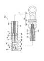
- FIG. 1is an overall view showing a cartridge and a clip system according to a first embodiment.
- FIG. 1is an overall view showing a cartridge and a clip system according to a first embodiment.
- FIG. 1is an overall view showing a cartridge and a clip system according to a first embodiment. It is a perspective view showing an engagement member of a first embodiment.
- Itis a schematic diagram which shows the usage aspect of the cartridge and the clip system which concern on 1st embodiment.
- Itis a schematic diagram which shows the usage aspect of the cartridge and the clip system which concern on 1st embodiment.
- Itis a schematic diagram which shows the usage aspect of the cartridge and the clip system which concern on 1st embodiment.
- Itis a schematic diagram which shows the usage aspect of the cartridge and the clip system which concern on 1st embodiment.
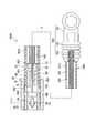
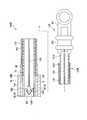
- FIG. 7is an overall view showing a modified example of the cartridge and the clip system according to the first embodiment.
- FIG. 7is an overall view showing a modified example of the cartridge and the clip system according to the first embodiment.
- Itis a schematic diagram which shows the cartridge and the clip system which concern on 2nd embodiment.
- Itis a schematic diagram which shows the cartridge and the clip system which concern on 2nd embodiment.
- Itis a schematic diagram which shows the cartridge and clip system which concern on 3rd embodiment.
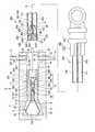
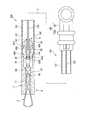
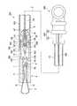
- 1 to 3are overall views showing a cartridge 1 and a clip system 200 according to this embodiment.
- FIG. 1 to FIG. 3are views showing an aspect at each step of using the cartridge 1.
- the clip system 200includes a clip unit 4, an applicator 100, a cartridge 1, and a pusher 2.
- the clip system 200is a system in which the applicator 100 to which the clip unit 4 is attached is inserted into a publicly known endoscope insertion portion so that the clip unit 4 can be left inside the body.
- the clip system 200is configured such that the clip unit 4 can be attached to the applicator 100 multiple times using the cartridge 1.
- the center line in the longitudinal direction when the applicator 100 extends linearlyis referred to as the longitudinal axis C.
- the operation unit 160 side of the applicator 100is referred to as a proximal side, and the side opposite to the proximal side in the longitudinal axis C direction and provided with the clip unit 4 is referred to as a distal side.
- the clip unit 4includes a housing 7 and an arm member 3. As shown in FIG. 1, the housing 7 has a tubular shape with a hole 70 penetrating in the longitudinal axis C direction.
- the hole 70 of the housing 7is a circular hole, and is formed by communicating a first insertion hole 71 (insertion hole) formed on the proximal side and a second insertion hole 72 formed on the distal side. There is.
- the first insertion hole 71is an elongated hole having a larger opening diameter than the second insertion hole 72.
- the first insertion hole 71has an opening diameter in which a sheath described later can be placed.
- a stepis formed at a boundary portion between the first insertion hole 71 and the second insertion hole 72, and a distal end of the first insertion hole 71 extends from the proximal end of the second insertion hole 72 to the longitudinal axis C.
- a distal wall 74is formed that extends outwardly in a perpendicular direction.
- the second insertion hole 72has an opening size into which the arm member 3 can be inserted.
- the distal end portion of the second insertion hole 72is formed with a tapered surface 73 that slightly expands toward the distal end surface of the housing 7.
- the housing 7is made of metal material such as stainless steel, titanium alloy (Ti-6AL-4V, etc.), cobalt chrome alloy, polyphthalamide (PPA), polyamide (PA), etc. It is made using a resin material.
- the arm member 3has one or more arms 31.
- the arm member 3includes a pair of arms 31 (first arm, second arm) and a connecting portion 33 on the proximal side of each arm 31.
- the arm member 3is made of, for example, a thin and slender plate made of metal such as stainless steel, cobalt chrome alloy, and titanium.
- Each of the pair of arms 31has a U-shaped connecting portion 33 formed by bending in the thickness direction in the middle portion of a thin and long plate, and both ends of the plate serve as the pair of arms 31.
- An end portion of each arm 31 on the opposite side of the connection portion 33is formed with a claw portion 32 bent in a direction toward each other.
- the pair of arms 31has a bending tendency in a direction in which they are separated from each other from the connecting portion 33 side toward the claw portion 32 side.
- the clip unit 4further includes a connecting member 9.
- the connecting member 9is a member that connects the arm member 3 and the operation wire 103.
- the connecting member 9is provided in the housing 7 at the proximal end of the arm member 3.
- the connecting member 9includes a first connecting body 92 and a second connecting body 93, and is configured by engaging the first connecting body 92 and the second connecting body 93 side by side in the longitudinal axis C direction. ..
- the first connecting body 92is located at the proximal portion of the connecting member 9 and is engaged with the operation wire 103.
- a wire engaging portion 94is provided at the proximal end of the first connecting body 92.
- the wire engagement portion 94includes an engagement hole 941, a pair of engagement arms 942, and a locking portion 943.
- the engagement hole 941is a hole that opens in the proximal end surface of the first coupling body 92, and has a size that allows the connector 104 of the operation wire 103 described below to be inserted.
- a pair of engagement arms 942are provided at the proximal edge of the engagement hole 941 so as to project in the proximal direction.
- the pair of engagement arms 942are each configured to be able to bend outward in the radial direction of the first coupling body 92.
- a locking portion 943is provided at each of the proximal ends of the pair of engagement arms 942.
- the locking portion 943is provided at a position facing the engagement hole 941 and covering the opening.
- the distal portion of the first coupling body 92is provided with a cylindrical portion 921 extending distally along the longitudinal axis C direction and a conical portion 922.
- the conical portion 922is provided at the distal end of the columnar portion 921, and the pointed end is disposed at the distal end of the first coupling body 92.
- the diameter of the proximal portion of the conical portion 922is larger than the diameter of the cylindrical portion 921.
- the second connecting body 93is located on the distal side of the first connecting body 92 and is engaged with the arm member 3.
- the second connecting body 93includes a connecting portion 931 forming a proximal region and a hook 932 forming a distal region.
- the connecting portion 931includes an engaging hole 933, a pair of engaging arms 934, and a locking portion 935 at the proximal end portion.
- the engagement hole 933, the pair of engagement arms 934, and the locking portion 935have the same configuration as the wire engagement portion 94 of the first coupling body 92.
- the conical portion 922 of the first connecting body 92is inserted into the engaging hole 933 of the second connecting body 93, and the conical portion 922 is engaged by the pair of engaging arms 934 and the locking portion 935 of the second connecting body 93.
- the first connecting body 92 and the second connecting body 93are connected.
- the hook 932is a hook that is substantially L-shaped when viewed from the direction of arrow A in FIG. 1, and is provided so as to project farther than the connecting portion 931.
- the arm 31 of the arm member 3 and the connecting member 9are locked in the first insertion hole 71 of the housing 7.
- the L-shaped end portion of the hook 932 of the second connecting body 93is arranged inside the curved portion of the connecting portion 33 of the arm member 3, and is inserted into the first insertion hole 71 in this state. There is. With this configuration, the hook 932 does not disengage from the connecting portion 33 in the longitudinal axis C direction and the radial direction of the housing 7 in the first insertion hole 71, and the arm member 3 and the connecting member 9 are engaged with each other.
- the first insertion hole 71has a size such that the locked arm member 3 and the connecting member 9 can advance and retreat in the first insertion hole 71 in the longitudinal axis C direction. Although details will be described later, the arm member 3 and the connecting member 9 can be moved back and forth in the first insertion hole 71 as the operation wire 103 connected to the first connected body 92 is moved back and forth.
- the arm member 3is configured such that the pair of arms 31 can be opened and closed according to the relative position of the arm member 3 with respect to the first insertion hole 71 in the longitudinal axis C direction.
- the applicator 100includes a sheath 101, an operation wire 103, an engagement member 8, and an operation section 160.
- the operation unit 160includes an operation body 161 and a slider 162.
- the slider 162is provided slidably in the longitudinal axis C direction with respect to the operation body 161.
- the sheath 101is a flexible, long tubular member.
- the sheath 101has a conduit 111 formed along the longitudinal axis C over the entire length.
- the sheath 101is, for example, a coil sheath formed by tightly winding a wire made of stainless steel such as SUS301 around the longitudinal axis C.
- the proximal end of the sheath 101is connected to the operation body 161 of the operation unit 160.
- the conduit 111opens into the distal end 106 of the sheath 101.
- the distal end portion 105 of the sheath 101is formed with a convex portion 109 that projects radially inward from the inner peripheral surface of the duct 111.
- the convex portion 109projects annularly from the inner peripheral surface of the entire circumference of the conduit 111.
- the opening of the conduit 111is narrowed at the position of the convex portion 109, but the conduit 111 is secured to such an extent that the operation wire 103 and the intermediate portion 83 of the engagement member 8 described later can be advanced and retracted.
- a through hole (opening) 107 communicating with the inside and outside of the sheath 101is formed at the distal end 105 of the sheath 101.
- the through hole 107is located closer to the proximal side than the convex portion 109.
- a pair of through holes 107are formed at positions facing each other on the circumference of the sheath 101.
- the through hole 107has an opening into which the pusher 2 can be inserted.
- the operation wire 103is inserted into the sheath 101.
- the proximal end of the operating wire 103is fixed to the slider 162 of the operating portion 160, and the connector 104 is fixed to the distal end of the operating wire 103.
- the operation wire 103is formed of a metal single wire or a stranded wire.
- the connector 104is a member that connects the arm member 3 and the operation wire 103.
- the connector 104includes a connecting end 1041, an engaged portion 1042, and a recess 1043.
- the connecting end 1041has a tubular shape, and the distal end of the operating wire 103 is inserted and fixed to the operating wire 103.
- the engaged portion 1042is provided at the distal end portion of the connector 104.
- the engaged portion 1042has a conical shape, projects in the direction of the longitudinal axis C, and has a pointed end on the distal side.
- the recess 1043is located between the proximal end of the engaged portion 1042 and the connecting end 1041 and has a cylindrical shape with an outer diameter smaller than that of the engaged portion 1042 and the connecting end 1041.
- the engaging member 8is attached to the distal end portion of the operation wire 103, and is provided so as to be able to project and retract from the distal end of the sheath 101.
- FIG. 4shows a perspective view of the engaging member 8.
- the engagement member 8includes a proximal end portion 81, an intermediate portion 83, and a distal end portion 82 along the longitudinal axis C direction, and the engaging member 8 extends along the longitudinal axis C direction over the entire length.
- An insertion hole 85extending in the direction is formed.
- the proximal end portion 81includes an annular portion 811 and a tapered portion 812.
- the annular portion 811has an annular shape whose diameter is smaller than the inner diameter of the conduit 111 of the sheath 101.
- the tapered portion 812is located closer to the proximal side than the annular portion 811, and has a substantially conical shape in which the diameter is reduced in the proximal direction from the outer peripheral end portion on the proximal side of the annular portion 811.
- the distal end portion 82has a substantially cylindrical shape.
- a chamfered beveled surface 823is provided at a boundary portion between the outer peripheral surface of the distal end portion 82 and the distal end surface 822.
- the middle portion 83is located between the proximal end 81 and the distal end 82.
- the intermediate portion 83has a substantially cylindrical shape whose diameter is smaller than the outer diameters of the annular portion 811 of the proximal end portion 81 and the distal end portion 82. Therefore, in the engaging member 8, the intermediate portion 83 between the proximal end portion 81 and the distal end portion 82 is a recess.
- a first contact wall 813 extending in the direction intersecting the longitudinal axis Cis provided between the proximal end of the intermediate portion 83 and the distal end of the outer peripheral portion of the annular portion 811.
- a second contact wall 821 extending in a direction intersecting the longitudinal axis Cis provided between the distal end of the intermediate portion 83 and the proximal end of the outer peripheral portion of the distal end portion 82.
- a pair of slits 86 extending from the distal end surface 822 of the engaging member 8 in the longitudinal axis C directionare provided.
- the pair of slits 86are opposed to each other with the central axis of the cylindrical distal end portion 82 interposed therebetween, that is, on the diameter of the distal end portion 82. It is formed in two places.
- the pair of slits 86are formed so as to extend in the longitudinal axis C direction from the distal end surface 822 to the substantially central portion of the engaging member 8 in the longitudinal axis C direction. Therefore, the distal end portion 82 is connected to the intermediate portion 83 while being divided into a semicircle by the pair of slits 86.
- the pair of slits 86extend to the intermediate portion 83.
- the insertion hole 85has a different opening size with the substantially central portion of the engaging member 8 in the longitudinal axis C direction as a boundary.
- the opening size of the insertion hole 85is larger in the second insertion hole 852 in the distal portion than in the first insertion hole 851 in the proximal portion.
- the second insertion hole 852has an inner tapered surface 853 whose opening diameter increases toward the distal end surface 822.
- the pair of slits 86extend from the distal end surface 822 to the proximal end of the second insertion hole 852.
- the distal region of the intermediate portion 83is thinner than the proximal region of the intermediate portion 83 and the distal end portion 82.
- the engaging member 8is The distal side bends, and the divided distal ends 82 come closer to each other.
- the operation wire 103is inserted into the insertion hole 85 so that the operation wire 103 can move forward and backward.
- the distal portion of the operation wire 103penetrates the first insertion hole 71, and the connector 104 is inserted into the second insertion hole 852.
- the outer dimensions of the distal portion of the coupling end 1041 and the engaged portion 1042are larger than the opening dimension of the first insertion hole 71. Therefore, the connector 104 contacts the distal end of the first insertion hole 71 when retracting with respect to the engagement member 8. Therefore, the operation wire 103 does not come off from the engagement member 8 to the proximal side.
- the engagement member 8is arranged in the distal end portion 105 of the sheath 101.
- the intermediate portion 83 of the engaging member 8is inserted inside the annular convex portion 109 of the sheath 101.
- the engagement member 8is provided so as to be able to advance and retract within the distal end portion 105 of the sheath 101.
- the opening diameter inside the convex portion 109is larger than the outer diameter of the intermediate portion 83 and smaller than the outer diameters of the proximal end portion 81 and the distal end portion 82.
- the engagement member 8is located between the position where the first contact wall 813 of the proximal end 81 contacts the protrusion 109 and the position where the second contact wall 821 of the distal end 82 contacts the protrusion 109. It is configured to be able to move forward and backward.
- the engaging member 8advances, the first abutment wall 813 of the proximal end 81 abuts the protrusion 109, and further advancement is restricted.
- the engaging member 8 retractsthe second contact wall 821 of the distal end portion 82 abuts the convex portion 109 and further retracting is restricted. Therefore, the amount of forward/backward movement of the engagement member 8 with respect to the sheath 101 is defined by the distance between the first contact wall 813 and the second contact wall 821.
- the length of the distal end portion 82 in the longitudinal axis C directionis slightly shorter than the length from the distal end 106 of the sheath 101 to the distal end of the convex portion 109. Therefore, as shown in FIG. 1, when the position of the engagement member 8 with respect to the sheath 101 is at the most retracted position, the engagement member 8 is housed inside the sheath 101 over the entire length. When the engaging member 8 is in the retracted position, the proximal end portion 81 is arranged at the position of the through hole 107 of the sheath 101 in the longitudinal axis C direction.
- the pusher 2is configured to move the pusher 2 with respect to the sheath 101 by contacting the engaging member 8 and pushing the engaging member 8.
- the pusher 2is provided in the cartridge 1.
- the cartridge 1accommodates the clip unit 4 before use, and the clip unit 4 can be attached to the applicator 100.
- the cartridge 1includes a main body 11, and the main body 11 is provided with a pusher 2.
- the main body 11has a storage portion 12 in which the clip unit 4 is stored.
- the storage portion 12is a hollow portion formed according to the outer shape of the clip unit 4.
- the storage portion 12has a first storage portion 121 (insertion hole) for storing the housing 7 of the clip unit 4, and a second storage portion 122 for storing the distal region of the arm member 3 protruding from the housing 7.
- First storage section 121has an elongated shape.
- the first accommodating portion 121has an insertion hole (opening) 15 which is opened at the base end of the main body 11 and into which the sheath 101 can be inserted along the longitudinal axis C direction.
- the first storage portion 121is configured to be insertable along the longitudinal axis C direction (axial direction).
- the first storage portion 121is longer than the length of the housing 7 in the longitudinal axis C direction.
- the pusher 2is provided at the proximal end of the main body 11.
- the main body 11has a slide hole 13 that communicates between the proximal portion of the first storage portion 121 and the outer surface of the main body 11.
- the slide hole 13is a hole extending in a direction orthogonal to the longitudinal axis C direction.
- the pusher 2is an elongated rod-shaped member and is inserted into the slide hole 13. As shown in FIGS. 1 and 3, the pusher 2 is configured to be movable in a direction intersecting the longitudinal axis C of the first storage portion 121.
- the pusher 2is provided with a biasing member (not shown), and in a natural state in which the pusher 2 is not subjected to an external force, as shown in FIG.
- the pusher 2has an inclined surface 21 that is inclined with respect to the longitudinal axis C.
- the inclined surface 21has a shape in which a corner portion on the distal side of the inner end surface 22 of the pusher 2 facing the first storage portion 121 side is chamfered.
- FIG. 9is a flowchart showing the engagement method according to this embodiment.
- the clip unit 4is housed in the housing portion 12 of the cartridge 1 in advance with the arm 31 in the distal region of the arm member 3 protruding from the housing 7 to the distal side.
- the clip unit 4 housed in the housing 12has the housing 7 housed in the distal region of the first housing 121.
- a space into which the sheath 101 is insertedis formed on the proximal side of the housing 7.
- the cartridge 1is brought close to the distal end 106 of the sheath 101, and the distal end 106 is inserted into the insertion hole 15 of the first storage portion 121 of the cartridge 1 (first step S1).
- the sheath 101is advanced to the cartridge 1 side, and the distal end 106 of the sheath 101 is brought into contact with the proximal end of the housing 7, as shown in FIG.
- the operatoroperates the slider 162, advances the operation wire 103, and pushes the engaged portion 1042 into the engagement hole 941 side.
- the tip of the engaged portion 1042enters the engaging hole 941 from between the pair of engaging arms 942, bends in the direction in which the pair of engaging arms 942 separates, and the engaged portion 1042 engages with the engaging hole 941. Inserted inside. Since the engaging hole 941 of the wire engaging portion 94 has a shape similar to the shape of the engaged portion 1042, the engaged portion 1042 is arranged in the proximity of the engaging hole 941.
- the engaged portion 1042When the engaged portion 1042 is inserted into the engaging hole 941, the pair of engaging arms 942 return to their natural positions, and the locking portion 943 abuts on the proximal end surface of the engaged portion 1042. As a result, the engaged portion 1042 is engaged in the engaging hole 941 and the distal end of the operation wire 103 is engaged with the connecting member 9.
- the pusher 2is movable with respect to the sheath 101, and when the pusher 2 moves with respect to the sheath 101, the pusher 2 comes into contact with the engaging member 8 and pushes the engaging member 8 against the housing, thereby separating the engaging member 8 from the sheath 101 and the housing. Both are engaged (second step S2).
- the pusher 2 protruding into the first storage portion 121passes through the through hole 107 of the sheath 101 and contacts the proximal end portion 81 of the engaging member 8.
- the inclined surface 21 of the pusher 2is pushed in while contacting the tapered portion 812 of the proximal end portion 81, as shown in FIG. As a result, the engagement member 8 advances distally.
- the engaging member 8When the pusher 2 is pushed to the innermost side with respect to the first insertion hole 71, the engaging member 8 is at the most advanced position, and the housing 7 and the sheath 101 are engaged with each other via the engaging member 8. Has been done. Therefore, when the operator releases the pressing force on the pusher 2 after pushing the pusher 2 into the first insertion hole 71 to the innermost side, the urging member provided in the pusher 2 returns the retracted position shown in FIG. .. In this state, the cartridge 1 is moved in the distal direction, and the clip unit 4 is taken out from the cartridge 1.
- the clip unit 4is inserted into the body through the treatment tool channel of the endoscope and brought close to the tissue to be ligated by the arm member 3. Since the housing 7 is engaged with the sheath 101 by the engaging member 8, when the sheath 101 is rotated about the longitudinal axis C, the housing 7 is also rotated and the arm 31 of the arm member 3 rotates about the longitudinal axis C. The orientation can be adjusted.
- the operation wire 103is moved forward with respect to the sheath 101 and the engaging member 8 as shown in FIG.
- the arm member 3advances with respect to the housing 7, and the pair of arms 31 projects from the second storage portion 122 to the distal side.
- the portions of the pair of arms 31 projecting distally from the second storage portion 122are released in a direction in which they are released from the pressing force of the second storage portion 122.
- the sheath 101 and the housing 7are engaged with each other via the engaging member 8, and the operation wire 103 is configured to be able to move forward and backward in this state. Therefore, the arm member 3 can move forward and backward with respect to the housing 7. Is. As a result, the tissue can be regripped by the arm member 3. That is, once the tissue is sandwiched by the pair of claw portions 32 of the arm member 3, the pair of arms 31 can be opened again by moving the arm member 3 forward relative to the housing 7. The state in which 32 holds the tissue can be released. Furthermore, when the arm member 3 is brought closer to the tissue again with the pair of arms 31 open and retracted relatively to the housing 7, the tissue can be sandwiched by the pair of claw portions 32 again.
- the operatorWhen the operator can grasp the tissue with the arm member 3 in a desired state, the operator retracts the slider 162 and retracts the operation wire 103 and the arm member 3.
- the operation wire 103 and the arm member 3retract while the tissue is held between the pair of claw portions 32, tension is applied to the connecting body 92.
- the pair of engaging arms 934 of the second coupling body 93are pushed and deformed by the conical portions 922 in the directions in which they are separated from each other, and the conical portions 922 fall out from the engaging holes 933.
- the engagement between the first connecting body 92 and the second connecting body 93is released.
- the pair of engagement arms 942 of the first connection body 92are tapered inside the second insertion hole 852. It abuts the surface 853.
- the pair of engaging arms 942 of the first connecting body 92maintains the engaged state of the engaged portion 1042.
- the pair of engagement arms 942apply a force in the backward direction while contacting the inner tapered surface 853. Therefore, as the operation wire 103 is retracted, a force is applied to the engagement member 8 in the proximal direction, and the engagement member 8 retracts with respect to the housing 7.
- the engaging member 8When the engaging member 8 is pushed proximally by the first connecting body 92, it disengages from the first insertion hole 71 as shown in FIG. 8, and the engagement between the sheath 101 and the housing 7 by the engaging member 8 is released. To be done. That is, the engagement releasing operation between the first connecting body 92 and the second connecting body 93 and the engagement releasing operation between the sheath 101 and the housing 7 by the engaging member 8 are performed substantially at the same time. After the engagement between the housing 7 and the sheath 101 is released, the sheath 101 is retracted and the tissue is ligated by the clip unit 4.
- the applicator 100After ligating the tissue with the first clip unit 4, the applicator 100 is pulled out of the body, and the second clip unit 4 is loaded on the applicator 100 again as needed. Specifically, after the applicator 100 is removed from the body, the operation wire 103 is projected from the distal end 106 of the sheath 101, and the first connection body 92 connected to the connector 104 of the operation wire 103 is removed. Next, the second cartridge 1 containing the second clip unit 4 is prepared. The operation wire 103 is retracted, the sheath 101 is inserted into the cartridge 1 by the same method as described above, and the cartridge 1 and the sheath 101 are engaged with each other via the engaging member 8. As a result, the clip unit 4 is loaded on the sheath 101. In this way, when ligating a plurality of places of the tissue with the plurality of clip units 4, the clip units can be continuously loaded without exchanging the applicator 100.
- the clip unit 4can be easily loaded in the applicator 100, and the clip unit 4 can be repeatedly loaded in the applicator 100.
- the distal end portion 105 of the sheath 101is inserted into the insertion hole 15 of the main body 11, and the pusher 2 is movable in the direction intersecting with the main body 11. Further, the pusher 2 can push the engaging member 8 in the forward direction with respect to the housing 7. By engaging the engaging member 8 with both the housing 7 and the sheath 101 by the pusher 2, the engaging member 8 engages with the sheath 101 and the housing 7. As a result, the clip unit 4 can be attached to the applicator 100 by a simple operation of pushing the pusher 2 with the sheath 101 inserted in the main body 11.
- the pusher 2is configured to be movable in the direction intersecting the longitudinal axis C of the elongated first insertion hole 71. That is, the inserting direction of the sheath 101 into the cartridge 1 and the pressing direction of the engaging member 8 against the cartridge 1 are along the longitudinal axis C.
- the pusher 2moves in the direction intersecting the longitudinal axis C and pushes the engaging member 8. Therefore, the engagement member 8 is smoothly moved in the longitudinal axis C direction by moving the pusher 2 in a direction different from the movement direction of the operation wire 103 while maintaining the state in which the sheath 101 is inserted in the main body 11 of the cartridge 1. You can press it. As a result, it is possible to engage the sheath 101 and the housing 7 by pushing the pusher 2 and advancing the engaging member 8 while keeping the cartridge 1 in contact with the distal end 106 of the sheath 101.
- the engagement member 8can be advanced with the sheath 101 inserted in the first insertion hole 71.
- the pusher 2is accommodated in the sheath 101 by protruding into the first insertion hole 71 through the through hole 107 formed in the outer peripheral surface of the sheath 101. Contact the mating member 8. As a result, with the sheath 101 inserted in the first insertion hole 71, the pusher 2 can contact the engagement member 8 arranged in the sheath 101, and the engagement member 8 can be pushed by the pusher 2. ..
- the pusher 2is provided with the inclined surface 21, and the inclined surface 21 is configured to be capable of contacting the engaging member 8.
- the engaging member 8can be advanced while moving the pusher 2 in a direction different from the forward direction of the engaging member 8.
- the proximal end portion 81 of the engaging member 8has the tapered portion 812
- the pusher 2has the inclined surface 21
- the tapered portion 812 and the inclined surface 21are in contact with each other.
- the clip systemis not limited to this configuration example, and may have a configuration in which one of the pusher and the engaging member has an inclined surface.
- the cartridge 1is attached to the distal end 106 of the sheath 101 to project the engagement member 8 from the distal end 106 of the sheath 101.
- the engaging member 8can be moved with a simpler configuration. Can be pushed.
- the sheath 101can be inserted in the longitudinal axis C direction from the proximal side of the first insertion hole 71
- the insertion form of the sheath into the insertion holeis not limited to this.
- the sheathmay be inserted into the insertion hole from the side of the main body of the cartridge.
- the pusher 2projects into the first insertion hole 71 through the through hole 107 formed in the outer peripheral surface of the sheath 101 to contact the engagement member 8 housed in the sheath 101.
- the mode in which the pusher 2 projects into the first insertion hole 71is not limited to this.
- the through hole 107is covered with an elastically deformable elastic film 1071, and the elastic film 1071 is pressed by the pusher 2 to deform the elastic film 1071. You may project in the 1st insertion hole 71.
- the pusher 2can push the engaging member 8 with the elastic film 1071 sandwiched between the pusher 2 and the engaging member 8.
- FIGS. 12 and 13a clip system 200A according to the second embodiment will be described with reference to FIGS. 12 and 13.
- the same components as those already described in the first embodimentwill be assigned the same reference numerals and overlapping description will be omitted.
- the present embodimentdiffers from the first embodiment in the configuration in which the pusher pushes the engagement member against the housing 7.
- the sheath 101 of this embodimentis a coil sheath that does not have the convex portion 109 and the through hole 107.
- the pusher 2Ais housed in the sheath 101.
- the pusher 2A of the present embodimentis provided at the distal end 1021 of the inner sheath 102.
- the inner sheath 102is inserted into the sheath 101, and the operation wire 103 is inserted inside. That is, the inner sheath 102 is arranged coaxially with the sheath 101 between the operation wire 103 and the sheath 101.
- the inner sheath 102is a coil sheath.
- a proximal end portion of the inner sheath 102is fixed to a second slider 163 provided on the operation portion 160A.
- the second slider 163can move forward and backward with respect to the operation body 161.
- the pusher 2Ais a substantially cylindrical member and is fixed to the distal end 1021 of the inner sheath 102. Therefore, the inner sheath 102 moves back and forth with respect to the sheath 101 by the forward/backward operation of the second slider 163, and the pusher 2A moves forward/backward as the inner sheath 102 moves forward/backward.
- the pusher 2Ais formed with an insertion hole 27 penetrating in the longitudinal axis C direction.
- the pusher 2Ais fixed to the inner sheath 102 with the insertion hole 27 and the central axis of the conduit 1022 of the inner sheath 102 arranged coaxially.
- the engagement member 8A of the present embodimentis made of a substantially cylindrical tubular member.
- the engagement member 8Ais inserted into the conduit 111 of the distal end portion 105 of the sheath 101.
- the outer peripheral surface of the engaging member 8Ahas an outer dimension that allows frictional engagement with the inner surface of the sheath 101 and the inner surface of the first storage portion 121.
- the engagement member 8Acan advance and retreat in the pipe line 111 and the first storage part 121.
- the engagement member 8Africtionally engages with the inner surface of the sheath 101 and the first storage portion 121.
- the engagement member 8Ais formed with an insertion hole 85A extending in the longitudinal axis C direction over the entire length.
- a distal pusher 108is fixed to the operation wire 103.
- the distal pusher 108is fixed to the distal end region of the operation wire 103, which is closer to the proximal side than the connector 104.
- the distal pusher 108is a cylindrical member.
- the diameter of the distal pusher 108is smaller than the inner diameter of the sheath 101 and the inner diameter of the first storage portion 121 of the housing 7, and larger than the inner diameter of the insertion hole 85A of the engaging member 8A.
- the operation wire 103is inserted into the sheath 101 and the inner sheath 102, and the distal portion is inserted into the insertion hole 85A of the engaging member 8A.
- the connector 104 and the distal pusher 108are arranged on the distal side of the engagement member 8A.
- the cartridge 1Adoes not include the pusher 2 and the slide hole 13 of the first embodiment, and other configurations are the same as those of the first embodiment.
- the distal end 106 of the sheath 101is inserted into the insertion hole 15 of the cartridge 1A in which the clip unit 4 is housed, and brought into contact with the proximal end 75 of the housing 7. Similar to the first embodiment, the operation wire 103 is advanced to push the engaged portion 1042 into the engaging hole 941 side of the clip unit 4 and engage the connector 104 with the connecting member 9.
- the second slider 163is advanced with respect to the operation body 161, and the inner sheath 102 is advanced with respect to the sheath 101.
- the second slider 163is further advanced.
- the pusher 2Apushes the engagement member 8A in the distal direction
- the engagement member 8Aadvances
- the pusher 2Aprojects further to the distal side than the distal end 106 of the sheath 101. As shown in FIG.
- the cartridge 1Ais removed from the clip unit 4, and the mounting of the clip unit 4 on the sheath 101 is completed. Then, as in the first embodiment, the distal end portion 105 of the sheath 101 is inserted into the body, and the target tissue is ligated with the clip unit 4.
- the engagement between the housing 7 and the sheath 101is released.
- the slider 162 of the operation unit 160is slid proximally.
- the pair of engagement arms 934 of the second coupling body 93are pushed by the conical portions 922 in a direction in which they are separated from each other and are deformed, and the conical portions 922 fall out from the engaging holes 933.
- the engagement between the first connecting body 92 and the second connecting body 93is released.
- the distal pusher 108pushes the engagement member 8A proximally, the engagement member 8A moves proximally, and the engagement between the housing 7 and the sheath 101 by the engagement member 8A is released. ..
- the tissueis ligated by the clip unit 4.
- the clip unit 4can be easily loaded into the applicator 100, and the clip unit can be repeatedly loaded into the applicator 100, as in the first embodiment.
- the pusher 2Ais configured to be able to come into contact with the proximal end 801 of the engaging member 8A by advancing and retracting with respect to the operation wire 103, and the engaging member 8A is the first housing of the housing 7. It can be press-fitted into the portion 121. As a result, the housing 7 and the sheath 101 can be engaged by moving the engaging member 8A in the sheath 101 forward and backward. Therefore, the housing 7 and the sheath 101 can be engaged with each other with a simple configuration.
- the engaging member 8Acan be pushed and moved to the proximal side by retracting the operation wire 103. Therefore, the engagement member 8A can be moved back and forth with respect to the sheath 101 and the housing 7. As a result, the clip unit 4 can be attached to and detached from the sheath 101. Further, the clip unit 4 can be repeatedly loaded in the applicator 100.
- a clip system 200A according to the third embodimentwill be described with reference to FIGS. 14 and 15.
- the structure of the engaging member and the structure in which the pusher pushes the engaging member against the housing 7are different from the first embodiment.
- the applicator 100Bincludes an outer sheath 119 as shown in FIG.
- the outer sheath 119functions as a pusher of the engagement member 8B.
- the outer sheath 119is arranged coaxially with the sheath 101, and the sheath 101 having the operation wire 103 inserted therein is inserted therein.
- a grip portion 1191is provided at the proximal end of the outer sheath 119.
- the outer sheath 119is provided so as to be movable back and forth in the longitudinal axis C direction with respect to the sheath 101.
- the outer sheath 119includes an engaging member 8B.
- the engagement member 8Bis fixed to the distal end of the outer sheath 119.
- the engagement member 8Bis a tubular member into which the sheath 101 and the housing 7 can be inserted.
- the engagement member 8Bis, for example, a soft resin tube or a coil whose diameter can be reduced.
- the engagement member 8Bis provided so as to be able to advance and retreat with respect to the sheath 101 and the housing 7 while being in contact with the outer peripheral surfaces of the sheath 101 and the housing 7.
- the engaging member 8BSince the engaging member 8B is fixed to the distal end of the outer sheath 119, the engaging member 8B advances toward the housing 7 in the distal direction as the outer sheath 119 advances.
- the engaging member 8Bis configured to be able to engage the housing 7 and the sheath 101 by friction between the outer peripheral surface of the housing 7 and the outer peripheral surface of the sheath 101.
- the sheath 101 of this embodimentis a coil sheath that does not include the convex portion 109 and the through hole 107.
- the same cartridge 1A as that in the second embodimentis used.
- the distal end 106 of the sheath 101is inserted into the insertion hole 15 of the cartridge 1A in which the clip unit 4 is housed, and brought into contact with the proximal end 75 of the housing 7. Similar to the first embodiment, the operation wire 103 is advanced to push the engaged portion 1042 into the engaging hole 941 side of the clip unit 4, and the connector 104 is engaged with the connecting member 9.
- the operatorgrasps the grasping portion 1191 and advances the outer sheath 119 with respect to the sheath 101.
- the engaging member 8Badvances, projects further distal than the distal end 106 of the sheath 101, and the distal end 802 of the engaging member 8B enters into the insertion hole 15 of the cartridge 1A. ..
- the distal end 106 of the sheath 101 and the proximal end 75 of the housing 7are inserted into the engaging member 8B as shown in FIG.
- the inner peripheral surface of the engagement member 8Bcontacts the outer peripheral surfaces of the sheath 101 and the housing 7, and the distal end 106 of the sheath 101 and the proximal end 75 of the housing 7 are engaged with each other via the engagement member 8B.
- the cartridge 1Ais removed from the clip unit 4, and the mounting of the clip unit 4 on the sheath 101 is completed. Then, as in the first embodiment, the distal end portion 105 of the sheath 101 is inserted into the body, and the target tissue is ligated with the clip unit 4.
- the engagement between the housing 7 and the sheath 101is released.
- the grip portion 1191 of the outer sheath 119is slid proximally.
- the engaging member 8Bmoves to the proximal side, and the engagement between the housing 7 and the sheath 101 by the engaging member 8B is released.
- the pair of engagement arms 934 of the second coupling body 93are pushed and deformed by the conical portions 922 in the directions in which they are separated from each other, and the conical portions 922 are engaged. Fall out of the hole 933.
- the engagement between the first connecting body 92 and the second connecting body 93is released.
- the tissueis ligated by the clip unit 4.
- the engagement between the housing 7 and the sheath 101 by the engagement member 8Bmay be released after the operation for releasing the engagement between the first connecting body 92 and the second connecting body 93.
- the clip unit 4can be easily loaded in the applicator 100B, and the clip unit 4 can be repeatedly loaded in the applicator 100B, as in the first embodiment.
- the engaging member 8Bis fixed to the distal end of the outer sheath 119, and the engaging member 8B can be moved forward and backward by moving the outer sheath 119 forward and backward relative to the sheath 101.
- the housing 7 and the sheath 101can be engaged by the forward movement of the engaging member 8B outside the sheath 101. Therefore, the housing 7 and the sheath 101 can be engaged with each other with a simple configuration.
- the engaging member 8Bsince the outer sheath 119 is provided with the engaging member 8B, the engaging member 8B is moved to the proximal side by retracting the outer sheath 119. Therefore, the engaging member 8B can be moved back and forth with respect to the sheath 101 and the housing 7. As a result, the clip unit 4 can be attached to and detached from the sheath 101. Further, the clip unit 4 can be repeatedly loaded in the applicator 100B.
- the clipcan be easily reloaded into the applicator. It is possible to provide a cartridge, a clip system, and an engaging method that can easily select right and left by using a switch attached to a housing.
Landscapes
- Health & Medical Sciences (AREA)
- Surgery (AREA)
- Life Sciences & Earth Sciences (AREA)
- Heart & Thoracic Surgery (AREA)
- Nuclear Medicine, Radiotherapy & Molecular Imaging (AREA)
- Vascular Medicine (AREA)
- Engineering & Computer Science (AREA)
- Biomedical Technology (AREA)
- Reproductive Health (AREA)
- Medical Informatics (AREA)
- Molecular Biology (AREA)
- Animal Behavior & Ethology (AREA)
- General Health & Medical Sciences (AREA)
- Public Health (AREA)
- Veterinary Medicine (AREA)
- Surgical Instruments (AREA)
Abstract
Description
Translated fromJapanese本発明は、体内組織を結紮するクリップ用のカートリッジ、クリップシステムおよび係合方法に関する。The present invention relates to a clip cartridge, a clip system, and an engaging method for ligating body tissue.
従来、生体組織に生じた開口の閉鎖や止血処置等を行うために、クリップにより処置対象組織を結紮するクリップ装置が知られている。クリップ装置は、操作部と、シースと、シース内に相通されて操作部と接続される操作ワイヤとを備える。クリップ装置は、シースが内視鏡のチャンネルに挿入され、チャンネルを経由して体内に挿入される。Conventionally, a clip device has been known which ligates a tissue to be treated with a clip in order to close an opening generated in a living tissue or perform a hemostasis treatment. The clip device includes an operating portion, a sheath, and an operating wire that is in communication with the sheath and is connected to the operating portion. In the clip device, the sheath is inserted into the channel of the endoscope, and is inserted into the body via the channel.
例えば、特許文献1には、一対のジョーがハウジングに回動可能に支持されたクリップ装置が開示されている。一対のジョーは、駆動ワイヤの先端ヘッドが接続されたドライバーと一対のジョーの基端部とがラック-ピニオン構造により接続され、駆動ワイヤの進退に伴い一対のジョーがハウジングに対して回動して開閉する。For example,
クリップを体内に留置するクリップ装置は、シースの先端にクリップが接続された状態で体内に挿入される。駆動ワイヤの操作によりクリップのアーム(一対のジョー)を開いて組織に当接させた後、クリップを閉じることにより組織を結紮する。その後、クリップと駆動ワイヤとの接続を解除してクリップを体内に留置する。そのため、クリップを体内へ留置する前は、クリップと内視鏡のチャンネルの先端とが接続されており、クリップの留置後は、クリップと内視鏡のチャンネルの先端との接続を解除する必要がある。 The clip device that holds the clip inside the body is inserted into the body with the clip connected to the tip of the sheath. The arm of the clip (a pair of jaws) is opened by operating the drive wire to bring it into contact with the tissue, and then the clip is closed to ligate the tissue. After that, the clip is disconnected from the drive wire and the clip is placed in the body. Therefore, before placing the clip in the body, the clip and the tip of the endoscope channel are connected, and after placing the clip, it is necessary to release the connection between the clip and the tip of the endoscope channel. is there.
特許文献1のクリップ装置では、筒コネクタ内に接続ブロックが設けられており、駆動ワイヤの操作により接続ブロックを筒コネクタから突出させてハウジングに圧入し、接続ブロックを介してハウジングと筒コネクタとが固定されている。In the clip device of
内視鏡装置を用いて組織結紮用のクリップを体内に留置する場合、処置具の挿入性を考慮すると駆動力伝達用のワイヤとしては柔軟なワイヤが好ましい。しかし、特許文献1のクリップ装置では、接続ブロックをハウジングに圧入する際に駆動ワイヤを押し込んでも、駆動ワイヤの押込み力より接続ブロックとハウジングとの摩擦力の方が大きい。その結果、接続ブロックをハウジングに圧入できないため、ハウジングと筒コネクタとを固定できない。あるいは、接続ブロックが筒コネクタ内に押し戻され得るため、ハウジングと筒コネクタとを固定できない。When a tissue ligation clip is placed in the body using an endoscopic device, a flexible wire is preferable as the drive force transmission wire in consideration of insertability of the treatment tool. However, in the clip device of
クリップによる処置対象組織の結紮を連続して行う場合がある。従来、クリップで組織を結紮した後、次の結紮を行う場合、予めクリップが装着された次のクリップ装置にクリップ装置全体を交換してクリップで処置対象組織の結紮が行われている。この他、一つのシースおよび操作部を用い、シースの先端にクリップを再装填して次の結紮を行う方法がある。特許文献1のクリップ装置では、接続ブロックをシースの先端側へ押し込むことが難しく、クリップの再装填に不向きである。∙ The tissue to be treated may be ligated continuously with a clip. Conventionally, when the next ligation is performed after ligating a tissue with a clip, the entire clip device is replaced with the next clip device to which the clip is attached in advance, and the tissue to be treated is ligated with the clip. In addition to this, there is a method of reloading a clip on the tip of the sheath and performing the next ligation by using one sheath and the operating portion. In the clip device of
本発明は、上述した事情に鑑みてなされたものであり、クリップをアプリケータに容易に再装填できるカートリッジ、クリップシステム、およびクリップ係合方法を提供することを目的とする。The present invention has been made in view of the above-mentioned circumstances, and an object of the present invention is to provide a cartridge, a clip system, and a clip engaging method by which a clip can be easily reloaded in an applicator.
本発明の第一の態様に係るカートリッジは、アーム部材および前記アーム部材が挿入される筒状のハウジングを備えるクリップユニットを収容し、前記ハウジングと係合可能なシースおよび前記アーム部材と係合可能な操作ワイヤを有するアプリケータに前記クリップユニットを装着可能に構成されたカートリッジであり、前記シースが挿入される挿入孔を有する本体と、前記本体に対して移動可能なプッシャーと、を備え、前記プッシャーは、前記シースが前記挿入孔に挿入された状態で前記本体に対して移動することで、前記シースに設けられた係合部材と接触可能であり、前記係合部材と接触しながら前記係合部材を前記ハウジングに対して押し、前記係合部材を前記ハウジングおよび前記シースの両方に係合させることで前記シースと前記ハウジングとを係合させるように構成されている。A cartridge according to a first aspect of the present invention accommodates a clip unit including an arm member and a tubular housing into which the arm member is inserted, and is capable of engaging with the housing and the arm member. Is a cartridge configured such that the clip unit can be attached to an applicator having a different operation wire, the main body having an insertion hole into which the sheath is inserted, and a pusher movable with respect to the main body, The pusher can be brought into contact with an engagement member provided on the sheath by moving with respect to the main body in a state where the sheath is inserted into the insertion hole, and the pusher can be brought into contact with the engagement member while contacting the engagement member. The sheath and the housing are engaged by pushing the mating member against the housing and engaging the engaging member with both the housing and the sheath.
本発明の第二の態様は、第一の態様に係るカートリッジにおいて、前記挿入孔は、前記シースを配置可能な細長形状を有し、前記プッシャーは、前記挿入孔の長手軸と交差する方向に移動可能に構成されていてもよい。A second aspect of the present invention is the cartridge according to the first aspect, wherein the insertion hole has an elongated shape in which the sheath can be arranged, and the pusher is arranged in a direction intersecting a longitudinal axis of the insertion hole. It may be configured to be movable.
本発明の第三の態様は、第二の態様に係るカートリッジにおいて、前記プッシャーは、前記挿入孔内に突出可能に構成されていてもよい。A third aspect of the present invention is the cartridge according to the second aspect, wherein the pusher may be configured to be able to project into the insertion hole.
本発明の第四の態様は、第三の態様に係るカートリッジにおいて、前記プッシャーは、前記シースの外周面に形成された開口部を通って前記挿入孔内に突出することで前記シース内に収容された前記係合部材と接触してもよい。According to a fourth aspect of the present invention, in the cartridge according to the third aspect, the pusher is accommodated in the sheath by protruding into the insertion hole through an opening formed on an outer peripheral surface of the sheath. It may contact with the engaged member.
本発明の第五の態様は、第四の態様に係るカートリッジにおいて、前記プッシャーは、前記挿入孔の前記長手軸に対して傾斜する傾斜面を有し、前記プッシャーの前記傾斜面が前記係合部材と接触可能に構成されていてもよい。A fifth aspect of the present invention is the cartridge according to the fourth aspect, wherein the pusher has an inclined surface inclined with respect to the longitudinal axis of the insertion hole, and the inclined surface of the pusher engages with the engaging surface. It may be configured to be able to contact the member.
本発明の第六の態様に係るクリップシステムは、アーム部材および前記アーム部材が挿入される筒状のハウジングを備えるクリップユニットと、前記ハウジングと係合可能なシース、前記アーム部材と係合可能な操作ワイヤ、および、前記シースに設けられ前記ハウジングに向かって押されることで前記シースと前記ハウジングとの両方に係合する係合部材を有するアプリケータと、前記シースに対して移動可能であり、前記シースに対する移動により前記係合部材を前記ハウジングに対して移動させることで前記係合部材を前記シースと前記ハウジングとの両方に係合させるプッシャーと、を備える。A clip system according to a sixth aspect of the present invention is a clip unit including an arm member and a cylindrical housing into which the arm member is inserted, a sheath engageable with the housing, and an arm member engageable with the arm member. An operating wire, and an applicator having an engaging member that is provided in the sheath and that engages with both the sheath and the housing when pushed toward the housing, and is movable with respect to the sheath, A pusher for engaging the engagement member with both the sheath and the housing by moving the engagement member with respect to the housing by movement with respect to the sheath.
本発明の第七の態様は、第六の態様に係るクリップシステムにおいて、前記プッシャーは、前記シースに対する移動により前記係合部材と接触して前記係合部材を前記ハウジングに対して押すことが可能に構成され、前記係合部材は前記プッシャーにより前記ハウジング内に圧入可能に構成されてもよい。A seventh aspect of the present invention is the clip system according to the sixth aspect, wherein the pusher is brought into contact with the engagement member by the movement with respect to the sheath to push the engagement member against the housing. The engaging member may be press-fittable into the housing by the pusher.
本発明の第八の態様は、第六の態様に係るクリップシステムにおいて、前記プッシャーは、前記シースに対する移動により前記係合部材と接触して前記係合部材を前記ハウジングに対して押すことが可能に構成され、前記係合部材は前記プッシャーにより前記シースから突出可能であってもよい。An eighth aspect of the present invention is the clip system according to the sixth aspect, wherein the pusher is brought into contact with the engagement member by the movement with respect to the sheath to push the engagement member against the housing. The engaging member may be capable of protruding from the sheath by the pusher.
本発明の第九の態様は、第六の態様に係るクリップシステムにおいて、前記シースは、前記シースの外周面に形成された開口部を有し、前記プッシャーは、前記シースに対する移動により前記係合部材と接触して前記係合部材を前記ハウジングに対して押すことが可能に構成され、前記プッシャーは、前記シースの前記開口部を通って前記挿入孔内に突出することで前記シース内に収容された前記係合部材と接触してもよい。A ninth aspect of the present invention is the clip system according to the sixth aspect, wherein the sheath has an opening formed on an outer peripheral surface of the sheath, and the pusher moves to the sheath to engage the engagement. The pusher is configured to be in contact with a member to push the engagement member against the housing, and the pusher is housed in the sheath by protruding through the opening of the sheath into the insertion hole. It may contact with the engaged member.
本発明の第十の態様は、第六の態様に係るクリップシステムにおいて、前記クリップユニットが収容される収納部および前記シースが挿入される挿入孔を有する本体を備えるカートリッジを備え、前記プッシャーは、前記シースに対する移動により前記係合部材と接触して前記係合部材を前記ハウジングに対して押すことが可能に構成され、前記プッシャーは、前記カートリッジに設けられ、前記本体に対して移動可能であってもよい。A tenth aspect of the present invention is, in the clip system according to the sixth aspect, provided with a cartridge including a main body having an accommodating portion in which the clip unit is accommodated and an insertion hole into which the sheath is inserted, and the pusher, The pusher is provided in the cartridge and is movable with respect to the main body, the pusher being configured to come into contact with the engagement member by the movement with respect to the sheath and to push the engagement member against the housing. May be.
本発明の第十一の態様は、第六の態様に係るクリップシステムにおいて、前記係合部材は、前記シース内に収容され、前記プッシャーは、前記シースに対する移動により前記係合部材と接触して前記係合部材を前記ハウジングに対して押すことが可能に構成され、前記プッシャーは、前記シース内に収容され、前記プッシャーは、前記操作ワイヤに対する進退により前記係合部材と当接可能に構成されていてもよい。An eleventh aspect of the present invention is the clip system according to the sixth aspect, wherein the engagement member is housed in the sheath, and the pusher is brought into contact with the engagement member by movement with respect to the sheath. The pusher is configured to be able to be pushed against the housing, the pusher is housed in the sheath, and the pusher is configured to be capable of abutting on the shift member by advancing and retracting with respect to the operation wire. May be.
本発明の第十二の態様は、第六の態様に係るクリップシステムにおいて、前記プッシャーは、前記シースおよび前記ハウジングを挿入可能なアウターシースからなり、前記係合部材は、前記アウターシースに設けられ、前記係合部材は、前記アウターシースにより前記ハウジングに向かって移動されることで前記ハウジングの外周面および前記シースの外周面との摩擦により前記ハウジングと前記シースとを係合可能であってもよい。A twelfth aspect of the present invention is the clip system according to the sixth aspect, wherein the pusher comprises an outer sheath into which the sheath and the housing can be inserted, and the engaging member is provided on the outer sheath. The engaging member can be engaged with the housing by the friction between the outer peripheral surface of the housing and the outer peripheral surface of the sheath by being moved toward the housing by the outer sheath. Good.
本発明の第十三の態様に係る係合方法は、アーム部材を有するクリップおよび前記アーム部材が挿入される筒状のハウジングを備えるクリップユニットと、前記ハウジングと係合可能なシースおよび前記アーム部材と係合可能な操作ワイヤを有するアプリケータと、前記シースに対して移動可能な係合部材と、を備えるクリップシステムにおいて前記ハウジングと前記シースとを係合させる係合方法であって、前記シースを前記ハウジングに接近させる第1ステップと、前記第1ステップの後に実行され、前記係合部材を前記シースに対して移動させることで前記係合部材を前記ハウジングに対して押し、前記係合部材を前記ハウジングおよび前記シースの両方に係合させる第2ステップと、を有する。An engagement method according to a thirteenth aspect of the present invention is a clip unit including a clip having an arm member and a tubular housing into which the arm member is inserted, a sheath engageable with the housing, and the arm member. An engaging method for engaging the housing and the sheath in a clip system comprising an applicator having an operation wire engageable with the sheath, and an engaging member movable with respect to the sheath. Is performed after the first step, and the engaging member is moved relative to the sheath to push the engaging member against the housing, A second step of engaging with both the housing and the sheath.
本発明の第十四の態様は、第十三の態様に係る係合方法において、前記クリップシステムは、前記シースが挿入される挿入孔を有する本体および前記本体に対して移動可能なプッシャーを有し、前記クリップユニットを収容するカートリッジを備え、前記第2ステップでは、前記シースが前記挿入孔に挿入された状態で前記プッシャーを前記本体に対して移動させることで前記プッシャーを前記シースに設けられた前記係合部材に接触させ、前記プッシャーをさらに移動させることで前記係合部材を前記ハウジングに対して押し込んでもよい。According to a fourteenth aspect of the present invention, in the engagement method according to the thirteenth aspect, the clip system has a main body having an insertion hole into which the sheath is inserted and a pusher movable with respect to the main body. Then, in the second step, the pusher is provided on the sheath by moving the pusher with respect to the main body in a state where the sheath is inserted into the insertion hole. The engaging member may be pushed into the housing by contacting the engaging member and further moving the pusher.
本発明のカートリッジ、クリップシステム、および係合方法は、クリップをアプリケータに容易に再装填できる。The cartridge, clip system, and engagement method of the present invention allow the clip to be easily reloaded into the applicator.
(第一実施形態)
第一実施形態に係るカートリッジおよびクリップシステムについて図1から図8を参照して説明する。図1から図3は、本実施形態に係るカートリッジ1およびクリップシステム200を示す全体図である。図1から図3は、カートリッジ1の使用時の各工程時の態様を示す図である。図1から図3に示すように、クリップシステム200は、クリップユニット4と、アプリケータ100と、カートリッジ1と、プッシャー2とを備える。(First embodiment)
A cartridge and a clip system according to the first embodiment will be described with reference to FIGS. 1 to 8. 1 to 3 are overall views showing a
クリップシステム200は、クリップユニット4が装着されたアプリケータ100が公知の内視鏡挿入部に挿入されて、クリップユニット4を体内に留置可能なシステムである。本クリップシステム200は、カートリッジ1を用いてアプリケータ100にクリップユニット4が複数回装着可能に構成されている。The
以下の説明において、アプリケータ100が直線状に延びた状態における長手方向の中心線を長手軸Cと称する。アプリケータ100における操作部160側を近位側、長手軸C方向における近位側の反対側であってクリップユニット4が設けられる側を遠位側と称する。In the following description, the center line in the longitudinal direction when the
まず、クリップユニット4について説明する。
クリップユニット4は、ハウジング7と、アーム部材3とを備える。図1に示すように、ハウジング7は、長手軸C方向に孔70が貫通する筒状を有する。ハウジング7の孔70は円形の孔であり、近位側に形成される第一挿入孔71(挿入孔)と、遠位側に形成される第二挿入孔72とが連通して構成されている。First, the
The
第一挿入孔71は、細長形状の孔であり第二挿入孔72より開口径が大きい。第一挿入孔71は、後述するシースを配置可能な開口径を有する。第一挿入孔71と第二挿入孔72との境界部分には段差が形成されており、第一挿入孔71の遠位端には、第二挿入孔72の近位端から長手軸Cに直交する方向に外方に延びる遠位壁74が形成されている。The
第二挿入孔72は、アーム部材3が挿入可能な開口寸法を有する。第二挿入孔72の遠位端部はハウジング7の遠位端面に向かって僅かに拡開するテーパ面73が形成されている。The
ハウジング7は、例えば、ステンレス鋼、チタン合金(Ti-6AL-4V等)、コバルトクロム合金などの金属材料や、ポリフタルアミド(PPA)、ポリアミド(PA)等の適度な弾性を持つ高剛性の樹脂材料を用いて作製される。The
アーム部材3は、一以上のアーム31を有する。本実施形態では、アーム部材3は一対のアーム31(第一アーム、第二アーム)と、各アーム31の近位側の接続部33とを備える。アーム部材3は、例えば、ステンレス鋼、コバルトクロム合金、チタン等の金属製の薄く細長い板で作製されている。一対のアーム31は、薄く細長い板の中間部に厚さ方向に曲げ加工を施したU字型の接続部33が形成され、板の両端部が一対のアーム31となる。各アーム31の接続部33とは反対側の端部は互いに近付く方向に曲折された爪部32が形成されている。一対のアーム31は、接続部33側から爪部32側に向かって互いに離間する方向に曲げ癖が付与されている。The
クリップユニット4は、更に、連結部材9を備える。連結部材9は、アーム部材3と操作ワイヤ103とを連結する部材である。連結部材9は、ハウジング7内でアーム部材3の近位端部に設けられている。連結部材9は、第一連結体92と、第二連結体93とを備え、第一連結体92と、第二連結体93とが長手軸C方向に並んで係合して構成されている。The
第一連結体92は連結部材9の近位部に位置し、操作ワイヤ103と係合される。第一連結体92の近位端部にはワイヤ係合部94を備える。ワイヤ係合部94は、係合穴941と、一対の係合アーム942と、係止部943とを備えている。係合穴941は、第一連結体92の近位端面に開口する孔であり、後述する操作ワイヤ103のコネクタ104が挿入可能な大きさを有する。係合穴941の近位縁端部に一対の係合アーム942が近位方向に突出して設けられている。一対の係合アーム942は、それぞれ第一連結体92の径方向外側に撓むことが可能に構成されている。一対の係合アーム942の各近位端部には、それぞれ係止部943を備える。係止部943は、係合穴941に対向して開口を覆う位置に設けられている。The first connecting
第一連結体92の遠位部には、長手軸C方向に沿って遠位側に延びる円柱部921と、円錐部922とを備える。円錐部922は、円柱部921の遠位端に設けられ、尖端が第一連結体92の遠位端に配置されている。円錐部922の近位部の直径は、円柱部921の直径よりも大きい。The distal portion of the
第二連結体93は、第一連結体92より遠位側に位置し、アーム部材3と係合される。第二連結体93は、近位領域を構成する連結部931と、遠位領域を構成するフック932とを備える。連結部931は、近位端部に係合穴933と一対の係合アーム934と、係止部935とを備える。係合穴933、一対の係合アーム934、および係止部935は、第一連結体92のワイヤ係合部94と同様の構成を備える。The second connecting
第一連結体92の円錐部922が第二連結体93の係合穴933に挿入され、第二連結体93の一対の係合アーム934および係止部935により円錐部922が係合されることにより、第一連結体92と第二連結体93とが連結されている。The
フック932は、図1における矢印A方向から見た形状が略L字状のフックであり、連結部931よりも遠位側に突出して設けられている。The
アーム部材3のアーム31と連結部材9とはハウジング7の第一挿入孔71内で係止されている。具体的には、アーム部材3の接続部33の湾曲部分の内側に第二連結体93のフック932のL字状の端部が配置され、この状態で第一挿入孔71内に挿入されている。この構成により、第一挿入孔71において、フック932が接続部33に対して長手軸C方向およびハウジング7の径方向に外れることがなく、アーム部材3と連結部材9とが係合される。The
第一挿入孔71は、係止されたアーム部材3および連結部材9が、第一挿入孔71内を長手軸C方向に進退可能な大きさを有する。詳細は後述するが、第一連結体92に連結される操作ワイヤ103の進退に伴い、アーム部材3および連結部材9が第一挿入孔71内を進退可能となる。アーム部材3は、長手軸C方向におけるアーム部材3の第一挿入孔71に対する相対位置に応じて、一対のアーム31が開閉可能に構成されている。The
次に、アプリケータ100について説明する。アプリケータ100は、シース101と、操作ワイヤ103と、係合部材8と、操作部160と、を備える。Next, the
操作部160は、操作本体161とスライダ162とを備えている。スライダ162は操作本体161に対して長手軸C方向にスライド可能に設けられている。The
シース101は、可撓性を有する長尺な管状部材である。シース101は、全長にわたり長手軸Cに沿って管路111が形成されている。シース101は、例えば、SUS301などのステンレス鋼からなる素線を長手軸C周りに密巻に巻回して形成されたコイルシースである。シース101の近位端は操作部160の操作本体161に接続されている。管路111は、シース101の遠位端106に開口している。The
シース101の遠位端部105には、管路111の内周面から径方向内側に突出する凸部109が形成されている。凸部109は、管路111の全周の内周面から環状に突出している。管路111の開口は、凸部109の位置で狭くなるが、操作ワイヤ103および後述する係合部材8の中間部83が進退可能な程度に管路111が確保されている。The
シース101の遠位端部105には、シース101の内外に連通する貫通孔(開口部)107が形成されている。貫通孔107は凸部109よりも近位側に位置する。貫通孔107は、シース101の周上において対向する位置に一対形成されている。貫通孔107は、プッシャー2が挿入可能な開口を有する。A through hole (opening) 107 communicating with the inside and outside of the
操作ワイヤ103は、シース101内に挿通されている。操作ワイヤ103の近位端は操作部160のスライダ162に固定され、操作ワイヤ103の遠位端にはコネクタ104が固定されている。操作ワイヤ103は、金属製の単線や撚り線で形成されている。The
コネクタ104は、アーム部材3と操作ワイヤ103とを連結する部材である。コネクタ104は、連結端1041と、被係合部1042と、凹部1043とを備えている。連結端1041は筒形状を有し、操作ワイヤ103の遠位端が挿入されて操作ワイヤ103に固定されている。被係合部1042は、コネクタ104の遠位端部に設けられている。被係合部1042は、円錐形状を有し、長手軸C方向に突出し、遠位側に尖端が配置されている。凹部1043は、被係合部1042の近位端と、連結端1041との間に位置し、被係合部1042および連結端1041より外径が小さい円柱形状を有する。The
係合部材8は、操作ワイヤ103の先端部に取り付けられ、シース101の先端から突没可能に設けられている。図4に係合部材8の斜視図を示す。図1から図4に示すように、係合部材8は、長手軸C方向に沿って近位端部81と、中間部83と、遠位端部82とを備え、全長にわたり長手軸C方向に延びる挿通孔85が形成されている。The engaging
近位端部81は、円環部811と、テーパ部812とを備える。図1に示すように、円環部811は、シース101の管路111の内径より直径が小さい円環形状を有する。テーパ部812は、円環部811よりも近位側に位置し、円環部811における近位側の外周端部から近位方向に縮径する略円錐形状を有する。The
遠位端部82は、略円筒形状を有する。遠位端部82の外周面と遠位端面822との境界部分には面取りされた斜面823を有する。中間部83は、近位端部81と遠位端部82との間に位置する。中間部83は、近位端部81の円環部811および遠位端部82の外径よりも径が小さい略円筒形状を有する。したがって、係合部材8は、近位端部81と遠位端部82との間の中間部83が凹部となっている。The
中間部83の近位端と、円環部811の外周部の遠位端との間には、長手軸Cに交差する方向に延びる第一当接壁813が設けられている。中間部83の遠位端と、遠位端部82の外周部の近位端との間には、長手軸Cに交差する方向に延びる第二当接壁821が設けられている。A
係合部材8の遠位端面822から長手軸C方向に延びる一対のスリット86が設けられている。一対のスリット86は、係合部材8を長手軸C方向に見たときに、円筒形状の遠位端部82の中心軸を挟んで対向する位置、つまり、遠位端部82の直径上の2カ所に形成されている。一対のスリット86は、遠位端面822から係合部材8の長手軸C方向の略中央部まで、長手軸C方向に延びて形成されている。したがって、遠位端部82は、一対のスリット86により半円形に分割された状態で中間部83に接続されている。一対のスリット86は中間部83まで延びている。A pair of
図1に示すように、挿通孔85は、係合部材8の長手軸C方向の略中央部を境として開口寸法が異なる。挿通孔85の開口寸法は、近位部分の第一挿通孔851よりも遠位部分の第二挿通孔852の方が大きい。また、第二挿通孔852は、遠位端面822に向かって開口が拡径する内テーパ面853を有する。一対のスリット86は、遠位端面822から第二挿通孔852の近位端まで延びている。図1に示すように、中間部83の遠位領域は、中間部83の近位領域および遠位端部82よりも厚さが薄い。As shown in FIG. 1, the
この結果、遠位端部82に対して、長手軸C方向から見たときに一対のスリット86間を結ぶ線(直径)と直交する方向に外力が掛かった場合、中間部83の遠位領域で係合部材8が撓み、分割された遠位端部82同士が近付く。一方、係合部材8に外力が掛からない自然状態では、分割された遠位端部82同士は離間した位置が保たれる。なお、一対のスリット86間を結ぶ線(直径)と直交する方向に限らず、スリット86から周方向に離間した位置で遠位端部82に外方から力が加わると、係合部材8の遠位側が撓み、分割された遠位端部82同士が近付く。As a result, when an external force is applied to the
図1に示すように、係合部材8は、挿通孔85内に操作ワイヤ103が進退可能に挿入されている。操作ワイヤ103の遠位部が第一挿入孔71を貫通し、第二挿通孔852内にコネクタ104が挿入されている。連結端1041の遠位部および被係合部1042の外形寸法は第一挿入孔71の開口寸法より大きい。このため、コネクタ104は、係合部材8に対する後退時に第一挿入孔71の遠位端に当接する。したがって、操作ワイヤ103が係合部材8から近位側に抜けることがない。As shown in FIG. 1, in the
図1に示すように、係合部材8は、シース101の遠位端部105内に配置されている。係合部材8の中間部83がシース101の環状の凸部109の内側に挿入されている。係合部材8は、シース101の遠位端部105内を進退可能に設けられている。凸部109の内側の開口径は、中間部83の外径より大きく、近位端部81および遠位端部82の外径より小さい。係合部材8は、近位端部81の第一当接壁813が凸部109と当接する位置から遠位端部82の第二当接壁821が凸部109に当接する位置までの間を進退可能に構成されている。係合部材8が前進すると、近位端部81の第一当接壁813が凸部109と当接してそれ以上の前進が規制される。係合部材8が後退すると遠位端部82の第二当接壁821が凸部109に当接してそれ以上の後退が規制される。したがって、係合部材8のシース101に対する進退移動量は第一当接壁813と第二当接壁821との間の距離により規定される。As shown in FIG. 1, the
遠位端部82の長手軸C方向の長さは、シース101の遠位端106から凸部109の遠位端までの長さよりやや短い。したがって、図1に示すように、係合部材8のシース101に対する位置が最も後退した後退位置にあるとき、係合部材8は、全長にわたってシース101の内部に収容される。係合部材8が後退位置にあるとき、近位端部81は、長手軸C方向におけるシース101の貫通孔107の位置に配置される。The length of the
プッシャー2は、係合部材8に接触して係合部材8を押すことにより、プッシャー2をシース101に対して移動可能に構成されている。本実施形態では、プッシャー2はカートリッジ1に設けられている。The
カートリッジ1は、使用前のクリップユニット4を収容し、クリップユニット4をアプリケータ100に装着可能に構成されている。カートリッジ1は、本体11を備え、本体11にプッシャー2が設けられている。The
本体11は、図1に示すように、クリップユニット4が収容される収納部12を有する。収納部12は、クリップユニット4の外形状に倣って形成された中空部である。収納部12は、クリップユニット4のハウジング7を収容する第一収納部121(挿入孔)と、ハウジング7から突出しているアーム部材3の遠位領域を収容する第二収納部122とを有する。As shown in FIG. 1, the
第一収納部121は細長形状を有する。第一収納部121は、本体11の基端に開口し、シース101を長手軸C方向に沿って挿入可能な挿入孔(開口)15を有する。第一収納部121は長手軸C方向(軸線方向)に沿って挿入可能に構成されている。第一収納部121は、ハウジング7の長手軸C方向の長さよりも長い。
プッシャー2は、本体11の近位端部に設けられている。本体11は、第一収納部121の近位部と本体11の外面との間に連通するスライド孔13を有する。スライド孔13は、長手軸C方向と直交する方向に延びる孔である。プッシャー2は、細長い棒状部材であり、スライド孔13内に挿入されている。プッシャー2は、図1および図3に示すように、第一収納部121の長手軸Cと交差する方向に移動可能に構成されている。プッシャー2には、不図示の付勢部材が設けられており、プッシャー2に外力が負荷されない自然状態では、図1に示すように、第一収納部121内に突出しない状態で保持される。The
プッシャー2は、長手軸Cに対して傾斜する傾斜面21を有する。傾斜面21は、プッシャー2の第一収納部121側に向く内端面22のうち、遠位側の角部が面取りされた形状を有する。The
次に、カートリッジ1およびクリップシステム200の動作および係合方法を説明する。図9は、本実施形態に係る係合方法を示すフローチャートである。
クリップユニット4は、アーム部材3の遠位領域のアーム31がハウジング7から遠位側に突出した状態で、予めカートリッジ1の収納部12内に収容されている。収納部12に収容されたクリップユニット4は、ハウジング7が第一収納部121の遠位領域に収容されている。第一収納部121には、ハウジング7よりも近位側に、シース101が挿入される空間が形成されている。Next, the operation and engagement method of the
The
カートリッジ1をシース101の遠位端106に接近させ、遠位端106をカートリッジ1の第一収納部121の挿入孔15に挿入する(第1ステップS1)。シース101をカートリッジ1側に前進させて、図2に示すように、シース101の遠位端106をハウジング7の基端と当接させる。The
続いて、操作者がスライダ162を操作し、操作ワイヤ103を前進させて被係合部1042を係合穴941側に押し込む。この結果、被係合部1042の尖端が一対の係合アーム942間から係合穴941に進入し、一対の係合アーム942が離間する方向に撓み、被係合部1042が係合穴941内に挿入される。ワイヤ係合部94の係合穴941は、被係合部1042の形状と相似形の形状を有するため、被係合部1042が係合穴941に近接状態で配置される。被係合部1042が係合穴941内に挿入されると、一対の係合アーム942が自然状態の位置に戻り、係止部943が被係合部1042の近位端面に当接する。この結果、被係合部1042が係合穴941内で係合され、操作ワイヤ103の遠位端が連結部材9に係合される。Subsequently, the operator operates the
次に、操作者は、プッシャー2を第一収納部121側に押す。プッシャー2は、シース101に対して移動可能であり、シース101に対する移動により係合部材8と接触して係合部材8をハウジングに対して押すことで係合部材8をシース101とハウジングとの両方に係合させる(第2ステップS2)。Next, the operator pushes the
具体的には、第一収納部121内でハウジング7の近位端75とシース101の遠位端106とが当接した状態では、長手軸C方向における貫通孔107とスライド孔13との位置が一致する。この状態で、操作者がプッシャー2を第一収納部121側に押すと、プッシャー2の内端面22および傾斜面21がスライド孔13から第一収納部121内に突出する。Specifically, when the
第一収納部121内に突出したプッシャー2は、シース101の貫通孔107を通り、係合部材8の近位端部81に当接する。操作者がプッシャー2を更に押し続けると、図3に示すように、プッシャー2の傾斜面21が近位端部81のテーパ部812に当接しながら押し込まれる。その結果、係合部材8が遠位側に前進する。The
係合部材8の遠位端部82の斜面823がハウジング7の基端の第一挿入孔71に当接しながら押されると、遠位端部82が撓みながら第一挿入孔71に進入する。プッシャー2が操作ワイヤ103の近傍まで押されると、係合部材8の近位端部81の第一当接壁813がシース101の凸部109に当接し、遠位端部82の略全域が第一挿入孔71内に挿入される。遠位端部82は、第一挿入孔71に摩擦係合する。この結果、係合部材8を介して、ハウジング7とシース101とが接続される。このとき、第二挿通孔852の開口が狭くなるが、操作ワイヤ103が進退可能なスペースが確保される。When the
プッシャー2が第一挿入孔71に対して最も内側まで押されると、係合部材8が最も前進した位置となり、係合部材8を介してハウジング7とシース101とが係合されるように構成されている。したがって、操作者は、プッシャー2を第一挿入孔71に対して最も内側に押し込んだ後、プッシャー2への押圧力を解除すると、プッシャー2に備える付勢部材により図1に示す退避位置に戻る。この状態で、カートリッジ1を遠位方向に移動させて、クリップユニット4をカートリッジ1から取り出す。When the
続いて、公知の方法により、内視鏡の処置具チャンネルを介してクリップユニット4を体内に挿入し、アーム部材3で結紮する組織に近付ける。なお、ハウジング7は係合部材8によりシース101に係合しているため、シース101を長手軸C周りに回転させると、ハウジング7も回転し、アーム部材3のアーム31の長手軸C周りの向きを調整可能である。Then, by a known method, the
その後、アプリケータ100のスライダ162を前進させると、図5に示すように、操作ワイヤ103がシース101および係合部材8に対して前進する。操作ワイヤ103の前進に伴い、アーム部材3がハウジング7に対して前進し、一対のアーム31が第二収納部122から遠位側に突出する。一対のアーム31のうち第二収納部122から遠位側に突出した部分は、第二収納部122による押圧力が解除され、互いに離間する方向に開く。Thereafter, when the
一方、スライダ162を操作本体161に対して後退操作し、操作ワイヤ103を後退させると、アーム部材3は近位側に移動する。その結果、一対のアーム31の近位部分がハウジング7内に挿入され、一対のアーム31は互いに近付く方向に移動し、アーム部材3が閉じる。On the other hand, when the
クリップユニット4は、係合部材8を介してシース101とハウジング7とが係合され、この状態で操作ワイヤ103が進退可能に構成されているため、アーム部材3はハウジング7に対して進退可能である。この結果、アーム部材3による組織の掴み直しができる。すなわち、アーム部材3の一対の爪部32により一旦組織を挟んだ後、アーム部材3をハウジング7に対して相対的に前進させると、再度一対のアーム31を開くことができ、一対の爪部32が組織を挟んだ状態を解除できる。さらに、一対のアーム31が開いた状態でアーム部材3を再度組織に近付け、ハウジング7に対して相対的に後退させると、再度一対の爪部32で組織を挟むことができる。In the
操作者は、アーム部材3で組織を所望の状態で把持できたら、スライダ162を後退させ、操作ワイヤ103およびアーム部材3を後退させる。一対の爪部32で組織を挟持した状態で操作ワイヤ103およびアーム部材3が後退すると、連結体92に張力が掛かる。その結果、図7に示すように、第二連結体93の一対の係合アーム934が円錐部922により互いに離間する方向に押されて変形し、円錐部922が係合穴933から脱落し、第一連結体92と第二連結体93との係合が解除される。When the operator can grasp the tissue with the
第一連結体92と第二連結体93との係合が解除されるまで操作ワイヤ103が後退されるとき、第一連結体92の一対の係合アーム942が第二挿通孔852の内テーパ面853に当接する。その結果、第一連結体92の一対の係合アーム942は、第二連結体93の一対の係合アーム934と異なり、被係合部1042を係合した状態が保持される。また、一対の係合アーム942は内テーパ面853に当接しながら後退方向に力が掛かる。このため、操作ワイヤ103の後退に伴い係合部材8に近位方向への力が掛かり、係合部材8がハウジング7に対して後退する。係合部材8は第一連結体92により近位側に押されると、図8に示すように、第一挿入孔71から外れ、係合部材8によるシース101とハウジング7との係合が解除される。すなわち、第一連結体92と第二連結体93との係合解除動作と、係合部材8によるシース101とハウジング7との係合解除動作とが略同時に行われる。ハウジング7とシース101との係合が解除された後、シース101を後退させ、組織がクリップユニット4により結紮される。When the
第一のクリップユニット4による組織の結紮の後、アプリケータ100を体外に抜去し、必要に応じて、再度第二のクリップユニット4をアプリケータ100に装填する。具体的には、アプリケータ100を体外に抜去後、操作ワイヤ103をシース101の遠位端106から突出させ、操作ワイヤ103のコネクタ104に連結している第一連結体92を取り外す。次に、第二のクリップユニット4が収容された第二のカートリッジ1を用意する。操作ワイヤ103を後退させ、上述の方法と同じ方法でカートリッジ1にシース101を挿入し、係合部材8を介してカートリッジ1とシース101とを係合させる。これによりクリップユニット4がシース101に装填される。このように、組織の複数個所を複数のクリップユニット4で結紮する際、アプリケータ100を交換せずに連続してクリップユニットを装填できる。After ligating the tissue with the
本実施形態に係るカートリッジ1によれば、クリップユニット4をアプリケータ100に容易に装填でき、また繰り返しクリップユニット4をアプリケータ100に装填できる。According to the
本実施形態に係るカートリッジ1によれば、本体11の挿入孔15にシース101の遠位端部105が挿入され、プッシャー2が本体11に対して交差する方向に移動可能である。また、プッシャー2は係合部材8をハウジング7に対して前進方向に押すことが可能である。プッシャー2で係合部材8をハウジング7およびシース101の両方に係合させることで係合部材8がシース101とハウジング7とを係合する。この結果、本体11にシース101が挿入された状態でプッシャー2を押す簡易な操作でアプリケータ100にクリップユニット4を装着可能である。According to the
本実施形態に係るカートリッジ1によれば、プッシャー2は細長形状の第一挿入孔71の長手軸Cと交差する方向に移動可能に構成されている。すなわち、カートリッジ1へのシース101の挿入方向および係合部材8のカートリッジ1に対する押圧方向が長手軸Cに沿う方向である。これに対し、プッシャー2は長手軸Cに交差する方向に移動して係合部材8を押す。したがって、シース101がカートリッジ1の本体11に挿入された状態を保持しながら、プッシャー2を操作ワイヤ103の移動方向と異なる方向に移動させることにより、係合部材8を長手軸C方向に円滑に押せる。その結果、カートリッジ1をシース101の遠位端106に当接した状態を保持しながらプッシャー2を押して係合部材8を前進させてシース101とハウジング7とを係合できる。According to the
本実施形態では、プッシャー2が第一挿入孔71内に突出可能に構成されているため、第一挿入孔71にシース101が挿入された状態で、係合部材8を前進させられる。In this embodiment, since the
本実施形態に係るクリップシステム200によれば、プッシャー2は、シース101の外周面に形成された貫通孔107を通って第一挿入孔71内に突出することでシース101内に収容された係合部材8と接触する。この結果、シース101を第一挿入孔71内に挿入した状態で、プッシャー2がシース101内に配置された係合部材8に接触可能であり、係合部材8をプッシャー2で押すことができる。According to the
本実施形態に係るクリップシステム200によれば、プッシャー2に傾斜面21が形成され、傾斜面21が係合部材8と接触可能に構成されている。この構成により、係合部材8の前進方向と異なる方向にプッシャー2を移動させながら係合部材8を前進させることができる。According to the
本実施形態では、係合部材8の近位端部81にテーパ部812を有し、プッシャー2に傾斜面21を有し、テーパ部812と傾斜面21とが接触する例を示した。しかし、クリップシステムはこの構成例に限定されず、プッシャーまたは係合部材の一方に傾斜面を有する構成であってもよい。In the present embodiment, an example is shown in which the
本実施形態では、係合部材8はプッシャー2によりシース101から突出可能であるため、カートリッジ1をシース101の遠位端106に装着して係合部材8をシース101の遠位端106から突出させることができる。したがって、アプリケータ100の近位端部側に設けられている操作部160でシース101の遠位端106に位置する係合部材8を押す場合に比べて、簡易な構成で係合部材8を押すことができる。In the present embodiment, since the
本実施形態では、第一挿入孔71の近位側からシース101を長手軸C方向に挿入可能な例を示したが、挿入孔に対するシースの挿入形式はこれに限定されない。例えば、カートリッジの本体の側方からシースを挿入孔内に挿入してもよい。In the present embodiment, the example in which the
本実施形態では、プッシャー2がシース101の外周面に形成された貫通孔107を通って第一挿入孔71内に突出することでシース101内に収容された係合部材8と接触する例を示した。しかし、プッシャー2が第一挿入孔71内に突出する態様はこれに限定されない。例えば、図10および図11に示すように、弾性変形可能な弾性膜1071で貫通孔107が覆われており、プッシャー2で弾性膜1071が押圧され弾性膜1071が変形することで、プッシャー2が第一挿入孔71内に突出してもよい。この場合、プッシャー2は、プッシャー2と係合部材8との間に弾性膜1071を挟んだ状態で係合部材8を押すことができる。In the present embodiment, an example in which the
(第二実施形態)
次に第二実施形態に係るクリップシステム200Aについて図12および図13を参照して説明する。以降の説明において、第一実施形態で既に説明したものと共通の構成要素には同一の符号を付し、重複する説明を省略する。
本実施形態では、プッシャーが係合部材をハウジング7に対して押す構成が第一実施形態と相違する。(Second embodiment)
Next, a
The present embodiment differs from the first embodiment in the configuration in which the pusher pushes the engagement member against the
本実施形態のシース101は、凸部109および貫通孔107を備えないコイルシースである。The
プッシャー2Aはシース101内に収容されている。本実施形態のプッシャー2Aは、内シース102の遠位端1021に設けられている。内シース102は、シース101内に挿入され、操作ワイヤ103が内部に挿入されている。すなわち、内シース102は、操作ワイヤ103とシース101との間に、シース101と同軸に配置されている。The
内シース102は、コイルシースである。内シース102の近位端部は、操作部160Aに設けられている第二スライダ163に固定されている。第二スライダ163は、操作本体161に対して進退可能である。The
プッシャー2Aは、略円筒形状の部材であり、内シース102の遠位端1021に固定されている。したがって、第二スライダ163の進退操作によりシース101に対して内シース102が進退し、内シース102の進退に伴いプッシャー2Aが進退する。プッシャー2Aには長手軸C方向に貫通する挿通孔27が形成されている。プッシャー2Aは、挿通孔27および内シース102の管路1022の中心軸が同軸に配置されて、内シース102に固定されている。The
本実施形態の係合部材8Aは、略円筒形状の筒部材からなる。係合部材8Aはシース101の遠位端部105の管路111内に挿入されている。係合部材8Aの外周面は、シース101の内面および第一収納部121の内面と摩擦係合可能な外形寸法を有している。係合部材8Aは、長手軸C方向に押圧されると管路111内および第一収納部121内を進退可能である。係合部材8Aは、シース101の内面および第一収納部121と摩擦係合する。係合部材8Aは、全長にわたり長手軸C方向に延びる挿通孔85Aが形成されている。The
操作ワイヤ103には、遠位プッシャー108が固定されている。遠位プッシャー108は、操作ワイヤ103の遠位端領域であって、コネクタ104よりも近位側に固定されている。遠位プッシャー108は、円柱形状の部材である。遠位プッシャー108の直径は、シース101の内径およびハウジング7の第一収納部121の内径よりも小さく、係合部材8Aの挿通孔85Aの内径よりも大きい。A
操作ワイヤ103は、シース101および内シース102内に挿入されており、遠位部は、係合部材8Aの挿通孔85A内に挿通されている。コネクタ104および遠位プッシャー108は、係合部材8Aよりも遠位側に配置されている。The
カートリッジ1Aは、第一実施形態のプッシャー2およびスライド孔13を備えず、その他の構成は第一実施形態と同様である。The
次に、本実施形態に係るクリップシステム200Aの動作および係合方法を説明する。
クリップユニット4が収容されたカートリッジ1Aの挿入孔15内にシース101の遠位端106を挿入し、ハウジング7の近位端75に当接させる。第一実施形態と同様に操作ワイヤ103を前進させて、被係合部1042をクリップユニット4の係合穴941側に押し込み、コネクタ104を連結部材9に係合させる。Next, the operation and engagement method of the
The
次に、第二スライダ163を操作本体161に対して前進させ、内シース102をシース101に対して前進させる。プッシャー2Aの遠位端23が係合部材8Aの近位端801に当接した後さらに第二スライダ163を前進させる。その結果、プッシャー2Aが係合部材8Aを遠位方向に押して係合部材8Aが前進し、シース101の遠位端106よりも遠位側に突出する。図13に示すように、係合部材8Aがハウジング7の第一挿入孔71内に挿入され、遠位プッシャー108の近位端1081に当接するまで、係合部材8Aがプッシャー2Aで遠位側に押される。この結果、係合部材8Aを介してシース101の遠位端106とハウジング7とが係合される。Next, the
カートリッジ1Aをクリップユニット4から取り外して、クリップユニット4のシース101への装着が完了する。その後、第一実施形態と同様にシース101の遠位端部105を体内に挿入し、対象組織をクリップユニット4で結紮する。The
クリップユニット4で対象組織を結紮後、ハウジング7とシース101との係合を解除する。操作部160のスライダ162を近位側に摺動させる。第二連結体93の一対の係合アーム934が円錐部922により互いに離間する方向に押されて変形し、円錐部922が係合穴933から脱落する。第一実施形態と同様に、第一連結体92と第二連結体93との係合が解除される。これと同時に、遠位プッシャー108が係合部材8Aを近位側に押し、係合部材8Aが近位側に移動し、係合部材8Aによるハウジング7とシース101との係合が解除される。この結果、組織がクリップユニット4により結紮される。After ligating the target tissue with the
本実施形態に係るクリップシステム200Aによれば、第一実施形態と同様に、クリップユニット4をアプリケータ100に容易に装填でき、また繰り返しクリップユニットをアプリケータ100に装填できる。According to the
本実施形態に係るクリップシステム200Aによれば、プッシャー2Aは、操作ワイヤ103に対する進退により係合部材8Aの近位端801と当接可能に構成され、係合部材8Aがハウジング7の第一収納部121内に圧入可能に構成される。この結果、シース101内の係合部材8Aの進退によりハウジング7とシース101とを係合させられる。したがって、簡易な構成で、ハウジング7とシース101とが係合可能である。According to the
本実施形態では、操作ワイヤ103に遠位プッシャー108を備えるため、操作ワイヤ103を後退させることにより係合部材8Aを近位側に押して移動させられる。したがって、係合部材8Aをシース101およびハウジング7に対して進退移動させることができる。この結果、シース101に対するクリップユニット4の着脱が可能となる。また、クリップユニット4をアプリケータ100に繰り返し装填できる。In the present embodiment, since the
(第三実施形態)
次に第三実施形態に係るクリップシステム200Aについて図14および図15を参照して説明する。
本実施形態では、係合部材の構成およびプッシャーが係合部材をハウジング7に対して押す構成が第一実施形態と相違する。(Third embodiment)
Next, a
In this embodiment, the structure of the engaging member and the structure in which the pusher pushes the engaging member against the
本実施形態に係るアプリケータ100Bには、図14に示すように、アウターシース119を備える。アウターシース119は、係合部材8Bのプッシャーとして機能する。アウターシース119はシース101と同軸配置され、操作ワイヤ103が挿入されたシース101が内部に挿通されている。アウターシース119の近位端には把持部1191が設けられている。アウターシース119は、シース101に対して長手軸C方向に進退可能に設けられている。The
アウターシース119は係合部材8Bを備える。係合部材8Bは、アウターシース119の遠位端に固定されている。係合部材8Bは、シース101およびハウジング7を挿入可能な筒部材である。係合部材8Bは、例えば、軟性樹脂製のチューブや、縮径可能なコイルである。係合部材8Bは、シース101およびハウジング7の外周面に接触しながら、シース101およびハウジング7に対して進退可能に設けられている。The
係合部材8Bは、アウターシース119の遠位端に固定されているため、アウターシース119の前進により係合部材8Bがハウジング7に向かって遠位方向に前進する。係合部材8Bは、ハウジング7の外周面およびシース101の外周面との摩擦によりハウジング7とシース101とを係合可能に構成されている。Since the engaging
本実施形態のシース101は、第二実施形態と同様に、凸部109および貫通孔107を備えないコイルシースである。
本実施形態に係るクリップシステム200Bでは、第二実施形態と同様のカートリッジ1Aを用いる。Similar to the second embodiment, the
In the
次に、本実施形態に係るクリップシステム200Bの動作および係合方法を説明する。
クリップユニット4が収容されたカートリッジ1Aの挿入孔15内にシース101の遠位端106を挿入し、ハウジング7の近位端75に当接させる。第一実施形態と同様に操作ワイヤ103を前進させて被係合部1042をクリップユニット4の係合穴941側に押し込み、コネクタ104を連結部材9に係合させる。Next, the operation and engagement method of the
The
次に、操作者は把持部1191を把持してアウターシース119をシース101に対して前進させる。アウターシース119の前進に伴い係合部材8Bが前進し、シース101の遠位端106よりも遠位側に突出し、係合部材8Bの遠位端802がカートリッジ1Aの挿入孔15内に進入する。さらにアウターシース119を前進させると、図15に示すように、係合部材8B内にシース101の遠位端106およびハウジング7の近位端75が挿入される。係合部材8Bの内周面がシース101およびハウジング7の外周面に接触し、係合部材8Bを介してシース101の遠位端106とハウジング7の近位端75とが係合される。Next, the operator grasps the grasping
続いて、カートリッジ1Aをクリップユニット4から取り外して、クリップユニット4のシース101への装着が完了する。その後、第一実施形態と同様にシース101の遠位端部105を体内に挿入し、対象組織をクリップユニット4で結紮する。Next, the
クリップユニット4で対象組織を結紮後、ハウジング7とシース101との係合を解除する。アウターシース119の把持部1191を近位側に摺動させる。把持部1191を近位側に牽引すると係合部材8Bが近位側に移動し、係合部材8Bによるハウジング7とシース101との係合が解除される。その後、操作者がスライダ162を近位側に牽引操作すると、第二連結体93の一対の係合アーム934が円錐部922により互いに離間する方向に押されて変形し、円錐部922が係合穴933から脱落する。第一実施形態と同様に、第一連結体92と第二連結体93との係合が解除される。この結果、組織がクリップユニット4により結紮される。なお、係合部材8Bによるハウジング7とシース101との係合解除は、第一連結体92と第二連結体93との係合解除操作後に行ってもよい。After ligating the target tissue with the
本実施形態に係るクリップシステム200Bによれば、第一実施形態と同様に、クリップユニット4をアプリケータ100Bに容易に装填でき、また繰り返しクリップユニット4をアプリケータ100Bに装填できる。According to the
本実施形態に係るクリップシステム200Bによれば、アウターシース119の遠位端に係合部材8Bが固定され、シース101に対するアウターシース119の進退により係合部材8Bが進退可能に構成されている。この結果、シース101の外方における係合部材8Bの前進によりハウジング7とシース101とを係合させられる。したがって、簡易な構成で、ハウジング7とシース101とが係合可能である。According to the
本実施形態では、アウターシース119に係合部材8Bを備えるため、アウターシース119を後退させることにより係合部材8Bが近位側に移動させられる。したがって、係合部材8Bをシース101およびハウジング7に対して進退移動させることができる。この結果、シース101に対するクリップユニット4の着脱が可能となる。また、クリップユニット4をアプリケータ100Bに繰り返し装填できる。In this embodiment, since the
以上、本発明の実施形態について図面を参照して詳述したが、具体的な構成はこの実施形態に限られるものではなく、本発明の要旨を逸脱しない範囲の設計変更等も含まれる。
また、上述の各実施形態及び各変形例において示した構成要素は適宜に組み合わせて構成することが可能である。Although the embodiment of the present invention has been described in detail above with reference to the drawings, the specific configuration is not limited to this embodiment, and includes design changes and the like without departing from the scope of the present invention.
Further, the constituent elements shown in each of the above-described embodiments and each modification can be appropriately combined and configured.
クリップをアプリケータに容易に再装填できる。筺体に取付けたスイッチを用いて容易に左右の選択ができるカートリッジ、クリップシステム、および係合方法を提供できる。The clip can be easily reloaded into the applicator. It is possible to provide a cartridge, a clip system, and an engaging method that can easily select right and left by using a switch attached to a housing.
1 カートリッジ
2,2A プッシャー
3 アーム部材
4 クリップユニット
7 ハウジング
8B 係合部材
8 係合部材
11 本体
15 挿入孔
21 傾斜面
31 アーム
100 アプリケータ
101 シース
103 操作ワイヤ
119 アウターシース(プッシャー)1
Claims (14)
Translated fromJapanese前記シースが挿入される挿入孔を有する本体と、
前記本体に対して移動可能なプッシャーと、
を備え、
前記プッシャーは、
前記シースが前記挿入孔に挿入された状態で前記本体に対して移動することで、前記シースに設けられた係合部材と接触可能であり、
前記係合部材と接触しながら前記係合部材を前記ハウジングに対して押し、前記係合部材を前記ハウジングおよび前記シースの両方に係合させることで前記シースと前記ハウジングとを係合させるように構成されている
カートリッジ。The clip unit is housed in a clip unit including an arm member and a cylindrical housing into which the arm member is inserted, and the clip unit is attached to an applicator having a sheath engageable with the housing and an operation wire engageable with the arm member. It is a cartridge that can be installed,
A main body having an insertion hole into which the sheath is inserted,
A pusher movable with respect to the main body,
Equipped with
The pusher is
By moving with respect to the main body in a state where the sheath is inserted into the insertion hole, it is possible to contact with an engagement member provided in the sheath,
The engagement member is pushed against the housing while being in contact with the engagement member, and the engagement member is engaged with both the housing and the sheath so that the sheath and the housing are engaged with each other. The cartridge that is configured.
前記プッシャーは、前記挿入孔の長手軸と交差する方向に移動可能に構成されている請求項1に記載のカートリッジ。The insertion hole has an elongated shape in which the sheath can be arranged,
The cartridge according to claim 1, wherein the pusher is configured to be movable in a direction intersecting a longitudinal axis of the insertion hole.
請求項2に記載のカートリッジ。The cartridge according to claim 2, wherein the pusher is configured to be able to project into the insertion hole.
請求項3に記載のカートリッジ。The cartridge according to claim 3, wherein the pusher comes into contact with the engagement member housed in the sheath by protruding into the insertion hole through an opening formed in an outer peripheral surface of the sheath.
前記プッシャーの前記傾斜面が前記係合部材と接触可能に構成されている
請求項4に記載のカートリッジ。The pusher has an inclined surface inclined with respect to the longitudinal axis of the insertion hole,
The cartridge according to claim 4, wherein the inclined surface of the pusher is configured to come into contact with the engagement member.
前記ハウジングと係合可能なシース、前記アーム部材と係合可能な操作ワイヤ、および、前記シースに設けられ前記ハウジングに向かって押されることで前記シースと前記ハウジングとの両方に係合する係合部材を有するアプリケータと、
前記シースに対して移動可能であり、前記シースに対する移動により前記係合部材を前記ハウジングに対して移動させることで前記係合部材を前記シースと前記ハウジングとの両方に係合させるプッシャーと、
を備えるクリップシステム。A clip unit including an arm member and a cylindrical housing into which the arm member is inserted;
A sheath engageable with the housing, an operation wire engageable with the arm member, and an engagement provided on the sheath and engaged with both the sheath and the housing by being pushed toward the housing. An applicator having a member,
A pusher that is movable with respect to the sheath, and that moves the engagement member with respect to the housing by movement with respect to the sheath to engage the engagement member with both the sheath and the housing,
Clip system with.
前記係合部材は前記プッシャーにより前記ハウジング内に圧入可能に構成される
請求項6に記載のクリップシステム。The pusher is configured to be capable of coming into contact with the engagement member and pushing the engagement member against the housing by moving with respect to the sheath,
The clip system according to claim 6, wherein the engagement member is configured to be press fit into the housing by the pusher.
前記係合部材は前記プッシャーにより前記シースから突出可能である
請求項6に記載のクリップシステム。The pusher is configured to be capable of coming into contact with the engagement member and pushing the engagement member against the housing by moving with respect to the sheath,
The clip system according to claim 6, wherein the engagement member is capable of protruding from the sheath by the pusher.
前記プッシャーは、前記シースに対する移動により前記係合部材と接触して前記係合部材を前記ハウジングに対して押すことが可能に構成され、
前記プッシャーは、前記シースの前記開口部を通って前記挿入孔内に突出することで前記シース内に収容された前記係合部材と接触する
請求項6に記載のクリップシステム。The sheath has an opening formed on the outer peripheral surface of the sheath,
The pusher is configured to be capable of coming into contact with the engaging member by the movement with respect to the sheath and pushing the engaging member against the housing,
The clip system according to claim 6, wherein the pusher comes into contact with the engagement member housed in the sheath by protruding into the insertion hole through the opening of the sheath.
前記プッシャーは、前記シースに対する移動により前記係合部材と接触して前記係合部材を前記ハウジングに対して押すことが可能に構成され、
前記プッシャーは、前記カートリッジに設けられ、前記本体に対して移動可能である請求項6に記載のクリップシステム。A cartridge including a main body having an accommodating portion for accommodating the clip unit and an insertion hole for inserting the sheath;
The pusher is configured to be capable of coming into contact with the engagement member and pushing the engagement member against the housing by moving with respect to the sheath,
The clip system according to claim 6, wherein the pusher is provided in the cartridge and is movable with respect to the main body.
前記プッシャーは、前記シースに対する移動により前記係合部材と接触して前記係合部材を前記ハウジングに対して押すことが可能に構成され、
前記プッシャーは、前記シース内に収容され、
前記プッシャーは、前記操作ワイヤに対する進退により前記係合部材と当接可能に構成されている請求項6に記載のクリップシステム。The engagement member is housed in the sheath,
The pusher is configured to be capable of coming into contact with the engagement member and pushing the engagement member against the housing by moving with respect to the sheath,
The pusher is housed within the sheath,
The clip system according to claim 6, wherein the pusher is configured to be able to come into contact with the engagement member by advancing and retracting with respect to the operation wire.
前記係合部材は、前記アウターシースに設けられ、
前記係合部材は、前記アウターシースにより前記ハウジングに向かって移動されることで前記ハウジングの外周面および前記シースの外周面との摩擦により前記ハウジングと前記シースとを係合可能である
請求項6に記載のクリップシステム。The pusher includes an outer sheath into which the sheath and the housing can be inserted,
The engagement member is provided on the outer sheath,
7. The engagement member is capable of engaging the housing and the sheath by friction between the outer peripheral surface of the housing and the outer peripheral surface of the sheath by being moved toward the housing by the outer sheath. Clip system described in.
前記シースを前記ハウジングに接近させる第1ステップと、
前記第1ステップの後に実行され、前記係合部材を前記シースに対して移動させることで前記係合部材を前記ハウジングに対して押し、前記係合部材を前記ハウジングおよび前記シースの両方に係合させる第2ステップと、
を有する係合方法。A clip unit including an arm member and a tubular housing into which the arm member is inserted, an applicator including a sheath engageable with the housing and an operation wire engageable with the arm member, and the sheath An engaging method for engaging the housing and the sheath in a clip system including a movable engaging member,
A first step of bringing the sheath closer to the housing;
Executed after the first step, pushing the engagement member against the housing by moving the engagement member relative to the sheath, engaging the engagement member with both the housing and the sheath The second step,
Engagement method having.
前記第2ステップでは、前記シースが前記挿入孔に挿入された状態で前記プッシャーを前記本体に対して移動させることで前記プッシャーを前記シースに設けられた前記係合部材に接触させ、前記プッシャーをさらに移動させることで前記係合部材を前記ハウジングに対して押し込む
請求項13に記載の係合方法。The clip system includes a main body having an insertion hole into which the sheath is inserted, a pusher movable with respect to the main body, and a cartridge containing the clip unit.
In the second step, by moving the pusher with respect to the main body in a state where the sheath is inserted into the insertion hole, the pusher is brought into contact with the engaging member provided on the sheath, and the pusher is moved. The engagement method according to claim 13, wherein the engagement member is pushed into the housing by further moving.
Priority Applications (4)
| Application Number | Priority Date | Filing Date | Title |
|---|---|---|---|
| CN202410857742.XACN118557249A (en) | 2018-12-11 | 2018-12-11 | Box (B) |
| PCT/JP2018/045453WO2020121401A1 (en) | 2018-12-11 | 2018-12-11 | Cartridge, clip system, and engagement method |
| CN201880100085.7ACN113194849B (en) | 2018-12-11 | 2018-12-11 | Cassette, fixture system and fixture installation method |
| US17/342,219US20210290244A1 (en) | 2018-12-11 | 2021-06-08 | Cartridge, clip system, and method of mounting clip |
Applications Claiming Priority (1)
| Application Number | Priority Date | Filing Date | Title |
|---|---|---|---|
| PCT/JP2018/045453WO2020121401A1 (en) | 2018-12-11 | 2018-12-11 | Cartridge, clip system, and engagement method |
Related Child Applications (1)
| Application Number | Title | Priority Date | Filing Date |
|---|---|---|---|
| US17/342,219ContinuationUS20210290244A1 (en) | 2018-12-11 | 2021-06-08 | Cartridge, clip system, and method of mounting clip |
Publications (1)
| Publication Number | Publication Date |
|---|---|
| WO2020121401A1true WO2020121401A1 (en) | 2020-06-18 |
Family
ID=71075979
Family Applications (1)
| Application Number | Title | Priority Date | Filing Date |
|---|---|---|---|
| PCT/JP2018/045453CeasedWO2020121401A1 (en) | 2018-12-11 | 2018-12-11 | Cartridge, clip system, and engagement method |
Country Status (3)
| Country | Link |
|---|---|
| US (1) | US20210290244A1 (en) |
| CN (2) | CN118557249A (en) |
| WO (1) | WO2020121401A1 (en) |
Families Citing this family (2)
| Publication number | Priority date | Publication date | Assignee | Title |
|---|---|---|---|---|
| CN114431918B (en)* | 2020-11-06 | 2025-01-10 | 微创优通医疗科技(嘉兴)有限公司 | A hemostatic clip |
| WO2023028250A1 (en) | 2021-08-25 | 2023-03-02 | GastroLogic LLC | Endoscopic clip apparatus and methods |
Citations (4)
| Publication number | Priority date | Publication date | Assignee | Title |
|---|---|---|---|---|
| JP2008526376A (en)* | 2005-01-11 | 2008-07-24 | ボストン サイエンティフィック サイムド, インコーポレイテッド | Multi-clip deployment device for hemostasis |
| JP2013544127A (en)* | 2010-10-11 | 2013-12-12 | クック メディカル テクノロジーズ エルエルシー | Medical device with removable and pivotable jaws |
| JP2017148182A (en)* | 2016-02-23 | 2017-08-31 | 住友ベークライト株式会社 | Clip cartridge |
| US20180153552A1 (en)* | 2016-12-06 | 2018-06-07 | Boston Scientific Scimed, Inc. | Compressive coupler for reloadable hemostasis clipping device |
Family Cites Families (19)
| Publication number | Priority date | Publication date | Assignee | Title |
|---|---|---|---|---|
| JP4472217B2 (en)* | 2000-10-16 | 2010-06-02 | オリンパス株式会社 | Biological tissue clip device |
| US7494461B2 (en)* | 2003-09-30 | 2009-02-24 | Boston Scientific Scimed, Inc. | Through the scope tension member release clip |
| WO2006062019A1 (en)* | 2004-12-07 | 2006-06-15 | Olympus Corporation | Treatment instrument for endoscope and cartridge in which treatment instrument is received |
| US8262678B2 (en)* | 2008-08-21 | 2012-09-11 | Fujifilm Corporation | Clip package for clip application apparatus |
| JP4827904B2 (en)* | 2008-09-16 | 2011-11-30 | オリンパス株式会社 | Biological tissue ligation device |
| JP5427857B2 (en)* | 2011-09-15 | 2014-02-26 | 富士フイルム株式会社 | Clip unit, ligating apparatus using the same, and manufacturing method of clip unit |
| JP5427858B2 (en)* | 2011-09-15 | 2014-02-26 | 富士フイルム株式会社 | Ligating device and endoscope system |
| WO2013067662A1 (en)* | 2011-11-11 | 2013-05-16 | Zhu Jian | Clamping or ligating device |
| JP6175850B2 (en)* | 2013-03-28 | 2017-08-09 | 住友ベークライト株式会社 | Clip cartridge and clip device |
| CN104869917B (en)* | 2013-05-07 | 2017-10-10 | 奥林巴斯株式会社 | Endoscopic treatment device |
| JP5750619B2 (en)* | 2013-05-07 | 2015-07-22 | オリンパス株式会社 | Clip unit |
| CN104546055A (en)* | 2013-10-25 | 2015-04-29 | 常州乐奥医疗科技有限公司 | Novel digestive tract hemostatic clamp capable of being repeatedly closed |
| JP2017012532A (en)* | 2015-07-02 | 2017-01-19 | 野村ユニソン株式会社 | Clip unit for ligation device and cartridge for clip unit |
| KR101816631B1 (en)* | 2015-10-07 | 2018-01-09 | 주식회사 파인메딕스 | Clipping device for endoscope |
| CN108430360B (en)* | 2015-12-21 | 2021-06-01 | 奥林巴斯株式会社 | Medical jig and treatment tool system |
| JP6784516B2 (en)* | 2016-06-07 | 2020-11-11 | 野村ユニソン株式会社 | Clip unit cartridge and clip unit engagement method |
| JP6684907B2 (en)* | 2016-07-11 | 2020-04-22 | オリンパス株式会社 | Clip device for endoscope |
| EP3487422B1 (en)* | 2016-08-22 | 2021-11-03 | Boston Scientific Limited | Hemostasis reloadable clipping device with sleeve engagement |
| US11259815B2 (en)* | 2017-05-04 | 2022-03-01 | Hangzhou Ags Medtech Co., Ltd. | End effector instrument, end effector device, delivery device, and assembly box |
- 2018
- 2018-12-11WOPCT/JP2018/045453patent/WO2020121401A1/ennot_activeCeased
- 2018-12-11CNCN202410857742.XApatent/CN118557249A/enactivePending
- 2018-12-11CNCN201880100085.7Apatent/CN113194849B/enactiveActive
- 2021
- 2021-06-08USUS17/342,219patent/US20210290244A1/ennot_activeAbandoned
Patent Citations (4)
| Publication number | Priority date | Publication date | Assignee | Title |
|---|---|---|---|---|
| JP2008526376A (en)* | 2005-01-11 | 2008-07-24 | ボストン サイエンティフィック サイムド, インコーポレイテッド | Multi-clip deployment device for hemostasis |
| JP2013544127A (en)* | 2010-10-11 | 2013-12-12 | クック メディカル テクノロジーズ エルエルシー | Medical device with removable and pivotable jaws |
| JP2017148182A (en)* | 2016-02-23 | 2017-08-31 | 住友ベークライト株式会社 | Clip cartridge |
| US20180153552A1 (en)* | 2016-12-06 | 2018-06-07 | Boston Scientific Scimed, Inc. | Compressive coupler for reloadable hemostasis clipping device |
Also Published As
| Publication number | Publication date |
|---|---|
| CN118557249A (en) | 2024-08-30 |
| US20210290244A1 (en) | 2021-09-23 |
| CN113194849B (en) | 2024-07-19 |
| CN113194849A (en) | 2021-07-30 |
Similar Documents
| Publication | Publication Date | Title |
|---|---|---|
| JP6761898B2 (en) | Refillable hemostatic clip release mechanism | |
| CN108697428B (en) | Fixture box | |
| US11020126B2 (en) | Endoscopic surgical device | |
| US6991634B2 (en) | Clip device of endoscope | |
| JP4598181B2 (en) | Endoscopic clip device | |
| US10842351B2 (en) | Endoscope treatment tool | |
| US9867624B2 (en) | Endoscopic treatment instrument | |
| JPH08126648A (en) | Treatment instrument for endoscope | |
| JP6084346B1 (en) | Clip device | |
| JP6896855B2 (en) | Clip treatment tool | |
| US20250235215A1 (en) | Ligation device and engagement method | |
| US20210290244A1 (en) | Cartridge, clip system, and method of mounting clip | |
| US20090223028A1 (en) | Magazine type clipping device | |
| JP7303217B2 (en) | Ligating device and applicator | |
| JP4590371B2 (en) | Ligating device and endoscope system | |
| JP7474890B2 (en) | Clip Systems and Applicators | |
| WO2020121523A1 (en) | Applicator, medical device, and method for mounting medical device | |
| US12414776B2 (en) | Clip delivery device, and releasing method of clip unit | |
| JP4273040B2 (en) | Endoscopic clip device | |
| JP7183854B2 (en) | Endoscope clip device | |
| JP2025016994A (en) | Endoscopic clipping device | |
| JP4782807B2 (en) | Repetitive clip treatment tool | |
| JP2009233314A (en) | Clipping device | |
| JP2010004941A (en) | Cylindrical member and multiple clip application apparatus |
Legal Events
| Date | Code | Title | Description |
|---|---|---|---|
| 121 | Ep: the epo has been informed by wipo that ep was designated in this application | Ref document number:18942926 Country of ref document:EP Kind code of ref document:A1 | |
| NENP | Non-entry into the national phase | Ref country code:DE | |
| 122 | Ep: pct application non-entry in european phase | Ref document number:18942926 Country of ref document:EP Kind code of ref document:A1 | |
| NENP | Non-entry into the national phase | Ref country code:JP |