WO2020085236A1 - Concentration measurement device - Google Patents
Concentration measurement deviceDownload PDFInfo
- Publication number
- WO2020085236A1 WO2020085236A1PCT/JP2019/041107JP2019041107WWO2020085236A1WO 2020085236 A1WO2020085236 A1WO 2020085236A1JP 2019041107 WJP2019041107 WJP 2019041107WWO 2020085236 A1WO2020085236 A1WO 2020085236A1
- Authority
- WO
- WIPO (PCT)
- Prior art keywords
- light
- concentration
- wavelength
- measurement
- gas
- Prior art date
- Legal status (The legal status is an assumption and is not a legal conclusion. Google has not performed a legal analysis and makes no representation as to the accuracy of the status listed.)
- Ceased
Links
Images


Classifications
- G—PHYSICS
- G01—MEASURING; TESTING
- G01N—INVESTIGATING OR ANALYSING MATERIALS BY DETERMINING THEIR CHEMICAL OR PHYSICAL PROPERTIES
- G01N21/00—Investigating or analysing materials by the use of optical means, i.e. using sub-millimetre waves, infrared, visible or ultraviolet light
- G01N21/17—Systems in which incident light is modified in accordance with the properties of the material investigated
- G01N21/25—Colour; Spectral properties, i.e. comparison of effect of material on the light at two or more different wavelengths or wavelength bands
- G01N21/31—Investigating relative effect of material at wavelengths characteristic of specific elements or molecules, e.g. atomic absorption spectrometry
- G01N21/314—Investigating relative effect of material at wavelengths characteristic of specific elements or molecules, e.g. atomic absorption spectrometry with comparison of measurements at specific and non-specific wavelengths
- G01N21/3151—Investigating relative effect of material at wavelengths characteristic of specific elements or molecules, e.g. atomic absorption spectrometry with comparison of measurements at specific and non-specific wavelengths using two sources of radiation of different wavelengths
- G—PHYSICS
- G01—MEASURING; TESTING
- G01N—INVESTIGATING OR ANALYSING MATERIALS BY DETERMINING THEIR CHEMICAL OR PHYSICAL PROPERTIES
- G01N21/00—Investigating or analysing materials by the use of optical means, i.e. using sub-millimetre waves, infrared, visible or ultraviolet light
- G01N21/17—Systems in which incident light is modified in accordance with the properties of the material investigated
- G01N21/25—Colour; Spectral properties, i.e. comparison of effect of material on the light at two or more different wavelengths or wavelength bands
- G01N21/31—Investigating relative effect of material at wavelengths characteristic of specific elements or molecules, e.g. atomic absorption spectrometry
- G—PHYSICS
- G01—MEASURING; TESTING
- G01N—INVESTIGATING OR ANALYSING MATERIALS BY DETERMINING THEIR CHEMICAL OR PHYSICAL PROPERTIES
- G01N21/00—Investigating or analysing materials by the use of optical means, i.e. using sub-millimetre waves, infrared, visible or ultraviolet light
- G01N21/01—Arrangements or apparatus for facilitating the optical investigation
- G01N21/03—Cuvette constructions
- G—PHYSICS
- G01—MEASURING; TESTING
- G01N—INVESTIGATING OR ANALYSING MATERIALS BY DETERMINING THEIR CHEMICAL OR PHYSICAL PROPERTIES
- G01N21/00—Investigating or analysing materials by the use of optical means, i.e. using sub-millimetre waves, infrared, visible or ultraviolet light
- G01N21/17—Systems in which incident light is modified in accordance with the properties of the material investigated
- G01N21/25—Colour; Spectral properties, i.e. comparison of effect of material on the light at two or more different wavelengths or wavelength bands
- G01N21/255—Details, e.g. use of specially adapted sources, lighting or optical systems
- G—PHYSICS
- G01—MEASURING; TESTING
- G01N—INVESTIGATING OR ANALYSING MATERIALS BY DETERMINING THEIR CHEMICAL OR PHYSICAL PROPERTIES
- G01N21/00—Investigating or analysing materials by the use of optical means, i.e. using sub-millimetre waves, infrared, visible or ultraviolet light
- G01N21/17—Systems in which incident light is modified in accordance with the properties of the material investigated
- G01N21/25—Colour; Spectral properties, i.e. comparison of effect of material on the light at two or more different wavelengths or wavelength bands
- G01N21/27—Colour; Spectral properties, i.e. comparison of effect of material on the light at two or more different wavelengths or wavelength bands using photo-electric detection ; circuits for computing concentration
- G01N21/274—Calibration, base line adjustment, drift correction
- G—PHYSICS
- G01—MEASURING; TESTING
- G01N—INVESTIGATING OR ANALYSING MATERIALS BY DETERMINING THEIR CHEMICAL OR PHYSICAL PROPERTIES
- G01N21/00—Investigating or analysing materials by the use of optical means, i.e. using sub-millimetre waves, infrared, visible or ultraviolet light
- G01N21/17—Systems in which incident light is modified in accordance with the properties of the material investigated
- G01N21/25—Colour; Spectral properties, i.e. comparison of effect of material on the light at two or more different wavelengths or wavelength bands
- G01N21/31—Investigating relative effect of material at wavelengths characteristic of specific elements or molecules, e.g. atomic absorption spectrometry
- G01N21/35—Investigating relative effect of material at wavelengths characteristic of specific elements or molecules, e.g. atomic absorption spectrometry using infrared light
- G01N21/3504—Investigating relative effect of material at wavelengths characteristic of specific elements or molecules, e.g. atomic absorption spectrometry using infrared light for analysing gases, e.g. multi-gas analysis
- G—PHYSICS
- G01—MEASURING; TESTING
- G01N—INVESTIGATING OR ANALYSING MATERIALS BY DETERMINING THEIR CHEMICAL OR PHYSICAL PROPERTIES
- G01N21/00—Investigating or analysing materials by the use of optical means, i.e. using sub-millimetre waves, infrared, visible or ultraviolet light
- G01N21/84—Systems specially adapted for particular applications
- G01N21/85—Investigating moving fluids or granular solids
- G—PHYSICS
- G01—MEASURING; TESTING
- G01N—INVESTIGATING OR ANALYSING MATERIALS BY DETERMINING THEIR CHEMICAL OR PHYSICAL PROPERTIES
- G01N33/00—Investigating or analysing materials by specific methods not covered by groups G01N1/00 - G01N31/00
- G01N33/0004—Gaseous mixtures, e.g. polluted air
- G01N33/0009—General constructional details of gas analysers, e.g. portable test equipment
- G01N33/0027—General constructional details of gas analysers, e.g. portable test equipment concerning the detector
- G01N33/0036—General constructional details of gas analysers, e.g. portable test equipment concerning the detector specially adapted to detect a particular component
- G01N33/0037—NOx
- G—PHYSICS
- G01—MEASURING; TESTING
- G01N—INVESTIGATING OR ANALYSING MATERIALS BY DETERMINING THEIR CHEMICAL OR PHYSICAL PROPERTIES
- G01N21/00—Investigating or analysing materials by the use of optical means, i.e. using sub-millimetre waves, infrared, visible or ultraviolet light
- G01N21/01—Arrangements or apparatus for facilitating the optical investigation
- G01N21/03—Cuvette constructions
- G01N21/031—Multipass arrangements
- G01N2021/0314—Double pass, autocollimated path
- G—PHYSICS
- G01—MEASURING; TESTING
- G01N—INVESTIGATING OR ANALYSING MATERIALS BY DETERMINING THEIR CHEMICAL OR PHYSICAL PROPERTIES
- G01N21/00—Investigating or analysing materials by the use of optical means, i.e. using sub-millimetre waves, infrared, visible or ultraviolet light
- G01N21/01—Arrangements or apparatus for facilitating the optical investigation
- G01N21/03—Cuvette constructions
- G01N2021/0389—Windows
- G01N2021/0396—Oblique incidence
- G—PHYSICS
- G01—MEASURING; TESTING
- G01N—INVESTIGATING OR ANALYSING MATERIALS BY DETERMINING THEIR CHEMICAL OR PHYSICAL PROPERTIES
- G01N2201/00—Features of devices classified in G01N21/00
- G01N2201/06—Illumination; Optics
- G01N2201/062—LED's
- G01N2201/0627—Use of several LED's for spectral resolution
- G—PHYSICS
- G01—MEASURING; TESTING
- G01N—INVESTIGATING OR ANALYSING MATERIALS BY DETERMINING THEIR CHEMICAL OR PHYSICAL PROPERTIES
- G01N2201/00—Features of devices classified in G01N21/00
- G01N2201/12—Circuits of general importance; Signal processing
- G01N2201/121—Correction signals
- G—PHYSICS
- G01—MEASURING; TESTING
- G01N—INVESTIGATING OR ANALYSING MATERIALS BY DETERMINING THEIR CHEMICAL OR PHYSICAL PROPERTIES
- G01N2201/00—Features of devices classified in G01N21/00
- G01N2201/12—Circuits of general importance; Signal processing
- G01N2201/121—Correction signals
- G01N2201/1211—Correction signals for temperature
- G—PHYSICS
- G01—MEASURING; TESTING
- G01N—INVESTIGATING OR ANALYSING MATERIALS BY DETERMINING THEIR CHEMICAL OR PHYSICAL PROPERTIES
- G01N2201/00—Features of devices classified in G01N21/00
- G01N2201/12—Circuits of general importance; Signal processing
- G01N2201/121—Correction signals
- G01N2201/1218—Correction signals for pressure variations
- H—ELECTRICITY
- H01—ELECTRIC ELEMENTS
- H01L—SEMICONDUCTOR DEVICES NOT COVERED BY CLASS H10
- H01L21/00—Processes or apparatus adapted for the manufacture or treatment of semiconductor or solid state devices or of parts thereof
- H01L21/02—Manufacture or treatment of semiconductor devices or of parts thereof
- H01L21/02104—Forming layers
- H01L21/02107—Forming insulating materials on a substrate
- H01L21/02225—Forming insulating materials on a substrate characterised by the process for the formation of the insulating layer
- H01L21/0226—Forming insulating materials on a substrate characterised by the process for the formation of the insulating layer formation by a deposition process
- H01L21/02263—Forming insulating materials on a substrate characterised by the process for the formation of the insulating layer formation by a deposition process deposition from the gas or vapour phase
- H01L21/02271—Forming insulating materials on a substrate characterised by the process for the formation of the insulating layer formation by a deposition process deposition from the gas or vapour phase deposition by decomposition or reaction of gaseous or vapour phase compounds, i.e. chemical vapour deposition
- H01L21/02274—Forming insulating materials on a substrate characterised by the process for the formation of the insulating layer formation by a deposition process deposition from the gas or vapour phase deposition by decomposition or reaction of gaseous or vapour phase compounds, i.e. chemical vapour deposition in the presence of a plasma [PECVD]
- Y—GENERAL TAGGING OF NEW TECHNOLOGICAL DEVELOPMENTS; GENERAL TAGGING OF CROSS-SECTIONAL TECHNOLOGIES SPANNING OVER SEVERAL SECTIONS OF THE IPC; TECHNICAL SUBJECTS COVERED BY FORMER USPC CROSS-REFERENCE ART COLLECTIONS [XRACs] AND DIGESTS
- Y02—TECHNOLOGIES OR APPLICATIONS FOR MITIGATION OR ADAPTATION AGAINST CLIMATE CHANGE
- Y02A—TECHNOLOGIES FOR ADAPTATION TO CLIMATE CHANGE
- Y02A50/00—TECHNOLOGIES FOR ADAPTATION TO CLIMATE CHANGE in human health protection, e.g. against extreme weather
- Y02A50/20—Air quality improvement or preservation, e.g. vehicle emission control or emission reduction by using catalytic converters
Definitions
- the present inventionrelates to a concentration measuring device, and more particularly to a concentration measuring device configured to measure the concentration of a measuring fluid based on the absorbance of light transmitted through a measuring space into which the measuring fluid flows.
- a concentration measuring devicefor measuring the concentration of a raw material gas formed from a liquid material such as an organic metal (MO) or a solid material supplied to a semiconductor manufacturing apparatus.
- This kind of concentration measuring devicethe measurement cell through which the measurement fluid flows, the light of a predetermined wavelength from the light source is incident through the light entrance window, the transmitted light that has passed through the measurement cell is received by the light receiving element It is configured to measure. From the measured absorbance, the concentration of the measurement fluid can be determined according to the Lambert-Beer law (for example, Patent Document 1 or 2).
- the concentration measurementmay be difficult even when using light having a wavelength whose absorbance is too large. Therefore, there has been a problem that the concentration measurement is appropriately performed using light having an appropriate wavelength suitable for the measurement fluid.
- the present inventionhas been made in view of the above problems, and its main object is to provide a concentration measuring device that can appropriately perform concentration measurement on various measurement fluids based on the absorbance.
- a concentration measuring deviceincludes a measurement space into which a measurement fluid flows, a light source that emits light to enter the measurement space, a photodetector that receives light emitted from the measurement space, and the photodetector. And a calculation control circuit for calculating the concentration of the measurement fluid based on the output of the photodetector, and the calculation control circuit obtains the concentration of the fluid by using the Lambert-Beer law based on the signal of the photodetector.
- the light sourceincludes a first light emitting element that emits light of a first wavelength and a second light source that emits light of a second wavelength different from the first wavelength. Two light emitting elements, and is configured to calculate the concentration using either the light of the first wavelength or the light of the second wavelength based on the pressure or temperature of the measurement fluid. .
- the concentration measuring devicefurther includes a temperature sensor that measures the fluid temperature in the measurement space, and is configured to correct the concentration based on the output of the temperature sensor.
- the concentration measuring devicefurther includes a pressure sensor that measures the fluid pressure in the measurement space, and is configured to correct the concentration based on the output of the pressure sensor.
- the concentration measurementcan be appropriately performed according to the state of the measurement fluid.
- FIG. 1is a schematic diagram showing an overall configuration of a concentration measuring device according to an embodiment of the present invention. Is a graph showing the difference in absorption spectrum due to the concentration of NO 2. It is a graph which shows the result of a light absorbency measurement of NO 2 . Is a graph showing the difference in absorption spectrum due to the temperature of TiCl 4. Is a graph showing the results of absorbance measurements of TiCl 4. It is a schematic diagram which shows the in-line type concentration measuring device by other embodiment of this invention. It is a schematic diagram which shows the in-line type concentration measuring device by further another embodiment of this invention.
- FIG. 1is a diagram showing a configuration example of the concentration measuring apparatus 100 of the present embodiment.
- the concentration measuring device 100is configured to measure the concentration of the fluid flowing into the inside (measurement space 10A) of the chamber 10 of the semiconductor manufacturing apparatus (for example, plasma CVD apparatus).
- a susceptor 12 for mounting a semiconductor device wafer and a shower plate 14 arranged above the susceptor 12 (on the gas introduction pipe side)are provided inside the chamber 10.
- the shower plate 14 and the susceptor 12are arranged in parallel with a predetermined gap.
- the shower plate 14is formed with a large number of holes through which a fluid passes, and the gas introduced into the chamber 10 is diffused by the shower plate 14 and supplied more uniformly onto the wafer.
- the chamber 10is provided with an exhaust pipe and a vacuum pump 16, and the surplus gas in the chamber 10 is exhausted.
- the vacuum pump 16is also used to evacuate the chamber 10.
- a pressure sensor 17 and a temperature sensor 18are attached to the chamber 10, and the pressure and temperature of the fluid in the chamber 10 can be measured.
- a flow rate control device 3is provided in each gas line, and a mixed gas G having a desired mixing ratio (or NO 2 concentration) can be supplied by adjusting the flow rate of each gas.
- the flow rate of NO 2 gasis set to, for example, 3.7 sccm
- the flow rate of N 2 gasis set to, for example, 100 sccm.
- the pressure type flow rate control devicehas a throttle section and a control valve, and is configured to control the flow rate by adjusting the opening degree of the control valve based on the upstream pressure of the throttle section.
- the concentration measuring device 100is configured to measure the NO 2 concentration in the mixed gas flowing into the measurement space 10A in the chamber 10 based on the absorbance. For this reason, the concentration measuring apparatus 100 guides the incident side optical fiber 21a for causing light to enter the chamber 10 from one side of the chamber 10 and the light emitted from the other side of the chamber 10. And a concentration measuring unit 20 connected to the incident side optical fiber 21a and the emission side optical fiber 21b.
- the concentration measuring unit 20is arranged at a location away from the chamber 10 because of the heat resistant temperature of the parts and the substrate being used, and even when the temperature inside the chamber 10 becomes high, the concentration measuring unit 20 is damaged due to the temperature. No malfunction occurs.
- the lightincludes not only visible light but also at least infrared rays and ultraviolet rays, and may include electromagnetic waves of any wavelength.
- the light-transmitting propertymeans that the internal transmittance for the light incident on the measurement space 10A is sufficiently high so that the concentration can be measured.
- the incident-side optical fiber 21ais connected to one side of the chamber 10, and the incident light from the concentration measuring unit 20 is measured through the translucent incident-side window 11a provided on the side wall of the chamber 10 in the measurement space 10A.
- the emission side optical fiber 21bis connected to the other side of the chamber 10 and receives the detection light from the measurement space 10A via the translucent emission side window portion 11b provided on the side wall of the chamber 10. The light is guided to the concentration measuring unit 20.
- the entrance side window 11a and the exit side window 11bare arranged to face each other across the measurement space 10A so that light passes between the shower plate 14 and the susceptor 12. Further, the concentration measuring device 100 has a collimator near the incident side window 11a connected to the incident side optical fiber 21a and a collimator near the emission side window 11b connected to the emission side optical fiber 21b. The parallel light passes through the measurement space 10A.
- the distance between the entrance-side window 11a and the exit-side window 11b, that is, the optical path length of light passing through the measurement space 10Ais set to, for example, 200 mm to 300 mm.
- the concentration measurement unit 20 connected to the chamber 10 by the optical fibers 21a and 21bincludes the light source 22 that emits light to be incident on the measurement space 10A and the light detection that measures the intensity of the light emitted from the measurement space 10A. And a calculation control circuit 26 connected to the light source 22 and the photodetector 24.
- a photodiode or a phototransistoris preferably used as the light receiving element forming the photodetector 24.
- the light source 22includes a first light emitting element 22a and a second light emitting element 22b that emit light of different wavelengths, and in the present embodiment, the first and second light emitting elements are LEDs.
- the first light emitting element 22a and the second light emitting element 22bare attached so as to emit light toward the half mirror 22c, and light from any of the light emitting elements 22a and 22b passes through the incident side optical fiber 21a. It can be made incident into the measurement space 10A.
- the light source 22may be configured to alternately output light of two wavelengths in a pulse form from the first light emitting element 22a and the second light emitting element 22b, or simultaneously output light of two wavelengths. It may be configured as follows. When outputting light of two wavelengths at the same time, light of two wavelengths is combined by a WDM (wavelength division multiplexing) multiplexer, and an oscillation circuit is used for the first light emitting element 22a and the second light emitting element 22b. Drive currents of different frequencies are passed. By driving each light emitting element at different frequencies as described above, frequency analysis (for example, fast Fourier transform or wavelet transform) is performed later, and each wavelength component is detected from the detection signal detected by the photodetector 24. The intensity of light and thus the absorbance can be measured. Further, the light source 22 may be configured to switch which of the first light emitting element 22a and the second light emitting element 22b emits light when the concentration of the measurement fluid reaches a specific concentration.
- WDMwavelength division multiplexing
- the calculation control circuit 26has a light source control unit 27 connected to the light source 22 and a concentration calculation unit 28 connected to the photodetector 24.
- the light source controller 27can control the light emission of the first light emitting element 22a and the second light emitting element 22b.
- the concentration calculator 28can calculate the concentration of the measurement fluid based on the detection signal of the photodetector 24.
- the arithmetic control circuit 26is composed of, for example, a processor and a memory provided on a circuit board, includes a computer program that executes a predetermined arithmetic operation based on an input signal, and can be realized by a combination of hardware and software. .
- the concentration calculator 28 of the calculation control circuit 26detects the absorbance A ⁇ ( ⁇ log 10 (I / I 0 ) at the wavelength ⁇ based on the detection signal from the photodetector 24. ) Can be obtained, and the gas concentration C can be calculated based on the Lambert-Beer law shown in the following equation (1).
- I 0is the intensity of incident light that enters the measurement space
- Iis the intensity of light that has passed through the measurement space
- ⁇is the molar extinction coefficient (m 2 / mol)
- Lis the inside of the measurement space.
- Optical path length (m) and Care concentrations (mol / m 3 ).
- the molar extinction coefficient ⁇is a coefficient determined by the substance.
- the incident light intensity I 0 in the above equationis obtained when there is no light-absorbing gas in the measurement space 10A (for example, when a purge gas having no light-absorbing property is filled or when a vacuum is drawn). It may be the intensity of light detected by the photodetector 24.
- the light source 22includes the first light emitting element 22a and the second light emitting element 22b.
- the wavelength of light emitted by the first light emitting element 22ais 405 nm
- the wavelength of light emitted by the second light emitting element 22bis 525 nm.
- the light source control unit 27 that controls the light source 22causes either the first light emitting element 22a or the second light emitting element 22b to emit light, and allows light having a wavelength of 405 nm or 525 nm to enter the measurement space 10A. It is configured to be able to. Which wavelength of light is used is appropriately selected depending on the concentration range of the gas to be measured, for example.
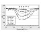
- FIG. 2is a graph showing the relationship between the incident light wavelength and the transmittance (I / I 0 ) (hereinafter sometimes referred to as the transmittance characteristic), showing the transmittance characteristic depending on the NO 2 concentration in N 2 gas. Shows the difference.
- the graphshows the transmittance characteristics for A1 to A5 in the cases where the NO 2 concentration is 0.74%, 2.22%, 3.70%, 7.39%, and 14.8%, respectively. .
- the transmittance valueis 1, the absorption by the gas does not occur in the measurement space and the absorbance is 0.
- the transmittance valueis 0, the gas is completely removed in the measurement space. It is absorbed and the concentration cannot be measured by absorbance.
- this graphis a graph when the gas pressure in the measurement space is 200 Torr.
- the peak wavelength of absorption of NO 2is near 405 nm, and for light with a wavelength of 405 nm, the transmittance is sufficient corresponding to the concentration in the concentration range of 0.74% to 14.8%. You can see that it is different. Therefore, when the NO 2 concentration is in the low concentration range (for example, 0 to 20%, particularly 0 to 15%), the concentration is measured from the absorbance according to the Lambert-Beer's law using light with a wavelength of 405 nm. You can see that it can be done properly.
- the transmittance (I / I 0 )becomes small when the concentration becomes relatively large, and the difference in the concentration becomes the transmittance or the absorbance in the higher concentration range. It can be inferred that it will be difficult to be reflected. Therefore, the accuracy of concentration measurement may be significantly reduced in the high concentration range. Further, especially in a region where the density is high, the transmittance may become a constant value of substantially 0, and the density may not be properly measured.
- the concentration measurementin the low concentration range, is performed using the light having a wavelength of 380 nm or more and 430 nm or less emitted from the first light emitting element, and in the high concentration range, the second measurement is performed.
- the concentrationis measured using light emitted from the light emitting element and having a wavelength of 500 nm to 550 nm. This makes it possible to widen the range in which concentration measurement can be performed appropriately.
- 3A and 3Bshow the relationship between the chamber internal pressure and the transmittance (I / I 0 ) when the NO 2 concentration was 100%, and the chamber internal pressure and the absorbance (-ln (I / I 0 )) and shows the case where the wavelength of the incident light is 405 nm and 525 nm in each graph.
- the transmittancewhen light with a wavelength of 405 nm having a high extinction coefficient is used, the transmittance can be accurately detected in the first pressure range (for example, 0 to 6 Torr), so that the concentration can be measured. It can be suitably performed. However, it can be seen that in the second pressure range (for example, 6 Torr or higher), the transmittance detection accuracy decreases, and the higher the pressure, the lower the detection accuracy. Note that FIG. 3B shows that the absorbance can be obtained by using the light having the wavelength of 405 nm even in the second pressure range, but in reality, the transmittance is almost high at the high pressure. Since it becomes 0, it is difficult to accurately obtain the absorbance.
- the transmittanceis too high in the first pressure range (that is, the absorbance is too small even at 100% concentration), so that it is difficult to accurately measure the concentration.
- the second pressure rangesince the accuracy of detecting the transmittance is good, the concentration can be appropriately detected.
- ln (I 0 / I)⁇ m ⁇ L ⁇ Pm / RT (where ⁇ m is the absorption coefficient of the absorbing gas, and R is the gas constant of the absorbing gas).
- Tcan guide the gas temperature).
- Cmln (I 0 / I) ⁇ (R ⁇ T) / ( ⁇ m ⁇ L ⁇ Pt), that is, the concentration Cm. Is dependent on the total pressure Pt and the temperature T.
- the concentration Cm of the light-absorbing gascan be obtained more accurately by performing correction based on the chamber internal pressure (total pressure) Pt and the gas temperature T measured using the pressure sensor 17 and the temperature sensor 18.
- the extinction coefficient ⁇ m of the light-absorbing gascan be obtained in advance by supplying the light-absorbing gas of a specified concentration and measuring the absorbance at the time of shipment, and the extinction coefficient ⁇ m is stored in the memory.
- the concentrationcan be read from the memory and used.
- FIG. 4shows various temperatures (20 ° C., 10 ° C., 5 ° C., 0 ° C., ⁇ 5 ° C., ⁇ 10 ° C., ⁇ 20 ° C., ⁇ 25 ° C., ⁇ 30 ° C.) when the concentration of TiCl 4 is 100%.
- 9is graphs T1 to T9 showing the transmittance characteristics in FIG. As can be seen from the graphs T1 to T9, TiCl 4 has absorption peak wavelengths near 230 nm and 285 nm. Further, it can be seen that at a temperature of ⁇ 30 ° C.
- the concentrationis measured using light having different wavelengths depending on the gas temperature. For example, when measuring the concentration of TiCl 4 gas at ⁇ 20 ° C. or lower, the concentration is measured using light with a wavelength of 280 nm or more and less than 300 nm having a high absorption coefficient, and the concentration of TiCl 4 gas at ⁇ 20 ° C. or higher is measured. At times, it is conceivable to perform concentration measurement using light having a wavelength of 300 nm or more and less than 340 nm, which has a lower absorption coefficient.
- FIG. 5is a graph showing the relationship between the pressure in the chamber and the transmittance (I / I 0 ) when the TiCl 4 concentration is 100%, and the wavelengths of incident light are 280 nm, 310 nm, 325 nm, and 340 nm, respectively. The graph of the time is shown.
- the transmittancewhen light with a wavelength of 280 to 310 nm having a high absorption coefficient is used, the transmittance can be accurately detected in the first pressure range (for example, 0 to 5 Torr), so that the concentration measurement is preferable. You can do it. However, it can be seen that in the second pressure range (5 Torr or more), the transmittance detection accuracy decreases, and the higher the pressure, the lower the detection accuracy. On the other hand, when light with a wavelength of 325 to 340 nm, which has a lower extinction coefficient, is used, the change of the transmittance is small in the first pressure range and it is difficult to measure the concentration, but the transmittance is detected in the second pressure range. Since the accuracy is good, the concentration can be properly detected.
- the first pressure rangefor example, 0 to 5 Torr
- the first light emitting element and the second light emitting elementare used to describe the mode of using incident light of two wavelengths, but three or more light emitting elements are used and any one of three or more wavelengths is used.
- the concentrationmay be measured by the light of. For example, when measuring the concentration of NO 2 , light having different wavelengths may be used in the low concentration region, the medium concentration region, and the high concentration region.
- concentration measuring device for measuring the gas concentration inside the chamber 10 of the semiconductor manufacturing apparatushas been described above, but an in-line type concentration measuring device may be used in another embodiment.
- the inline reflection-type density measuring device itselfis disclosed in, for example, Patent Document 2 (International Publication No. 2018/021311).
- FIG. 6shows a reflection-type measuring cell 30 used in the in-line reflection-type concentration measuring device 200.
- the measurement cell 30has an inflow port 30a, an outflow port 30b, and a vertically extending flow path 30c for the mixed gas G as a measurement fluid, and is incorporated in the middle of a gas supply line of a semiconductor manufacturing apparatus to supply the supply gas.
- the concentrationcan be measured.
- the flow path 30cserves as a measurement space for the measurement fluid.
- the measurement cell 30is provided with a translucent window portion (translucent plate) 31 that is in contact with the flow channel 30c and a reflecting member 32 that reflects incident light.
- a collimator 33 connected to an optical fiber 34is attached near the window 31.
- Light from a light source(not shown) is incident on the measurement cell 30 via the optical fiber 34 and reflected from the reflection member 32. Light can be received and guided to the photodetector.
- the light sourceis configured to be able to emit light of at least two wavelengths, as in the concentration measuring device 100 shown in FIG.
- the reflection-type concentration measuring device 200also includes a pressure sensor 17 and a temperature sensor 18 for detecting the pressure and temperature of the measurement fluid flowing in the measurement cell 30.
- the outputs of the pressure sensor 17 and the temperature sensor 18are connected to a calculation unit (not shown) via a sensor cable.
- the light source, the photodetector, and the calculation unit described aboveare provided as a concentration measurement unit at a position apart from the measurement cell 30, similarly to the concentration measurement device 100 shown in FIG.
- FIG. 7shows another embodiment of a two-core reflection-type concentration measuring device in which the measuring cell 30 and the concentration measuring unit 20 are connected by an incident side optical fiber 34a and an emitting side optical fiber 34b which are separately provided. Shows 300. Also in the reflection type concentration measuring device 300, the first light emitting element 22a and the second light emitting element 22b having different emission wavelengths are used as the light source, and the incident light is measured through the window portion 31 via the incident side optical fiber 34a. It is injected into the cell 30. Further, the reflected light from the reflecting member 32 passes through the window portion 31 and is input to the photodetector 24 via the emission side optical fiber 34b. By using separate optical fibers 34a and 34b like the reflection type concentration measuring device 300, the influence of stray light can be reduced.
- a light-emitting element having two or more wavelengthsis provided in the light source, and the emission wavelength is based on the gas concentration or gas temperature flowing inside the measurement cell (measurement space) By appropriately selecting, it is possible to perform concentration measurement with improved accuracy over a wider concentration range.
- the concentration measuring deviceis configured to allow incident light to enter from one end side of the measurement cell and to take out the measurement light from the other end side of the measurement cell without using a reflecting member.
- a transmission type in-line concentration measuring devicemay be used.
- the concentration measuring deviceis preferably used for measuring the concentration of a measurement fluid under various conditions.
Landscapes
- Physics & Mathematics (AREA)
- Chemical & Material Sciences (AREA)
- Health & Medical Sciences (AREA)
- Life Sciences & Earth Sciences (AREA)
- Spectroscopy & Molecular Physics (AREA)
- Biochemistry (AREA)
- General Health & Medical Sciences (AREA)
- General Physics & Mathematics (AREA)
- Immunology (AREA)
- Pathology (AREA)
- Analytical Chemistry (AREA)
- Engineering & Computer Science (AREA)
- Combustion & Propulsion (AREA)
- Food Science & Technology (AREA)
- Medicinal Chemistry (AREA)
- Mathematical Physics (AREA)
- Theoretical Computer Science (AREA)
- Toxicology (AREA)
- Investigating Or Analysing Materials By Optical Means (AREA)
- Optical Measuring Cells (AREA)
Abstract
Description
Translated fromJapanese本発明は、濃度測定装置に関し、特に、測定流体が流入する測定空間を透過した光の吸光度に基づいて、測定流体の濃度を測定するように構成された濃度測定装置に関する。The present invention relates to a concentration measuring device, and more particularly to a concentration measuring device configured to measure the concentration of a measuring fluid based on the absorbance of light transmitted through a measuring space into which the measuring fluid flows.
従来、例えば半導体製造装置に供給される有機金属(MO)等の液体材料や固体材料から形成された原料ガスの濃度を測定する濃度測定装置等が知られている。この種の濃度測定装置は、測定流体が流れる測定セルに、光入射窓を介して光源から所定波長の光を入射させ、測定セル内を通過した透過光を受光素子で受光することによって吸光度を測定するように構成されている。測定された吸光度からは、ランベルト・ベールの法則に従って測定流体の濃度を求めることができる(例えば、特許文献1または2)。Conventionally, for example, a concentration measuring device for measuring the concentration of a raw material gas formed from a liquid material such as an organic metal (MO) or a solid material supplied to a semiconductor manufacturing apparatus is known. This kind of concentration measuring device, the measurement cell through which the measurement fluid flows, the light of a predetermined wavelength from the light source is incident through the light entrance window, the transmitted light that has passed through the measurement cell is received by the light receiving element It is configured to measure. From the measured absorbance, the concentration of the measurement fluid can be determined according to the Lambert-Beer law (for example,
吸光度に基づいて測定流体中に含まれる所定流体の濃度を測定するためには、所定流体による吸光が比較的大きく生じる波長域の光を入射させることが求められる。吸光されにくい波長の光を用いた場合、所定流体の濃度の違いが吸光度に反映されにくく、濃度検出の精度は著しく低下する。In order to measure the concentration of the specified fluid contained in the measured fluid based on the absorbance, it is necessary to make light in the wavelength range in which absorption by the specified fluid relatively large occurs. When light having a wavelength that is difficult to be absorbed is used, it is difficult to reflect the difference in the concentration of the predetermined fluid in the absorbance, and the accuracy of concentration detection is significantly reduced.
しかしながら、本発明者の実験によれば、吸光度が大きすぎる波長の光を用いたときも、濃度測定が困難になる場合があることがわかった。このため、測定流体に適合する適切な波長の光を用いて濃度測定を適切に行うという課題があった。However, according to the experiments of the present inventor, it was found that the concentration measurement may be difficult even when using light having a wavelength whose absorbance is too large. Therefore, there has been a problem that the concentration measurement is appropriately performed using light having an appropriate wavelength suitable for the measurement fluid.
本発明は、上記課題を鑑みてなされたものであり、種々の測定流体に対して、吸光度に基づいて適切に濃度測定を行うことができる濃度測定装置を提供することをその主たる目的とする。The present invention has been made in view of the above problems, and its main object is to provide a concentration measuring device that can appropriately perform concentration measurement on various measurement fluids based on the absorbance.
本発明の実施形態による濃度測定装置は、測定流体が流入する測定空間と、前記測定空間に入射させる光を発する光源と、前記測定空間から出射した光を受け取る光検出器と、前記光検出器の出力に基づいて前記測定流体の濃度を演算する演算制御回路とを備え、前記演算制御回路は、前記光検出器の信号に基づいて、ランベルト・ベールの法則を利用して流体濃度を求めるように構成されている濃度測定装置であって、前記光源は、第1の波長の光を発生する第1の発光素子と、前記第1の波長とは異なる第2の波長の光を発生する第2の発光素子とを含み、前記測定流体の圧力または温度に基づいて、前記第1の波長の光または前記第2の波長の光のいずれかを用いて濃度を演算するように構成されている。A concentration measuring device according to an embodiment of the present invention includes a measurement space into which a measurement fluid flows, a light source that emits light to enter the measurement space, a photodetector that receives light emitted from the measurement space, and the photodetector. And a calculation control circuit for calculating the concentration of the measurement fluid based on the output of the photodetector, and the calculation control circuit obtains the concentration of the fluid by using the Lambert-Beer law based on the signal of the photodetector. In the concentration measuring device according to
ある実施形態において、上記の濃度測定装置は、前記測定空間における流体温度を測定する温度センサをさらに備え、前記温度センサの出力に基づいて前記濃度を補正するように構成されている。In one embodiment, the concentration measuring device further includes a temperature sensor that measures the fluid temperature in the measurement space, and is configured to correct the concentration based on the output of the temperature sensor.
ある実施形態において、上記の濃度測定装置は、前記測定空間における流体圧力を測定する圧力センサをさらに備え、前記圧力センサの出力に基づいて前記濃度を補正するように構成されている。In one embodiment, the concentration measuring device further includes a pressure sensor that measures the fluid pressure in the measurement space, and is configured to correct the concentration based on the output of the pressure sensor.
本発明の実施形態によれば、測定流体の状態に応じて適切に濃度測定を実行することができる。According to the embodiment of the present invention, the concentration measurement can be appropriately performed according to the state of the measurement fluid.
以下、図面を参照しながら本発明の実施形態を説明するが、本発明は以下の実施形態に限定されるものではない。Hereinafter, embodiments of the present invention will be described with reference to the drawings, but the present invention is not limited to the following embodiments.
図1は、本実施形態の濃度測定装置100の構成例を示す図である。濃度測定装置100は、半導体製造装置(例えばプラズマCVD装置)のチャンバ10の内部(測定空間10A)に流入した流体の濃度を測定するように構成されている。FIG. 1 is a diagram showing a configuration example of the
チャンバ10の内部には、半導体デバイス用のウェハを載置するためのサセプタ12と、サセプタ12の上方(ガス導入管側)に配置されたシャワープレート14とが設けられている。シャワープレート14とサセプタ12とは、所定の間隙を開けて平行に配置されている。また、シャワープレート14には、流体が通過する多数の孔が形成されており、チャンバ10に導入されたガスは、シャワープレート14によって拡散されて、ウェハ上により均一に供給される。また、サセプタ12の下方において、チャンバ10には排気管および真空ポンプ16が設けられており、チャンバ10内の余剰ガスは排気される。真空ポンプ16は、チャンバ10内を真空引きするためにも用いられる。Inside the
また、チャンバ10には、圧力センサ17および温度センサ18が取り付けられており、チャンバ10内の流体の圧力および温度を測定することができる。Further, a
チャンバ10にガスを供給するためのガス供給部1は、本実施形態では、NO2ガスソース2aと、N2ガスソース2bとを含んでおり、それぞれのガスラインが途中で合流し、NO2ガスとN2ガスとの混合ガスGがチャンバ10に供給されるように構成されている。また、各ガスラインには流量制御装置3が設けられており、各ガスの流量を調整することによって所望の混合比(またはNO2濃度)の混合ガスGを供給することができる。NO2ガスの流量は例えば3.7sccmに設定され、N2ガスの流量は例えば100sccmに設定される。流量制御装置3としては、例えば、特許文献3に記載の公知の圧力式流量制御装置を用いることができる。圧力式流量制御装置は、絞り部と制御弁とを有しており、絞り部の上流側圧力に基づいて制御弁の開度を調整することによって流量を制御するように構成されている。
濃度測定装置100は、チャンバ10内の測定空間10Aに流入した混合ガス中のNO2濃度を、吸光度に基づいて測定するように構成されている。このために、濃度測定装置100は、チャンバ10の一方の側部からチャンバ10内に光を入射させるための入射側光ファイバ21aと、チャンバ10の他方の側部から出射した光を導光するための出射側光ファイバ21bと、入射側光ファイバ21aおよび出射側光ファイバ21bに接続された濃度測定ユニット20とを備えている。濃度測定ユニット20は、使用している部品や基板等の耐熱温度の関係もあり、チャンバ10から離れた場所に配置され、チャンバ10内が高温になったときにも、温度の影響によって破損・誤動作が生じないようになっている。The
なお、本明細書において、光とは、可視光線のみならず、少なくとも赤外線、紫外線を含み、任意の波長の電磁波を含み得る。また、透光性とは、測定空間10Aに入射させる前記の光に対する内部透過率が濃度測定を行い得る程度に十分に高いことを意味する。In the present specification, the light includes not only visible light but also at least infrared rays and ultraviolet rays, and may include electromagnetic waves of any wavelength. Further, the light-transmitting property means that the internal transmittance for the light incident on the
入射側光ファイバ21aは、チャンバ10の一方の側に接続され、チャンバ10の側壁に設けられた透光性の入射側窓部11aを介して、濃度測定ユニット20からの入射光を測定空間10Aに入射させる。また、出射側光ファイバ21bは、チャンバ10の他方の側に接続され、チャンバ10の側壁に設けられた透光性の出射側窓部11bを介して、測定空間10Aからの検出光を受け取り、濃度測定ユニット20に導光する。The incident-side
入射側窓部11aと出射側窓部11bとは、シャワープレート14とサセプタ12との間を光が通過するように、測定空間10Aを挟んで対向するように配置されている。また、濃度測定装置100は、入射側光ファイバ21aに接続された入射側窓部11aの近傍のコリメータと、出射側光ファイバ21bに接続された出射側窓部11bの近傍のコリメータとを有し、測定空間10Aを平行光が通過するように構成されている。入射側窓部11aと出射側窓部11bとの距離、すなわち、測定空間10Aを通過する光の光路長は、例えば、200mm~300mmに設定される。The
上記のように光ファイバ21a、21bによってチャンバ10と接続された濃度測定ユニット20は、測定空間10Aに入射させる光を発生する光源22と、測定空間10Aから出射した光の強度を測定する光検出器24と、光源22および光検出器24に接続された演算制御回路26とを有している。光検出器24を構成する受光素子としては、例えばフォトダイオードやフォトトランジスタが好適に用いられる。As described above, the
光源22は、それぞれ異なる波長の光を発する第1発光素子22aと第2発光素子22bとを備えており、本実施形態では、第1および第2発光素子はLEDである。第1発光素子22aおよび第2発光素子22bは、ハーフミラー22cに向けて光を出射するように取り付けられており、いずれの発光素子22a、22bからの光も、入射側光ファイバ21aを介して測定空間10A内に入射させることができる。The
また、光源22は、第1発光素子22aおよび第2発光素子22bから、2つの波長の光をパルス状に交互に出力するように構成されていても良いし、2波長の光を同時に出力するように構成されていてもよい。2波長の光を同時に出力する場合、WDM(波長分割多重方式)の合波器により2波長の光を合成するとともに、第1発光素子22aおよび第2発光素子22bには、発振回路を用いて異なる周波数の駆動電流が流される。このように異なる周波数で各発光素子を駆動することにより、後に、周波数解析(例えば、高速フーリエ変換やウェーブレット変換)を行って、光検出器24が検出した検出信号から、各波長成分に対応した光の強度ひいては吸光度を測定することができる。また、光源22は、測定流体の濃度が特定の濃度になった時点で第1発光素子22aおよび第2発光素子22bのいずれを発光させるかを切り替えるように構成されていてもよい。Further, the
演算制御回路26は、光源22に接続された光源制御部27と、光検出器24に接続された濃度演算部28とを有している。光源制御部27は、上記の第1発光素子22aと第2発光素子22bとの発光を制御することができる。また、濃度演算部28は、光検出器24の検出信号に基づいて測定流体の濃度を演算することができる。The
演算制御回路26は、例えば、回路基板上に設けられたプロセッサやメモリなどによって構成され、入力信号に基づいて所定の演算を実行するコンピュータプログラムを含み、ハードウェアとソフトウェアとの組み合わせによって実現され得る。The
以上のように構成された濃度測定装置100において、演算制御回路26の濃度演算部28は、光検出器24からの検出信号に基づいて波長λにおける吸光度Aλ(-log10(I/I0))を求めることができ、また、以下の式(1)に示すランベルト・ベールの法則に基づいて、ガス濃度Cを算出することができる。
Aλ=-log10(I/I0)=αLC ・・・(1)In the
Aλ = −log10 (I / I0 ) = αLC (1)
上記の式(1)において、I0は測定空間に入射する入射光の強度、Iは測定空間を通過した光の強度、αはモル吸光係数(m2/mol)、Lは測定空間内の光路長(m)、Cは濃度(mol/m3)である。モル吸光係数αは物質によって決まる係数である。In the above formula (1), I0 is the intensity of incident light that enters the measurement space, I is the intensity of light that has passed through the measurement space, α is the molar extinction coefficient (m2 / mol), and L is the inside of the measurement space. Optical path length (m) and C are concentrations (mol / m3 ). The molar extinction coefficient α is a coefficient determined by the substance.
なお、上記式における入射光強度I0は、測定空間10Aに吸光性のガスが存在しないとき(例えば、吸光性を有しないパージガスが充満しているときや、真空に引かれているとき)に光検出器24によって検出された光の強度であってよい。It should be noted that the incident light intensity I0 in the above equation is obtained when there is no light-absorbing gas in the
以下、濃度測定に用いる光源22の詳細について説明する。上述したように、光源22は、第1発光素子22aと、第2発光素子22bとを備えている。本実施形態では、第1発光素子22aが発する光の波長は405nmであり、第2発光素子22bが発する光の波長は525nmである。そして、光源22を制御する光源制御部27は、第1発光素子22aまたは第2発光素子22bのいずれかを発光させ、405nmまたは525nmのいずれかの波長の光を測定空間10Aに入射させることができるように構成されている。いずれの波長の光を用いるかは、例えば、測定対象のガスの濃度域によって適宜選択される。The details of the
図2は、入射光波長と透過率(I/I0)との関係(以下、透過率特性と呼ぶことがある)を示すグラフであり、N2ガス中のNO2濃度による透過率特性の違いを示している。グラフには、NO2濃度が、0.74%、2.22%、3.70%、7.39%、14.8%のそれぞれの場合A1~A5について、透過率特性が示されている。なお、透過率の値が1である場合、測定空間中においてガスによる吸光は生じておらず吸光度が0であり、一方、透過率の値が0である場合、測定空間中においてガスが完全に吸光され、吸光度による濃度の測定が不可能である。また、本グラフは、測定空間内のガス圧力が200Torrの時のグラフである。FIG. 2 is a graph showing the relationship between the incident light wavelength and the transmittance (I / I0 ) (hereinafter sometimes referred to as the transmittance characteristic), showing the transmittance characteristic depending on the NO2 concentration in N2 gas. Shows the difference. The graph shows the transmittance characteristics for A1 to A5 in the cases where the NO2 concentration is 0.74%, 2.22%, 3.70%, 7.39%, and 14.8%, respectively. . In addition, when the transmittance value is 1, the absorption by the gas does not occur in the measurement space and the absorbance is 0. On the other hand, when the transmittance value is 0, the gas is completely removed in the measurement space. It is absorbed and the concentration cannot be measured by absorbance. Further, this graph is a graph when the gas pressure in the measurement space is 200 Torr.
図2から、NO2の吸光のピーク波長は405nm近傍であり、405nmの波長の光に対しては、0.74%~14.8%の濃度範囲において、濃度に対応して透過率が十分に異なることが分かる。このため、NO2の濃度が低濃度域(例えば0~20%、特には0~15%)のときには、405nmの波長の光を用いて、ランベルト・ベールの法則に従って、吸光度から濃度の測定を適切に行えることがわかる。From FIG. 2, the peak wavelength of absorption of NO2 is near 405 nm, and for light with a wavelength of 405 nm, the transmittance is sufficient corresponding to the concentration in the concentration range of 0.74% to 14.8%. You can see that it is different. Therefore, when the NO2 concentration is in the low concentration range (for example, 0 to 20%, particularly 0 to 15%), the concentration is measured from the absorbance according to the Lambert-Beer's law using light with a wavelength of 405 nm. You can see that it can be done properly.
しかしながら、濃度14.8%のグラフA5からわかるように、濃度が比較的大きくなると、透過率(I/I0)は小さいものとなり、より高濃度域では、濃度の差が透過率または吸光度に反映されにくくなることが推察できる。したがって、高濃度域では濃度測定の精度が著しく低下し得る。また、特に濃度が大きい領域では、透過率が略0の一定の値となって濃度測定が適切に行えない可能性が生じる。したがって、より高濃度域の測定を行うときには、吸収係数が高い波長(405nm)からずらした、より吸光されにくい、すなわち吸光係数が低い波長(525nm)の光を用いた方が、濃度測定の精度を向上させることができる。However, as can be seen from the graph A5 of the concentration of 14.8%, the transmittance (I / I0 ) becomes small when the concentration becomes relatively large, and the difference in the concentration becomes the transmittance or the absorbance in the higher concentration range. It can be inferred that it will be difficult to be reflected. Therefore, the accuracy of concentration measurement may be significantly reduced in the high concentration range. Further, especially in a region where the density is high, the transmittance may become a constant value of substantially 0, and the density may not be properly measured. Therefore, when performing measurement in a higher concentration range, it is better to use light with a wavelength (525 nm) that is more difficult to be absorbed, that is, shifted from a wavelength with a higher absorption coefficient (405 nm), that is, the accuracy of concentration measurement. Can be improved.
このため、本実施形態では、NO2の濃度測定において、低濃度域のときには、第1発光素子が発する380nm以上430nm以下の波長の光を用いて濃度測定を行い、高濃度域のときには第2発光素子が発する500nm以上550nmの波長の光を用いて濃度測定を行うようにしている。これによって、適切に濃度測定を行える範囲を広げることが可能になる。Therefore, in the present embodiment, in the NO2 concentration measurement, in the low concentration range, the concentration measurement is performed using the light having a wavelength of 380 nm or more and 430 nm or less emitted from the first light emitting element, and in the high concentration range, the second measurement is performed. The concentration is measured using light emitted from the light emitting element and having a wavelength of 500 nm to 550 nm. This makes it possible to widen the range in which concentration measurement can be performed appropriately.
また、図3(a)および(b)は、NO2濃度100%のときの、チャンバ内圧力と透過率(I/I0)との関係、および、チャンバ内圧力と吸光度(-ln(I/I0))との関係を示すグラフであり、それぞれのグラフにおいて入射光の波長が405nmの場合と525nmの場合とを示している。3A and 3B show the relationship between the chamber internal pressure and the transmittance (I / I0 ) when the NO2 concentration was 100%, and the chamber internal pressure and the absorbance (-ln (I / I0 )) and shows the case where the wavelength of the incident light is 405 nm and 525 nm in each graph.
図3(a)からわかるように、吸光係数が高い405nmの波長の光を用いた場合、第1の圧力域(例えば0~6Torr)において、透過率の検出が精度よく行えるので、濃度測定が好適に行える。ただし、第2の圧力域(例えば6Torr以上)では、透過率の検出精度が低下し、圧力がより高いほど検出精度が低下することがわかる。なお、図3(b)では、第2の圧力域のときにも波長405nmの光を用いて吸光度が求められ得ることが示されているが、実際には、高圧力のときには透過率がほとんど0になるため、正確に吸光度を求めることは困難である。As can be seen from FIG. 3 (a), when light with a wavelength of 405 nm having a high extinction coefficient is used, the transmittance can be accurately detected in the first pressure range (for example, 0 to 6 Torr), so that the concentration can be measured. It can be suitably performed. However, it can be seen that in the second pressure range (for example, 6 Torr or higher), the transmittance detection accuracy decreases, and the higher the pressure, the lower the detection accuracy. Note that FIG. 3B shows that the absorbance can be obtained by using the light having the wavelength of 405 nm even in the second pressure range, but in reality, the transmittance is almost high at the high pressure. Since it becomes 0, it is difficult to accurately obtain the absorbance.
一方、吸光係数がより低い525nmの波長の光を用いた場合、第1の圧力域では透過率が高すぎる(すなわち、100%濃度でも吸光度が小さすぎる)ので、濃度測定を精度よく行いにくい。ただし、第2の圧力域では、透過率の検出精度が良好であるので、濃度検出も適切に行うことができる。On the other hand, when light with a wavelength of 525 nm, which has a lower extinction coefficient, is used, the transmittance is too high in the first pressure range (that is, the absorbance is too small even at 100% concentration), so that it is difficult to accurately measure the concentration. However, in the second pressure range, since the accuracy of detecting the transmittance is good, the concentration can be appropriately detected.
以上の結果から、測定対象が高濃度域でガス圧力が比較的高いときの濃度測定には、525nmの波長の光を用いることが好適であることがわかる。また、低濃度域、あるいは、高濃度域であってもガス圧力が比較的低いときには、405nmの波長の光を用いることが好適であることがわかる。From the above results, it can be seen that it is preferable to use light with a wavelength of 525 nm for concentration measurement when the measurement target is in a high concentration range and the gas pressure is relatively high. Further, it is understood that it is preferable to use light having a wavelength of 405 nm when the gas pressure is relatively low even in the low concentration region or the high concentration region.
なお、実際に測定できるチャンバ内圧力は、測定対象のガス成分(吸光ガス)およびキャリアガスを含む混合ガスの全圧Ptを示しており、測定対象のガスの分圧をPmとし、その濃度をCmとすると、Pm=Pt・Cmと表すことができる。また、理想気体の状態方程式およびランベルト・ベールの式からln(I0/I)=αm・L・Pm/RT(ただし、αmは、吸光ガスの吸光係数、Rは吸光ガスの気体定数、Tはガス温度)を導くことができる。さらに、上記の式から分圧Pmを消去するように式変形を行うと、Cm=ln(I0/I)・(R・T)/(αm・L・Pt)となり、すなわち、濃度Cmは、全圧Ptおよび温度Tに依存することがわかる。The chamber pressure that can be actually measured indicates the total pressure Pt of the mixed gas containing the gas component (absorption gas) to be measured and the carrier gas, and the partial pressure of the gas to be measured is Pm, and its concentration is If Cm, it can be expressed as Pm = Pt · Cm. Further, from the ideal gas equation of state and the Lambert-Beer equation, ln (I0 / I) = αm · L · Pm / RT (where αm is the absorption coefficient of the absorbing gas, and R is the gas constant of the absorbing gas). , T can guide the gas temperature). Further, when the formula is modified from the above formula so as to eliminate the partial pressure Pm, Cm = ln (I0 / I) · (R · T) / (αm · L · Pt), that is, the concentration Cm. Is dependent on the total pressure Pt and the temperature T.
したがって、圧力センサ17および温度センサ18を用いて測定したチャンバ内圧力(全圧)Ptおよびガス温度Tに基づいて補正を行うことによって、より正確に吸光ガスの濃度Cmを求めることができる。なお、吸光ガスの吸光係数αmは、出荷時等に、規定濃度の吸光ガスを供給するとともに吸光度を測定することによって予め求めておくことができ、吸光係数αmをメモリに格納しておくことにより、濃度測定の際にはメモリから読み出して用いることができる。Therefore, the concentration Cm of the light-absorbing gas can be obtained more accurately by performing correction based on the chamber internal pressure (total pressure) Pt and the gas temperature T measured using the
次に、TiCl4の濃度測定を行う場合について説明する。図4は、TiCl4の濃度が100%の場合における、各温度(20℃、10℃、5℃、0℃、-5℃、-10℃、-20℃、-25℃、-30℃)での透過率特性を示すグラフT1~T9である。グラフT1~T9からわかるように、TiCl4は、230nmおよび285nmの近傍に吸光ピーク波長を有している。また、-30℃~20℃の温度では、温度が高いほど吸光の程度が大きくなることがわかる。特に、グラフT1~T6に示されるように、-10℃以上の温度では、280nmの光を用いると透過率が0となり、100%近辺の高濃度域では濃度測定が困難になることがわかる。Next, the case of measuring the concentration of TiCl4 will be described. FIG. 4 shows various temperatures (20 ° C., 10 ° C., 5 ° C., 0 ° C., −5 ° C., −10 ° C., −20 ° C., −25 ° C., −30 ° C.) when the concentration of TiCl4 is 100%. 9 is graphs T1 to T9 showing the transmittance characteristics in FIG. As can be seen from the graphs T1 to T9, TiCl4 has absorption peak wavelengths near 230 nm and 285 nm. Further, it can be seen that at a temperature of −30 ° C. to 20 ° C., the higher the temperature, the greater the degree of light absorption. In particular, as shown in the graphs T1 to T6, it can be seen that at a temperature of −10 ° C. or higher, the transmittance becomes 0 when light of 280 nm is used, and it becomes difficult to measure the concentration in the high concentration range around 100%.
このため、ガス温度に応じて異なる波長の光を用いて濃度測定を行うことが考えられる。例えば、-20℃以下のTiCl4ガスの濃度を測定するときには、吸光係数が高い280nm以上300nm未満の波長の光を用いて濃度測定を行い、-20℃以上のTiCl4ガスの濃度を測定するときには、吸光係数がより低い300nm以上340nm未満の波長の光を用いて濃度測定を行うことが考えられる。Therefore, it is conceivable to measure the concentration using light having different wavelengths depending on the gas temperature. For example, when measuring the concentration of TiCl4 gas at −20 ° C. or lower, the concentration is measured using light with a wavelength of 280 nm or more and less than 300 nm having a high absorption coefficient, and the concentration of TiCl4 gas at −20 ° C. or higher is measured. At times, it is conceivable to perform concentration measurement using light having a wavelength of 300 nm or more and less than 340 nm, which has a lower absorption coefficient.
図5は、TiCl4濃度100%のときの、チャンバ内圧力と透過率(I/I0)との関係を示すグラフであり、入射光の波長が、280nm、310nm、325nm、340nmのそれぞれのときのグラフが示されている。FIG. 5 is a graph showing the relationship between the pressure in the chamber and the transmittance (I / I0 ) when the TiCl4 concentration is 100%, and the wavelengths of incident light are 280 nm, 310 nm, 325 nm, and 340 nm, respectively. The graph of the time is shown.
図5からわかるように、吸光係数が高い280~310nmの波長の光を用いた場合、第1の圧力域(例えば0~5Torr)において、透過率の検出が精度よく行えるので、濃度測定が好適に行える。ただし、第2の圧力域(5Torr以上)では、透過率の検出精度が低下し、圧力がより高いほど検出精度が低下することがわかる。一方、吸光係数がより低い325~340nmの波長の光を用いた場合、第1の圧力域では透過率の変化が小さく、濃度測定を行いにくいが、第2の圧力域では、透過率の検出精度が良好であるので、濃度検出を適切に行うことができる。As can be seen from FIG. 5, when light with a wavelength of 280 to 310 nm having a high absorption coefficient is used, the transmittance can be accurately detected in the first pressure range (for example, 0 to 5 Torr), so that the concentration measurement is preferable. You can do it. However, it can be seen that in the second pressure range (5 Torr or more), the transmittance detection accuracy decreases, and the higher the pressure, the lower the detection accuracy. On the other hand, when light with a wavelength of 325 to 340 nm, which has a lower extinction coefficient, is used, the change of the transmittance is small in the first pressure range and it is difficult to measure the concentration, but the transmittance is detected in the second pressure range. Since the accuracy is good, the concentration can be properly detected.
以上の結果から、低温でガス圧力が比較的大きいときの濃度測定には、325~340nmの波長の光を用いることが好適であることがわかる。また、高温、あるいは、低温であっても、ガス圧力が比較的低いときには、280~310nmの波長の光を用いることが好適であることがわかる。From the above results, it can be seen that it is preferable to use light with a wavelength of 325 to 340 nm for the concentration measurement when the gas pressure is relatively high at a low temperature. Further, it is found that it is preferable to use light having a wavelength of 280 to 310 nm even when the gas pressure is relatively low, even at high temperature or low temperature.
以上、本発明の実施形態を説明したが、種々の改変が可能である。例えば、上記には第1発光素子および第2発光素子を用いて、2つの波長の入射光を用いる態様を説明したが、3つ以上の発光素子を用いて、3つ以上の波長のいずれかの光によって濃度測定を行うようにしてもよい。例えば、NO2の濃度測定を行う場合、低濃度域、中濃度域、高濃度域のそれぞれで異なる波長の光を用いるようにしてもよい。The embodiments of the present invention have been described above, but various modifications are possible. For example, in the above description, the first light emitting element and the second light emitting element are used to describe the mode of using incident light of two wavelengths, but three or more light emitting elements are used and any one of three or more wavelengths is used. The concentration may be measured by the light of. For example, when measuring the concentration of NO2 , light having different wavelengths may be used in the low concentration region, the medium concentration region, and the high concentration region.
また、上記には、半導体製造装置のチャンバ10の内部におけるガス濃度を測定する濃度測定装置を説明したが、他の実施形態において、インライン式の濃度測定装置であってもよい。なお、インライン式の反射型濃度測定装置自体は、例えば、特許文献2(国際公開第2018/021311号)に開示されている。Further, the concentration measuring device for measuring the gas concentration inside the
図6は、インライン式の反射型濃度測定装置200に用いられる反射型の測定セル30を示す。測定セル30は、測定流体である混合ガスGの流入口30a、流出口30b、および垂直方向に延びる流路30cを有し、半導体製造装置のガス供給ラインの途中に組み込まれて、供給ガスの濃度を測定することができる。本実施形態では、流路30cが、測定流体の測定空間となる。FIG. 6 shows a reflection-
測定セル30には、流路30cに接する透光性の窓部(透光性プレート)31および入射光を反射させる反射部材32が設けられている。窓部31の近傍には、光ファイバ34に接続されたコリメータ33が取り付けられており、光ファイバ34を介して図示しない光源からの光を測定セル30に入射させるとともに、反射部材32からの反射光を受光して光検出器へと導光することができる。本実施形態においても、光源は、図1に示した濃度測定装置100と同様に、少なくとも2波長の光を出射することができるように構成されている。The
また、反射型濃度測定装置200は、測定セル30内を流れる測定流体の圧力および温度を検出するための圧力センサ17および温度センサ18を備えている。圧力センサ17および温度センサ18の出力は、センサケーブルを介して図示しない演算部に接続されている。なお、上記の光源、光検出器、演算部は、図1に示した濃度測定装置100と同様に、測定セル30から離れた位置に濃度測定ユニットとして設けられている。The reflection-type
また、図7は、測定セル30と濃度測定ユニット20とを、別個に設けた入射側光ファイバ34aと出射側光ファイバ34bとによって接続する、他の態様の二芯式の反射型濃度測定装置300を示す。反射型濃度測定装置300においても、光源として発光波長の異なる第1発光素子22aと第2発光素子22bとが用いられており、入射光は入射側光ファイバ34aを介して窓部31を通り測定セル30内に入射される。また、反射部材32からの反射光は、窓部31を通り出射側光ファイバ34bを介して光検出器24に入力される。反射型濃度測定装置300のように別個の光ファイバ34a、34bを用いることによって、迷光の影響を低減し得る。Further, FIG. 7 shows another embodiment of a two-core reflection-type concentration measuring device in which the measuring
以上に説明したインライン式の反射型濃度測定装置200、300においても、光源に2波長以上の発光素子を設けて、測定セル(測定空間)の内部を流れるガス濃度やガス温度に基づいて発光波長を適切に選択することで、より広い濃度範囲にわたって精度の向上した濃度測定を行うことができる。Also in the inline-type reflection-type
また、本発明の他の実施形態による濃度測定装置は、反射部材を用いることなく、測定セルの一端側から入射光を入射させ、測定セルの他端側から測定光を取り出すように構成された透過型のインライン式の濃度測定装置であってもよい。Further, the concentration measuring device according to another embodiment of the present invention is configured to allow incident light to enter from one end side of the measurement cell and to take out the measurement light from the other end side of the measurement cell without using a reflecting member. A transmission type in-line concentration measuring device may be used.
本発明の実施形態にかかる濃度測定装置は、種々の条件の測定流体の濃度を測定するために好適に用いられる。The concentration measuring device according to the embodiment of the present invention is preferably used for measuring the concentration of a measurement fluid under various conditions.
1 ガス供給部
2a NO2ガスソース
2b N2ガスソース
3 流量制御装置
10 チャンバ
10A 測定空間
12 サセプタ
14 シャワープレート
16 真空ポンプ
17 圧力センサ
18 温度センサ
20 濃度測定ユニット
21a 入射側光ファイバ
21b 出射側光ファイバ
22 光源
22a 第1発光素子
22b 第2発光素子
24 光検出器
26 演算制御回路
27 光源制御部
28 濃度演算部
30 測定セル
31 窓部
32 反射部材1
Claims (3)
Translated fromJapanese前記光源は、第1の波長の光を発生する第1の発光素子と、前記第1の波長とは異なる第2の波長の光を発生する第2の発光素子とを含み、前記測定流体の圧力または温度に基づいて、前記第1の波長の光または前記第2の波長の光のいずれかを用いて濃度を測定するように構成されている、濃度測定装置。A measurement space into which a measurement fluid flows, a light source that emits light to be incident on the measurement space, a photodetector that receives light emitted from the measurement space, and a concentration of the measurement fluid based on the output of the photodetector. A concentration measuring device comprising: a calculation control circuit obtained by calculation, wherein the calculation control circuit is configured to obtain a concentration based on a signal of the photodetector by using Lambert-Beer's law. ,
The light source includes a first light emitting element that emits light of a first wavelength and a second light emitting element that emits light of a second wavelength different from the first wavelength. A concentration measuring device configured to measure the concentration using either the light of the first wavelength or the light of the second wavelength based on pressure or temperature.
Priority Applications (4)
| Application Number | Priority Date | Filing Date | Title |
|---|---|---|---|
| JP2020553343AJP7323945B2 (en) | 2018-10-26 | 2019-10-18 | Concentration measurement method |
| KR1020217009231AKR102498481B1 (en) | 2018-10-26 | 2019-10-18 | concentration measuring device |
| CN201980065598.3ACN112805551A (en) | 2018-10-26 | 2019-10-18 | Concentration measuring device |
| US17/288,300US11686671B2 (en) | 2018-10-26 | 2019-10-18 | Concentration measurement device |
Applications Claiming Priority (2)
| Application Number | Priority Date | Filing Date | Title |
|---|---|---|---|
| JP2018201838 | 2018-10-26 | ||
| JP2018-201838 | 2018-10-26 |
Publications (1)
| Publication Number | Publication Date |
|---|---|
| WO2020085236A1true WO2020085236A1 (en) | 2020-04-30 |
Family
ID=70331399
Family Applications (1)
| Application Number | Title | Priority Date | Filing Date |
|---|---|---|---|
| PCT/JP2019/041107CeasedWO2020085236A1 (en) | 2018-10-26 | 2019-10-18 | Concentration measurement device |
Country Status (6)
| Country | Link |
|---|---|
| US (1) | US11686671B2 (en) |
| JP (1) | JP7323945B2 (en) |
| KR (1) | KR102498481B1 (en) |
| CN (1) | CN112805551A (en) |
| TW (1) | TWI734226B (en) |
| WO (1) | WO2020085236A1 (en) |
Cited By (1)
| Publication number | Priority date | Publication date | Assignee | Title |
|---|---|---|---|---|
| US20240241042A1 (en)* | 2021-05-12 | 2024-07-18 | Tokyo Electron Limited | Substrate processing device and method for measuring process gas temperature and concentration |
Families Citing this family (1)
| Publication number | Priority date | Publication date | Assignee | Title |
|---|---|---|---|---|
| US20230168192A1 (en)* | 2021-11-29 | 2023-06-01 | Asahi Kasei Microdevices Corporation | Concentration measurement apparatus and concentration measurement method |
Citations (4)
| Publication number | Priority date | Publication date | Assignee | Title |
|---|---|---|---|---|
| JP2011021996A (en)* | 2009-07-15 | 2011-02-03 | Nippon Soken Inc | Gas concentration measuring instrument |
| JP2013050403A (en)* | 2011-08-31 | 2013-03-14 | Shimadzu Corp | Gas analyzer |
| US20150136961A1 (en)* | 2013-11-21 | 2015-05-21 | TOTAL Gas Detection Ltd. | Methods and Devices for Analyzing Gases in Well-Related Fluids Using Fourier Transform Infrared (FTIR) Spectroscopy |
| WO2016047168A1 (en)* | 2014-09-22 | 2016-03-31 | 株式会社 東芝 | Gas analyzer and gas processing apparatus |
Family Cites Families (12)
| Publication number | Priority date | Publication date | Assignee | Title |
|---|---|---|---|---|
| JPH09318528A (en)* | 1996-05-28 | 1997-12-12 | Matsushita Electric Works Ltd | Gas sensor |
| JP4669193B2 (en) | 2002-10-16 | 2011-04-13 | 忠弘 大見 | Temperature measuring device for pressure flow control device |
| EP1586674A1 (en)* | 2004-04-14 | 2005-10-19 | Nederlandse Organisatie voor Toegepast-Natuuurwetenschappelijk Onderzoek TNO | Coatings, and methods and devices for the manufacture thereof |
| JP2009041941A (en)* | 2007-08-06 | 2009-02-26 | Fuji Electric Systems Co Ltd | Gas concentration measuring device and gas concentration measuring method |
| JP5943352B2 (en)* | 2010-11-16 | 2016-07-05 | 株式会社日立製作所 | Biological light measurement device and its operation method |
| JP5885699B2 (en) | 2013-05-09 | 2016-03-15 | 株式会社フジキン | Fixing structure of brittle destructible light transmitting window plate and fixing method of brittle destructible light transmitting window plate using the same |
| JP5973969B2 (en)* | 2013-07-31 | 2016-08-23 | 国立大学法人徳島大学 | Inline densitometer and concentration detection method |
| WO2016080532A1 (en) | 2014-11-23 | 2016-05-26 | 株式会社フジキン | Optical gas concentration measurement method, and method for monitoring gas concentration by such method |
| AT518433B1 (en)* | 2016-04-18 | 2017-10-15 | Scan Messtechnik Ges Mbh | Spectrometer and method for assaying the ingredients of a fluid |
| JP6912766B2 (en) | 2016-07-29 | 2021-08-04 | 国立大学法人徳島大学 | Concentration measuring device |
| JP6786099B2 (en)* | 2016-08-12 | 2020-11-18 | 株式会社フジキン | Concentration measuring device |
| DE202017001743U1 (en)* | 2017-03-31 | 2017-05-08 | Siemens Aktiengesellschaft | Gas analyzer |
- 2019
- 2019-10-18WOPCT/JP2019/041107patent/WO2020085236A1/ennot_activeCeased
- 2019-10-18JPJP2020553343Apatent/JP7323945B2/enactiveActive
- 2019-10-18KRKR1020217009231Apatent/KR102498481B1/enactiveActive
- 2019-10-18USUS17/288,300patent/US11686671B2/enactiveActive
- 2019-10-18CNCN201980065598.3Apatent/CN112805551A/enactivePending
- 2019-10-22TWTW108137985Apatent/TWI734226B/enactive
Patent Citations (4)
| Publication number | Priority date | Publication date | Assignee | Title |
|---|---|---|---|---|
| JP2011021996A (en)* | 2009-07-15 | 2011-02-03 | Nippon Soken Inc | Gas concentration measuring instrument |
| JP2013050403A (en)* | 2011-08-31 | 2013-03-14 | Shimadzu Corp | Gas analyzer |
| US20150136961A1 (en)* | 2013-11-21 | 2015-05-21 | TOTAL Gas Detection Ltd. | Methods and Devices for Analyzing Gases in Well-Related Fluids Using Fourier Transform Infrared (FTIR) Spectroscopy |
| WO2016047168A1 (en)* | 2014-09-22 | 2016-03-31 | 株式会社 東芝 | Gas analyzer and gas processing apparatus |
Cited By (1)
| Publication number | Priority date | Publication date | Assignee | Title |
|---|---|---|---|---|
| US20240241042A1 (en)* | 2021-05-12 | 2024-07-18 | Tokyo Electron Limited | Substrate processing device and method for measuring process gas temperature and concentration |
Also Published As
| Publication number | Publication date |
|---|---|
| KR20210048542A (en) | 2021-05-03 |
| JPWO2020085236A1 (en) | 2021-09-16 |
| KR102498481B1 (en) | 2023-02-10 |
| CN112805551A (en) | 2021-05-14 |
| US20210396657A1 (en) | 2021-12-23 |
| TWI734226B (en) | 2021-07-21 |
| TW202018274A (en) | 2020-05-16 |
| JP7323945B2 (en) | 2023-08-09 |
| US11686671B2 (en) | 2023-06-27 |
Similar Documents
| Publication | Publication Date | Title |
|---|---|---|
| JP6786099B2 (en) | Concentration measuring device | |
| TWI736118B (en) | Concentration measuring device | |
| JP7563795B2 (en) | Concentration Measuring Device | |
| TWI719650B (en) | Concentration measurement method | |
| JP7323945B2 (en) | Concentration measurement method | |
| KR102733863B1 (en) | Concentration measurement method and concentration measurement device | |
| CN113508287A (en) | Concentration measuring device | |
| JP7492269B2 (en) | Concentration Measuring Device | |
| JP7249031B2 (en) | Anomaly detection method | |
| JP7244900B2 (en) | Front and back identification method of reflective member |
Legal Events
| Date | Code | Title | Description |
|---|---|---|---|
| 121 | Ep: the epo has been informed by wipo that ep was designated in this application | Ref document number:19875330 Country of ref document:EP Kind code of ref document:A1 | |
| ENP | Entry into the national phase | Ref document number:2020553343 Country of ref document:JP Kind code of ref document:A | |
| ENP | Entry into the national phase | Ref document number:20217009231 Country of ref document:KR Kind code of ref document:A | |
| NENP | Non-entry into the national phase | Ref country code:DE | |
| 122 | Ep: pct application non-entry in european phase | Ref document number:19875330 Country of ref document:EP Kind code of ref document:A1 |